WO2016121490A1 - Roundness measurement device - Google Patents
Roundness measurement device Download PDFInfo
- Publication number
- WO2016121490A1 WO2016121490A1 PCT/JP2016/050715 JP2016050715W WO2016121490A1 WO 2016121490 A1 WO2016121490 A1 WO 2016121490A1 JP 2016050715 W JP2016050715 W JP 2016050715W WO 2016121490 A1 WO2016121490 A1 WO 2016121490A1
- Authority
- WO
- WIPO (PCT)
- Prior art keywords
- arm
- detector
- radial
- radial direction
- workpiece
- Prior art date
Links
Images


Classifications
-
- G—PHYSICS
- G01—MEASURING; TESTING
- G01B—MEASURING LENGTH, THICKNESS OR SIMILAR LINEAR DIMENSIONS; MEASURING ANGLES; MEASURING AREAS; MEASURING IRREGULARITIES OF SURFACES OR CONTOURS
- G01B5/00—Measuring arrangements characterised by the use of mechanical techniques
- G01B5/28—Measuring arrangements characterised by the use of mechanical techniques for measuring roughness or irregularity of surfaces
- G01B5/285—Measuring arrangements characterised by the use of mechanical techniques for measuring roughness or irregularity of surfaces for controlling eveness
-
- G—PHYSICS
- G01—MEASURING; TESTING
- G01B—MEASURING LENGTH, THICKNESS OR SIMILAR LINEAR DIMENSIONS; MEASURING ANGLES; MEASURING AREAS; MEASURING IRREGULARITIES OF SURFACES OR CONTOURS
- G01B5/00—Measuring arrangements characterised by the use of mechanical techniques
- G01B5/20—Measuring arrangements characterised by the use of mechanical techniques for measuring contours or curvatures
- G01B5/201—Measuring arrangements characterised by the use of mechanical techniques for measuring contours or curvatures for measuring roundness
Definitions
- the present invention relates to a roundness measuring apparatus, and in particular, a perfect circle in which a probe tip is brought into contact with the surface of a workpiece rotatably installed on a table, and a displacement of the probe tip according to a rotation angle is detected by a detector. It relates to a degree measuring device.
- a conventional roundness measuring device has a radial movement arm that moves in a radial direction with respect to a workpiece having a cylindrical surface placed on a rotary table as in Patent Document 1, and is provided at the tip of the radial movement arm.
- a detector (measurement probe) is attached via a detector holder.
- the detector is arranged via the detector holder further on the tip side than the tip of the radial movement arm. For this reason, there is a space between the detector and the radial movement arm, and there is a disadvantage that the apparatus is enlarged accordingly.
- the present invention has been made in view of such circumstances, and an object of the present invention is to provide a roundness measuring device that can be miniaturized.
- a roundness measuring apparatus is a base and a mounting table that is provided on the base and mounts an object to be measured, along the vertical direction.
- a stage that can rotate around a rotation axis, a column that stands on the base and extends in the vertical direction, a carriage that is supported by the column so as to be movable in the vertical direction along the column, and a rotation of the stage
- a detector holder support mechanism which is a radial arm supported by the distal end portion of the turning arm and supports the detector holder so as to be movable in the radial direction via the radial arm extending in the radial direction.
- the larger the outer diameter of the cylindrical or columnar measurement object the narrower the distance between the detector holder (detector) and the swivel arm, and the measurement of the outer peripheral surface of the measurement object. Therefore, the interval between the column and the mounting table can be narrowed, and the apparatus can be miniaturized.
- the swivel arm on the stage side with respect to the column, compared to the case where a radial arm for moving the detector in the radial direction is provided on the carriage, it is on the opposite side of the stage with respect to the column.
- the protruding amount of the protruding radial arm can be reduced. Therefore, the measurement space required for the measurement can be reduced, and the size of the apparatus including the measurement space can be reduced.
- the detector holder support mechanism has a detector holder fixed to the distal end portion of the radial arm, and the distal end of the swivel arm is movable in the radial direction. It can be set as the aspect supported by the part.
- the radial arm includes a rack gear formed along the radial direction
- the swivel arm is a pinion gear that is manually rotated and is associated with the rack gear. It can be set as the aspect provided with the pinion gear to match.
- the detector holder support mechanism is configured such that the radial arm is fixed to the distal end portion of the turning arm, and the detector holder is supported so as to be movable along the radial arm. It can be set as the mode which was made.
- the roundness measuring device can be downsized.
- the perspective view which showed the whole structure of the roundness measuring apparatus based on this invention The perspective view which showed the upper end part of the radial direction movement arm and the turning arm Sectional view perpendicular to the radial direction of the upper end of the radial movement arm and swivel arm Front view of the roundness measuring device showing a state in which a probe is brought into contact with the upper outer peripheral surface of the workpiece
- Front view of the roundness measuring device showing a state in which a probe is brought into contact with the upper outer peripheral surface of the workpiece
- Front view of the roundness measuring device showing how the probe touches the inner peripheral surface of the workpiece
- FIG. 12 is a diagram comparing the measurement space in the known roundness measuring apparatus in FIG. 12 with the measurement space in the roundness measuring apparatus of the present embodiment in FIG. Simplified diagram showing another embodiment of detector holder support mechanism Front view of the roundness measuring device showing the contact of the probe with the upper surface of the flange part of the workpiece A perspective view of a roundness measuring apparatus showing a state in which a probe is brought into contact with the upper surface of the flange portion of the workpiece Front view of the roundness measuring device showing the contact point on the bottom surface of the workpiece flange A perspective view of a roundness measuring apparatus showing a state in which a probe is brought into contact with the lower surface of the flange portion of the workpiece
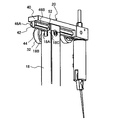
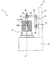
- FIG. 1 is a perspective view showing the entire configuration of a roundness measuring apparatus according to the present invention.
- the roundness measuring apparatus 1 shown in the figure includes a base 10 that supports the entire apparatus at the lower end, and a rotation axis ( ⁇ -axis) along the vertical direction (Z-axis direction) is formed on the upper surface of the base 10. )
- a stage 12 that is rotatable in the circumferential direction is provided.
- a columnar or cylindrical workpiece W that is a measurement object is placed on the upper surface of the stage 12. Further, the workpiece W is placed so that the central axis thereof is coaxial with the rotation axis of the mounting table 12.
- work W in the figure illustrates the workpiece
- a rotation drive unit (not shown) that includes a motor connected to the mounting table 12 and that rotationally drives the mounting table 12 is provided.
- the workpiece W placed on the stage 12 is rotated in the direction around the ⁇ axis together with the stage 12 by the rotation driving unit.
- stage 12 may be manually rotated. Further, the mounting table 12 may be movable in the direction perpendicular to the ⁇ axis and in the left-right direction and the front-rear direction orthogonal to each other by rotating the knob.
- a detector 24 (measurement probe) is supported on the upper surface side of the base 10 via a detector support mechanism 13 having a column 14, a carriage 16, a turning arm 18, a radial movement arm 20, and a detector holder 22.
- the detector 24 is provided, for example, in a measuring element 24B (stylus) extending in a rod shape from the lower end of the cylindrical detector main body 24A, and inside the detector main body 24A, and detects a displacement amount of the measuring element 24B by an operating transformer or the like. And a displacement detector (not shown) for outputting as an electrical signal.
- the measuring element 24B is supported by the detector main body 24A so that the axis line of the measuring element 24B can be displaced in a direction (displacement direction) perpendicular to the axis line in one plane, and one direction (attachment) of the displacement direction is attached. Is biased by a spring or the like.
- the detector support mechanism 13 will be described.
- a column 14 extending in the vertical direction is provided on the right side of the mounting table 12.
- the column 14 supports a carriage 16 that can move in the vertical direction along the column 14.
- the carriage 16 moves up and down by, for example, driving of a motor, but may be moved manually by rotating a knob or the like.
- the detector support mechanism 13 supports the detector 24 so that the position in the vertical direction can be changed by the moving mechanism of the carriage 16 in the vertical direction.
- One end (base end) of the swivel arm 18 is coupled to the carriage 16 so as to be pivotable around a swivel axis extending in the left-right direction on the left side of the column 14 (on the table 12 side).
- the swivel arm 18 is formed in a quadrangular prism shape, and by rotating the knob 30 to loosen the screw, the swivel arm 18 can be swung around the swivel axis to change the direction of the swivel arm 18.
- the left-right direction is a radial direction (R-axis direction) centered on the rotation axis ( ⁇ -axis) of the mounting table 12, that is, a direction (from the position of the turning axis in the carriage 16 toward the rotation axis of the mounting table 12 ( And the opposite direction) and the radial direction.
- the detector support mechanism 13 supports the detector 24 so that the turning angle around the turning axis along the radial direction can be changed by the turning mechanism of the turning arm 18.
- a radial movement arm 20 extending in the radial direction is supported at the distal end of the turning arm 18 so as to be movable in the radial direction.
- the radial movement arm 20 moves in a direction corresponding to the rotation direction by rotating the knob 32.
- the detector support mechanism 13 supports the position of the detector 24 in the radial direction so as to be changeable by the radial movement mechanism of the radial movement arm 20.
- a detector holder 22 is fixed to the tip of the radial movement arm 20, and the detector 24 is detachably attached to the detector holder 22 by rotating a knob 34.
- the detector holder 22 is such that the distal end side of the detector 24 (side on which the measuring element 24B is provided) is directed to the axis of the turning axis of the turning arm 18, and the axis of the detector main body 24A is the turning arm.
- the base end side of the detector 24 is fixed so as to be parallel to the 18 axis.
- the detector holder 22 can be fixed by changing the mounting angle of the detector 24, that is, the rotation angle around the axis of the detector main body 24A.
- the displacement direction and the urging direction of the probe 24B can be adjusted by a mechanism for adjusting the mounting angle of the detector 24 in the detector holder 22.
- FIG. 2 is a perspective view showing the upper ends of the radial movement arm 20 and the turning arm 18, and FIG. 3 is a cross-sectional view showing a cross section including the axis of the turning arm 18 and perpendicular to the radial direction. It is.
- the radial movement arm 20 has a quadrangular columnar arm body 40 extending along the radial direction.
- a quadrangular columnar rack member 42 extending along the radial direction is fixed to the side surface of the arm body 40 along the radial direction and on the side surface of the pivot arm 18 on the pivot axis side.
- a rack gear 44 that meshes with a pinion gear 60 described later is formed on the side surface of the rack member 42 in the radial direction and on the side surface of the swing arm 18 on the swing axis side.
- a rectangular columnar rail member 46A extending along the radial direction is provided on each of two side surfaces that are opposite to each other along the radial direction of the rack member 42 and that face the direction around the pivot axis of the pivot arm 18. 46B is fixed.
- the rail members 46A and 46B are engaged with the tip of the revolving arm 18 and supported so as to be movable in the radial direction.
- the distal end portion of the swivel arm 18 has projecting portions 18B and 18C that project in a bifurcated manner by a groove 18A formed along the radial direction, and rectilinear guides 50 and 52 are embedded in the projecting portions 18B and 18C. .
- Each of the linear guides 50 and 52 is formed with guide grooves 50A and 52A along the radial direction.
- the rack member 42 of the radial movement arm 20 is fitted into the groove 18A between the projecting portions 18B and 18C so as to be movable in the radial direction, and the rack member is inserted into each of the guide grooves 50A and 52A of the linear guides 50 and 52.
- Each of the 42 rail members 46A and 46B is fitted so as to be movable in the radial direction.
- the radial movement arm 20 is supported by the tip of the revolving arm 18 so as to be movable in the radial direction.
- a rotating member 54 extending along a direction perpendicular to the axial direction and the radial direction of the swing arm 18 is disposed in the groove 18A at the tip of the swing arm 18.
- Each of the protrusions 18B and 18C is formed with holes 56A and 56B into which the rotation member 54 is inserted, and bearings 58A and 58B are provided in the holes 56A and 56B, and the rotation member 54 is formed by the bearings 58A and 58B. It is supported rotatably.
- the rotation member 54 is formed with a pinion gear 60 at a portion facing the rack gear 44 formed on the rack member 42 of the radial movement arm 20, and the pinion gear 60 meshes with the rack gear 44.
- one end portion of the rotating member 54 is inserted through the hole 56A of the protruding portion 18B and protruded from the hole 56A, and the knob 32 is fixed to the protruding portion.
- the pinion gear 60 is rotated through the rotating member 54.
- the radial movement arm 20 moves in the radial direction via the engagement between the pinion gear 60 and the rack gear 44.
- the configuration of the radial movement mechanism of the radial movement arm 20 in the present embodiment is an example and may be an arbitrary configuration, and the radial movement arm 20 is moved in the radial direction by driving a motor. It may be. Similarly, the turning arm 18 may be turned by driving a motor.
- the carriage 16 is moved up and down by the movement mechanism of the carriage 16 in the up and down direction.
- the position of the tip of the probe 24B in the detector 24 in the vertical direction can be adjusted.
- the radial position of the radial movement arm 20 is adjusted and the diameter of the tip of the measuring element 24B is adjusted.
- the position in the direction (R-axis direction) can be adjusted.
- the turning angle of the turning arm 18 can be adjusted to adjust the angle of the axis of the measuring element 24B in the direction around the turning axis. it can.
- the tip of the probe 24B can be moved.
- the pivot axis is fixed with respect to the carriage 16 in this embodiment.
- the roundness measuring device 1 detects the roundness of each surface of the workpiece W having the cylindrical portion wa and the flange portion wb shown in FIG. A method of bringing the tip of the probe 24B of the instrument 24 into contact with each surface will be described.
- the work W is placed on the stage 12 so that the center axis of the work W is coaxial with the rotation axis ( ⁇ axis) of the stage 12.
- the vertical position of the carriage 16 in the detector support mechanism 13, the radial position of the radial movement arm 20, the turning angle of the turning arm 18, and the mounting angle of the detector 24 in the detector holder 22 are measured.
- the tip of the probe 24B is set so as to contact the measurement target surface, the displacement direction of the measurement probe 24B is perpendicular to the measurement target surface, and the biasing direction of the measurement probe 24B is directed to the measurement target surface. Is set as follows.
- the detector 24 has a detector holder 22 at an attachment angle so that the displacement direction of the probe 24B is the radial direction and the urging direction of the probe 24B is opposite to the direction toward the turning arm 18. To be held in.
- the vertical position of the carriage 16 and the radial position of the radial movement arm 20 are set to positions where the tip of the measuring element 24B comes into contact with the upper outer peripheral surface of the workpiece W that is the measurement target surface.
- the roundness of the upper outer peripheral surface of the workpiece W is measured by acquiring the displacement amount of the measuring element 24B detected by the detector 24 while rotating the workpiece W by the rotation of the mounting table 12. It can be carried out.
- the tip of the probe 24B can also be brought into contact with the upper outer peripheral surface by setting the turning angle (90 degrees) to be rearward and supporting the detector 24 so that the axial direction of the detector main body 24A is the front-rear direction. it can.
- the detector 24 has a detector holder 22 at an attachment angle so that the displacement direction of the probe 24B is the radial direction and the urging direction of the probe 24B is opposite to the direction toward the swivel arm 18.
- the position in the vertical direction of the carriage 16 and the position in the radial direction of the radial movement arm 20 are set to positions where the tip of the measuring element 24B comes into contact with the upper outer peripheral surface of the workpiece W that is the measurement target surface. .
- the swing arm 18 is set at a swing angle (0 degree) that is upward in the vertical direction (Z-axis direction) as shown in FIGS. Is set.
- the detector 24 is fixed to the detector holder 22 so that the displacement direction of the probe 24B is the radial direction and the mounting angle is such that the urging direction of the probe 24B is directed to the turning arm 18. .
- the vertical position of the carriage 16 and the radial position of the radial movement arm 20 are set to positions where the tip of the measuring element 24B comes into contact with the inner peripheral surface of the workpiece W, which is the measurement target surface.
- the roundness of the inner peripheral surface of the workpiece W can be measured by acquiring the displacement of the probe 24B detected by the detector 24 while rotating the workpiece W by the rotation of the mounting table 12. It can be carried out.
- the outer peripheral surface (lower outer peripheral surface) which is the outer peripheral surface of the cylindrical portion wa of the workpiece W and is lower than the flange portion wb is the measurement target surface, as shown in FIGS. It is set to a turning angle (90 degrees) that is the backward direction in the front-rear direction.
- the detector 24 has a detector holder 22 at an attachment angle so that the displacement direction of the probe 24B is the radial direction and the urging direction of the probe 24B is opposite to the direction toward the turning arm 18. To be held in.
- the vertical position of the carriage 16 and the radial position of the radial movement arm 20 are set to positions where the tip of the measuring element 24B comes into contact with the lower outer peripheral surface of the workpiece W, which is the measurement target surface.
- the roundness of the lower outer peripheral surface of the workpiece W is measured by acquiring the displacement of the probe 24B detected by the detector 24 while rotating the workpiece W by the rotation of the mounting table 12. It can be performed.
- the tip of the probe 24B of the detector 24 can be brought into contact with an arbitrary cylindrical surface of the cylindrical or columnar workpiece W.
- the tip of the measuring element 24B can be brought into contact by adjusting the turning angle of the turning arm 18 even on a cylindrical surface (the lower outer peripheral face) where the measuring piece 24B cannot be contacted from above.
- the roundness measuring apparatus 1 can perform other measurements related to the shape accuracy of the workpiece surface as well as the roundness. For example, the flatness of each of the upper surface and the lower surface of the flange portion wb of the workpiece W in FIG. Etc. can also be measured.
- the swivel arm 18 is set to a swivel angle (90 degrees) that is backward in the front-rear direction. .
- the detector 24 is fixed to the detector holder 22 at an attachment angle so that the displacement direction of the probe 24B is in the vertical direction and the urging direction of the probe 24B is downward.
- the vertical position of the carriage 16 and the radial position of the radial movement arm 20 are set to positions where the tip of the measuring element 24B comes into contact with the upper surface of the flange portion wb that is the measurement target surface.
- the flatness of the upper surface of the flange portion wb can be measured by acquiring the displacement of the probe 24B detected by the detector 24 while rotating the workpiece W by the rotation of the mounting table 12. .
- the swing arm 18 is set to a swing angle (90 degrees) that is backward in the front-rear direction. .
- the detector 24 is fixed to the detector holder 22 so that the displacement direction of the probe 24B is in the vertical direction and the urging direction of the probe 24B is upward.
- the vertical position of the carriage 16 and the radial position of the radial movement arm 20 are set so that the tip of the measuring element 24B comes into contact with the lower surface of the flange portion wb that is the measurement target surface.
- the flatness of the lower surface of the flange portion wb can be measured by acquiring the displacement amount of the probe 24B detected by the detector 24 while rotating the workpiece W by the rotation of the mounting table 12. .
- FIG. 12 and 13 are front views showing the detector support mechanism 102 in the known roundness measuring apparatus 100.
- FIG. 1 the same or similar components as those of the roundness measuring apparatus 1 of the present embodiment are denoted by the same reference numerals, description thereof is omitted, and different constituent elements are provided. Only will be described.
- the radial movement arm 104 extending along the radial direction is supported by the carriage 16 so as to be movable in the radial direction.
- the turning arm 18 is connected to the tip of the radial movement arm 104 so as to be turnable around a turning axis along the radial direction.
- the base end portion of the radial fixed arm 106 extending along the radial direction is fixed to the distal end portion of the turning arm 18 instead of the radial movement arm 20 of the present embodiment.
- the detector holder 22 is fixed to the distal end portion of the radial fixing arm 106.
- the turning arm 18 is set to a turning angle (0 degree) that is upward in the vertical direction (Z-axis direction).
- the measuring element 24B is used as shown in FIG. 13 is set to be opposite to the direction toward the swivel arm 18, and when the inner peripheral surface is the measurement target surface, the biasing direction of the probe 24B is the swivel arm as shown in FIG. The direction is set to be opposite to the direction toward 18.
- the vertical position of the carriage 16 and the radial position of the radial movement arm 104 are set to positions where the tip of the measuring element 24B comes into contact with the outer peripheral surface or inner peripheral surface of the workpiece W that is the measurement target surface.
- the workpiece W shown in FIGS. 12 and 13 is a workpiece having the maximum outer diameter and the minimum inner diameter that can be measured by the roundness measuring apparatus 100, and the tip of the measuring element 24B contacts the outer peripheral surface of the workpiece W.
- it is set at a position farthest from the rotation axis ( ⁇ axis) of the mounting table 12 in a range in which the radial movement arm 104 can move in the radial direction.
- FIGS. 14 and 15 show the maximum outer diameter and the minimum inner diameter that can measure the workpiece W having the same outer diameter and inner diameter as those in FIGS. 12 and 13 in the roundness measuring apparatus 1 of the present embodiment.
- the detector support mechanism 13 when designed as a workpiece is shown. That is, when the tip of the measuring element 24B is brought into contact with the outer peripheral surface of the workpiece W, as shown in FIG. 14, the rotation axis ( ⁇ of the mounting table 12 within the range in which the radial movement arm 20 is movable in the radial direction is used. It is set at the position farthest from the axis.
- the roundness measuring apparatus 1 of the present embodiment can be reduced in size.
- the detector support mechanism 102 of the roundness measuring apparatus 100 in FIG. 12 it is necessary to provide a space in which the radial fixing arm 106 is interposed between the detector 24 (the outer peripheral surface of the workpiece W) and the column 14.
- the detector support mechanism 13 of the roundness measuring device 1 of the present embodiment in FIG. 14 the detector 24 is moved to the vicinity of the column 14 by narrowing the distance between the detector 24 and the swivel arm 18. Can be made. Therefore, in the roundness measuring device 1 of the present embodiment in FIG. 14, it is not necessary to provide a space for interposing the radial fixing arm 106, and the size of the base 10 in the left-right direction is reduced.
- the roundness measuring apparatus 1 of the present embodiment in FIG. The smallest possible inner diameter can be measured. Therefore, the roundness measuring apparatus 1 of the present embodiment is not limited to the size of the inner diameter that can be measured with respect to the roundness measuring apparatus 100 in FIGS.
- the radial arm is used as the configuration of the detector holder support mechanism that supports the detector holder 22 via the radially extending arm (radial arm) supported by the tip of the swivel arm 18.
- the detector 24 detector holder 22
- the measurement space and the base 10 can be reduced in size,
- the size measuring device 1 is miniaturized.
- the base end of the radial fixing arm 120 extending along the radial direction is fixed to the distal end of the swivel arm 18.
- the detector holder 22 may be configured to be movable in the radial direction with respect to the radial direction fixed arm 120.
- the mechanism for moving the detector holder 22 in the radial direction may be any configuration, and may be manually moved or moved by driving a motor.
- W ... Workpiece 1,100 ... Roundness measuring device, 10 ... Base, 12 ... Mount table, 13, 102 ... Detector support mechanism, 14 ... Column, 16 ... Carriage, 18 ... Swivel arm, 20, 104 ... Radial moving arm, 22 ... Detector holder, 24 ... Detector, 24A ... Detector body, 24B ... Measuring element, 106 ... Radial direction fixed arm
Abstract
A roundness measurement device 1 according to the present invention has a base 10, a stage 12 that is provided on the base 10 and on which a workpiece W is placed, a column 14 made to stand on the base 10, a carriage 16 supported so as to be capable of moving along the column 14, a turning arm 18 supported by the carriage 16 so as to be capable of turning around a turning axis in the radial direction (left-right direction), a radial direction movement arm 20 supported so as to be capable of moving in the radial direction, and a detector holder 22 fixed to the leading end of the radial direction movement arm 20. A detector 24 is fixed to the detector holder 22, and the position of the detector in the radial direction is adjusted through the movement of the radial direction movement arm 20 in the radial direction.
Description
本発明は真円度測定装置に係り、特にテーブル上に回転可能に設置されたワークの表面に測定子先端を接触させ、回転角度に応じた測定子先端の変位を検出器により検出する真円度測定装置に関する。
The present invention relates to a roundness measuring apparatus, and in particular, a perfect circle in which a probe tip is brought into contact with the surface of a workpiece rotatably installed on a table, and a displacement of the probe tip according to a rotation angle is detected by a detector. It relates to a degree measuring device.
従来の真円度測定装置は、特許文献1のように回転テーブルに載置された円筒面を有するワークに対して径方向に移動する径方向移動アームを有し、径方向移動アームの先端に検出器ホルダを介して検出器(測定プローブ)が取り付けられる。
A conventional roundness measuring device has a radial movement arm that moves in a radial direction with respect to a workpiece having a cylindrical surface placed on a rotary table as in Patent Document 1, and is provided at the tip of the radial movement arm. A detector (measurement probe) is attached via a detector holder.
ワークの円筒面の真円度、同心度、又は同軸度などの真円度に関する測定を行う際には、径方向移動アームを移動させて検出器の測定子を円筒面に接触させ、ワークを回転テーブルにより回転させながら測定子の変位を検出する。
When measuring the roundness, concentricity, or concentricity of the cylindrical surface of the workpiece, move the radial movement arm to bring the detector probe into contact with the cylindrical surface and move the workpiece. The displacement of the probe is detected while being rotated by the rotary table.
ところで、特許文献1のような真円度測定装置では、径方向移動アームの先端よりも更に先端側に検出器ホルダを介して検出器が配置されている。そのため、検出器と径方向移動アームとの間にスペースがあり、その分、装置が大型化するという欠点がある。
By the way, in the roundness measuring apparatus as in Patent Document 1, the detector is arranged via the detector holder further on the tip side than the tip of the radial movement arm. For this reason, there is a space between the detector and the radial movement arm, and there is a disadvantage that the apparatus is enlarged accordingly.
本発明は、このような事情に鑑みてなされたもので、小型化を図ることができる真円度測定装置を提供することを目的とする。
The present invention has been made in view of such circumstances, and an object of the present invention is to provide a roundness measuring device that can be miniaturized.
上記目的を達成するため、本発明の一の態様に係る真円度測定装置は、ベースと、ベース上に設けられ、測定対象物を載置する載物台であって、上下方向に沿った回転軸の周りに回転可能な載物台と、ベース上に立設され、上下方向に延びるコラムと、コラムに沿って上下方向に移動可能にコラムに支持されたキャリッジと、載物台の回転軸に向う径方向に沿った旋回軸の周りに旋回可能にキャリッジに支持された旋回アームであって、径方向に垂直な方向に沿って延びる旋回アームと、検出器を固持する検出器ホルダと、旋回アームの先端部に支持された径方向アームであって径方向に延びる径方向アームを介して検出器ホルダを径方向に移動可能に支持する検出器ホルダ支持機構と、を備える。
In order to achieve the above object, a roundness measuring apparatus according to an aspect of the present invention is a base and a mounting table that is provided on the base and mounts an object to be measured, along the vertical direction. A stage that can rotate around a rotation axis, a column that stands on the base and extends in the vertical direction, a carriage that is supported by the column so as to be movable in the vertical direction along the column, and a rotation of the stage A swivel arm supported by a carriage so as to be able to swivel about a swivel axis along a radial direction toward the axis, the swivel arm extending along a direction perpendicular to the radial direction, and a detector holder for holding the detector A detector holder support mechanism which is a radial arm supported by the distal end portion of the turning arm and supports the detector holder so as to be movable in the radial direction via the radial arm extending in the radial direction.
本態様によれば、円筒状又は円柱状の測定対象物の外径が大きい程、検出器ホルダ(検出器)と旋回アームとの間隔を狭くして測定対象物の外周面の測定を行うことができるため、コラムと載物台との間隔を狭くすることができ、装置の小型化が図れる。
According to this aspect, the larger the outer diameter of the cylindrical or columnar measurement object, the narrower the distance between the detector holder (detector) and the swivel arm, and the measurement of the outer peripheral surface of the measurement object. Therefore, the interval between the column and the mounting table can be narrowed, and the apparatus can be miniaturized.
また、旋回アームをコラムに対して載物台側に配置することで、検出器を径方向に移動させる径方向アームをキャリッジに設ける場合と比べて、コラムに対して載物台の反対側に突出する径方向アームの突出量を少なくすることができる。したがって、測定に要する測定スペースを小さくすることができ、測定スペースも含めた装置の大きさを小さくすることができる。
Also, by placing the swivel arm on the stage side with respect to the column, compared to the case where a radial arm for moving the detector in the radial direction is provided on the carriage, it is on the opposite side of the stage with respect to the column. The protruding amount of the protruding radial arm can be reduced. Therefore, the measurement space required for the measurement can be reduced, and the size of the apparatus including the measurement space can be reduced.
本発明の他の態様に係る真円度測定装置において、検出器ホルダ支持機構は、径方向アームの先端部に検出器ホルダが固定され、径方向アームが径方向に移動可能に旋回アームの先端部に支持された態様とすることができる。
In the roundness measuring apparatus according to another aspect of the present invention, the detector holder support mechanism has a detector holder fixed to the distal end portion of the radial arm, and the distal end of the swivel arm is movable in the radial direction. It can be set as the aspect supported by the part.
本発明の更に他の態様に係る真円度測定装置において、径方向アームは、径方向に沿って形成されたラックギアを備え、旋回アームは、手動により回転するピニオンギアであって、ラックギアに係合するピニオンギアを備えた態様とすることができる。
In the roundness measuring apparatus according to still another aspect of the present invention, the radial arm includes a rack gear formed along the radial direction, and the swivel arm is a pinion gear that is manually rotated and is associated with the rack gear. It can be set as the aspect provided with the pinion gear to match.
本発明の更に他の態様に係る真円度測定装置において、検出器ホルダ支持機構は、径方向アームが旋回アームの先端部に固定され、径方向アームに沿って移動可能に検出器ホルダが支持された態様とすることができる。
In the roundness measuring device according to still another aspect of the present invention, the detector holder support mechanism is configured such that the radial arm is fixed to the distal end portion of the turning arm, and the detector holder is supported so as to be movable along the radial arm. It can be set as the mode which was made.
本発明によれば、真円度測定装置の小型化を図ることができる。
According to the present invention, the roundness measuring device can be downsized.
以下、添付図面に従って本発明の好ましい実施の形態について詳説する。
Hereinafter, preferred embodiments of the present invention will be described in detail with reference to the accompanying drawings.
図1は、本発明に係る真円度測定装置の全体構成を示した斜視図である。
FIG. 1 is a perspective view showing the entire configuration of a roundness measuring apparatus according to the present invention.
同図に示す真円度測定装置1は、下端部に装置全体を支持する台状のベース10を備え、ベース10の上面には、上下方向(Z軸方向)に沿った回転軸(θ軸)周り方向に回転可能な載物台12が設けられる。この載物台12の上面には、測定対象物となる円柱状又は円筒状のワークWが載置される。また、ワークWは、その中心軸が載物台12の回転軸と同軸上となるように載置される。なお、同図におけるワークWは、一定の外径と内径とを有する円筒部分waと、円筒部分waの外周面から径方向外側に円環状に突出するフランジ部分wbとを有するワークを例示している。
The roundness measuring apparatus 1 shown in the figure includes a base 10 that supports the entire apparatus at the lower end, and a rotation axis (θ-axis) along the vertical direction (Z-axis direction) is formed on the upper surface of the base 10. ) A stage 12 that is rotatable in the circumferential direction is provided. A columnar or cylindrical workpiece W that is a measurement object is placed on the upper surface of the stage 12. Further, the workpiece W is placed so that the central axis thereof is coaxial with the rotation axis of the mounting table 12. In addition, the workpiece | work W in the figure illustrates the workpiece | work which has the cylindrical part wa which has a fixed outer diameter and an internal diameter, and the flange part wb which protrudes in an annular | circular shape to the radial direction outer side from the outer peripheral surface of the cylindrical part wa. Yes.
ベース10の内部には、載物台12に連結されるモータ等を備え、載物台12を回転駆動する不図示の回転駆動部が設けられる。
Inside the base 10, a rotation drive unit (not shown) that includes a motor connected to the mounting table 12 and that rotationally drives the mounting table 12 is provided.
この回転駆動部により、載物台12に載置されたワークWは、載物台12と共にθ軸周り方向に回転する。
The workpiece W placed on the stage 12 is rotated in the direction around the θ axis together with the stage 12 by the rotation driving unit.
なお、載物台12は手動により回転するものであってもよい。また、載物台12は、θ軸に垂直な方向であって、互いに直交する左右方向及び前後方向に対してもつまみの回転操作等によって移動可能なものであってもよい。
It should be noted that the stage 12 may be manually rotated. Further, the mounting table 12 may be movable in the direction perpendicular to the θ axis and in the left-right direction and the front-rear direction orthogonal to each other by rotating the knob.
ベース10の上面側には、コラム14、キャリッジ16、旋回アーム18、径方向移動アーム20、検出器ホルダ22を有する検出器支持機構13を介して検出器24(測定プローブ)が支持される。
A detector 24 (measurement probe) is supported on the upper surface side of the base 10 via a detector support mechanism 13 having a column 14, a carriage 16, a turning arm 18, a radial movement arm 20, and a detector holder 22.
検出器24は、例えば円筒状の検出器本体24Aの下端から棒状に延びる測定子24B(スタイラス)と、検出器本体24Aの内部に設けられ、測定子24Bの変位量を作動トランス等により検出して電気信号として出力する不図示の変位検出部と、を有する。測定子24Bは、一平面内において測定子24Bの軸線がその軸線に直交する方向(変位方向)に変位可能に検出器本体24Aに支持されると共に、その変位方向のうちの一方の向き(付勢方向)にバネなどにより付勢される。
The detector 24 is provided, for example, in a measuring element 24B (stylus) extending in a rod shape from the lower end of the cylindrical detector main body 24A, and inside the detector main body 24A, and detects a displacement amount of the measuring element 24B by an operating transformer or the like. And a displacement detector (not shown) for outputting as an electrical signal. The measuring element 24B is supported by the detector main body 24A so that the axis line of the measuring element 24B can be displaced in a direction (displacement direction) perpendicular to the axis line in one plane, and one direction (attachment) of the displacement direction is attached. Is biased by a spring or the like.
検出器支持機構13について説明すると、ベース10の上面において載物台12の右側には、上下方向に沿って延在するコラム14が立設される。そして、コラム14には、コラム14に沿って上下方向に移動可能なキャリッジ16が支持される。キャリッジ16は、例えばモータの駆動により上下方向に移動するが、つまみの回転操作等によって手動で移動するものであってもよい。
The detector support mechanism 13 will be described. On the upper surface of the base 10, a column 14 extending in the vertical direction is provided on the right side of the mounting table 12. The column 14 supports a carriage 16 that can move in the vertical direction along the column 14. The carriage 16 moves up and down by, for example, driving of a motor, but may be moved manually by rotating a knob or the like.
このキャリッジ16の上下方向への移動機構により、検出器支持機構13は、検出器24を上下方向の位置を変更可能に支持する。
The detector support mechanism 13 supports the detector 24 so that the position in the vertical direction can be changed by the moving mechanism of the carriage 16 in the vertical direction.
キャリッジ16には、コラム14よりも左側(載物台12側)において旋回アーム18の一端(基端)が左右方向に沿った旋回軸の周りに旋回可能に連結される。旋回アーム18は、四角柱状に形成されており、つまみ30の回転操作によりネジを緩めることで、旋回アーム18を旋回軸周りに旋回させて、旋回アーム18の向きを変更することができる。なお、左右方向は、載物台12の回転軸(θ軸)を中心とする径方向(R軸方向)、即ち、キャリッジ16における旋回軸の位置から載物台12の回転軸に向う方向(及びその反対方向)に相当し、径方向というものとする。
One end (base end) of the swivel arm 18 is coupled to the carriage 16 so as to be pivotable around a swivel axis extending in the left-right direction on the left side of the column 14 (on the table 12 side). The swivel arm 18 is formed in a quadrangular prism shape, and by rotating the knob 30 to loosen the screw, the swivel arm 18 can be swung around the swivel axis to change the direction of the swivel arm 18. The left-right direction is a radial direction (R-axis direction) centered on the rotation axis (θ-axis) of the mounting table 12, that is, a direction (from the position of the turning axis in the carriage 16 toward the rotation axis of the mounting table 12 ( And the opposite direction) and the radial direction.
この旋回アーム18の旋回機構により、検出器支持機構13は、検出器24を径方向に沿った旋回軸周りの旋回角度を変更可能に支持する。
The detector support mechanism 13 supports the detector 24 so that the turning angle around the turning axis along the radial direction can be changed by the turning mechanism of the turning arm 18.
旋回アーム18の先端部には径方向に延びる径方向移動アーム20が径方向に移動可能に支持される。径方向移動アーム20は、つまみ32を回転操作することにより、その回転方向に応じた方向に移動する。
A radial movement arm 20 extending in the radial direction is supported at the distal end of the turning arm 18 so as to be movable in the radial direction. The radial movement arm 20 moves in a direction corresponding to the rotation direction by rotating the knob 32.
この径方向移動アーム20の径方向への移動機構により、検出器支持機構13は、検出器24の径方向の位置を変更可能に支持する。
The detector support mechanism 13 supports the position of the detector 24 in the radial direction so as to be changeable by the radial movement mechanism of the radial movement arm 20.
径方向移動アーム20の先端には検出器ホルダ22が固設され、検出器ホルダ22にはつまみ34の回転操作により着脱可能に検出器24が装着される。検出器ホルダ22は、検出器24の先端側(測定子24Bが設けられる側)が旋回アーム18の旋回軸の軸線上に向う方向となるように、かつ、検出器本体24Aの軸線が旋回アーム18の軸線と平行となるように検出器24の基端側を固持する。また、検出器ホルダ22は、検出器24の取付角度、即ち、検出器本体24Aの軸線周りの回転角度を変えて固持することができる。この検出器ホルダ22における検出器24の取付角度の調整機構により、測定子24Bの変位方向及び付勢方向を調整することができる。
A detector holder 22 is fixed to the tip of the radial movement arm 20, and the detector 24 is detachably attached to the detector holder 22 by rotating a knob 34. The detector holder 22 is such that the distal end side of the detector 24 (side on which the measuring element 24B is provided) is directed to the axis of the turning axis of the turning arm 18, and the axis of the detector main body 24A is the turning arm. The base end side of the detector 24 is fixed so as to be parallel to the 18 axis. The detector holder 22 can be fixed by changing the mounting angle of the detector 24, that is, the rotation angle around the axis of the detector main body 24A. The displacement direction and the urging direction of the probe 24B can be adjusted by a mechanism for adjusting the mounting angle of the detector 24 in the detector holder 22.
続いて、径方向移動アーム20の径方向への移動機構の構成について説明する。
Next, the configuration of the radial movement mechanism of the radial movement arm 20 will be described.
図2は、径方向移動アーム20及び旋回アーム18の上端部を示した斜視図であり、図3は、旋回アーム18の軸線を含む断面であって径方向に垂直な断面を示した断面図である。
2 is a perspective view showing the upper ends of the radial movement arm 20 and the turning arm 18, and FIG. 3 is a cross-sectional view showing a cross section including the axis of the turning arm 18 and perpendicular to the radial direction. It is.
これらの図に示すように径方向移動アーム20は、径方向に沿って延びる四角柱状のアーム本体40を有する。
As shown in these drawings, the radial movement arm 20 has a quadrangular columnar arm body 40 extending along the radial direction.
アーム本体40の径方向に沿った側面であって、旋回アーム18の旋回軸側の側面には、径方向に沿って延びる四角柱状のラック部材42が固設される。
A quadrangular columnar rack member 42 extending along the radial direction is fixed to the side surface of the arm body 40 along the radial direction and on the side surface of the pivot arm 18 on the pivot axis side.
ラック部材42の径方向に沿った側面であって、旋回アーム18の旋回軸側の側面には、後述のピニオンギア60と歯合するラックギア44が形成される。
A rack gear 44 that meshes with a pinion gear 60 described later is formed on the side surface of the rack member 42 in the radial direction and on the side surface of the swing arm 18 on the swing axis side.
ラック部材42の径方向に沿った互いに反対向きとなる2つの側面であって、旋回アーム18の旋回軸周り方向を向く側面の各々には、径方向に沿って延びる四角柱状のレール部材46A、46Bが固設される。
A rectangular columnar rail member 46A extending along the radial direction is provided on each of two side surfaces that are opposite to each other along the radial direction of the rack member 42 and that face the direction around the pivot axis of the pivot arm 18. 46B is fixed.
それらのレール部材46A、46Bは各々、旋回アーム18の先端部に係合されて径方向に移動可能に支持される。
The rail members 46A and 46B are engaged with the tip of the revolving arm 18 and supported so as to be movable in the radial direction.
旋回アーム18の先端部は、径方向に沿って形成された溝18Aにより二股状に突出する突出部18B、18Cを有し、それらの突出部18B、18Cに直進ガイド50、52が埋設される。直進ガイド50、52の各々には径方向に沿ったガイド溝50A、52Aが形成される。
The distal end portion of the swivel arm 18 has projecting portions 18B and 18C that project in a bifurcated manner by a groove 18A formed along the radial direction, and rectilinear guides 50 and 52 are embedded in the projecting portions 18B and 18C. . Each of the linear guides 50 and 52 is formed with guide grooves 50A and 52A along the radial direction.
そして、突出部18B、18Cの間の溝18Aに径方向移動アーム20のラック部材42が径方向に移動可能に嵌入されると共に、直進ガイド50、52のガイド溝50A、52Aの各々にラック部材42のレール部材46A、46Bの各々が径方向に移動可能に嵌入される。
The rack member 42 of the radial movement arm 20 is fitted into the groove 18A between the projecting portions 18B and 18C so as to be movable in the radial direction, and the rack member is inserted into each of the guide grooves 50A and 52A of the linear guides 50 and 52. Each of the 42 rail members 46A and 46B is fitted so as to be movable in the radial direction.
これによって、径方向移動アーム20が旋回アーム18の先端部に径方向に移動可能に支持される。
Thereby, the radial movement arm 20 is supported by the tip of the revolving arm 18 so as to be movable in the radial direction.
また、旋回アーム18の先端部の溝18Aには、旋回アーム18の軸線方向及び径方向に垂直な方向に沿って延びる回転部材54が配置される。突出部18B、18Cの各々には回転部材54が挿入される孔56A、56Bが形成されると共に、それらの孔56A、56Bにベアリング58A、58Bが設けられ、ベアリング58A、58Bにより回転部材54が回動自在に支持される。
Further, a rotating member 54 extending along a direction perpendicular to the axial direction and the radial direction of the swing arm 18 is disposed in the groove 18A at the tip of the swing arm 18. Each of the protrusions 18B and 18C is formed with holes 56A and 56B into which the rotation member 54 is inserted, and bearings 58A and 58B are provided in the holes 56A and 56B, and the rotation member 54 is formed by the bearings 58A and 58B. It is supported rotatably.
回転部材54には、径方向移動アーム20のラック部材42に形成されたラックギア44に対向する部分において、ピニオンギア60が形成されており、そのピニオンギア60がラックギア44に歯合される。
The rotation member 54 is formed with a pinion gear 60 at a portion facing the rack gear 44 formed on the rack member 42 of the radial movement arm 20, and the pinion gear 60 meshes with the rack gear 44.
また、回転部材54の一方の端部は、突出部18Bの孔56Aを挿通して孔56Aから突出され、その突出部分につまみ32が固定される。
Further, one end portion of the rotating member 54 is inserted through the hole 56A of the protruding portion 18B and protruded from the hole 56A, and the knob 32 is fixed to the protruding portion.
これにより、つまみ32を回転させることで、回転部材54を介してピニオンギア60が回転する。そして、ピニオンギア60が回転することで、ピニオンギア60とラックギア44との係合を介して、径方向移動アーム20が径方向に移動する。
Thus, by rotating the knob 32, the pinion gear 60 is rotated through the rotating member 54. When the pinion gear 60 rotates, the radial movement arm 20 moves in the radial direction via the engagement between the pinion gear 60 and the rack gear 44.
なお、本実施の形態における径方向移動アーム20の径方向への移動機構の構成は一例であって任意の構成としてよく、また、径方向移動アーム20はモータの駆動により径方向に移動するようにしてもよい。旋回アーム18についても同様にモータの駆動により旋回するようにしてもよい。
The configuration of the radial movement mechanism of the radial movement arm 20 in the present embodiment is an example and may be an arbitrary configuration, and the radial movement arm 20 is moved in the radial direction by driving a motor. It may be. Similarly, the turning arm 18 may be turned by driving a motor.
以上のように構成された真円度測定装置1の検出器支持機構13によれば、キャリッジ16の上下方向への移動機構によりキャリッジ16を上下方向に移動させることで、キャリッジ16の上下方向の位置を調整して検出器24における測定子24Bの先端の上下方向(Z軸方向)の位置を調整することができる。
According to the detector support mechanism 13 of the roundness measuring device 1 configured as described above, the carriage 16 is moved up and down by the movement mechanism of the carriage 16 in the up and down direction. By adjusting the position, the position of the tip of the probe 24B in the detector 24 in the vertical direction (Z-axis direction) can be adjusted.
また、径方向移動アーム20の径方向への移動機構により径方向移動アーム20を径方向に移動させることで、径方向移動アーム20の径方向の位置を調整して測定子24Bの先端の径方向(R軸方向)の位置を調整することができる。
Further, by moving the radial movement arm 20 in the radial direction by the radial movement mechanism of the radial movement arm 20, the radial position of the radial movement arm 20 is adjusted and the diameter of the tip of the measuring element 24B is adjusted. The position in the direction (R-axis direction) can be adjusted.
さらに、旋回アーム18の旋回機構により旋回アーム18を旋回軸周り方向に旋回させることで、旋回アーム18の旋回角度を調整して測定子24Bの軸線の旋回軸周り方向の角度を調整することができる。
Further, by turning the turning arm 18 in the direction around the turning axis by the turning mechanism of the turning arm 18, the turning angle of the turning arm 18 can be adjusted to adjust the angle of the axis of the measuring element 24B in the direction around the turning axis. it can.
なお、旋回アーム18の旋回軸を、キャリッジ16に対して、上下方向(Z軸方向)及び径方向(R軸方向)に垂直な前後方向に移動可能とすることで、測定子24Bの先端の前後方向の位置を調整可能にする形態も採用し得るが、本実施の形態では旋回軸はキャリッジ16に対して固定されているものとする。
In addition, by making the swivel axis of the swivel arm 18 movable in the front-rear direction perpendicular to the vertical direction (Z-axis direction) and the radial direction (R-axis direction) with respect to the carriage 16, the tip of the probe 24B can be moved. Although it is possible to adopt a form in which the position in the front-rear direction can be adjusted, it is assumed that the pivot axis is fixed with respect to the carriage 16 in this embodiment.
次に、上記真円度測定装置1において、図1に示した円筒部分waとフランジ部分wbとを有するワークWの各面の真円度等の測定を行う際に検出器支持機構13により検出器24の測定子24Bの先端を各面に接触させる方法について説明する。
Next, the roundness measuring device 1 detects the roundness of each surface of the workpiece W having the cylindrical portion wa and the flange portion wb shown in FIG. A method of bringing the tip of the probe 24B of the instrument 24 into contact with each surface will be described.
ワークWは、ワークWの中心軸が載物台12の回転軸(θ軸)と同軸上となるように載物台12上に載置される。
The work W is placed on the stage 12 so that the center axis of the work W is coaxial with the rotation axis (θ axis) of the stage 12.
そして、検出器支持機構13におけるキャリッジ16の上下方向の位置、径方向移動アーム20の径方向の位置、旋回アーム18の旋回角度、及び、検出器ホルダ22における検出器24の取付角度は、測定子24Bの先端が測定対象面に接触するように設定されると共に、測定子24Bの変位方向が測定対象面に垂直な方向で、測定子24Bの付勢方向が測定対象面に向かう方向となるように設定される。
Then, the vertical position of the carriage 16 in the detector support mechanism 13, the radial position of the radial movement arm 20, the turning angle of the turning arm 18, and the mounting angle of the detector 24 in the detector holder 22 are measured. The tip of the probe 24B is set so as to contact the measurement target surface, the displacement direction of the measurement probe 24B is perpendicular to the measurement target surface, and the biasing direction of the measurement probe 24B is directed to the measurement target surface. Is set as follows.
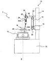
このとき、ワークWの円筒部分waにおける外周面であってフランジ部分wbよりも上側の外周面(上側外周面)を測定対象面とする場合、図4及び図5に示すように旋回アーム18は、上下方向(Z軸方向)の上向きとなる旋回角度(0度)に設定される。
At this time, when the outer peripheral surface (upper outer peripheral surface) which is the outer peripheral surface of the cylindrical portion wa of the workpiece W and is above the flange portion wb is the measurement target surface, as shown in FIGS. The turning angle (0 degree) is set to be upward in the vertical direction (Z-axis direction).
また、検出器24は、測定子24Bの変位方向が径方向となるように、かつ、測定子24Bの付勢方向が旋回アーム18への向きとは反対向きとなる取付角度で検出器ホルダ22に固持される。
In addition, the detector 24 has a detector holder 22 at an attachment angle so that the displacement direction of the probe 24B is the radial direction and the urging direction of the probe 24B is opposite to the direction toward the turning arm 18. To be held in.
そして、キャリッジ16の上下方向の位置と、径方向移動アーム20の径方向の位置は、測定子24Bの先端が測定対象面であるワークWの上側外周面に接触する位置に設定される。
The vertical position of the carriage 16 and the radial position of the radial movement arm 20 are set to positions where the tip of the measuring element 24B comes into contact with the upper outer peripheral surface of the workpiece W that is the measurement target surface.
これにより、載物台12の回転によりワークWを回転させながら検出器24により検出される測定子24Bの変位量を取得すること等により、ワークWの上側外周面の真円度等の測定を行うことができる。
Thus, the roundness of the upper outer peripheral surface of the workpiece W is measured by acquiring the displacement amount of the measuring element 24B detected by the detector 24 while rotating the workpiece W by the rotation of the mounting table 12. It can be carried out.
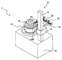
また、ワークWの上側外周面を測定対象面とする場合に測定子24Bの先端を上側外周面に接触させる他の方法として、図6及び図7に示すように旋回アーム18を、前後方向の後向きとなる旋回角度(90度)に設定し、検出器本体24Aの軸線方向が前後方向となるように検出器24を支持することによっても測定子24Bの先端を上側外周面に接触させることができる。
As another method of bringing the tip of the probe 24B into contact with the upper outer peripheral surface when the upper outer peripheral surface of the workpiece W is the measurement target surface, as shown in FIG. 6 and FIG. The tip of the probe 24B can also be brought into contact with the upper outer peripheral surface by setting the turning angle (90 degrees) to be rearward and supporting the detector 24 so that the axial direction of the detector main body 24A is the front-rear direction. it can.
なお、検出器24は、測定子24Bの変位方向が径方向となるように、かつ、測定子24Bの付勢方向が旋回アーム18への向きとは反対向きとなる取付角度で検出器ホルダ22に固持され、キャリッジ16の上下方向の位置と、径方向移動アーム20の径方向の位置は、測定子24Bの先端が測定対象面であるワークWの上側外周面に接触する位置に設定される。
The detector 24 has a detector holder 22 at an attachment angle so that the displacement direction of the probe 24B is the radial direction and the urging direction of the probe 24B is opposite to the direction toward the swivel arm 18. The position in the vertical direction of the carriage 16 and the position in the radial direction of the radial movement arm 20 are set to positions where the tip of the measuring element 24B comes into contact with the upper outer peripheral surface of the workpiece W that is the measurement target surface. .
ワークWの円筒部分waの内周面を測定対象面とする場合、図8及び図9に示すように旋回アーム18は、上下方向(Z軸方向)の上向きとなる旋回角度(0度)に設定される。
When the inner peripheral surface of the cylindrical portion wa of the workpiece W is a measurement target surface, the swing arm 18 is set at a swing angle (0 degree) that is upward in the vertical direction (Z-axis direction) as shown in FIGS. Is set.
また、検出器24は、測定子24Bの変位方向が径方向となるように、かつ、測定子24Bの付勢方向が旋回アーム18への向きとなる取付角度で検出器ホルダ22に固持される。
The detector 24 is fixed to the detector holder 22 so that the displacement direction of the probe 24B is the radial direction and the mounting angle is such that the urging direction of the probe 24B is directed to the turning arm 18. .
そして、キャリッジ16の上下方向の位置と、径方向移動アーム20の径方向の位置は、測定子24Bの先端が測定対象面であるワークWの内周面に接触する位置に設定される。
Then, the vertical position of the carriage 16 and the radial position of the radial movement arm 20 are set to positions where the tip of the measuring element 24B comes into contact with the inner peripheral surface of the workpiece W, which is the measurement target surface.
これにより、載物台12の回転によりワークWを回転させながら検出器24により検出される測定子24Bの変位量を取得すること等により、ワークWの内周面の真円度等の測定を行うことができる。
As a result, the roundness of the inner peripheral surface of the workpiece W can be measured by acquiring the displacement of the probe 24B detected by the detector 24 while rotating the workpiece W by the rotation of the mounting table 12. It can be carried out.
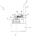
ワークWの円筒部分waにおける外周面であってフランジ部分wbよりも下側の外周面(下側外周面)を測定対象面とする場合、図10及び図11に示すように旋回アーム18は、前後方向の後向きとなる旋回角度(90度)に設定される。
When the outer peripheral surface (lower outer peripheral surface) which is the outer peripheral surface of the cylindrical portion wa of the workpiece W and is lower than the flange portion wb is the measurement target surface, as shown in FIGS. It is set to a turning angle (90 degrees) that is the backward direction in the front-rear direction.
また、検出器24は、測定子24Bの変位方向が径方向となるように、かつ、測定子24Bの付勢方向が旋回アーム18への向きとは反対向きとなる取付角度で検出器ホルダ22に固持される。
In addition, the detector 24 has a detector holder 22 at an attachment angle so that the displacement direction of the probe 24B is the radial direction and the urging direction of the probe 24B is opposite to the direction toward the turning arm 18. To be held in.
そして、キャリッジ16の上下方向の位置と、径方向移動アーム20の径方向の位置は、測定子24Bの先端が測定対象面であるワークWの下側外周面に接触する位置に設定される。
The vertical position of the carriage 16 and the radial position of the radial movement arm 20 are set to positions where the tip of the measuring element 24B comes into contact with the lower outer peripheral surface of the workpiece W, which is the measurement target surface.
これにより、載物台12の回転によりワークWを回転させながら検出器24により検出される測定子24Bの変位量を取得すること等により、ワークWの下側外周面の真円度等の測定を行うことができる。
As a result, the roundness of the lower outer peripheral surface of the workpiece W is measured by acquiring the displacement of the probe 24B detected by the detector 24 while rotating the workpiece W by the rotation of the mounting table 12. It can be performed.
以上のように、本実施の形態の検出器支持機構13によれば、円筒状又は円柱状のワークWの任意の円筒面に検出器24の測定子24Bの先端を接触させることができる。特に、上側からでは測定子24Bを接触させることができない円筒面(上記下側外周面)であっても旋回アーム18の旋回角度を調整することにより測定子24Bの先端を接触させることができる。
As described above, according to the detector support mechanism 13 of the present embodiment, the tip of the probe 24B of the detector 24 can be brought into contact with an arbitrary cylindrical surface of the cylindrical or columnar workpiece W. In particular, the tip of the measuring element 24B can be brought into contact by adjusting the turning angle of the turning arm 18 even on a cylindrical surface (the lower outer peripheral face) where the measuring piece 24B cannot be contacted from above.
なお、真円度測定装置1は、真円度に限らずワーク表面の形状精度に関する他の測定も行うことができ、例えば図1のワークWのフランジ部分wbの上面及び下面の各々の平面度等も測定することができる。
The roundness measuring apparatus 1 can perform other measurements related to the shape accuracy of the workpiece surface as well as the roundness. For example, the flatness of each of the upper surface and the lower surface of the flange portion wb of the workpiece W in FIG. Etc. can also be measured.
ワークWのフランジ部分wbの上面を測定対象面として平面度を測定する場合、図18及び図19に示すように旋回アーム18は、前後方向の後向きとなる旋回角度(90度)に設定される。
When the flatness is measured using the upper surface of the flange portion wb of the workpiece W as a measurement target surface, as shown in FIGS. 18 and 19, the swivel arm 18 is set to a swivel angle (90 degrees) that is backward in the front-rear direction. .
また、検出器24は、測定子24Bの変位方向が上下方向となるように、かつ、測定子24Bの付勢方向が下向きとなる取付角度で検出器ホルダ22に固持される。
Further, the detector 24 is fixed to the detector holder 22 at an attachment angle so that the displacement direction of the probe 24B is in the vertical direction and the urging direction of the probe 24B is downward.
そして、キャリッジ16の上下方向の位置と、径方向移動アーム20の径方向の位置は、測定子24Bの先端が測定対象面であるフランジ部分wbの上面に接触する位置に設定される。
Then, the vertical position of the carriage 16 and the radial position of the radial movement arm 20 are set to positions where the tip of the measuring element 24B comes into contact with the upper surface of the flange portion wb that is the measurement target surface.
これにより、載物台12の回転によりワークWを回転させながら検出器24により検出される測定子24Bの変位量を取得すること等により、フランジ部分wbの上面の平面度を測定することができる。
Thereby, the flatness of the upper surface of the flange portion wb can be measured by acquiring the displacement of the probe 24B detected by the detector 24 while rotating the workpiece W by the rotation of the mounting table 12. .
ワークWのフランジ部分wbの下面を測定対象面として平面度を測定する場合、図20及び図21に示すように旋回アーム18は、前後方向の後向きとなる旋回角度(90度)に設定される。
When the flatness is measured using the lower surface of the flange portion wb of the workpiece W as a measurement target surface, as shown in FIGS. 20 and 21, the swing arm 18 is set to a swing angle (90 degrees) that is backward in the front-rear direction. .
また、検出器24は、測定子24Bの変位方向が上下方向となるように、かつ、測定子24Bの付勢方向が上向きとなる取付角度で検出器ホルダ22に固持される。
Further, the detector 24 is fixed to the detector holder 22 so that the displacement direction of the probe 24B is in the vertical direction and the urging direction of the probe 24B is upward.
そして、キャリッジ16の上下方向の位置と、径方向移動アーム20の径方向の位置は、測定子24Bの先端が測定対象面であるフランジ部分wbの下面に接触する位置に設定される。
Then, the vertical position of the carriage 16 and the radial position of the radial movement arm 20 are set so that the tip of the measuring element 24B comes into contact with the lower surface of the flange portion wb that is the measurement target surface.
これにより、載物台12の回転によりワークWを回転させながら検出器24により検出される測定子24Bの変位量を取得すること等により、フランジ部分wbの下面の平面度を測定することができる。
Thereby, the flatness of the lower surface of the flange portion wb can be measured by acquiring the displacement amount of the probe 24B detected by the detector 24 while rotating the workpiece W by the rotation of the mounting table 12. .
続いて、本実施の形態の真円度測定装置1における検出器支持機構13の効果について説明する。
Subsequently, the effect of the detector support mechanism 13 in the roundness measuring device 1 of the present embodiment will be described.
図12及び図13は、周知の真円度測定装置100における検出器支持機構102を示した正面図である。なお、これらの図の真円度測定装置100において本実施の形態の真円度測定装置1と同一又は類似の作用の構成要素には同一符号を付して説明を省略し、相違する構成要素についてのみ説明する。
12 and 13 are front views showing the detector support mechanism 102 in the known roundness measuring apparatus 100. FIG. In the roundness measuring apparatus 100 of these drawings, the same or similar components as those of the roundness measuring apparatus 1 of the present embodiment are denoted by the same reference numerals, description thereof is omitted, and different constituent elements are provided. Only will be described.
これらの図の真円度測定装置100における検出器支持機構102では、径方向に沿って延びる径方向移動アーム104が径方向に移動可能にキャリッジ16に支持される。
In the detector support mechanism 102 in the roundness measuring apparatus 100 shown in these drawings, the radial movement arm 104 extending along the radial direction is supported by the carriage 16 so as to be movable in the radial direction.
旋回アーム18は、径方向移動アーム104の先端に径方向に沿った旋回軸の周りに旋回可能に連結される。
The turning arm 18 is connected to the tip of the radial movement arm 104 so as to be turnable around a turning axis along the radial direction.
また、旋回アーム18の先端部には、本実施の形態の径方向移動アーム20の代わりに、径方向に沿って延びる径方向固定アーム106の基端部が固定される。検出器ホルダ22は、径方向固定アーム106の先端部に固定される。
Further, the base end portion of the radial fixed arm 106 extending along the radial direction is fixed to the distal end portion of the turning arm 18 instead of the radial movement arm 20 of the present embodiment. The detector holder 22 is fixed to the distal end portion of the radial fixing arm 106.
このような検出器支持機構102において、図12及び図13のように断面図で示した円筒状のワークWの外周面又は内周面を測定対象面として真円度等の測定を行う場合、本実施の形態の検出器支持機構13と同様に、旋回アーム18は、上下方向(Z軸方向)の上向きとなる旋回角度(0度)に設定される。
In such a detector support mechanism 102, when measuring roundness or the like using the outer peripheral surface or inner peripheral surface of the cylindrical workpiece W shown in cross-sectional views as shown in FIGS. Similar to the detector support mechanism 13 of the present embodiment, the turning arm 18 is set to a turning angle (0 degree) that is upward in the vertical direction (Z-axis direction).
また、検出器24は、測定子24Bの変位方向が径方向となるように検出器ホルダ22に固持され、かつ、外周面を測定対象面とする場合には、図12のように測定子24Bの付勢方向が旋回アーム18への向きとは反対向きとなるように設定され、内周面を測定対象面とする場合には、図13のように測定子24Bの付勢方向が旋回アーム18への向きとは反対向きとなるように設定される。
In addition, when the detector 24 is fixed to the detector holder 22 so that the displacement direction of the measuring element 24B is the radial direction and the outer peripheral surface is the measurement target surface, the measuring element 24B is used as shown in FIG. 13 is set to be opposite to the direction toward the swivel arm 18, and when the inner peripheral surface is the measurement target surface, the biasing direction of the probe 24B is the swivel arm as shown in FIG. The direction is set to be opposite to the direction toward 18.
そして、キャリッジ16の上下方向の位置と、径方向移動アーム104の径方向の位置は、測定子24Bの先端が測定対象面であるワークWの外周面又は内周面に接触する位置に設定される。
The vertical position of the carriage 16 and the radial position of the radial movement arm 104 are set to positions where the tip of the measuring element 24B comes into contact with the outer peripheral surface or inner peripheral surface of the workpiece W that is the measurement target surface. The
ここで、図12及び図13に示すワークWは、真円度測定装置100により測定可能な最大外径と最小内径のワークを示しており、ワークWの外周面に測定子24Bの先端を接触させる際には、図12のように径方向移動アーム104が径方向に移動可能な範囲のうちの載物台12の回転軸(θ軸)から最も離れた位置に設定される。
Here, the workpiece W shown in FIGS. 12 and 13 is a workpiece having the maximum outer diameter and the minimum inner diameter that can be measured by the roundness measuring apparatus 100, and the tip of the measuring element 24B contacts the outer peripheral surface of the workpiece W. In this case, as shown in FIG. 12, it is set at a position farthest from the rotation axis (θ axis) of the mounting table 12 in a range in which the radial movement arm 104 can move in the radial direction.
ワークWの内周面に測定子24Bの先端を接触させる際には、図13のように径方向移動アーム104が径方向に移動可能な範囲のうちの載物台12の回転軸(θ軸)に最も近い位置に設定される。
When the tip of the probe 24B is brought into contact with the inner peripheral surface of the workpiece W, as shown in FIG. 13, the rotation axis (θ-axis) of the mounting table 12 within the range in which the radial movement arm 104 can move in the radial direction. ).
これに対して、図14及び図15は、本実施の形態の真円度測定装置1において、図12及び図13と同一の外径及び内径のワークWを測定可能な最大外径及び最小内径のワークとして設計した場合の検出器支持機構13を示す。即ち、ワークWの外周面に測定子24Bの先端を接触させる際には、図14のように径方向移動アーム20が径方向に移動可能な範囲のうちの載物台12の回転軸(θ軸)から最も離れた位置に設定される。
On the other hand, FIGS. 14 and 15 show the maximum outer diameter and the minimum inner diameter that can measure the workpiece W having the same outer diameter and inner diameter as those in FIGS. 12 and 13 in the roundness measuring apparatus 1 of the present embodiment. The detector support mechanism 13 when designed as a workpiece is shown. That is, when the tip of the measuring element 24B is brought into contact with the outer peripheral surface of the workpiece W, as shown in FIG. 14, the rotation axis (θ of the mounting table 12 within the range in which the radial movement arm 20 is movable in the radial direction is used. It is set at the position farthest from the axis.
ワークWの内周面に測定子24Bの先端を接触させる際には、図15のように径方向移動アーム20が径方向に移動可能な範囲のうちの載物台12の回転軸(θ軸)に最も近い位置に設定される。
When the tip of the probe 24B is brought into contact with the inner peripheral surface of the workpiece W, as shown in FIG. 15, the rotation axis (θ axis) of the mounting table 12 in the range in which the radial movement arm 20 can move in the radial direction. ).
ワークWの外周面を測定対象面として測定する場合の図12と図14とを比較すると、図12における真円度測定装置100の検出器支持機構102では、径方向移動アーム104がコラム14よりも右側に大きく突出するのに対して、図14における本実施の形態の真円度測定装置1の検出器支持機構13では、径方向移動アーム20がコラム14の右側にほとんど突出しない。
Comparing FIG. 12 and FIG. 14 when measuring the outer peripheral surface of the workpiece W as the measurement target surface, in the detector support mechanism 102 of the roundness measuring apparatus 100 in FIG. 14 protrudes greatly to the right side, whereas in the detector support mechanism 13 of the roundness measuring device 1 of the present embodiment in FIG. 14, the radial movement arm 20 hardly protrudes to the right side of the column 14.
したがって、図12の状態を上面側から示した図16の(A)部と図14の状態を上面側から示した図16の(B)部との比較からもわかるように、図12における周知の真円度測定装置100が測定に要するスペース(測定スペース100A)、即ち、真円度測定装置100の全ての構成要素を含む領域と比べて、本実施の形態の真円度測定装置1の測定スペース1Aは左右方向に縮小されている。したがって、本実施の形態の真円度測定装置1は小型化が図られる。
Therefore, as can be seen from a comparison between the part (A) of FIG. 16 showing the state of FIG. 12 from the upper surface side and the part (B) of FIG. 16 showing the state of FIG. Compared to the space (measurement space 100A) required for the roundness measuring apparatus 100 of the present invention, that is, the region including all the components of the roundness measuring apparatus 100, the roundness measuring apparatus 1 of the present embodiment The measurement space 1A is reduced in the left-right direction. Therefore, the roundness measuring apparatus 1 of the present embodiment can be reduced in size.
また、図12における真円度測定装置100の検出器支持機構102では、検出器24(ワークWの外周面)とコラム14との間に径方向固定アーム106を介在させる空間を設ける必要があるのに対して、図14における本実施の形態の真円度測定装置1の検出器支持機構13では、検出器24と旋回アーム18との間隔を狭めて検出器24をコラム14の近くまで移動させることができる。そのため、図14における本実施の形態の真円度測定装置1では、径方向固定アーム106を介在させる空間を設ける必要がなく、ベース10の左右方向の大きさも小型化される。
Further, in the detector support mechanism 102 of the roundness measuring apparatus 100 in FIG. 12, it is necessary to provide a space in which the radial fixing arm 106 is interposed between the detector 24 (the outer peripheral surface of the workpiece W) and the column 14. On the other hand, in the detector support mechanism 13 of the roundness measuring device 1 of the present embodiment in FIG. 14, the detector 24 is moved to the vicinity of the column 14 by narrowing the distance between the detector 24 and the swivel arm 18. Can be made. Therefore, in the roundness measuring device 1 of the present embodiment in FIG. 14, it is not necessary to provide a space for interposing the radial fixing arm 106, and the size of the base 10 in the left-right direction is reduced.
一方、図13と図15との比較からわかるように、このように小型化された図15における本実施の形態の真円度測定装置1においても、図13における真円度測定装置100により測定可能な最小内径の内周面を測定することができる。従って、本実施の形態の真円度測定装置1が、図12及び13における真円度測定装置100に対して測定可能な内径の大きさに制限が加わることも生じない。
On the other hand, as can be seen from a comparison between FIG. 13 and FIG. 15, the roundness measuring apparatus 1 of the present embodiment in FIG. The smallest possible inner diameter can be measured. Therefore, the roundness measuring apparatus 1 of the present embodiment is not limited to the size of the inner diameter that can be measured with respect to the roundness measuring apparatus 100 in FIGS.
以上、上記実施の形態では、旋回アーム18の先端部に支持された径方向に延びるアーム(径方向アーム)を介して検出器ホルダ22を支持する検出器ホルダ支持機構の構成として、径方向アームの一形態である径方向移動アーム20の径方向の移動により検出器24(検出器ホルダ22)を径方向に移動させる構成とすることで、測定スペース及びベース10の小型化を図り、真円度測定装置1の小型化を図るものである。これに対して、上記実施の形態の構成に限らず、検出器ホルダ22を旋回アーム18に対して径方向に移動可能にした構成であれば上記実施の形態と同様の効果が得られる。
As described above, in the above embodiment, the radial arm is used as the configuration of the detector holder support mechanism that supports the detector holder 22 via the radially extending arm (radial arm) supported by the tip of the swivel arm 18. By adopting a configuration in which the detector 24 (detector holder 22) is moved in the radial direction by the radial movement of the radial movement arm 20 which is one form, the measurement space and the base 10 can be reduced in size, The size measuring device 1 is miniaturized. On the other hand, not only the configuration of the above-described embodiment, but also a configuration in which the detector holder 22 can be moved in the radial direction with respect to the swivel arm 18 can provide the same effects as those of the above-described embodiment.
たとえば、径方向アームの一形態として径方向移動アーム20の代わりに、図17に示すように径方向に沿って延びる径方向固定アーム120の基端部を旋回アーム18の先端部に固定し、径方向固定アーム120に対して検出器ホルダ22を径方向に移動可能に設けた構成であってもよい。検出器ホルダ22を径方向に移動させる機構についてはどのような構成でもよく、手動により移動するものであってもよいし、モータの駆動により移動するものであってもよい。
For example, instead of the radial movement arm 20 as one form of the radial arm, as shown in FIG. 17, the base end of the radial fixing arm 120 extending along the radial direction is fixed to the distal end of the swivel arm 18. The detector holder 22 may be configured to be movable in the radial direction with respect to the radial direction fixed arm 120. The mechanism for moving the detector holder 22 in the radial direction may be any configuration, and may be manually moved or moved by driving a motor.
W…ワーク、1,100…真円度測定装置、10…ベース、12…載物台、13,102…検出器支持機構、14…コラム、16…キャリッジ、18…旋回アーム、20,104…径方向移動アーム、22…検出器ホルダ、24…検出器、24A…検出器本体、24B…測定子、106…径方向固定アーム
W ... Workpiece, 1,100 ... Roundness measuring device, 10 ... Base, 12 ... Mount table, 13, 102 ... Detector support mechanism, 14 ... Column, 16 ... Carriage, 18 ... Swivel arm, 20, 104 ... Radial moving arm, 22 ... Detector holder, 24 ... Detector, 24A ... Detector body, 24B ... Measuring element, 106 ... Radial direction fixed arm
Claims (4)
- ベースと、
前記ベース上に設けられ、測定対象物を載置する載物台であって、上下方向に沿った回転軸の周りに回転可能な載物台と、
前記ベース上に立設され、上下方向に延びるコラムと、
前記コラムに沿って上下方向に移動可能に前記コラムに支持されたキャリッジと、
前記載物台の前記回転軸に向う径方向に沿った旋回軸の周りに旋回可能に前記キャリッジに支持された旋回アームであって、前記径方向に垂直な方向に沿って延びる旋回アームと、
検出器を固持する検出器ホルダと、
前記旋回アームの先端部に支持された径方向アームであって前記径方向に延びる径方向アームを介して前記検出器ホルダを前記径方向に移動可能に支持する検出器ホルダ支持機構と、
を備えた真円度測定装置。 Base and
A stage that is provided on the base and on which a measurement object is to be placed, the stage being rotatable around a rotation axis along the vertical direction;
A column standing on the base and extending in the vertical direction;
A carriage supported by the column so as to be vertically movable along the column;
A swivel arm supported by the carriage so as to be able to swivel about a swivel axis along a radial direction toward the rotation axis of the object table, the swivel arm extending along a direction perpendicular to the radial direction;
A detector holder for holding the detector;
A detector holder support mechanism, which is a radial arm supported at the tip of the swivel arm and supports the detector holder movably in the radial direction via a radial arm extending in the radial direction;
Roundness measuring device with - 前記検出器ホルダ支持機構は、前記径方向アームの先端部に前記検出器ホルダが固定され、前記径方向アームが前記径方向に移動可能に前記旋回アームの先端部に支持された請求項1に記載の真円度測定装置。 2. The detector holder support mechanism according to claim 1, wherein the detector holder is fixed to a distal end portion of the radial arm, and the radial arm is supported by the distal end portion of the swivel arm so as to be movable in the radial direction. The roundness measuring device described.
- 前記径方向アームは、前記径方向に沿って形成されたラックギアを備え、前記旋回アームは、手動により回転するピニオンギアであって、前記ラックギアに係合するピニオンギアを備えた請求項1又は2に記載の真円度測定装置。 The said radial arm is equipped with the rack gear formed along the said radial direction, The said turning arm is a pinion gear rotated manually, Comprising: The pinion gear engaged with the said rack gear was provided. The roundness measuring device according to 1.
- 前記検出器ホルダ支持機構は、前記径方向アームが前記旋回アームの先端部に固定され、前記径方向アームに沿って移動可能に前記検出器ホルダが支持された請求項1に記載の真円度測定装置。 2. The roundness according to claim 1, wherein the detector holder support mechanism is configured such that the radial arm is fixed to a distal end portion of the turning arm, and the detector holder is supported so as to be movable along the radial arm. measuring device.
Priority Applications (1)
| Application Number | Priority Date | Filing Date | Title |
|---|---|---|---|
| EP16743094.1A EP3239654B1 (en) | 2015-01-28 | 2016-01-12 | Roundness measurement device |
Applications Claiming Priority (2)
| Application Number | Priority Date | Filing Date | Title |
|---|---|---|---|
| JP2015-014383 | 2015-01-28 | ||
| JP2015014383A JP5943099B1 (en) | 2015-01-28 | 2015-01-28 | Roundness measuring device |
Publications (1)
| Publication Number | Publication Date |
|---|---|
| WO2016121490A1 true WO2016121490A1 (en) | 2016-08-04 |
Family
ID=56244722
Family Applications (1)
| Application Number | Title | Priority Date | Filing Date |
|---|---|---|---|
| PCT/JP2016/050715 WO2016121490A1 (en) | 2015-01-28 | 2016-01-12 | Roundness measurement device |
Country Status (3)
| Country | Link |
|---|---|
| EP (1) | EP3239654B1 (en) |
| JP (1) | JP5943099B1 (en) |
| WO (1) | WO2016121490A1 (en) |
Cited By (3)
| Publication number | Priority date | Publication date | Assignee | Title |
|---|---|---|---|---|
| CN108413858A (en) * | 2018-06-07 | 2018-08-17 | 中国计量大学 | A kind of contact ball pen bead sizes form measuring instrument and measurement method |
| CN113624188A (en) * | 2021-08-27 | 2021-11-09 | 安庆振宜机动车零部件再制造有限公司 | Detection device for roundness of automobile parts |
| CN115847441A (en) * | 2022-12-19 | 2023-03-28 | 杭州电子科技大学 | Based on axle type work piece measuring robot |
Families Citing this family (2)
| Publication number | Priority date | Publication date | Assignee | Title |
|---|---|---|---|---|
| KR101834372B1 (en) | 2016-11-14 | 2018-03-05 | 한호산업(주) | Surface defect inspection apparatus for gear-parts |
| CN108955491B (en) * | 2018-07-30 | 2020-08-25 | 陕西柴油机重工有限公司 | Multifunctional chassis tool for measuring piston profile by roundness measuring instrument and measuring method thereof |
Citations (3)
| Publication number | Priority date | Publication date | Assignee | Title |
|---|---|---|---|---|
| JP2008070181A (en) * | 2006-09-13 | 2008-03-27 | Mitsutoyo Corp | Roundness measuring device calibration tool, and calibration method for the roundness measuring device |
| JP2011208994A (en) * | 2010-03-29 | 2011-10-20 | Mitsutoyo Corp | Roundness measuring machine |
| JP2013108757A (en) * | 2011-11-17 | 2013-06-06 | Tokyo Seimitsu Co Ltd | Circularity measuring instrument |
Family Cites Families (3)
| Publication number | Priority date | Publication date | Assignee | Title |
|---|---|---|---|---|
| US4679326A (en) * | 1984-11-21 | 1987-07-14 | Mitutoyo Mfg. Co., Ltd. | Height gauge |
| JP5336279B2 (en) * | 2009-07-08 | 2013-11-06 | 株式会社ミツトヨ | Surface texture measuring device and roundness measuring device |
| US8650939B2 (en) * | 2009-10-13 | 2014-02-18 | Mitutoyo Corporation | Surface texture measuring machine and a surface texture measuring method |
-
2015
- 2015-01-28 JP JP2015014383A patent/JP5943099B1/en active Active
-
2016
- 2016-01-12 WO PCT/JP2016/050715 patent/WO2016121490A1/en active Application Filing
- 2016-01-12 EP EP16743094.1A patent/EP3239654B1/en active Active
Patent Citations (3)
| Publication number | Priority date | Publication date | Assignee | Title |
|---|---|---|---|---|
| JP2008070181A (en) * | 2006-09-13 | 2008-03-27 | Mitsutoyo Corp | Roundness measuring device calibration tool, and calibration method for the roundness measuring device |
| JP2011208994A (en) * | 2010-03-29 | 2011-10-20 | Mitsutoyo Corp | Roundness measuring machine |
| JP2013108757A (en) * | 2011-11-17 | 2013-06-06 | Tokyo Seimitsu Co Ltd | Circularity measuring instrument |
Cited By (5)
| Publication number | Priority date | Publication date | Assignee | Title |
|---|---|---|---|---|
| CN108413858A (en) * | 2018-06-07 | 2018-08-17 | 中国计量大学 | A kind of contact ball pen bead sizes form measuring instrument and measurement method |
| CN113624188A (en) * | 2021-08-27 | 2021-11-09 | 安庆振宜机动车零部件再制造有限公司 | Detection device for roundness of automobile parts |
| CN113624188B (en) * | 2021-08-27 | 2024-03-15 | 安庆振宜机动车零部件再制造有限公司 | Detection device for roundness of automobile parts |
| CN115847441A (en) * | 2022-12-19 | 2023-03-28 | 杭州电子科技大学 | Based on axle type work piece measuring robot |
| CN115847441B (en) * | 2022-12-19 | 2023-07-28 | 杭州电子科技大学 | Shaft-based workpiece measuring robot |
Also Published As
| Publication number | Publication date |
|---|---|
| EP3239654A4 (en) | 2017-11-08 |
| EP3239654A1 (en) | 2017-11-01 |
| JP5943099B1 (en) | 2016-06-29 |
| EP3239654B1 (en) | 2018-11-14 |
| JP2016138831A (en) | 2016-08-04 |
Similar Documents
| Publication | Publication Date | Title |
|---|---|---|
| WO2016121490A1 (en) | Roundness measurement device | |
| US7197835B2 (en) | Detector supporting mechanism | |
| JP5880096B2 (en) | Inner diameter measuring device | |
| US9316476B2 (en) | Profile measuring instrument, adjusting method for profile measuring instrument, and profile measuring method | |
| JP2006231509A (en) | Method for measuring program control type machine tool | |
| JP5324510B2 (en) | Roundness measuring machine | |
| JP5971445B1 (en) | Roundness measuring device | |
| JP2006194739A (en) | Apparatus and method for measuring fluctuation of object to be measured | |
| JP5705092B2 (en) | Roundness measuring device | |
| EP2016366B1 (en) | Metrological apparatus for measuring surface characteristics | |
| US20230032119A1 (en) | Roundness measuring machine | |
| JP2017067512A (en) | Outer diameter measuring instrument and grinding device using the same | |
| JP5752313B2 (en) | Roundness measuring device | |
| JP2011232173A (en) | Dimension measuring apparatus and dimension measuring method | |
| JP2010271047A (en) | Apparatus for measuring shaft having optical type and touch probe type measuring mechanisms and shaft supporting mechanism, and method for measuring specifications and accuracy of shaft by the apparatus | |
| JP3654744B2 (en) | Roundness measuring machine | |
| JP6601939B2 (en) | Measuring device | |
| JP4437430B2 (en) | Conical surface shape measuring device | |
| JP6537950B2 (en) | Gauge inspection machine | |
| GB2493786A (en) | Merological apparatus | |
| JP5819019B2 (en) | Roundness measuring device and roundness measuring method | |
| JP2005172739A (en) | Apparatus and method for measuring amount of runout of tooth space | |
| JPH05141959A (en) | Screw effective diameter section deflection measuring device | |
| JP2005205571A (en) | Measuring device | |
| JP2003043179A (en) | Centering device and centering method of cylindrical subject |
Legal Events
| Date | Code | Title | Description |
|---|---|---|---|
| 121 | Ep: the epo has been informed by wipo that ep was designated in this application |
Ref document number: 16743094 Country of ref document: EP Kind code of ref document: A1 |
|
| REEP | Request for entry into the european phase |
Ref document number: 2016743094 Country of ref document: EP |
|
| NENP | Non-entry into the national phase |
Ref country code: DE |