JP2011208994A - Roundness measuring machine - Google Patents
Roundness measuring machine Download PDFInfo
- Publication number
- JP2011208994A JP2011208994A JP2010074846A JP2010074846A JP2011208994A JP 2011208994 A JP2011208994 A JP 2011208994A JP 2010074846 A JP2010074846 A JP 2010074846A JP 2010074846 A JP2010074846 A JP 2010074846A JP 2011208994 A JP2011208994 A JP 2011208994A
- Authority
- JP
- Japan
- Prior art keywords
- detector
- stylus
- drive mechanism
- mounting plate
- displacement amount
- Prior art date
- Legal status (The legal status is an assumption and is not a legal conclusion. Google has not performed a legal analysis and makes no representation as to the accuracy of the status listed.)
- Granted
Links
Images


Landscapes
- A Measuring Device Byusing Mechanical Method (AREA)
Abstract
【課題】作業能率の一層の向上が図れる真円度測定機を提供する。
【解決手段】真円度測定機において、被測定物Wの測定部位に対応して用意された複数種のスタイラス31を取出可能かつ格納可能に収容したスタイラスストッカ50と、制御装置60とを備える。制御装置は、測定指令が与えられた際、回転テーブル20の回転駆動機構23および検出器駆動機構40の動作を制御しながら、被測定物の真円度測定を実行する測定実行手段と、スタイラス自動交換指令が与えられた際、検出器駆動機構を制御しながら、検出器30とスタイラスストッカとの間でスタイラス交換動作を実行するスタイラス交換実行手段と、検出器自動ゲイン校正指令が与えられた際、スタイラスに予め設定された設定変位量を付与し、検出器によって検出されるスタイラスの変位と設定変位量とから検出器のゲインを校正するゲイン調整手段とを備える。
【選択図】図1A roundness measuring machine capable of further improving work efficiency is provided.
A roundness measuring machine includes a stylus stocker 50 that accommodates a plurality of types of styluses 31 that are prepared corresponding to the measurement site of a workpiece W and that can be stored therein, and a control device 60. . The control device, when given with a measurement command, controls the operation of the rotation drive mechanism 23 and the detector drive mechanism 40 of the turntable 20 while measuring the roundness of the object to be measured, and a stylus. When the automatic exchange command is given, the stylus exchange execution means for executing the stylus exchange operation between the detector 30 and the stylus stocker while controlling the detector driving mechanism, and the detector automatic gain calibration command are given. At this time, a gain adjustment means is provided that applies a preset set displacement amount to the stylus and calibrates the detector gain from the stylus displacement detected by the detector and the set displacement amount.
[Selection] Figure 1
Description
本発明は、真円度測定機に関する。詳しくは、スタイラスの自動交換機能および検出器の自動ゲイン校正機能を備えた真円度測定機に関する。 The present invention relates to a roundness measuring machine. More specifically, the present invention relates to a roundness measuring machine having an automatic stylus exchange function and an automatic gain calibration function of a detector.
被測定物の真円度を測定する測定機として、真円度測定機が知られている。
真円度測定機は、ベースと、このベース上に垂直軸線を中心に回転可能に設けられ上面に被測定物を載置する回転テーブルと、この回転テーブルを回転させる回転駆動機構と、ベース上に立設されたコラムと、このコラムに沿って上下方向へ昇降可能に設けられた昇降スライダと、この昇降スライダに垂直軸線に対して直交する方向へスライド可能に設けられたスライドアームと、このスライドアームの先端に取り付けられ被測定物に接するスタイラスの変位を電気信号として出力する検出器とを備える(例えば、特許文献1参照)。
A roundness measuring machine is known as a measuring machine that measures the roundness of an object to be measured.
The roundness measuring machine includes a base, a rotary table provided on the base so as to be rotatable about a vertical axis, and a measurement object placed on the upper surface, a rotary drive mechanism for rotating the rotary table, and a base A column that is erected on the column, a lift slider that is vertically movable along the column, a slide arm that is slidable in a direction perpendicular to the vertical axis on the lift slider, And a detector that outputs a displacement of a stylus that is attached to the tip of the slide arm and is in contact with the object to be measured as an electrical signal (see, for example, Patent Document 1).
真円度測定機を使用するにあたっては、予め、通常のスタイラスのほかに、被測定物の測定部位形状に合わせた各種形状のスタイラスが用意されているから、被測定物の測定部位形状に適したスタイラスに交換したのち、測定を行う。例えば、被測定物の深孔の真円度を測定する場合には、スタイラス長さが長い深孔用スタイラスに、あるいは、溝内の真円度を測定する場合には溝用スタイラスなどに交換したのち、測定を行う。
スタイラスの交換作業は、従来、測定者によって行われていため、測定作業の中断時間が長いうえ、スタイラスの取外作業および装着作業に伴う測定者への負担も大きい。
When using a roundness measuring machine, in addition to a normal stylus, various styluses that match the shape of the part being measured are prepared in advance, making it suitable for the shape of the part being measured. After replacing the stylus, measure. For example, when measuring the roundness of the deep hole of the object to be measured, replace it with a deep hole stylus with a long stylus length, or replace it with a groove stylus when measuring the roundness in the groove. Then, measure.
Since the stylus replacement work is conventionally performed by a measurer, the measurement work is interrupted for a long time, and the burden on the measurer associated with the stylus removal work and mounting work is large.
そこで、本出願人は、先に、スタイラスを自動交換できる真円度測定機を提案した(特許文献2参照)。
これは、上述した構成の真円度測定機に、被測定物の測定部位に対応して用意された複数種のスタイラスを取出可能かつ格納可能に収容したスタイラスストッカと、制御装置とが用意されている。制御装置は、測定指令が与えられた際、回転駆動機構、昇降スライダおよびスライドアームの動作を制御しながら、被測定物の真円度測定を実行するとともに、スタイラス交換指令が与えられた際、昇降スライダおよびスライドアームの動作を制御しながら、検出器とスタイラスストッカとの間でスタイラス交換動作を実行する。
Therefore, the present applicant has previously proposed a roundness measuring machine capable of automatically exchanging a stylus (see Patent Document 2).
The roundness measuring machine having the above-described configuration is provided with a stylus stocker that accommodates a plurality of types of styluses prepared corresponding to the measurement site of the object to be measured, and a control device. ing. The control device performs the roundness measurement of the object under measurement while controlling the operation of the rotation drive mechanism, the lifting slider and the slide arm when the measurement command is given, and when the stylus exchange command is given, A stylus exchange operation is executed between the detector and the stylus stocker while controlling the operations of the lift slider and the slide arm.
真円度測定機において、スタイラスの自動交換機能が付加されたことにより、スタイラスの自動交換が行えるから、作業能率の向上および測定者の負担軽減が図れるようになったものの、次のような課題が残る。
例えば、長さの異なるスタイラスに交換した場合、検出器のゲインを校正する必要がある。従来、検出器のゲイン校正作業は、ゲージブロックを組み合わせて所定の段差を作った校正用治具や、円盤状の外周縁の一部に平坦な切欠きを形成した校正用マスタなどを用いて、校正作業を行っている。
The roundness measuring machine has an automatic stylus replacement function, which enables automatic stylus replacement, improving work efficiency and reducing the burden on the measurer. Remains.
For example, when the stylus is replaced with a stylus having a different length, it is necessary to calibrate the gain of the detector. Conventionally, detector gain calibration work has been performed using a calibration jig with a predetermined step formed by combining gauge blocks, or a calibration master with a flat notch formed on a part of the outer periphery of the disk. Proofreading work.
具体的には、真円度測定機の回転テーブル上に、校正用治具や校正用マスタを測定者がセットし、この校正用治具や校正用マスタの段差や切欠きを検出器で測定し、この測定値と段差や切欠き量とから検出器のゲインを校正する。検出器のゲイン校正作業終了後、校正用治具や校正用マスタを回転テーブル上から取り外し、回転テーブル上に被測定物をセットしたのち、測定作業を行う。
そのため、スタイラスの自動交換機能により作業能率を向上させることができるようになっても、検出器のゲイン校正に時間や手間がかかるため、作業能率のより一層の向上が要望されている。
Specifically, the measurement person sets a calibration jig or calibration master on the rotary table of the roundness measuring machine, and measures the step or notch of the calibration jig or calibration master with a detector. Then, the gain of the detector is calibrated from the measured value and the level difference or notch amount. After the gain calibration of the detector is completed, the calibration jig and the calibration master are removed from the rotary table, the measurement object is set on the rotary table, and the measurement work is performed.
For this reason, even if the work efficiency can be improved by the automatic stylus exchange function, it takes time and labor to calibrate the gain of the detector, and thus further improvement of the work efficiency is desired.
本発明の目的は、このような要望に応え、作業能率をより一層向上させることができる真円度測定機を提供することにある。 An object of the present invention is to provide a roundness measuring machine capable of meeting such demands and further improving work efficiency.
本発明の真円度測定機は、ベースと、このベース上に垂直軸線を中心に回転可能に設けられ上面に被測定物を載置する回転テーブルと、この回転テーブルを回転させる回転駆動機構と、前記被測定物に接するスタイラスおよびこのスタイラスを着脱可能に装着するとともにこのスタイラスの変位を電気信号として出力する検出器本体を有する検出器と、この検出器を前記垂直軸線に対して直交しかつ前記回転テーブルに対して接近、離間する第1移動方向および前記垂直軸線と平行な第2移動方向へ駆動させる検出器駆動機構とを有する真円度測定機において、前記被測定物の測定部位に対応して用意された複数種のスタイラスを取出可能かつ格納可能に収容したスタイラスストッカと、制御装置とを備え、 前記制御装置は、測定指令が与えられた際、前記回転駆動機構および前記検出器駆動機構の動作を制御しながら、前記被測定物の真円度測定を実行する測定実行手段と、スタイラス自動交換指令が与えられた際、前記検出器駆動機構を制御しながら、前記検出器と前記スタイラスストッカとの間でスタイラス交換動作を実行するスタイラス交換実行手段と、検出器自動ゲイン校正指令が与えられた際、前記スタイラスに予め設定された設定変位量を付与し、前記検出器によって検出される前記スタイラスの変位と前記設定変位量とから前記検出器のゲインを校正するゲイン調整手段とを備える、ことを特徴とする。 A roundness measuring machine according to the present invention includes a base, a rotary table provided on the base so as to be rotatable about a vertical axis, and an object to be measured placed on the upper surface, and a rotation drive mechanism for rotating the rotary table, A detector having a stylus in contact with the object to be measured and a detector body that detachably mounts the stylus and outputs a displacement of the stylus as an electrical signal; and the detector orthogonal to the vertical axis and In a roundness measuring machine having a first movement direction approaching and separating from the rotary table and a detector driving mechanism for driving in a second movement direction parallel to the vertical axis, A stylus stocker that accommodates a plurality of types of styli prepared in a storable and retractable manner, and a control device, and the control device receives a measurement command. Measurement execution means for measuring the roundness of the object to be measured while controlling the operations of the rotation drive mechanism and the detector drive mechanism, and the detection when the stylus automatic replacement command is given. A stylus exchange execution means for executing a stylus exchange operation between the detector and the stylus stocker while controlling a device drive mechanism, and a detector automatic gain calibration command are given to the stylus when preset. Gain adjustment means for applying a set displacement amount and calibrating the gain of the detector from the displacement of the stylus detected by the detector and the set displacement amount is provided.
このような構成によれば、測定指令が与えられると、検出器駆動機構の動作により検出器のスタイラスが被測定物に接触され、この状態において、回転テーブルが回動駆動されることにより、被測定物の真円度等の測定が実行される。
また、スタイラス自動交換指令が与えられると、検出器駆動機構の動作により、検出器とスタイラスストッカとの間でスタイラス交換動作が実行される。従って、被測定物の測定部位形状に応じて、スタイラス交換動作を指令するようにしておけば、検出器とスタイラスストッカとの間でスタイラス交換動作が自動的に実行されるため、測定作業を中断することなく連続的に行うことができる。そのため、測定者への負担を軽減できるとともに、測定作業を効率化できる。
更に、検出器自動ゲイン校正指令が与えられると、スタイラスに予め設定された設定変位量が付与され、検出器によって検出されるスタイラスの変位と設定変位量とから検出器のゲインが校正される。従って、スタイラス交換動作を行ったのち、検出器自動ゲイン校正指令を与えるよう構成しておけば、スタイラスの交換動作後に、検出器のゲイン校正動作が自動的に実行されるから、スタイラスの交換動作および検出器のゲイン校正動作を測定作業を中断することなく連続的かつ自動的に行うことができる。そのため、測定者への負担を軽減できるとともに、測定作業を効率化できる。
According to such a configuration, when a measurement command is given, the detector stylus is brought into contact with the object to be measured by the operation of the detector driving mechanism, and in this state, the rotary table is driven to rotate, Measurements such as the roundness of the measurement object are performed.
When the stylus automatic replacement command is given, the stylus replacement operation is executed between the detector and the stylus stocker by the operation of the detector driving mechanism. Therefore, if the stylus replacement operation is instructed according to the measurement site shape of the object to be measured, the stylus replacement operation is automatically executed between the detector and the stylus stocker, so the measurement operation is interrupted. Can be done continuously without. Therefore, the burden on the measurer can be reduced and the measurement work can be made more efficient.
Further, when a detector automatic gain calibration command is given, a preset displacement amount is given to the stylus, and the gain of the detector is calibrated from the stylus displacement and the set displacement amount detected by the detector. Therefore, if the detector automatic gain calibration command is given after the stylus replacement operation, the detector gain calibration operation is automatically executed after the stylus replacement operation. In addition, the gain calibration operation of the detector can be performed continuously and automatically without interrupting the measurement operation. Therefore, the burden on the measurer can be reduced and the measurement work can be made more efficient.
本発明の真円度測定機において、前記回転テーブルは、前記ベース上に垂直軸線を中心に回転可能に設けられた本体と、この本体の上部に設けられ上面に被測定物を載置する円盤状の載置板と、この載置板を前記垂直軸線に対して直交する方向へ移動させる載置板移動機構とを含んで構成され、前記ゲイン調整手段は、前記載置板移動機構の移動方向が前記第1移動方向に一致するように、前記回転駆動機構を動作させて前記回転テーブルを回転させたのち、前記検出器駆動機構を動作させて前記検出器のスタイラスを前記載置板の側面に接触させ、この状態において、前記載置板移動機構を予め設定された設定変位量だけ移動させたときに前記検出器によって検出される前記スタイラスの変位を取り込み、この変位量と前記設定変位量とから前記検出器のゲインを校正する、ことが好ましい。 In the roundness measuring machine according to the present invention, the rotary table includes a main body provided on the base so as to be rotatable about a vertical axis, and a disk on which an object to be measured is placed on an upper surface of the main body. And a mounting plate moving mechanism for moving the mounting plate in a direction orthogonal to the vertical axis, and the gain adjusting means moves the mounting plate moving mechanism. The rotary drive mechanism is operated to rotate the rotary table so that the direction coincides with the first movement direction, and then the detector drive mechanism is operated so that the stylus of the detector is placed on the mounting plate. In this state, the displacement of the stylus detected by the detector when the mounting plate moving mechanism is moved by a preset set displacement amount is taken in this state. Like quantity Calibrating the gain of the detector, it is preferable.
このような構成によれば、検出器のゲイン校正にあたって、まず、載置板移動機構の移動方向が第1移動方向に一致するように、回転駆動機構が動作されて回転テーブルが回転される。
次に、検出器駆動機構が動作されて検出器のスタイラスが載置板の側面に接触されたのち、この状態において、載置板移動機構が予め設定された設定変位量だけ移動される。このとき、検出器によって検出されるスタイラスの変位が取り込まれ、この変位量と設定変位量とから検出器のゲインが校正される。
従って、従来の校正用治具や校正用マスタを用いなくてもよいので、これらの回転テーブル上へのセットおよび取り外しに伴う作業がなく、測定作業をより効率化できる。
According to such a configuration, when the gain of the detector is calibrated, first, the rotation drive mechanism is operated and the rotary table is rotated so that the movement direction of the mounting plate movement mechanism coincides with the first movement direction.
Next, after the detector driving mechanism is operated and the stylus of the detector is brought into contact with the side surface of the mounting plate, in this state, the mounting plate moving mechanism is moved by a preset set displacement amount. At this time, the displacement of the stylus detected by the detector is taken in, and the gain of the detector is calibrated from this displacement amount and the set displacement amount.
Therefore, since it is not necessary to use a conventional calibration jig or calibration master, there is no work associated with setting and removing from the rotary table, and the measurement work can be made more efficient.
本発明の真円度測定機において、前記回転テーブルは、前記ベース上に垂直軸線を中心に回転可能に設けられた本体と、この本体の上部に設けられ上面に被測定物を載置する円盤状の載置板とを含んで構成され、前記ゲイン調整手段は、前記検出器駆動機構を動作させて前記検出器のスタイラスを前記載置板の側面に接触させ、この状態において、前記検出器駆動機構を前記第1移動方向へ予め設定された設定変位量だけ移動させたときに前記検出器によって検出される前記スタイラスの変位を取り込み、この変位量と前記設定変位量とから前記検出器のゲインを校正する、ことが好ましい。 In the roundness measuring machine according to the present invention, the rotary table includes a main body provided on the base so as to be rotatable about a vertical axis, and a disk on which an object to be measured is placed on an upper surface of the main body. The gain adjusting means operates the detector driving mechanism to bring the stylus of the detector into contact with the side surface of the mounting plate. In this state, the detector The displacement of the stylus detected by the detector when the drive mechanism is moved in the first movement direction by a preset set displacement amount is captured, and the displacement of the detector is determined from the displacement amount and the set displacement amount. It is preferable to calibrate the gain.
このような構成によれば、検出器のゲイン校正にあたって、まず、検出器駆動機構が動作されて検出器のスタイラスが載置板の側面に接触されたのち、この状態において、検出器駆動機構が予め設定された設定変位量だけ移動される。このとき、検出器によって検出されるスタイラスの変位が取り込まれ、この変位量と設定変位量とから検出器のゲインが校正される。
従って、上記と同様に、従来の校正用治具や校正用マスタを用いなくてもよいので、これらの回転テーブル上へのセットおよび取り外しに伴う作業がなく、測定作業をより効率化できる。特に、この構成によれば、載置板移動機構も必要なく、載置板移動機構の移動方向が第1移動方向に一致するように、回転駆動機構を動作させて回転テーブルを回転動作させる必要もないので、より簡易化、迅速化できる。
According to such a configuration, when the gain of the detector is calibrated, first, the detector driving mechanism is operated and the detector stylus is brought into contact with the side surface of the mounting plate. It is moved by a preset displacement amount. At this time, the displacement of the stylus detected by the detector is taken in, and the gain of the detector is calibrated from this displacement amount and the set displacement amount.
Therefore, similarly to the above, since it is not necessary to use a conventional calibration jig or calibration master, there is no work associated with setting and removing from the rotary table, and the measurement work can be made more efficient. In particular, according to this configuration, there is no need for a mounting plate moving mechanism, and it is necessary to rotate the rotary table by operating the rotation driving mechanism so that the moving direction of the mounting plate moving mechanism matches the first moving direction. Therefore, it can be simplified and speeded up.
本発明の真円度測定機において、前記回転テーブルは、前記ベース上に垂直軸線を中心に回転可能に設けられた本体と、この本体の上部に設けられ上面に被測定物を載置する円盤状の載置板と、この載置板を前記垂直軸線に対して直交する方向へ移動させる載置板移動機構とを含んで構成され、前記載置板の外周縁の一部には外周縁からの切欠深さが前記設定変位量に相当する切欠きが形成され、前記ゲイン調整手段は、前記検出器駆動機構を動作させて前記検出器のスタイラスを前記載置板の側面に接触させ、この状態において、前記回転駆動機構を作動させたときに前記検出器によって検出される前記スタイラスの変位を取り込み、この変位量と前記設定変位量とから前記検出器のゲインを校正する、ことが好ましい。 In the roundness measuring machine according to the present invention, the rotary table includes a main body provided on the base so as to be rotatable about a vertical axis, and a disk on which an object to be measured is placed on an upper surface of the main body. A mounting plate and a mounting plate moving mechanism that moves the mounting plate in a direction orthogonal to the vertical axis, and a part of the outer periphery of the mounting plate includes an outer periphery. A notch having a notch depth corresponding to the set displacement amount is formed, and the gain adjusting means operates the detector driving mechanism to bring the stylus of the detector into contact with the side surface of the mounting plate, In this state, it is preferable to take in the displacement of the stylus detected by the detector when the rotational drive mechanism is operated, and calibrate the gain of the detector from the displacement amount and the set displacement amount. .
このような構成によれば、検出器のゲイン校正にあたって、まず、検出器駆動機構が動作されて検出器のスタイラスが載置板の側面に接触されたのち、この状態において、回転駆動機構を駆動させる。すると、載置板の外周縁の一部に形成された切欠きが検出器によって検出される。つまり、検出器のスタイラスの変位が取り込まれ、この変位量と設定変位量とから検出器のゲインが校正される。
従って、この構成でも、上記と同様に、従来の校正用治具や校正用マスタを用いなくてもよいので、これの回転テーブル上へのセットおよび取り外しに伴う作業がなく、測定作業をより効率化できるとともに、載置板移動機構も必要なく、載置板移動機構の移動方向が第1移動方向に一致するように、回転駆動機構を動作させて回転テーブルを回転動作させる必要もないので、より簡易化、迅速化できる。
According to such a configuration, when the gain of the detector is calibrated, first, the detector driving mechanism is operated and the stylus of the detector is brought into contact with the side surface of the mounting plate, and in this state, the rotational driving mechanism is driven. Let Then, the notch formed in a part of the outer periphery of the mounting plate is detected by the detector. That is, the displacement of the stylus of the detector is taken in, and the gain of the detector is calibrated from this displacement amount and the set displacement amount.
Therefore, in this configuration as well, the conventional calibration jig and calibration master do not have to be used, so there is no work associated with setting and removing the work on the rotary table, and the measurement work is more efficient. Since there is no need for a mounting plate moving mechanism, and there is no need to rotate the rotary table by operating the rotation drive mechanism so that the moving direction of the mounting plate moving mechanism matches the first moving direction. It can be simplified and speeded up.
本発明の真円度測定機において、前記スタイラスストッカは、前記回転テーブルおよび前記検出器駆動機構の移動範囲によって決まる測定領域の外に配置され、前記検出器駆動機構は、前記ベース上に立設されたコラムと、このコラムに対して昇降スライダを上下方向へ駆動させる昇降駆動機構と、前記昇降スライダに対してスライドアームを前記垂直軸線に対して直交しかつ前記回転テーブルに対して接近、離間する方向へ駆動させる第1スライド駆動機構と、前記スライドアームの先端に設けられ前記検出器を前記スライドアームのスライド軸線に対して直交する方向へスライドさせる第2スライド駆動機構と、前記第2スライド駆動機構を前記スライドアームのスライド軸線を中心に旋回させる旋回駆動機構とを備え、前記第2スライド駆動機構および前記旋回駆動機構の動作により、前記検出器が前記測定領域の外へ移動可能に構成されている、ことが好ましい。 In the roundness measuring machine according to the present invention, the stylus stocker is disposed outside a measurement region determined by a moving range of the rotary table and the detector driving mechanism, and the detector driving mechanism is erected on the base. A column, a lift drive mechanism for driving the lift slider in the vertical direction with respect to the column, and a slide arm perpendicular to the vertical axis with respect to the lift slider and approaching and separating from the rotary table A first slide drive mechanism that drives in a direction to move, a second slide drive mechanism that is provided at the tip of the slide arm and slides the detector in a direction perpendicular to the slide axis of the slide arm, and the second slide A turning drive mechanism for turning the drive mechanism about the slide axis of the slide arm, and the second slide The operation of the driving mechanism and the swiveling drive mechanism, wherein the detector is configured to be moved out of the measuring area, it is preferable.
このような構成によれば、スタイラスストッカは、回転テーブルおよび検出器駆動機構の移動範囲によって決まる測定領域の外に配置されているから、スタイラスストッカが測定領域を制限することがない。
また、検出器駆動機構には、スライドアームの先端に設けられ検出器をスライドアームのスライド軸線に対して直交する方向へスライドさせる第2スライド駆動機構と、第2スライド駆動機構をスライドアームのスライド軸線を中心に旋回させる旋回駆動機構とが含まれているから、まず、旋回駆動機構によって第2スライド駆動機構をスライドアームのスライド軸線を中心に90度旋回させて検出器の姿勢を水平に変更したのち、第2スライド駆動機構によって検出器をスライドアームのスライド軸線に対して直交する方向へスライドさせる。すると、検出器が測定領域の外に配置されたスタイラスストッカへ移動されるから、真円度測定動作に支障を与えることなく、比較的簡易な構成で、検出器を測定領域の外に配置されたスタイラスストッカへアプローチできる。
According to such a configuration, since the stylus stocker is arranged outside the measurement region determined by the moving range of the rotary table and the detector driving mechanism, the stylus stocker does not limit the measurement region.
The detector drive mechanism includes a second slide drive mechanism that is provided at the tip of the slide arm and slides the detector in a direction orthogonal to the slide axis of the slide arm, and the second slide drive mechanism is slid on the slide arm. Since the swivel drive mechanism that swivels about the axis is included, first, the swivel drive mechanism turns the second slide drive mechanism 90 degrees about the slide axis of the slide arm to change the attitude of the detector horizontally. After that, the detector is slid in the direction orthogonal to the slide axis of the slide arm by the second slide drive mechanism. Then, since the detector is moved to the stylus stocker arranged outside the measurement area, the detector is arranged outside the measurement area with a relatively simple configuration without hindering the roundness measurement operation. You can approach the stylus stocker.
<真円度測定機の説明>
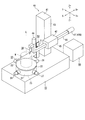
図1は、本実施形態の真円度測定機を示す斜視図、図2は、同真円度測定機の平面図である。
本実施形態の真円度測定機は、これらの図に示すように、ベース10と、このベース10上の一側に垂直軸線Lを中心に回転可能に設けられ上面に被測定物Wを載置する回転テーブル20と、検出器30と、この検出器30を垂直軸線L方向および垂直軸線Lに対して直交する方向でかつ回転テーブル20に対して接近、離間する方向へ駆動させる検出器駆動機構40と、被測定物Wの測定部位に対応して用意された複数種のスタイラス31を取出可能かつ格納可能に収容したスタイラスストッカ50と、制御装置60とを備える。
<Description of roundness measuring machine>
FIG. 1 is a perspective view showing a roundness measuring machine of this embodiment, and FIG. 2 is a plan view of the roundness measuring machine.
As shown in these drawings, the roundness measuring machine according to the present embodiment is provided with a
回転テーブル20は、回転駆動機構23によって回転駆動される構造で、ベース10に回転可能に設置された円筒状の本体21と、この本体21の上部に水平面内の直交する方向へ移動可能に設けられ上面に被測定物Wを載置する円盤状の載置板22と、この載置板22を垂直軸線Lに対して直交するX,Y軸方向へ移動させる載置板X軸移動機構24および載置板Y軸移動機構25と、載置板22のX,Y軸方向の傾きを調整する載置板X軸傾斜機構26および載置板X軸傾斜機構27を含んで構成されている。
回転駆動機構23は、回転テーブル20を回転駆動するモータ、あるいは、モータからの回転を減速器を介して回転テーブル20に伝達する機構などで構成されている。載置板X軸移動機構24および載置板Y軸移動機構25は、モータを含み、このモータの駆動により載置板22をX,Y軸方向へスライドさせる構造である。載置板X軸傾斜機構26および載置板X軸傾斜機構27は、モータを含み、このモータの駆動より載置板22をX,Y軸方向へ傾斜させる構造である。
The
The
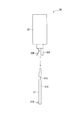
検出器30は、図3に示すように、被測定物Wに接するスタイラス31と、このスタイラス31を着脱可能に装着しスタイラス31の変位(スタイラス31の長手方向に対して直交する方向の変位)を電気信号として検出する検出器本体32とを有する。スタイラス31は、所定長さのスタイラス本体31Aと、このスタイラス本体31Aの先端に取り付けられた触針31Bと、スタイラス本体31Aの根本部分に形成された係合溝31Cとを有する。検出器本体32には、支持片32Aおよびこれに隙間を隔てて対向配置された板ばね32Bとが設けられ、この支持片32Aと板ばね32Bとの間にスタイラス31の根本部分が差込可能かつ引抜可能、つまり、着脱可能に装着されている。
As shown in FIG. 3, the
検出器駆動機構40は、ベース10上に他側に立設されたコラム41と、このコラム41に対して昇降スライダ42を上下方向(Z軸方向)へ駆動させる昇降駆動機構43と、昇降スライダ42に対してスライドアーム44を垂直軸線に対して直交する方向でかつ回転テーブル20に対して接近、離間する方向(X軸方向)へ駆動させる第1スライド駆動機構45と、スライドアーム44の先端に設けられ検出器30をスライドアーム44のスライド軸線に対して直交する方向へスライドさせる第2スライド駆動機構46と、第2スライド駆動機構46をスライドアーム44のスライド軸線を中心に旋回させる旋回駆動機構47とを備える。
The
昇降駆動機構43は、図示省略したが、昇降スライダ42を上下方向へ駆動できる機構であれば、どのような構造でもよい。例えば、コラム41に上下方向へ立設されたボールねじ軸と、このボールねじ軸を回転させるモータと、ボールねじ軸に螺合され昇降スライダ42に連結されたナット部材とを有する送り機構などでもよい。
第1スライド駆動機構45についても、図示省略したが、スライドアーム44を垂直軸線Lに対して直交する方向でかつ回転テーブル20に対して接近、離間する方向へ駆動できる機構であれば、どのような構造でもよい。例えば、スライドアーム44の長手方向に沿ってラックを形成し、このラックに噛み合うピニオンおよびこのピニオンを回転させるモータなどを昇降スライダ42内に設けた構成であってもよい。
Although the lifting
The first
第2スライド駆動機構46は、図4に示すように、スライドアーム44の先端に直角に取り付けられたケース部材46Aと、このケース部材46A内に回転可能に設けられたボールねじ軸46Bと、このボールねじ軸46Bを回転させるモータ46Cと、ボールねじ軸46Bに螺合されたナット部材46Dと、このナット部材46Dを有し検出器30を保持した検出器保持部46Eとを有する送り機構によって構成されている。なお、第2スライド駆動機構46についても、図4の構成に限られない。
As shown in FIG. 4, the second
旋回駆動機構47は、例えば、スライドアーム44の内部に回転可能に設けられ先端が第2スライド駆動機構46のケース部材46Aに連結された旋回軸(図示省略)と、この旋回軸の基端に設けられ旋回軸を旋回駆動させるモータ47Bとから構成されている。本実施形態では、図5に示すように、スタイラス31が上下方向に向かう検出器30の姿勢を0度として、検出器30の姿勢を−90度から+90度の範囲で変更可能に構成されている。
The turning
スタイラスストッカ50は、回転テーブル20および検出器駆動機構40の移動範囲によって決まる測定領域(図6に示す測定領域A)の外に、詳細には、図2に示すように回転テーブル20とコラム41との間で、スライドアーム44のスライド軸線を挟んでベース10の背面側に配置されているとともに、このスタイラスストッカ50の位置まで検出器30が移動可能に構成されている。本実施形態においては、第2スライド駆動機構46および旋回駆動機構47の動作により、検出器30が測定領域Aの外へ移動可能に構成されている。
In addition to the measurement area (measurement area A shown in FIG. 6) determined by the movement range of the rotary table 20 and the
スタイラスストッカ50は、図2および図5にも示すように、回転テーブル20とコラム41との間で、スライドアーム44のスライド軸線を挟んでベース10の背面側に配置されたL字形状のストッカ本体51と、このストッカ本体51の起立片52の上下方向一定間隔位置に形成され複数のスタイラス保持部53とから構成されている。スタイラス保持部53は、略半円形状の溝によって形成され、この溝にスタイラス31の係合溝31Cが取出可能かつ格納可能に収容されている。ここでは、標準的なスタイラス31のほかに、長さの異なるスタイラス31が収容されている。
2 and 5, the
<制御システムの説明>
本制御システムは、図7に示すように、制御装置60と、入力装置61と、表示装置62と、記憶装置63などを含んで構成されている。
記憶装置63には、測定プログラム、スタイラス自動交換プログラム、検出器自動ゲイン校正プログラムなどを記憶したプログラム記憶部63A、および、測定時に取り込んだ測定データなどを記憶するデータ記憶部63Bなどが設けられている。
制御装置60には、入力装置61、表示装置62、記憶装置63のほかに、回転駆動機構23、載置板X軸移動機構24、載置板Y軸移動機構25、載置板X軸傾斜機構26、載置板Y軸傾斜機構27、昇降駆動機構43、第1スライド駆動機構45、第2スライド駆動機構46、旋回駆動機構47、検出器30などが接続されている。また、制御装置60は、プログラム記憶部63Aに記憶された測定プログラム、スタイラス自動交換プログラム、検出器自動ゲイン校正プログラムなどに従って、各機構の駆動を制御するとともに、検出器30からの信号を取り込んで処理する機能を備える。
<Description of control system>
As shown in FIG. 7, the present control system includes a
The
In addition to the
具体的には、測定指令が与えられた際、回転駆動機構23および検出器駆動機構40の動作を制御しながら、被測定物Wの真円度等の測定を実行する測定実行手段、スタイラス自動交換指令が与えられた際、検出器駆動機構40を制御しながら、検出器30とスタイラスストッカ50との間でスタイラス交換動作を実行するスタイラス交換実行手段、検出器自動ゲイン校正指令が与えられた際、スタイラス31に予め設定された設定変位量を付与し、検出器30によって検出されるスタイラス31の変位と設定変位量とから検出器30のゲインを校正するゲイン調整手段とを備えている。
Specifically, when a measurement command is given, a measurement execution unit that measures the roundness of the workpiece W while controlling the operation of the
ここで、ゲイン調整手段は、載置板X軸移動機構24または載置板Y軸移動機構25の移動方向がX軸方向(第1移動方向)に一致するように、回転駆動機構23を動作させて回転テーブル20を回転させたのち、検出器駆動機構40を動作させて検出器30のスタイラス31を載置板22の側面に接触させ、この状態において、載置板X軸移動機構24または載置板Y軸移動機構25を予め設定された設定変位量だけ移動させたときに検出器30によって検出されるスタイラス31の変位を取り込み、この変位量と設定変位量とから検出器30のゲインを校正する動作を自動的に行う。
Here, the gain adjusting means operates the
<スタイラス交換動作の説明>
プログラム記憶部63Aに記憶されたスタイラス自動交換プログラムによって、スタイラス自動交換指令が制御装置60に与えられると、検出器駆動機構40が駆動される。つまり、昇降駆動機構43、第1スライド駆動機構45、第2スライド駆動機構46および旋回駆動機構47の駆動により、検出器30が移動され、検出器30とスタイラスストッカ50との間でスタイラス交換動作が実行される。
<Description of stylus replacement operation>
When a stylus automatic replacement command is given to the
いま、検出器30にスタイラス31が装着されている状態において、スタイラス自動交換指令が与えられると、図8に示すように、旋回駆動機構47の駆動によって検出器30が+90度旋回され、水平な姿勢に設定される。こののち、昇降駆動機構43の駆動により、検出器30がこれから格納するスタイラスストッカ50のスタイラス保持部53の高さ位置に位置決めされたのち、次の動作が実行される。
Now, when the
(A)第2スライド駆動機構46の駆動により、検出器30はY−方向へ移動され、スタイラス31の係合溝31Cがスタイラスストッカ50のスタイラス保持部53と対応する位置まで移動される。
(B)第1スライド駆動機構45の駆動により、検出器30はX+方向へ移動される。すると、スタイラス31の係合溝31Cがスタイラスストッカ50のスタイラス保持部53に収容される。
(C)第2スライド駆動機構46の駆動により、検出器30はY+方向へ移動される。すると、検出器本体32がスタイラス31をスタイラスストッカ50に残したままY+方向へ移動するから、これにより、検出器本体32のスタイラス31がスタイラスストッカ50に格納される。
(A) By driving the second
(B) When the first
(C) By driving the second
次に、検出器本体32に対して、新たなスタイラス31を装着しようとする場合、検出器本体32が新たなスタイラス31の位置に位置決めされたのち、次の動作が実行される。
(D)第2スライド駆動機構46の駆動により、検出器30はY−方向へ移動される。すると、検出器本体32に新たなスタイラス31が差し込まれる。つまり、検出器本体32に新たなスタイラス31が装着される。
(E)第1スライド駆動機構45の駆動により、検出器30はX−方向へ移動される。すると、スタイラス31の係合溝31Cがスタイラスストッカ50のスタイラス保持部53から外れる。
(F)第2スライド駆動機構46の駆動により、検出器30はY+方向へ移動され、元の位置に復帰される。こののち、旋回駆動機構47の駆動によって検出器30が垂直な姿勢に旋回されたのち、検出器自動ゲイン校正動作が実行される。
Next, when a
(D) By driving the second
(E) By driving the first
(F) By driving the second
<検出器自動ゲイン校正動作の説明>
プログラム記憶部63Aに記憶された検出器自動ゲイン校正プログラムによって、検出器自動ゲイン校正指令が制御装置60に与えられると、載置板X軸移動機構24(または載置板Y軸移動機構25)の移動方向がX軸方向(第1移動方向)に一致するように、回転駆動機構23が動作され、回転テーブル20が回転される。
こののち、図9(A)に示すように、検出器駆動機構40が駆動され、検出器30のスタイラス31が載置板22の側面に接触される。
この状態において、図9(B)に示すように、載置板X軸移動機構24によって載置板22が予め設定された設定変位量だけX軸方向へ移動される。すると、このときの移動量が検出器30によって検出される。つまり、検出器30のスタイラス31の変位量が取り込まれ、制御装置60に送られる。
制御装置60において、取り込まれた変位量と設定変位量とから検出器30のゲインを校正する。例えば、制御装置60において、取り込まれたスタイラス31の変位量が設定変位量に近似するように、検出器30からの出力を入力とする回路(DAコンバータなど)のゲインを調整することにより、検出器30のゲインを校正する。あるいは、検出器30からの変位信号をPC(パソコン)等の制御装置に取り込み、取り込んだ値が設定変位量に一致するように取り込んだ値を調整することにより、検出器30のゲインを校正する。
こののち、測定動作が実行される。
<Explanation of detector automatic gain calibration operation>
When a detector automatic gain calibration command is given to the
Thereafter, as shown in FIG. 9A, the
In this state, as shown in FIG. 9B, the
In the
Thereafter, the measurement operation is executed.
<測定動作の説明>
プログラム記憶部63Aに記憶された測定プログラムによって、測定指令が制御装置60に与えられると、検出器駆動機構40が駆動される。つまり、昇降駆動機構43および第1スライド駆動機構45の駆動により、検出器30が被測定物Wに接近する方向へ移動され、検出器30のスタイラス31が被測定物Wに接触される。
この状態において、回転テーブル20が回転駆動される。すると、被測定物Wの真円度に応じて、検出器30のスタイラス31が変位されるから、そのスタイラス31の変位が検出器本体32によって電気信号として検出されたのち、制御装置60に取り込まれる。制御装置60は、取り込んだ測定データをデータ記憶部63Bに記憶したのち、こられのデータから真円度を演算し、その結果を表示装置62に表示し、かつ、必要に応じてプリントアウトする。
<Description of measurement operation>
When a measurement command is given to the
In this state, the rotary table 20 is driven to rotate. Then, since the
<実施形態の効果>
(1)スタイラス自動交換指令が与えられると、検出器駆動機構40の動作により、検出器本体32とスタイラスストッカ50との間でスタイラス交換動作が実行される。
従って、被測定物Wの測定部位形状に応じて、スタイラス交換動作を指令するようにしておけば、検出器本体32とスタイラスストッカ50との間でスタイラス交換動作が自動的に実行されるため、測定作業を中断することなく連続的に行うことができる。そのため、測定者への負担を軽減できるとともに、測定作業を効率化できる。
<Effect of embodiment>
(1) When an automatic stylus replacement command is given, a stylus replacement operation is performed between the detector
Therefore, if the stylus replacement operation is commanded according to the shape of the measurement site of the workpiece W, the stylus replacement operation is automatically executed between the detector
(2)検出器自動ゲイン校正指令が与えられると、スタイラス31に予め設定された設定変位量が付与され、検出器30によって検出されるスタイラス31の変位と設定変位量とから検出器30のゲインが校正される。
従って、スタイラス交換動作を行ったのち、検出器自動ゲイン校正指令を与えるよう構成しておけば、スタイラス31の交換動作後に、検出器30のゲイン校正動作が自動的に実行されるから、スタイラス31の交換動作および検出器30のゲイン校正動作を測定作業を中断することなく連続的かつ自動的に行うことができる。そのため、測定者への負担を軽減できるとともに、測定作業を効率化できる。
(2) When a detector automatic gain calibration command is given, a preset set displacement amount is given to the
Accordingly, if the detector automatic gain calibration command is given after the stylus exchange operation, the gain calibration operation of the
(3)測定指令が与えられると、検出器駆動機構40の動作により検出器30のスタイラス31が被測定物Wに接触され、この状態において、回転テーブル20が回動動作されることにより、被測定物Wの真円度等の測定が実行される。
従って、スタイラス自動交換動作、検出器自動ゲイン校正動作および測定動作が連続的に実行されるから、作業能率の一層の向上が期待できる。
(3) When a measurement command is given, the
Therefore, since the automatic stylus exchange operation, the automatic detector gain calibration operation, and the measurement operation are continuously performed, further improvement in work efficiency can be expected.
(4)スタイラスストッカ50は、回転テーブル20および検出器駆動機構40の移動範囲によって決まる測定領域Aの外に配置され、また、検出器駆動機構40は、検出器30を測定領域の外へ移動可能に構成されているから、スタイラスストッカ50が測定領域を制限することがない。
(4) The
(5)検出器駆動機構40には、スライドアーム44の先端に設けられ検出器30をスライドアーム44のスライド軸線に対して直交する方向へスライドさせる第2スライド駆動機構46と、第2スライド駆動機構46をスライドアーム44のスライド軸線を中心に旋回させる旋回駆動機構47とが含まれているから、まず、旋回駆動機構47によって第2スライド駆動機構46をスライドアーム44のスライド軸線を中心に90度旋回させて検出器30の姿勢を水平に変更したのち、第2スライド駆動機構46によって検出器30をスライドアーム44のスライド軸線に対して直交する方向へスライドさせると、検出器30が測定領域Aの外に配置されたスタイラスストッカ50へ移動される。従って、真円度測定動作に支障を与えることなく、比較的簡易な構成で、検出器30を測定領域Aの外に配置されたスタイラスストッカ50へアプローチできる。
(5) The
(6)スタイラスストッカ50が、回転テーブル20とコラム41との間で、スライドアーム44のスライド軸線を挟んでベース10の背面側に配置されているから、ベース10の正面側から見た視界を遮ることがないため、作業者は測定作業を目視で確認しながら測定作業を行うことができる。
(6) Since the
(7)スタイラス31が上下方向に向かう検出器30の姿勢を0度として、検出器30の姿勢を−90度から+90度の範囲で変更可能に構成されているから、例えば、検出器30が+90度の姿勢のときにスタイラス交換動作が行える構成とすれば、検出器30が−90度の姿勢においては被測定物の真円度測定を実行できる。従って、被測定物の形状などに応じて検出器の姿勢を適宜変更して測定を実行できる。
(7) Since the attitude of the
<変形例>
本発明は、前述の実施形態に限定されるものでなく、本発明の目的を達成できる範囲での変形、改良などは本考案に含まれる。
前記実施形態では、検出器自動ゲイン校正指令が制御装置60に与えられると、載置板X軸移動機構24または載置板Y軸移動機構25の移動方向がX軸方向(第1移動方向)に一致するように、回転テーブル20が回転されたのち、検出器30のスタイラス31が載置板22の側面に接触された状態において、載置板X軸移動機構24または載置板Y軸移動機構25が予め設定された設定変位量だけ移動されることにより、検出器30のゲインを校正するようにしたが、これに限られない。
例えば、図9(B)の状態において、載置板X軸移動機構24または載置板Y軸移動機構25を設定変位量だけ移動させるのではなく、第1スライド駆動機構45を設定変位量だけ移動させてもよい。
<Modification>
The present invention is not limited to the above-described embodiments, and modifications, improvements and the like within the scope that can achieve the object of the present invention are included in the present invention.
In the embodiment, when the detector automatic gain calibration command is given to the
For example, in the state of FIG. 9B, the first
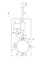
あるいは、真円度測定機を図10に示すように構成し、図11に示すように検出器校正動作を行うようにしてもよい。
図10に示す真円度測定機では、回転テーブル20の載置板22の外周縁の一部に外周縁からの切欠深さが設定変位量に相当する切欠き22Aが形成されている。ゲイン調整手段は、図11(A)に示すように、第1スライド駆動機構45を動作させて検出器30のスタイラス31を載置板22の側面に接触させ、この状態において、図11(B)に示すように、回転駆動機構23を作動させ、このときに検出器30によって検出されるスタイラスの変位を取り込み、この変位量と設定変位量とから検出器のゲインを校正する。
Alternatively, the roundness measuring machine may be configured as shown in FIG. 10, and the detector calibration operation may be performed as shown in FIG.
In the roundness measuring machine shown in FIG. 10, a
すなわち、検出器駆動機構40が動作されて検出器30のスタイラス31が載置板22の側面に接触されたのち、この状態において、回転駆動機構23を作動される。すると、載置板22の外周縁の一部に形成された切欠き22Aが検出器30によって検出される。つまり、検出器30のスタイラス31の変位が取り込まれ、この変位量と設定変位量とから検出器30のゲインが校正される。
従って、この構成でも、上記と同様に、従来の校正用治具や校正用マスタを用いなくてもよいので、これの回転テーブル20上へのセットおよび取り外しに伴う作業がなく、測定作業をより効率化できるとともに、載置板X軸移動機構24または載置板Y軸移動機構25も必要なく、これらの移動方向が第1スライド駆動機構45の移動方向(第1移動方向)に一致するように、回転駆動機構23を動作させて回転テーブル20を回転動作させる必要もないので、より簡易化、迅速化できる。
That is, after the
Accordingly, in this configuration as well, the conventional calibration jig and calibration master do not have to be used, so that there is no work associated with setting and removing the rotary table 20 and the measurement work is further improved. The mounting plate
前記実施形態では、スタイラスストッカ50が、ストッカ本体51に半円形状のスタイラス保持部53を上下方向に間隔を隔てて形成し、これに複数種のスタイラス31を水平な姿勢で保持するようにしたが、これに限られない。例えば、スタイラス保持部53を水平方向に間隔を隔てて形成し、これにスタイラス31を垂直な姿勢で保持するようにしてもよい。
In the embodiment, the
前記実施形態において、検出器本体32とスタイラス31とを、マグネットによって着脱可能に結合するようにしてもよい。あるいは、磁気に限らず、他の構成でもよい。例えば、エアーの吸引によって、検出器本体32とスタイラス31と着脱可能に保持する構造であってもよく、あるいは、どちらか一方に複数の挟持爪を設け、他方に挟持爪に挟持される挟持部を設けた構成であってもよい。
In the embodiment, the detector
前記実施形態では、検出器30をX軸方向およびZ軸方向へ移動可能に構成したが、これに限られない。
In the embodiment, the
本発明は、スタイラスの交換から測定までを連続的に行う真円度測定機に利用できる。 INDUSTRIAL APPLICABILITY The present invention can be used for a roundness measuring machine that continuously performs stylus replacement and measurement.
10…ベース、
20…回転テーブル、
21…本体、
22…載置板、
22A…切欠き、
23…回転駆動機構、
24…載置板X軸移動機構(載置板移動機構)、
25…載置板Y軸移動機構(載置板移動機構)、
30…検出器、
31…スタイラス、
32…検出器本体、
40…検出器駆動機構、
41…コラム、
42…昇降スライダ、
43…昇降駆動機構、
44…スライドアーム、
45…第1スライド駆動機構、
46…第2スライド駆動機構、
47…旋回駆動機構、
50…スタイラスストッカ、
60…制御装置、
A…測定領域、
L…垂直軸線、
W…被測定物。
10 ... Base,
20 ... rotary table,
21 ... the body,
22 ... mounting plate,
22A ... Notch,
23 ... Rotation drive mechanism,
24: Mounting plate X-axis moving mechanism (mounting plate moving mechanism),
25. Mounting plate Y-axis moving mechanism (mounting plate moving mechanism),
30 ... detector,
31 ... Stylus,
32 ... the detector body,
40. Detector drive mechanism,
41 ... Column,
42: Elevating slider,
43 ... Elevating drive mechanism,
44 ... slide arm,
45. First slide drive mechanism,
46. Second slide drive mechanism,
47. Turning drive mechanism,
50 ... Stylus stocker,
60 ... Control device,
A: Measurement area,
L ... vertical axis,
W: Object to be measured.
Claims (5)
前記被測定物の測定部位に対応して用意された複数種のスタイラスを取出可能かつ格納可能に収容したスタイラスストッカと、制御装置とを備え、
前記制御装置は、測定指令が与えられた際、前記回転駆動機構および前記検出器駆動機構の動作を制御しながら、前記被測定物の真円度測定を実行する測定実行手段と、
スタイラス自動交換指令が与えられた際、前記検出器駆動機構を制御しながら、前記検出器と前記スタイラスストッカとの間でスタイラス交換動作を実行するスタイラス交換実行手段と、
検出器自動ゲイン校正指令が与えられた際、前記スタイラスに予め設定された設定変位量を付与し、前記検出器によって検出される前記スタイラスの変位と前記設定変位量とから前記検出器のゲインを校正するゲイン調整手段とを備える、ことを特徴とする真円度測定機。 A base, a rotary table provided on the base so as to be rotatable about a vertical axis, and an object to be measured placed on the upper surface; a rotary drive mechanism for rotating the rotary table; a stylus in contact with the object to be measured; A detector having a detector main body that detachably mounts the stylus and outputs the displacement of the stylus as an electrical signal, and the detector is orthogonal to the vertical axis and approaches and separates from the rotary table In a roundness measuring machine having a first moving direction and a detector driving mechanism for driving in a second moving direction parallel to the vertical axis,
A stylus stocker which accommodates a plurality of types of styluses prepared corresponding to the measurement site of the object to be measured and is storable, and a control device;
The control device, when a measurement command is given, measurement execution means for measuring the roundness of the device under test while controlling the operation of the rotation drive mechanism and the detector drive mechanism;
Stylus replacement execution means for performing a stylus replacement operation between the detector and the stylus stocker while controlling the detector driving mechanism when a stylus automatic replacement command is given;
When a detector automatic gain calibration command is given, a preset set displacement amount is given to the stylus, and the gain of the detector is determined from the displacement of the stylus detected by the detector and the set displacement amount. A roundness measuring machine comprising gain adjusting means for calibrating.
前記回転テーブルは、前記ベース上に垂直軸線を中心に回転可能に設けられた本体と、この本体の上部に設けられ上面に被測定物を載置する円盤状の載置板と、この載置板を前記垂直軸線に対して直交する方向へ移動させる載置板移動機構とを含んで構成され、
前記ゲイン調整手段は、前記載置板移動機構の移動方向が前記第1移動方向に一致するように、前記回転駆動機構を動作させて前記回転テーブルを回転させたのち、前記検出器駆動機構を動作させて前記検出器のスタイラスを前記載置板の側面に接触させ、この状態において、前記載置板移動機構を予め設定された設定変位量だけ移動させたときに前記検出器によって検出される前記スタイラスの変位を取り込み、この変位量と前記設定変位量とから前記検出器のゲインを校正する、ことを特徴とする真円度測定機。 In the roundness measuring machine according to claim 1,
The rotary table includes a main body provided on the base so as to be rotatable about a vertical axis, a disk-like mounting plate provided on an upper surface of the main body, and a measurement object on the upper surface, and the mounting table. A mounting plate moving mechanism that moves the plate in a direction perpendicular to the vertical axis,
The gain adjusting means operates the rotary drive mechanism to rotate the rotary table so that the moving direction of the mounting plate moving mechanism matches the first moving direction, and then rotates the detector drive mechanism. The detector is operated to bring the detector stylus into contact with the side surface of the mounting plate. In this state, the detector is detected when the mounting plate moving mechanism is moved by a preset set displacement amount. A roundness measuring machine that takes in the displacement of the stylus and calibrates the gain of the detector from the displacement amount and the set displacement amount.
前記回転テーブルは、前記ベース上に垂直軸線を中心に回転可能に設けられた本体と、この本体の上部に設けられ上面に被測定物を載置する円盤状の載置板とを含んで構成され、
前記ゲイン調整手段は、前記検出器駆動機構を動作させて前記検出器のスタイラスを前記載置板の側面に接触させ、この状態において、前記検出器駆動機構を前記第1移動方向へ予め設定された設定変位量だけ移動させたときに前記検出器によって検出される前記スタイラスの変位を取り込み、この変位量と前記設定変位量とから前記検出器のゲインを校正する、ことを特徴とする真円度測定機。 In the roundness measuring machine according to claim 1,
The rotary table includes a main body provided on the base so as to be rotatable about a vertical axis, and a disk-like mounting plate provided on an upper surface of the main body for mounting an object to be measured. And
The gain adjusting means operates the detector driving mechanism to bring the detector stylus into contact with the side surface of the mounting plate. In this state, the detector driving mechanism is preset in the first movement direction. A perfect circle, which takes in the displacement of the stylus detected by the detector when moved by the set displacement amount and calibrates the gain of the detector from the displacement amount and the set displacement amount. Degree measuring machine.
前記回転テーブルは、前記ベース上に垂直軸線を中心に回転可能に設けられた本体と、この本体の上部に設けられ上面に被測定物を載置する円盤状の載置板と、この載置板を前記垂直軸線に対して直交する方向へ移動させる載置板移動機構とを含んで構成され、前記載置板の外周縁の一部には外周縁からの切欠深さが前記設定変位量に相当する切欠きが形成され、
前記ゲイン調整手段は、前記検出器駆動機構を動作させて前記検出器のスタイラスを前記載置板の側面に接触させ、この状態において、前記回転駆動機構を作動させたときに前記検出器によって検出される前記スタイラスの変位を取り込み、この変位量と前記設定変位量とから前記検出器のゲインを校正する、ことを特徴とする真円度測定機。 In the roundness measuring machine according to claim 1,
The rotary table includes a main body provided on the base so as to be rotatable about a vertical axis, a disk-like mounting plate provided on an upper surface of the main body, and a measurement object on the upper surface, and the mounting table. A mounting plate moving mechanism that moves the plate in a direction orthogonal to the vertical axis, and the notch depth from the outer periphery of the mounting plate has a notch depth from the outer peripheral edge. A notch corresponding to is formed,
The gain adjusting means operates the detector driving mechanism to bring the stylus of the detector into contact with the side surface of the mounting plate. In this state, the detector detects when the rotational driving mechanism is operated. The roundness measuring machine is characterized in that it takes in the displacement of the stylus and calibrates the gain of the detector from the displacement amount and the set displacement amount.
前記スタイラスストッカは、前記回転テーブルおよび前記検出器駆動機構の移動範囲によって決まる測定領域の外に配置され、
前記検出器駆動機構は、前記ベース上に立設されたコラムと、このコラムに対して昇降スライダを上下方向へ駆動させる昇降駆動機構と、前記昇降スライダに対してスライドアームを前記垂直軸線に対して直交しかつ前記回転テーブルに対して接近、離間する方向へ駆動させる第1スライド駆動機構と、前記スライドアームの先端に設けられ前記検出器を前記スライドアームのスライド軸線に対して直交する方向へスライドさせる第2スライド駆動機構と、前記第2スライド駆動機構を前記スライドアームのスライド軸線を中心に旋回させる旋回駆動機構とを備え、
前記第2スライド駆動機構および前記旋回駆動機構の動作により、前記検出器が前記測定領域の外へ移動可能に構成されている、ことを特徴とする真円度測定機。 In the roundness measuring machine according to any one of claims 1 to 4,
The stylus stocker is disposed outside a measurement region determined by a moving range of the rotary table and the detector driving mechanism,
The detector driving mechanism includes a column erected on the base, an elevating drive mechanism for driving the elevating slider in the vertical direction with respect to the column, and a slide arm with respect to the vertical axis with respect to the elevating slider. And a first slide drive mechanism for driving in a direction toward and away from the rotary table, and a detector provided at the tip of the slide arm in a direction perpendicular to the slide axis of the slide arm. A second slide drive mechanism for sliding, and a turning drive mechanism for turning the second slide drive mechanism about the slide axis of the slide arm,
The roundness measuring machine, wherein the detector is configured to be movable out of the measurement region by the operations of the second slide drive mechanism and the turning drive mechanism.
Priority Applications (1)
| Application Number | Priority Date | Filing Date | Title |
|---|---|---|---|
| JP2010074846A JP5324510B2 (en) | 2010-03-29 | 2010-03-29 | Roundness measuring machine |
Applications Claiming Priority (1)
| Application Number | Priority Date | Filing Date | Title |
|---|---|---|---|
| JP2010074846A JP5324510B2 (en) | 2010-03-29 | 2010-03-29 | Roundness measuring machine |
Publications (2)
| Publication Number | Publication Date |
|---|---|
| JP2011208994A true JP2011208994A (en) | 2011-10-20 |
| JP5324510B2 JP5324510B2 (en) | 2013-10-23 |
Family
ID=44940230
Family Applications (1)
| Application Number | Title | Priority Date | Filing Date |
|---|---|---|---|
| JP2010074846A Active JP5324510B2 (en) | 2010-03-29 | 2010-03-29 | Roundness measuring machine |
Country Status (1)
| Country | Link |
|---|---|
| JP (1) | JP5324510B2 (en) |
Cited By (11)
| Publication number | Priority date | Publication date | Assignee | Title |
|---|---|---|---|---|
| DE102013220943A1 (en) | 2012-10-18 | 2014-04-24 | Mitutoyo Corporation | Profile measuring device, setting method for profile measuring device and profile measuring method |
| JP5943099B1 (en) * | 2015-01-28 | 2016-06-29 | 株式会社東京精密 | Roundness measuring device |
| JP2016148685A (en) * | 2016-05-24 | 2016-08-18 | 株式会社東京精密 | Circularity measuring apparatus |
| KR20180047369A (en) * | 2016-10-31 | 2018-05-10 | 창원대학교 산학협력단 | A compound profile meter |
| JP2019536032A (en) * | 2016-11-16 | 2019-12-12 | レニショウ パブリック リミテッド カンパニーRenishaw Public Limited Company | Coordinate positioning apparatus and operation method |
| CN111043995A (en) * | 2018-10-15 | 2020-04-21 | 北京福田康明斯发动机有限公司 | Method and device for calibrating rotating table of three-coordinate measuring machine |
| KR20210026413A (en) * | 2019-08-30 | 2021-03-10 | 일륭기공(주) | Inspection devices of lever for steering |
| CN112697087A (en) * | 2020-12-04 | 2021-04-23 | 戴狄凯 | Casing monitoring device of strong acid fluid valve |
| CN114234866A (en) * | 2021-12-14 | 2022-03-25 | 大连德迈仕精密科技股份有限公司 | Automobile air conditioner compressor spindle circle run-out detection device and detection method thereof |
| CN116045885A (en) * | 2023-03-03 | 2023-05-02 | 长沙迈科轴承有限公司 | Outer diameter roundness detection device for axle bearing production |
| CN118392090A (en) * | 2024-06-25 | 2024-07-26 | 七海测量技术(深圳)有限公司 | Measuring head conversion device of three-coordinate measuring machine |
Citations (4)
| Publication number | Priority date | Publication date | Assignee | Title |
|---|---|---|---|---|
| JPH09269224A (en) * | 1996-03-29 | 1997-10-14 | Tokyo Seimitsu Co Ltd | Detector sensitivity calibrating method and device for roundness measuring apparatus |
| JP2004317159A (en) * | 2003-04-11 | 2004-11-11 | Mitsutoyo Corp | Reference holder for roundness measuring machines |
| JP3141561U (en) * | 2008-02-26 | 2008-05-08 | 株式会社ミツトヨ | Surface roughness measuring device |
| JP2009069067A (en) * | 2007-09-14 | 2009-04-02 | Tokyo Seimitsu Co Ltd | Shape analysis apparatus and shape analysis program |
-
2010
- 2010-03-29 JP JP2010074846A patent/JP5324510B2/en active Active
Patent Citations (4)
| Publication number | Priority date | Publication date | Assignee | Title |
|---|---|---|---|---|
| JPH09269224A (en) * | 1996-03-29 | 1997-10-14 | Tokyo Seimitsu Co Ltd | Detector sensitivity calibrating method and device for roundness measuring apparatus |
| JP2004317159A (en) * | 2003-04-11 | 2004-11-11 | Mitsutoyo Corp | Reference holder for roundness measuring machines |
| JP2009069067A (en) * | 2007-09-14 | 2009-04-02 | Tokyo Seimitsu Co Ltd | Shape analysis apparatus and shape analysis program |
| JP3141561U (en) * | 2008-02-26 | 2008-05-08 | 株式会社ミツトヨ | Surface roughness measuring device |
Cited By (21)
| Publication number | Priority date | Publication date | Assignee | Title |
|---|---|---|---|---|
| DE102013220943A1 (en) | 2012-10-18 | 2014-04-24 | Mitutoyo Corporation | Profile measuring device, setting method for profile measuring device and profile measuring method |
| US9316476B2 (en) | 2012-10-18 | 2016-04-19 | Mitutoyo Corporation | Profile measuring instrument, adjusting method for profile measuring instrument, and profile measuring method |
| DE102013220943B4 (en) | 2012-10-18 | 2024-04-04 | Mitutoyo Corporation | Profile measuring device, setting method for profile measuring device and profile measuring method |
| JP5943099B1 (en) * | 2015-01-28 | 2016-06-29 | 株式会社東京精密 | Roundness measuring device |
| WO2016121490A1 (en) * | 2015-01-28 | 2016-08-04 | 株式会社東京精密 | Roundness measurement device |
| JP2016148685A (en) * | 2016-05-24 | 2016-08-18 | 株式会社東京精密 | Circularity measuring apparatus |
| KR20180047369A (en) * | 2016-10-31 | 2018-05-10 | 창원대학교 산학협력단 | A compound profile meter |
| KR101915948B1 (en) | 2016-10-31 | 2019-01-30 | 창원대학교 산학협력단 | A compound profile meter |
| US11402201B2 (en) | 2016-11-16 | 2022-08-02 | Renishaw Plc | Coordinate positioning apparatus and method of operation |
| JP7105769B2 (en) | 2016-11-16 | 2022-07-25 | レニショウ パブリック リミテッド カンパニー | Coordinate positioning device and method of operation |
| JP2019536032A (en) * | 2016-11-16 | 2019-12-12 | レニショウ パブリック リミテッド カンパニーRenishaw Public Limited Company | Coordinate positioning apparatus and operation method |
| CN111043995B (en) * | 2018-10-15 | 2022-05-27 | 北京福田康明斯发动机有限公司 | Method and device for calibrating rotating table of three-coordinate measuring machine |
| CN111043995A (en) * | 2018-10-15 | 2020-04-21 | 北京福田康明斯发动机有限公司 | Method and device for calibrating rotating table of three-coordinate measuring machine |
| KR20210026413A (en) * | 2019-08-30 | 2021-03-10 | 일륭기공(주) | Inspection devices of lever for steering |
| KR102273248B1 (en) * | 2019-08-30 | 2021-07-06 | 일륭기공(주) | Inspection devices of lever for steering |
| CN112697087A (en) * | 2020-12-04 | 2021-04-23 | 戴狄凯 | Casing monitoring device of strong acid fluid valve |
| CN112697087B (en) * | 2020-12-04 | 2022-12-06 | 安徽精尼流体机械设备有限公司 | Casing monitoring device of strong acid fluid valve |
| CN114234866A (en) * | 2021-12-14 | 2022-03-25 | 大连德迈仕精密科技股份有限公司 | Automobile air conditioner compressor spindle circle run-out detection device and detection method thereof |
| CN114234866B (en) * | 2021-12-14 | 2024-02-20 | 大连德迈仕精密科技股份有限公司 | Device and method for detecting circular runout of main shaft of automobile air conditioner compressor |
| CN116045885A (en) * | 2023-03-03 | 2023-05-02 | 长沙迈科轴承有限公司 | Outer diameter roundness detection device for axle bearing production |
| CN118392090A (en) * | 2024-06-25 | 2024-07-26 | 七海测量技术(深圳)有限公司 | Measuring head conversion device of three-coordinate measuring machine |
Also Published As
| Publication number | Publication date |
|---|---|
| JP5324510B2 (en) | 2013-10-23 |
Similar Documents
| Publication | Publication Date | Title |
|---|---|---|
| JP5324510B2 (en) | Roundness measuring machine | |
| JP5451180B2 (en) | Roundness measuring machine | |
| JP6518421B2 (en) | Roundness measuring machine and control method thereof | |
| JP3141561U (en) | Surface roughness measuring device | |
| CN102042813B (en) | Surface texture measuring machine and a surface texture measuring method | |
| JP4163545B2 (en) | Reference jig for roundness measuring machine | |
| EP2253930B1 (en) | Form measuring instrument, and calibration method and calibration program therefor | |
| JP6113998B2 (en) | Shape measuring machine, method for adjusting shape measuring machine, and shape measuring method | |
| CN101886921B (en) | Measurement method and measurement accessory for zero point calibration of gear measuring center | |
| JP5485676B2 (en) | Surface texture measuring machine | |
| JP2006231509A (en) | Method for measuring program control type machine tool | |
| JP5943099B1 (en) | Roundness measuring device | |
| JP2002340503A (en) | Method for adjusting relative attitude of object to be measured for surface properties measuring machine | |
| EP2312263A1 (en) | Offset Amount Calibrating Method and Surface Profile Measuring Machine | |
| JP2009115527A (en) | Stylus, shape measuring instrument, and part program | |
| JP2018036130A (en) | Circularity measuring instrument | |
| JP5971445B1 (en) | Roundness measuring device | |
| JP2000266534A (en) | Surface profile measuring apparatus, inclination adjuster therefor and method for adjusting attitude of object | |
| JP5000894B2 (en) | Surface texture measuring machine | |
| JP2012190918A (en) | Surface roughness measuring instrument | |
| JP2006194739A (en) | Device and method for measuring vibration of measured object | |
| JP2009262241A (en) | Alignment method, alignment support apparatus, and alignment support program | |
| JP5350170B2 (en) | Surface texture measuring machine | |
| JP6726566B2 (en) | Drive unit tilt adjusting method and drive unit tilt adjusting program | |
| JP2004212147A (en) | Groove measuring device |
Legal Events
| Date | Code | Title | Description |
|---|---|---|---|
| A621 | Written request for application examination |
Free format text: JAPANESE INTERMEDIATE CODE: A621 Effective date: 20130208 |
|
| A977 | Report on retrieval |
Free format text: JAPANESE INTERMEDIATE CODE: A971007 Effective date: 20130709 |
|
| TRDD | Decision of grant or rejection written | ||
| A01 | Written decision to grant a patent or to grant a registration (utility model) |
Free format text: JAPANESE INTERMEDIATE CODE: A01 Effective date: 20130716 |
|
| A61 | First payment of annual fees (during grant procedure) |
Free format text: JAPANESE INTERMEDIATE CODE: A61 Effective date: 20130718 |
|
| R150 | Certificate of patent or registration of utility model |
Ref document number: 5324510 Country of ref document: JP Free format text: JAPANESE INTERMEDIATE CODE: R150 Free format text: JAPANESE INTERMEDIATE CODE: R150 |
|
| R250 | Receipt of annual fees |
Free format text: JAPANESE INTERMEDIATE CODE: R250 |
|
| R250 | Receipt of annual fees |
Free format text: JAPANESE INTERMEDIATE CODE: R250 |
|
| R250 | Receipt of annual fees |
Free format text: JAPANESE INTERMEDIATE CODE: R250 |
|
| R250 | Receipt of annual fees |
Free format text: JAPANESE INTERMEDIATE CODE: R250 |