WO2016117243A1 - 樹脂シートの製造方法 - Google Patents
樹脂シートの製造方法 Download PDFInfo
- Publication number
- WO2016117243A1 WO2016117243A1 PCT/JP2015/085109 JP2015085109W WO2016117243A1 WO 2016117243 A1 WO2016117243 A1 WO 2016117243A1 JP 2015085109 W JP2015085109 W JP 2015085109W WO 2016117243 A1 WO2016117243 A1 WO 2016117243A1
- Authority
- WO
- WIPO (PCT)
- Prior art keywords
- resin
- resin composition
- layer
- varnish
- mass
- Prior art date
- Legal status (The legal status is an assumption and is not a legal conclusion. Google has not performed a legal analysis and makes no representation as to the accuracy of the status listed.)
- Ceased
Links
Images


Classifications
-
- B—PERFORMING OPERATIONS; TRANSPORTING
- B32—LAYERED PRODUCTS
- B32B—LAYERED PRODUCTS, i.e. PRODUCTS BUILT-UP OF STRATA OF FLAT OR NON-FLAT, e.g. CELLULAR OR HONEYCOMB, FORM
- B32B37/00—Methods or apparatus for laminating, e.g. by curing or by ultrasonic bonding
- B32B37/14—Methods or apparatus for laminating, e.g. by curing or by ultrasonic bonding characterised by the properties of the layers
- B32B37/24—Methods or apparatus for laminating, e.g. by curing or by ultrasonic bonding characterised by the properties of the layers with at least one layer not being coherent before laminating, e.g. made up from granular material sprinkled onto a substrate
-
- B—PERFORMING OPERATIONS; TRANSPORTING
- B05—SPRAYING OR ATOMISING IN GENERAL; APPLYING FLUENT MATERIALS TO SURFACES, IN GENERAL
- B05D—PROCESSES FOR APPLYING FLUENT MATERIALS TO SURFACES, IN GENERAL
- B05D1/00—Processes for applying liquids or other fluent materials
- B05D1/36—Successively applying liquids or other fluent materials, e.g. without intermediate treatment
-
- B—PERFORMING OPERATIONS; TRANSPORTING
- B05—SPRAYING OR ATOMISING IN GENERAL; APPLYING FLUENT MATERIALS TO SURFACES, IN GENERAL
- B05D—PROCESSES FOR APPLYING FLUENT MATERIALS TO SURFACES, IN GENERAL
- B05D7/00—Processes, other than flocking, specially adapted for applying liquids or other fluent materials to particular surfaces or for applying particular liquids or other fluent materials
- B05D7/50—Multilayers
- B05D7/52—Two layers
-
- B—PERFORMING OPERATIONS; TRANSPORTING
- B32—LAYERED PRODUCTS
- B32B—LAYERED PRODUCTS, i.e. PRODUCTS BUILT-UP OF STRATA OF FLAT OR NON-FLAT, e.g. CELLULAR OR HONEYCOMB, FORM
- B32B27/00—Layered products comprising a layer of synthetic resin
-
- B—PERFORMING OPERATIONS; TRANSPORTING
- B32—LAYERED PRODUCTS
- B32B—LAYERED PRODUCTS, i.e. PRODUCTS BUILT-UP OF STRATA OF FLAT OR NON-FLAT, e.g. CELLULAR OR HONEYCOMB, FORM
- B32B27/00—Layered products comprising a layer of synthetic resin
- B32B27/06—Layered products comprising a layer of synthetic resin as the main or only constituent of a layer, which is next to another layer of the same or of a different material
- B32B27/08—Layered products comprising a layer of synthetic resin as the main or only constituent of a layer, which is next to another layer of the same or of a different material of synthetic resin
-
- B—PERFORMING OPERATIONS; TRANSPORTING
- B32—LAYERED PRODUCTS
- B32B—LAYERED PRODUCTS, i.e. PRODUCTS BUILT-UP OF STRATA OF FLAT OR NON-FLAT, e.g. CELLULAR OR HONEYCOMB, FORM
- B32B38/00—Ancillary operations in connection with laminating processes
- B32B38/16—Drying; Softening; Cleaning
- B32B38/164—Drying
-
- C—CHEMISTRY; METALLURGY
- C08—ORGANIC MACROMOLECULAR COMPOUNDS; THEIR PREPARATION OR CHEMICAL WORKING-UP; COMPOSITIONS BASED THEREON
- C08J—WORKING-UP; GENERAL PROCESSES OF COMPOUNDING; AFTER-TREATMENT NOT COVERED BY SUBCLASSES C08B, C08C, C08F, C08G or C08H
- C08J5/00—Manufacture of articles or shaped materials containing macromolecular substances
- C08J5/18—Manufacture of films or sheets
-
- H—ELECTRICITY
- H05—ELECTRIC TECHNIQUES NOT OTHERWISE PROVIDED FOR
- H05K—PRINTED CIRCUITS; CASINGS OR CONSTRUCTIONAL DETAILS OF ELECTRIC APPARATUS; MANUFACTURE OF ASSEMBLAGES OF ELECTRICAL COMPONENTS
- H05K1/00—Printed circuits
- H05K1/02—Details
- H05K1/03—Use of materials for the substrate
-
- H—ELECTRICITY
- H05—ELECTRIC TECHNIQUES NOT OTHERWISE PROVIDED FOR
- H05K—PRINTED CIRCUITS; CASINGS OR CONSTRUCTIONAL DETAILS OF ELECTRIC APPARATUS; MANUFACTURE OF ASSEMBLAGES OF ELECTRICAL COMPONENTS
- H05K3/00—Apparatus or processes for manufacturing printed circuits
- H05K3/46—Manufacturing multilayer circuits
-
- B—PERFORMING OPERATIONS; TRANSPORTING
- B29—WORKING OF PLASTICS; WORKING OF SUBSTANCES IN A PLASTIC STATE IN GENERAL
- B29C—SHAPING OR JOINING OF PLASTICS; SHAPING OF MATERIAL IN A PLASTIC STATE, NOT OTHERWISE PROVIDED FOR; AFTER-TREATMENT OF THE SHAPED PRODUCTS, e.g. REPAIRING
- B29C41/00—Shaping by coating a mould, core or other substrate, i.e. by depositing material and stripping-off the shaped article; Apparatus therefor
- B29C41/02—Shaping by coating a mould, core or other substrate, i.e. by depositing material and stripping-off the shaped article; Apparatus therefor for making articles of definite length, i.e. discrete articles
- B29C41/22—Making multilayered or multicoloured articles
-
- B—PERFORMING OPERATIONS; TRANSPORTING
- B32—LAYERED PRODUCTS
- B32B—LAYERED PRODUCTS, i.e. PRODUCTS BUILT-UP OF STRATA OF FLAT OR NON-FLAT, e.g. CELLULAR OR HONEYCOMB, FORM
- B32B37/00—Methods or apparatus for laminating, e.g. by curing or by ultrasonic bonding
- B32B37/14—Methods or apparatus for laminating, e.g. by curing or by ultrasonic bonding characterised by the properties of the layers
- B32B37/24—Methods or apparatus for laminating, e.g. by curing or by ultrasonic bonding characterised by the properties of the layers with at least one layer not being coherent before laminating, e.g. made up from granular material sprinkled onto a substrate
- B32B2037/243—Coating
-
- B—PERFORMING OPERATIONS; TRANSPORTING
- B32—LAYERED PRODUCTS
- B32B—LAYERED PRODUCTS, i.e. PRODUCTS BUILT-UP OF STRATA OF FLAT OR NON-FLAT, e.g. CELLULAR OR HONEYCOMB, FORM
- B32B2457/00—Electrical equipment
- B32B2457/08—PCBs, i.e. printed circuit boards
Definitions
- the present invention relates to a method for producing a resin sheet. Furthermore, the present invention relates to a resin sheet, a printed wiring board manufacturing method, a printed wiring board, and a semiconductor device.
- the insulating layer is generally formed by laminating a resin sheet including a resin composition layer on an inner layer substrate and curing the resin composition layer.
- Patent Document 1 discloses a resin sheet including a plurality of resin composition layers and including a layer having a high ratio of resin components as the resin composition layer to be bonded to the conductor layer. Has been.
- the present inventors have a case where delamination occurs when exposed to a high temperature environment such as during reflow. I found that there is.
- the present inventors also find that it is difficult to control the thickness of each layer, which may result in an insulating layer having poor roughness and peel strength stability. I found it.
- An object of the present invention is to provide a method for producing a resin sheet capable of suppressing the delamination and realizing an insulating layer having high stability of roughness and peel strength.
- the present inventors have mixed components of each resin composition layer in a region where the resin composition layers are in contact with each other when producing a resin sheet including a plurality of resin composition layers.
- the present inventors have found that the above-mentioned problems can be solved by newly providing a layer that has been completed, and have completed the present invention.
- the present invention includes the following contents.
- a first resin composition layer comprising a first resin composition provided on the support, and a second resin composition provided on the first resin composition layer
- a second resin composition layer and the first resin composition and the second resin composition are mixed between the first resin composition layer and the second resin composition layer.
- a method for producing a resin sheet having a mixed layer A first resin varnish in which the first resin composition is dissolved is applied on the support, and a second resin varnish in which the second resin composition is dissolved is applied on the first resin varnish and dried.
- the viscosity of the first resin varnish is 100 mPa ⁇ s or more
- the manufacturing method of the resin sheet whose viscosity of a 2nd resin varnish is 100 mPa * s or more.
- the method includes the step of applying the first resin varnish on the support and simultaneously applying the second resin varnish on the first resin varnish and then drying, or
- the resin according to [1] including a step of applying a first resin varnish on a support, preliminarily drying, then applying a second resin varnish on the first resin varnish, and then drying.
- Sheet manufacturing method [3]
- the residual solvent amount in the first resin varnish after the preliminary drying is 15% by mass to 70% by mass, where the total amount of nonvolatile components contained in the first resin varnish is 100% by mass.
- [4] The method according to [1] or [2], which includes a step of applying the first resin varnish on the support and simultaneously applying the second resin varnish on the first resin varnish and then drying. Manufacturing method of resin sheet.
- the thickness of the first resin composition layer is 0.3 ⁇ m to 15 ⁇ m
- the thickness of the second resin composition layer is 3 ⁇ m to 200 ⁇ m
- the thickness of the mixed layer is 0.4 ⁇ m or more.
- [6] The method for producing a resin sheet according to any one of [1] to [5], wherein the support is a support with a release layer.
- the minimum melt viscosity of the first resin composition layer is 3000 poise or more, and the minimum melt viscosity of the second resin composition layer is 10000 poise or less, according to any one of [1] to [6] Manufacturing method of resin sheet.
- the viscosity of the first resin varnish is 100 mPa ⁇ s to 3000 mPa ⁇ s, and the viscosity of the second resin varnish is 100 mPa ⁇ s to 6000 mPa ⁇ s.
- the manufacturing method of the resin sheet of description [9] The method for producing a resin sheet according to any one of [1] to [8], wherein the first resin varnish and the second resin varnish are applied on the same coating line.
- a method for producing a printed wiring board wherein the resin sheet produced by the method according to any one of [1] to [9] is laminated on an inner substrate and thermally cured, and then the support is removed.
- a first resin composition layer comprising a first resin composition provided on the support, and a second resin composition provided on the first resin composition layer
- a second resin composition layer, and the first resin composition and the second resin composition are mixed between the first resin composition layer and the second resin composition layer.
- the thickness of the first resin composition layer is 0.3 ⁇ m to 15 ⁇ m
- the thickness of the second resin composition layer is 3 ⁇ m to 200 ⁇ m
- the thickness of the mixed layer is 0.4 ⁇ m or more.
- a semiconductor device including the printed wiring board according to [15].
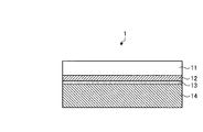
- FIG. 1 is a schematic cross-sectional view showing an example of the resin sheet of the present invention.
- FIG. 2 is a schematic view showing an example of a method for producing a resin sheet of the present invention.
- FIG. 3 is a schematic view showing another example of the method for producing a resin sheet of the present invention.
- the resin sheet of the present invention comprises a support, a first resin composition layer comprising the first resin composition provided on the support, and a second resin provided on the first resin composition layer.
- a second resin composition layer made of a resin composition, and the first resin composition and the second resin composition between the first resin composition layer and the second resin composition layer.
- a thickness of the mixed layer is 0.4 ⁇ m or more.
- an insulating layer formed using a resin sheet including a plurality of resin composition layers delamination may occur when exposed to a high temperature environment such as during reflow.
- the present inventors have found that.
- a plurality of cured product layers derived from each resin composition layer are formed in the obtained insulating layer.
- These cured product layers may exhibit different expansion rates under a high temperature environment due to the difference in composition. In such a case, since stress concentrates between the layers, it is assumed that delamination is likely to occur.
- the resin sheet of the present invention has a mixed layer in which the respective resin compositions forming the first and second resin composition layers are mixed between the first and second resin composition layers.
- the first cured product layer derived from the first resin composition layer and the second cured product derived from the second resin composition layer A cured product layer derived from the mixed layer is formed between the layers.
- the cured product layer derived from the mixed layer relieves stress concentration caused by the difference in expansion coefficient between the first cured product layer and the second cured product layer, and therefore delamination in a high-temperature environment such as during reflow. Can be suppressed.
- a stress relaxation layer may be formed depending on the composition of each resin composition layer and thermosetting conditions.
- the thickness of the formed stress relaxation layer is not sufficient to solve the problem of delamination in a high temperature environment.
- the resin sheet of the present invention having a mixed layer of a predetermined thickness, an insulating layer in which delamination is suppressed can be easily performed regardless of the composition of each resin composition layer and thermosetting conditions. It is feasible.
- FIG. 1 is a schematic cross-sectional view showing an example of the resin sheet of the present invention.
- the support body 11, the 1st resin composition layer 12, the mixed layer 13, and the 2nd resin composition layer 14 are laminated
- each layer which comprises the resin sheet of this invention is demonstrated in detail.
- the resin sheet of the present invention has a support.
- the support in the present invention include a film made of a plastic material, a metal foil, and a release paper, and a film made of a plastic material and a metal foil are preferable.
- plastic material examples include polyethylene terephthalate (hereinafter sometimes abbreviated as “PET”) and polyethylene naphthalate (hereinafter abbreviated as “PEN”).
- PET polyethylene terephthalate
- PEN polyethylene naphthalate
- Polyester polycarbonate (hereinafter sometimes abbreviated as “PC”), polymethyl methacrylate (PMMA) and other acrylics, cyclic polyolefin, triacetyl cellulose (TAC), polyether sulfide (PES), polyether Examples include ketones and polyimides.
- PC polycarbonate
- PMMA polymethyl methacrylate
- TAC triacetyl cellulose
- PES polyether sulfide
- ketones and polyimides examples include ketones and polyimides.
- polyethylene terephthalate and polyethylene naphthalate are preferable, and inexpensive polyethylene terephthalate is particularly preferable.
- examples of the metal foil include a copper foil and an aluminum foil, and a copper foil is preferable.
- a foil made of a single metal of copper may be used, and a foil made of an alloy of copper and another metal (for example, tin, chromium, silver, magnesium, nickel, zirconium, silicon, titanium, etc.). It may be used.
- the support may be subjected to mat treatment or corona treatment on the surface to be bonded to the first resin composition layer.
- a support with a release layer having a release layer on the surface to be bonded to the first resin composition layer may be used.
- the release agent used for the release layer of the support with a release layer include one or more release agents selected from the group consisting of alkyd resins, polyolefin resins, urethane resins, and silicone resins.
- a commercially available product may be used.
- “SK-1” manufactured by Lintec Corporation which is a PET film having a release layer mainly composed of an alkyd resin release agent.
- AL-5”, “AL-7”, “Lumirror T6AM” manufactured by Toray Industries, Inc., and the like are examples of the release agent used for the release layer of the support with a release layer.
- the thickness of the support is not particularly limited, but is preferably in the range of 5 ⁇ m to 75 ⁇ m, and more preferably in the range of 10 ⁇ m to 60 ⁇ m.
- the thickness of the whole support body with a release layer is the said range.
- the resin sheet of the present invention has a first resin composition layer made of the first resin composition.
- the first resin composition layer is bonded to the support, and when the printed wiring board is manufactured, a region in the vicinity of the surface of the insulating layer on which the conductor layer is provided is formed.
- the first resin composition is not particularly limited as long as the cured product has sufficient hardness and insulation.
- curing agent is mentioned, for example.
- curable resin the conventionally well-known curable resin used when forming the insulating layer of a printed wiring board can be used, and an epoxy resin is especially preferable.
- the first resin composition includes (a) an epoxy resin and (b) a curing agent. If necessary, the first resin composition may further contain (c) an inorganic filler, (d) a thermoplastic resin, (e) a curing accelerator, (f) a flame retardant, and (g) an organic filler. An agent may be included.
- Epoxy resin- examples include bisphenol A type epoxy resin, bisphenol F type epoxy resin, bisphenol S type epoxy resin, bisphenol AF type epoxy resin, dicyclopentadiene type epoxy resin, trisphenol type epoxy resin, naphthol novolak type epoxy resin, Phenol novolac type epoxy resin, tert-butyl-catechol type epoxy resin, naphthalene type epoxy resin, naphthol type epoxy resin, anthracene type epoxy resin, glycidyl amine type epoxy resin, glycidyl ester type epoxy resin, cresol novolac type epoxy resin, biphenyl type Epoxy resin, linear aliphatic epoxy resin, epoxy resin having butadiene structure, alicyclic epoxy resin, heterocyclic epoxy resin, spiro ring-containing ester Carboxymethyl resins, cyclohexanedimethanol type epoxy resins, naphthylene ether type epoxy resins and trimethylol type epoxy resins.
- An epoxy resin may be
- the epoxy resin preferably contains an epoxy resin having two or more epoxy groups in one molecule.
- the nonvolatile component of the epoxy resin is 100% by mass, at least 50% by mass or more is preferably an epoxy resin having two or more epoxy groups in one molecule.
- the epoxy resin may also contain an epoxy resin having two or more epoxy groups in one molecule and liquid at 20 ° C. (hereinafter referred to as “liquid epoxy resin”).
- the content of the solid epoxy resin in the epoxy resin is preferably 30% by mass or more, more preferably 40% by mass or more, when the nonvolatile component of the entire epoxy resin is 100% by mass. More preferably, they are 50 mass% or more, 60 mass% or more, 70 mass% or more, 80 mass% or more, or 90 mass% or more.
- the upper limit of the content of the solid epoxy resin is not particularly limited, and may be 100% by mass.
- Liquid epoxy resins include bisphenol A type epoxy resin, bisphenol F type epoxy resin, bisphenol AF type epoxy resin, glycidyl ester type epoxy resin, glycidyl amine type epoxy resin, cycloaliphatic epoxy resin having ester skeleton, cyclohexanedimethanol type Epoxy resin, glycidylamine type epoxy resin, epoxy resin having butadiene structure, phenol novolac type epoxy resin, and naphthalene type epoxy resin are preferable, bisphenol A type epoxy resin, bisphenol F type epoxy resin, bisphenol AF type epoxy resin, and naphthalene Type epoxy resin is more preferable, and bisphenol A type epoxy resin, bisphenol F type epoxy resin, and bisphenol AF type epoxy resin are more preferable.
- liquid epoxy resin examples include “HP4032”, “HP4032D”, “HP4032SS” (naphthalene type epoxy resin) manufactured by DIC Corporation, and “jER828EL” (bisphenol A type epoxy resin) manufactured by Mitsubishi Chemical Corporation.
- JER807 bisphenol F type epoxy resin
- YL7223 bisphenol AF type epoxy resin
- jER152 phenol novolac type epoxy resin
- ZX1059 manufactured by Nippon Steel & Sumikin Chemical Co., Ltd.
- Bisphenol A type epoxy resin and bisphenol F type epoxy resin examples of the liquid epoxy resin
- EX-721 examples of the liquid epoxy resin
- Solid epoxy resins include naphthalene type tetrafunctional epoxy resin, cresol novolac type epoxy resin, dicyclopentadiene type epoxy resin, trisphenol type epoxy resin, naphthol type epoxy resin, biphenyl type epoxy resin, naphthol novolak type epoxy resin, biphenyl.
- Type epoxy resin, naphthylene ether type epoxy resin, anthracene type epoxy resin, bisphenol A type epoxy resin, and tetraphenylethane type epoxy resin are preferable, naphthalene type tetrafunctional epoxy resin, biphenyl type epoxy resin, or naphthylene ether type epoxy Resins are more preferable, and naphthalene type tetrafunctional epoxy resins and biphenyl type epoxy resins are more preferable.
- solid epoxy resin examples include “HP-4700”, “HP-4710” (naphthalene type tetrafunctional epoxy resin), “N-690” (cresol novolac type epoxy resin) manufactured by DIC Corporation, “ N-695 ”(cresol novolac type epoxy resin),“ HP-7200 ”(dicyclopentadiene type epoxy resin),“ EXA7311 ”,“ EXA7311-G3 ”,“ EXA7311-G4 ”,“ EXA7311-G4S ”,“ HP6000 ” ”(Naphthylene ether type epoxy resin),“ EPPN-502H ”(trisphenol epoxy resin) manufactured by Nippon Kayaku Co., Ltd.,“ NC7000L ”(naphthol novolac epoxy resin),“ NC3000H ”,“ NC3000 ”,“ NC3000L ” ”,“ NC3100 ”(biphenyl type XES resin), “ESN475V” (naphthol no
- the content of the epoxy resin in the first resin composition is preferably 5% by mass or more, more preferably 10% by mass or more, and further preferably 20% by mass or more or 30% by mass or more.
- the upper limit of content of an epoxy resin is not specifically limited, Preferably it is 50 mass% or less, More preferably, it is 45 mass% or less, More preferably, it is 40 mass% or less.
- content of each component which comprises a resin composition is a value when the sum total of the non-volatile component in a resin composition is 100 mass% unless there is separate description.
- the epoxy equivalent of the epoxy resin is preferably 50 to 3000, more preferably 80 to 2000, and still more preferably 110 to 1000. By becoming this range, the crosslinked density of hardened
- the epoxy equivalent can be measured according to JIS K7236, and is the mass of a resin containing 1 equivalent of an epoxy group.
- the weight average molecular weight of the epoxy resin is preferably 100 to 5000, more preferably 250 to 3000, and still more preferably 400 to 1500.
- the weight average molecular weight of the epoxy resin is a weight average molecular weight in terms of polystyrene measured by a gel permeation chromatography (GPC) method.
- the curing agent is not particularly limited as long as it has a function of curing the epoxy resin.
- a phenolic curing agent, a naphthol curing agent, an active ester curing agent, a benzoxazine curing agent, a cyanate ester curing agent, and Examples thereof include carbodiimide curing agents.
- curing agent may be used individually by 1 type, or may use 2 or more types together.
- a phenol-based curing agent having a novolak structure or a naphthol-based curing agent having a novolak structure is preferable from the viewpoint of heat resistance and water resistance.
- curing agent is preferable and a triazine frame
- curing agent is more preferable.
- a triazine skeleton-containing phenol novolac curing agent is preferable from the viewpoint of highly satisfying heat resistance, water resistance, and adhesion to the conductor layer (peel strength).
- phenol-based curing agent and the naphthol-based curing agent include, for example, “MEH-7700”, “MEH-7810”, “MEH-7785” manufactured by Meiwa Kasei Co., Ltd., and Nippon Kayaku Co., Ltd. “NHN”, “CBN”, “GPH”, “SN170”, “SN180”, “SN190”, “SN475”, “SN485”, “SN495”, “SN375”, “SN395” manufactured by Nippon Steel & Sumikin Co., Ltd. And “LA-7052,” “LA-7054,” “LA-3018,” “EXB-9500” manufactured by DIC Corporation.
- triazine skeleton-containing phenol novolak curing agent include “LA-3018-50P” and the like.
- an active ester curing agent is also preferable.
- the active ester curing agent is not particularly limited, but generally one molecule of ester group having high reaction activity, such as phenol esters, thiophenol esters, N-hydroxyamine esters, and heterocyclic hydroxy compound esters. A compound having two or more thereof is preferably used.
- the active ester curing agent is preferably obtained by a condensation reaction between a carboxylic acid compound and / or a thiocarboxylic acid compound and a hydroxy compound and / or a thiol compound.
- an active ester curing agent obtained from a carboxylic acid compound and a hydroxy compound is preferable, and an active ester curing agent obtained from a carboxylic acid compound and a phenol compound and / or a naphthol compound is more preferable.
- the carboxylic acid compound include benzoic acid, acetic acid, succinic acid, maleic acid, itaconic acid, phthalic acid, isophthalic acid, terephthalic acid, and pyromellitic acid.
- phenol compound or naphthol compound examples include hydroquinone, resorcin, bisphenol A, bisphenol F, bisphenol S, phenolphthaline, methylated bisphenol A, methylated bisphenol F, methylated bisphenol S, phenol, o-cresol, m- Cresol, p-cresol, catechol, ⁇ -naphthol, ⁇ -naphthol, 1,5-dihydroxynaphthalene, 1,6-dihydroxynaphthalene, 2,6-dihydroxynaphthalene, dihydroxybenzophenone, trihydroxybenzophenone, tetrahydroxybenzophenone, phloroglucin, Benzenetriol, dicyclopentadiene type diphenol compound, phenol novolac and the like can be mentioned.
- the “dicyclopentadiene type diphenol compound” refers to a diphenol compound obtained by condensing two molecules of phenol with one molecule of dicyclopentadiene.
- an active ester compound containing a dicyclopentadiene-type diphenol structure an active ester compound containing a naphthalene structure, an active ester compound containing an acetylated product of a phenol novolac, and an active ester compound containing a benzoylated product of a phenol novolac are preferred, Of these, active ester compounds having a naphthalene structure and active ester compounds having a dicyclopentadiene type diphenol structure are more preferred.
- the “dicyclopentadiene type diphenol structure” represents a divalent structural unit composed of phenylene-dicyclopentylene-phenylene.
- active ester curing agents include “EXB9451”, “EXB9460”, “EXB9460S”, “HPC-8000-65T” (made by DIC Corporation) as active ester compounds containing a dicyclopentadiene type diphenol structure. ), “EXB9416-70BK” (manufactured by DIC Corporation) as an active ester compound containing a naphthalene structure, “DC808” (manufactured by Mitsubishi Chemical Corporation) as an active ester compound containing an acetylated product of phenol novolac, and benzoyl of phenol novolac Examples of the active ester compound containing a compound include “YLH1026” (manufactured by Mitsubishi Chemical Corporation).
- benzoxazine-based curing agent examples include “HFB2006M” manufactured by Showa Polymer Co., Ltd. and “Pd” and “Fa” manufactured by Shikoku Kasei Kogyo Co., Ltd.
- cyanate ester curing agent examples include bisphenol A dicyanate, polyphenol cyanate, oligo (3-methylene-1,5-phenylene cyanate), 4,4′-methylenebis (2,6-dimethylphenyl cyanate), 4,4 '-Ethylidene diphenyl dicyanate, hexafluorobisphenol A dicyanate, 2,2-bis (4-cyanate) phenylpropane, 1,1-bis (4-cyanatephenylmethane), bis (4-cyanate-3,5-dimethyl) Bifunctional cyanate resins such as phenyl) methane, 1,3-bis (4-cyanatephenyl-1- (methylethylidene)) benzene, bis (4-cyanatephenyl) thioether, and bis (4-cyanatephenyl) ether, phenol Novolac and Polyfunctional cyanate resin derived from resol novolac, these cyanate resins and partially triazine of prepolymer.
- cyanate ester curing agent examples include “PT30” and “PT60” (both phenol novolak polyfunctional cyanate ester resins) and “BA230” (part or all of bisphenol A dicyanate) manufactured by Lonza Japan Co., Ltd. And the like, and the like, and the like.
- carbodiimide curing agent examples include “V-03” and “V-07” manufactured by Nisshinbo Chemical Co., Ltd.
- the amount ratio of the epoxy resin and the curing agent is preferably a ratio of [total number of epoxy groups of the epoxy resin]: [total number of reactive groups of the curing agent] in the range of 1: 0.2 to 1: 2.
- the ratio is more preferably 1: 0.3 to 1: 1.5, and further preferably 1: 0.4 to 1: 1.2.
- the reactive group of the curing agent is an active hydroxyl group, an active ester group or the like, and varies depending on the type of the curing agent.
- the total number of epoxy groups of the epoxy resin is a value obtained by dividing the value obtained by dividing the solid mass of each epoxy resin by the epoxy equivalent for all epoxy resins
- the total number of reactive groups of the curing agent is:
- the value obtained by dividing the solid mass of each curing agent by the reactive group equivalent is the total value for all curing agents.
- the first resin composition includes the above-described (a) epoxy resin and (b) a curing agent.
- the first resin composition is (a) an epoxy resin containing a solid epoxy resin as an epoxy resin (the content of the solid epoxy resin in the epoxy resin is preferably 30% by mass or more, more preferably 40% by mass or more, More preferably 50% by mass or more, 60% by mass or more, 70% by mass or more, 80% by mass or more, or 90% by mass or more) (b) a phenol-based curing agent, a naphthol-based curing agent, an active ester type as a curing agent
- One or more selected from the group consisting of curing agents and cyanate ester curing agents preferably one or more selected from the group consisting of phenolic curing agents, naphthol curing agents and active ester curing agents
- the content of the curing agent in the first resin composition is not particularly limited, but is preferably 30% by mass or less, more preferably 25% by mass or less, still more preferably 20% by mass or less, and even more preferably 15% by mass or less. It is.
- the lower limit is not particularly limited but is preferably 3% by mass or more.
- the first resin composition may further contain an inorganic filler.
- the material of the inorganic filler is not particularly limited. For example, silica, alumina, glass, cordierite, silicon oxide, barium sulfate, barium carbonate, talc, clay, mica powder, zinc oxide, hydrotalcite, boehmite, water Aluminum oxide, magnesium hydroxide, calcium carbonate, magnesium carbonate, magnesium oxide, boron nitride, aluminum nitride, manganese nitride, aluminum borate, strontium carbonate, strontium titanate, calcium titanate, magnesium titanate, bismuth titanate, titanium oxide , Zirconium oxide, barium titanate, barium zirconate titanate, barium zirconate, calcium zirconate, zirconium phosphate, and zirconium tungstate phosphate.
- silica such as amorphous silica, fused silica, crystalline silica, synthetic silica, and hollow silica is particularly suitable. Moreover, spherical silica is preferable as the silica.
- An inorganic filler may be used individually by 1 type, and may be used in combination of 2 or more type.
- the average particle diameter of the inorganic filler used in the first resin composition is not particularly limited, but is preferably 600 nm or less, more preferably 300 nm or less, and even more preferably 200 nm, from the viewpoint of obtaining an insulating layer having a small surface roughness.
- it is 150 nm or less, 100 nm or less, 90 nm or less, 80 nm or less, 70 nm or less, 60 nm or less, or 50 nm or less.
- the minimum of this average particle diameter is not specifically limited, Usually, it is 5 nm or more.
- Examples of commercially available inorganic fillers having such an average particle diameter include “YC100C”, “YA050C”, “YA050C-MJE”, “YA010C” manufactured by Admatechs Co., Ltd., “UFP-” manufactured by Denki Kagaku Kogyo. 30 ”,“ Sylfil NSS-3N ”,“ Silfil NSS-4N ”, and“ Sylfil NSS-5N ”manufactured by Tokuyama.
- the average particle diameter of the inorganic filler can be measured by a laser diffraction / scattering method based on Mie scattering theory.
- the particle size distribution of the inorganic filler can be prepared on a volume basis by a laser diffraction / scattering particle size distribution measuring apparatus, and the median diameter can be measured as the average particle diameter.
- a laser diffraction / scattering particle size distribution measuring apparatus “LA-500” manufactured by Horiba, Ltd. or the like can be used.
- Inorganic fillers are aminosilane coupling agents, epoxysilane coupling agents, mercaptosilane coupling agents, silane coupling agents, organosilazane compounds, titanate coupling agents from the viewpoint of improving moisture resistance and dispersibility. It is preferable that it is processed with 1 or more types of surface treating agents. Examples of commercially available surface treatment agents include “KBM403” (3-glycidoxypropyltrimethoxysilane) manufactured by Shin-Etsu Chemical Co., Ltd. and “KBM803” (3-mercaptopropyltrimethoxysilane) manufactured by Shin-Etsu Chemical Co., Ltd.
- the degree of surface treatment with the surface treatment agent can be evaluated by the amount of carbon per unit surface area of the inorganic filler.
- Carbon content per unit surface area of the inorganic filler from the viewpoint of improving dispersibility of the inorganic filler is preferably 0.02 mg / m 2 or more, 0.1 mg / m 2 or more preferably, 0.2 mg / m 2 The above is more preferable.
- 1 mg / m 2 or less is preferable, 0.8 mg / m 2 or less is more preferable, and 0.5 mg / m 2 or less is more preferable from the viewpoint of preventing an increase in the melt viscosity of the resin varnish or the sheet form. preferable.
- the amount of carbon per unit surface area of the inorganic filler can be measured after the surface-treated inorganic filler is washed with a solvent (for example, methyl ethyl ketone (MEK)). Specifically, a sufficient amount of MEK as a solvent is added to the inorganic filler surface-treated with the surface treatment agent and ultrasonically cleaned at 25 ° C. for 5 minutes. After removing the supernatant and drying the solid, the carbon amount per unit surface area of the inorganic filler can be measured using a carbon analyzer. As the carbon analyzer, “EMIA-320V” manufactured by Horiba, Ltd. can be used.
- EMIA-320V manufactured by Horiba, Ltd.
- the content of the inorganic filler in the first resin composition is not particularly limited, but is preferably 60% by mass or less, more preferably 55% by mass or less, still more preferably 50% by mass or less, and even more preferably 48% by mass. Hereinafter, it is 46 mass% or less, 44 mass% or less, 42 mass% or less, or 40 mass% or less.
- the lower limit of the content of the inorganic filler in the first resin composition is not particularly limited, and may be 0% by mass.
- the first resin composition may further contain a thermoplastic resin.
- the thermoplastic resin include phenoxy resin, polyvinyl acetal resin, acrylic resin, polyolefin resin, polybutadiene resin, polyimide resin, polyamideimide resin, polyethersulfone resin, polyetherimide resin, polycarbonate resin, polyetheretherketone resin, Examples include polyester resins, polyphenylene ether resins, and polysulfone resins.
- a thermoplastic resin may be used individually by 1 type, or may use 2 or more types together.
- the weight average molecular weight in terms of polystyrene of the thermoplastic resin is preferably in the range of 8,000 to 70,000, more preferably in the range of 10,000 to 60,000, and still more preferably in the range of 20,000 to 60,000.
- the weight average molecular weight in terms of polystyrene of the thermoplastic resin is measured by a gel permeation chromatography (GPC) method.
- GPC gel permeation chromatography
- the polystyrene-converted weight average molecular weight of the thermoplastic resin is LC-9A / RID-6A manufactured by Shimadzu Corporation as a measuring device, and Shodex K-800P / K- manufactured by Showa Denko KK as a column. 804L / K-804L can be measured using chloroform or the like as a mobile phase at a column temperature of 40 ° C. and calculated using a standard polystyrene calibration curve.
- phenoxy resin examples include bisphenol A skeleton, bisphenol F skeleton, bisphenol S skeleton, bisphenolacetophenone skeleton, novolac skeleton, biphenyl skeleton, fluorene skeleton, dicyclopentadiene skeleton, norbornene skeleton, naphthalene skeleton, anthracene skeleton, adamantane skeleton, terpene
- the terminal of the phenoxy resin may be any functional group such as a phenolic hydroxyl group or an epoxy group.
- a phenoxy resin may be used individually by 1 type, or may use 2 or more types together.
- Specific examples of the phenoxy resin include “1256” and “4250” (both bisphenol A skeleton-containing phenoxy resin), “YX8100” (bisphenol S skeleton-containing phenoxy resin), and “YX6954” (manufactured by Mitsubishi Chemical Corporation).
- “FX280” and “FX293” manufactured by Nippon Steel & Sumikin Chemical Co., Ltd., “YX7553BH30”, “YL7769BH30”, “YL6794” manufactured by Mitsubishi Chemical Corporation, "YL7213", “YL7290”, “YL7482”, etc. are mentioned.
- the acrylic resin is preferably a functional group-containing acrylic resin, more preferably an epoxy group-containing acrylic resin, and still more preferably an epoxy group-containing acrylic ester copolymer resin.
- the functional group equivalent is preferably 1000 to 50000, more preferably 2500 to 30000.
- acrylic resin examples include “SG-80H” and “SG-P3” (epoxy group-containing acrylic ester copolymer resin) manufactured by Nagase ChemteX Corporation.
- polyvinyl acetal resin examples include polyvinyl formal resin and polyvinyl butyral resin, and polyvinyl butyral resin is preferable.
- Specific examples of the polyvinyl acetal resin include electrified butyral 4000-2, 5000-A, 6000-C, and 6000-EP manufactured by Denki Kagaku Kogyo Co., Ltd., and the ESREC BH series and BX series manufactured by Sekisui Chemical Co., Ltd.
- Examples include the KS series (specifically “KS-1”, etc.), the BL series, the BM series, and the like.
- polyimide resins include “Rika Coat SN20” and “Rika Coat PN20” manufactured by Shin Nippon Rika Co., Ltd.
- Specific examples of the polyimide resin include linear polyimide obtained by reacting a bifunctional hydroxyl group-terminated polybutadiene, a diisocyanate compound and a tetrabasic acid anhydride (Japanese Patent Laid-Open No. 2006-37083), a polysiloxane skeleton-containing polyimide. Examples thereof include modified polyimides such as JP-A Nos. 2002-12667 and 2000-319386.
- polyamide-imide resin examples include “Bilomax HR11NN” and “Bilomax HR16NN” manufactured by Toyobo Co., Ltd.
- polyamideimide resin also include modified polyamideimides such as polysiloxane skeleton-containing polyamideimides “KS9100” and “KS9300” manufactured by Hitachi Chemical Co., Ltd.
- polyethersulfone resin examples include “PES5003P” manufactured by Sumitomo Chemical Co., Ltd.
- polysulfone resin examples include polysulfone “P1700” and “P3500” manufactured by Solvay Advanced Polymers Co., Ltd.
- the content of the thermoplastic resin in the first resin composition is not particularly limited, but is preferably 0.1% by mass or more, more preferably 1% by mass or more, further preferably 3% by mass or more, 5% by mass or more or 7% by mass or more.
- the upper limit of content of a thermoplastic resin is not specifically limited, Preferably it is 30 mass% or less, More preferably, it is 20 mass% or less, More preferably, it is 10 mass% or less.
- the first resin composition may further contain a curing accelerator.
- the curing accelerator include a phosphorus-based curing accelerator, an amine-based curing accelerator, an imidazole-based curing accelerator, a guanidine-based curing accelerator, a metal-based curing accelerator, and the like.
- a curing accelerator and an imidazole curing accelerator are preferable, and an amine curing accelerator and an imidazole curing accelerator are more preferable.
- a hardening accelerator may be used individually by 1 type, and may be used in combination of 2 or more type.
- Examples of phosphorus curing accelerators include triphenylphosphine, phosphonium borate compounds, tetraphenylphosphonium tetraphenylborate, n-butylphosphonium tetraphenylborate, tetrabutylphosphonium decanoate, and (4-methylphenyl) triphenylphosphonium thiocyanate.
- Tetraphenylphosphonium thiocyanate, butyltriphenylphosphonium thiocyanate and the like, and triphenylphosphine and tetrabutylphosphonium decanoate are preferable.
- amine curing accelerators examples include trialkylamines such as triethylamine and tributylamine, 4-dimethylaminopyridine, benzyldimethylamine, 2,4,6, -tris (dimethylaminomethyl) phenol, 1,8-diazabicyclo. (5,4,0) -undecene and the like, and 4-dimethylaminopyridine and 1,8-diazabicyclo (5,4,0) -undecene are preferable.
- trialkylamines such as triethylamine and tributylamine
- 4-dimethylaminopyridine such as triethylamine and tributylamine
- benzyldimethylamine 2,4,6, -tris (dimethylaminomethyl) phenol
- 1,8-diazabicyclo. (5,4,0) -undecene 1,8-diazabicyclo
- imidazole curing accelerator examples include 2-methylimidazole, 2-undecylimidazole, 2-heptadecylimidazole, 1,2-dimethylimidazole, 2-ethyl-4-methylimidazole, 1,2-dimethylimidazole, 2-ethyl-4-methylimidazole, 2-phenylimidazole, 2-phenyl-4-methylimidazole, 1-benzyl-2-methylimidazole, 1-benzyl-2-phenylimidazole, 1-cyanoethyl-2-methylimidazole, 1-cyanoethyl-2-undecylimidazole, 1-cyanoethyl-2-ethyl-4-methylimidazole, 1-cyanoethyl-2-phenylimidazole, 1-cyanoethyl-2-undecylimidazolium trimellitate, 1-cyanoethyl- 2 Phenylimidazolium trimellitate, 2,4-
- guanidine curing accelerator examples include dicyandiamide, 1-methylguanidine, 1-ethylguanidine, 1-cyclohexylguanidine, 1-phenylguanidine, 1- (o-tolyl) guanidine, dimethylguanidine, diphenylguanidine, trimethylguanidine, Tetramethylguanidine, pentamethylguanidine, 1,5,7-triazabicyclo [4.4.0] dec-5-ene, 7-methyl-1,5,7-triazabicyclo [4.4.0] Deca-5-ene, 1-methyl biguanide, 1-ethyl biguanide, 1-n-butyl biguanide, 1-n-octadecyl biguanide, 1,1-dimethyl biguanide, 1,1-diethyl biguanide, 1-cyclohexyl biguanide, 1 -Allyl biguanide, 1-phenyl biguanide, 1- ( - tolyl) biguanide
- the organometallic complex or organometallic salt of metals such as cobalt, copper, zinc, iron, nickel, manganese, tin
- the organometallic complex include organic cobalt complexes such as cobalt (II) acetylacetonate and cobalt (III) acetylacetonate, organic copper complexes such as copper (II) acetylacetonate, and zinc (II) acetylacetonate.
- Organic zinc complexes such as iron (III) acetylacetonate, organic nickel complexes such as nickel (II) acetylacetonate, and organic manganese complexes such as manganese (II) acetylacetonate.
- organic metal salt include zinc octylate, tin octylate, zinc naphthenate, cobalt naphthenate, tin stearate, and zinc stearate.
- the content of the curing accelerator in the first resin composition is not particularly limited, but in the range of 0.05% by mass to 3% by mass when the total amount of the nonvolatile components of the epoxy resin and the curing agent is 100% by mass. It is preferable to use it.
- the first resin composition may further contain a flame retardant.
- the flame retardant include an organic phosphorus flame retardant, an organic nitrogen-containing phosphorus compound, a nitrogen compound, a silicone flame retardant, and a metal hydroxide.
- a flame retardant may be used individually by 1 type, or may use 2 or more types together.
- Commercially available products may be used as the flame retardant, and examples thereof include “HCA-HQ” manufactured by Sanko Co., Ltd.
- the content of the flame retardant in the first resin composition layer is not particularly limited, but is preferably 0.5% by mass to 20% by mass, more preferably 1% by mass to 15% by mass, and still more preferably 1.5% by mass. % To 10% by mass is more preferable.
- the first resin composition may further contain an organic filler.
- an organic filler any organic filler that can be used for forming an insulating layer of a printed wiring board may be used. Examples thereof include rubber particles, polyamide fine particles, and silicone particles, and rubber particles are preferable. A commercially available product may be used as the rubber particles, and examples thereof include “AC3816N” manufactured by Aika Industry Co., Ltd.
- the content of the organic filler in the first resin composition is preferably 1% by mass to 20% by mass, more preferably 2% by mass to 10% by mass.
- the first resin composition may contain other additives as necessary.
- other additives include organic metals such as organic copper compounds, organic zinc compounds, and organic cobalt compounds.
- examples include compounds and resin additives such as organic fillers, thickeners, antifoaming agents, leveling agents, adhesion-imparting agents, and coloring agents.
- the thickness of the first resin composition layer is preferably 0.3 ⁇ m to 15 ⁇ m from the viewpoint of obtaining an insulating layer having high stability of roughness and peel strength.
- the lower limit of the thickness of the first resin composition layer is more preferably 0.5 ⁇ m or more, further preferably 1 ⁇ m or more, 1.5 ⁇ m or more, 2 ⁇ m or more, 2.5 ⁇ m or more, or 3 ⁇ m or more. In particular, when the thickness of the first resin composition layer is 1 ⁇ m or more, the stability of roughness and peel strength can be further improved.
- the upper limit of the thickness of the first resin composition layer is more preferably 12 ⁇ m or less, still more preferably 10 ⁇ m or less, 9 ⁇ m or less, or 8 ⁇ m or less. In addition, it is preferable that the thickness of the 1st resin composition layer is thinner than the thickness of the 2nd resin composition layer.
- the thickness of the first resin composition layer can be measured according to the procedure described later (measurement of the thickness of each layer of the resin sheet
- the minimum melt viscosity of the first resin composition layer is 3000 poise from the viewpoint that it is easy to maintain the desired thickness when laminated on the inner layer substrate, and that an insulating layer having high stability of roughness and peel strength can be achieved. (300 Pa ⁇ s) or more is preferable, 5000 poise (500 Pa ⁇ s) or more is more preferable, and 10,000 poise (1000 Pa ⁇ s) or more is more preferable. In particular, when the minimum melt viscosity is 5000 poise or more, an insulating layer exhibiting particularly good reflow resistance can be obtained.
- the upper limit of the minimum melt viscosity of the first resin composition layer is not particularly limited, but is preferably 100000 poise (10000 Pa ⁇ s) or less, more preferably 80000 poise (8000 Pa ⁇ s) or less, and 50000 poise (5000 Pa ⁇ s) or less. Further preferred.
- the minimum melt viscosity of the first resin composition layer refers to the minimum viscosity exhibited by the resin composition layer when the resin of the first resin composition layer is melted. Specifically, when the first resin composition layer is heated at a constant rate of temperature to melt the resin, the initial stage of the melt viscosity decreases as the temperature rises, and then melts as the temperature increases beyond a certain level. Viscosity increases.
- the minimum melt viscosity refers to the melt viscosity at such a minimum point.
- the minimum melt viscosity of the first resin composition layer is, for example, a dynamic viscoelasticity measuring apparatus (“Rheosol-G3000” manufactured by UBM Co., Ltd.). The temperature is increased from a starting temperature of 60 ° C.
- the definition and measurement method of the minimum melt viscosity of the second resin composition layer are the same.
- the resin sheet of the present invention has a second resin composition layer made of the second resin composition.
- the second resin composition layer affects the bulk properties of the resulting insulating layer.
- the second resin composition contains an inorganic filler. It is preferable.
- the content of the inorganic filler in the second resin composition is preferably 50% by mass or more, more preferably 55% by mass or more, and further preferably 60% by mass from the viewpoint of reducing the thermal expansion coefficient of the obtained insulating layer. % Or more, 62 mass% or more, 64 mass% or more, 66 mass% or more, 68 mass% or more, or 70 mass% or more.
- the upper limit of the content of the inorganic filler in the second resin composition is preferably 96% by mass or less, more preferably 95% by mass or less, and still more preferably 90% by mass from the viewpoint of mechanical strength of the obtained insulating layer. Or 85% by mass or less.
- the content of the inorganic filler in the second resin composition is higher than the content of the inorganic filler in the first resin composition.
- the difference between A1 and A2 is preferably 10% by mass or more, more preferably 15% by mass or more, still more preferably 20% by mass or more, 25% by mass or more, or 30% by mass or more.
- the upper limit of the difference (A2 ⁇ A1) is not particularly limited, but can usually be 90% by mass or less, 80% by mass or less.
- the present inventors have found that when the difference (A2-A1) is increased, delamination tends to occur in the insulating layer when exposed to a high temperature environment such as during reflow.
- an insulating layer formed using the resin sheet of the present invention having a mixed layer can suppress delamination even when the difference (A2-A1) is large. Therefore, in the present invention, the degree of freedom in designing the composition of each layer is high, and the desired function can be advantageously imparted to each layer.
- A1 and A2 are different from each other in this way, it becomes easier to grasp the mixed layer described later.
- the inorganic filler examples include, for example, the inorganic filler described for the first resin composition. Among them, silica is preferable, and spherical silica is more preferable.
- the average particle diameter of the inorganic filler contained in the second resin composition is in the range of 0.01 ⁇ m to 5 ⁇ m from the viewpoint of improving the fluidity of the second resin composition layer and realizing sufficient circuit embedding properties.
- the range of 0.05 ⁇ m to 2 ⁇ m is more preferable, the range of 0.1 ⁇ m to 1 ⁇ m is more preferable, and the range of 0.2 ⁇ m to 0.8 ⁇ m is even more preferable.
- Examples of commercially available inorganic fillers having such an average particle diameter include “SOC4”, “SOC2”, and “SOC1” manufactured by Admatechs Co., Ltd.
- the inorganic filler contained in the second resin composition is preferably treated with a surface treatment agent.
- the kind of surface treating agent and the degree of surface treatment are as described in the section ⁇ First resin composition layer>.
- the second resin composition includes (a) an epoxy resin, (b) a curing agent, and (c) an inorganic filler. Suitable examples of each component are as described in the ⁇ First resin composition layer> column.
- the second resin composition includes (a) a liquid epoxy resin and a solid epoxy resin as an epoxy resin. (The mass ratio of liquid epoxy resin: solid epoxy resin is preferably in the range of 1: 0.1 to 1: 4, more preferably in the range of 1: 0.3 to 1: 3.5, and 1: 0.
- One or more selected from the group consisting of curing agents and cyanate ester curing agents preferably one or more selected from the group consisting of phenolic curing agents, naphthol curing agents and active ester curing agents
- c) As an inorganic filler Preferably contains silica, respectively.
- the content of the (a) epoxy resin in the second resin composition is not particularly limited, but is preferably 3% by mass to 50% by mass, more preferably 5% by mass to 45% by mass, and still more preferably 5% by mass to It is 40% by mass, and more preferably 7% by mass to 35% by mass.
- the amount ratio of (a) epoxy resin and (b) curing agent in the second resin composition may be the same as that described in the section ⁇ First resin composition layer>.
- curing agent in 2nd resin composition is not specifically limited, Preferably it is 30 mass% or less, More preferably, it is 25 mass% or less, More preferably, it is 20 mass% or less, More preferably, it is 15 It is 10 mass% or less.
- the lower limit is not particularly limited but is preferably 3% by mass or more.
- the second resin composition may further contain one or more components selected from the group consisting of (d) a thermoplastic resin, (e) a curing accelerator, (f) a flame retardant, and (g) an organic filler. Good. Suitable examples of these components (d) to (g) are as described in the section ⁇ First resin composition layer>.
- the content of the thermoplastic resin (d) in the second resin composition is not particularly limited, but is preferably 0.1% by mass to 20% by mass, more preferably 0.5% by mass to 10% by mass.
- the content of (e) the curing accelerator in the second resin composition is preferably 0.05% by mass when the total amount of nonvolatile components of (a) the epoxy resin and (b) the curing agent is 100% by mass. To 3% by mass.
- the content of the flame retardant (f) in the second resin composition is not particularly limited, but is preferably 0.5% by mass to 10% by mass, more preferably 1% by mass to 9% by mass, and even more preferably 1%. .5 mass% to 8 mass%.
- the content of the organic filler (g) in the second resin composition is not particularly limited, but is preferably 1% by mass to 10% by mass, more preferably 2% by mass to 5% by mass.
- the second resin composition may contain other additives as necessary.
- other additives include organic metals such as organic copper compounds, organic zinc compounds, and organic cobalt compounds.
- examples include compounds and resin additives such as organic fillers, thickeners, antifoaming agents, leveling agents, adhesion-imparting agents, and coloring agents.
- the thickness of the second resin composition layer is not particularly limited as long as an insulating layer having a desired thickness can be obtained, but is preferably 3 ⁇ m to 200 ⁇ m.
- the lower limit of the thickness of the second resin composition layer is more preferably 5 ⁇ m or more, further preferably 10 ⁇ m or more, or 15 ⁇ m or more.
- the upper limit of the thickness of the second resin composition layer is more preferably 180 ⁇ m or less, still more preferably 160 ⁇ m or less, 150 ⁇ m or less, 140 ⁇ m or less, 120 ⁇ m or less, or 100 ⁇ m or less.
- the thickness of the second resin composition layer can be measured according to the procedure described later (measurement of the thickness of each layer of the resin sheet).
- the minimum melt viscosity of the second resin composition layer is preferably 10,000 poise (1000 Pa ⁇ s) or less, more preferably 8000 poise (800 Pa ⁇ s) or less, and 5000 poise (500 Pa ⁇ s) from the viewpoint of obtaining good circuit embedding properties.
- the following is more preferable.
- the lower limit is not particularly limited, but is preferably 500 poise (50 Pa ⁇ s) or more, more preferably 800 poise (80 Pa ⁇ s) or more, and further preferably 1000 poise (100 Pa ⁇ s) or more.
- the resin sheet of the present invention has a mixed layer in which the first resin composition and the second resin composition are mixed between the first resin composition layer and the second resin composition layer.
- the thickness of the mixed layer is 0.4 ⁇ m or more, preferably 0.5 ⁇ m or more, and more preferably 1.0 ⁇ m or more from the viewpoint of obtaining an insulating layer in which delamination is suppressed in a high temperature environment such as during reflow.
- the thickness of the first resin composition layer is t ( ⁇ m)
- the thickness of the mixed layer is preferably 2 t or less, more preferably 1.5 t or less, further preferably t or less, 0.9 t or less, 0 0.8 t or less, or 0.7 t or less.
- the thickness of the mixed layer is 2 t or less, it is more preferably 10 ⁇ m or less, further preferably 5 ⁇ m or less, and particularly preferably 3 ⁇ m or less.
- the thickness of the mixed layer can be measured according to the procedure described later (measurement of the thickness of each layer of the resin sheet).
- a mixed layer can be grasped
- the cross section of the resin sheet In SEM observation, the mixed layer can be grasped as follows. That is, in the cross section of the resin sheet, the ratio of the inorganic filler / resin component is constant in the region where the distance from the bonding interface with the support is from 0 to t1, and the distance from the bonding interface with the support is from t1 to t2.
- the inorganic filler / resin component ratio gradually increases, and in the region where the distance from the bonding interface with the support is from t2 to t3, the inorganic filler / resin component ratio is constant.
- the position of the distance t3 from the bonding interface with the support is the surface position of the resin composition layer on the side opposite to the support.
- the region where the distance from the bonding interface with the support is 0 to t1 is the first resin composition layer
- the region where the distance is from t1 to t2 is the mixed layer
- the distance is t2 To t3 is the second resin composition layer.
- the change in the particle size of the inorganic filler It is also possible to grasp the mixed layer from the point of view.
- the resin sheet of the present invention may further include a protective film on the surface of the second resin composition layer.
- the protective film contributes to the prevention of adhesion and scratches of dust and the like on the surface of the second resin composition layer.
- the material for the protective film the same materials as described for the support may be used.
- the thickness of the protective film is not particularly limited, but is, for example, 1 ⁇ m to 40 ⁇ m.
- the resin sheet with a support can be used by peeling off the protective film when producing a printed wiring board.
- the resin sheet of the present invention is used to form an insulating layer of a metal-clad laminate (for an insulating layer of a metal-clad laminate) and to form an insulating layer of a printed wiring board (for an insulating layer of a printed wiring board) can do.
- a metal-clad laminate for an insulating layer of a metal-clad laminate
- a printed wiring board for an insulating layer of a printed wiring board
- it can be suitably used for forming an insulating layer (for build-up insulating layers of printed wiring boards), and for forming a conductor layer by plating (by plating) It can be more suitably used for a build-up insulating layer of a printed wiring board for forming a conductor layer.
- a layer in which the components of each resin composition layer are mixed is provided in a region where the resin composition layers are in contact with each other.
- the present invention realizes an insulating layer in which delamination is suppressed in a high temperature environment.
- a resin sheet including three resin composition layers that is, a first resin composition layer, a second resin composition layer, and an additional resin composition layer (third resin composition layer) can be obtained.
- a mixed layer may be provided between the first resin composition layer and the third resin composition layer and between the second resin composition layer and the third resin composition layer.
- the preferred composition and thickness of the first resin composition layer to be bonded to the support are as described in the above ⁇ First resin composition layer>. is there.
- the preferred composition of the resin composition layer to be bonded to the inner layer substrate is as described in the above ⁇ Second resin composition layer>.
- a resin sheet having the following layer structure can be obtained.
- the composition and thickness of the additional resin composition layer may be appropriately determined according to the design of the desired printed wiring board.
- the insulating layer having an intended function is provided. Can be advantageously achieved without delamination in high temperature environments.
- the resin composition layer containing glass fiber etc. may be sufficient, for example.
- the resin sheet of the present invention is formed on a support, a first resin composition layer made of the first resin composition formed on the support, and a first resin composition layer.
- the first resin varnish in which the first resin composition is dissolved is applied on a support, and the second resin composition is dissolved on the first resin varnish.
- a step of applying and drying the second resin varnish wherein the viscosity of the first resin varnish is 100 mPa ⁇ s or more and the viscosity of the second resin varnish is 100 mPa ⁇ s or more.
- a first resin varnish in which a first resin composition is dissolved is applied onto a support to form a first resin composition layer.
- a second resin varnish in which the second resin composition was dissolved was applied on the first resin composition layer to form a second resin composition layer (hereinafter referred to as “twice coating method”). Also called).
- the first resin varnish and the second resin varnish are applied on the same coating line.
- the second resin varnish is applied not on the first resin composition layer but on the first resin varnish. That is, the second resin varnish is applied before forming the first resin composition layer.
- the method for producing the resin sheet of the present invention is not particularly limited as long as the desired mixed layer can be formed by applying the second resin varnish on the first resin varnish.
- the method for producing the resin sheet of the present invention comprises: The process includes the step of applying the first resin varnish on the support and simultaneously applying the second resin varnish on the first resin varnish and then drying, or applying the first resin varnish on the support Then, after the preliminary drying, the second resin varnish is applied on the first resin varnish and then dried.
- the method including the former step is also referred to as “simultaneous coating method”, and the method including the latter step is also referred to as “tandem coating method”. Note that the simultaneous coating method and the tandem coating method are different from the conventional two-time coating method in that the first resin varnish and the second resin varnish are applied on the same coating line.
- a resin sheet manufacturing apparatus 100 illustrated in FIG. 2 includes a coating apparatus 101 and a drying apparatus 102.
- the support 11 is supplied to the coating apparatus 101.
- the coating device 101 applies the first resin varnish on the support 11 and simultaneously applies the second resin varnish on the first resin varnish.
- the support on which the first and second resin varnishes are applied is supplied to the drying device 102.
- the drying device 102 dries the first and second resin varnishes applied on the support. If necessary, the resin sheet is wound into a roll.
- a first resin composition layer derived from the first resin varnish and a second resin composition layer derived from the second resin varnish are formed on the support, and the first resin composition layer and the first resin composition layer A mixed layer obtained by mixing the first resin varnish and the second resin varnish is formed between the two resin composition layers.
- the simultaneous coating method the thermal history in the production of the resin sheet can be suppressed, and the thermal contraction of the support can be suppressed. Thereby, the resin sheet formed by the simultaneous coating method can provide an insulating layer excellent in stability of roughness and peel strength.
- the simultaneous coating method since the first and second resin varnishes are applied simultaneously, it is easy to form a thick mixed layer. Therefore, the resin sheet manufactured by the simultaneous coating method can provide an insulating layer that is superior in reflow resistance.
- the first and second resin varnishes are applied using a known coating apparatus that can apply the first resin varnish and simultaneously apply the second resin varnish onto the first resin varnish.
- a known coating apparatus that can apply the first resin varnish and simultaneously apply the second resin varnish onto the first resin varnish.
- it can apply
- the first and second resin varnishes can be prepared by dissolving the first and second resin compositions in a solvent, respectively.
- a solvent used for preparation of a resin varnish An organic solvent is preferable.
- the organic solvent include ketones such as acetone, methyl ethyl ketone and cyclohexanone, acetates such as ethyl acetate, butyl acetate, cellosolve acetate, propylene glycol monomethyl ether acetate and carbitol acetate, and carbitols such as cellosolve and butyl carbitol.
- Aromatic hydrocarbons such as toluene and xylene, amide solvents such as dimethylformamide, dimethylacetamide and N-methylpyrrolidone, and solvent naphtha.
- An organic solvent may be used individually by 1 type, or may use 2 or more types together.
- the solvent that dissolves the first resin composition and the solvent that dissolves the second resin composition may be the same or different.
- the solvent contained in the first and second resin varnishes is preferably 75% by mass or less, more preferably 65% by mass or less, further preferably 100% by mass when the total of non-volatile components contained in the resin varnish is 100% by mass. Is adjusted to 55% by mass or less, particularly preferably 45% by mass or less. From the viewpoint of promoting the formation of the mixed layer, the lower limit is preferably 15% by mass or more, and more preferably 20% by mass or more.
- the viscosity of the first resin varnish improves the affinity with the support from the viewpoint that the thickness of the first resin composition layer can be easily controlled, and the first resin varnish can be applied without the occurrence of cissing or streaks.
- it is 100 mPa ⁇ s or more, preferably 200 mPa ⁇ s or more, and more preferably 300 mPa ⁇ s or more.
- the viscosity of the second resin varnish is 100 mPa ⁇ s or more, preferably 200 mPa ⁇ s or more, and more preferably 300 mPa ⁇ s or more.
- 6000 mPa * s or less is preferable from a viewpoint that the thickness of a 2nd resin composition layer is easy to control and thin film formation is easy, and 3000 mPa * s or less is preferable. Is more preferable, and 1000 mPa ⁇ s or less is more preferable.
- the viscosity of the first and second resin varnishes can be measured using, for example, a rotary (E type) viscometer.
- a rotary (E type) viscometer examples include “RE-80U” manufactured by Toki Sangyo Co., Ltd.
- the drying of the first and second resin varnishes may be performed by a known drying method such as heating or hot air blowing.
- the drying conditions are not particularly limited, but the residual solvent amount in the resin sheet after drying is 100% by mass of the total of the non-volatile components contained in the first resin composition layer, the mixed layer, and the second resin composition layer. , It is preferably dried so as to be 10% by mass or less, more preferably 5% by mass or less.
- the lower limit of the residual solvent amount is not particularly limited, but can usually be 0.1% by mass or more, 0.5% by mass or more.
- the temperature is 50 ° C. to 150 ° C.
- the resin sheet of the present invention can be produced by drying for 3 to 10 minutes.
- a resin sheet manufacturing apparatus 200 shown in FIG. 3 includes a first coating apparatus 201, a preliminary drying apparatus 202, a second coating apparatus 203, and a drying apparatus 204.
- the support 11 is supplied to the first coating apparatus 201.
- the first coating apparatus 201 applies a first resin varnish on the support 11.
- the support on which the first resin varnish is applied is supplied to the preliminary drying device 202.
- the predrying device 202 predrys the first resin varnish.
- the support is supplied to the second coating device 203.
- the second coating device 203 applies the second resin varnish onto the first resin varnish.
- the support on which the first and second resin varnishes are applied is supplied to the drying device 204.
- the drying device 204 dries the first and second resin varnishes applied on the support. If necessary, the resin sheet is wound into a roll. As a result, a first resin composition layer derived from the first resin varnish and a second resin composition layer derived from the second resin varnish are formed on the support, and the first resin composition layer and the first resin composition layer A mixed layer obtained by mixing the first resin varnish and the second resin varnish is formed between the two resin composition layers.
- the accuracy of the thickness of the first resin composition layer can be improved.
- the preliminary drying is not particularly limited as long as it does not hinder the formation of the mixed layer by mixing the first resin varnish and the second resin varnish, and is performed by a known drying method such as heating or hot air blowing. May be implemented.
- Preliminary drying conditions are not particularly limited, but the residual solvent amount in the first resin varnish after drying is preferably 70% by mass when the total of the non-volatile components contained in the first resin varnish is 100% by mass.
- it is preliminarily dried so as to be 60% by mass or less, more preferably 50% by mass or less, and particularly preferably 40% by mass or less.
- the lower limit of the residual solvent amount is preferably 15% by mass or more, more preferably 20% by mass or more, and further preferably 25% by mass or more.
- the temperature is from 50 ° C. to 150 ° C. for 0.1 minute to 3%. It is preferable to dry for a minute (more preferably at 60 ° C. to 130 ° C. for 0.2 minute to 2 minutes, more preferably at 70 ° C. to 120 ° C. for 0.3 minute to 1.5 minutes).
- the first and second resin varnishes are as described for the simultaneous coating method. Moreover, you may implement the drying after apply
- the method for producing a resin sheet of the present invention may further include a step of laminating a protective film on the surface of the second resin composition layer (surface opposite to the support side).
- the details of the protective film are as described above.
- a printed wiring board can be manufactured using the resin sheet manufactured by the method of the present invention.
- a printed wiring board can be produced by laminating a resin sheet produced by the method of the present invention on an inner layer substrate and thermally curing it, and then removing the support. Therefore, the printed wiring board of the present invention is characterized by including an insulating layer formed using the resin sheet of the present invention.
- the printed wiring board of the present invention can be produced by a method including the following steps (I) to (III) using the resin sheet of the present invention.
- (I) The step of laminating the resin sheet of the present invention on the inner layer substrate so that the second resin composition layer is joined to the inner layer substrate
- (II) The step of thermosetting the resin sheet to form the insulating layer
- (III) The step of removing the support
- step (I) the resin sheet of the present invention is laminated on the inner layer substrate such that the second resin composition layer is bonded to the inner layer substrate.
- the “inner layer substrate” used in the step (I) is mainly a glass epoxy substrate, a metal substrate, a polyester substrate, a polyimide substrate, a BT resin substrate, a thermosetting polyphenylene ether substrate, or one or both sides of the substrate.
- a circuit board on which a conductor layer (circuit) patterned is formed. Further, when the printed wiring board is manufactured, an inner layer circuit board of an intermediate product in which an insulating layer and / or a conductor layer is further formed is also included in the “inner layer board” in the present invention.
- Lamination of the resin sheet and the inner layer substrate in step (I) may be performed by any conventionally known method, but the second resin composition layer is bonded to the inner layer substrate by roll crimping or press crimping. It is preferable to laminate.
- the laminating process is preferably performed by roll pressing or press pressing. Among these, a vacuum laminating method of laminating under reduced pressure is more preferable.
- the laminating method may be a batch type or a continuous type.
- the bonding temperature It is preferable that the temperature is in the range of ⁇ 120 ° C., the pressure bonding time is in the range of 5 seconds to 180 seconds, and the air pressure is 20 mmHg (26.7 hPa) or less under reduced pressure.
- Lamination can be performed using a commercially available vacuum laminator.
- the commercially available vacuum laminator include a vacuum pressure laminator manufactured by Meiki Seisakusho, a vacuum applicator manufactured by Nichigo Morton, and the like.
- the resin sheet may be laminated on one side of the inner layer substrate or may be laminated on both sides of the inner layer substrate.
- the resin sheet laminated on the inner layer substrate may be subjected to a treatment for smoothing by heating and pressing.
- the smoothing treatment is generally carried out by heating and pressurizing the resin sheet with a heated metal plate or metal roll under normal pressure (atmospheric pressure).
- the heating and pressurizing conditions can be the same conditions as the laminating conditions.
- the laminating process and the smoothing process may be continuously performed using a commercially available vacuum laminator.
- step (II) the resin sheet is thermoset to form an insulating layer.
- the first resin composition layer, the mixed layer, and the second resin composition layer of the laminated resin sheet are thermoset to form an insulating layer.
- thermosetting are not particularly limited, and the conditions normally employed when forming the insulating layer of the printed wiring board may be used.
- the curing temperature is in the range of 120 ° C. to 240 ° C. (preferably 150 ° C. to 210 ° C.
- the curing time can be in the range of 5 minutes to 90 minutes (preferably 10 minutes to 75 minutes, more preferably 15 minutes to 60 minutes).
- each resin composition layer Before the resin sheet is thermally cured, each resin composition layer may be preheated at a temperature lower than the curing temperature. For example, prior to thermosetting the resin sheet, each resin composition layer is heated to 5 ° C. or more and less than 120 ° C. (preferably 60 ° C. or more and 110 ° C. or less, more preferably 70 ° C. or more and 100 ° C. or less) Preheating may be performed for more than a minute (preferably 5 minutes to 150 minutes, more preferably 15 minutes to 120 minutes).
- step (III) the support is removed. Thereby, the surface of the insulating layer is exposed.
- the support may be removed manually or mechanically using an automatic peeling device or the like. Further, when a metal foil is used as the support, it may be removed using a chemical.
- steps (IV) to (VI) may be carried out according to various methods known to those skilled in the art used for the production of printed wiring boards. Note that the support is removed between step (II) and step (IV), between step (IV) and step (V), or between step (V) and step (VI). Good.
- Step (IV) is a step of making a hole in the insulating layer, whereby a hole such as a via hole or a through hole can be formed in the insulating layer.
- a hole can be formed in the insulating layer using a drill, a laser (a carbon dioxide laser, a YAG laser, or the like), plasma, or the like.
- Step (V) is a step of roughening the insulating layer.
- the procedure and conditions for the roughening treatment are not particularly limited, and known procedures and conditions that are usually used when forming an insulating layer of a printed wiring board can be employed.
- the insulating layer can be roughened by performing a swelling treatment with a swelling liquid, a roughening treatment with an oxidizing agent, and a neutralization treatment with a neutralizing liquid in this order.
- a swelling liquid An alkaline solution, surfactant solution, etc. are mentioned, Preferably it is an alkaline solution, As this alkaline solution, a sodium hydroxide solution and a potassium hydroxide solution are more preferable.
- swelling liquids examples include Swelling Dip Securigans P and Swelling Dip Securigans SBU manufactured by Atotech Japan.
- the swelling treatment with the swelling liquid is not particularly limited, and can be performed, for example, by immersing the insulating layer in a swelling liquid at 30 ° C. to 90 ° C. for 1 minute to 20 minutes.
- an oxidizing agent For example, the alkaline permanganate solution which melt
- the roughening treatment with an oxidizing agent such as an alkaline permanganic acid solution is preferably performed by immersing the insulating layer in an oxidizing agent solution heated to 60 to 80 ° C. for 10 to 30 minutes.
- the concentration of permanganate in the alkaline permanganate solution is preferably 5% by mass to 10% by mass.
- examples of commercially available oxidizing agents include alkaline permanganate solutions such as concentrate compact CP and dosing solution securigans P manufactured by Atotech Japan.
- a neutralization liquid acidic aqueous solution is preferable, As a commercial item, the reduction solution securigant P by Atotech Japan Co., Ltd. is mentioned, for example.
- the treatment with the neutralizing solution can be performed by immersing the treated surface, which has been subjected to the roughening treatment with the oxidizing agent solution, in a neutralizing solution at 30 to 80 ° C. for 5 to 30 minutes.
- the arithmetic average roughness Ra of the surface of the insulating layer after the roughening treatment is preferably 400 nm or less, more preferably 350 nm or less, further preferably 300 nm or less, 250 nm or less, 200 nm or less, 150 nm or less, or 100 nm or less. It is.
- the insulating layer formed using the resin sheet of the present invention exhibits excellent peel strength with respect to the conductor layer even when Ra is small as described above.
- the lower limit of the Ra value is not particularly limited, but can usually be 0.5 nm or more, 1 nm or more, and the like. When there is a variation in Ra on the surface of the insulating layer after the roughening treatment, it is preferable that the maximum value of Ra (Ra max ) be in the above range.
- the difference Ra max ⁇ Ra min between the maximum value (Ra max ) and the minimum value (Ra min ) of the arithmetic average roughness of the insulating layer surface after the roughening treatment is preferably 150 nm or less, more preferably 100 nm. Hereinafter, it is more preferably 80 nm or less, 60 nm or less, 40 nm or less, or 30 nm or less.
- the lower limit of the difference Ra max -Ra min is preferably low and may be 0 nm, but can usually be 0.1 nm or more, 0.5 nm or more, and the like.
- the arithmetic average roughness Ra of the insulating layer surface can be measured using a non-contact type surface roughness meter.
- a non-contact type surface roughness meter “WYKO NT3300” manufactured by Beecoin Instruments can be cited.
- Step (VI) is a step of forming a conductor layer on the surface of the insulating layer.
- the conductor material used for the conductor layer is not particularly limited.
- the conductor layer is one or more selected from the group consisting of gold, platinum, palladium, silver, copper, aluminum, cobalt, chromium, zinc, nickel, titanium, tungsten, iron, tin and indium. Contains metal.
- the conductor layer may be a single metal layer or an alloy layer.
- As the alloy layer for example, an alloy of two or more metals selected from the above group (for example, nickel-chromium alloy, copper- A layer formed from a nickel alloy and a copper / titanium alloy).
- An alloy layer of nickel alloy or copper / titanium alloy is preferable, and a single metal layer of chromium, nickel, titanium, aluminum, zinc, gold, palladium, silver or copper, or an alloy layer of nickel / chromium alloy is more preferable, and a single layer of copper is preferable.
- a metal layer is more preferred.
- the conductor layer may have a single-layer structure or a multi-layer structure in which two or more single metal layers or alloy layers made of different types of metals or alloys are laminated.
- the layer in contact with the insulating layer is preferably a single metal layer of chromium, zinc or titanium, or an alloy layer of nickel / chromium alloy.
- the thickness of the conductor layer is generally 3 ⁇ m to 35 ⁇ m, preferably 5 ⁇ m to 30 ⁇ m, although it depends on the desired printed wiring board design.
- the conductor layer may be formed by plating.
- the surface of the insulating layer can be plated by a conventionally known technique such as a semi-additive method or a full additive method to form a conductor layer having a desired wiring pattern.
- a semi-additive method or a full additive method to form a conductor layer having a desired wiring pattern.
- a plating seed layer is formed on the surface of the insulating layer by electroless plating.
- a mask pattern that exposes a part of the plating seed layer corresponding to a desired wiring pattern is formed on the formed plating seed layer.
- a metal layer is formed by electrolytic plating on the exposed plating seed layer, and then the mask pattern is removed. Thereafter, an unnecessary plating seed layer can be removed by etching or the like to form a conductor layer having a desired wiring pattern.
- the peel strength between the insulating layer and the conductor layer after the roughening treatment is preferably 0.4 kgf / cm or more, more preferably 0.45 kgf / cm or more, and further preferably 0.50 kgf / cm or more. is there.
- the upper limit value of the peel strength is not particularly limited, but is 1.2 kgf / cm or less, 0.9 kgf / cm or less, and the like.
- the surface roughness Ra of the insulating layer after the roughening treatment is small, an insulating layer exhibiting such a high peel strength can be formed. It contributes.
- variation it is preferable that the minimum value ( Smin ) of a peeling strength exists in said range.
- the difference S max ⁇ S min between the maximum value (S max ) and the minimum value (S min ) of the peel strength between the insulating layer and the conductor layer is preferably 0.15 kgf / cm or less, more preferably 0. .1 kgf / cm or less.
- the lower limit of the difference S max -S min is preferably low and may be 0 kgf / cm, but can usually be 0.01 kgf / cm or more, 0.05 kgf / cm or more, and the like.
- the peel strength between the insulating layer and the conductor layer refers to the peel strength (90-degree peel strength) when the conductor layer is peeled in the direction perpendicular to the insulating layer (90-degree direction)
- the peel strength when the conductor layer is peeled in the direction perpendicular to the insulating layer (90-degree direction) can be determined by measuring with a tensile tester. Examples of the tensile tester include “AC-50C-SL” manufactured by TSE Corporation.
- the semiconductor device of the present invention includes the printed wiring board of the present invention, and the semiconductor device can be manufactured using the printed wiring board of the present invention.
- the printed wiring board of the present invention By using the printed wiring board of the present invention, the delamination of the insulating layer can be advantageously suppressed even in a mounting process employing a high solder reflow temperature, and the peel strength stability between the insulating layer and the conductor layer can be suppressed. Combined with the height, high reflow reliability can be realized.
- semiconductor devices examples include various semiconductor devices used for electrical products (for example, computers, mobile phones, digital cameras, and televisions) and vehicles (for example, motorcycles, automobiles, trains, ships, and aircrafts). .
- the semiconductor device of the present invention can be manufactured by mounting a component (semiconductor chip) on a conductive portion of a printed wiring board.
- the “conduction location” is a “location where an electrical signal is transmitted on a printed wiring board”, and the location may be a surface or an embedded location.
- the semiconductor chip is not particularly limited as long as it is an electric circuit element made of a semiconductor.
- the semiconductor chip mounting method for manufacturing the semiconductor device of the present invention is not particularly limited as long as the semiconductor chip functions effectively, but specifically, a wire bonding mounting method, a flip chip mounting method, and no bumps.
- Examples include a mounting method using a build-up layer (BBUL), a mounting method using an anisotropic conductive film (ACF), and a mounting method using a non-conductive film (NCF).
- BBUL build-up layer
- ACF anisotropic conductive film
- NCF non-conductive film
- a mounting method using a build-up layer without a bump means “a mounting method in which a semiconductor chip is directly embedded in a recess of a printed wiring board and the semiconductor chip and wiring on the printed wiring board are connected”. It is.
- resin varnish 2 10 parts of bisphenol AF type epoxy resin ("YL7760” manufactured by Mitsubishi Chemical Corporation, epoxy equivalent 238), 6 parts of bixylenol type epoxy resin ("YX4000HK” manufactured by Mitsubishi Chemical Corporation, about 185 epoxy equivalent), biphenyl type epoxy Resin (Nippon Kayaku Co., Ltd. "NC3000H", epoxy equivalent 288) 30 parts, and phenoxy resin (Mitsubishi Chemical Corporation "YX7553BH30", solid content 30 mass% cyclohexanone: methyl ethyl ketone (MEK) 1: 1.
- an active ester curing agent (“HPC8000-65T” manufactured by DIC Corporation, a toluene solution having an active group equivalent of about 223 and a nonvolatile component of 65% by mass)
- an amine curing accelerator (4-dimethylaminopyridine (DMAP), MEK solution having a solid content of 5% by mass) 4 parts
- imidazole curing accelerator (1-benzyl-2-phenylimidazole (1B2PZ)
- MEK solution having a solid content of 5% by mass) 3 Part spherical silica surface treated with phenyltrimethoxysilane (“KBM103” manufactured by Shin-Etsu Chemical Co., Ltd.) (“UFP-30” manufactured by Denki Kagaku Kogyo Co., Ltd.), average particle size of 0.1 ⁇ m, per unit surface area
- Admatechs Co. "SOC4" average particle size 1 [mu] m, the carbon amount 0.31 mg / m 2 per unit surface area
- Resin varnish 1 was prepared in the same manner as resin varnish 1 except that a mixed solvent of 15 parts of solvent naphtha, 15 parts of MEK and 15 parts of cyclohexanone was used instead of a mixed solvent of 15 parts of solvent naphtha and 5 parts of cyclohexanone. Resin varnish 6 was prepared.
- Example 1 Production of resin sheet 1
- a PET film (“Lumirror T6AM” manufactured by Toray Industries, Inc., having a thickness of 38 ⁇ m, a softening point of 130 ° C.) subjected to release treatment with an alkyd resin mold release agent (“AL-5” manufactured by Lintec Co., Ltd.)
- AL-5 alkyd resin mold release agent manufactured by Lintec Co., Ltd.
- the resin sheet 1 was produced by the following procedure by the simultaneous coating method. A roll-shaped PET film is placed on a coating machine and unwound, and a resin varnish 1 is applied onto the release surface of the support using a two-layer slit die coater. 4 was applied.
- the resin varnish 1 was applied (applied) so that the target thickness after drying was 5 ⁇ m, and the resin varnish 4 was applied so that the target thickness after drying was 20 ⁇ m.
- Each resin composition layer was formed by drying at 70 ° C. to 110 ° C. (average 95 ° C.) for 4.5 minutes.
- a polypropylene film (“Alphan MA-411” manufactured by Oji Specialty Paper Co., Ltd., thickness 15 ⁇ m) is used as a protective film on the surface of the resin composition layer not bonded to the support, and the rough surface of the protective film. Were laminated so as to be bonded to the second resin composition layer.
- the resin sheet 1 which consists of a support body, the 1st resin composition layer (resin varnish 1 origin), a mixed layer, the 2nd resin composition layer (resin varnish 4 origin), and a protective film was obtained.
- the target thickness after application and drying of the resin varnish refers to the thickness when the resin varnish is applied and dried as it is.
- Example 2 Production of resin sheet 2
- Resin sheet 2 was produced in the same manner as in Example 1 except that the tandem coating method was used instead of the simultaneous coating method. Specifically, the resin varnish 1 was applied to a thickness of 3 ⁇ m using a die coater, applied to the desired thickness after drying, and pre-dried at 90 ° C. for 0.8 minutes (residual solvent amount of about 30% by mass).
- the resin varnish 4 was applied to the resin varnish 1 using a die coater to a thickness of 22 ⁇ m, and dried to a target thickness after drying, and dried at 80 ° C. to 110 ° C. (average 100 ° C.) for 4 minutes. Obtained the resin sheet 2 like Example 1.
- FIG. 1 Production of resin sheet 2
- Example 3 Production of resin sheet 3
- resin sheet 3 was obtained in the same manner as in Example 1 except that resin varnish 2 was used instead of resin varnish 1 and resin varnish 5 was used instead of resin varnish 4.
- Example 4 Production of resin sheet 4)
- the resin varnish 3 was used instead of the resin varnish 1
- the target thickness after application and drying of the resin varnish was changed from 5 ⁇ m to 8 ⁇ m
- the resin varnish 5 instead of the resin varnish 4
- the resin sheet 4 was obtained in the same manner as in Example 1 except that the target thickness after application and drying of the resin varnish was changed from 20 ⁇ m to 17 ⁇ m.
- a PET film (“Lumirror T6AM” manufactured by Toray Industries, Inc., having a thickness of 38 ⁇ m, a softening point of 130 ° C.) subjected to release treatment with an alkyd resin mold release agent (“AL-5” manufactured by Lintec Co., Ltd.) Prepared.
- the resin sheet 5 was produced by the following procedure by a twice coating method. On the support, using a die coater, the resin varnish 1 was applied, applied so that the target thickness after drying was 3 ⁇ m, and dried at 70 ° C. to 110 ° C. (average 95 ° C.) for 4.5 minutes. A first resin composition layer was formed.
- the resin varnish 4 is applied onto the first resin composition layer using a die coater, and is applied so that the target thickness after drying is 22 ⁇ m, and the temperature is 70 ° C. to 110 ° C. (average 95 ° C.). It dried for 4.5 minutes, the 2nd resin composition layer was formed, and the resin sheet 5 was obtained.
- Example 2 Production of resin sheet 6)
- the resin varnish 6 was used in place of the resin varnish 1, and the target thickness after application of the resin varnish and drying was changed from 5 ⁇ m to 3 ⁇ m.
- Application of the resin varnish 4 and after drying A resin sheet 6 was obtained in the same manner as in Example 1 except that the target thickness was changed from 20 ⁇ m to 22 ⁇ m.
- a first or second resin composition layer was applied as a single layer on a PET film under the same conditions as in each example and each comparative example, and a measurement sample was prepared.
- a dynamic viscoelasticity measuring apparatus (“Rheosol-G3000” manufactured by UBM Co., Ltd.), using a parallel plate with a diameter of 18 mm, 1 g of the sample resin composition, a starting temperature of 60 ° C. to 200 ° C.
- the temperature is raised at a rate of 5 ° C./minute until the measurement temperature interval is 2.5 ° C., the vibration frequency is 1 Hz, the strain is 1 deg, the dynamic viscoelastic modulus is measured, and the minimum melt viscosity (poise) is measured. did.
- the protective film was peeled off from the resin sheet (200 mm square) produced in each Example and each Comparative Example.
- the resin sheet With the second resin composition layer as the top surface, the resin sheet is placed on a glass cloth base epoxy resin double-sided copper-clad laminate (0.7 mm thickness, “R5715ES” manufactured by Matsushita Electric Works Co., Ltd.) having a size of 255 mm ⁇ 255 mm.
- the four sides of the resin sheet were fixed with polyimide adhesive tape (width 10 mm), 30 minutes at 100 ° C. (after being put into an oven at 100 ° C.), and then 30 minutes at 175 ° C. (after being transferred to an oven at 175 ° C.). And heat cured. Thereafter, the substrate was taken out in a room temperature atmosphere.
- the cross section of the heat-cured resin sheet was observed using a FIB-SEM composite apparatus (“SMI3050SE” manufactured by SII Nanotechnology Co., Ltd.). Specifically, the cross section in the direction perpendicular to the surface of the resin sheet was cut out by FIB (focused ion beam), and a cross-sectional SEM image (observation width 30 ⁇ m, observation magnification 9,000 times) was obtained. For each sample, five cross-sectional SEM images selected at random were obtained, the thickness of each layer was shown as an average value, and this value was taken as the thickness of each layer.
- FIB-SEM composite apparatus (“SMI3050SE” manufactured by SII Nanotechnology Co., Ltd.). Specifically, the cross section in the direction perpendicular to the surface of the resin sheet was cut out by FIB (focused ion beam), and a cross-sectional SEM image (observation width 30 ⁇ m, observation magnification 9,000 times) was obtained. For each sample, five cross-sectional SEM images selected
- evaluation substrate A The obtained substrate is referred to as “evaluation substrate A”.
- Evaluation substrate A was immersed in an electroless plating solution containing PdCl 2 at 40 ° C. for 5 minutes and then in an electroless copper plating solution at 25 ° C. for 20 minutes.
- the obtained substrate was heated at 150 ° C. for 30 minutes for annealing treatment, and then copper sulfate electrolytic plating was performed to form a conductor layer having a thickness of 30 ⁇ m on the entire surface.
- annealing was performed by heating at 190 ° C. for 60 minutes.
- the obtained substrate is referred to as “evaluation substrate B”.
- Examples 1 to 4 have high stability of roughness and peel strength, and are excellent in reflow resistance because delamination is suppressed even when exposed to a high temperature environment during reflow.
- the resin sheet of Example 1 and Example 3 in which the thickness of the mixed layer is 1.0 ⁇ m or more is more excellent in reflow resistance than the resin sheet of Example 2 in which the thickness of the mixed layer is 0.7 ⁇ m. It turns out that it brings. Further, the resin sheets of Example 1 and Example 3 in which the minimum melt viscosity of the first resin composition layer is 5000 poise or more are the resins of Example 4 in which the minimum melt viscosity of the first resin composition layer is 3900 poise.
- the resin sheet of Comparative Example 1 produced by the twice coating method has a thin mixed layer, and the insulating layer formed using the resin sheet is delaminated in a high temperature environment during reflow. It is easy to see that it is inferior in reflow resistance.
- Comparative Example 2 in which the first resin composition layer was prepared using a resin varnish having a viscosity of 80 mPa ⁇ s the surface of the insulating layer obtained due to the repellency of the resin varnish on the support. It turns out that there are many defects and the stability of roughness and peel strength is poor.
Landscapes
- Engineering & Computer Science (AREA)
- Manufacturing & Machinery (AREA)
- Microelectronics & Electronic Packaging (AREA)
- Chemical & Material Sciences (AREA)
- Medicinal Chemistry (AREA)
- Health & Medical Sciences (AREA)
- Chemical Kinetics & Catalysis (AREA)
- Polymers & Plastics (AREA)
- Organic Chemistry (AREA)
- Wood Science & Technology (AREA)
- Materials Engineering (AREA)
- Life Sciences & Earth Sciences (AREA)
- Laminated Bodies (AREA)
- Application Of Or Painting With Fluid Materials (AREA)
- Production Of Multi-Layered Print Wiring Board (AREA)
Abstract
Description
[1] 支持体と、支持体上に設けられた第1の樹脂組成物からなる第1の樹脂組成物層と、第1の樹脂組成物層上に設けられた第2の樹脂組成物からなる第2の樹脂組成物層とを有し、第1の樹脂組成物層と第2の樹脂組成物層との間に、第1の樹脂組成物及び第2の樹脂組成物が混在している混合層を有する樹脂シートの製造方法であって、
支持体上に、第1の樹脂組成物を溶解した第1の樹脂ワニスを塗布し、第1の樹脂ワニス上に、第2の樹脂組成物を溶解した第2の樹脂ワニスを塗布し、乾燥する工程、を含み、
第1の樹脂ワニスの粘度が100mPa・s以上であり、
第2の樹脂ワニスの粘度が100mPa・s以上である、樹脂シートの製造方法。
[2] 支持体上に、第1の樹脂ワニスを塗布すると同時に第1の樹脂ワニス上に第2の樹脂ワニスを塗布し、その後乾燥する工程を含む、又は、
支持体上に、第1の樹脂ワニスを塗布し、予備乾燥させた後、第1の樹脂ワニス上に第2の樹脂ワニスを塗布し、その後乾燥する工程を含む、[1]に記載の樹脂シートの製造方法。
[3] 予備乾燥させた後の第1の樹脂ワニス中の残留溶剤量が、第1の樹脂ワニス中に含まれる不揮発成分の合計を100質量%としたとき、15質量%~70質量%である、[2]に記載の樹脂シートの製造方法。
[4] 支持体上に、第1の樹脂ワニスを塗布すると同時に第1の樹脂ワニス上に第2の樹脂ワニスを塗布し、その後乾燥する工程を含む、[1]又は[2]に記載の樹脂シートの製造方法。
[5] 第1の樹脂組成物層の厚みが0.3μm~15μmであり、第2の樹脂組成物層の厚みが3μm~200μmであり、混合層の厚みが0.4μm以上で第1の樹脂組成物層の厚みの2倍以下である、[1]~[4]のいずれかに記載の樹脂シートの製造方法。
[6] 支持体が、離型層付き支持体である、[1]~[5]のいずれかに記載の樹脂シートの製造方法。
[7] 第1の樹脂組成物層の最低溶融粘度が3000poise以上であり、第2の樹脂組成物層の最低溶融粘度が10000poise以下である、[1]~[6]のいずれかに記載の樹脂シートの製造方法。
[8] 第1の樹脂ワニスの粘度が100mPa・s~3000mPa・sであり、第2の樹脂ワニスの粘度が100mPa・s~6000mPa・sである、[1]~[7]のいずれかに記載の樹脂シートの製造方法。
[9] 同一塗工ライン上において、第1の樹脂ワニスと第2の樹脂ワニスとを塗布する、[1]~[8]のいずれかに記載の樹脂シートの製造方法。
[10] [1]~[9]のいずれかに記載の方法により製造した樹脂シートを内層基板上に積層し、熱硬化させた後に支持体を除去する、プリント配線板の製造方法。
[11] 支持体と、支持体上に設けられた第1の樹脂組成物からなる第1の樹脂組成物層と、第1の樹脂組成物層上に設けられた第2の樹脂組成物からなる第2の樹脂組成物層とを有し、第1の樹脂組成物層と第2の樹脂組成物層との間に、第1の樹脂組成物及び第2の樹脂組成物が混在している混合層を有し、混合層の厚みが0.4μm以上である、樹脂シート。
[12] 第1の樹脂組成物層の厚みが0.3μm~15μmであり、第2の樹脂組成物層の厚みが3μm~200μmであり、混合層の厚みが0.4μm以上で第1の樹脂組成物層の厚みの2倍以下である、[11]に記載の樹脂シート。
[13] 第1の樹脂組成物層の最低溶融粘度が3000poise以上である、[11]又は[12]に記載の樹脂シート。
[14] 第2の樹脂組成物層の最低溶融粘度が10000poise以下である、[11]~[13]のいずれかに記載の樹脂シート。
[15] [11]~[14]のいずれかに記載の樹脂シートを用いて形成された絶縁層を含むプリント配線板。
[16] [15]に記載のプリント配線板を含む半導体装置。
[樹脂シート]
本発明の樹脂シートは、支持体と、支持体上に設けられた第1の樹脂組成物からなる第1の樹脂組成物層と、第1の樹脂組成物層上に設けられた第2の樹脂組成物からなる第2の樹脂組成物層とを有し、第1の樹脂組成物層と第2の樹脂組成物層との間に、第1の樹脂組成物及び第2の樹脂組成物が混在している混合層を有し、混合層の厚みが0.4μm以上であることを特徴とする。
以下、本発明の樹脂シートを構成する各層について詳細に説明する。
本発明の樹脂シートは、支持体を有する。本発明における支持体としては、例えば、プラスチック材料からなるフィルム、金属箔、離型紙が挙げられ、プラスチック材料からなるフィルム、金属箔が好ましい。
本発明の樹脂シートは、第1の樹脂組成物からなる第1の樹脂組成物層を有する。第1の樹脂組成物層は支持体と接合しており、プリント配線板の製造に際しては、その上に導体層が設けられる絶縁層の表面近傍の領域を形成する。第1の樹脂組成物は特に限定されず、その硬化物が十分な硬度と絶縁性を有するものであればよい。斯かる樹脂組成物としては、例えば、硬化性樹脂とその硬化剤を含む組成物が挙げられる。硬化性樹脂としては、プリント配線板の絶縁層を形成する際に使用される従来公知の硬化性樹脂を用いることができ、中でもエポキシ樹脂が好ましい。したがって一実施形態において、第1の樹脂組成物は(a)エポキシ樹脂及び(b)硬化剤を含む。第1の樹脂組成物は、必要に応じて、さらに(c)無機充填材、(d)熱可塑性樹脂、(e)硬化促進剤、(f)難燃剤及び(g)有機充填材等の添加剤を含んでいてもよい。
エポキシ樹脂としては、例えば、ビスフェノールA型エポキシ樹脂、ビスフェノールF型エポキシ樹脂、ビスフェノールS型エポキシ樹脂、ビスフェノールAF型エポキシ樹脂、ジシクロペンタジエン型エポキシ樹脂、トリスフェノール型エポキシ樹脂、ナフトールノボラック型エポキシ樹脂、フェノールノボラック型エポキシ樹脂、tert-ブチル-カテコール型エポキシ樹脂、ナフタレン型エポキシ樹脂、ナフトール型エポキシ樹脂、アントラセン型エポキシ樹脂、グリシジルアミン型エポキシ樹脂、グリシジルエステル型エポキシ樹脂、クレゾールノボラック型エポキシ樹脂、ビフェニル型エポキシ樹脂、線状脂肪族エポキシ樹脂、ブタジエン構造を有するエポキシ樹脂、脂環式エポキシ樹脂、複素環式エポキシ樹脂、スピロ環含有エポキシ樹脂、シクロヘキサンジメタノール型エポキシ樹脂、ナフチレンエーテル型エポキシ樹脂及びトリメチロール型エポキシ樹脂等が挙げられる。エポキシ樹脂は1種単独で用いてもよく、又は2種以上を併用してもよい。
なお、本発明において、樹脂組成物を構成する各成分の含有量は、別途明示のない限り、樹脂組成物中の不揮発成分の合計を100質量%としたときの値である。
硬化剤としては、エポキシ樹脂を硬化する機能を有する限り特に限定されず、例えば、フェノール系硬化剤、ナフトール系硬化剤、活性エステル系硬化剤、ベンゾオキサジン系硬化剤、シアネートエステル系硬化剤、及びカルボジイミド系硬化剤などが挙げられる。硬化剤は1種単独で用いてもよく、又は2種以上を併用してもよい。
トリアジン骨格含有フェノールノボラック硬化剤の具体例としては、例えば、「LA-3018-50P」等が挙げられる。
第1の樹脂組成物は、さらに無機充填材を含んでもよい。無機充填材の材料は特に限定されないが、例えば、シリカ、アルミナ、ガラス、コーディエライト、シリコン酸化物、硫酸バリウム、炭酸バリウム、タルク、クレー、雲母粉、酸化亜鉛、ハイドロタルサイト、ベーマイト、水酸化アルミニウム、水酸化マグネシウム、炭酸カルシウム、炭酸マグネシウム、酸化マグネシウム、窒化ホウ素、窒化アルミニウム、窒化マンガン、ホウ酸アルミニウム、炭酸ストロンチウム、チタン酸ストロンチウム、チタン酸カルシウム、チタン酸マグネシウム、チタン酸ビスマス、酸化チタン、酸化ジルコニウム、チタン酸バリウム、チタン酸ジルコン酸バリウム、ジルコン酸バリウム、ジルコン酸カルシウム、リン酸ジルコニウム、及びリン酸タングステン酸ジルコニウム等が挙げられる。これらの中でも無定形シリカ、溶融シリカ、結晶シリカ、合成シリカ、中空シリカ等のシリカが特に好適である。またシリカとしては球状シリカが好ましい。無機充填材は1種単独で用いてもよく、2種以上を組み合わせて用いてもよい。
無機充填材の平均粒径はミー(Mie)散乱理論に基づくレーザー回折・散乱法により測定することができる。具体的にはレーザー回折散乱式粒度分布測定装置により、無機充填材の粒度分布を体積基準で作成し、そのメディアン径を平均粒径とすることで測定することができる。測定サンプルは、無機充填材を超音波により水中に分散させたものを好ましく使用することができる。レーザー回折散乱式粒度分布測定装置としては、(株)堀場製作所製「LA-500」等を使用することができる。
第1の樹脂組成物は、さらに熱可塑性樹脂を含んでもよい。熱可塑性樹脂としては、例えば、フェノキシ樹脂、ポリビニルアセタール樹脂、アクリル樹脂、ポリオレフィン樹脂、ポリブタジエン樹脂、ポリイミド樹脂、ポリアミドイミド樹脂、ポリエーテルスルホン樹脂、ポリエーテルイミド樹脂、ポリカーボネート樹脂、ポリエーテルエーテルケトン樹脂、ポリエステル樹脂、ポリフェニレンエーテル樹脂及びポリスルホン樹脂等が挙げられる。熱可塑性樹脂は1種単独で用いてもよく、又は2種以上を併用してもよい。
第1の樹脂組成物は、さらに硬化促進剤を含んでもよい。硬化促進剤としては、例えば、リン系硬化促進剤、アミン系硬化促進剤、イミダゾール系硬化促進剤、グアニジン系硬化促進剤、金属系硬化促進剤等が挙げられ、リン系硬化促進剤、アミン系硬化促進剤、イミダゾール系硬化促進剤が好ましく、アミン系硬化促進剤、イミダゾール系硬化促進剤がより好ましい。硬化促進剤は、1種単独で用いてもよく、2種以上を組み合わせて用いてもよい。
イミダゾール系硬化促進剤としては、市販品を用いてもよく、例えば、三菱化学社製の「P200-H50」等が挙げられる。
また、金属系硬化促進剤としては、例えば、コバルト、銅、亜鉛、鉄、ニッケル、マンガン、スズ等の金属の、有機金属錯体又は有機金属塩が挙げられる。有機金属錯体の具体例としては、コバルト(II)アセチルアセトナート、コバルト(III)アセチルアセトナート等の有機コバルト錯体、銅(II)アセチルアセトナート等の有機銅錯体、亜鉛(II)アセチルアセトナート等の有機亜鉛錯体、鉄(III)アセチルアセトナート等の有機鉄錯体、ニッケル(II)アセチルアセトナート等の有機ニッケル錯体、マンガン(II)アセチルアセトナート等の有機マンガン錯体等が挙げられる。有機金属塩としては、例えば、オクチル酸亜鉛、オクチル酸錫、ナフテン酸亜鉛、ナフテン酸コバルト、ステアリン酸スズ、ステアリン酸亜鉛等が挙げられる。
第1の樹脂組成物は、さらに難燃剤を含んでもよい。難燃剤としては、例えば、有機リン系難燃剤、有機系窒素含有リン化合物、窒素化合物、シリコーン系難燃剤、金属水酸化物等が挙げられる。難燃剤は1種単独で用いてもよく、又は2種以上を併用してもよい。
難燃剤としては、市販品を用いてもよく、例えば、三光社製の「HCA-HQ」等が挙げられる。
第1の樹脂組成物層中の難燃剤の含有量は特に限定されないが、好ましくは0.5質量%~20質量%、より好ましくは1質量%~15質量%、さらに好ましくは1.5質量%~10質量%がさらに好ましい。
第1の樹脂組成物は、さらに有機充填材を含んでもよい。有機充填材としては、プリント配線板の絶縁層を形成するに際し使用し得る任意の有機充填材を使用してよく、例えば、ゴム粒子、ポリアミド微粒子、シリコーン粒子などが挙げられ、ゴム粒子が好ましい。 ゴム粒子としては、市販品を用いてもよく、例えば、アイカ工業(株)製の「AC3816N」等が挙げられる。
第1の樹脂組成物中の有機充填材の含有量は、好ましくは1質量%~20質量%、より好ましくは2質量%~10質量%である。
第1の樹脂組成物は、必要に応じて、他の添加剤を含んでいてもよく、斯かる他の添加剤としては、例えば、有機銅化合物、有機亜鉛化合物及び有機コバルト化合物等の有機金属化合物、並びに有機フィラー、増粘剤、消泡剤、レベリング剤、密着性付与剤、及び着色剤等の樹脂添加剤等が挙げられる。
第1の樹脂組成物層の厚みは、後述する(樹脂シートの各層の厚みの測定)の手順に従って測定することができる。
本発明の樹脂シートは、第2の樹脂組成物からなる第2の樹脂組成物層を有する。第2の樹脂組成物層は、得られる絶縁層のバルク特性に影響を与える。
第2の樹脂組成物中の(b)硬化剤の含有量は特に限定されないが、好ましくは30質量%以下、より好ましくは25質量%以下、さらに好ましくは20質量%以下、さらにより好ましくは15質量%以下、10質量%以下である。また、下限は特に制限はないが、3質量%以上が好ましい。
第2の樹脂組成物中の(d)熱可塑性樹脂の含有量は特に限定されないが、好ましくは0.1質量%~20質量%、より好ましくは0.5質量%~10質量%である。
第2の樹脂組成物中の(e)硬化促進剤の含有量は、(a)エポキシ樹脂と(b)硬化剤の不揮発成分合計量を100質量%としたとき、好ましくは0.05質量%~3質量%である。
第2の樹脂組成物中の(f)難燃剤の含有量は特に限定されないが、好ましくは0.5質量%~10質量%、より好ましくは1質量%~9質量%、さらにより好ましくは1.5質量%~8質量%である。
第2の樹脂組成物中の(g)有機充填材の含有量は特に限定されないが、好ましくは1質量%~10質量%、より好ましくは2質量%~5質量%である。
第2の樹脂組成物層の厚みは、後述する(樹脂シートの各層の厚みの測定)の手順に従って測定することができる。
本発明の樹脂シートは、第1の樹脂組成物層と第2の樹脂組成物層との間に、第1の樹脂組成物及び第2の樹脂組成物が混在している混合層を有する。
混合層の厚みは、後述する(樹脂シートの各層の厚みの測定)の手順に従って測定することができる。なお、混合層は、第1の樹脂組成物層や第2の樹脂組成物層とは異なる組成を有する領域として把握し得る。例えば、第1の樹脂組成物層中の無機充填材の含有量A1と第2の樹脂組成物層中の無機充填材の含有量A2とがA1<A2の関係を満たす場合、樹脂シートの断面SEM観察において、混合層は以下のとおり把握することができる。すなわち、樹脂シートの断面において、支持体との接合界面からの距離が0からt1までの領域では無機充填材/樹脂成分比は一定であり、支持体との接合界面からの距離がt1からt2までの領域では無機充填材/樹脂成分比は徐々に高くなり、支持体との接合界面からの距離がt2からt3までの領域では無機充填材/樹脂成分比は一定である。なお、支持体との接合界面からの距離t3の位置は、支持体とは反対側の樹脂組成物層の表面位置である。斯かる場合、支持体との接合界面からの距離が0からt1までの領域が第1の樹脂組成物層であり、該距離がt1からt2までの領域が混合層であり、該距離がt2からt3までの領域が第2の樹脂組成物層である。あるいはまた、第1の樹脂組成物層中の無機充填材の粒径と、第2の樹脂組成物層中の無機充填材の粒径とが相違する場合は、無機充填材の粒径の変化の観点から混合層を把握することも可能である。
本発明では、複数の樹脂組成物層を含む樹脂シートにおいて、樹脂組成物層同士が接している領域に、各樹脂組成物層の成分が混在している層を設ける。これによって、本発明は、高温環境下における層間剥離の抑制された絶縁層を実現するものである。上記においては、2つの樹脂組成物層を含む実施形態について説明したが、斯かる本発明のコンセプトを使用して、より多層の樹脂組成物層を含む樹脂シートを得てもよい。例えば、第1の樹脂組成物層、第2の樹脂組成物層及び追加の樹脂組成物層(第3の樹脂組成物層)の3つの樹脂組成物層を含む樹脂シートを得ることができる。斯かる場合、第1の樹脂組成物層と第3の樹脂組成物層の間、及び第2の樹脂組成物層と第3の樹脂組成物層の間にそれぞれ混合層を設ければよい。3層以上の樹脂組成物層を含む樹脂シートにおいても、支持体と接合する第1の樹脂組成物層の好適な組成や厚みは上記の<第1の樹脂組成物層>において述べたとおりである。また、内層基板と接合することとなる樹脂組成物層の好適な組成は上記の<第2の樹脂組成物層>において述べたとおりである。詳細には、支持体\第1の樹脂組成物層\第1の混合層\追加の樹脂組成物層(第3の樹脂組成物層)\第2の混合層\第2の樹脂組成物層の層構成を有する樹脂シートを得ることができる。斯かる樹脂シートにおいて、追加の樹脂組成物層の組成や厚みは、所望のプリント配線板の設計に応じて適宜決定してよい。第1及び第2の樹脂組成物層とは大きく異なる膨張特性を呈する追加の樹脂組成物層を設ける場合であっても、混合層を設ける本発明によれば、所期の機能を有する絶縁層を、高温環境下における層間剥離なしに有利に達成することができる。追加の樹脂組成物層としては、例えば、新たな機能を樹脂シートに付与するために、ガラスファイバーなどを含む樹脂組成物層であってもよい。
本発明の樹脂シートは、先述のとおり、支持体と、支持体上に形成された第1の樹脂組成物からなる第1の樹脂組成物層と、第1の樹脂組成物層上に形成された第2の樹脂組成物からなる第2の樹脂組成物層とを有し、第1の樹脂組成物層と第2の樹脂組成物層との間に、第1の樹脂組成物及び第2の樹脂組成物が混在している混合層を有する。斯かる樹脂シートの製造方法は、支持体上に、第1の樹脂組成物を溶解した第1の樹脂ワニスを塗布し、第1の樹脂ワニス上に、第2の樹脂組成物を溶解した第2の樹脂ワニスを塗布し、乾燥する工程、を含み、第1の樹脂ワニスの粘度が100mPa・s以上であり、第2の樹脂ワニスの粘度が100mPa・s以上であることを特徴とする。
本発明では、同一塗工ライン上で第1の樹脂ワニスと第2の樹脂ワニスとを塗布する。詳細には、第2の樹脂ワニスを第1の樹脂組成物層ではなく、第1の樹脂ワニス上に塗布する。すなわち、第1の樹脂組成物層を形成する前に第2の樹脂ワニスを塗布する。これにより、第1の樹脂組成物層と第2の樹脂組成物層との間に、第1の樹脂ワニスに含まれる第1の樹脂組成物と、第2の樹脂ワニスに含まれる第2の樹脂組成物が混在している混合層を形成することができる。
支持体上に、第1の樹脂ワニスを塗布すると同時に第1の樹脂ワニス上に第2の樹脂ワニスを塗布し、その後乾燥する工程を含む、又は
支持体上に、第1の樹脂ワニスを塗布し、予備乾燥させた後、第1の樹脂ワニス上に第2の樹脂ワニスを塗布し、その後乾燥する工程を含む。
以下、前者の工程を含む方法を「同時塗工法」ともいい、後者の工程を含む方法を「タンデム塗工法」ともいう。なお、同時塗工法、タンデム塗工法はいずれも、従来の2度塗り法とは異なり、同一塗工ライン上において、第1の樹脂ワニスと第2の樹脂ワニスを塗布することを特徴とする。
図2に、同時塗工法における樹脂シートの製造装置の一例を示す。図2に示す樹脂シートの製造装置100は、塗布装置101及び乾燥装置102を含む。該装置100において、支持体11は塗布装置101に供給される。塗布装置101は、支持体11上に、第1の樹脂ワニスを塗布すると同時に第1の樹脂ワニス上に第2の樹脂ワニスを塗布する。第1及び第2の樹脂ワニスが塗布された支持体は乾燥装置102に供給される。乾燥装置102は、支持体上に塗布された第1及び第2の樹脂ワニスを乾燥する。必要に応じて、樹脂シートをロール状に巻き取る。これにより、支持体上に、第1の樹脂ワニス由来の第1の樹脂組成物層と第2の樹脂ワニス由来の第2の樹脂組成物層が形成され、第1の樹脂組成物層と第2の樹脂組成物層の間に第1の樹脂ワニスと第2の樹脂ワニスとが混合して得られる混合層が形成される。
また、第1の樹脂組成物を溶解する溶剤と、第2の樹脂組成物を溶解する溶剤とは、同一であっても異なっていてもよい。
第1及び第2の樹脂ワニス中に含まれる溶剤は、樹脂ワニス中に含まれる不揮発成分の合計を100質量%としたとき、好ましくは75質量%以下、より好ましくは65質量%以下、さらに好ましくは55質量%以下、特に好ましくは45質量%以下となるように調整する。下限は、混合層の形成を促進する観点から、好ましくは15質量%以上、より好ましくは20質量%以上である。
第1及び第2の樹脂ワニスの粘度は、例えば、回転式(E型)粘度計を用いて測定することができる。該回転式(E型)粘度計としては、例えば、東機産業(株)「RE-80U」が挙げられる。
図3に、タンデム塗工法における樹脂シートの製造装置の一例を示す。図3に示す樹脂シートの製造装置200は、第1の塗布装置201、予備乾燥装置202、第2の塗布装置203、及び乾燥装置204を含む。該製造装置200において、支持体11は第1の塗布装置201に供給される。第1の塗布装置201は、支持体11上に、第1の樹脂ワニスを塗布する。第1の樹脂ワニスが塗布された支持体は、予備乾燥装置202に供給される。予備乾燥装置202は、第1の樹脂ワニスを予備乾燥する。第1の樹脂ワニスの予備乾燥後、支持体は第2の塗布装置203に供給される。第2の塗布装置203は、第1の樹脂ワニス上に第2の樹脂ワニスを塗布する。その後、第1及び第2の樹脂ワニスが塗布された支持体は、乾燥装置204に供給される。乾燥装置204は、支持体上に塗布された第1及び第2の樹脂ワニスを乾燥する。必要に応じて、樹脂シートをロール状に巻き取る。これにより、支持体上に、第1の樹脂ワニス由来の第1の樹脂組成物層と第2の樹脂ワニス由来の第2の樹脂組成物層が形成され、第1の樹脂組成物層と第2の樹脂組成物層の間に第1の樹脂ワニスと第2の樹脂ワニスとが混合して得られる混合層が形成される。
本発明の方法により製造した樹脂シートを用いて、プリント配線板を製造することができる。例えば、本発明の方法により製造した樹脂シートを内層基板上に積層し、熱硬化させた後に支持体を除去することによって、プリント配線板を製造することができる。したがって本発明のプリント配線板は、本発明の樹脂シートを用いて形成された絶縁層を含むことを特徴とする。
(I)本発明の樹脂シートを、第2の樹脂組成物層が内層基板と接合するように、内層基板に積層する工程
(II)樹脂シートを熱硬化して絶縁層を形成する工程
(III)支持体を除去する工程
なお、内層基板の表面凹凸(例えば、内層回路基板の表面回路の凹凸)に樹脂シートが十分に追随するように、耐熱ゴム等の弾性材を介してラミネート処理することが好ましい。
本発明の半導体装置は、本発明のプリント配線板を含むことを特徴とし、本発明のプリント配線板を用いて、半導体装置を製造することができる。本発明のプリント配線板を用いることにより、高い半田リフロー温度を採用する実装工程においても、絶縁層の層間剥離を有利に抑制することができ、絶縁層と導体層とのピール強度の安定性の高さも相俟って、高いリフロー信頼性を実現し得る。
ナフチレンエーテル型エポキシ樹脂(DIC(株)製「EXA-7311-G4S」、エポキシ当量186)10部、ビキシレノール型エポキシ樹脂(三菱化学(株)製「YX4000HK」、エポキシ当量約185)10部、ビフェニル型エポキシ樹脂(日本化薬(株)製「NC3000H」、エポキシ当量288)20部、及びフェノキシ樹脂(三菱化学(株)製「YX7553BH30」、固形分30質量%のシクロヘキサノン:メチルエチルケトン(MEK)の1:1溶液)25部を、ソルベントナフサ15部及びシクロヘキサノン5部の混合溶媒に撹拌しながら加熱溶解させた。室温にまで冷却した後、そこへ、トリアジン骨格含有フェノールノボラック系硬化剤(水酸基当量125、DIC(株)製「LA-7054」、固形分60%のMEK溶液)12部、ナフトール系硬化剤(新日鉄住金化学(株)製「SN485」、水酸基当量215、固形分60%のMEK溶液)15部、ポリビニルブチラール樹脂(ガラス転移温度105℃、積水化学工業(株)製「KS-1」)の固形分15%のエタノールとトルエンの1:1の混合溶液10部、アミン系硬化促進剤(4-ジメチルアミノピリジン(DMAP)、固形分5質量%のMEK溶液)1部、イミダゾール系硬化促進剤(三菱化学(株)製「P200-H50」、固形分50質量%のプロピレングリコールモノメチルエーテル溶液)2部、ゴム粒子(アイカ工業(株)製、AC3816N)4部をMEK20部に室温で12時間膨潤させておいたもの、アミノシラン系カップリング剤(信越化学工業(株)製「KBM573」)で表面処理された球状シリカ((株)アドマテックス製「SOC2」、平均粒径0.5μm、単位表面積当たりのカーボン量0.38mg/m2)50部を混合し、高速回転ミキサーで均一に分散した後に、カートリッジフィルター(ROKITECHNO製「SHP050」)で濾過して、樹脂ワニス1を調製した。
ビスフェノールAF型エポキシ樹脂(三菱化学(株)製「YL7760」、エポキシ当量238)10部、ビキシレノール型エポキシ樹脂(三菱化学(株)製「YX4000HK」、エポキシ当量約185)6部、ビフェニル型エポキシ樹脂(日本化薬(株)製「NC3000H」、エポキシ当量288)30部、及びフェノキシ樹脂(三菱化学(株)製「YX7553BH30」、固形分30質量%のシクロヘキサノン:メチルエチルケトン(MEK)の1:1溶液)5部、フェノキシ樹脂(三菱化学(株)製「YL7769BH30」、固形分30質量%のシクロヘキサノン:メチルエチルケトン(MEK)の1:1溶液)20部を、MEK20部及びシクロヘキサノン5部の混合溶媒に撹拌しながら加熱溶解させた。室温にまで冷却した後、そこへ、活性エステル系硬化剤(DIC(株)製「HPC8000-65T」、活性基当量約223、不揮発成分65質量%のトルエン溶液)20部、アミン系硬化促進剤(4-ジメチルアミノピリジン(DMAP)、固形分5質量%のMEK溶液)4部、イミダゾール系硬化促進剤(1-ベンジル-2-フェニルイミダゾール(1B2PZ)、固形分5質量%のMEK溶液)3部、フェニルトリメトキシシラン(信越化学工業(株)製「KBM103」)で表面処理された球状シリカ(電気化学工業(株)製「UFP-30」、平均粒径0.1μm、単位表面積当たりのカーボン量0.22mg/m2)45部を混合し、高速回転ミキサーで均一に分散した後に、カートリッジフィルター(ROKITECHNO製「SHP030」)で濾過して、樹脂ワニス2を調製した。
樹脂ワニス2の調製において、アミン系硬化促進剤(4-ジメチルアミノピリジン(DMAP)、固形分5質量%のMEK溶液)の配合量を4部から2部に変更し、イミダゾール系硬化促進剤(1-ベンジル-2-フェニルイミダゾール(1B2PZ)、固形分5質量%のMEK溶液)の配合量を3部から1部に変更したこと以外は樹脂ワニス2と同様にして樹脂ワニス3を調製した。
ビスフェノール型エポキシ樹脂(新日鉄住金化学(株)製「ZX1059」、エポキシ当量約169、ビスフェノールA型とビスフェノールF型の1:1混合品)5部、ナフタレン型エポキシ樹脂(DIC(株)製「HP4032SS」、エポキシ当量約144)5部、ナフタレン型エポキシ樹脂(DIC(株)製「HP-4710」、エポキシ当量約170)5部、ビキシレノール型エポキシ樹脂(三菱化学(株)製「YX4000HK」、エポキシ当量約185)5部、ビフェニル型エポキシ樹脂(日本化薬(株)製「NC3000H」、エポキシ当量288)12部、及びフェノキシ樹脂(三菱化学(株)製「YX7553BH30」、固形分30質量%のシクロヘキサノン:メチルエチルケトン(MEK)の1:1溶液)10部を、ソルベントナフサ20部及びシクロヘキサノン10部の混合溶媒に撹拌しながら加熱溶解させた。室温にまで冷却した後、そこへ、トリアジン骨格含有フェノールノボラック系硬化剤(水酸基当量125、DIC(株)製「LA7054」、固形分60%のMEK溶液)12部、ナフトール系硬化剤(DIC(株)製「EXB-9500」、水酸基当量190、固形分50%のMEK溶液)12部、アミン系硬化促進剤(4-ジメチルアミノピリジン(DMAP)、固形分5質量%のMEK溶液)1部、難燃剤(三光(株)製「HCA-HQ」、10-(2,5-ジヒドロキシフェニル)-10-ヒドロ-9-オキサ-10-フォスファフェナンスレン-10-オキサイド、平均粒径2μm)2部、ゴム粒子(アイカ工業(株)製「AC3816N」)2部をMEK10部に室温で12時間膨潤させておいたもの、アミノシラン系カップリング剤(信越化学工業(株)製「KBM573」)で表面処理された球状シリカ((株)アドマテックス製「SOC4」、平均粒径1μm、単位表面積当たりのカーボン量0.31mg/m2)200部を混合し、高速回転ミキサーで均一に分散した後に、カートリッジフィルター(ROKITECHNO製「SHP050」)で濾過して、樹脂ワニス4を調製した。
ビスフェノール型エポキシ樹脂(新日鉄住金化学(株)製「ZX1059」、エポキシ当量約169、ビスフェノールA型とビスフェノールF型の1:1混合品)5部、ビスフェノールAF型エポキシ樹脂(三菱化学(株)製「YL7760」、エポキシ当量238)10部、ビキシレノール型エポキシ樹脂(三菱化学(株)製「YX4000HK」、エポキシ当量約185)5部、ナフタレン型エポキシ樹脂(新日鉄住金化学(株)製「ESN475V」、エポキシ当量330)20部、及びフェノキシ樹脂(三菱化学(株)製「YX7553BH30」、固形分30質量%のシクロヘキサノン:メチルエチルケトン(MEK)の1:1溶液)10部、ソルベントナフサ30部及びシクロヘキサノン5部の混合溶媒に撹拌しながら加熱溶解させた。室温にまで冷却した後、そこへ、トリアジン骨格含有クレゾールノボラック系硬化剤(水酸基当量151、DIC(株)製「LA-3018-50P」、固形分50%の2-メトキシプロパノール溶液)12部、活性エステル系硬化剤(DIC(株)製「HPC-8000-65T」、活性基当量約223、不揮発成分65質量%のトルエン溶液)12部、アミン系硬化促進剤(4-ジメチルアミノピリジン(DMAP)、固形分5質量%のMEK溶液)1.5部、イミダゾール系硬化促進剤(1-ベンジル-2-フェニルイミダゾール(1B2PZ)、固形分5質量%のMEK溶液)1部、難燃剤(三光(株)製「HCA-HQ」、10-(2,5-ジヒドロキシフェニル)-10-ヒドロ-9-オキサ-10-フォスファフェナンスレン-10-オキサイド、平均粒径2μm)2部、アミノシラン系カップリング剤(信越化学工業(株)製「KBM573」)で表面処理された球状シリカ((株)アドマテックス製「SOC1」、平均粒径0.25μm、単位表面積当たりのカーボン量0.36mg/m2)160部を混合し、高速回転ミキサーで均一に分散した後に、カートリッジフィルター(ROKITECHNO製「SHP030」)で濾過して、樹脂ワニス5を調製した。
樹脂ワニス1の調製において、ソルベントナフサ15部及びシクロヘキサノン5部の混合溶媒に代えて、ソルベントナフサ15部、MEK15部及びシクロヘキサノン15部の混合溶媒を使用したこと以外は、樹脂ワニス1と同様にして樹脂ワニス6を調製した。
半径24mm、角度1.34°のコーンプレートを装着した回転式(E型)粘度計(東機産業(株)「RE-80U」)を使用して粘度を測定した。25℃の温調水をジャケット循環させた試料台に、試料樹脂組成ワニス1.2gを気泡が入らないように採取し、2分間静置し温調したのち、20rpmの回転数で2分間回転させた際の値を粘度とした。
支持体として、アルキド樹脂系離型剤(リンテック(株)製「AL-5」)で離型処理したPETフィルム(東レ(株)製「ルミラーT6AM」、厚さ38μm、軟化点130℃)を用意した。
同時塗工法により、以下の手順にて樹脂シート1を作製した。塗工機にロール形態のPETフィルムを設置し、巻き出していき、該支持体の離型面に、2層スリットダイコーターを使用して樹脂ワニス1を塗布すると同時に樹脂ワニス1上に樹脂ワニス4を塗布した。樹脂ワニス1の塗布、乾燥後の狙い厚みが5μmとなるように塗工(塗布)し、樹脂ワニス4の塗布、乾燥後の狙い厚みが20μmとなるように塗布した。70℃~110℃(平均95℃)にて4.5分間乾燥させ、各樹脂組成物層を形成した。次いで、樹脂組成物層の支持体と接合していない面に、保護フィルムとしてポリプロピレンフィルム(王子特殊紙(株)製「アルファンMA-411」、厚さ15μm)を、該保護フィルムの粗面が第2の樹脂組成物層と接合するように積層した。これにより、支持体、第1の樹脂組成物層(樹脂ワニス1由来)、混合層、第2の樹脂組成物層(樹脂ワニス4由来)、及び保護フィルムの順からなる樹脂シート1を得た。なお、樹脂ワニスの塗布、乾燥後の狙い厚みとは、樹脂ワニスを塗布し、そのまま乾燥させた際の厚みのことをいう。
同時塗工法に代えてタンデム塗工法を使用した以外は実施例1と同様にして樹脂シート2を作製した。詳細には、ダイコーターを使用して樹脂ワニス1が3μmの塗布、乾燥後の狙い厚みとなるように塗布し、90℃で0.8分間予備乾燥した後(残留溶剤量約30質量%)、ダイコーターを使用して樹脂ワニス1上に樹脂ワニス4を22μmの塗布、乾燥後の狙い厚みとなるように塗布し、80℃~110℃(平均100℃)にて4分間乾燥させた以外は、実施例1と同様にして樹脂シート2を得た。
実施例1において、樹脂ワニス1に代えて樹脂ワニス2を使用すると共に、樹脂ワニス4に代えて樹脂ワニス5を使用した以外は、実施例1と同様にして樹脂シート3を得た。
実施例1において、1)樹脂ワニス1に代えて樹脂ワニス3を使用し、樹脂ワニスの塗布、乾燥後の狙い厚みを5μmから8μmに変更した点、2)樹脂ワニス4に代えて樹脂ワニス5を使用し、樹脂ワニスの塗布、乾燥後の狙い厚みを20μmから17μmに変更した点以外は、実施例1と同様にして樹脂シート4を得た。
支持体として、アルキド樹脂系離型剤(リンテック(株)製「AL-5」)で離型処理したPETフィルム(東レ(株)製「ルミラーT6AM」、厚さ38μm、軟化点130℃)を用意した。
2度塗り法により、以下の手順にて樹脂シート5を作製した。支持体上に、ダイコーターを使用して樹脂ワニス1の塗布、乾燥後の狙い厚みが3μmとなるように塗布し、70℃~110℃(平均95℃)にて4.5分間乾燥させ、第1の樹脂組成物層を形成した。次いで、第1の樹脂組成物層上に、ダイコーターを使用して樹脂ワニス4の塗布、乾燥後の狙い厚みが22μmとなるように塗布し、70℃~110℃(平均95℃)にて4.5分間乾燥させ、第2の樹脂組成物層を形成し、樹脂シート5を得た。
実施例1において、1)樹脂ワニス1に代えて樹脂ワニス6を使用し、樹脂ワニスの塗布、乾燥後の狙い厚みを5μmから3μmに変更した点、2)樹脂ワニス4の塗布、乾燥後の狙い厚みを20μmから22μmに変更した点以外は、実施例1と同様にして樹脂シート6を得た。
各実施例及び各比較例と同条件にてPETフィルム上に第1又は第2の樹脂組成物層を単層で塗工し、測定サンプルを用意した。動的粘弾性測定装置((株)ユー・ビー・エム製「Rheosol-G3000」)を使用し、試料樹脂組成物1gについて、直径18mmのパラレルプレートを使用して、開始温度60℃から200℃まで昇温速度5℃/分にて昇温し、測定温度間隔2.5℃、振動数1Hz、ひずみ1degの測定条件にて動的粘弾性率を測定し、最低溶融粘度(poise)を測定した。
各実施例及び各比較例で作製した樹脂シート(200mm角)から保護フィルムを剥離した。第2の樹脂組成物層を上面として、樹脂シートを、255mm×255mmサイズのガラス布基材エポキシ樹脂両面銅張積層板(0.7mm厚、松下電工(株)製「R5715ES」)上に設置し、樹脂シートの四辺をポリイミド接着テープ(幅10mm)で固定し、100℃(100℃のオーブンに投入後)で30分間、次いで175℃(175℃のオーブンに移し替えた後)で30分間、熱硬化させた。その後、基板を室温雰囲気下に取り出した。
各実施例及び各比較例の樹脂シートを用い、以下の手順に沿ってプリント配線板をそれぞれ作製した。
(1)回路基板の下地処理
ガラス布基材エポキシ樹脂両面銅張積層板(銅箔の厚さ18μm、基板厚み0.3mm、日立化成工業(株)製「679FGR」)にIPC MULTI-PURPOSE TEST BOARD NO. IPC B-25のパターン(ライン/スペース=175/175μmの櫛歯パターン(残銅率50%))を形成し、両面をマイクロエッチング剤(メック(株)製「CZ8100」)にて1μmエッチングして銅表面の粗化処理を行った。
実施例及び比較例で作製した樹脂シートから保護フィルムを剥離した。樹脂シートを、バッチ式真空加圧ラミネーター((株)ニチゴー・モートン製2ステージビルドアップラミネーター「CVP700」)を用いて、第2の樹脂組成物層が回路基板と接合するように、回路基板の両面に積層した。積層は、30秒間減圧して気圧を13hPa以下とした後、110℃、圧力0.74MPaにて30秒間圧着させることにより実施した。次いで、積層された樹脂シートを、大気圧下、110℃、圧力0.5MPaにて60秒間熱プレスして平滑化した。
樹脂シートの積層後、支持体が付いた状態で、100℃で(100℃のオーブンに投入後)30分間、次いで175℃で(175℃のオーブンに移し替えた後)30分間の条件で熱硬化し、回路基板の両面に絶縁層を形成した。その後、基板を室温雰囲気下に取り出した。
支持体を剥離した基板を、膨潤液(アトテックジャパン(株)製「スエリングディップ・セキュリガントP」、ジエチレングリコールモノブチルエーテル及び水酸化ナトリウムを含有する水溶液)に60℃で5分間(実施例1、2及び比較例1、2)又は10分間(実施例3、4)、酸化剤(アトテックジャパン(株)製「コンセントレート・コンパクトCP」、KMnO4:60g/L、NaOH:40g/Lの水溶液)に80℃で20分間、最後に中和液(アトテックジャパン(株)製「リダクションソリューション・セキュリガントP」、硫酸水溶液)に40℃で5分間浸漬した後、80℃で30分間乾燥させた。得られた基板を「評価基板A」と称する。
評価基板Aを、PdCl2を含む無電解メッキ液に40℃で5分間、次いで無電解銅メッキ液に25℃で20分間浸漬した。得られた基板を150℃にて30分間加熱してアニール処理を行った後、硫酸銅電解メッキを行い、厚さ30μmの導体層を全面に形成した。次いで、190℃にて60分間加熱してアニール処理を行った。得られた基板を「評価基板B」と称する。
(1)算術平均粗さ(Ra)
絶縁層表面の算術平均粗さ(Ra)は、下記の手順にて測定し評価した。各評価基板Aについて、ライン/スペース=175/175μmの櫛歯パターン(残銅率50%)上の、絶縁層表面を、非接触型表面粗さ計(ビーコインスツルメンツ社製「WYKO NT3300」)を用いて、VSIコンタクトモード、50倍レンズにより測定範囲を121μm×92μmとして測定し、得られる数値によりRa値を求めた。無作為に選んだ10点についてRa値を求めた。そして、Ra値の最大値と最小値の差(最大値-最小値)の値に関して、以下の基準で評価した。
[評価基準]
○:差が150nm以下
×:差が150nmを超える
絶縁層と導体層とのピール強度は、下記の手順にて測定し評価した。各評価基板Bについて、ライン/スペース=175/175μmの櫛歯パターン(残銅率50%)上の導体層に、幅10mm、長さ100mmの部分の切込みをいれ、この一端を剥がしてつかみ具(株式会社ティー・エス・イー、オートコム型試験機「AC-50C-SL」)で掴み、室温中にて、50mm/分の速度で垂直方向に35mmを引き剥がした時の荷重(kgf/cm)を測定した。そして、ピール強度の最大値と最小値の差(最大値-最小値)の値に関して、以下の基準で評価した。
[評価基準]
○:差が0.15kgf/cm以下
×:差が0.15kgf/cmを超える
評価基板Bを45mm角の個片に切り出した後(n=3)、60℃、60%相対湿度の雰囲気中にて48時間放置した。その後、ピーク温度260℃の半田リフロー温度を再現するリフロー装置(日本アントム(株)製「HAS-6116」)に通した(リフロー温度プロファイルはIPC/JEDEC J-STD-020Cに準拠)。リフロー工程を13回まで行い、絶縁層における層間剥離や絶縁層と導体層との剥離等の剥離異常の有無、剥離異常の生じるタイミングに関して、以下の基準で評価した。
[評価基準]
◎:13回まで剥離異常が無いもの
○:7回~12回において1ピースでも剥離異常の発生したもの
×:6回目までに1ピースでも剥離異常の発生したもの

一方、2度塗り法により作製した比較例1の樹脂シートは、混合層の厚みが薄く、該樹脂シートを使用して形成された絶縁層は、リフロー時の高温環境下において層間剥離が発生しやすく、リフロー耐性に劣っていることがわかる。
また、粘度が80mPa・sである樹脂ワニスを用いて第1の樹脂組成物層を作製した比較例2では、支持体上での樹脂ワニスのハジキ等に起因して、得られる絶縁層の表面欠陥が多くなり、粗度、ピール強度の安定性に劣っていることがわかる。比較例2ではまた、低粘度の樹脂ワニスに起因して、樹脂ワニス同士の混合が過度となり第1の樹脂組成物層の厚みが薄いことも相俟って、粗度、ピール強度の安定性が劣ることとなる。ピール強度が低い箇所では、絶縁層と導体層との剥離も生じることから、リフロー耐性は著しく劣る。
11 支持体
12 第1の樹脂組成物層
13 混合層
14 第2の樹脂組成物層
100 樹脂シートの製造装置
101 塗布装置
102 乾燥装置
200 樹脂シートの製造装置
201 第1の塗布装置
202 予備乾燥装置
203 第2の塗布装置
204 乾燥装置
Claims (16)
- 支持体と、支持体上に設けられた第1の樹脂組成物からなる第1の樹脂組成物層と、第1の樹脂組成物層上に設けられた第2の樹脂組成物からなる第2の樹脂組成物層とを有し、第1の樹脂組成物層と第2の樹脂組成物層との間に、第1の樹脂組成物及び第2の樹脂組成物が混在している混合層を有する樹脂シートの製造方法であって、
支持体上に、第1の樹脂組成物を溶解した第1の樹脂ワニスを塗布し、第1の樹脂ワニス上に、第2の樹脂組成物を溶解した第2の樹脂ワニスを塗布し、乾燥する工程、を含み、
第1の樹脂ワニスの粘度が100mPa・s以上であり、
第2の樹脂ワニスの粘度が100mPa・s以上である、樹脂シートの製造方法。 - 支持体上に、第1の樹脂ワニスを塗布すると同時に第1の樹脂ワニス上に第2の樹脂ワニスを塗布し、その後乾燥する工程を含む、又は、
支持体上に、第1の樹脂ワニスを塗布し、予備乾燥させた後、第1の樹脂ワニス上に第2の樹脂ワニスを塗布し、その後乾燥する工程を含む、請求項1に記載の樹脂シートの製造方法。 - 予備乾燥させた後の第1の樹脂ワニス中の残留溶剤量が、第1の樹脂ワニス中に含まれる不揮発成分の合計を100質量%としたとき、15質量%~70質量%である、請求項2に記載の樹脂シートの製造方法。
- 支持体上に、第1の樹脂ワニスを塗布すると同時に第1の樹脂ワニス上に第2の樹脂ワニスを塗布し、その後乾燥する工程を含む、請求項1又は2に記載の樹脂シートの製造方法。
- 第1の樹脂組成物層の厚みが0.3μm~15μmであり、第2の樹脂組成物層の厚みが3μm~200μmであり、混合層の厚みが0.4μm以上で第1の樹脂組成物層の厚みの2倍以下である、請求項1~4のいずれか1項に記載の樹脂シートの製造方法。
- 支持体が、離型層付き支持体である、請求項1~5のいずれか1項に記載の樹脂シートの製造方法。
- 第1の樹脂組成物層の最低溶融粘度が3000poise以上であり、第2の樹脂組成物層の最低溶融粘度が10000poise以下である、請求項1~6のいずれか1項に記載の樹脂シートの製造方法。
- 第1の樹脂ワニスの粘度が100mPa・s~3000mPa・sであり、第2の樹脂ワニスの粘度が100mPa・s~6000mPa・sである、請求項1~7のいずれか1項に記載の樹脂シートの製造方法。
- 同一塗工ライン上において、第1の樹脂ワニスと第2の樹脂ワニスとを塗布する、請求項1~8のいずれか1項に記載の樹脂シートの製造方法。
- 請求項1~9のいずれか1項に記載の方法により製造した樹脂シートを内層基板上に積層し、熱硬化させた後に支持体を除去する、プリント配線板の製造方法。
- 支持体と、支持体上に設けられた第1の樹脂組成物からなる第1の樹脂組成物層と、第1の樹脂組成物層上に設けられた第2の樹脂組成物からなる第2の樹脂組成物層とを有し、第1の樹脂組成物層と第2の樹脂組成物層との間に、第1の樹脂組成物及び第2の樹脂組成物が混在している混合層を有し、混合層の厚みが0.4μm以上である、樹脂シート。
- 第1の樹脂組成物層の厚みが0.3μm~15μmであり、第2の樹脂組成物層の厚みが3μm~200μmであり、混合層の厚みが0.4μm以上で第1の樹脂組成物層の厚みの2倍以下である、請求項11に記載の樹脂シート。
- 第1の樹脂組成物層の最低溶融粘度が3000poise以上である、請求項11又は12に記載の樹脂シート。
- 第2の樹脂組成物層の最低溶融粘度が10000poise以下である、請求項11~13のいずれか1項に記載の樹脂シート。
- 請求項11~14のいずれか1項に記載の樹脂シートを用いて形成された絶縁層を含むプリント配線板。
- 請求項15に記載のプリント配線板を含む半導体装置。
Priority Applications (2)
| Application Number | Priority Date | Filing Date | Title |
|---|---|---|---|
| JP2016570512A JP6969099B2 (ja) | 2015-01-21 | 2015-12-15 | 樹脂シートの製造方法 |
| KR1020177018720A KR102414820B1 (ko) | 2015-01-21 | 2015-12-15 | 수지 시트의 제조 방법 |
Applications Claiming Priority (2)
| Application Number | Priority Date | Filing Date | Title |
|---|---|---|---|
| JP2015-009757 | 2015-01-21 | ||
| JP2015009757 | 2015-01-21 |
Publications (1)
| Publication Number | Publication Date |
|---|---|
| WO2016117243A1 true WO2016117243A1 (ja) | 2016-07-28 |
Family
ID=56416803
Family Applications (1)
| Application Number | Title | Priority Date | Filing Date |
|---|---|---|---|
| PCT/JP2015/085109 Ceased WO2016117243A1 (ja) | 2015-01-21 | 2015-12-15 | 樹脂シートの製造方法 |
Country Status (4)
| Country | Link |
|---|---|
| JP (1) | JP6969099B2 (ja) |
| KR (1) | KR102414820B1 (ja) |
| TW (1) | TWI702891B (ja) |
| WO (1) | WO2016117243A1 (ja) |
Cited By (7)
| Publication number | Priority date | Publication date | Assignee | Title |
|---|---|---|---|---|
| JP2018044133A (ja) * | 2016-09-16 | 2018-03-22 | 味の素株式会社 | 樹脂組成物 |
| JP2018048252A (ja) * | 2016-09-21 | 2018-03-29 | 味の素株式会社 | 樹脂組成物 |
| JP2018184594A (ja) * | 2017-04-24 | 2018-11-22 | 味の素株式会社 | 樹脂組成物 |
| JP2018188624A (ja) * | 2017-05-10 | 2018-11-29 | 味の素株式会社 | 樹脂組成物 |
| CN113045790A (zh) * | 2021-02-04 | 2021-06-29 | 浙江华正新材料股份有限公司 | 半固化片的制备方法、电路基板及印制电路板 |
| JP2023115025A (ja) * | 2017-04-24 | 2023-08-18 | 味の素株式会社 | 樹脂組成物 |
| WO2023233878A1 (ja) * | 2022-05-31 | 2023-12-07 | 富士フイルム株式会社 | フィルム及び積層体 |
Families Citing this family (1)
| Publication number | Priority date | Publication date | Assignee | Title |
|---|---|---|---|---|
| TWI626664B (zh) * | 2017-02-07 | 2018-06-11 | 聯茂電子股份有限公司 | 具有低介電損耗的無鹵素環氧樹脂組成物 |
Citations (8)
| Publication number | Priority date | Publication date | Assignee | Title |
|---|---|---|---|---|
| JPH07117200A (ja) * | 1993-10-25 | 1995-05-09 | Teijin Ltd | 積層延伸フイルム |
| JP2002086050A (ja) * | 2000-06-26 | 2002-03-26 | Fuji Photo Film Co Ltd | 塗布方法及び塗布製品 |
| JP2007321148A (ja) * | 2006-05-30 | 2007-12-13 | Bayer Materialscience Ag | 向上した耐ブロッキング性を有する水性コポリマー分散体 |
| JP2009050746A (ja) * | 2007-08-23 | 2009-03-12 | Konica Minolta Medical & Graphic Inc | 塗布方法 |
| JP2012201022A (ja) * | 2011-03-25 | 2012-10-22 | Dainippon Printing Co Ltd | 積層体及び積層体の製造方法 |
| JP2013505339A (ja) * | 2009-09-23 | 2013-02-14 | サソール ジャーマニー ゲゼルシャフト ミット ベシュレンクテル ハフツング | ジアルキルエーテルを含有する組成物、このようにして生成した塗料、およびジアルキルエーテルの使用 |
| JP2013517942A (ja) * | 2010-01-29 | 2013-05-20 | スリーエム イノベイティブ プロパティズ カンパニー | 多層フィルムを形成するための連続プロセス及びかかる方法によって調製される多層フィルム |
| JP2014527480A (ja) * | 2011-07-29 | 2014-10-16 | スリーエム イノベイティブ プロパティズ カンパニー | 少なくとも1つの薄層を有する多層フィルム及びこのようなフィルムを製造するための連続プロセス |
Family Cites Families (8)
| Publication number | Priority date | Publication date | Assignee | Title |
|---|---|---|---|---|
| JPH0741907B2 (ja) * | 1986-12-27 | 1995-05-10 | 三菱瓦斯化学株式会社 | 多層容器 |
| KR100912918B1 (ko) * | 2001-07-13 | 2009-08-20 | 스미토모 베이클리트 컴퍼니 리미티드 | 수지 부착 금속박 및 다층 인쇄 회로판 |
| JP2009295689A (ja) * | 2008-06-03 | 2009-12-17 | Showa Highpolymer Co Ltd | 多層プリント配線板用接着フィルム |
| TW201220977A (en) * | 2010-07-01 | 2012-05-16 | Sumitomo Bakelite Co | Preppreg, circuit board, and semiconductor device |
| JP5403190B1 (ja) * | 2011-12-28 | 2014-01-29 | 日本ゼオン株式会社 | プリプレグ及び積層体の製造方法 |
| JP2013235232A (ja) * | 2012-04-13 | 2013-11-21 | Fujifilm Corp | 位相差フィルム、偏光板、及び液晶表示装置 |
| JP6011079B2 (ja) * | 2012-07-05 | 2016-10-19 | 味の素株式会社 | 支持体付き樹脂シート |
| JP6044139B2 (ja) | 2012-07-06 | 2016-12-14 | 味の素株式会社 | 絶縁樹脂シート |
-
2015
- 2015-12-15 KR KR1020177018720A patent/KR102414820B1/ko active Active
- 2015-12-15 WO PCT/JP2015/085109 patent/WO2016117243A1/ja not_active Ceased
- 2015-12-15 JP JP2016570512A patent/JP6969099B2/ja active Active
- 2015-12-29 TW TW104144250A patent/TWI702891B/zh active
Patent Citations (8)
| Publication number | Priority date | Publication date | Assignee | Title |
|---|---|---|---|---|
| JPH07117200A (ja) * | 1993-10-25 | 1995-05-09 | Teijin Ltd | 積層延伸フイルム |
| JP2002086050A (ja) * | 2000-06-26 | 2002-03-26 | Fuji Photo Film Co Ltd | 塗布方法及び塗布製品 |
| JP2007321148A (ja) * | 2006-05-30 | 2007-12-13 | Bayer Materialscience Ag | 向上した耐ブロッキング性を有する水性コポリマー分散体 |
| JP2009050746A (ja) * | 2007-08-23 | 2009-03-12 | Konica Minolta Medical & Graphic Inc | 塗布方法 |
| JP2013505339A (ja) * | 2009-09-23 | 2013-02-14 | サソール ジャーマニー ゲゼルシャフト ミット ベシュレンクテル ハフツング | ジアルキルエーテルを含有する組成物、このようにして生成した塗料、およびジアルキルエーテルの使用 |
| JP2013517942A (ja) * | 2010-01-29 | 2013-05-20 | スリーエム イノベイティブ プロパティズ カンパニー | 多層フィルムを形成するための連続プロセス及びかかる方法によって調製される多層フィルム |
| JP2012201022A (ja) * | 2011-03-25 | 2012-10-22 | Dainippon Printing Co Ltd | 積層体及び積層体の製造方法 |
| JP2014527480A (ja) * | 2011-07-29 | 2014-10-16 | スリーエム イノベイティブ プロパティズ カンパニー | 少なくとも1つの薄層を有する多層フィルム及びこのようなフィルムを製造するための連続プロセス |
Cited By (14)
| Publication number | Priority date | Publication date | Assignee | Title |
|---|---|---|---|---|
| JP2018044133A (ja) * | 2016-09-16 | 2018-03-22 | 味の素株式会社 | 樹脂組成物 |
| JP2021120466A (ja) * | 2016-09-16 | 2021-08-19 | 味の素株式会社 | 樹脂シート、プリント配線板及び半導体装置 |
| JP7283498B2 (ja) | 2016-09-16 | 2023-05-30 | 味の素株式会社 | 樹脂シート、プリント配線板及び半導体装置 |
| JP7268953B2 (ja) | 2016-09-16 | 2023-05-08 | 味の素株式会社 | 樹脂シート、プリント配線板及び半導体装置 |
| JP2018048252A (ja) * | 2016-09-21 | 2018-03-29 | 味の素株式会社 | 樹脂組成物 |
| JP7255081B2 (ja) | 2017-04-24 | 2023-04-11 | 味の素株式会社 | 樹脂組成物 |
| JP2018184594A (ja) * | 2017-04-24 | 2018-11-22 | 味の素株式会社 | 樹脂組成物 |
| JP2023115025A (ja) * | 2017-04-24 | 2023-08-18 | 味の素株式会社 | 樹脂組成物 |
| JP2018188624A (ja) * | 2017-05-10 | 2018-11-29 | 味の素株式会社 | 樹脂組成物 |
| JP7247471B2 (ja) | 2017-05-10 | 2023-03-29 | 味の素株式会社 | 樹脂組成物 |
| CN113045790B (zh) * | 2021-02-04 | 2023-03-14 | 浙江华正新材料股份有限公司 | 半固化片的制备方法、电路基板及印制电路板 |
| CN113045790A (zh) * | 2021-02-04 | 2021-06-29 | 浙江华正新材料股份有限公司 | 半固化片的制备方法、电路基板及印制电路板 |
| WO2023233878A1 (ja) * | 2022-05-31 | 2023-12-07 | 富士フイルム株式会社 | フィルム及び積層体 |
| US12570076B2 (en) | 2022-05-31 | 2026-03-10 | Fujifilm Corporation | Film and laminate |
Also Published As
| Publication number | Publication date |
|---|---|
| JP6969099B2 (ja) | 2021-11-24 |
| TW201635877A (zh) | 2016-10-01 |
| KR102414820B1 (ko) | 2022-07-01 |
| TWI702891B (zh) | 2020-08-21 |
| KR20170106317A (ko) | 2017-09-20 |
| JPWO2016117243A1 (ja) | 2017-10-26 |
Similar Documents
| Publication | Publication Date | Title |
|---|---|---|
| JP6164113B2 (ja) | 支持体付き樹脂シート | |
| JP6728760B2 (ja) | 支持体付き樹脂シート | |
| JP6724474B2 (ja) | 樹脂シート | |
| JP6969099B2 (ja) | 樹脂シートの製造方法 | |
| JP6350093B2 (ja) | 部品内蔵基板の製造方法および半導体装置 | |
| JP6459279B2 (ja) | 樹脂シート | |
| JP2017008204A (ja) | 樹脂組成物 | |
| JP2017059728A (ja) | 配線板の製造方法 | |
| JP6156020B2 (ja) | 樹脂組成物 | |
| JP6225643B2 (ja) | 積層板の製造方法 | |
| JP2017157618A (ja) | 支持体付き樹脂シート | |
| JP6672954B2 (ja) | 樹脂シート | |
| JP7156433B2 (ja) | 樹脂組成物 | |
| JP2017059779A (ja) | プリント配線板の製造方法 | |
| JP6318690B2 (ja) | 部品内蔵回路板の製造方法、および半導体装置 | |
| JP6176294B2 (ja) | 支持体付き樹脂シート | |
| JP6322989B2 (ja) | 部品内蔵基板の製造方法 | |
| JP6398824B2 (ja) | 樹脂シート | |
| JP7283498B2 (ja) | 樹脂シート、プリント配線板及び半導体装置 | |
| JP2018095749A (ja) | 樹脂組成物 | |
| JP6582807B2 (ja) | 樹脂シートの製造方法 | |
| JP2018101703A (ja) | プリント配線板の製造方法 | |
| JP6610612B2 (ja) | 支持体付き樹脂シート | |
| JP6627575B2 (ja) | 支持体付き樹脂シート | |
| JP6056387B2 (ja) | 離型フィルム、接着フィルム、及びプリント配線板の製造方法 |
Legal Events
| Date | Code | Title | Description |
|---|---|---|---|
| 121 | Ep: the epo has been informed by wipo that ep was designated in this application |
Ref document number: 15878932 Country of ref document: EP Kind code of ref document: A1 |
|
| ENP | Entry into the national phase |
Ref document number: 2016570512 Country of ref document: JP Kind code of ref document: A |
|
| ENP | Entry into the national phase |
Ref document number: 20177018720 Country of ref document: KR Kind code of ref document: A |
|
| NENP | Non-entry into the national phase |
Ref country code: DE |
|
| 122 | Ep: pct application non-entry in european phase |
Ref document number: 15878932 Country of ref document: EP Kind code of ref document: A1 |