WO2016116042A1 - 圆柱体变速器 - Google Patents
圆柱体变速器 Download PDFInfo
- Publication number
- WO2016116042A1 WO2016116042A1 PCT/CN2016/071441 CN2016071441W WO2016116042A1 WO 2016116042 A1 WO2016116042 A1 WO 2016116042A1 CN 2016071441 W CN2016071441 W CN 2016071441W WO 2016116042 A1 WO2016116042 A1 WO 2016116042A1
- Authority
- WO
- WIPO (PCT)
- Prior art keywords
- gear
- shaft
- shifting
- disk
- fixed
- Prior art date
Links
Images


Classifications
-
- F—MECHANICAL ENGINEERING; LIGHTING; HEATING; WEAPONS; BLASTING
- F16—ENGINEERING ELEMENTS AND UNITS; GENERAL MEASURES FOR PRODUCING AND MAINTAINING EFFECTIVE FUNCTIONING OF MACHINES OR INSTALLATIONS; THERMAL INSULATION IN GENERAL
- F16H—GEARING
- F16H57/00—General details of gearing
- F16H57/02—Gearboxes; Mounting gearing therein
- F16H57/023—Mounting or installation of gears or shafts in the gearboxes, e.g. methods or means for assembly
-
- F—MECHANICAL ENGINEERING; LIGHTING; HEATING; WEAPONS; BLASTING
- F16—ENGINEERING ELEMENTS AND UNITS; GENERAL MEASURES FOR PRODUCING AND MAINTAINING EFFECTIVE FUNCTIONING OF MACHINES OR INSTALLATIONS; THERMAL INSULATION IN GENERAL
- F16H—GEARING
- F16H3/00—Toothed gearings for conveying rotary motion with variable gear ratio or for reversing rotary motion
- F16H3/02—Toothed gearings for conveying rotary motion with variable gear ratio or for reversing rotary motion without gears having orbital motion
- F16H3/04—Toothed gearings for conveying rotary motion with variable gear ratio or for reversing rotary motion without gears having orbital motion with internally-toothed gears
-
- F—MECHANICAL ENGINEERING; LIGHTING; HEATING; WEAPONS; BLASTING
- F16—ENGINEERING ELEMENTS AND UNITS; GENERAL MEASURES FOR PRODUCING AND MAINTAINING EFFECTIVE FUNCTIONING OF MACHINES OR INSTALLATIONS; THERMAL INSULATION IN GENERAL
- F16H—GEARING
- F16H3/00—Toothed gearings for conveying rotary motion with variable gear ratio or for reversing rotary motion
- F16H3/44—Toothed gearings for conveying rotary motion with variable gear ratio or for reversing rotary motion using gears having orbital motion
- F16H3/46—Gearings having only two central gears, connected by orbital gears
- F16H3/48—Gearings having only two central gears, connected by orbital gears with single orbital gears or pairs of rigidly-connected orbital gears
- F16H3/52—Gearings having only two central gears, connected by orbital gears with single orbital gears or pairs of rigidly-connected orbital gears comprising orbital spur gears
- F16H3/54—Gearings having only two central gears, connected by orbital gears with single orbital gears or pairs of rigidly-connected orbital gears comprising orbital spur gears one of the central gears being internally toothed and the other externally toothed
-
- F—MECHANICAL ENGINEERING; LIGHTING; HEATING; WEAPONS; BLASTING
- F16—ENGINEERING ELEMENTS AND UNITS; GENERAL MEASURES FOR PRODUCING AND MAINTAINING EFFECTIVE FUNCTIONING OF MACHINES OR INSTALLATIONS; THERMAL INSULATION IN GENERAL
- F16H—GEARING
- F16H3/00—Toothed gearings for conveying rotary motion with variable gear ratio or for reversing rotary motion
- F16H3/02—Toothed gearings for conveying rotary motion with variable gear ratio or for reversing rotary motion without gears having orbital motion
- F16H3/08—Toothed gearings for conveying rotary motion with variable gear ratio or for reversing rotary motion without gears having orbital motion exclusively or essentially with continuously meshing gears, that can be disengaged from their shafts
- F16H3/087—Toothed gearings for conveying rotary motion with variable gear ratio or for reversing rotary motion without gears having orbital motion exclusively or essentially with continuously meshing gears, that can be disengaged from their shafts characterised by the disposition of the gears
- F16H3/093—Toothed gearings for conveying rotary motion with variable gear ratio or for reversing rotary motion without gears having orbital motion exclusively or essentially with continuously meshing gears, that can be disengaged from their shafts characterised by the disposition of the gears with two or more countershafts
- F16H3/097—Toothed gearings for conveying rotary motion with variable gear ratio or for reversing rotary motion without gears having orbital motion exclusively or essentially with continuously meshing gears, that can be disengaged from their shafts characterised by the disposition of the gears with two or more countershafts the input and output shafts being aligned on the same axis
-
- F—MECHANICAL ENGINEERING; LIGHTING; HEATING; WEAPONS; BLASTING
- F16—ENGINEERING ELEMENTS AND UNITS; GENERAL MEASURES FOR PRODUCING AND MAINTAINING EFFECTIVE FUNCTIONING OF MACHINES OR INSTALLATIONS; THERMAL INSULATION IN GENERAL
- F16H—GEARING
- F16H3/00—Toothed gearings for conveying rotary motion with variable gear ratio or for reversing rotary motion
- F16H3/02—Toothed gearings for conveying rotary motion with variable gear ratio or for reversing rotary motion without gears having orbital motion
- F16H3/08—Toothed gearings for conveying rotary motion with variable gear ratio or for reversing rotary motion without gears having orbital motion exclusively or essentially with continuously meshing gears, that can be disengaged from their shafts
- F16H3/10—Toothed gearings for conveying rotary motion with variable gear ratio or for reversing rotary motion without gears having orbital motion exclusively or essentially with continuously meshing gears, that can be disengaged from their shafts with one or more one-way clutches as an essential feature
-
- F—MECHANICAL ENGINEERING; LIGHTING; HEATING; WEAPONS; BLASTING
- F16—ENGINEERING ELEMENTS AND UNITS; GENERAL MEASURES FOR PRODUCING AND MAINTAINING EFFECTIVE FUNCTIONING OF MACHINES OR INSTALLATIONS; THERMAL INSULATION IN GENERAL
- F16H—GEARING
- F16H3/00—Toothed gearings for conveying rotary motion with variable gear ratio or for reversing rotary motion
- F16H3/44—Toothed gearings for conveying rotary motion with variable gear ratio or for reversing rotary motion using gears having orbital motion
- F16H3/46—Gearings having only two central gears, connected by orbital gears
- F16H3/58—Gearings having only two central gears, connected by orbital gears with sets of orbital gears, each consisting of two or more intermeshing orbital gears
-
- F—MECHANICAL ENGINEERING; LIGHTING; HEATING; WEAPONS; BLASTING
- F16—ENGINEERING ELEMENTS AND UNITS; GENERAL MEASURES FOR PRODUCING AND MAINTAINING EFFECTIVE FUNCTIONING OF MACHINES OR INSTALLATIONS; THERMAL INSULATION IN GENERAL
- F16H—GEARING
- F16H37/00—Combinations of mechanical gearings, not provided for in groups F16H1/00 - F16H35/00
- F16H37/02—Combinations of mechanical gearings, not provided for in groups F16H1/00 - F16H35/00 comprising essentially only toothed or friction gearings
- F16H37/06—Combinations of mechanical gearings, not provided for in groups F16H1/00 - F16H35/00 comprising essentially only toothed or friction gearings with a plurality of driving or driven shafts; with arrangements for dividing torque between two or more intermediate shafts
- F16H37/08—Combinations of mechanical gearings, not provided for in groups F16H1/00 - F16H35/00 comprising essentially only toothed or friction gearings with a plurality of driving or driven shafts; with arrangements for dividing torque between two or more intermediate shafts with differential gearing
- F16H37/0806—Combinations of mechanical gearings, not provided for in groups F16H1/00 - F16H35/00 comprising essentially only toothed or friction gearings with a plurality of driving or driven shafts; with arrangements for dividing torque between two or more intermediate shafts with differential gearing with a plurality of driving or driven shafts
- F16H37/0813—Combinations of mechanical gearings, not provided for in groups F16H1/00 - F16H35/00 comprising essentially only toothed or friction gearings with a plurality of driving or driven shafts; with arrangements for dividing torque between two or more intermediate shafts with differential gearing with a plurality of driving or driven shafts with only one input shaft
-
- F—MECHANICAL ENGINEERING; LIGHTING; HEATING; WEAPONS; BLASTING
- F16—ENGINEERING ELEMENTS AND UNITS; GENERAL MEASURES FOR PRODUCING AND MAINTAINING EFFECTIVE FUNCTIONING OF MACHINES OR INSTALLATIONS; THERMAL INSULATION IN GENERAL
- F16H—GEARING
- F16H57/00—General details of gearing
- F16H57/02—Gearboxes; Mounting gearing therein
- F16H57/021—Shaft support structures, e.g. partition walls, bearing eyes, casing walls or covers with bearings
-
- F—MECHANICAL ENGINEERING; LIGHTING; HEATING; WEAPONS; BLASTING
- F16—ENGINEERING ELEMENTS AND UNITS; GENERAL MEASURES FOR PRODUCING AND MAINTAINING EFFECTIVE FUNCTIONING OF MACHINES OR INSTALLATIONS; THERMAL INSULATION IN GENERAL
- F16H—GEARING
- F16H57/00—General details of gearing
- F16H57/02—Gearboxes; Mounting gearing therein
- F16H57/029—Gearboxes; Mounting gearing therein characterised by means for sealing the gearboxes, e.g. to improve airtightness
-
- F—MECHANICAL ENGINEERING; LIGHTING; HEATING; WEAPONS; BLASTING
- F16—ENGINEERING ELEMENTS AND UNITS; GENERAL MEASURES FOR PRODUCING AND MAINTAINING EFFECTIVE FUNCTIONING OF MACHINES OR INSTALLATIONS; THERMAL INSULATION IN GENERAL
- F16H—GEARING
- F16H57/00—General details of gearing
- F16H57/02—Gearboxes; Mounting gearing therein
- F16H57/037—Gearboxes for accommodating differential gearings
-
- F—MECHANICAL ENGINEERING; LIGHTING; HEATING; WEAPONS; BLASTING
- F16—ENGINEERING ELEMENTS AND UNITS; GENERAL MEASURES FOR PRODUCING AND MAINTAINING EFFECTIVE FUNCTIONING OF MACHINES OR INSTALLATIONS; THERMAL INSULATION IN GENERAL
- F16H—GEARING
- F16H57/00—General details of gearing
- F16H57/04—Features relating to lubrication or cooling or heating
- F16H57/0467—Elements of gearings to be lubricated, cooled or heated
- F16H57/0469—Bearings or seals
- F16H57/0471—Bearing
-
- F—MECHANICAL ENGINEERING; LIGHTING; HEATING; WEAPONS; BLASTING
- F16—ENGINEERING ELEMENTS AND UNITS; GENERAL MEASURES FOR PRODUCING AND MAINTAINING EFFECTIVE FUNCTIONING OF MACHINES OR INSTALLATIONS; THERMAL INSULATION IN GENERAL
- F16H—GEARING
- F16H63/00—Control outputs from the control unit to change-speed- or reversing-gearings for conveying rotary motion or to other devices than the final output mechanism
- F16H63/02—Final output mechanisms therefor; Actuating means for the final output mechanisms
- F16H63/30—Constructional features of the final output mechanisms
- F16H63/304—Constructional features of the final output mechanisms the final output mechanisms comprising elements moved by electrical or magnetic force
-
- F—MECHANICAL ENGINEERING; LIGHTING; HEATING; WEAPONS; BLASTING
- F16—ENGINEERING ELEMENTS AND UNITS; GENERAL MEASURES FOR PRODUCING AND MAINTAINING EFFECTIVE FUNCTIONING OF MACHINES OR INSTALLATIONS; THERMAL INSULATION IN GENERAL
- F16H—GEARING
- F16H3/00—Toothed gearings for conveying rotary motion with variable gear ratio or for reversing rotary motion
- F16H3/02—Toothed gearings for conveying rotary motion with variable gear ratio or for reversing rotary motion without gears having orbital motion
- F16H3/08—Toothed gearings for conveying rotary motion with variable gear ratio or for reversing rotary motion without gears having orbital motion exclusively or essentially with continuously meshing gears, that can be disengaged from their shafts
- F16H2003/0822—Toothed gearings for conveying rotary motion with variable gear ratio or for reversing rotary motion without gears having orbital motion exclusively or essentially with continuously meshing gears, that can be disengaged from their shafts characterised by the arrangement of at least one reverse gear
-
- F—MECHANICAL ENGINEERING; LIGHTING; HEATING; WEAPONS; BLASTING
- F16—ENGINEERING ELEMENTS AND UNITS; GENERAL MEASURES FOR PRODUCING AND MAINTAINING EFFECTIVE FUNCTIONING OF MACHINES OR INSTALLATIONS; THERMAL INSULATION IN GENERAL
- F16H—GEARING
- F16H57/00—General details of gearing
- F16H57/02—Gearboxes; Mounting gearing therein
- F16H2057/02086—Measures for reducing size of gearbox, e.g. for creating a more compact transmission casing
Definitions
- the present invention relates to the field of mechanical shifting technology, and more particularly to a cylindrical transmission that can be applied to various moving vehicles or machines to continuously change the torque of a moving vehicle during operation.
- the present invention provides a cylindrical transmission including a housing, an input shaft and an output shaft; the housing includes a plurality of circles a disk, the disk is provided with an outer port, the input shaft and the output shaft are disposed on a center line of a plurality of disks, the input shaft has a plurality of driving gears, and the output shaft has a rotating disk
- the rotating disk has rotating disk inner teeth; there are several gear shafts between two adjacent disks, the gear shaft is located at the periphery of the driving gear between the two adjacent disks, the gear shaft There are a plurality of gears; the gears are adjacent to the rotating disk, and one of the plurality of gears is separated or meshed with the internal teeth of the rotating disk; each of the disks is connected to each other through the outer edge.
- the cylindrical transmission provided by the invention has the advantages of small volume, low cost and large speed difference, and can realize automatic gear and manual gear shifting, can increase starting force for various vehicles and machinery, improve application performance, save energy and reduce consumption, and can be widely used. Applied in various electric vehicles, fuel vehicles, new energy vehicles, power locomotives, Ships and various machinery.
- the cylindrical transmission provided by the invention can make the electric vehicle smoothly shift in the case of no clutch, and uses a constant limited current to continuously change the torque to make the vehicle operate normally, thereby protecting the motor and prolonging the service life of the battery and the controller. Reduce the energy consumption of electric vehicles and increase the mileage.
- 1 is an external view of a cylindrical transmission connecting differential on an electric tricycle of the embodiment
- FIG. 2 is a view showing the components of a cylindrical transmission connection differential on an electric tricycle having an overrunning clutch according to the present embodiment
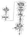
- FIG. 3 is a cross-sectional view showing a cylindrical transmission connection differential applied to an electric tricycle provided with an overrunning clutch according to the embodiment
- FIG. 4 is a cross-sectional view showing the cylindrical transmission connecting differential applied to the electric tricycle without the overrunning clutch of the embodiment
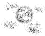
- Figure 5 is a circular cross-sectional view showing the meshing of the driving gear and the shifting gear of the transmission on the electric tricycle of the embodiment
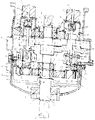
- Figure 6 is a longitudinal sectional view showing the cylindrical transmission connecting differential on the electric tricycle having the overrunning clutch of the embodiment
- Figure 7 is a schematic view of a manual shifting device of the transmission on the electric tricycle of the embodiment.
- Figure 8 is a cross-sectional view showing the transmission connecting differential on the electric tricycle without the overrunning clutch of the embodiment
- Figure 9 is a schematic view showing a spring piece disposed on a plane in the H-shaped disk of the embodiment.
- Figure 10 is a gear meshing state diagram of the automobile transmission of the embodiment.
- Figure 11 is a cross-sectional view showing the structure of a vehicle transmission connecting differential provided with an overrunning clutch according to the embodiment
- Figure 12 is a cross-sectional view showing the automotive transmission connection differential without the overrunning clutch of the embodiment
- Figure 13 is a schematic structural view of the self-holding electromagnet controlling the bottom gear of the shifting gear according to the embodiment
- Figure 14 is a view showing the components of the self-holding electromagnet of the present embodiment for controlling the lifting and lowering of the shifting gear bottom wheel;
- Figure 15 is a circular cross-sectional view showing the forward gear and the reverse gear of the automobile transmission of the embodiment
- Figure 16 is a structural view showing a reverse gear setting of the automobile transmission of the embodiment.
- Figure 17 is a schematic view showing the active gear and the input shaft in the present embodiment.
- Figure 18 is a view showing the components of the active gear and the input shaft in the present embodiment.
- Figure 19 is a schematic view showing the live connection between the upper wheel of the shifting gear and the shifting gear shaft of the present embodiment
- Figure 20 is a schematic view showing the living connection of the shifting gear bottom wheel and the shifting gear shaft of the embodiment
- Figure 21 is a schematic view showing the live connection of the upper gear of the shifting gear with the double-dial plate and the shifting gear shaft of the embodiment;
- Figure 22 is a cross-sectional view showing the structure of the center of the rotating disk and the output shaft in the present embodiment
- Figure 23 is a view showing the components of the center of the rotary disk and the output shaft in the present embodiment.
- Figure 24 is a schematic view showing the intermediate gear and the shifting gear provided in the embodiment.
- Figure 25 is a schematic view showing the control of the shifting of the self-holding electromagnet and the control of the transmission by the button block in the embodiment;
- Figure 26 is a schematic view showing the meshing condition of the gear provided with the intermediate gear, the shifting gear, and the reverse gear in the embodiment;
- Figure 27 is a cross-sectional view showing the structure of the shifting of the transmission by the steering gear of the embodiment.
- Figure 28 is a view showing the components for controlling the shifting of the transmission by the steering gear according to the embodiment.
- Figure 29 is a diagram showing the steering gear and the control button for controlling the transmission shift by the steering gear according to the embodiment.
- Figure 30 is a schematic view showing the shifting mode of the shifting of the transmission by the steering gear of the embodiment.
- Figure 31 is a cross-sectional view showing the structure of the automatic transmission which is controlled by the steering gear of the present embodiment
- Figure 32 is a cross-sectional view showing the structure of a rear-drive transmission of the electric two-wheeled vehicle of the present embodiment
- Figure 33 is a circular cross-sectional view of the transmission having the fixed flat plate of the embodiment.
- Figure 34 is a cross-sectional view showing a sprocket provided on a rear-drive transmission on the electric two-wheeled vehicle of the embodiment
- Figure 35 is a cross-sectional view showing the fourth speed transmission of the embodiment.
- Figure 36 is a cross-sectional view showing the rear transmission of the two-wheeled bicycle of the embodiment.
- Figure 37 is a cross-sectional view showing the structure of the rear-wheel drive on the two-wheeled bicycle of the embodiment.
- Figure 38 is a cross-sectional view showing the structure of a rear-drive electric vehicle transmission provided with an overrunning clutch according to the embodiment
- 39 is a cross-sectional view showing the structure of a rear-drive transmission of an electric vehicle without an overrunning clutch according to the embodiment.
- 40 is a schematic structural view showing the shifting of the transmission by the self-holding electromagnet according to the embodiment.
- Figure 41 is a schematic view showing a plurality of steering gears respectively controlling the shifting of the transmission in the embodiment
- Figure 42 is a cross-sectional view showing the transmission structure of the upper wheel provided with a plurality of shifting gears controlled by the fork control in the present embodiment
- Figure 43 is a cross-sectional view of the transmission in which the upper wheels of the plurality of shifting gears are provided in the embodiment;
- Figure 44 is a diagram showing the shifting mode in which the upper wheels of the plurality of shifting gears are provided in the embodiment.
- Figure 45 is a cross-sectional view showing the structure of a transmission provided with an intermediate gear of the embodiment.
- Figure 46 is a circular cross-sectional view of the transmission provided with the intermediate gear of the embodiment.
- Figure 47 is a cross-sectional view showing the structure of the shifting of the sheave of the embodiment.
- Figure 48 is a schematic view showing the arrangement of an electromagnetic automatic clutch between the engine and the transmission in the embodiment
- Figure 49 is a view showing the components of the shifting gear of the embodiment.
- Figure 50 is a schematic view showing the mechanical automatic clutch disposed between the engine and the transmission in the embodiment
- Figure 51 is a structural view showing the provision of a steering gear on the center of the front end cover of the transmission in this embodiment.
- 1-oil seal 2-transmission front end cover; 3- front end cover convex; 4-hole circlip; 5-bearing; 6-input shaft; 7-outer spline; 8--keyway; ;10-position pressure plate; 11-bevel; 12-double intermediate shift wheel; 13-outer shift gear; 14-outer shift gear shaft; 15-isosphere; 16-H dial; 17-H In-plane plane; 18-transmission center hole; 19-H dial convex; 20-solid inlaid bearing; 21-oil sump; 22-refueling valve; 23-drain valve; 24-oil plane valve; Gear; 26-speed gear upper wheel; 27-speed gear bottom wheel; 28-axis circlip; 29-fixed disk; 30-fixed disk side opening; 31-spring ring; 32-rotary disk; In-disk tooth; 34-to-be-engaged external tooth; 35-overrunning clutch; 36-compression spring; 37-distribution disk; 38-to-be-engaged internal tooth; 39-pin shaft; 40-
- the cylindrical transmission of the present embodiment includes a housing, an input shaft 6 and an output shaft 41.
- the housing comprises a plurality of discs, the disc is provided with an outer edge 69, the input shaft 6 and the output shaft 41 are arranged on the center line of a plurality of discs, and the input shaft 6 has a plurality of driving gears 25, and the output shaft 41 has
- the rotary disk 32 has a rotating disk inner tooth 33 thereon.
- the gear shaft is located at the periphery of the driving gear 25 between two adjacent discs, and the gear shaft has a plurality of gears.
- the gear is adjacent to the rotating disk 32, and one of the plurality of gears is separated or meshed with the rotating disk inner teeth 33.
- the discs are connected to each other by an outer port 69.
- the cylindrical transmission has a convex circle, an oil pan and the like, and does not completely constitute a circular surface, there are exactly the same circular faces and stops between them. This embodiment refers to a disk that conforms to this feature.
- the disc of the cylinder transmission is a convex circle, an oil pan and the like, and does not completely constitute a circular surface, there are exactly the same circular faces and stops between them.
- the casing of the cylinder transmission has a filling valve 22, an oil level valve 24, an oil pan 21, and an oil drain valve 23 on the oil pan; a port 72, a gasket 60 and a positioning pin 67 between the disc edges.
- the screw 59 and the nut 71 are connected to the outer edges 69.
- the plurality of disks of the cylindrical transmission of the present embodiment include an H-shaped disk 16, a fixed disk 29, and a transmission rear end cover 114.
- the fixed disk 29 has a fixed disk side opening 30.
- the gear shaft includes a shifting gear shaft 61, and the gear includes a shifting gear upper wheel 26 and a shifting gear bottom wheel 27.
- a plurality of driving gears 25 are fixed to the input shaft 6 between the H-shaped disk 16 and the fixed disk 29, and the fixed disk inner surface 62 is disposed below the rotating disk inner teeth 33.
- the H-shaped disk 16 side is connected to the fixed disk 29 and the transmission rear end cover 114.
- the center of the H-shaped disk 16 has a bearing 5 and an oil seal 1. There are two bearings 5 in the center of the fixed disk 29.
- the inner surface 17 of the H-shaped disk and the inner surface 62 of the fixed disk have a plurality of corresponding bearing sockets 119, and the bearing housing 119 has bearings 5 therein. Both ends of the shift gear shaft 61 are inserted into the bearings 5 in the bearing housing 119, respectively.
- the shift gear upper wheel 26 is fixed to the shift gear shaft 61.
- the shift gear bottom wheel has an internal spline 57.
- the shift gear shaft has an external spline 7, and the shift gear bottom wheel 27 is sleeved with the shift gear shaft 61 via a spline.
- a plurality of driving gears 25 mesh with the shifting gear upper wheel 26, respectively.
- Below the shifting gear bottom wheel 27 is a compression spring 36.
- the shifting gear bottom wheel 27 is adjacent to the rotating disc inner teeth 33 and maintains a gap, and the shifting gear bottom wheel 27 is separated or meshed with the rotating disc inner teeth 33.
- the transmission rear end cover 114 is disposed outside the rotary disk 32.
- a plurality of self-retaining electromagnets 53, an electromagnet base 91 and an electromagnet connector 92 are disposed on the plane 17 of the H-disk.
- the self-holding electromagnet 53 is fixed to the electromagnet base 91.
- An electromagnet push-pull rod 66 is provided in the self-holding electromagnet 53.
- the electromagnet push-pull rod 66 passes through the oil seal 1 on the electromagnet base 91 and is connected to the electromagnet connector 92.
- the electromagnet push-pull rod has a threaded fastener 94 on the top surface of the electromagnet connector.
- the shift gear shaft 61 has a shaft hole 89 and a ram 52 therein.
- the top end of the jack 52 is provided with a copper washer 157, a shaft yoke 28 and a steel ball 51, and the lower end of the jack 52 penetrates the shaft hole 89.
- the electromagnet connector 92 has a bayonet 159 on the bottom side, and the bayonet 159 is inserted in the bottom side of the copper washer 157.
- the shift gear shaft 61 has a transverse flat hole 90 therein.
- the shifting gear bottom wheel 27, the shifting gear shaft 61 and the ejector pin 52 are connected together in the transverse flat hole 90 by the dovetail screw 82, and the dovetail screw passes through the shifting gear bottom wheel and the shifting gear shaft, and is screwed to the shifting gear bottom wheel and the other In the side of the thread.
- a plurality of self-holding electromagnets 53 are disposed on the plane 17 of the H-shaped disk.
- An electromagnet push-pull rod 66 is provided in the self-holding electromagnet 53.
- the shift gear shaft 61 has a shaft hole 89 therein, and the shaft hole 89 is provided with a jack 52 and a steel ball 51.
- the electromagnet push-pull rod 66 is inserted into the shaft hole 89.
- the shifting gear shaft 61 has a transverse flat hole 90.
- the horizontal flat hole 90 is provided with a pin 39.
- the pin 39 is located above the shifting gear bottom wheel 27, and a spring ring 31 is disposed below the shifting gear bottom wheel.
- the top end of the output shaft 41 penetrates the bearing 5 at the center of the fixed disk 29, and the outer periphery of the output shaft 41 and the center of the rotary disk 32 have a bearing 5 and an overrunning clutch 35.
- the output shaft 41 on the side of the overrunning clutch 35 has a compression spring 36 and a splitter disk 37.
- the output shaft 41 has an output gear 42 at its bottom end.
- the center of the bottom end of the output shaft 41 has a steel ball 51 and a ram 52 therein.
- the transmission rear end cover 114 has an oil seal end cover 50, and the oil seal end cover 50 has a self-holding electromagnet 53 thereon.
- the output shaft has an external spline 7 with an internal spline 57 therein, and the splitter disc 37 is sleeved with the output shaft 41 via a spline.
- the output shaft 41 is provided with a lateral flat hole 90, and the top end of the splitter disk 37 is provided with a pin 39 that cooperates with the lateral flat hole 90.
- On one side of the rotating disc there is a coupling flange 87, and the separating disc has a coupling groove 88, and the separating disc 37 is separated or engaged with the center side of the rotating disc 32.
- the center of the rotary disk 32 is fixed to the output shaft 41.
- the top end of the output shaft 41 penetrates the bearing 5 at the center of the fixed disk 29.
- the bottom end of the output shaft 41 has an output gear 42, and the bottom end of the output shaft 41 is inserted.
- An oil seal end cap 50 is provided on the rear end of the transmission.
- the top end of the output shaft 41 penetrates the bearing 5 at the center of the fixed disk 29, and the outer periphery of the output shaft 41 and the center of the rotary disk 32 have a bearing 5 and an overrunning clutch 35.
- the output shaft 41 on the side of the overrunning clutch 35 has a splitter disk 37.
- the split disk 37 is sleeved with the output shaft 41 by splines.
- the split disk 37 is separated or engaged from the center side of the rotary disk 32.
- the bottom end of the output shaft 41 passes through the bearing 5 of the transmission rear end cover 114 and the oil seal 1.
- the inner wall of the rear end cover 114 of the transmission has a top rod limiting plate 142, a top rod 52 and a shifting fork 96.
- the shifting fork 96 is inserted into the outer edge of the groove 103 provided on the splitter disc 37.
- a compression spring 36 is disposed on the outer edge of the jack 52, and a self-retaining electromagnet 53 is disposed on the transmission rear end cover 114 at the bottom end of the jack 52.
- the jack 52 passes through a hole in the transmission rear end cover 114 and the jack stop plate 142.
- the gear shaft also includes an intermediate gear shaft 109.
- the gear also includes an intermediate gear upper wheel 106 and an intermediate gear bottom wheel 107.
- the driving gear 25 is fixed to the input shaft 6 between the flat surface 17 of the H-shaped disk and the fixed disk 29.
- the drive gear 25 meshes with the intermediate gear upper wheel 106 or the intermediate gear bottom wheel 107, and the intermediate gear upper wheel 106 or the intermediate gear bottom wheel 107 meshes with the shift gear upper wheel 26.
- the gear further includes a reverse gear 100.
- the shifting gear bottom wheel 27 and the reverse gear 100 are disposed above the rotating disk inner teeth 33, and the shifting gear bottom wheel 27 is separated or meshed with the rotating disk inner teeth 33.
- the reverse gear 100 meshes with the shift gear bottom wheel 27.
- the reverse gear 100 is fixed to the fixed disk inner plane 62 by a reverse gear shaft 99.
- the outer edge of the reverse gear shaft 99 has a compression spring 36, and the top end of the reverse gear shaft 99 has a flat washer 80 and a shaft circlip 28. Below the compression spring 36 is a seesaw 101.
- the center of the reverse gear 100 has an outer rib bushing 113, and the reverse gear shaft 99 has a solid inlaid bearing 20.
- the shift control device includes a shift fork 97 and a first shift fork 96.
- the shift fork lever 97 is disposed between the H-disc inner plane 17 and the fixed disc inner plane 62 and passes through the H-disk inner plane 17.
- the first fork 96 is fixed to the shift fork 97 and is inserted in the reverse gear The outer edge of the groove 103 on the top end of the gear 100.
- the reverse gear 100 is disengaged or meshed with the inner teeth 33 of the rotary disk.
- a synchronizer 144 is disposed between the two adjacent shifting gear upper wheels 26, and the synchronizer 144 is sleeved with the shifting gear shaft 61 via a spline having an internal spline 57 on the shifting gear shaft.
- the synchronizer is provided with internal teeth 38 to be engaged, and the upper gear wheel 26 is provided with external teeth 34 to be engaged with the internal teeth 38 to be engaged.
- the shifting gear bottom wheel 27 is fixed to the shifting gear shaft 61 and meshes with the rotating disc inner teeth 33.
- a needle bearing 143 is provided between the plurality of shifting gear upper wheels 26 and the shifting gear shaft 61.
- the shifting device further includes a second shift fork 96 that is inserted into the outer edge of the recess 103 of the synchronizer 144 disposed on the shifting gear shaft 61.
- the structure of the automatic transmission control device for the cylindrical transmission of the present embodiment includes: a plurality of self-retaining electromagnets on the plane 17 of the H-shaped disk.
- the self-holding electromagnet 53 has a wire 86 connected to the electronic automatic controller 81.
- the periphery of the rotary disk 32 of the transmission rear end cover 114 has a torque sensor 84 and a revolution number sensor 85.
- the motor 55 has a charge sensor.
- the torque sensor 84, the revolution number sensor 85, and the current sensor 83 have a wire 86 connected to the electronic automatic controller 81, and a shift sensor can be provided in the electronic automatic controller.
- the drive gear 25 has an extension sleeve 116 with internal splines 57 therein.
- the extension sleeve 116 passes through the solid inlaid bearing 20 at the center of the H-shaped disk 16, and the end of the extension sleeve 116 has a circlip for the shaft.
- the end of the input shaft 6 has an external spline 7.
- the input shaft 6 passes through the drive shaft tube 117 of the external drive and then penetrates into the center of the H-shaped disk 16 and the extension sleeve 116.
- the inner circumference of the driving gear 25 has a first groove 103.
- the input shaft 6 of the inner circumference of the driving gear 25 has a first lateral flat hole 90, and the first horizontal flat hole 90 has a first dial. 102.
- the first groove 103 is sleeved into the outer edge of the first dial 102, and the upper side of the driving gear 25 has a first flat washer 80 and a first shaft circlip 28 .
- the inner wheel of the shifting gear upper wheel 26 has a second groove 103
- the shifting gear shaft 61 in the inner circle of the upper wheel of the shifting gear 26 has a second lateral flat hole 90
- the second lateral flat hole 90 has a second dial plate 102.
- the second groove 103 is fitted into the outer edge of the second dial 102.
- the upper side of the upper wheel 26 of the shifting gear has a second flat washer 80 and a second shaft circlip 28.
- the shift gear bottom wheel 27 has a third recess 103 in the inner circumference thereof.
- the shift gear shaft 61 at the center of the inner circumference of the shift gear bottom wheel 27 has a third lateral flat hole 90, and the third transverse flat hole 90 has a third recess.
- the third groove 103 is fitted into the outer edge of the third dial 102, and the third flat washer 80 and the third shaft circlip 28 are provided on the lower side of the shift gear bottom wheel 27.
- the inner circumference of the rotary disk 32 has a fourth recess 103.
- the output shaft 41 at the center of the rotary disk 32 has a fourth lateral flat hole 90.
- the fourth lateral flat hole 90 has a fourth dial 102 therein.
- the fourth groove 103 is fitted into the outer edge of the fourth dial 102, and the inner side of the rotary disk 32 on the output shaft 41 has a fourth flat washer 80 and a fourth shaft circlip 28.
- the upper wheel of the shifting gear 26 has a second groove 103 therein, and the shifting gear shaft 61 at the center of the inner circumference of the upper wheel of the shifting gear 26 has two opposite fourth dials 102, and the second groove 103 The outer edges of the two fourth dials 102 are nested.
- the upper side of the shifting gear upper wheel 26 has a second flat washer 80 and a second shaft circlip 28 .
- one end of the output shaft 41 penetrates the bearing 5 at the center of the fixed disk 29, and the other end of the output shaft 41 passes through the bearing 5 and the oil seal 1 in the rear end cover 114 of the transmission.
- the center of the rotary disk 32 is fixed to the output shaft 41.
- the automatic gear control can be simply realized, and the electronic automatic controller controls different self-holding electromagnets according to the data output by the sensors, and controls the separation of the bottom gear of the shifting gear and the teeth of the rotating disk to realize the separation.
- Automatic shifting Compared with other existing automatic transmissions, it has the advantages of small size, low cost and simple operation, which avoids the complexity and cumbersome of the dual clutch transmission and avoids the excessive fuel consumption of the hydraulic automatic transmission.
- Hydraulic automatic transmission, dual clutch transmission, stepless change The speed converter is difficult to configure with the electric motor of the electric vehicle, and the cylindrical transmission of the present embodiment has a small size, a large speed difference, and a low cost because of its own cylindrical shape, so that it can form a good configuration with the motor, resulting in a kind of A new, cost-effective automatic transmission.
- several discs of the cylindrical transmission of the embodiment include a transmission front end cover 2 , an H-shaped disk 16 , a fixed disk 29 , and a transmission.
- the transmission rear case 43 and the differential case 44 constitute an integrated structure.
- the two adjacent discs are an H-shaped disc 16 and a fixed disc 29, and the fixed disc 29 has a fixed disc side opening 30, and the fixed disc inner plane 62 is disposed below the rotating disc inner teeth 33.
- the gear shaft includes a shifting gear shaft 61.
- the gear includes a shifting gear upper wheel 26 and a shifting gear bottom wheel 27, or the gear is a shifting single gear 70.
- the drive gear 25 is fixed to the end of the input shaft 6 between the H-shaped disk 16 and the fixed disk 29.
- the inner surface 17 of the H-shaped disk and the inner surface 62 of the fixed disk have a plurality of corresponding bearing sockets 119, and the bearing socket 119 has a solid inlaid bearing 20 therein.
- the shift gear upper wheel 26 and the shift gear bottom wheel 27 are fixed to the shift gear shaft 61 between the H-shaped disk 16 and the fixed disk 29.
- the shift gear shaft 61 is below the transmission front end cover 2, and the center of the top end of the shift gear shaft 61 has a steel ball 51.
- the top end of the shifting gear shaft 61 passes through the solid inlaid bearing 20 in the plane 17 of the H-shaped disc.
- the bottom end of the shifting gear shaft 61 penetrates into the solid inlaid bearing 20 in the plane 62 of the fixed disc, and the bottom surface of the flat surface 62 of the fixed disc has
- the spring coil 31 has a steel ball 51 and a column head 63 in the axial center of the bottom end of the transmission gear shaft 61.
- the shifting gear bottom wheel 27 is adjacent to the rotating disc inner teeth 33 and maintains a gap.
- the drive gear 25 meshes with the shift gear upper wheel 26.
- the shifting gear bottom wheel 27 is disengaged or meshed with the rotating disc inner teeth 33.
- the H-shaped disk 16 is connected to the transmission front end cover 2 on one side, and the other side of the H-shaped disk 16 is connected to the fixed disk 29 and the transmission rear case 43.
- the top end of the output shaft 41 penetrates the bearing 5 at the center of the fixed disk 29, and the output shaft 41 A bearing 5 and an overrunning clutch 35 are provided between the outer edge and the center of the rotary disk 32.
- the output shaft 41 on the side of the overrunning clutch 35 has a compression spring 36 and a splitter disk 37.
- the output shaft 41 has an output gear 42 at its bottom end, and an output gear 42 is disposed in the differential case 44.
- the output gear 42 is sequentially engaged with the intermediate gear 64 and the driven gear 49 in the differential case 44.
- the bottom end of the output shaft 41 penetrates into the bearing 5 of the outer side 46 of the differential.
- the differential outer side 46 has a self-holding electromagnet 53 and an oil seal end cover 50.
- the self-holding electromagnet 53 has an electromagnet push-pull rod 66, and the self-holding electromagnet 53 is disposed at the bottom end of the output shaft 41.
- the output shaft 41 is provided with a transverse flat hole 90 and a key 40. Usually, two keys which are crossed with the horizontal flat hole are provided, and the split disk 37 is sleeved with the output shaft 41 through the key 40.
- the center of the bottom end of the output shaft 41 has a steel ball 51 and a ram 52 therein.
- the top end of the splitter disk 37 is provided with a pin 39 that cooperates with the lateral flat hole 90.
- the inner side of the rotating disc 32 is separated or engaged with the splitter disc 37. On one side of the rotating disc, there is an external tooth 34 to be engaged, and the inner disc 38 is to be engaged in the split disc. There are bearings 5 between the ends of the gear shaft 65 and the differential inner side 45 and the differential outer side 46.
- the application of the overrunning clutch is equivalent to neutral slip.
- Multi-axis series transmissions cannot be shifted without a clutch.
- the cylindrical transmission of the embodiment has been tested, and it can perform clutchless shifting itself, and the application of the overrunning clutch can realize smooth shifting of the vehicle during operation, increase the sliding distance of the electric vehicle, and improve efficiency and save energy.
- the existing gearbox when the driver lifts the power pedal, the vehicle will decelerate immediately. From the wheel to the gearbox to the engine, the vehicle will have a great retardation effect, which will not only cause energy waste, but also be unnecessary. Causes engine fatigue and reduces efficiency.
- the vehicle when the driver lifts the power pedal, the vehicle does not rotate with the motor, so that the transmission shifts smoothly in a static state, and the vehicle runs normally, which can improve efficiency and reduce motor fatigue. .
- the self-holding electromagnet When the driver brakes on the brakes, the self-holding electromagnet is energized, the split disc and the rotating disc are combined to make the power, and the motor or the engine also has a resistance to the vehicle. The hysteresis slows down the vehicle.
- the cylindrical transmission of the embodiment does not use a clutch, which saves a lot of cost and avoids the cumbersomeness of the driver to constantly step on the clutch pedal.
- the center of the rotary disk 32 is fixed to the output shaft 41, and the top end of the output shaft 41 penetrates the bearing 5 at the center of the fixed disk 29.
- the output shaft 41 has an output gear 42 at its bottom end, and an output gear 42 is disposed in the differential case 44.
- the output gear 42 is sequentially engaged with the intermediate gear 64 and the driven gear 49 in the differential case 44.
- the bottom end of the output shaft 41 penetrates into the bearing 5 of the outer side 46 of the differential.
- An oil seal end cap 50 is provided on the outer side 46 of the differential.
- the transmission front end cover 2 and the H-shaped inner plane 17 are provided with a dial sleeve wheel 9, a double intermediate shift wheel 12, an outer shift gear 13, an outer shift gear shaft 14, and a gear position.
- the gear platen 10 is fixed to the dial wheel 9 and the gear platen 10 is provided with a slope 11.
- the dial wheel 9 is disposed on the outer edge of the input shaft 6.
- the center of the H-shaped disk below the dial wheel has an isolating ring 15 which is engaged with the dial wheel 9 and the outer dial gear 13, respectively.
- the outer shift gear 13 is fixed to the outer shift gear shaft 14, and the outer shift gear shaft 14 extends out of the front end cover 2.
- a gear pull plate 54 is fixed to one end of the outer shift gear shaft 14.
- the top end of the shift gear shaft 61 has a steel ball 51 having a copper washer 157 and a shaft circlip 28 on the upper portion.
- the shifting gear shaft 61 passes upward through the H-disc inner plane 17.
- the spring piece 68 is fixed to the inner surface 17 of the H-shaped disk by a screw 59.
- the spring piece 68 is disposed below the copper washer 157.
- a dial sleeve 9 between the transmission front end cover 2 and the H-shaped inner plane 17, a dial sleeve 9, a shift intermediate single gear 146, an outer shift gear 13, an outer shift gear shaft 14, and a shift platen 10 are disposed.
- the gear platen 10 is fixed to the dial wheel 9 and the gear platen 10 is provided with a slope 11.
- the outer shift gear 13 is fixed to the outer shift gear shaft 14, and the outer shift gear shaft 14 extends out of the front end cover 2.
- the drive gear 25 has an extension sleeve 116 with internal splines 57 therein.
- the extension sleeve 116 passes through the solid inlaid bearing 20 at the center of the H-shaped disk 16, and the end of the extension sleeve 116 has a circlip for the shaft.
- the end of the input shaft 6 has an external spline 7.
- the input shaft 6 passes through the drive shaft tube 117 of the external drive and then penetrates into the center of the H-shaped disk 16 and the extension sleeve 116.
- the inner circumference of the driving gear 25 has a first groove 103.
- the input shaft 6 of the inner circumference of the driving gear 25 has a first lateral flat hole 90, and the first horizontal flat hole 90 has a first dial. 102.
- the first groove 103 is sleeved into the outer edge of the first dial 102, and the upper side of the driving gear 25 has a first flat washer 80 and a first shaft circlip 28 .
- the upper wheel of the shifting gear 26 has a second recess 103 therein.
- the shifting gear shaft 61 in the inner circumference of the upper wheel of the shifting gear 26 has a second lateral flat hole 90, and the second transverse flat hole 90 has a second recess.
- the second groove 103 is fitted into the outer edge of the second dial 102.
- the upper side of the upper wheel 26 of the shifting gear has a second flat washer 80 and a second shaft circlip 28.
- the shift gear bottom wheel 27 has a third recess 103 in the inner circumference thereof.
- the shift gear shaft 61 at the center of the inner circumference of the shift gear bottom wheel 27 has a third lateral flat hole 90, and the third transverse flat hole 90 has a third recess.
- the third groove 103 is fitted into the outer edge of the third dial 102, and the third flat washer 80 and the third shaft circlip 28 are provided on the lower side of the shift gear bottom wheel 27.
- the inner circumference of the rotary disk 32 has a fourth recess 103.
- the output shaft 41 at the center of the rotary disk 32 has a fourth lateral flat hole 90.
- the fourth lateral flat hole 90 has a fourth dial 102 therein.
- the fourth groove 103 is fitted into the outer edge of the fourth dial 102, and the inner side of the rotary disk 32 on the output shaft 41 has a fourth flat washer 80 and a fourth shaft circlip 28.
- the upper wheel of the shifting gear 26 has a second groove 103 therein, and the shifting gear shaft 61 at the center of the inner circumference of the upper wheel of the shifting gear 26 has two opposite fourth dials 102, and the second groove 103 Nested into two The outer edge of the fourth dial 102.
- the upper side of the shifting gear upper wheel 26 has a second flat washer 80 and a second shaft circlip 28 .
- the gear shaft of the cylindrical transmission of the present embodiment may further include an intermediate gear shaft 109; the gear further includes an intermediate gear upper wheel 106 and an intermediate gear bottom wheel 107; further, the gear may further include a reverse gear 100, and the reverse gear 100
- a shift control device is disposed on one side; a synchronizer 144 is disposed between the upper wheels of two adjacent shift gears.
- the cylindrical transmission of this embodiment is designed in multiple gear positions.
- the existing multi-shaft full-series transmission can only achieve shifting on one shaft outside the input shaft, and the cylindrical transmission of the embodiment can realize shifting on multiple shafts, and a plurality of shafts can be arranged in the outer circumference of the input shaft.
- a plurality of shifting gear upper wheels can be designed on each shaft to realize multiple gears, and the rotating discs respectively transmit power. For example, if four upper gears are provided on each axis and four axes are placed around the input shaft, different outputs of 16 gears will be realized in a small volume.
- the plurality of disks of the cylindrical transmission of the present embodiment include an H-shaped disk 16, a fixed flat disk 121, and a transmission rear end cover 114.
- the gear shaft includes a shifting gear shaft 61.
- the gear includes a shifting gear upper wheel 26, a shifting gear bottom wheel 27, and a shifting single gear 70.
- the H-shaped inner plane 17 and the fixed flat plate 121 have a plurality of fixing posts 130.
- the H-shaped inner plane 17 and the fixed flat disk 121 have a plurality of corresponding bearing sockets 119, and the bearing sockets 119 have solid inlaid bearings 20 therein. .
- the outer periphery of the input shaft 6 has a driving gear 25, and the shifting gear upper wheel 26 and the shifting gear bottom wheel 27 are fixed to the shifting gear shaft 61, and the top end of the shifting gear shaft 61 has a steel ball 51. .
- the shifting gear shaft 61 passes upward through the H-disc inner plane 17. Below the shifting gear bottom wheel 27 is a compression spring 36. Bottom of the shifting gear shaft 61
- the outer rim bushing 113 is inserted into the outer ferrule bushing 113 in the fixed flat disk 121, and the outer ferrule bushing 113 is disposed in the solid inlaid bearing 20 in the fixed flat disk 121.
- the fixed flat disk 121 is disposed under the rotating disk inner teeth 33.
- the drive gear 25 meshes with the shift gear upper wheel 26, the shift gear bottom wheel 27 is adjacent to the rotary disc inner teeth 33 and maintains a gap, and the shift gear bottom wheel 27 is disengaged or meshed with the rotary disc inner teeth 33.
- the outer port 69 of the H-shaped disk 16 is coupled to the outer port 69 of the rear end cover 114 of the transmission.
- the center of the rotary disk 32 is fixed to the output shaft 41.
- One end of the output shaft 41 penetrates the bearing 5 fixed to the center of the flat plate 121, and the other end of the output shaft 41 passes through the bearing 5 and the oil seal 1 in the rear end cover 114 of the transmission.
- the outer end of the output shaft 41 passes through the transmission rear end cover 114 and the overrunning clutch 35 at the center of the hub disk 122.
- the outer end of the output shaft 41 is provided with a nut 71 and a thrust pad 140.
- the drive gear 25 has an extension sleeve 116 with internal splines 57 therein.
- the extension sleeve 116 passes through the solid inlaid bearing 20 at the center of the H-shaped disk 16, and the end of the extension sleeve 116 has a circlip for the shaft.
- the end of the input shaft 6 has an external spline 7.
- the input shaft 6 passes through the drive shaft tube 117 of the external drive and then penetrates into the center of the H-shaped disk 16 and the extension sleeve 116.
- the inner circumference of the driving gear 25 has a first groove 103.
- the input shaft 6 of the inner circumference of the driving gear 25 has a first lateral flat hole 90, and the first horizontal flat hole 90 has a first dial. 102.
- the first groove 103 is sleeved into the outer edge of the first dial 102, and the upper side of the driving gear 25 has a first flat washer 80 and a first shaft circlip 28 .
- the upper wheel of the shifting gear 26 has a second recess 103 therein.
- the shifting gear shaft 61 in the inner circumference of the upper wheel of the shifting gear 26 has a second lateral flat hole 90, and the second transverse flat hole 90 has a second recess.
- the second groove 103 is fitted into the outer edge of the second dial 102.
- the upper side of the upper wheel 26 of the shifting gear has a second flat washer 80 and a second shaft circlip 28.
- the shift gear bottom wheel 27 has a third recess 103 in the inner circumference thereof.
- the shift gear shaft 61 at the center of the inner circumference of the shift gear bottom wheel 27 has a third lateral flat hole 90, and the third transverse flat hole 90 has a third recess.
- the third groove 103 is fitted into the outer edge of the third dial 102, and the third flat washer 80 and the third shaft circlip 28 are provided on the lower side of the shift gear bottom wheel 27.
- the inner circumference of the rotary disk 32 has a fourth recess 103.
- the output shaft 41 at the center of the rotary disk 32 has a fourth lateral flat hole 90.
- the fourth lateral flat hole 90 has a fourth dial 102 therein.
- the fourth groove 103 is fitted into the outer edge of the fourth dial 102, and the inner side of the rotary disk 32 on the output shaft 41 has a fourth flat washer 80 and a fourth shaft circlip 28.
- the upper wheel of the shifting gear 26 has a second groove 103 therein, and the shifting gear shaft 61 at the center of the inner circumference of the upper wheel of the shifting gear 26 has two opposite fourth dials 102, and the second groove 103 The outer edges of the two fourth dials 102 are nested.
- the upper side of the shifting gear upper wheel 26 has a second flat washer 80 and a second shaft circlip 28 .
- the cylindrical transmission of the present embodiment can be disposed in a rear-drive device of an electric two-wheeled motorcycle, so that the electric two-wheeled motorcycle applies a high-speed motor to generate a large torque, so that the electric two-wheeled motorcycle can obtain a large starting power and acceleration.
- the existing transmission does not have a suitable mounting position in the rear-drive device of the electric two-wheeled vehicle, and it is also impossible to complete a large reduction ratio.
- the cylindrical transmission of this embodiment since the input shaft and the output shaft are on the same center line, there is a mounting position thereof, and a large reduction ratio can be realized.
- the plurality of disks of the cylindrical transmission of the present embodiment include a transmission front end cover 2, an H-shaped disk 16, a fixed flat plate 121, and a transmission rear end cover 114.
- the inner surface 17 of the H-shaped disk and the fixed flat disk 121 have a plurality of corresponding bearing sockets 119, and the bearing socket 119 has a solid inlaid bearing 20.
- the gear shaft includes an intermediate gear shaft 109 and a shift gear shaft 61.
- the gear includes an intermediate gear upper wheel 106, an intermediate gear bottom wheel 107, a shifting gear upper wheel 26, and a shifting gear bottom wheel 27.
- the driving gear 25 is fixed to the input shaft 6 between the flat surface 17 of the H-shaped disk and the fixed flat plate 121.
- the intermediate gear upper wheel 106 and the intermediate gear bottom wheel 107 are fixed to the intermediate gear shaft 109, and the shift gear upper wheel 26 and the shift gear bottom wheel 27 are fixed to the shift gear shaft 61.
- the drive gear 25 meshes with the intermediate gear upper wheel 106 or the intermediate gear bottom wheel 107, and the intermediate gear upper wheel 106 or the intermediate gear bottom wheel 107 meshes with the shift gear upper wheel 26.
- the top end of the shifting gear shaft 61 has a steel ball 51.
- the top end of the shifting gear shaft 61 passes through the solid inlaid bearing 20 in the plane 17 of the H-shaped disc and is located below the front end cover 2 of the transmission.
- the outer end of the bottom end of the shifting gear shaft 61 has a compression spring 36.
- the bottom end of the shifting gear shaft 61 penetrates the outer rib bushing 113 in the fixed flat disc 121, and the outer rib bushing 113 is disposed in the fixed flat disc 121.
- Solid inlaid bearing 20 There are a plurality of fixing posts 130 between the H-shaped disk 16 and the fixed flat disk 121.
- the fixed flat plate and the fixed fixed disk can be mutually common as needed.
- the gear also includes an intermediate single gear 108.
- the intermediate single gear 108 is disposed between the H-shaped inner plane 17 and the fixed inner plane 62 or the fixed flat 121.
- the drive gear 25 meshes with the intermediate single gear 108, the intermediate single gear 108 meshes with the shift gear upper wheel 26, and the shift gear bottom wheel 27 is disengaged or meshed with the rotary disc inner teeth 33.
- the gear also includes a shifting single gear 70.
- the shift single gear 70 is disposed between the H-shaped inner plane 17 and the fixed inner plane 62 or the fixed flat 121.
- the intermediate gear upper wheel 106 or the intermediate gear bottom wheel 107 meshes with the shift single gear 70.
- the shift single gear 70 is disengaged or meshed with the inner teeth 33 of the rotary disk.
- the drive gear 25 has an extension sleeve 116 with internal splines 57 therein.
- the extension sleeve 116 passes through the solid at the center of the H-shaped disk 16 Inlaid bearing 20, the end of the extension sleeve 116 has a shaft circlip 28 for the shaft.
- the end of the input shaft 6 has an external spline 7.
- the input shaft 6 passes through the drive shaft tube 117 of the external drive and then penetrates into the extension sleeve 116 in the center of the H-shaped disk 16.
- the inner circumference of the driving gear 25 has a first groove 103.
- the input shaft 6 of the inner circumference of the driving gear 25 has a first lateral flat hole 90, and the first horizontal flat hole 90 has a first dial. 102.
- the first groove 103 is sleeved into the outer edge of the first dial 102, and the upper side of the driving gear 25 has a first flat washer 80 and a first shaft circlip 28 .
- the upper wheel of the shifting gear 26 has a second recess 103 therein.
- the shifting gear shaft 61 in the inner circumference of the upper wheel of the shifting gear 26 has a second lateral flat hole 90, and the second transverse flat hole 90 has a second recess.
- the second groove 103 is fitted into the outer edge of the second dial 102.
- the upper side of the upper wheel 26 of the shifting gear has a second flat washer 80 and a second shaft circlip 28.
- the shift gear bottom wheel 27 has a third recess 103 in the inner circumference thereof.
- the shift gear shaft 61 at the center of the inner circumference of the shift gear bottom wheel 27 has a third lateral flat hole 90, and the third transverse flat hole 90 has a third recess.
- the third groove 103 is fitted into the outer edge of the third dial 102, and the third flat washer 80 and the third shaft circlip 28 are provided on the lower side of the shift gear bottom wheel 27.
- the inner circumference of the rotary disk 32 has a fourth recess 103.
- the output shaft 41 at the center of the rotary disk 32 has a fourth lateral flat hole 90.
- the fourth lateral flat hole 90 has a fourth dial 102 therein.
- the fourth groove 103 is fitted into the outer edge of the fourth dial 102, and the inner side of the rotary disk 32 on the output shaft 41 has a fourth flat washer 80 and a fourth shaft circlip 28.
- the upper wheel of the shifting gear 26 has a second groove 103 therein, and the shifting gear shaft 61 at the center of the inner circumference of the upper wheel of the shifting gear 26 has two opposite fourth dials 102, and the second groove 103 The outer edges of the two fourth dials 102 are nested.
- the upper side of the shifting gear upper wheel 26 has a second flat washer 80 and a second shaft circlip 28 .
- the cylindrical transmission of the present embodiment can achieve a large reduction ratio or an acceleration ratio.
- the reduction ratio of the driving gear to the internal teeth of the rotating disc is 7:1
- the reduction ratio of the intermediate gear is 3:1
- the reduction of the transmission gear The ratio is 3:1
- the planetary reducer can complete up to 6-7 times
- the cylinder of this embodiment The transmission can achieve more than twice the reduction ratio, which is not possible with any other existing transmission, and is especially suitable for the large reduction ratio required for high speed motors.
- gearboxes people thought that electric vehicles did not use gearboxes. Now people have realized that electric vehicles do not have a transmission that cannot operate normally. Currently, electric vehicles do not have a suitable transmission available, and the cylindrical transmission of this embodiment can completely compensate for this defect.
- a plurality of disks of the cylindrical transmission of the present embodiment include a transmission front end cover 2, an H-shaped disk 16, a fixed flat plate 121, and a transmission rear end cover 114.
- the transmission front end cover 2, the H-shaped disk 16, and the fixed flat plate 121 are sleeved on the outer edge of the input shaft 6, and the input shaft 6 is a hollow shaft corresponding to the input shaft tube 135.
- the center of the input shaft 6 and the output shaft 41 has a solid inlaid bearing 20.
- the outer end of the input shaft 6 has a connecting ring 126.
- the outer edge of the connecting ring 126 has a sprocket 134.
- the H-shaped disk 16 and the fixed flat plate 121 respectively have a solid inlaid bearing 20 between the input shaft 6.
- An O-type oil seal 137 is disposed between the transmission front end cover 2 and the input shaft 6.
- the rotary disk 32 and the output shaft 41 constitute an integrated structure.
- the outer end of the output shaft 41 passes through the rear end cover 114 of the transmission, and the output shaft 41 is a hollow shaft, which corresponds to the output shaft tube 138.
- the outer edge of the output shaft 41 has a hub disk 122.
- One side of the H-shaped disk 16 is coupled to the transmission front end cover 2, and the other side of the H-shaped disk 16 is coupled to the transmission rear end cover 114.
- a dial sleeve 9, an outer shift gear 13, an outer shift gear shaft 14, a shift plate 10, and a sheave 139 are disposed between the transmission front end cover 2 and the H-shaped inner plane 17, a dial sleeve 9, an outer shift gear 13, an outer shift gear shaft 14, a shift plate 10, and a sheave 139 are disposed.
- the gear platen 10 is fixed to the dial wheel 9 and the gear platen 10 is provided with a slope 11.
- the dial wheel 9 is disposed on the outer edge of the input shaft 6, and the dial wheel 9 and the outer dial gear 13 are engaged.
- the outer shift gear 13 is fixed to the outer dial On the gear shaft 14, the outer shift gear shaft 14 extends out of the transmission front end cover 2.
- a sheave 139 is fixed to one end of the outer shift gear shaft 14.
- the gear shaft includes an intermediate gear shaft 109 and a shift gear shaft 61.
- the gear includes an intermediate gear upper wheel 106, an intermediate gear bottom wheel 107, a shifting gear upper wheel 26, and a shifting gear bottom wheel 27.
- the driving gear 25 is fixed to the input shaft 6 between the flat surface 17 of the H-shaped disk and the fixed flat plate 121.
- the center of the rotary disk 32 is fixed to the output shaft 41.
- the intermediate gear upper wheel 106 and the intermediate gear bottom wheel 107 are fixed to the intermediate gear shaft 109, and the shift gear upper wheel 26 and the shift gear bottom wheel 27 are fixed to the shift gear shaft 61.
- the drive gear 25 meshes with the intermediate gear upper wheel 106 or the intermediate gear bottom wheel 107, and the intermediate gear upper wheel 106 or the intermediate gear bottom wheel 107 meshes with the shift gear upper wheel 26.
- the top end of the shifting gear shaft 61 has a steel ball 51.
- the top end of the shifting gear shaft 61 passes through the solid inlaid bearing 20 in the plane 17 of the H-shaped disc and is located below the front end cover 2 of the transmission.
- the outer end of the bottom end of the shifting gear shaft 61 has a compression spring 36.
- the bottom end of the shifting gear shaft 61 penetrates the outer rib bushing 113 in the fixed flat disc 121, and the outer rib bushing 113 is disposed in the fixed flat disc 121.
- the drive gear 25 has an extension sleeve 116 with internal splines 57 therein.
- the extension sleeve 116 passes through the solid inlaid bearing 20 at the center of the H-shaped disk 16, and the end of the extension sleeve 116 has a circlip for the shaft.
- the end of the input shaft 6 has an external spline 7.
- the input shaft 6 passes through the drive shaft tube 117 of the external drive and then penetrates into the center of the H-shaped disk 16 and the extension sleeve 116.
- the inner circumference of the driving gear 25 has a first groove 103.
- the input shaft 6 of the inner circumference of the driving gear 25 has a first lateral flat hole 90, and the first horizontal flat hole 90 has a first dial. 102.
- the first groove 103 is sleeved into the outer edge of the first dial 102, and the upper side of the driving gear 25 has a first flat washer 80 and a first shaft circlip 28 .
- the inner wheel of the shifting gear 26 has a second groove 103 in the inner circle, and the shifting gear in the inner circle of the upper wheel 26 of the shifting gear
- the shaft 61 has a second lateral flat hole 90 therein, and the second lateral flat hole 90 has a second dial 102 therein.
- the second groove 103 is fitted into the outer edge of the second dial 102.
- the upper side of the upper wheel 26 of the shifting gear has a second flat washer 80 and a second shaft circlip 28.
- the shift gear bottom wheel 27 has a third recess 103 in the inner circumference thereof.
- the shift gear shaft 61 at the center of the inner circumference of the shift gear bottom wheel 27 has a third lateral flat hole 90, and the third transverse flat hole 90 has a third recess.
- the third groove 103 is fitted into the outer edge of the third dial 102, and the third flat washer 80 and the third shaft circlip 28 are provided on the lower side of the shift gear bottom wheel 27.
- the inner circumference of the rotary disk 32 has a fourth recess 103.
- the output shaft 41 at the center of the rotary disk 32 has a fourth lateral flat hole 90.
- the fourth lateral flat hole 90 has a fourth dial 102 therein.
- the fourth groove 103 is fitted into the outer edge of the fourth dial 102, and the inner side of the rotary disk 32 on the output shaft 41 has a fourth flat washer 80 and a fourth shaft circlip 28.
- the upper wheel of the shifting gear 26 has a second groove 103 therein, and the shifting gear shaft 61 at the center of the inner circumference of the upper wheel of the shifting gear 26 has two opposite fourth dials 102, and the second groove 103 The outer edges of the two fourth dials 102 are nested.
- the upper side of the shifting gear upper wheel 26 has a second flat washer 80 and a second shaft circlip 28 .
- the current bicycle shifting speed is mostly multi-layer chain shifting, and the multi-layer chain shifting is easy to cause the sprocket and the chain to wear, making the shifting difficult.
- the input shaft and the output shaft of the cylindrical transmission of the embodiment can be placed on the rear axle of the bicycle, and the mechanical shifting of the bicycle is completed with a small volume, the cost is low, the gear is not easily damaged, and the application performance of the bicycle can be improved.
- the cylindrical transmission of the embodiment can be mechanically shifted on various shafts to increase the application range.
- FIG. 7 is a schematic diagram of a manual shifting device of the transmission on the electric tricycle, wherein: one end of the shifting pull plate 74 is fixed to the front end cover 2 of the transmission, and the other end of the shifting pull plate 74 is connected to one end of the shifting wire 75; The other end of the pull wire 75 is connected to the bottom end of the shift lever 77 in the shifter case 76; the middle and lower part of the shift lever 77 has a ball screw 79, and the ball screw 79 connects the shift lever to the side of the shifter case 76. ; shifter box 76 There is a gear track slot 78 thereon.
- the above-exemplified embodiment can also adopt the following shifting mode: Referring to FIG. 44, a plurality of self-holding electromagnets 53 are mounted on the plane 17 of the H-shaped disc, and the self-holding electromagnet 53 is fixed to the electromagnet. On the base 91, the electromagnet base 91 is fixed on the inner surface 17 of the H-shaped disk.
- the electromagnet push-pull rod 66 in the self-holding electromagnet 53 is connected to the electromagnet connector 92, and the bayonet 159 in the electromagnet connector 92 is stuck.
- the shaft of the upper end of the jack 52 provided at the center of the shift gear shaft 61 is provided with a circlip 28 and a bottom side of the copper washer 158.
- the jack 52 at the center of the shift gear shaft 61 penetrates into the shaft center of the shift gear shaft 61.
- the shift gear bottom wheel 27 is fixed to the lower end of the shift gear shaft 61, and the shift gear bottom wheel 27 meshes with the rotary disc inner teeth 33; a needle bearing 143 is provided between the shift gear upper wheel 26 and the shift gear shaft 61.
- a synchronizer 144 is disposed between the two adjacent shifting gear upper wheels 26.
- the synchronizer has an internal spline 57 sleeved on the outer edge of the external spline 7 provided on the shifting gear shaft 61, and the shifting gear shaft 61 has a transverse flat hole 90.
- the dovetail screw 82 passes transversely through the synchronizer 144 and through the ram 52 in the transverse flat bore.
- the above-exemplified embodiments may also adopt the following shifting mode: Referring to Figures 47 and 49, the driving gear 25 has an extension sleeve 116, and the extension sleeve 116 has internal splines 57 therein.
- the extension sleeve 116 passes through the solid inlaid bearing 20 in the H-shaped disk 16, and the end of the extension sleeve 116 has a shaft that is restrained by the circlip 28 .
- the inner spline ferrule 118 is fixed with a gear pressing plate 10, and the inner spline ferrule 118 has an inner spline 57 therein.
- the spoke wheel connecting pipe 155 has external splines 7 at both ends of the end, and the H-shaped disk 16 and the front end of the transmission In the cover 2, the inner end of the sheave connecting pipe 155 penetrates into the inner spline ferrule 118, and the end of the sheave connecting pipe 155 has a shaft circlip 28 for the shaft.
- the sheave connecting tube 155 passes outwardly through the solid inlaid bearing 20 and the oil seal 1 in the front end cover 2 of the transmission.
- a shaft circlip 28 is provided above the solid inlaid bearing 20 in the transmission front end cover 2 at the outer edge of the sheave connecting tube 155.
- the groove 139 has an inner spline 57 which is sleeved on the outer edge of the outer spline 7 of the sheave connecting pipe 155.
- the outer end of the sheave connecting pipe 155 has a shaft circlip 28, a sheave connecting pipe 155 and a front end cover of the motor 55. There is a stop 72 between them.
- the input shaft 6 is integral with the motor shaft 56.
- the input shaft 6 has an external spline 7 at its end.
- the input shaft 6 passes through the sheave connecting tube 155 and penetrates into the internal spline 57 of the driving gear 25 extending sleeve 116.
- the outer edge of the input shaft 6 in the sheave connecting pipe 155 has an O-ring 137.
- the cord ends 148 of the two flexible wires 149 have a threaded button 94.
- the holes in the peripheral wall of the front end cover 2 of the transmission have a thread 94.
- the ends of the two oil wires 147 have a oil column head 150 and a oil column head. 150 is docked in the stud docking hole 154 provided on the sheave 139.
- FIG. 48 and FIG. 50 are schematic diagrams showing the application connection of the cylinder transmission and the fuel engine of the present embodiment, wherein the electromagnetic engine 153 is interposed between the fuel engine 151 and the cylinder transmission; the engine output shaft 152 of the fuel engine 151 is electromagnetically inserted from one side.
- the automatic clutch 153 the input shaft 6 of the cylindrical transmission is inserted into the electromagnetic automatic clutch 153 from the other side; there is a mechanical automatic clutch 156 between the fuel engine 151 and the cylindrical transmission; the engine output shaft 152 of the fuel engine 151 is inserted from one side
- the mechanical automatic clutch 156 the input shaft 6 of the cylindrical transmission is inserted into the mechanical automatic clutch 156 from the other side.
- Figure 51 is a structural view showing the setting of the steering gear on the center of the front end cover of the transmission in the embodiment, wherein the front end cover 2 of the transmission is connected to the H-shaped disk 16, the driving gear 25 has an extending sleeve 116, and the inner sleeve 116 has internal splines 57.
- the extension sleeve 116 passes through the solid inlaid bearing 20 in the H-shaped disk 16, and the end of the extension sleeve 116 has a circlip for the shaft.
- the steering gear 112 is fixed outside the center of the transmission front end cover 2, and the steering gear drive shaft tube 117 in the steering gear 112 passes through the oil seal 1 and the solid inlaid bearing 20 in the transmission front end cover 2.
- the gear plate 10 is fixed to the side of the inner spline ferrule 118, and the inner spline ferrule 118 has an inner spline 57 which is sleeved on the steering drive shaft tube 117.
- the outer edge of the outer spline 7 and the end of the steering gear drive shaft have a circlip for the shaft 28 .
- the input shaft 6 passes through the steering drive shaft tube 117 in the steering gear 112 and penetrates into the extension sleeve 116 of the drive gear 25.
- An O-ring 137 is provided on the outer edge of the input shaft 6 in the steering gear drive shaft tube 117.
Landscapes
- Engineering & Computer Science (AREA)
- General Engineering & Computer Science (AREA)
- Mechanical Engineering (AREA)
- General Details Of Gearings (AREA)
- Structure Of Transmissions (AREA)
- Transmissions By Endless Flexible Members (AREA)
Priority Applications (2)
| Application Number | Priority Date | Filing Date | Title |
|---|---|---|---|
| EP16739789.2A EP3249262A4 (de) | 2015-01-20 | 2016-01-20 | Zylindrisches getriebe |
| US15/545,226 US10690221B2 (en) | 2015-01-20 | 2016-01-20 | Cylindrical transmission |
Applications Claiming Priority (2)
| Application Number | Priority Date | Filing Date | Title |
|---|---|---|---|
| CN201510026334.0 | 2015-01-20 | ||
| CN201510026334 | 2015-01-20 |
Publications (1)
| Publication Number | Publication Date |
|---|---|
| WO2016116042A1 true WO2016116042A1 (zh) | 2016-07-28 |
Family
ID=56042041
Family Applications (1)
| Application Number | Title | Priority Date | Filing Date |
|---|---|---|---|
| PCT/CN2016/071441 WO2016116042A1 (zh) | 2015-01-20 | 2016-01-20 | 圆柱体变速器 |
Country Status (4)
| Country | Link |
|---|---|
| US (1) | US10690221B2 (de) |
| EP (1) | EP3249262A4 (de) |
| CN (2) | CN205331387U (de) |
| WO (1) | WO2016116042A1 (de) |
Cited By (4)
| Publication number | Priority date | Publication date | Assignee | Title |
|---|---|---|---|---|
| CN109129010A (zh) * | 2018-11-14 | 2019-01-04 | 浙江双正机床有限公司 | 一种可自动分度的同步夹具 |
| CN113154021A (zh) * | 2021-04-16 | 2021-07-23 | 江苏华永复合材料有限公司 | 带行星框架的钟形鼓总成及行星轮安装方法 |
| CN113357349A (zh) * | 2021-06-18 | 2021-09-07 | 中国第一汽车股份有限公司 | 减速器壳体结合面密封压力的预报方法 |
| US20210323604A1 (en) * | 2020-04-18 | 2021-10-21 | Ryan Nathaniel Combs | Coaxial co-located vehicle drive power and steering system |
Families Citing this family (6)
| Publication number | Priority date | Publication date | Assignee | Title |
|---|---|---|---|---|
| US10690221B2 (en) * | 2015-01-20 | 2020-06-23 | Shenzhen Huaqing Transmission Technology Co., Ltd. | Cylindrical transmission |
| DE102016220951A1 (de) * | 2016-10-25 | 2018-04-26 | Volkswagen Aktiengesellschaft | Antriebsstrang, insbesondere Hybridantriebsstrang für ein Kraftfahrzeug |
| CN108331893A (zh) * | 2017-01-20 | 2018-07-27 | 北京华擎变速器工程技术研究院 | 汽车电动车自行车用圆柱体变速器 |
| EP3750753A4 (de) * | 2018-02-11 | 2021-06-23 | BYD Company Limited | Drehmechanismus für ein anzeigegerät und fahrzeug |
| CN110939698B (zh) * | 2019-12-04 | 2022-03-01 | 西南大学 | 具有倒挡的全机械式自适应自动变速系统 |
| CN110966363B (zh) * | 2019-12-31 | 2022-03-01 | 西南大学 | 具有倒挡的中央驱动式自适应电驱动系统 |
Citations (6)
| Publication number | Priority date | Publication date | Assignee | Title |
|---|---|---|---|---|
| US3927580A (en) * | 1971-07-02 | 1975-12-23 | Lewmar Marine Ltd | Disengaging clutch systems for a three-speed winch |
| RU2017034C1 (ru) * | 1991-02-12 | 1994-07-30 | Шевелева Нина Константиновна | Коробка передач |
| CN1369656A (zh) * | 2002-03-29 | 2002-09-18 | 刘建航 | 可变比同轴变速器 |
| CN101564993A (zh) * | 2008-05-15 | 2009-10-28 | 石铭正 | 圆柱体变速箱及换挡输出装置 |
| CN202170969U (zh) * | 2011-06-29 | 2012-03-21 | 石铭正 | 电动车圆柱体变速箱 |
| JP2013108611A (ja) * | 2011-11-24 | 2013-06-06 | Seiko Epson Corp | 回転数変換装置、およびそれを用いた電気機械装置、アクチュエーター、ロボット、ロボットハンド |
Family Cites Families (9)
| Publication number | Priority date | Publication date | Assignee | Title |
|---|---|---|---|---|
| CN2921450Y (zh) * | 2006-03-15 | 2007-07-11 | 石铭正 | 圆体变速箱 |
| JP2008072822A (ja) * | 2006-09-13 | 2008-03-27 | Nsk Ltd | 減速機構付き電動モータ |
| CN201166096Y (zh) * | 2007-10-17 | 2008-12-17 | 石铭正 | 圆体变速箱及换挡装置 |
| JP5212315B2 (ja) * | 2009-08-31 | 2013-06-19 | トヨタ自動車株式会社 | 動力伝達装置 |
| CN102162504A (zh) * | 2010-07-12 | 2011-08-24 | 石铭正 | 电动车圆柱体变速箱 |
| CN102322500B (zh) * | 2011-10-10 | 2016-04-27 | 北京华擎变速器工程技术研究院 | 圆柱体减速机 |
| CN103195878A (zh) * | 2013-03-27 | 2013-07-10 | 石铭正 | 圆柱体变速箱及手动换挡装置 |
| CN103335073A (zh) | 2013-05-02 | 2013-10-02 | 袁辉 | 齿轮式变速器 |
| US10690221B2 (en) * | 2015-01-20 | 2020-06-23 | Shenzhen Huaqing Transmission Technology Co., Ltd. | Cylindrical transmission |
-
2016
- 2016-01-20 US US15/545,226 patent/US10690221B2/en not_active Expired - Fee Related
- 2016-01-20 EP EP16739789.2A patent/EP3249262A4/de not_active Withdrawn
- 2016-01-20 WO PCT/CN2016/071441 patent/WO2016116042A1/zh active Application Filing
- 2016-01-20 CN CN201620049747.0U patent/CN205331387U/zh not_active Withdrawn - After Issue
- 2016-01-20 CN CN201610033685.9A patent/CN105626836B/zh active Active
Patent Citations (6)
| Publication number | Priority date | Publication date | Assignee | Title |
|---|---|---|---|---|
| US3927580A (en) * | 1971-07-02 | 1975-12-23 | Lewmar Marine Ltd | Disengaging clutch systems for a three-speed winch |
| RU2017034C1 (ru) * | 1991-02-12 | 1994-07-30 | Шевелева Нина Константиновна | Коробка передач |
| CN1369656A (zh) * | 2002-03-29 | 2002-09-18 | 刘建航 | 可变比同轴变速器 |
| CN101564993A (zh) * | 2008-05-15 | 2009-10-28 | 石铭正 | 圆柱体变速箱及换挡输出装置 |
| CN202170969U (zh) * | 2011-06-29 | 2012-03-21 | 石铭正 | 电动车圆柱体变速箱 |
| JP2013108611A (ja) * | 2011-11-24 | 2013-06-06 | Seiko Epson Corp | 回転数変換装置、およびそれを用いた電気機械装置、アクチュエーター、ロボット、ロボットハンド |
Non-Patent Citations (1)
| Title |
|---|
| See also references of EP3249262A4 * |
Cited By (6)
| Publication number | Priority date | Publication date | Assignee | Title |
|---|---|---|---|---|
| CN109129010A (zh) * | 2018-11-14 | 2019-01-04 | 浙江双正机床有限公司 | 一种可自动分度的同步夹具 |
| US20210323604A1 (en) * | 2020-04-18 | 2021-10-21 | Ryan Nathaniel Combs | Coaxial co-located vehicle drive power and steering system |
| US11634174B2 (en) * | 2020-04-18 | 2023-04-25 | Ryan Nathaniel Combs | Coaxial co-located vehicle drive power and steering system |
| CN113154021A (zh) * | 2021-04-16 | 2021-07-23 | 江苏华永复合材料有限公司 | 带行星框架的钟形鼓总成及行星轮安装方法 |
| CN113154021B (zh) * | 2021-04-16 | 2023-10-13 | 江苏华永复合材料有限公司 | 带行星框架的钟形鼓总成及行星轮安装方法 |
| CN113357349A (zh) * | 2021-06-18 | 2021-09-07 | 中国第一汽车股份有限公司 | 减速器壳体结合面密封压力的预报方法 |
Also Published As
| Publication number | Publication date |
|---|---|
| EP3249262A1 (de) | 2017-11-29 |
| CN105626836B (zh) | 2020-08-18 |
| CN105626836A (zh) | 2016-06-01 |
| US10690221B2 (en) | 2020-06-23 |
| CN205331387U (zh) | 2016-06-22 |
| US20190195317A1 (en) | 2019-06-27 |
| EP3249262A4 (de) | 2018-11-14 |
Similar Documents
| Publication | Publication Date | Title |
|---|---|---|
| WO2016116042A1 (zh) | 圆柱体变速器 | |
| CN110296194B (zh) | 一种行星式三挡换挡装置 | |
| TWI607899B (zh) | 電動車用兩速變速箱 | |
| CN110920367A (zh) | 同轴式两档电驱动桥 | |
| CN102374277A (zh) | 两档电动客车变速箱 | |
| WO2009062378A1 (fr) | Carter de boîte de vitesses circulaire et mécanisme de commande | |
| WO2015018341A1 (zh) | 一种车用自动变速桥总成 | |
| CN101125528A (zh) | 特种四轮越野车辆的变速驱动装置 | |
| CN101012868A (zh) | 一种六速机械式轿车变速器 | |
| CN102661361B (zh) | 一种动力变速装置 | |
| JP2019512653A (ja) | ブラシレスのドライブバイワイヤによる遠心ボールアーム接合装置付きの自動車6速自動変速機 | |
| KR101775264B1 (ko) | 자동차용 동력전달장치 | |
| CN201651173U (zh) | 拖拉机导向变力齿轮箱 | |
| CN104295675A (zh) | 一种二档电动车变速器总成 | |
| WO2014116176A1 (en) | Synchronisation device for a gearbox, gearbox comprising such a synchronisation device and vehicle with such a gearbox | |
| CN201170297Y (zh) | 汽车智能无级变速传动装置 | |
| CN2723773Y (zh) | 汽车变速箱装置 | |
| CN106402288B (zh) | 一种集合离合器与换挡功能于一体的汽车变速箱 | |
| CN202319908U (zh) | 三驱动桥汽车分动器 | |
| JP2013148130A (ja) | 車両駆動装置 | |
| WO2019042385A1 (en) | DIFFERENTIAL ASSEMBLY FOR CHANGING SPEED | |
| CN211231345U (zh) | 液压控制的离合器及变速装置 | |
| CN210178884U (zh) | 电动汽车二档自动变速箱 | |
| CN203272735U (zh) | 大承载能力的变速箱系统 | |
| CN2913076Y (zh) | 静压传动装载机专用驱动桥 |
Legal Events
| Date | Code | Title | Description |
|---|---|---|---|
| 121 | Ep: the epo has been informed by wipo that ep was designated in this application |
Ref document number: 16739789 Country of ref document: EP Kind code of ref document: A1 |
|
| NENP | Non-entry into the national phase |
Ref country code: DE |
|
| REEP | Request for entry into the european phase |
Ref document number: 2016739789 Country of ref document: EP |