WO2016116042A1 - Cylindrical transmission - Google Patents
Cylindrical transmission Download PDFInfo
- Publication number
- WO2016116042A1 WO2016116042A1 PCT/CN2016/071441 CN2016071441W WO2016116042A1 WO 2016116042 A1 WO2016116042 A1 WO 2016116042A1 CN 2016071441 W CN2016071441 W CN 2016071441W WO 2016116042 A1 WO2016116042 A1 WO 2016116042A1
- Authority
- WO
- WIPO (PCT)
- Prior art keywords
- gear
- shaft
- shifting
- disk
- fixed
- Prior art date
Links
Images


Classifications
-
- F—MECHANICAL ENGINEERING; LIGHTING; HEATING; WEAPONS; BLASTING
- F16—ENGINEERING ELEMENTS AND UNITS; GENERAL MEASURES FOR PRODUCING AND MAINTAINING EFFECTIVE FUNCTIONING OF MACHINES OR INSTALLATIONS; THERMAL INSULATION IN GENERAL
- F16H—GEARING
- F16H57/00—General details of gearing
- F16H57/02—Gearboxes; Mounting gearing therein
- F16H57/023—Mounting or installation of gears or shafts in the gearboxes, e.g. methods or means for assembly
-
- F—MECHANICAL ENGINEERING; LIGHTING; HEATING; WEAPONS; BLASTING
- F16—ENGINEERING ELEMENTS AND UNITS; GENERAL MEASURES FOR PRODUCING AND MAINTAINING EFFECTIVE FUNCTIONING OF MACHINES OR INSTALLATIONS; THERMAL INSULATION IN GENERAL
- F16H—GEARING
- F16H3/00—Toothed gearings for conveying rotary motion with variable gear ratio or for reversing rotary motion
- F16H3/02—Toothed gearings for conveying rotary motion with variable gear ratio or for reversing rotary motion without gears having orbital motion
- F16H3/04—Toothed gearings for conveying rotary motion with variable gear ratio or for reversing rotary motion without gears having orbital motion with internally-toothed gears
-
- F—MECHANICAL ENGINEERING; LIGHTING; HEATING; WEAPONS; BLASTING
- F16—ENGINEERING ELEMENTS AND UNITS; GENERAL MEASURES FOR PRODUCING AND MAINTAINING EFFECTIVE FUNCTIONING OF MACHINES OR INSTALLATIONS; THERMAL INSULATION IN GENERAL
- F16H—GEARING
- F16H3/00—Toothed gearings for conveying rotary motion with variable gear ratio or for reversing rotary motion
- F16H3/44—Toothed gearings for conveying rotary motion with variable gear ratio or for reversing rotary motion using gears having orbital motion
- F16H3/46—Gearings having only two central gears, connected by orbital gears
- F16H3/48—Gearings having only two central gears, connected by orbital gears with single orbital gears or pairs of rigidly-connected orbital gears
- F16H3/52—Gearings having only two central gears, connected by orbital gears with single orbital gears or pairs of rigidly-connected orbital gears comprising orbital spur gears
- F16H3/54—Gearings having only two central gears, connected by orbital gears with single orbital gears or pairs of rigidly-connected orbital gears comprising orbital spur gears one of the central gears being internally toothed and the other externally toothed
-
- F—MECHANICAL ENGINEERING; LIGHTING; HEATING; WEAPONS; BLASTING
- F16—ENGINEERING ELEMENTS AND UNITS; GENERAL MEASURES FOR PRODUCING AND MAINTAINING EFFECTIVE FUNCTIONING OF MACHINES OR INSTALLATIONS; THERMAL INSULATION IN GENERAL
- F16H—GEARING
- F16H3/00—Toothed gearings for conveying rotary motion with variable gear ratio or for reversing rotary motion
- F16H3/02—Toothed gearings for conveying rotary motion with variable gear ratio or for reversing rotary motion without gears having orbital motion
- F16H3/08—Toothed gearings for conveying rotary motion with variable gear ratio or for reversing rotary motion without gears having orbital motion exclusively or essentially with continuously meshing gears, that can be disengaged from their shafts
- F16H3/087—Toothed gearings for conveying rotary motion with variable gear ratio or for reversing rotary motion without gears having orbital motion exclusively or essentially with continuously meshing gears, that can be disengaged from their shafts characterised by the disposition of the gears
- F16H3/093—Toothed gearings for conveying rotary motion with variable gear ratio or for reversing rotary motion without gears having orbital motion exclusively or essentially with continuously meshing gears, that can be disengaged from their shafts characterised by the disposition of the gears with two or more countershafts
- F16H3/097—Toothed gearings for conveying rotary motion with variable gear ratio or for reversing rotary motion without gears having orbital motion exclusively or essentially with continuously meshing gears, that can be disengaged from their shafts characterised by the disposition of the gears with two or more countershafts the input and output shafts being aligned on the same axis
-
- F—MECHANICAL ENGINEERING; LIGHTING; HEATING; WEAPONS; BLASTING
- F16—ENGINEERING ELEMENTS AND UNITS; GENERAL MEASURES FOR PRODUCING AND MAINTAINING EFFECTIVE FUNCTIONING OF MACHINES OR INSTALLATIONS; THERMAL INSULATION IN GENERAL
- F16H—GEARING
- F16H3/00—Toothed gearings for conveying rotary motion with variable gear ratio or for reversing rotary motion
- F16H3/02—Toothed gearings for conveying rotary motion with variable gear ratio or for reversing rotary motion without gears having orbital motion
- F16H3/08—Toothed gearings for conveying rotary motion with variable gear ratio or for reversing rotary motion without gears having orbital motion exclusively or essentially with continuously meshing gears, that can be disengaged from their shafts
- F16H3/10—Toothed gearings for conveying rotary motion with variable gear ratio or for reversing rotary motion without gears having orbital motion exclusively or essentially with continuously meshing gears, that can be disengaged from their shafts with one or more one-way clutches as an essential feature
-
- F—MECHANICAL ENGINEERING; LIGHTING; HEATING; WEAPONS; BLASTING
- F16—ENGINEERING ELEMENTS AND UNITS; GENERAL MEASURES FOR PRODUCING AND MAINTAINING EFFECTIVE FUNCTIONING OF MACHINES OR INSTALLATIONS; THERMAL INSULATION IN GENERAL
- F16H—GEARING
- F16H3/00—Toothed gearings for conveying rotary motion with variable gear ratio or for reversing rotary motion
- F16H3/44—Toothed gearings for conveying rotary motion with variable gear ratio or for reversing rotary motion using gears having orbital motion
- F16H3/46—Gearings having only two central gears, connected by orbital gears
- F16H3/58—Gearings having only two central gears, connected by orbital gears with sets of orbital gears, each consisting of two or more intermeshing orbital gears
-
- F—MECHANICAL ENGINEERING; LIGHTING; HEATING; WEAPONS; BLASTING
- F16—ENGINEERING ELEMENTS AND UNITS; GENERAL MEASURES FOR PRODUCING AND MAINTAINING EFFECTIVE FUNCTIONING OF MACHINES OR INSTALLATIONS; THERMAL INSULATION IN GENERAL
- F16H—GEARING
- F16H37/00—Combinations of mechanical gearings, not provided for in groups F16H1/00 - F16H35/00
- F16H37/02—Combinations of mechanical gearings, not provided for in groups F16H1/00 - F16H35/00 comprising essentially only toothed or friction gearings
- F16H37/06—Combinations of mechanical gearings, not provided for in groups F16H1/00 - F16H35/00 comprising essentially only toothed or friction gearings with a plurality of driving or driven shafts; with arrangements for dividing torque between two or more intermediate shafts
- F16H37/08—Combinations of mechanical gearings, not provided for in groups F16H1/00 - F16H35/00 comprising essentially only toothed or friction gearings with a plurality of driving or driven shafts; with arrangements for dividing torque between two or more intermediate shafts with differential gearing
- F16H37/0806—Combinations of mechanical gearings, not provided for in groups F16H1/00 - F16H35/00 comprising essentially only toothed or friction gearings with a plurality of driving or driven shafts; with arrangements for dividing torque between two or more intermediate shafts with differential gearing with a plurality of driving or driven shafts
- F16H37/0813—Combinations of mechanical gearings, not provided for in groups F16H1/00 - F16H35/00 comprising essentially only toothed or friction gearings with a plurality of driving or driven shafts; with arrangements for dividing torque between two or more intermediate shafts with differential gearing with a plurality of driving or driven shafts with only one input shaft
-
- F—MECHANICAL ENGINEERING; LIGHTING; HEATING; WEAPONS; BLASTING
- F16—ENGINEERING ELEMENTS AND UNITS; GENERAL MEASURES FOR PRODUCING AND MAINTAINING EFFECTIVE FUNCTIONING OF MACHINES OR INSTALLATIONS; THERMAL INSULATION IN GENERAL
- F16H—GEARING
- F16H57/00—General details of gearing
- F16H57/02—Gearboxes; Mounting gearing therein
- F16H57/021—Shaft support structures, e.g. partition walls, bearing eyes, casing walls or covers with bearings
-
- F—MECHANICAL ENGINEERING; LIGHTING; HEATING; WEAPONS; BLASTING
- F16—ENGINEERING ELEMENTS AND UNITS; GENERAL MEASURES FOR PRODUCING AND MAINTAINING EFFECTIVE FUNCTIONING OF MACHINES OR INSTALLATIONS; THERMAL INSULATION IN GENERAL
- F16H—GEARING
- F16H57/00—General details of gearing
- F16H57/02—Gearboxes; Mounting gearing therein
- F16H57/029—Gearboxes; Mounting gearing therein characterised by means for sealing the gearboxes, e.g. to improve airtightness
-
- F—MECHANICAL ENGINEERING; LIGHTING; HEATING; WEAPONS; BLASTING
- F16—ENGINEERING ELEMENTS AND UNITS; GENERAL MEASURES FOR PRODUCING AND MAINTAINING EFFECTIVE FUNCTIONING OF MACHINES OR INSTALLATIONS; THERMAL INSULATION IN GENERAL
- F16H—GEARING
- F16H57/00—General details of gearing
- F16H57/02—Gearboxes; Mounting gearing therein
- F16H57/037—Gearboxes for accommodating differential gearings
-
- F—MECHANICAL ENGINEERING; LIGHTING; HEATING; WEAPONS; BLASTING
- F16—ENGINEERING ELEMENTS AND UNITS; GENERAL MEASURES FOR PRODUCING AND MAINTAINING EFFECTIVE FUNCTIONING OF MACHINES OR INSTALLATIONS; THERMAL INSULATION IN GENERAL
- F16H—GEARING
- F16H57/00—General details of gearing
- F16H57/04—Features relating to lubrication or cooling or heating
- F16H57/0467—Elements of gearings to be lubricated, cooled or heated
- F16H57/0469—Bearings or seals
- F16H57/0471—Bearing
-
- F—MECHANICAL ENGINEERING; LIGHTING; HEATING; WEAPONS; BLASTING
- F16—ENGINEERING ELEMENTS AND UNITS; GENERAL MEASURES FOR PRODUCING AND MAINTAINING EFFECTIVE FUNCTIONING OF MACHINES OR INSTALLATIONS; THERMAL INSULATION IN GENERAL
- F16H—GEARING
- F16H63/00—Control outputs from the control unit to change-speed- or reversing-gearings for conveying rotary motion or to other devices than the final output mechanism
- F16H63/02—Final output mechanisms therefor; Actuating means for the final output mechanisms
- F16H63/30—Constructional features of the final output mechanisms
- F16H63/304—Constructional features of the final output mechanisms the final output mechanisms comprising elements moved by electrical or magnetic force
-
- F—MECHANICAL ENGINEERING; LIGHTING; HEATING; WEAPONS; BLASTING
- F16—ENGINEERING ELEMENTS AND UNITS; GENERAL MEASURES FOR PRODUCING AND MAINTAINING EFFECTIVE FUNCTIONING OF MACHINES OR INSTALLATIONS; THERMAL INSULATION IN GENERAL
- F16H—GEARING
- F16H3/00—Toothed gearings for conveying rotary motion with variable gear ratio or for reversing rotary motion
- F16H3/02—Toothed gearings for conveying rotary motion with variable gear ratio or for reversing rotary motion without gears having orbital motion
- F16H3/08—Toothed gearings for conveying rotary motion with variable gear ratio or for reversing rotary motion without gears having orbital motion exclusively or essentially with continuously meshing gears, that can be disengaged from their shafts
- F16H2003/0822—Toothed gearings for conveying rotary motion with variable gear ratio or for reversing rotary motion without gears having orbital motion exclusively or essentially with continuously meshing gears, that can be disengaged from their shafts characterised by the arrangement of at least one reverse gear
-
- F—MECHANICAL ENGINEERING; LIGHTING; HEATING; WEAPONS; BLASTING
- F16—ENGINEERING ELEMENTS AND UNITS; GENERAL MEASURES FOR PRODUCING AND MAINTAINING EFFECTIVE FUNCTIONING OF MACHINES OR INSTALLATIONS; THERMAL INSULATION IN GENERAL
- F16H—GEARING
- F16H57/00—General details of gearing
- F16H57/02—Gearboxes; Mounting gearing therein
- F16H2057/02086—Measures for reducing size of gearbox, e.g. for creating a more compact transmission casing
Abstract
Disclosed is a cylindrical transmission, comprising a housing, an input shaft (6) and an output shaft (41), wherein the housing comprises several circular discs, outside lips (69) being provided on the circular discs, the input shaft (6) and the output shaft (41) being provided on centre lines of the several circular discs; several driving gears (25) are provided on the input shaft (6); and a rotary disc (32) is provided on the output shaft (41), rotary disc internal teeth (33) being provided on the rotary disc (32). Several gear shafts are provided between two adjacent circular discs, the gear shafts are located on the outer peripheries of the driving gear (25) between the two adjacent circular discs, several gears are provided on each gear shaft, the gear shaft is adjacent to the rotary disc (32), one of the several gears is separated from or engaged with the rotary disc internal teeth (33), and all the circular discs are connected to each other via the outside lips (69). The cylindrical transmission has advantages of a small volume, low costs and big speed differences, can realize automatic and manual gear shift, can increase a starting force, improve application performance, save energy and reduce consumption for various vehicles and machineries, and is widely applied.
Description
本发明涉及机械变速技术领域,特别涉及一种可以应用到各种运动车辆或者机械中,使运动车辆在运行中不断改变扭矩的圆柱体变速器。The present invention relates to the field of mechanical shifting technology, and more particularly to a cylindrical transmission that can be applied to various moving vehicles or machines to continuously change the torque of a moving vehicle during operation.
目前的机械式变速器种类有多轴系列变速器、液压系列变速器、双离合变速器和无极变速器。但是这些种类的变速器的体积大、造价高,完成速差低。尤其在电动车领域没有完全适合电动车的体积小及速差大的变速器。Current types of mechanical transmissions include multi-shaft series transmissions, hydraulic series transmissions, dual clutch transmissions, and stepless transmissions. However, these types of transmissions are bulky, costly, and have a low speed difference. Especially in the field of electric vehicles, there is no transmission that is completely suitable for electric vehicles with small size and large speed difference.
发明内容Summary of the invention
为了解决现有机械式变速器的体积大、造价高及速差低等问题,本发明提供了一种圆柱体变速器,该变速器包括壳体、输入轴和输出轴;所述壳体包括若干个圆盘,所述圆盘设置有外边口,所述输入轴和输出轴设置在若干个圆盘的中心线上,所述输入轴上有若干个主动齿轮,所述输出轴上有旋转盘,所述旋转盘上有旋转盘内齿;在两个相邻的圆盘间有若干颗齿轮轴,所述齿轮轴位于所述两个相邻的圆盘间的主动齿轮的外围,所述齿轮轴上有若干个齿轮;所述齿轮与所述旋转盘相邻,且所述若干个齿轮中的一个齿轮与所述旋转盘内齿分离或啮合;各圆盘通过所述外边口相互连接。In order to solve the problems of large volume, high cost and low speed difference of the prior art mechanical transmission, the present invention provides a cylindrical transmission including a housing, an input shaft and an output shaft; the housing includes a plurality of circles a disk, the disk is provided with an outer port, the input shaft and the output shaft are disposed on a center line of a plurality of disks, the input shaft has a plurality of driving gears, and the output shaft has a rotating disk The rotating disk has rotating disk inner teeth; there are several gear shafts between two adjacent disks, the gear shaft is located at the periphery of the driving gear between the two adjacent disks, the gear shaft There are a plurality of gears; the gears are adjacent to the rotating disk, and one of the plurality of gears is separated or meshed with the internal teeth of the rotating disk; each of the disks is connected to each other through the outer edge.
本发明提供的圆柱体变速器,具有体积小、造价低及速差大等优点,可以实现自动挡和手动挡变速,能够为各种车辆和机械增加启动力提高应用性能、节能降耗,可以广泛地应用在各种电动车、燃油汽车、新能源汽车、动力机车、
船舶及各种机械上。本发明提供的圆柱体变速器,可以使电动车在无离合器的情况下顺利换挡,使用恒定的限量电流来不断改变扭矩使车辆正常运行,从而达到保护电机,延长电池、控制器的使用寿命,降低电动车能耗,增加续行里程。The cylindrical transmission provided by the invention has the advantages of small volume, low cost and large speed difference, and can realize automatic gear and manual gear shifting, can increase starting force for various vehicles and machinery, improve application performance, save energy and reduce consumption, and can be widely used. Applied in various electric vehicles, fuel vehicles, new energy vehicles, power locomotives,
Ships and various machinery. The cylindrical transmission provided by the invention can make the electric vehicle smoothly shift in the case of no clutch, and uses a constant limited current to continuously change the torque to make the vehicle operate normally, thereby protecting the motor and prolonging the service life of the battery and the controller. Reduce the energy consumption of electric vehicles and increase the mileage.
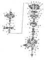
图1是本实施例电动三轮车上的圆柱体变速器连接差速器的外观图;1 is an external view of a cylindrical transmission connecting differential on an electric tricycle of the embodiment;
图2是本实施例有超越离合器的电动三轮车上的圆柱体变速器连接差速器的部件图;2 is a view showing the components of a cylindrical transmission connection differential on an electric tricycle having an overrunning clutch according to the present embodiment;
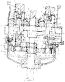
图3是本实施例设有超越离合器的应用在电动三轮车上的圆柱体变速器连接差速器的横切面图;3 is a cross-sectional view showing a cylindrical transmission connection differential applied to an electric tricycle provided with an overrunning clutch according to the embodiment;
图4是本实施例无超越离合器的应用在电动三轮车上的圆柱体变速器连接差速器的横切面图;4 is a cross-sectional view showing the cylindrical transmission connecting differential applied to the electric tricycle without the overrunning clutch of the embodiment;
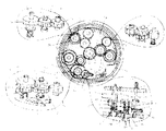
图5是本实施例电动三轮车上的变速器的主动齿轮与变速齿轮啮合的圆切面图;Figure 5 is a circular cross-sectional view showing the meshing of the driving gear and the shifting gear of the transmission on the electric tricycle of the embodiment;
图6是本实施例有超越离合器的电动三轮车上的圆柱体变速器连接差速器的纵切面图;Figure 6 is a longitudinal sectional view showing the cylindrical transmission connecting differential on the electric tricycle having the overrunning clutch of the embodiment;
图7是本实施例电动三轮车上的变速器的手动换挡装置示意图;Figure 7 is a schematic view of a manual shifting device of the transmission on the electric tricycle of the embodiment;
图8是本实施例无超越离合器的电动三轮车上的变速器连接差速器的横切面图;Figure 8 is a cross-sectional view showing the transmission connecting differential on the electric tricycle without the overrunning clutch of the embodiment;
图9是本实施例H字盘内平面上设置弹簧片的示意图;Figure 9 is a schematic view showing a spring piece disposed on a plane in the H-shaped disk of the embodiment;
图10是本实施例汽车变速器的齿轮啮合状况图;
Figure 10 is a gear meshing state diagram of the automobile transmission of the embodiment;
图11是本实施例设有超越离合器的汽车变速器连接差速器的结构切面图;Figure 11 is a cross-sectional view showing the structure of a vehicle transmission connecting differential provided with an overrunning clutch according to the embodiment;
图12是本实施例无超越离合器的汽车变速器连接差速器的切面图;Figure 12 is a cross-sectional view showing the automotive transmission connection differential without the overrunning clutch of the embodiment;
图13是本实施例自保持式电磁铁控制变速齿轮底轮升降的结构示意图;Figure 13 is a schematic structural view of the self-holding electromagnet controlling the bottom gear of the shifting gear according to the embodiment;
图14是本实施例自保持式电磁铁控制变速齿轮底轮升降的部件图;Figure 14 is a view showing the components of the self-holding electromagnet of the present embodiment for controlling the lifting and lowering of the shifting gear bottom wheel;
图15是本实施例汽车变速器的前进挡与倒挡设置的圆切面图;Figure 15 is a circular cross-sectional view showing the forward gear and the reverse gear of the automobile transmission of the embodiment;
图16是本实施例汽车变速器的倒挡设置的结构图;Figure 16 is a structural view showing a reverse gear setting of the automobile transmission of the embodiment;
图17是本实施例主动齿轮与输入轴活连接的示意图;Figure 17 is a schematic view showing the active gear and the input shaft in the present embodiment;
图18是本实施例主动齿轮与输入轴活连接的部件图;Figure 18 is a view showing the components of the active gear and the input shaft in the present embodiment;
图19是本实施例变速齿轮上轮与变速齿轮轴间活连接的示意图;Figure 19 is a schematic view showing the live connection between the upper wheel of the shifting gear and the shifting gear shaft of the present embodiment;
图20是本实施例变速齿轮底轮与变速齿轮轴活连接的示意图;Figure 20 is a schematic view showing the living connection of the shifting gear bottom wheel and the shifting gear shaft of the embodiment;
图21是本实施例有双拨板的变速齿轮上轮与变速齿轮轴活连接的示意图;Figure 21 is a schematic view showing the live connection of the upper gear of the shifting gear with the double-dial plate and the shifting gear shaft of the embodiment;
图22是本实施例旋转盘中心与输出轴活连接的结构切面图;Figure 22 is a cross-sectional view showing the structure of the center of the rotating disk and the output shaft in the present embodiment;
图23是本实施例旋转盘中心与输出轴活连接的部件图;Figure 23 is a view showing the components of the center of the rotary disk and the output shaft in the present embodiment;
图24是本实施例设置有中间齿轮、变速齿轮的示意图;Figure 24 is a schematic view showing the intermediate gear and the shifting gear provided in the embodiment;
图25是本实施例用按钮挡控制自保持式电磁铁、控制变速器换挡的示意图;Figure 25 is a schematic view showing the control of the shifting of the self-holding electromagnet and the control of the transmission by the button block in the embodiment;
图26是本实施例设置有中间齿轮、变速齿轮、倒挡齿轮的齿轮啮合状况的示意图;Figure 26 is a schematic view showing the meshing condition of the gear provided with the intermediate gear, the shifting gear, and the reverse gear in the embodiment;
图27是本实施例用舵机控制变速器换挡的结构切面图;Figure 27 is a cross-sectional view showing the structure of the shifting of the transmission by the steering gear of the embodiment;
图28是本实施例用舵机控制变速器换挡的部件图;Figure 28 is a view showing the components for controlling the shifting of the transmission by the steering gear according to the embodiment;
图29是本实施例用舵机控制变速器换挡的舵机及控制按钮图;Figure 29 is a diagram showing the steering gear and the control button for controlling the transmission shift by the steering gear according to the embodiment;
图30是本实施例用舵机控制变速器换挡的换挡方式示意图;Figure 30 is a schematic view showing the shifting mode of the shifting of the transmission by the steering gear of the embodiment;
图31是本实施例用舵机控制换挡的自动挡变速器结构切面图;
Figure 31 is a cross-sectional view showing the structure of the automatic transmission which is controlled by the steering gear of the present embodiment;
图32是本实施例电动二轮车的后驱变速器的结构切面图;Figure 32 is a cross-sectional view showing the structure of a rear-drive transmission of the electric two-wheeled vehicle of the present embodiment;
图33是本实施例有固定平盘的变速器的圆切面图;Figure 33 is a circular cross-sectional view of the transmission having the fixed flat plate of the embodiment;
图34是本实施例电动二轮车上的后驱变速器上设置链轮的切面图;Figure 34 is a cross-sectional view showing a sprocket provided on a rear-drive transmission on the electric two-wheeled vehicle of the embodiment;
图35是本实施例设置四挡变速器的圆切面图;Figure 35 is a cross-sectional view showing the fourth speed transmission of the embodiment;
图36是本实施例二轮自行车上后置变速器的圆切面图;Figure 36 is a cross-sectional view showing the rear transmission of the two-wheeled bicycle of the embodiment;
图37是本实施例二轮自行车上后置变速器的结构切面图;Figure 37 is a cross-sectional view showing the structure of the rear-wheel drive on the two-wheeled bicycle of the embodiment;
图38是本实施例设有超越离合器的后驱电动汽车变速器结构切面图;Figure 38 is a cross-sectional view showing the structure of a rear-drive electric vehicle transmission provided with an overrunning clutch according to the embodiment;
图39是本实施例无超越离合器的电动汽车后驱变速器结构切面图;39 is a cross-sectional view showing the structure of a rear-drive transmission of an electric vehicle without an overrunning clutch according to the embodiment;
图40是本实施例自保持式电磁铁控制变速器换挡的结构示意图;40 is a schematic structural view showing the shifting of the transmission by the self-holding electromagnet according to the embodiment;
图41是本实施例若干个舵机分别控制变速器换挡的示意图;Figure 41 is a schematic view showing a plurality of steering gears respectively controlling the shifting of the transmission in the embodiment;
图42是本实施例由拨叉控制换挡的设有多个变速齿轮上轮的变速器结构切面图;Figure 42 is a cross-sectional view showing the transmission structure of the upper wheel provided with a plurality of shifting gears controlled by the fork control in the present embodiment;
图43是本实施例设有多个变速齿轮上轮的变速器圆切面图;Figure 43 is a cross-sectional view of the transmission in which the upper wheels of the plurality of shifting gears are provided in the embodiment;
图44是本实施例设有多个变速齿轮上轮的换挡方式图;Figure 44 is a diagram showing the shifting mode in which the upper wheels of the plurality of shifting gears are provided in the embodiment;
图45是本实施例设有中间齿轮的变速器的结构切面图;Figure 45 is a cross-sectional view showing the structure of a transmission provided with an intermediate gear of the embodiment;
图46是本实施例设有中间齿轮的变速器的圆切面图;Figure 46 is a circular cross-sectional view of the transmission provided with the intermediate gear of the embodiment;
图47是本实施例设置槽轮换挡的结构切面图;Figure 47 is a cross-sectional view showing the structure of the shifting of the sheave of the embodiment;
图48是本实施例发动机与变速器间设置电磁自动离合器的示意图;Figure 48 is a schematic view showing the arrangement of an electromagnetic automatic clutch between the engine and the transmission in the embodiment;
图49是本实施例设置槽轮换挡的部件图;Figure 49 is a view showing the components of the shifting gear of the embodiment;
图50是本实施例发动机与变速器间设置机械式自动离合器的示意图;Figure 50 is a schematic view showing the mechanical automatic clutch disposed between the engine and the transmission in the embodiment;
图51是本实施例在变速器前端盖中心上面设置舵机的结构图。Figure 51 is a structural view showing the provision of a steering gear on the center of the front end cover of the transmission in this embodiment.
附图标记:
Reference mark:
1-油封;2-变速器前端盖;3-前端盖凸圆;4-孔用弹性挡圈;5-轴承;6-输入轴;7-外花键;8-键槽;9-拨挡套轮;10-挡位压板;11-斜面;12-双联中间拨挡轮;13-外侧拨挡齿轮;14-外侧拨挡齿轮轴;15-隔离圈;16-H字盘;17-H字盘内平面;18-变速器中心孔;19-H字盘凸圆;20-固体镶嵌轴承;21-油底壳;22-加油阀;23-放油阀;24-油平面阀;25-主动齿轮;26-变速齿轮上轮;27-变速齿轮底轮;28-轴用弹性挡圈;29-固定盘;30-固定盘侧开口;31-弹簧片圈;32-旋转盘;33-旋转盘内齿;34-待啮合外齿;35-超越离合器;36-压缩弹簧;37-分合盘;38-待啮合内齿;39-销轴;40-键;41-输出轴;42-输出齿轮;43-变速器后壳;44-差速器壳;45-差速器内侧面;46-差速器外侧面;47-差速器介轮孔;48-差速包;49-从动齿轮;50-油封端盖;51-钢珠;52-顶杆;53-自保持式电磁铁;54-挡位拉板;55-电机;56-电机轴;57-内花键;58-电机前端盖;59-螺杆;60-密封垫;61-变速齿轮轴;62-固定盘内平面;63-柱头;64-介齿轮;65-介齿轮轴;66-电磁铁推拉杆;67-定位销;68-弹簧片;69-边口;70-变速单齿轮;71-螺母;72-止口;73-换挡中间齿轮轴;74-换挡拉板;75-换挡拉线;76-换挡器盒;77-换挡把;78-挡位轨道槽;79-球头螺丝;80-平垫圈;81-电子自动控制器;82-燕尾螺丝;83-电流传感器;84-扭矩传感器;85-转数传感器;86-电线;87-结合凸缘;88-结合凹槽;89-轴孔;90-横向扁孔;91-电磁铁底座;92-电磁铁连接器;93-横向孔;94-丝扣;95-翘翘板架;96-拨叉;97-换挡叉杆;98-顶丝;99-倒挡齿轮轴;100-倒挡齿轮;101-翘翘板;102-拨板;103-凹槽;104-挡圈沟槽;105-挡位按钮盘;106-中间齿轮上轮;107-中间齿轮底轮;108-中间单齿轮;109-中间齿轮轴;110-内花键轴套;111-圆台;112-舵机;113-外挡边铜套;114-变速器后端盖;115-挡位按钮;116-延伸套;117-驱动轴管;118-内花键套圈;119-
轴承窝;120-挡位显示屏;121-固定平盘;122-轮毂盘;123-左侧连接盘;124-减震器爪;125-车底叉爪;126-输入轴管连接圈;127-盘式刹车;128-刹车蹄;129-右侧连接盘;130-固定柱;131-轮胎;132-减震器;133-车底叉;134-链轮;135-输入轴管;136-自行车后轴;137-O型油封;138-输出轴管;139-槽轮;140-止推垫;141-抱闸式刹车;142-顶杆限位板;143-滚针轴承;144-同步器;145-内丝扣管;146-拨挡中间单齿轮;147-油丝;148-软线端头(外缘有丝扣);149-软线;150-油丝柱头;151-燃油发动机;152-发动机输出轴;153-电磁自动离合器;154-柱头驳接孔;155-槽轮连接管;156-机械式自动离合器;157-铜垫圈;159-卡口。1-oil seal; 2-transmission front end cover; 3- front end cover convex; 4-hole circlip; 5-bearing; 6-input shaft; 7-outer spline; 8--keyway; ;10-position pressure plate; 11-bevel; 12-double intermediate shift wheel; 13-outer shift gear; 14-outer shift gear shaft; 15-isosphere; 16-H dial; 17-H In-plane plane; 18-transmission center hole; 19-H dial convex; 20-solid inlaid bearing; 21-oil sump; 22-refueling valve; 23-drain valve; 24-oil plane valve; Gear; 26-speed gear upper wheel; 27-speed gear bottom wheel; 28-axis circlip; 29-fixed disk; 30-fixed disk side opening; 31-spring ring; 32-rotary disk; In-disk tooth; 34-to-be-engaged external tooth; 35-overrunning clutch; 36-compression spring; 37-distribution disk; 38-to-be-engaged internal tooth; 39-pin shaft; 40-key; 41-output shaft; Output gear; 43-transmission rear case; 44- differential case; 45- differential inner side; 46-differential outer side; 47-differential wheel hole; 48-differential package; Moving gear; 50-oil seal end cover; 51-steel ball; 52-rod; 53-self-holding electromagnet; 54-stop pull plate; 55- Machine; 56-motor shaft; 57-internal spline; 58-motor front end cover; 59-screw; 60-seal; 61-transmission gear shaft; 62-fixed disc inner plane; 63-column head; 64-spindle gear; 65-media gear shaft; 66-electromagnet push-pull rod; 67-positioning pin; 68-spring piece; 69-side port; 70-speed single gear; 71-nut; 72-stop; 73-shift intermediate gear shaft ;74-Shifting pull plate; 75-shift cable; 76-shifter box; 77-shift lever; 78-gear track slot; 79-ball head screw; 80-flat washer; 81-electronic automatic control 82- dovetail screw; 83-current sensor; 84-torque sensor; 85-rev. sensor; 86-wire; 87-bonded flange; 88-bonded groove; 89-shaft hole; 90-transverse flat hole; 91-electromagnet base; 92-electromagnet connector; 93-transverse hole; 94-threaded; 95-wobbled frame; 96-spoke; 97-shift fork; 98-top wire; Geared shaft; 100-reverse gear; 101-warp plate; 102-dial; 103-groove; 104-stop groove; 105-gear button plate; 106-intermediate gear upper wheel; Gear bottom wheel; 108-intermediate single gear; 109-intermediate gear shaft; 110-internal spline bushing; 111- Station; 112- steering gear; 113- copper sleeve outer wall; 114- after the transmission cover; 115- button gear; 116- extending sleeve; 117- driveshaft tube; 118- splined inner ferrule; 119-
Bearing socket; 120-gear display; 121-fixed flat plate; 122-wheel hub; 123-left side lands; 124-damper jaws; 125-vehicle forks; 126-input shaft tube connection ring; 127-disc brake; 128-brake shoe; 129-right connection plate; 130-fixed column; 131-tire; 132-shock absorber; 133-car fork; 134-sprocket; 135-input shaft tube; 136-bicycle rear axle; 137-O oil seal; 138-output shaft tube; 139-groove wheel; 140- thrust pad; 141-brake brake; 142-rod limit plate; 143-needle bearing; 144-synchronizer; 145-inner threaded tube; 146-shift intermediate single gear; 147-oil thread; 148- cord end (threaded outer edge); 149- cord; 150-oil head; 151-fuel engine; 152-engine output shaft; 153-electromagnetic automatic clutch; 154-column docking hole; 155-groove connecting tube; 156-mechanical automatic clutch; 157-copper washer; 159-bayonet.
下面结合附图和实施例,对本发明技术方案作进一步描述。The technical solutions of the present invention are further described below in conjunction with the accompanying drawings and embodiments.
实施例1Example 1
参见图10、图11、图12、图13、图14、图38和图39,本实施例的圆柱体变速器包括壳体、输入轴6和输出轴41。壳体包括若干个圆盘,圆盘设置有外边口69,输入轴6和输出轴41设置在若干个圆盘的中心线上,输入轴6上有若干个主动齿轮25,输出轴41上有旋转盘32,旋转盘32上有旋转盘内齿33。在两个相邻的圆盘间有若干颗齿轮轴,齿轮轴位于两个相邻的圆盘间的主动齿轮25的外围,齿轮轴上有若干个齿轮。齿轮与旋转盘32相邻,且若干个齿轮中的一个齿轮与旋转盘内齿33分离或啮合。各圆盘通过外边口69相互连接。在具体应用中,虽然圆柱体变速器有凸圆、油底壳等,不完全构成圆面,但是它们之间存在着完全相同的圆面和止口。本实施例将符合这种特征的盘统称为
圆柱体变速器的圆盘。Referring to Figures 10, 11, 12, 13, 14, 38 and 39, the cylindrical transmission of the present embodiment includes a housing, an input shaft 6 and an output shaft 41. The housing comprises a plurality of discs, the disc is provided with an outer edge 69, the input shaft 6 and the output shaft 41 are arranged on the center line of a plurality of discs, and the input shaft 6 has a plurality of driving gears 25, and the output shaft 41 has The rotary disk 32 has a rotating disk inner tooth 33 thereon. There are a plurality of gear shafts between two adjacent discs. The gear shaft is located at the periphery of the driving gear 25 between two adjacent discs, and the gear shaft has a plurality of gears. The gear is adjacent to the rotating disk 32, and one of the plurality of gears is separated or meshed with the rotating disk inner teeth 33. The discs are connected to each other by an outer port 69. In the specific application, although the cylindrical transmission has a convex circle, an oil pan and the like, and does not completely constitute a circular surface, there are exactly the same circular faces and stops between them. This embodiment refers to a disk that conforms to this feature.
The disc of the cylinder transmission.
圆柱体变速器的壳体上有加油阀22、油平面阀24、油底壳21,油底壳上有放油阀23;各圆盘边口间有止口72、密封垫60、定位销67;螺杆59、螺母71连接各外边口69。上述特征是圆柱体变速器共同的特征,在后面的实施例中不再赘述。The casing of the cylinder transmission has a filling valve 22, an oil level valve 24, an oil pan 21, and an oil drain valve 23 on the oil pan; a port 72, a gasket 60 and a positioning pin 67 between the disc edges. The screw 59 and the nut 71 are connected to the outer edges 69. The above features are common features of the cylindrical transmission and will not be described again in the following embodiments.
本实施例圆柱体变速器的若干个圆盘包括H字盘16、固定盘29和变速器后端盖114。固定盘29上有固定盘侧开口30。齿轮轴包括变速齿轮轴61,齿轮包括变速齿轮上轮26和变速齿轮底轮27。若干个主动齿轮25固定在H字盘16与固定盘29间的输入轴6上,固定盘内平面62设置于旋转盘内齿33下方。H字盘16一侧与固定盘29和变速器后端盖114连接。H字盘16中心有轴承5和油封1。固定盘29中心有两个轴承5。输入轴6的一端穿入固定盘29中心的轴承5,输入轴6的另一端穿过H字盘16中心的轴承5和油封1。H字盘内平面17与固定盘内平面62上有若干个相对应的轴承窝119,轴承窝119内有轴承5。变速齿轮轴61两端分别插入轴承窝119内的轴承5。变速齿轮上轮26固定在变速齿轮轴61上,变速齿轮底轮内有内花键57,变速齿轮轴上有外花键7,变速齿轮底轮27通过花键与变速齿轮轴61套接。若干个主动齿轮25分别与变速齿轮上轮26啮合。变速齿轮底轮27的下方有压缩弹簧36。变速齿轮底轮27与旋转盘内齿33相邻并保持间隙,变速齿轮底轮27与旋转盘内齿33分离或啮合。变速器后端盖114设置在旋转盘32的外侧。The plurality of disks of the cylindrical transmission of the present embodiment include an H-shaped disk 16, a fixed disk 29, and a transmission rear end cover 114. The fixed disk 29 has a fixed disk side opening 30. The gear shaft includes a shifting gear shaft 61, and the gear includes a shifting gear upper wheel 26 and a shifting gear bottom wheel 27. A plurality of driving gears 25 are fixed to the input shaft 6 between the H-shaped disk 16 and the fixed disk 29, and the fixed disk inner surface 62 is disposed below the rotating disk inner teeth 33. The H-shaped disk 16 side is connected to the fixed disk 29 and the transmission rear end cover 114. The center of the H-shaped disk 16 has a bearing 5 and an oil seal 1. There are two bearings 5 in the center of the fixed disk 29. One end of the input shaft 6 penetrates the bearing 5 at the center of the fixed disk 29, and the other end of the input shaft 6 passes through the bearing 5 at the center of the H-shaped disk 16 and the oil seal 1. The inner surface 17 of the H-shaped disk and the inner surface 62 of the fixed disk have a plurality of corresponding bearing sockets 119, and the bearing housing 119 has bearings 5 therein. Both ends of the shift gear shaft 61 are inserted into the bearings 5 in the bearing housing 119, respectively. The shift gear upper wheel 26 is fixed to the shift gear shaft 61. The shift gear bottom wheel has an internal spline 57. The shift gear shaft has an external spline 7, and the shift gear bottom wheel 27 is sleeved with the shift gear shaft 61 via a spline. A plurality of driving gears 25 mesh with the shifting gear upper wheel 26, respectively. Below the shifting gear bottom wheel 27 is a compression spring 36. The shifting gear bottom wheel 27 is adjacent to the rotating disc inner teeth 33 and maintains a gap, and the shifting gear bottom wheel 27 is separated or meshed with the rotating disc inner teeth 33. The transmission rear end cover 114 is disposed outside the rotary disk 32.
参见图11、图12、图13、图14、图38和图39,H字盘内平面17上设置有若干个自保持式电磁铁53、电磁铁底座91和电磁铁连接器92。自保持式电磁铁53固定在电磁铁底座91上。自保持式电磁铁53内设置有电磁铁推拉杆66。
电磁铁推拉杆66穿过电磁铁底座91上的油封1,并且与电磁铁连接器92连接,电磁铁推拉杆上有丝扣94,电磁铁连接器顶面上有丝扣94。变速齿轮轴61内有轴孔89和顶杆52。顶杆52的顶端设置有铜垫圈157、轴用弹性挡圈28和钢珠51,顶杆52的下端穿入轴孔89。电磁铁连接器92底侧有卡口159,卡口159插在铜垫圈157的底侧。变速齿轮轴61上有横向扁孔90。变速齿轮底轮27、变速齿轮轴61和顶杆52通过燕尾螺丝82在横向扁孔90内连接在一起,燕尾螺丝穿过变速齿轮底轮和变速齿轮轴,旋紧在变速齿轮底轮另一侧的丝扣中。Referring to Fig. 11, Fig. 12, Fig. 13, Fig. 14, Fig. 38 and Fig. 39, a plurality of self-retaining electromagnets 53, an electromagnet base 91 and an electromagnet connector 92 are disposed on the plane 17 of the H-disk. The self-holding electromagnet 53 is fixed to the electromagnet base 91. An electromagnet push-pull rod 66 is provided in the self-holding electromagnet 53.
The electromagnet push-pull rod 66 passes through the oil seal 1 on the electromagnet base 91 and is connected to the electromagnet connector 92. The electromagnet push-pull rod has a threaded fastener 94 on the top surface of the electromagnet connector. The shift gear shaft 61 has a shaft hole 89 and a ram 52 therein. The top end of the jack 52 is provided with a copper washer 157, a shaft yoke 28 and a steel ball 51, and the lower end of the jack 52 penetrates the shaft hole 89. The electromagnet connector 92 has a bayonet 159 on the bottom side, and the bayonet 159 is inserted in the bottom side of the copper washer 157. The shift gear shaft 61 has a transverse flat hole 90 therein. The shifting gear bottom wheel 27, the shifting gear shaft 61 and the ejector pin 52 are connected together in the transverse flat hole 90 by the dovetail screw 82, and the dovetail screw passes through the shifting gear bottom wheel and the shifting gear shaft, and is screwed to the shifting gear bottom wheel and the other In the side of the thread.
或者,参见图40,H字盘内平面17上设置有若干个自保持式电磁铁53。自保持式电磁铁53内设置有电磁铁推拉杆66。变速齿轮轴61内有轴孔89,轴孔89内设置有顶杆52和钢珠51。电磁铁推拉杆66插入轴孔89内。变速齿轮轴61上有横向扁孔90,横向扁孔90内设置有销轴39,销轴39位于变速齿轮底轮27的上方,变速齿轮底轮下方有弹簧片圈31。Alternatively, referring to Fig. 40, a plurality of self-holding electromagnets 53 are disposed on the plane 17 of the H-shaped disk. An electromagnet push-pull rod 66 is provided in the self-holding electromagnet 53. The shift gear shaft 61 has a shaft hole 89 therein, and the shaft hole 89 is provided with a jack 52 and a steel ball 51. The electromagnet push-pull rod 66 is inserted into the shaft hole 89. The shifting gear shaft 61 has a transverse flat hole 90. The horizontal flat hole 90 is provided with a pin 39. The pin 39 is located above the shifting gear bottom wheel 27, and a spring ring 31 is disposed below the shifting gear bottom wheel.
参见图11,输出轴41的顶端穿入固定盘29中心的轴承5,输出轴41外缘和旋转盘32中心间有轴承5和超越离合器35。超越离合器35一侧的输出轴41上有压缩弹簧36和分合盘37。输出轴41的底端有输出齿轮42。输出轴41的底端中心内有钢珠51和顶杆52。变速器后端盖114上有油封端盖50,油封端盖50上有自保持式电磁铁53。输出轴上有外花键7,分合盘内有内花键57,分合盘37通过花键与输出轴41套接。输出轴41上设置有横向扁孔90,分合盘37的顶端设置有与横向扁孔90相配合的销轴39。旋转盘一侧有结合凸缘87,分合盘上有结合凹槽88,分合盘37与旋转盘32中心一侧分离或咬合。Referring to Fig. 11, the top end of the output shaft 41 penetrates the bearing 5 at the center of the fixed disk 29, and the outer periphery of the output shaft 41 and the center of the rotary disk 32 have a bearing 5 and an overrunning clutch 35. The output shaft 41 on the side of the overrunning clutch 35 has a compression spring 36 and a splitter disk 37. The output shaft 41 has an output gear 42 at its bottom end. The center of the bottom end of the output shaft 41 has a steel ball 51 and a ram 52 therein. The transmission rear end cover 114 has an oil seal end cover 50, and the oil seal end cover 50 has a self-holding electromagnet 53 thereon. The output shaft has an external spline 7 with an internal spline 57 therein, and the splitter disc 37 is sleeved with the output shaft 41 via a spline. The output shaft 41 is provided with a lateral flat hole 90, and the top end of the splitter disk 37 is provided with a pin 39 that cooperates with the lateral flat hole 90. On one side of the rotating disc, there is a coupling flange 87, and the separating disc has a coupling groove 88, and the separating disc 37 is separated or engaged with the center side of the rotating disc 32.
参见图12,旋转盘32中心固定在输出轴41上,输出轴41的顶端穿入固定盘29中心的轴承5,输出轴41的底端有输出齿轮42,输出轴41的底端穿入变
速器后端盖114的轴承5。变速器后端上有油封端盖50。Referring to Fig. 12, the center of the rotary disk 32 is fixed to the output shaft 41. The top end of the output shaft 41 penetrates the bearing 5 at the center of the fixed disk 29. The bottom end of the output shaft 41 has an output gear 42, and the bottom end of the output shaft 41 is inserted.
The bearing 5 of the rear end cover 114 of the speeder. An oil seal end cap 50 is provided on the rear end of the transmission.
参见图38,输出轴41的顶端穿入固定盘29中心的轴承5,输出轴41外缘和旋转盘32中心间有轴承5和超越离合器35。超越离合器35一侧的输出轴41上有分合盘37。分合盘37通过花键与输出轴41套接。分合盘37与旋转盘32中心一侧分离或咬合。输出轴41的底端穿过变速器后端盖114的轴承5和油封1。变速器后端盖114内壁上有顶杆限位板142、顶杆52和拨叉96,拨叉96插在分合盘37上设置的凹槽103外缘。顶杆52外缘上有压缩弹簧36,顶杆52底端的变速器后端盖114上有自保持式电磁铁53。顶杆52穿过变速器后端盖114和顶杆限位板142上的孔。Referring to Fig. 38, the top end of the output shaft 41 penetrates the bearing 5 at the center of the fixed disk 29, and the outer periphery of the output shaft 41 and the center of the rotary disk 32 have a bearing 5 and an overrunning clutch 35. The output shaft 41 on the side of the overrunning clutch 35 has a splitter disk 37. The split disk 37 is sleeved with the output shaft 41 by splines. The split disk 37 is separated or engaged from the center side of the rotary disk 32. The bottom end of the output shaft 41 passes through the bearing 5 of the transmission rear end cover 114 and the oil seal 1. The inner wall of the rear end cover 114 of the transmission has a top rod limiting plate 142, a top rod 52 and a shifting fork 96. The shifting fork 96 is inserted into the outer edge of the groove 103 provided on the splitter disc 37. A compression spring 36 is disposed on the outer edge of the jack 52, and a self-retaining electromagnet 53 is disposed on the transmission rear end cover 114 at the bottom end of the jack 52. The jack 52 passes through a hole in the transmission rear end cover 114 and the jack stop plate 142.
参见图24,齿轮轴还包括中间齿轮轴109。齿轮还包括中间齿轮上轮106和中间齿轮底轮107。主动齿轮25固定在H字盘内平面17与固定盘29间的输入轴6上。主动齿轮25与中间齿轮上轮106或中间齿轮底轮107啮合,中间齿轮上轮106或中间齿轮底轮107与变速齿轮上轮26啮合。Referring to Figure 24, the gear shaft also includes an intermediate gear shaft 109. The gear also includes an intermediate gear upper wheel 106 and an intermediate gear bottom wheel 107. The driving gear 25 is fixed to the input shaft 6 between the flat surface 17 of the H-shaped disk and the fixed disk 29. The drive gear 25 meshes with the intermediate gear upper wheel 106 or the intermediate gear bottom wheel 107, and the intermediate gear upper wheel 106 or the intermediate gear bottom wheel 107 meshes with the shift gear upper wheel 26.
参见图15、图16和图26,齿轮还包括倒挡齿轮100。变速齿轮底轮27与倒挡齿轮100设置在旋转盘内齿33上方,变速齿轮底轮27与旋转盘内齿33分离或啮合。倒挡齿轮100与变速齿轮底轮27啮合。倒挡齿轮100通过倒挡齿轮轴99固定在固定盘内平面62上。倒挡齿轮轴99外缘有压缩弹簧36,倒挡齿轮轴99的顶端有平垫圈80和轴用弹性挡圈28。压缩弹簧36的下方有翘翘板101。倒挡齿轮100的中心有外挡边铜套113,倒挡齿轮轴99上有固体镶嵌轴承20。倒挡齿轮100的一侧设置有换挡控制装置,换挡控制装置包括换挡叉杆97和第一拨叉96。换挡叉杆97设置在H字盘内平面17和固定盘内平面62之间,且穿过H字盘内平面17。第一拨叉96固定在换挡叉杆97上,且插入设置在倒挡
齿轮100的顶端上的凹槽103外缘。倒挡齿轮100与旋转盘内齿33分离或者啮合。Referring to Figures 15, 16 and 26, the gear further includes a reverse gear 100. The shifting gear bottom wheel 27 and the reverse gear 100 are disposed above the rotating disk inner teeth 33, and the shifting gear bottom wheel 27 is separated or meshed with the rotating disk inner teeth 33. The reverse gear 100 meshes with the shift gear bottom wheel 27. The reverse gear 100 is fixed to the fixed disk inner plane 62 by a reverse gear shaft 99. The outer edge of the reverse gear shaft 99 has a compression spring 36, and the top end of the reverse gear shaft 99 has a flat washer 80 and a shaft circlip 28. Below the compression spring 36 is a seesaw 101. The center of the reverse gear 100 has an outer rib bushing 113, and the reverse gear shaft 99 has a solid inlaid bearing 20. One side of the reverse gear 100 is provided with a shift control device, and the shift control device includes a shift fork 97 and a first shift fork 96. The shift fork lever 97 is disposed between the H-disc inner plane 17 and the fixed disc inner plane 62 and passes through the H-disk inner plane 17. The first fork 96 is fixed to the shift fork 97 and is inserted in the reverse gear
The outer edge of the groove 103 on the top end of the gear 100. The reverse gear 100 is disengaged or meshed with the inner teeth 33 of the rotary disk.
参见图42和图43,两个相邻的变速齿轮上轮26间有同步器144,同步器144通过花键与变速齿轮轴61套接,同步器上有内花键57,变速齿轮轴上有外花键7。同步器上设置有待啮合内齿38,变速齿轮上轮26上设置有与待啮合内齿38相配合的待啮合外齿34。变速齿轮底轮27固定在变速齿轮轴61上,并且与旋转盘内齿33啮合。若干个变速齿轮上轮26与变速齿轮轴61间有滚针轴承143。换挡装置还包括第二拨叉96,第二拨叉96插入设置在变速齿轮轴61上的同步器144的凹槽103外缘。Referring to Figures 42 and 43, a synchronizer 144 is disposed between the two adjacent shifting gear upper wheels 26, and the synchronizer 144 is sleeved with the shifting gear shaft 61 via a spline having an internal spline 57 on the shifting gear shaft. There are external splines 7. The synchronizer is provided with internal teeth 38 to be engaged, and the upper gear wheel 26 is provided with external teeth 34 to be engaged with the internal teeth 38 to be engaged. The shifting gear bottom wheel 27 is fixed to the shifting gear shaft 61 and meshes with the rotating disc inner teeth 33. A needle bearing 143 is provided between the plurality of shifting gear upper wheels 26 and the shifting gear shaft 61. The shifting device further includes a second shift fork 96 that is inserted into the outer edge of the recess 103 of the synchronizer 144 disposed on the shifting gear shaft 61.
参见图11、图12、图25、图38、图39和图41,本实施例的圆柱体变速器的自动挡控制装置的结构包括:H字盘内平面17上有若干个自保持式电磁铁53,自保持式电磁铁53有电线86连接电子自动控制器81,变速器后端盖114的旋转盘32外围上有扭矩传感器84和转数传感器85,电机55上有电量传感器。扭矩传感器84、转数传感器85、电流传感器83有电线86连接电子自动控制器81,电子自动控制器内可以设置换挡传感器。Referring to FIG. 11, FIG. 12, FIG. 25, FIG. 38, FIG. 39 and FIG. 41, the structure of the automatic transmission control device for the cylindrical transmission of the present embodiment includes: a plurality of self-retaining electromagnets on the plane 17 of the H-shaped disk. The self-holding electromagnet 53 has a wire 86 connected to the electronic automatic controller 81. The periphery of the rotary disk 32 of the transmission rear end cover 114 has a torque sensor 84 and a revolution number sensor 85. The motor 55 has a charge sensor. The torque sensor 84, the revolution number sensor 85, and the current sensor 83 have a wire 86 connected to the electronic automatic controller 81, and a shift sensor can be provided in the electronic automatic controller.
参见图32、图47和图51,主动齿轮25上有延伸套116,延伸套116内有内花键57。延伸套116穿过H字盘16中心的固体镶嵌轴承20,延伸套116的端头有轴用弹性挡圈28。输入轴6的端头有外花键7。输入轴6穿过外部驱动装置的驱动轴管117后再穿入H字盘16中心和延伸套116中。参见图17和图18,主动齿轮25的内圆有第一凹槽103,主动齿轮25内圆的输入轴6上有第一横向扁孔90,第一横向扁孔90内有第一拨板102。第一凹槽103套入第一拨板102外缘,主动齿轮25上侧有第一平垫圈80和第一轴用弹性挡圈28。参见图
19,变速齿轮上轮26内圆有第二凹槽103,变速齿轮上轮26内圆内的变速齿轮轴61上有第二横向扁孔90,第二横向扁孔90内有第二拨板102。第二凹槽103套入第二拨板102外缘,变速齿轮上轮26上侧有第二平垫圈80和第二轴用弹性挡圈28。参见图20,变速齿轮底轮27内圆有第三凹槽103,变速齿轮底轮27内圆中心的变速齿轮轴61上有第三横向扁孔90,第三横向扁孔90内有第三拨板102。第三凹槽103套入第三拨板102外缘,变速齿轮底轮27下侧有第三平垫圈80和第三轴用弹性挡圈28。参见图22和图23,旋转盘32中心内圆有第四凹槽103,旋转盘32中心的输出轴41上有第四横向扁孔90,第四横向扁孔90内有第四拨板102。第四凹槽103套入第四拨板102外缘,输出轴41上的旋转盘32内侧有第四平垫圈80和第四轴用弹性挡圈28。Referring to Figures 32, 47 and 51, the drive gear 25 has an extension sleeve 116 with internal splines 57 therein. The extension sleeve 116 passes through the solid inlaid bearing 20 at the center of the H-shaped disk 16, and the end of the extension sleeve 116 has a circlip for the shaft. The end of the input shaft 6 has an external spline 7. The input shaft 6 passes through the drive shaft tube 117 of the external drive and then penetrates into the center of the H-shaped disk 16 and the extension sleeve 116. Referring to FIGS. 17 and 18, the inner circumference of the driving gear 25 has a first groove 103. The input shaft 6 of the inner circumference of the driving gear 25 has a first lateral flat hole 90, and the first horizontal flat hole 90 has a first dial. 102. The first groove 103 is sleeved into the outer edge of the first dial 102, and the upper side of the driving gear 25 has a first flat washer 80 and a first shaft circlip 28 . See picture
19, the inner wheel of the shifting gear upper wheel 26 has a second groove 103, the shifting gear shaft 61 in the inner circle of the upper wheel of the shifting gear 26 has a second lateral flat hole 90, and the second lateral flat hole 90 has a second dial plate 102. The second groove 103 is fitted into the outer edge of the second dial 102. The upper side of the upper wheel 26 of the shifting gear has a second flat washer 80 and a second shaft circlip 28. Referring to Fig. 20, the shift gear bottom wheel 27 has a third recess 103 in the inner circumference thereof. The shift gear shaft 61 at the center of the inner circumference of the shift gear bottom wheel 27 has a third lateral flat hole 90, and the third transverse flat hole 90 has a third recess. Dial pad 102. The third groove 103 is fitted into the outer edge of the third dial 102, and the third flat washer 80 and the third shaft circlip 28 are provided on the lower side of the shift gear bottom wheel 27. Referring to Figures 22 and 23, the inner circumference of the rotary disk 32 has a fourth recess 103. The output shaft 41 at the center of the rotary disk 32 has a fourth lateral flat hole 90. The fourth lateral flat hole 90 has a fourth dial 102 therein. . The fourth groove 103 is fitted into the outer edge of the fourth dial 102, and the inner side of the rotary disk 32 on the output shaft 41 has a fourth flat washer 80 and a fourth shaft circlip 28.
或者,参见图21,变速齿轮上轮26内圆有第二凹槽103,变速齿轮上轮26内圆中心的变速齿轮轴61上有两个相对的第四拨板102,第二凹槽103套入两个第四拨板102外缘。变速齿轮上轮26上侧有第二平垫圈80和第二轴用弹性挡圈28。Alternatively, referring to Fig. 21, the upper wheel of the shifting gear 26 has a second groove 103 therein, and the shifting gear shaft 61 at the center of the inner circumference of the upper wheel of the shifting gear 26 has two opposite fourth dials 102, and the second groove 103 The outer edges of the two fourth dials 102 are nested. The upper side of the shifting gear upper wheel 26 has a second flat washer 80 and a second shaft circlip 28 .
参见图12、图31、图39和图45,输出轴41的一端穿入固定盘29中心的轴承5,输出轴41的另一端穿过变速器后端盖114中的轴承5和油封1。旋转盘32中心固定在输出轴41上。Referring to Figures 12, 31, 39 and 45, one end of the output shaft 41 penetrates the bearing 5 at the center of the fixed disk 29, and the other end of the output shaft 41 passes through the bearing 5 and the oil seal 1 in the rear end cover 114 of the transmission. The center of the rotary disk 32 is fixed to the output shaft 41.
本实施例的圆柱体变速器,可以简单地实现自动挡控制,电子自动控制器根据各传感器输出的数据控制不同的自保持式电磁铁,控制变速齿轮底轮与旋转盘内齿分离或者啮合,实现自动换挡。相比于现有其他自动挡变速箱,具有体积小、造价低及简单易行等优点,避免了双离合变速器的复杂和繁琐,以及避免了液压自动变速箱的油耗过高。液压自动变速器、双离合变速器、无极变
速器很难和电动汽车的电机配置,而本实施例的圆柱体变速器由于其本身属于圆柱体,具有体积小、速度差大和造价低特点,因此能和电机形成良好的配置,产生出一种性价比高的全新的自动挡变速器。In the cylindrical transmission of the embodiment, the automatic gear control can be simply realized, and the electronic automatic controller controls different self-holding electromagnets according to the data output by the sensors, and controls the separation of the bottom gear of the shifting gear and the teeth of the rotating disk to realize the separation. Automatic shifting. Compared with other existing automatic transmissions, it has the advantages of small size, low cost and simple operation, which avoids the complexity and cumbersome of the dual clutch transmission and avoids the excessive fuel consumption of the hydraulic automatic transmission. Hydraulic automatic transmission, dual clutch transmission, stepless change
The speed converter is difficult to configure with the electric motor of the electric vehicle, and the cylindrical transmission of the present embodiment has a small size, a large speed difference, and a low cost because of its own cylindrical shape, so that it can form a good configuration with the motor, resulting in a kind of A new, cost-effective automatic transmission.
实施例2Example 2
参见图1、图2、图3、图4、图5、图6和图8,本实施例圆柱体变速器的若干个圆盘包括变速器前端盖2、H字盘16、固定盘29和变速器后壳43。变速器后壳43与差速器壳44构成一体化结构。其中相邻的两个圆盘为H字盘16和固定盘29,固定盘29上有固定盘侧开口30,固定盘内平面62设置于旋转盘内齿33下方。齿轮轴包括变速齿轮轴61。齿轮包括变速齿轮上轮26和变速齿轮底轮27,或者齿轮为变速单齿轮70。输入轴6的一端穿过变速器前端盖2中心的轴承5和油封1,输入轴6的另一端穿过H字盘16中心的轴承5。主动齿轮25固定在H字盘16和固定盘29间的输入轴6的端头。H字盘内平面17与固定盘内平面62上有若干个相对应的轴承窝119,轴承窝119内有固体镶嵌轴承20。变速齿轮上轮26和变速齿轮底轮27固定在H字盘16和固定盘29间的变速齿轮轴61上。变速齿轮轴61在变速器前端盖2下方,并且变速齿轮轴61顶端中心有钢珠51。变速齿轮轴61的顶端穿过H字盘内平面17内的固体镶嵌轴承20,变速齿轮轴61的底端穿入固定盘内平面62内的固体镶嵌轴承20,固定盘内平面62底面上有弹簧片圈31,变速齿轮轴61底端的轴心内有钢珠51和柱头63。变速齿轮底轮27与旋转盘内齿33相邻并保持间隙。主动齿轮25与变速齿轮上轮26啮合。变速齿轮底轮27与旋转盘内齿33分离或者啮合。H字盘16一侧连接变速器前端盖2,H字盘16另一侧与固定盘29和变速器后壳43连接。Referring to FIG. 1 , FIG. 2 , FIG. 3 , FIG. 4 , FIG. 5 , FIG. 6 and FIG. 8 , several discs of the cylindrical transmission of the embodiment include a transmission front end cover 2 , an H-shaped disk 16 , a fixed disk 29 , and a transmission. Shell 43. The transmission rear case 43 and the differential case 44 constitute an integrated structure. The two adjacent discs are an H-shaped disc 16 and a fixed disc 29, and the fixed disc 29 has a fixed disc side opening 30, and the fixed disc inner plane 62 is disposed below the rotating disc inner teeth 33. The gear shaft includes a shifting gear shaft 61. The gear includes a shifting gear upper wheel 26 and a shifting gear bottom wheel 27, or the gear is a shifting single gear 70. One end of the input shaft 6 passes through the bearing 5 at the center of the front end cover 2 of the transmission and the oil seal 1, and the other end of the input shaft 6 passes through the bearing 5 at the center of the H-shaped disk 16. The drive gear 25 is fixed to the end of the input shaft 6 between the H-shaped disk 16 and the fixed disk 29. The inner surface 17 of the H-shaped disk and the inner surface 62 of the fixed disk have a plurality of corresponding bearing sockets 119, and the bearing socket 119 has a solid inlaid bearing 20 therein. The shift gear upper wheel 26 and the shift gear bottom wheel 27 are fixed to the shift gear shaft 61 between the H-shaped disk 16 and the fixed disk 29. The shift gear shaft 61 is below the transmission front end cover 2, and the center of the top end of the shift gear shaft 61 has a steel ball 51. The top end of the shifting gear shaft 61 passes through the solid inlaid bearing 20 in the plane 17 of the H-shaped disc. The bottom end of the shifting gear shaft 61 penetrates into the solid inlaid bearing 20 in the plane 62 of the fixed disc, and the bottom surface of the flat surface 62 of the fixed disc has The spring coil 31 has a steel ball 51 and a column head 63 in the axial center of the bottom end of the transmission gear shaft 61. The shifting gear bottom wheel 27 is adjacent to the rotating disc inner teeth 33 and maintains a gap. The drive gear 25 meshes with the shift gear upper wheel 26. The shifting gear bottom wheel 27 is disengaged or meshed with the rotating disc inner teeth 33. The H-shaped disk 16 is connected to the transmission front end cover 2 on one side, and the other side of the H-shaped disk 16 is connected to the fixed disk 29 and the transmission rear case 43.
参见图2和图3,输出轴41的顶端穿入固定盘29中心的轴承5,输出轴41
外缘和旋转盘32中心间有轴承5和超越离合器35。超越离合器35一侧的输出轴41上有压缩弹簧36和分合盘37。输出轴41的底端有输出齿轮42,并且输出齿轮42设置于差速器壳44内,输出齿轮42与差速器壳44内的介齿轮64和从动齿轮49依次啮合。输出轴41的底端穿入差速器外侧面46的轴承5内。差速器外侧面46上有自保持式电磁铁53和油封端盖50,自保持式电磁铁53内有电磁铁推拉杆66,并且自保持式电磁铁53设置在输出轴41的底端的差速器外侧面46上。输出轴41上设置有横向扁孔90和键40,通常设置两个与横向扁孔十字交叉的键,分合盘37通过键40与输出轴41套接。输出轴41的底端中心内有钢珠51和顶杆52。分合盘37的顶端设置有与横向扁孔90相配合的销轴39。旋转盘32内圆一侧与分合盘37分离或咬合,旋转盘一侧有待啮合外齿34,分合盘内有待啮合内齿38。介齿轮轴65的两端与差速器内侧面45和差速器外侧面46之间有轴承5。Referring to Figures 2 and 3, the top end of the output shaft 41 penetrates the bearing 5 at the center of the fixed disk 29, and the output shaft 41
A bearing 5 and an overrunning clutch 35 are provided between the outer edge and the center of the rotary disk 32. The output shaft 41 on the side of the overrunning clutch 35 has a compression spring 36 and a splitter disk 37. The output shaft 41 has an output gear 42 at its bottom end, and an output gear 42 is disposed in the differential case 44. The output gear 42 is sequentially engaged with the intermediate gear 64 and the driven gear 49 in the differential case 44. The bottom end of the output shaft 41 penetrates into the bearing 5 of the outer side 46 of the differential. The differential outer side 46 has a self-holding electromagnet 53 and an oil seal end cover 50. The self-holding electromagnet 53 has an electromagnet push-pull rod 66, and the self-holding electromagnet 53 is disposed at the bottom end of the output shaft 41. On the outer side 46 of the speeder. The output shaft 41 is provided with a transverse flat hole 90 and a key 40. Usually, two keys which are crossed with the horizontal flat hole are provided, and the split disk 37 is sleeved with the output shaft 41 through the key 40. The center of the bottom end of the output shaft 41 has a steel ball 51 and a ram 52 therein. The top end of the splitter disk 37 is provided with a pin 39 that cooperates with the lateral flat hole 90. The inner side of the rotating disc 32 is separated or engaged with the splitter disc 37. On one side of the rotating disc, there is an external tooth 34 to be engaged, and the inner disc 38 is to be engaged in the split disc. There are bearings 5 between the ends of the gear shaft 65 and the differential inner side 45 and the differential outer side 46.
在实际应用中,超越离合器的应用相当于空挡滑行。多轴系列变速箱在没有离合器的情况下无法实现换挡。本实施例的圆柱体变速器经过试验,它本身可以进行无离合器换挡,再加上超越离合器的应用,可以实现车辆在运行中的平稳换挡,使电动汽车增加滑行距离,提高效率节约能源。现有变速箱在当驾驶员抬开电量踏板的时候,车辆会马上减速,从车轮到变速箱再到发动机会对车辆运行产生很大的阻滞作用,这样不但会造成能源浪费,也会无谓的造成发动机的疲劳,降低效率。使用本实施例圆柱体变速器的电动车,在驾驶员抬开电量踏板时,车辆不带着电机转,使变速器在静止的状态下换挡顺利,车辆照常运行,这样能提高效率及减少电机疲劳。当驾驶员踩刹车时,为自保持电磁铁通电工作,分合盘与旋转盘使动力结合,电机或者发动机同样对车辆产生阻
滞作用使车辆减速。本实施例的圆柱体变速器不应用离合器会节约很多成本,避免驾驶员不断踩离合器踏板的繁琐。In practical applications, the application of the overrunning clutch is equivalent to neutral slip. Multi-axis series transmissions cannot be shifted without a clutch. The cylindrical transmission of the embodiment has been tested, and it can perform clutchless shifting itself, and the application of the overrunning clutch can realize smooth shifting of the vehicle during operation, increase the sliding distance of the electric vehicle, and improve efficiency and save energy. In the existing gearbox, when the driver lifts the power pedal, the vehicle will decelerate immediately. From the wheel to the gearbox to the engine, the vehicle will have a great retardation effect, which will not only cause energy waste, but also be unnecessary. Causes engine fatigue and reduces efficiency. With the electric vehicle of the cylindrical transmission of the embodiment, when the driver lifts the power pedal, the vehicle does not rotate with the motor, so that the transmission shifts smoothly in a static state, and the vehicle runs normally, which can improve efficiency and reduce motor fatigue. . When the driver brakes on the brakes, the self-holding electromagnet is energized, the split disc and the rotating disc are combined to make the power, and the motor or the engine also has a resistance to the vehicle.
The hysteresis slows down the vehicle. The cylindrical transmission of the embodiment does not use a clutch, which saves a lot of cost and avoids the cumbersomeness of the driver to constantly step on the clutch pedal.
参见图8,旋转盘32中心固定在输出轴41上,输出轴41的顶端穿入固定盘29中心的轴承5。输出轴41的底端有输出齿轮42,并且输出齿轮42设置于差速器壳44内,输出齿轮42与差速器壳44内的介齿轮64和从动齿轮49依次啮合。输出轴41的底端穿入差速器外侧面46的轴承5内。差速器外侧面46上有油封端盖50。介齿轮轴65的两端与差速器内侧面45和外侧面46之间有轴承5。Referring to Fig. 8, the center of the rotary disk 32 is fixed to the output shaft 41, and the top end of the output shaft 41 penetrates the bearing 5 at the center of the fixed disk 29. The output shaft 41 has an output gear 42 at its bottom end, and an output gear 42 is disposed in the differential case 44. The output gear 42 is sequentially engaged with the intermediate gear 64 and the driven gear 49 in the differential case 44. The bottom end of the output shaft 41 penetrates into the bearing 5 of the outer side 46 of the differential. An oil seal end cap 50 is provided on the outer side 46 of the differential. There are bearings 5 between the two ends of the gear shaft 65 and the inner side 45 and the outer side 46 of the differential.
参见图2和图6,变速器前端盖2与H字盘内平面17间设置有拨挡套轮9、双联中间拨挡轮12、外侧拨挡齿轮13、外侧拨挡齿轮轴14、挡位压板10和挡位拉板54。挡位压板10固定在拨挡套轮9上,并且挡位压板10设置有斜面11。拨挡套轮9设置在输入轴6外缘,拨挡套轮下面的H字盘中心有隔离圈15,双联中间拨挡轮12分别与拨挡套轮9和外侧拨挡齿轮13啮合。外侧拨挡齿轮13固定在外侧拨挡齿轮轴14上,外侧拨挡齿轮轴14伸出变速器前端盖2。挡位拉板54固定在外侧拨挡齿轮轴14的一端。Referring to FIG. 2 and FIG. 6, the transmission front end cover 2 and the H-shaped inner plane 17 are provided with a dial sleeve wheel 9, a double intermediate shift wheel 12, an outer shift gear 13, an outer shift gear shaft 14, and a gear position. The pressure plate 10 and the gear pull plate 54. The gear platen 10 is fixed to the dial wheel 9 and the gear platen 10 is provided with a slope 11. The dial wheel 9 is disposed on the outer edge of the input shaft 6. The center of the H-shaped disk below the dial wheel has an isolating ring 15 which is engaged with the dial wheel 9 and the outer dial gear 13, respectively. The outer shift gear 13 is fixed to the outer shift gear shaft 14, and the outer shift gear shaft 14 extends out of the front end cover 2. A gear pull plate 54 is fixed to one end of the outer shift gear shaft 14.
参见图9,变速齿轮轴61顶端有钢珠51,变速齿轮轴61上部有铜垫圈157和轴用弹性挡圈28。变速齿轮轴61向上穿过H字盘内平面17。H字盘内平面17上若干个弹簧片68和螺杆59。弹簧片68通过螺杆59固定在H字盘内平面17上。弹簧片68设置在铜垫圈157下方。Referring to Fig. 9, the top end of the shift gear shaft 61 has a steel ball 51 having a copper washer 157 and a shaft circlip 28 on the upper portion. The shifting gear shaft 61 passes upward through the H-disc inner plane 17. A plurality of spring pieces 68 and a screw 59 on the plane 17 in the H-shaped disk. The spring piece 68 is fixed to the inner surface 17 of the H-shaped disk by a screw 59. The spring piece 68 is disposed below the copper washer 157.
参见图45,变速器前端盖2与H字盘内平面17间设置有拨挡套轮9、拨挡中间单齿轮146、外侧拨挡齿轮13、外侧拨挡齿轮轴14和挡位压板10。挡位压板10固定在拨挡套轮9上,并且挡位压板10设置有斜面11。拨挡套轮9设置
在输入轴6外缘,拨挡中间单齿轮146分别与拨挡套轮9和外侧拨挡齿轮13啮合。外侧拨挡齿轮13固定在外侧拨挡齿轮轴14上,外侧拨挡齿轮轴14伸出变速器前端盖2。Referring to Fig. 45, between the transmission front end cover 2 and the H-shaped inner plane 17, a dial sleeve 9, a shift intermediate single gear 146, an outer shift gear 13, an outer shift gear shaft 14, and a shift platen 10 are disposed. The gear platen 10 is fixed to the dial wheel 9 and the gear platen 10 is provided with a slope 11. Dial wheel 9 set
At the outer edge of the input shaft 6, the shift intermediate single gear 146 is engaged with the dial sleeve 9 and the outer shift gear 13, respectively. The outer shift gear 13 is fixed to the outer shift gear shaft 14, and the outer shift gear shaft 14 extends out of the front end cover 2.
参见图51、图47和图32,主动齿轮25上有延伸套116,延伸套116内有内花键57。延伸套116穿过H字盘16中心的固体镶嵌轴承20,延伸套116的端头有轴用弹性挡圈28。输入轴6的端头有外花键7。输入轴6穿过外部驱动装置的驱动轴管117后再穿入H字盘16中心和延伸套116中。参见图17和图18,主动齿轮25的内圆有第一凹槽103,主动齿轮25内圆的输入轴6上有第一横向扁孔90,第一横向扁孔90内有第一拨板102。第一凹槽103套入第一拨板102外缘,主动齿轮25上侧有第一平垫圈80和第一轴用弹性挡圈28。参见图19,变速齿轮上轮26内圆有第二凹槽103,变速齿轮上轮26内圆内的变速齿轮轴61上有第二横向扁孔90,第二横向扁孔90内有第二拨板102。第二凹槽103套入第二拨板102外缘,变速齿轮上轮26上侧有第二平垫圈80和第二轴用弹性挡圈28。参见图20,变速齿轮底轮27内圆有第三凹槽103,变速齿轮底轮27内圆中心的变速齿轮轴61上有第三横向扁孔90,第三横向扁孔90内有第三拨板102。第三凹槽103套入第三拨板102外缘,变速齿轮底轮27下侧有第三平垫圈80和第三轴用弹性挡圈28。参见图22和图23,旋转盘32中心内圆有第四凹槽103,旋转盘32中心的输出轴41上有第四横向扁孔90,第四横向扁孔90内有第四拨板102。第四凹槽103套入第四拨板102外缘,输出轴41上的旋转盘32内侧有第四平垫圈80和第四轴用弹性挡圈28。Referring to Figures 51, 47 and 32, the drive gear 25 has an extension sleeve 116 with internal splines 57 therein. The extension sleeve 116 passes through the solid inlaid bearing 20 at the center of the H-shaped disk 16, and the end of the extension sleeve 116 has a circlip for the shaft. The end of the input shaft 6 has an external spline 7. The input shaft 6 passes through the drive shaft tube 117 of the external drive and then penetrates into the center of the H-shaped disk 16 and the extension sleeve 116. Referring to FIGS. 17 and 18, the inner circumference of the driving gear 25 has a first groove 103. The input shaft 6 of the inner circumference of the driving gear 25 has a first lateral flat hole 90, and the first horizontal flat hole 90 has a first dial. 102. The first groove 103 is sleeved into the outer edge of the first dial 102, and the upper side of the driving gear 25 has a first flat washer 80 and a first shaft circlip 28 . Referring to Figure 19, the upper wheel of the shifting gear 26 has a second recess 103 therein. The shifting gear shaft 61 in the inner circumference of the upper wheel of the shifting gear 26 has a second lateral flat hole 90, and the second transverse flat hole 90 has a second recess. Dial pad 102. The second groove 103 is fitted into the outer edge of the second dial 102. The upper side of the upper wheel 26 of the shifting gear has a second flat washer 80 and a second shaft circlip 28. Referring to Fig. 20, the shift gear bottom wheel 27 has a third recess 103 in the inner circumference thereof. The shift gear shaft 61 at the center of the inner circumference of the shift gear bottom wheel 27 has a third lateral flat hole 90, and the third transverse flat hole 90 has a third recess. Dial pad 102. The third groove 103 is fitted into the outer edge of the third dial 102, and the third flat washer 80 and the third shaft circlip 28 are provided on the lower side of the shift gear bottom wheel 27. Referring to Figures 22 and 23, the inner circumference of the rotary disk 32 has a fourth recess 103. The output shaft 41 at the center of the rotary disk 32 has a fourth lateral flat hole 90. The fourth lateral flat hole 90 has a fourth dial 102 therein. . The fourth groove 103 is fitted into the outer edge of the fourth dial 102, and the inner side of the rotary disk 32 on the output shaft 41 has a fourth flat washer 80 and a fourth shaft circlip 28.
或者,参见图21,变速齿轮上轮26内圆有第二凹槽103,变速齿轮上轮26内圆中心的变速齿轮轴61上有两个相对的第四拨板102,第二凹槽103套入两
个第四拨板102外缘。变速齿轮上轮26上侧有第二平垫圈80和第二轴用弹性挡圈28。Alternatively, referring to Fig. 21, the upper wheel of the shifting gear 26 has a second groove 103 therein, and the shifting gear shaft 61 at the center of the inner circumference of the upper wheel of the shifting gear 26 has two opposite fourth dials 102, and the second groove 103 Nested into two
The outer edge of the fourth dial 102. The upper side of the shifting gear upper wheel 26 has a second flat washer 80 and a second shaft circlip 28 .
本实施例圆柱体变速器的齿轮轴还可包括中间齿轮轴109;齿轮还包括中间齿轮上轮106和中间齿轮底轮107;更进一步地,齿轮还可包括倒挡齿轮100,倒挡齿轮100的一侧设置有换挡控制装置;两个相邻的变速齿轮上轮间有同步器144。中间齿轮轴109、中间齿轮上轮106、中间齿轮底轮107、倒挡齿轮100、换挡控制装置和同步器144的具体结构特征请参见实施例1中的描述。The gear shaft of the cylindrical transmission of the present embodiment may further include an intermediate gear shaft 109; the gear further includes an intermediate gear upper wheel 106 and an intermediate gear bottom wheel 107; further, the gear may further include a reverse gear 100, and the reverse gear 100 A shift control device is disposed on one side; a synchronizer 144 is disposed between the upper wheels of two adjacent shift gears. For the specific structural features of the intermediate gear shaft 109, the intermediate gear upper wheel 106, the intermediate gear bottom wheel 107, the reverse gear 100, the shift control device and the synchronizer 144, please refer to the description in Embodiment 1.
本实施例的圆柱体变速器为多挡位设计。现有多轴全系列变速器只能在输入轴外的一颗轴上实现变速,而本实施例的圆柱体变速器可以在多颗轴上实现变速,可以在输入轴的外周内设置若干颗轴,每颗轴上可以设计多个变速齿轮上轮,从而实现多挡,依靠旋转盘分别将动力传递出去。例如,每颗轴上设置四个变速齿轮上轮,在输入轴周边设置四颗轴,那么就会在不大的体积内实现16个挡位的不同输出。The cylindrical transmission of this embodiment is designed in multiple gear positions. The existing multi-shaft full-series transmission can only achieve shifting on one shaft outside the input shaft, and the cylindrical transmission of the embodiment can realize shifting on multiple shafts, and a plurality of shafts can be arranged in the outer circumference of the input shaft. A plurality of shifting gear upper wheels can be designed on each shaft to realize multiple gears, and the rotating discs respectively transmit power. For example, if four upper gears are provided on each axis and four axes are placed around the input shaft, different outputs of 16 gears will be realized in a small volume.
实施例3Example 3
参见图32和图33,本实施例圆柱体变速器的若干个圆盘包括H字盘16、固定平盘121和变速器后端盖114。齿轮轴包括变速齿轮轴61。齿轮包括变速齿轮上轮26、变速齿轮底轮27和变速单齿轮70。H字盘内平面17和固定平盘121上有若干个固定柱130,H字盘内平面17与固定平盘121上有若干个相对应的轴承窝119,轴承窝119里有固体镶嵌轴承20。在H字盘16与固定平盘121间,输入轴6外缘有主动齿轮25,变速齿轮上轮26与变速齿轮底轮27固定在变速齿轮轴61上,变速齿轮轴61的顶端有钢珠51。变速齿轮轴61向上穿过H字盘内平面17。变速齿轮底轮27的下方有压缩弹簧36。变速齿轮轴61的底部
穿入固定平盘121内的外挡边铜套113内,外挡边铜套113设置在固定平盘121内的固体镶嵌轴承20中,固定平盘121设置于旋转盘内齿33下方。主动齿轮25与变速齿轮上轮26啮合,变速齿轮底轮27与旋转盘内齿33相邻并保持间隙,变速齿轮底轮27与旋转盘内齿33分离或啮合。H字盘16的外边口69连接变速器后端盖114的外边口69。旋转盘32中心固定在输出轴41上,输出轴41的一端穿入固定平盘121中心的轴承5,输出轴41的另一端穿过变速器后端盖114中的轴承5和油封1。Referring to Figures 32 and 33, the plurality of disks of the cylindrical transmission of the present embodiment include an H-shaped disk 16, a fixed flat disk 121, and a transmission rear end cover 114. The gear shaft includes a shifting gear shaft 61. The gear includes a shifting gear upper wheel 26, a shifting gear bottom wheel 27, and a shifting single gear 70. The H-shaped inner plane 17 and the fixed flat plate 121 have a plurality of fixing posts 130. The H-shaped inner plane 17 and the fixed flat disk 121 have a plurality of corresponding bearing sockets 119, and the bearing sockets 119 have solid inlaid bearings 20 therein. . Between the H-shaped disk 16 and the fixed flat disk 121, the outer periphery of the input shaft 6 has a driving gear 25, and the shifting gear upper wheel 26 and the shifting gear bottom wheel 27 are fixed to the shifting gear shaft 61, and the top end of the shifting gear shaft 61 has a steel ball 51. . The shifting gear shaft 61 passes upward through the H-disc inner plane 17. Below the shifting gear bottom wheel 27 is a compression spring 36. Bottom of the shifting gear shaft 61
The outer rim bushing 113 is inserted into the outer ferrule bushing 113 in the fixed flat disk 121, and the outer ferrule bushing 113 is disposed in the solid inlaid bearing 20 in the fixed flat disk 121. The fixed flat disk 121 is disposed under the rotating disk inner teeth 33. The drive gear 25 meshes with the shift gear upper wheel 26, the shift gear bottom wheel 27 is adjacent to the rotary disc inner teeth 33 and maintains a gap, and the shift gear bottom wheel 27 is disengaged or meshed with the rotary disc inner teeth 33. The outer port 69 of the H-shaped disk 16 is coupled to the outer port 69 of the rear end cover 114 of the transmission. The center of the rotary disk 32 is fixed to the output shaft 41. One end of the output shaft 41 penetrates the bearing 5 fixed to the center of the flat plate 121, and the other end of the output shaft 41 passes through the bearing 5 and the oil seal 1 in the rear end cover 114 of the transmission.
参见图32、图34和图35,输出轴41外端穿过变速器后端盖114和轮毂盘122中心的超越离合器35。输出轴41外端设置有螺母71和止推垫140。轮毂盘122中心与变速器后端盖114一侧外缘间有轴承5。Referring to Figures 32, 34 and 35, the outer end of the output shaft 41 passes through the transmission rear end cover 114 and the overrunning clutch 35 at the center of the hub disk 122. The outer end of the output shaft 41 is provided with a nut 71 and a thrust pad 140. There is a bearing 5 between the center of the hub disk 122 and the outer edge of the side of the transmission rear end cover 114.
参见图51、图47和图32,主动齿轮25上有延伸套116,延伸套116内有内花键57。延伸套116穿过H字盘16中心的固体镶嵌轴承20,延伸套116的端头有轴用弹性挡圈28。输入轴6的端头有外花键7。输入轴6穿过外部驱动装置的驱动轴管117后再穿入H字盘16中心和延伸套116中。参见图17和图18,主动齿轮25的内圆有第一凹槽103,主动齿轮25内圆的输入轴6上有第一横向扁孔90,第一横向扁孔90内有第一拨板102。第一凹槽103套入第一拨板102外缘,主动齿轮25上侧有第一平垫圈80和第一轴用弹性挡圈28。参见图19,变速齿轮上轮26内圆有第二凹槽103,变速齿轮上轮26内圆内的变速齿轮轴61上有第二横向扁孔90,第二横向扁孔90内有第二拨板102。第二凹槽103套入第二拨板102外缘,变速齿轮上轮26上侧有第二平垫圈80和第二轴用弹性挡圈28。参见图20,变速齿轮底轮27内圆有第三凹槽103,变速齿轮底轮27内圆中心的变速齿轮轴61上有第三横向扁孔90,第三横向扁孔90内有第三
拨板102。第三凹槽103套入第三拨板102外缘,变速齿轮底轮27下侧有第三平垫圈80和第三轴用弹性挡圈28。参见图22和图23,旋转盘32中心内圆有第四凹槽103,旋转盘32中心的输出轴41上有第四横向扁孔90,第四横向扁孔90内有第四拨板102。第四凹槽103套入第四拨板102外缘,输出轴41上的旋转盘32内侧有第四平垫圈80和第四轴用弹性挡圈28。Referring to Figures 51, 47 and 32, the drive gear 25 has an extension sleeve 116 with internal splines 57 therein. The extension sleeve 116 passes through the solid inlaid bearing 20 at the center of the H-shaped disk 16, and the end of the extension sleeve 116 has a circlip for the shaft. The end of the input shaft 6 has an external spline 7. The input shaft 6 passes through the drive shaft tube 117 of the external drive and then penetrates into the center of the H-shaped disk 16 and the extension sleeve 116. Referring to FIGS. 17 and 18, the inner circumference of the driving gear 25 has a first groove 103. The input shaft 6 of the inner circumference of the driving gear 25 has a first lateral flat hole 90, and the first horizontal flat hole 90 has a first dial. 102. The first groove 103 is sleeved into the outer edge of the first dial 102, and the upper side of the driving gear 25 has a first flat washer 80 and a first shaft circlip 28 . Referring to Figure 19, the upper wheel of the shifting gear 26 has a second recess 103 therein. The shifting gear shaft 61 in the inner circumference of the upper wheel of the shifting gear 26 has a second lateral flat hole 90, and the second transverse flat hole 90 has a second recess. Dial pad 102. The second groove 103 is fitted into the outer edge of the second dial 102. The upper side of the upper wheel 26 of the shifting gear has a second flat washer 80 and a second shaft circlip 28. Referring to Fig. 20, the shift gear bottom wheel 27 has a third recess 103 in the inner circumference thereof. The shift gear shaft 61 at the center of the inner circumference of the shift gear bottom wheel 27 has a third lateral flat hole 90, and the third transverse flat hole 90 has a third recess.
Dial pad 102. The third groove 103 is fitted into the outer edge of the third dial 102, and the third flat washer 80 and the third shaft circlip 28 are provided on the lower side of the shift gear bottom wheel 27. Referring to Figures 22 and 23, the inner circumference of the rotary disk 32 has a fourth recess 103. The output shaft 41 at the center of the rotary disk 32 has a fourth lateral flat hole 90. The fourth lateral flat hole 90 has a fourth dial 102 therein. . The fourth groove 103 is fitted into the outer edge of the fourth dial 102, and the inner side of the rotary disk 32 on the output shaft 41 has a fourth flat washer 80 and a fourth shaft circlip 28.
或者,参见图21,变速齿轮上轮26内圆有第二凹槽103,变速齿轮上轮26内圆中心的变速齿轮轴61上有两个相对的第四拨板102,第二凹槽103套入两个第四拨板102外缘。变速齿轮上轮26上侧有第二平垫圈80和第二轴用弹性挡圈28。Alternatively, referring to Fig. 21, the upper wheel of the shifting gear 26 has a second groove 103 therein, and the shifting gear shaft 61 at the center of the inner circumference of the upper wheel of the shifting gear 26 has two opposite fourth dials 102, and the second groove 103 The outer edges of the two fourth dials 102 are nested. The upper side of the shifting gear upper wheel 26 has a second flat washer 80 and a second shaft circlip 28 .
本实施例的圆柱体变速器可以设置在电动二轮摩托车的后驱装置中,使电动二轮摩托车应用高速电机产生大的扭矩,以便使电动二轮摩托车获得大的起动力和加速度。现有变速器在电动二轮车的后驱装置中没有合适的安装位置,同时也不能完成大的减速比。本实施例圆柱体变速器由于输入轴和输出轴在同一中心线上,因此有它的安装位置,且可以实现大的减速比。The cylindrical transmission of the present embodiment can be disposed in a rear-drive device of an electric two-wheeled motorcycle, so that the electric two-wheeled motorcycle applies a high-speed motor to generate a large torque, so that the electric two-wheeled motorcycle can obtain a large starting power and acceleration. The existing transmission does not have a suitable mounting position in the rear-drive device of the electric two-wheeled vehicle, and it is also impossible to complete a large reduction ratio. In the cylindrical transmission of this embodiment, since the input shaft and the output shaft are on the same center line, there is a mounting position thereof, and a large reduction ratio can be realized.
实施例4Example 4
参见图45和图46,本实施例圆柱体变速器的若干个圆盘包括变速器前端盖2、H字盘16、固定平盘121和变速器后端盖114。H字盘内平面17与固定平盘121上有若干个相对应的轴承窝119,轴承窝119里有固体镶嵌轴承20。齿轮轴包括中间齿轮轴109和变速齿轮轴61。齿轮包括中间齿轮上轮106、中间齿轮底轮107、变速齿轮上轮26和变速齿轮底轮27。主动齿轮25固定在H字盘内平面17与固定平盘121间的输入轴6上。固定平盘121中心有两个轴承5。输入轴6的一端穿入固定平盘121中心上的一个轴承5。输入轴6的另一端依次穿
过H字盘16中心的轴承5和变速器前端盖2中心的油封1。旋转盘32中心固定在输出轴41上,输出轴41的一端穿入固定平盘121中心的另一个轴承5,输出轴41的另一端穿过变速器后端盖114中心的轴承5和油封1。中间齿轮上轮106与中间齿轮底轮107固定在中间齿轮轴109上,变速齿轮上轮26与变速齿轮底轮27固定在变速齿轮轴61上。主动齿轮25与中间齿轮上轮106或中间齿轮底轮107啮合,中间齿轮上轮106或中间齿轮底轮107与变速齿轮上轮26啮合。变速齿轮轴61的顶端有钢珠51,变速齿轮轴61的顶端穿过H字盘内平面17内的固体镶嵌轴承20,且位于变速器前端盖2的下方。变速齿轮轴61的底端外缘有压缩弹簧36,变速齿轮轴61的底端穿入固定平盘121内的外挡边铜套113,外挡边铜套113设置于固定平盘121内的固体镶嵌轴承20中。H字盘16与固定平盘121间有若干个固定柱130。Referring to Figures 45 and 46, the plurality of disks of the cylindrical transmission of the present embodiment include a transmission front end cover 2, an H-shaped disk 16, a fixed flat plate 121, and a transmission rear end cover 114. The inner surface 17 of the H-shaped disk and the fixed flat disk 121 have a plurality of corresponding bearing sockets 119, and the bearing socket 119 has a solid inlaid bearing 20. The gear shaft includes an intermediate gear shaft 109 and a shift gear shaft 61. The gear includes an intermediate gear upper wheel 106, an intermediate gear bottom wheel 107, a shifting gear upper wheel 26, and a shifting gear bottom wheel 27. The driving gear 25 is fixed to the input shaft 6 between the flat surface 17 of the H-shaped disk and the fixed flat plate 121. There are two bearings 5 in the center of the fixed flat plate 121. One end of the input shaft 6 penetrates a bearing 5 on the center of the fixed flat plate 121. The other end of the input shaft 6 is worn in sequence
The bearing 5 at the center of the H-shaped disk 16 and the oil seal 1 at the center of the front end cover 2 of the transmission. The center of the rotary disk 32 is fixed to the output shaft 41. One end of the output shaft 41 penetrates the other bearing 5 at the center of the fixed flat plate 121, and the other end of the output shaft 41 passes through the bearing 5 and the oil seal 1 at the center of the rear end cover 114 of the transmission. The intermediate gear upper wheel 106 and the intermediate gear bottom wheel 107 are fixed to the intermediate gear shaft 109, and the shift gear upper wheel 26 and the shift gear bottom wheel 27 are fixed to the shift gear shaft 61. The drive gear 25 meshes with the intermediate gear upper wheel 106 or the intermediate gear bottom wheel 107, and the intermediate gear upper wheel 106 or the intermediate gear bottom wheel 107 meshes with the shift gear upper wheel 26. The top end of the shifting gear shaft 61 has a steel ball 51. The top end of the shifting gear shaft 61 passes through the solid inlaid bearing 20 in the plane 17 of the H-shaped disc and is located below the front end cover 2 of the transmission. The outer end of the bottom end of the shifting gear shaft 61 has a compression spring 36. The bottom end of the shifting gear shaft 61 penetrates the outer rib bushing 113 in the fixed flat disc 121, and the outer rib bushing 113 is disposed in the fixed flat disc 121. Solid inlaid bearing 20 . There are a plurality of fixing posts 130 between the H-shaped disk 16 and the fixed flat disk 121.
需要说明的是:在实际应用中,固定平盘与固定盘可根据需要相互通用。It should be noted that in practical applications, the fixed flat plate and the fixed fixed disk can be mutually common as needed.
参见图24或图45,齿轮还包括中间单齿轮108。中间单齿轮108设置在H字盘内平面17与固定盘内平面62或固定平盘121间。主动齿轮25与中间单齿轮108啮合,中间单齿轮108与变速齿轮上轮26啮合,变速齿轮底轮27与旋转盘内齿33分离或者啮合。Referring to Figure 24 or Figure 45, the gear also includes an intermediate single gear 108. The intermediate single gear 108 is disposed between the H-shaped inner plane 17 and the fixed inner plane 62 or the fixed flat 121. The drive gear 25 meshes with the intermediate single gear 108, the intermediate single gear 108 meshes with the shift gear upper wheel 26, and the shift gear bottom wheel 27 is disengaged or meshed with the rotary disc inner teeth 33.
参见图24或图45,齿轮还包括变速单齿轮70。变速单齿轮70设置在H字盘内平面17与固定盘内平面62或固定平盘121间。中间齿轮上轮106或中间齿轮底轮107与变速单齿轮70啮合。变速单齿轮70与旋转盘内齿33分离或者啮合。Referring to Figure 24 or Figure 45, the gear also includes a shifting single gear 70. The shift single gear 70 is disposed between the H-shaped inner plane 17 and the fixed inner plane 62 or the fixed flat 121. The intermediate gear upper wheel 106 or the intermediate gear bottom wheel 107 meshes with the shift single gear 70. The shift single gear 70 is disengaged or meshed with the inner teeth 33 of the rotary disk.
参见图27、图28、图29、图30、图32、图47和图51,主动齿轮25上有延伸套116,延伸套116内有内花键57。延伸套116穿过H字盘16中心的固体
镶嵌轴承20,延伸套116的端头有轴用弹性挡圈28。输入轴6的端头有外花键7。输入轴6穿过外部驱动装置的驱动轴管117后再穿入H字盘16中心的延伸套116中。参见图17和图18,主动齿轮25的内圆有第一凹槽103,主动齿轮25内圆的输入轴6上有第一横向扁孔90,第一横向扁孔90内有第一拨板102。第一凹槽103套入第一拨板102外缘,主动齿轮25上侧有第一平垫圈80和第一轴用弹性挡圈28。参见图19,变速齿轮上轮26内圆有第二凹槽103,变速齿轮上轮26内圆内的变速齿轮轴61上有第二横向扁孔90,第二横向扁孔90内有第二拨板102。第二凹槽103套入第二拨板102外缘,变速齿轮上轮26上侧有第二平垫圈80和第二轴用弹性挡圈28。参见图20,变速齿轮底轮27内圆有第三凹槽103,变速齿轮底轮27内圆中心的变速齿轮轴61上有第三横向扁孔90,第三横向扁孔90内有第三拨板102。第三凹槽103套入第三拨板102外缘,变速齿轮底轮27下侧有第三平垫圈80和第三轴用弹性挡圈28。参见图22和图23,旋转盘32中心内圆有第四凹槽103,旋转盘32中心的输出轴41上有第四横向扁孔90,第四横向扁孔90内有第四拨板102。第四凹槽103套入第四拨板102外缘,输出轴41上的旋转盘32内侧有第四平垫圈80和第四轴用弹性挡圈28。Referring to Figures 27, 28, 29, 30, 32, 47 and 51, the drive gear 25 has an extension sleeve 116 with internal splines 57 therein. The extension sleeve 116 passes through the solid at the center of the H-shaped disk 16
Inlaid bearing 20, the end of the extension sleeve 116 has a shaft circlip 28 for the shaft. The end of the input shaft 6 has an external spline 7. The input shaft 6 passes through the drive shaft tube 117 of the external drive and then penetrates into the extension sleeve 116 in the center of the H-shaped disk 16. Referring to FIGS. 17 and 18, the inner circumference of the driving gear 25 has a first groove 103. The input shaft 6 of the inner circumference of the driving gear 25 has a first lateral flat hole 90, and the first horizontal flat hole 90 has a first dial. 102. The first groove 103 is sleeved into the outer edge of the first dial 102, and the upper side of the driving gear 25 has a first flat washer 80 and a first shaft circlip 28 . Referring to Figure 19, the upper wheel of the shifting gear 26 has a second recess 103 therein. The shifting gear shaft 61 in the inner circumference of the upper wheel of the shifting gear 26 has a second lateral flat hole 90, and the second transverse flat hole 90 has a second recess. Dial pad 102. The second groove 103 is fitted into the outer edge of the second dial 102. The upper side of the upper wheel 26 of the shifting gear has a second flat washer 80 and a second shaft circlip 28. Referring to Fig. 20, the shift gear bottom wheel 27 has a third recess 103 in the inner circumference thereof. The shift gear shaft 61 at the center of the inner circumference of the shift gear bottom wheel 27 has a third lateral flat hole 90, and the third transverse flat hole 90 has a third recess. Dial pad 102. The third groove 103 is fitted into the outer edge of the third dial 102, and the third flat washer 80 and the third shaft circlip 28 are provided on the lower side of the shift gear bottom wheel 27. Referring to Figures 22 and 23, the inner circumference of the rotary disk 32 has a fourth recess 103. The output shaft 41 at the center of the rotary disk 32 has a fourth lateral flat hole 90. The fourth lateral flat hole 90 has a fourth dial 102 therein. . The fourth groove 103 is fitted into the outer edge of the fourth dial 102, and the inner side of the rotary disk 32 on the output shaft 41 has a fourth flat washer 80 and a fourth shaft circlip 28.
或者,参见图21,变速齿轮上轮26内圆有第二凹槽103,变速齿轮上轮26内圆中心的变速齿轮轴61上有两个相对的第四拨板102,第二凹槽103套入两个第四拨板102外缘。变速齿轮上轮26上侧有第二平垫圈80和第二轴用弹性挡圈28。Alternatively, referring to Fig. 21, the upper wheel of the shifting gear 26 has a second groove 103 therein, and the shifting gear shaft 61 at the center of the inner circumference of the upper wheel of the shifting gear 26 has two opposite fourth dials 102, and the second groove 103 The outer edges of the two fourth dials 102 are nested. The upper side of the shifting gear upper wheel 26 has a second flat washer 80 and a second shaft circlip 28 .
本实施例的圆柱体变速器可以实现大的减速比或者加速比。例如:主动齿轮与旋转盘内齿的减速比是7:1,中间齿轮的减速比是3:1,变速齿轮的减速
比是3:1,那么从输入轴到输出轴的总减速比是7*3*3=63倍;在相同的体积下,行星减速机最多完成6-7倍,而本实施例的圆柱体变速器能实现更多倍的减速比,这是任何现有其他变速器所不能完成的,特别适合高速电机的所需大的减速比。起初人们认为电动汽车不用变速箱,现在人们已经认识到电动汽车没有变速器根本无法正常运行;目前电动汽车没有合适的变速器可用,而本实施例的圆柱体变速器能完全弥补该缺陷。The cylindrical transmission of the present embodiment can achieve a large reduction ratio or an acceleration ratio. For example, the reduction ratio of the driving gear to the internal teeth of the rotating disc is 7:1, the reduction ratio of the intermediate gear is 3:1, and the reduction of the transmission gear
The ratio is 3:1, then the total reduction ratio from the input shaft to the output shaft is 7*3*3=63 times; at the same volume, the planetary reducer can complete up to 6-7 times, and the cylinder of this embodiment The transmission can achieve more than twice the reduction ratio, which is not possible with any other existing transmission, and is especially suitable for the large reduction ratio required for high speed motors. At first, people thought that electric vehicles did not use gearboxes. Now people have realized that electric vehicles do not have a transmission that cannot operate normally. Currently, electric vehicles do not have a suitable transmission available, and the cylindrical transmission of this embodiment can completely compensate for this defect.
实施例5Example 5
参见图37,本实施例圆柱体变速器的若干个圆盘包括变速器前端盖2、H字盘16、固定平盘121和变速器后端盖114。变速器前端盖2、H字盘16、固定平盘121套在输入轴6外缘,输入轴6是空心轴相当于输入轴管135。输入轴6和输出轴41的中心有固体镶嵌轴承20。输入轴6外端有连接圈126,连接圈126外缘有链轮134,H字盘16和固定平盘121分别与输入轴6间有固体镶嵌轴承20。变速器前端盖2与输入轴6间有O型油封137。旋转盘32与输出轴41构成一体化结构。输出轴41外端穿过变速器后端盖114,输出轴41是空心轴,相当于输出轴管138。变速器后端盖114与输出轴41间有固体镶嵌轴承20和O型油封137。输出轴41外缘有轮毂盘122。H字盘16的一侧连接变速器前端盖2,H字盘16的另一侧连接变速器后端盖114。H字盘16与固定平盘121间有若干个固定柱130。Referring to Fig. 37, a plurality of disks of the cylindrical transmission of the present embodiment include a transmission front end cover 2, an H-shaped disk 16, a fixed flat plate 121, and a transmission rear end cover 114. The transmission front end cover 2, the H-shaped disk 16, and the fixed flat plate 121 are sleeved on the outer edge of the input shaft 6, and the input shaft 6 is a hollow shaft corresponding to the input shaft tube 135. The center of the input shaft 6 and the output shaft 41 has a solid inlaid bearing 20. The outer end of the input shaft 6 has a connecting ring 126. The outer edge of the connecting ring 126 has a sprocket 134. The H-shaped disk 16 and the fixed flat plate 121 respectively have a solid inlaid bearing 20 between the input shaft 6. An O-type oil seal 137 is disposed between the transmission front end cover 2 and the input shaft 6. The rotary disk 32 and the output shaft 41 constitute an integrated structure. The outer end of the output shaft 41 passes through the rear end cover 114 of the transmission, and the output shaft 41 is a hollow shaft, which corresponds to the output shaft tube 138. There is a solid inlaid bearing 20 and an O-type oil seal 137 between the transmission rear end cover 114 and the output shaft 41. The outer edge of the output shaft 41 has a hub disk 122. One side of the H-shaped disk 16 is coupled to the transmission front end cover 2, and the other side of the H-shaped disk 16 is coupled to the transmission rear end cover 114. There are a plurality of fixing posts 130 between the H-shaped disk 16 and the fixed flat disk 121.
参见图37,变速器前端盖2与H字盘内平面17间设置有拨挡套轮9、外侧拨挡齿轮13、外侧拨挡齿轮轴14、挡位压板10和槽轮139。挡位压板10固定在拨挡套轮9上,并且挡位压板10设置有斜面11。拨挡套轮9设置在输入轴6外缘,拨挡套轮9和外侧拨挡齿轮13啮合。外侧拨挡齿轮13固定在外侧拨挡
齿轮轴14上,外侧拨挡齿轮轴14伸出变速器前端盖2。槽轮139固定在外侧拨挡齿轮轴14的一端。Referring to Fig. 37, between the transmission front end cover 2 and the H-shaped inner plane 17, a dial sleeve 9, an outer shift gear 13, an outer shift gear shaft 14, a shift plate 10, and a sheave 139 are disposed. The gear platen 10 is fixed to the dial wheel 9 and the gear platen 10 is provided with a slope 11. The dial wheel 9 is disposed on the outer edge of the input shaft 6, and the dial wheel 9 and the outer dial gear 13 are engaged. The outer shift gear 13 is fixed to the outer dial
On the gear shaft 14, the outer shift gear shaft 14 extends out of the transmission front end cover 2. A sheave 139 is fixed to one end of the outer shift gear shaft 14.
参见图36和图37,H字盘内平面17与固定平盘121上有若干个相对应的轴承窝119,轴承窝119里有固体镶嵌轴承20。齿轮轴包括中间齿轮轴109和变速齿轮轴61。齿轮包括中间齿轮上轮106、中间齿轮底轮107、变速齿轮上轮26和变速齿轮底轮27。主动齿轮25固定在H字盘内平面17与固定平盘121间的输入轴6上。旋转盘32中心固定在输出轴41上。中间齿轮上轮106与中间齿轮底轮107固定在中间齿轮轴109上,变速齿轮上轮26与变速齿轮底轮27固定在变速齿轮轴61上。主动齿轮25与中间齿轮上轮106或中间齿轮底轮107啮合,中间齿轮上轮106或中间齿轮底轮107与变速齿轮上轮26啮合。变速齿轮轴61的顶端有钢珠51,变速齿轮轴61的顶端穿过H字盘内平面17内的固体镶嵌轴承20,且位于变速器前端盖2的下方。变速齿轮轴61的底端外缘有压缩弹簧36,变速齿轮轴61的底端穿入固定平盘121内的外挡边铜套113,外挡边铜套113设置于固定平盘121内的固体镶嵌轴承20中。Referring to Figures 36 and 37, the inner surface 17 of the H-shaped disk and the fixed flat disk 121 have a plurality of corresponding bearing sockets 119, and the bearing housing 119 has a solid inlaid bearing 20. The gear shaft includes an intermediate gear shaft 109 and a shift gear shaft 61. The gear includes an intermediate gear upper wheel 106, an intermediate gear bottom wheel 107, a shifting gear upper wheel 26, and a shifting gear bottom wheel 27. The driving gear 25 is fixed to the input shaft 6 between the flat surface 17 of the H-shaped disk and the fixed flat plate 121. The center of the rotary disk 32 is fixed to the output shaft 41. The intermediate gear upper wheel 106 and the intermediate gear bottom wheel 107 are fixed to the intermediate gear shaft 109, and the shift gear upper wheel 26 and the shift gear bottom wheel 27 are fixed to the shift gear shaft 61. The drive gear 25 meshes with the intermediate gear upper wheel 106 or the intermediate gear bottom wheel 107, and the intermediate gear upper wheel 106 or the intermediate gear bottom wheel 107 meshes with the shift gear upper wheel 26. The top end of the shifting gear shaft 61 has a steel ball 51. The top end of the shifting gear shaft 61 passes through the solid inlaid bearing 20 in the plane 17 of the H-shaped disc and is located below the front end cover 2 of the transmission. The outer end of the bottom end of the shifting gear shaft 61 has a compression spring 36. The bottom end of the shifting gear shaft 61 penetrates the outer rib bushing 113 in the fixed flat disc 121, and the outer rib bushing 113 is disposed in the fixed flat disc 121. Solid inlaid bearing 20 .
参见图51、图47和图32,主动齿轮25上有延伸套116,延伸套116内有内花键57。延伸套116穿过H字盘16中心的固体镶嵌轴承20,延伸套116的端头有轴用弹性挡圈28。输入轴6的端头有外花键7。输入轴6穿过外部驱动装置的驱动轴管117后再穿入H字盘16中心和延伸套116中。参见图17和图18,主动齿轮25的内圆有第一凹槽103,主动齿轮25内圆的输入轴6上有第一横向扁孔90,第一横向扁孔90内有第一拨板102。第一凹槽103套入第一拨板102外缘,主动齿轮25上侧有第一平垫圈80和第一轴用弹性挡圈28。参见图19,变速齿轮上轮26内圆有第二凹槽103,变速齿轮上轮26内圆内的变速齿轮
轴61上有第二横向扁孔90,第二横向扁孔90内有第二拨板102。第二凹槽103套入第二拨板102外缘,变速齿轮上轮26上侧有第二平垫圈80和第二轴用弹性挡圈28。参见图20,变速齿轮底轮27内圆有第三凹槽103,变速齿轮底轮27内圆中心的变速齿轮轴61上有第三横向扁孔90,第三横向扁孔90内有第三拨板102。第三凹槽103套入第三拨板102外缘,变速齿轮底轮27下侧有第三平垫圈80和第三轴用弹性挡圈28。参见图22和图23,旋转盘32中心内圆有第四凹槽103,旋转盘32中心的输出轴41上有第四横向扁孔90,第四横向扁孔90内有第四拨板102。第四凹槽103套入第四拨板102外缘,输出轴41上的旋转盘32内侧有第四平垫圈80和第四轴用弹性挡圈28。Referring to Figures 51, 47 and 32, the drive gear 25 has an extension sleeve 116 with internal splines 57 therein. The extension sleeve 116 passes through the solid inlaid bearing 20 at the center of the H-shaped disk 16, and the end of the extension sleeve 116 has a circlip for the shaft. The end of the input shaft 6 has an external spline 7. The input shaft 6 passes through the drive shaft tube 117 of the external drive and then penetrates into the center of the H-shaped disk 16 and the extension sleeve 116. Referring to FIGS. 17 and 18, the inner circumference of the driving gear 25 has a first groove 103. The input shaft 6 of the inner circumference of the driving gear 25 has a first lateral flat hole 90, and the first horizontal flat hole 90 has a first dial. 102. The first groove 103 is sleeved into the outer edge of the first dial 102, and the upper side of the driving gear 25 has a first flat washer 80 and a first shaft circlip 28 . Referring to Fig. 19, the inner wheel of the shifting gear 26 has a second groove 103 in the inner circle, and the shifting gear in the inner circle of the upper wheel 26 of the shifting gear
The shaft 61 has a second lateral flat hole 90 therein, and the second lateral flat hole 90 has a second dial 102 therein. The second groove 103 is fitted into the outer edge of the second dial 102. The upper side of the upper wheel 26 of the shifting gear has a second flat washer 80 and a second shaft circlip 28. Referring to Fig. 20, the shift gear bottom wheel 27 has a third recess 103 in the inner circumference thereof. The shift gear shaft 61 at the center of the inner circumference of the shift gear bottom wheel 27 has a third lateral flat hole 90, and the third transverse flat hole 90 has a third recess. Dial pad 102. The third groove 103 is fitted into the outer edge of the third dial 102, and the third flat washer 80 and the third shaft circlip 28 are provided on the lower side of the shift gear bottom wheel 27. Referring to Figures 22 and 23, the inner circumference of the rotary disk 32 has a fourth recess 103. The output shaft 41 at the center of the rotary disk 32 has a fourth lateral flat hole 90. The fourth lateral flat hole 90 has a fourth dial 102 therein. . The fourth groove 103 is fitted into the outer edge of the fourth dial 102, and the inner side of the rotary disk 32 on the output shaft 41 has a fourth flat washer 80 and a fourth shaft circlip 28.
或者,参见图21,变速齿轮上轮26内圆有第二凹槽103,变速齿轮上轮26内圆中心的变速齿轮轴61上有两个相对的第四拨板102,第二凹槽103套入两个第四拨板102外缘。变速齿轮上轮26上侧有第二平垫圈80和第二轴用弹性挡圈28。Alternatively, referring to Fig. 21, the upper wheel of the shifting gear 26 has a second groove 103 therein, and the shifting gear shaft 61 at the center of the inner circumference of the upper wheel of the shifting gear 26 has two opposite fourth dials 102, and the second groove 103 The outer edges of the two fourth dials 102 are nested. The upper side of the shifting gear upper wheel 26 has a second flat washer 80 and a second shaft circlip 28 .
目前的自行车变速多为多层链盘变速,多层链盘变速易造成链轮和链条磨损,使换挡困难。本实施例的圆柱体变速器的输入轴和输出轴可以套在自行车后轴上,使用很小的体积完成自行车的机械变速,造价低、齿轮不易损坏,可以提高自行车的应用性能。本实施例的圆柱体变速器可以套在各种轴上完成机械变速,增加应用范围。The current bicycle shifting speed is mostly multi-layer chain shifting, and the multi-layer chain shifting is easy to cause the sprocket and the chain to wear, making the shifting difficult. The input shaft and the output shaft of the cylindrical transmission of the embodiment can be placed on the rear axle of the bicycle, and the mechanical shifting of the bicycle is completed with a small volume, the cost is low, the gear is not easily damaged, and the application performance of the bicycle can be improved. The cylindrical transmission of the embodiment can be mechanically shifted on various shafts to increase the application range.
图7为电动三轮车上的变速器的手动换挡装置示意图,其中:换挡拉板74的一端固定在变速器前端盖2,换挡拉板74的另一端与换挡拉线75的一端连接;换挡拉线75的另一端连接换挡器盒76内的换挡把77底端;换挡把77的中下部有球头螺丝79,球头螺丝79将换挡把连接在换挡器盒76一侧;换挡器盒76
上有挡位轨道槽78。7 is a schematic diagram of a manual shifting device of the transmission on the electric tricycle, wherein: one end of the shifting pull plate 74 is fixed to the front end cover 2 of the transmission, and the other end of the shifting pull plate 74 is connected to one end of the shifting wire 75; The other end of the pull wire 75 is connected to the bottom end of the shift lever 77 in the shifter case 76; the middle and lower part of the shift lever 77 has a ball screw 79, and the ball screw 79 connects the shift lever to the side of the shifter case 76. ; shifter box 76
There is a gear track slot 78 thereon.
在具体应用中,上述列举的实施例还可以采用如下换挡方式:参见图44,在H字盘内平面17上有若干个自保持式电磁铁53,自保持式电磁铁53固定在电磁铁底座91上,电磁铁底座91固定在H字盘内平面17上,自保持式电磁铁53内的电磁铁推拉杆66连接电磁铁连接器92,电磁铁连接器92内的卡口159卡在变速齿轮轴61中心所设的顶杆52上方端头的轴用弹性挡圈28、铜垫圈158的底侧。变速齿轮轴61中心的顶杆52穿入变速齿轮轴61的轴心内。变速齿轮底轮27固定在变速齿轮轴61下端,且变速齿轮底轮27与旋转盘内齿33啮合;变速齿轮上轮26与变速齿轮轴61间有滚针轴承143。在两个相邻的变速齿轮上轮26间有同步器144,同步器有内花键57套在变速齿轮轴61上所设的外花键7外缘,变速齿轮轴61有横向扁孔90,燕尾螺丝82在横向扁孔内横向穿过同步器144、穿过顶杆52。In a specific application, the above-exemplified embodiment can also adopt the following shifting mode: Referring to FIG. 44, a plurality of self-holding electromagnets 53 are mounted on the plane 17 of the H-shaped disc, and the self-holding electromagnet 53 is fixed to the electromagnet. On the base 91, the electromagnet base 91 is fixed on the inner surface 17 of the H-shaped disk. The electromagnet push-pull rod 66 in the self-holding electromagnet 53 is connected to the electromagnet connector 92, and the bayonet 159 in the electromagnet connector 92 is stuck. The shaft of the upper end of the jack 52 provided at the center of the shift gear shaft 61 is provided with a circlip 28 and a bottom side of the copper washer 158. The jack 52 at the center of the shift gear shaft 61 penetrates into the shaft center of the shift gear shaft 61. The shift gear bottom wheel 27 is fixed to the lower end of the shift gear shaft 61, and the shift gear bottom wheel 27 meshes with the rotary disc inner teeth 33; a needle bearing 143 is provided between the shift gear upper wheel 26 and the shift gear shaft 61. A synchronizer 144 is disposed between the two adjacent shifting gear upper wheels 26. The synchronizer has an internal spline 57 sleeved on the outer edge of the external spline 7 provided on the shifting gear shaft 61, and the shifting gear shaft 61 has a transverse flat hole 90. The dovetail screw 82 passes transversely through the synchronizer 144 and through the ram 52 in the transverse flat bore.
在具体应用中,上述列举的实施例还可以采用如下换挡方式:参见图47和图49,主动齿轮25上有延伸套116,延伸套116内有内花键57。延伸套116穿过H字盘16内的固体镶嵌轴承20,延伸套116的端头有轴用弹性挡圈28限位。内花键套圈118上固定有挡位压板10,内花键套圈118内有内花键57,槽轮连接管155两端端头有外花键7,在H字盘16和变速器前端盖2间,槽轮连接管155里端穿入内花键套圈118内,槽轮连接管155的端头有轴用弹性挡圈28。槽轮连接管155向外穿过变速器前端盖2内的固体镶嵌轴承20和油封1。在槽轮连接管155外缘的变速器前端盖2内的固体镶嵌轴承20上方有轴用弹性挡圈28。槽轮139有内花键57套在槽轮连接管155的外花键7外缘,槽轮连接管155外端头上有轴用弹性挡圈28,槽轮连接管155与电机55前端盖间有止口72。
输入轴6与电机轴56一体,输入轴6的端头上有外花键7,输入轴6穿过槽轮连接管155,穿入主动齿轮25延伸套116内的内花键57内,在槽轮连接管155中的输入轴6外缘有O型油封137。两颗软线149的软线端头148上有丝扣94,变速器前端盖2的周壁上的孔里有丝扣94,两颗油丝147的端头上有油丝柱头150,油丝柱头150驳接在槽轮139上设置的柱头驳接孔154内。In a specific application, the above-exemplified embodiments may also adopt the following shifting mode: Referring to Figures 47 and 49, the driving gear 25 has an extension sleeve 116, and the extension sleeve 116 has internal splines 57 therein. The extension sleeve 116 passes through the solid inlaid bearing 20 in the H-shaped disk 16, and the end of the extension sleeve 116 has a shaft that is restrained by the circlip 28 . The inner spline ferrule 118 is fixed with a gear pressing plate 10, and the inner spline ferrule 118 has an inner spline 57 therein. The spoke wheel connecting pipe 155 has external splines 7 at both ends of the end, and the H-shaped disk 16 and the front end of the transmission In the cover 2, the inner end of the sheave connecting pipe 155 penetrates into the inner spline ferrule 118, and the end of the sheave connecting pipe 155 has a shaft circlip 28 for the shaft. The sheave connecting tube 155 passes outwardly through the solid inlaid bearing 20 and the oil seal 1 in the front end cover 2 of the transmission. A shaft circlip 28 is provided above the solid inlaid bearing 20 in the transmission front end cover 2 at the outer edge of the sheave connecting tube 155. The groove 139 has an inner spline 57 which is sleeved on the outer edge of the outer spline 7 of the sheave connecting pipe 155. The outer end of the sheave connecting pipe 155 has a shaft circlip 28, a sheave connecting pipe 155 and a front end cover of the motor 55. There is a stop 72 between them.
The input shaft 6 is integral with the motor shaft 56. The input shaft 6 has an external spline 7 at its end. The input shaft 6 passes through the sheave connecting tube 155 and penetrates into the internal spline 57 of the driving gear 25 extending sleeve 116. The outer edge of the input shaft 6 in the sheave connecting pipe 155 has an O-ring 137. The cord ends 148 of the two flexible wires 149 have a threaded button 94. The holes in the peripheral wall of the front end cover 2 of the transmission have a thread 94. The ends of the two oil wires 147 have a oil column head 150 and a oil column head. 150 is docked in the stud docking hole 154 provided on the sheave 139.
图48和图50为本实施例的圆柱体变速器与燃油发动机的应用连接示意图,其中:燃油发动机151与圆柱体变速器间有电磁自动离合器153;燃油发动机151的发动机输出轴152从一侧插入电磁自动离合器153中,圆柱体变速器的输入轴6从另一侧插入电磁自动离合器153中;燃油发动机151与圆柱体变速器间有机械式自动离合器156;燃油发动机151的发动机输出轴152从一侧插入机械式自动离合器156中,圆柱体变速器的输入轴6从另一侧插入机械式自动离合器156中。48 and FIG. 50 are schematic diagrams showing the application connection of the cylinder transmission and the fuel engine of the present embodiment, wherein the electromagnetic engine 153 is interposed between the fuel engine 151 and the cylinder transmission; the engine output shaft 152 of the fuel engine 151 is electromagnetically inserted from one side. In the automatic clutch 153, the input shaft 6 of the cylindrical transmission is inserted into the electromagnetic automatic clutch 153 from the other side; there is a mechanical automatic clutch 156 between the fuel engine 151 and the cylindrical transmission; the engine output shaft 152 of the fuel engine 151 is inserted from one side In the mechanical automatic clutch 156, the input shaft 6 of the cylindrical transmission is inserted into the mechanical automatic clutch 156 from the other side.
图51为本实施例在变速器前端盖中心上面设置舵机的结构图,其中:变速器前端盖2连接H字盘16,主动齿轮25上有延伸套116,延伸套内116有内花键57。延伸套116穿过H字盘16内的固体镶嵌轴承20,延伸套116的端头有轴用弹性挡圈28。舵机112固定在变速器前端盖2的中心外面,舵机112内的舵机驱动轴管117穿过变速器前端盖2内的油封1和固体镶嵌轴承20。在变速器前端盖2和H字盘16间,挡位压板10固定在内花键套圈118一侧,内花键套圈118中有内花键57套在舵机驱动轴管117所设的外花键7外缘,舵机驱动轴管端头有轴用弹性挡圈28。输入轴6穿过舵机112内的舵机驱动轴管117,穿入主动齿轮25的延伸套116内。舵机驱动轴管117内的输入轴6外缘有O型油封137。
Figure 51 is a structural view showing the setting of the steering gear on the center of the front end cover of the transmission in the embodiment, wherein the front end cover 2 of the transmission is connected to the H-shaped disk 16, the driving gear 25 has an extending sleeve 116, and the inner sleeve 116 has internal splines 57. The extension sleeve 116 passes through the solid inlaid bearing 20 in the H-shaped disk 16, and the end of the extension sleeve 116 has a circlip for the shaft. The steering gear 112 is fixed outside the center of the transmission front end cover 2, and the steering gear drive shaft tube 117 in the steering gear 112 passes through the oil seal 1 and the solid inlaid bearing 20 in the transmission front end cover 2. Between the front end cover 2 of the transmission and the H-shaped disk 16, the gear plate 10 is fixed to the side of the inner spline ferrule 118, and the inner spline ferrule 118 has an inner spline 57 which is sleeved on the steering drive shaft tube 117. The outer edge of the outer spline 7 and the end of the steering gear drive shaft have a circlip for the shaft 28 . The input shaft 6 passes through the steering drive shaft tube 117 in the steering gear 112 and penetrates into the extension sleeve 116 of the drive gear 25. An O-ring 137 is provided on the outer edge of the input shaft 6 in the steering gear drive shaft tube 117.
以上所述的具体实施例,对本发明的目的、技术方案和有益效果进行了进一步详细说明,所应理解的是,以上所述仅为本发明的具体实施例而已,并不用于限制本发明,凡在本发明的精神和原则之内,所做的任何修改、等同替换、改进等,均应包含在本发明的保护范围之内。
The specific embodiments of the present invention have been described in detail, and are not intended to limit the present invention. Any modifications, equivalent substitutions, improvements, etc., made within the spirit and scope of the present invention are intended to be included within the scope of the present invention.
Claims (28)
- 一种圆柱体变速器,其特征在于,包括壳体、输入轴和输出轴;所述壳体包括若干个圆盘,所述圆盘设置有外边口,所述输入轴和输出轴设置在若干个圆盘的中心线上,所述输入轴上有若干个主动齿轮,所述输出轴上有旋转盘,所述旋转盘上有旋转盘内齿;在两个相邻的圆盘间有若干颗齿轮轴,所述齿轮轴位于所述两个相邻的圆盘间的主动齿轮的外围,所述齿轮轴上有若干个齿轮;所述齿轮与所述旋转盘相邻,且所述若干个齿轮中的一个齿轮与所述旋转盘内齿分离或啮合;各圆盘通过所述外边口相互连接。A cylindrical transmission, comprising: a housing, an input shaft and an output shaft; the housing comprises a plurality of discs, the disc is provided with an outer port, and the input shaft and the output shaft are arranged in several On the center line of the disc, the input shaft has a plurality of driving gears, the output shaft has a rotating disc, and the rotating disc has rotating disc inner teeth; there are several between two adjacent discs a gear shaft located at a periphery of a driving gear between the two adjacent disks, the gear shaft having a plurality of gears; the gear being adjacent to the rotating disk, and the plurality of One of the gears is separated or meshed with the internal teeth of the rotary disk; the respective disks are connected to each other through the outer edge.
- 如权利要求1所述的圆柱体变速器,其特征在于,所述若干个圆盘包括H字盘、固定盘和变速器后端盖;所述固定盘上有固定盘侧开口;所述齿轮轴包括变速齿轮轴,所述齿轮包括变速齿轮上轮和变速齿轮底轮;所述若干个主动齿轮固定在所述H字盘与所述固定盘间的输入轴上,所述固定盘内平面设置于所述旋转盘内齿下方;所述H字盘一侧与所述固定盘和所述变速器后端盖连接;所述H字盘中心有轴承和油封;所述固定盘中心有两个轴承;所述输入轴的一端穿入所述固定盘中心的轴承,所述输入轴的另一端穿过所述H字盘中心的轴承和油封;所述H字盘内平面与固定盘内平面上有若干个相对应的轴承窝,所述轴承窝内有轴承;所述变速齿轮轴两端分别插入所述轴承窝内的轴承;所述变速齿轮上轮固定在所述变速齿轮轴上,所述变速齿轮底轮通过花键与所述变速齿轮轴套接;所述若干个主动齿轮分别与所述变速齿轮上轮啮合;所述变速齿轮底轮的下方有压缩弹簧;所述变速齿轮底轮与所述旋转盘内齿相邻并保持间隙,所述变速齿轮底轮与所述旋转盘内齿分离或啮合;所述变速器后端盖设置在所述旋转盘的外侧。 A cylindrical transmission according to claim 1, wherein said plurality of disks comprise an H-shaped disk, a fixed disk and a transmission rear end cover; said fixed disk has a fixed disk side opening; said gear shaft includes a shifting gear shaft, the gear includes a shifting gear upper wheel and a shifting gear bottom wheel; the plurality of driving gears are fixed on an input shaft between the H-shaped disk and the fixed disk, and the fixed disk inner plane is disposed on The inner surface of the rotary disk is under the tooth; the side of the H-shaped disk is connected with the fixed disk and the rear end cover of the transmission; the center of the H-shaped disk has a bearing and an oil seal; and the center of the fixed disk has two bearings; One end of the input shaft penetrates a bearing in the center of the fixed disc, and the other end of the input shaft passes through a bearing and an oil seal at the center of the H-shaped disc; the inner plane of the H-shaped disc and the inner plane of the fixed disc have a plurality of corresponding bearing sockets, wherein the bearing housing has bearings therein; the two ends of the shifting gear shaft are respectively inserted into bearings in the bearing socket; the upper gear of the shifting gear is fixed on the shifting gear shaft, The shifting gear bottom wheel is splined with the a shifting gear shaft sleeve; the plurality of driving gears respectively mesh with the upper gear of the shifting gear; a compression spring below the shifting gear bottom wheel; the shifting gear bottom wheel is adjacent to the inner teeth of the rotating disc Maintaining a gap, the shifting gear bottom wheel is disengaged or meshed with the internal teeth of the rotating disc; the transmission rear end cover is disposed outside of the rotating disc.
- 如权利要求2所述的圆柱体变速器,其特征在于,所述H字盘内平面上设置有若干个自保持式电磁铁、电磁铁底座和电磁铁连接器;所述自保持式电磁铁固定在所述电磁铁底座上;所述自保持式电磁铁内设置有电磁铁推拉杆;所述电磁铁推拉杆穿过所述电磁铁底座上的油封,并且与所述电磁铁连接器连接;所述变速齿轮轴内有轴孔和顶杆;所述顶杆的顶端设置有铜垫圈、轴用弹性挡圈和钢珠,所述顶杆的下端穿入所述轴孔;所述电磁铁连接器底侧有卡口,所述卡口插在所述铜垫圈的底侧;所述变速齿轮轴上有横向扁孔;所述变速齿轮底轮、变速齿轮轴和顶杆通过燕尾螺丝在所述横向扁孔内连接在一起。A cylindrical transmission according to claim 2, wherein a plurality of self-retaining electromagnets, electromagnet bases and electromagnet connectors are disposed on a plane of the H-shaped disk; and the self-retaining electromagnets are fixed On the electromagnet base; an electromagnet push-pull rod is disposed in the self-holding electromagnet; the electromagnet push-pull rod passes through an oil seal on the electromagnet base, and is connected to the electromagnet connector; a shaft hole and a ram in the shift gear shaft; a top end of the ram is provided with a copper washer, a circlip for the shaft and a steel ball, the lower end of the ram penetrates into the shaft hole; the electromagnet is connected The bottom side of the device has a bayonet, the bayonet is inserted on the bottom side of the copper washer; the shifting gear shaft has a lateral flat hole; the shifting gear bottom wheel, the shifting gear shaft and the jack are passed through the dovetail screw The transverse flat holes are connected together.
- 如权利要求2所述的圆柱体变速器,其特征在于,所述H字盘内平面上设置有若干个自保持式电磁铁;所述自保持式电磁铁内设置有电磁铁推拉杆;所述变速齿轮轴内有轴孔,所述轴孔内设置有顶杆和钢珠;所述电磁铁推拉杆插入所述轴孔内;所述变速齿轮轴上有横向扁孔,所述横向扁孔内设置有销轴,所述销轴位于所述变速齿轮底轮的上方,所述变速齿轮底轮下方有弹簧片圈。The cylinder transmission according to claim 2, wherein a plurality of self-holding electromagnets are disposed on a plane of the H-shaped disk; and an electromagnet push-pull rod is disposed in the self-holding electromagnet; a shaft hole is disposed in the shift gear shaft, and a shaft rod and a steel ball are disposed in the shaft hole; the electromagnet push-pull rod is inserted into the shaft hole; the shift gear shaft has a horizontal flat hole, and the horizontal flat hole is A pin shaft is disposed, the pin shaft is located above the shift gear bottom wheel, and a spring coil is disposed under the shift gear bottom wheel.
- 如权利要求2所述的圆柱体变速器,其特征在于,所述输出轴的顶端穿入所述固定盘中心的轴承,所述输出轴外缘和所述旋转盘中心间有轴承和超越离合器;所述超越离合器一侧的输出轴上有压缩弹簧和分合盘;所述输出轴的底端有输出齿轮;所述输出轴的底端中心内有钢珠和顶杆;所述变速器后端盖上有油封端盖,所述油封端盖上有自保持式电磁铁;所述分合盘通过花键与所述输出轴套接;所述输出轴上设置有横向扁孔,所述分合盘的顶端设置有与所述横向扁孔相配合的销轴;所述分合盘与所述旋转盘中心一侧分离或咬合。A cylindrical transmission according to claim 2, wherein a top end of the output shaft penetrates a bearing in the center of the fixed disk, and a bearing and an overrunning clutch are disposed between the outer edge of the output shaft and the center of the rotating disk; The output shaft on one side of the overrunning clutch has a compression spring and a split disc; the bottom end of the output shaft has an output gear; the bottom end of the output shaft has a steel ball and a ram; the rear end cover of the transmission An oil seal end cap having a self-retaining electromagnet; the split disc is sleeved with the output shaft by a spline; the output shaft is provided with a lateral flat hole, the split The top end of the disc is provided with a pin shaft that cooperates with the lateral flat hole; the split disc is separated or engaged with the center side of the rotary disc.
- 如权利要求2所述的圆柱体变速器,其特征在于,所述旋转盘中心固定在所述输出轴上,所述输出轴的顶端穿入所述固定盘中心的轴承,所述输出轴 的底端有输出齿轮,所述输出轴的底端穿入所述变速器后端盖的轴承;所述变速器后端上有油封端盖。A cylindrical transmission according to claim 2, wherein said rotating disk is centrally fixed to said output shaft, said top end of said output shaft penetrating into a bearing of said fixed disk center, said output shaft The bottom end has an output gear, the bottom end of the output shaft penetrating the bearing of the rear end cover of the transmission; and the rear end of the transmission has an oil seal end cap.
- 如权利要求2所述的圆柱体变速器,其特征在于,所述输出轴的顶端穿入所述固定盘中心的轴承,所述输出轴外缘和所述旋转盘中心间有轴承和超越离合器;所述超越离合器一侧的输出轴上有分合盘;所述分合盘通过花键与所述输出轴套接;所述分合盘与所述旋转盘中心一侧分离或咬合;所述输出轴的底端穿过所述变速器后端盖的轴承和油封;所述变速器后端盖内壁上有顶杆限位板、顶杆和拨叉,所述拨叉插在所述分合盘上设置的凹槽外缘;所述顶杆外缘上有压缩弹簧,所述顶杆底端的所述变速器后端盖上有自保持式电磁铁;所述顶杆穿过所述变速器后端盖和所述顶杆限位板上的孔。A cylindrical transmission according to claim 2, wherein a top end of the output shaft penetrates a bearing in the center of the fixed disk, and a bearing and an overrunning clutch are disposed between the outer edge of the output shaft and the center of the rotating disk; a split disc on the output shaft on one side of the overrunning clutch; the split disc is sleeved with the output shaft by a spline; the split disc is separated or engaged with a center side of the rotating disc; The bottom end of the output shaft passes through the bearing and the oil seal of the rear end cover of the transmission; the inner wall of the rear end cover of the transmission has a top rod limiting plate, a jack and a shift fork, and the shift fork is inserted in the split disc a groove outer edge; a compression spring on the outer edge of the jack; a self-retaining electromagnet on the rear end cover of the bottom end of the jack; the jack passes through the rear end of the transmission a cover and a hole in the ejector limit plate.
- 如权利要求1所述的圆柱体变速器,其特征在于,所述若干个圆盘包括变速器前端盖、H字盘、固定盘和变速器后壳;所述变速器后壳与差速器壳构成一体化结构;所述其中相邻的两个圆盘为所述H字盘和固定盘,所述固定盘上有固定盘侧开口,所述固定盘内平面设置于所述旋转盘内齿下方;所述齿轮轴包括变速齿轮轴;所述齿轮包括变速齿轮上轮和变速齿轮底轮,或者所述齿轮为变速单齿轮;所述输入轴的一端穿过所述变速器前端盖中心的轴承和油封,所述输入轴的另一端穿过所述H字盘中心的轴承;所述主动齿轮固定在所述H字盘和固定盘间的输入轴的端头;所述H字盘内平面与固定盘内平面上有若干个相对应的轴承窝,所述轴承窝内有固体镶嵌轴承;所述变速齿轮上轮和变速齿轮底轮固定在所述H字盘和固定盘间的所述变速齿轮轴上;所述变速齿轮轴在所述变速器前端盖下方,并且所述变速齿轮轴顶端中心有钢珠;所述变速齿轮轴的顶端穿过所述H字盘内平面内的固体镶嵌轴承,所述变速齿轮轴的底端 穿入所述固定盘内平面内的固体镶嵌轴承,所述固定盘内平面底面上有弹簧片圈,所述变速齿轮轴底端的轴心内有钢珠和柱头;所述变速齿轮底轮与所述旋转盘内齿相邻并保持间隙;所述主动齿轮与所述变速齿轮上轮啮合;所述变速齿轮底轮与所述旋转盘内齿分离或者啮合;所述H字盘一侧连接所述变速器前端盖,所述H字盘另一侧与所述固定盘和所述变速器后壳连接。A cylindrical transmission according to claim 1, wherein said plurality of disks include a transmission front end cover, an H-shaped disk, a fixed disk, and a transmission rear case; and said transmission rear case is integrated with the differential case The two adjacent disks are the H-shaped disk and the fixed disk, and the fixed disk has a fixed disk side opening, and the fixed disk inner plane is disposed under the rotating disk inner tooth; The gear shaft includes a shifting gear shaft; the gear includes a shifting gear upper wheel and a shifting gear bottom wheel, or the gear is a shifting single gear; one end of the input shaft passes through a bearing and an oil seal at a center of the front end cover of the transmission, The other end of the input shaft passes through a bearing at the center of the H-shaped disk; the driving gear is fixed at the end of the input shaft between the H-shaped disk and the fixed disk; the inner plane and the fixed disk of the H-shaped disk a plurality of corresponding bearing sockets on the inner plane, the bearing socket has a solid inlaid bearing; the shifting gear upper wheel and the shifting gear bottom wheel are fixed to the shifting gear shaft between the H-shaped disc and the fixed disc Upper gear shaft Under the front end cover of the transmission, and a center of the top end of the shifting gear shaft has a steel ball; a top end of the shifting gear shaft passes through a solid inlaid bearing in a plane of the H-shaped disc, and a bottom end of the shifting gear shaft a solid inlaid bearing penetrating into the inner plane of the fixed disc, wherein the bottom surface of the fixed disc has a spring coil on the bottom surface thereof, and a steel ball and a stud are arranged in the axial center of the bottom end of the shifting gear shaft; The inner teeth of the rotating disc are adjacent to each other and maintain a gap; the driving gear meshes with the upper wheel of the shifting gear; the bottom wheel of the shifting gear is separated or meshed with the inner teeth of the rotating disc; The transmission front end cover is connected to the fixed disk and the transmission rear case on the other side of the H-shaped disk.
- 如权利要求8所述的圆柱体变速器,其特征在于,所述输出轴的顶端穿入所述固定盘中心的轴承,所述输出轴外缘和所述旋转盘中心间有轴承和超越离合器;所述超越离合器一侧的输出轴上有压缩弹簧和分合盘;所述输出轴的底端有输出齿轮,并且所述输出齿轮设置于所述差速器壳内,所述输出齿轮与所述差速器壳内的介齿轮和从动齿轮依次啮合;所述输出轴的底端穿入所述差速器外侧面的轴承内;所述差速器外侧面上有自保持式电磁铁和油封端盖,所述自保持式电磁铁内有电磁铁推拉杆,并且所述自保持式电磁铁设置在所述输出轴的底端;所述输出轴上设置有横向扁孔和键,所述分合盘通过所述键与所述输出轴套接;所述输出轴的底端中心内有钢珠和顶杆;所述分合盘的顶端设置有与所述横向扁孔相配合的销轴;所述旋转盘内圆一侧与所述分合盘分离或咬合;介齿轮轴的两端与所述差速器内侧面和外侧面之间有轴承。A cylindrical transmission according to claim 8, wherein a top end of said output shaft penetrates a bearing in a center of said fixed disk, and a bearing and an overrunning clutch are provided between an outer edge of said output shaft and a center of said rotating disk; An output shaft on one side of the overrunning clutch has a compression spring and a split disc; a bottom end of the output shaft has an output gear, and the output gear is disposed in the differential case, and the output gear and the output gear a medium gear and a driven gear in the differential case are sequentially engaged; a bottom end of the output shaft penetrates into a bearing on an outer side of the differential; and a self-holding electromagnet is arranged on an outer side of the differential And an oil-sealed end cap having an electromagnet push-pull rod therein, and the self-holding electromagnet is disposed at a bottom end of the output shaft; the output shaft is provided with a lateral flat hole and a key, The split disk is sleeved with the output shaft through the key; the bottom end of the output shaft has a steel ball and a ram; the top end of the split disk is provided with a pin that cooperates with the horizontal flat hole The inner side of the rotating disk and the split disk Separating or snapping; there are bearings between the ends of the gear shaft and the inner and outer sides of the differential.
- 如权利要求8所述的圆柱体变速器,其特征在于,所述旋转盘中心固定在所述输出轴上,所述输出轴的顶端穿入所述固定盘中心的轴承;所述输出轴的底端有输出齿轮,并且所述输出齿轮设置于所述差速器壳内,所述输出齿轮与所述差速器壳内的介齿轮和从动齿轮依次啮合;所述输出轴的底端穿入所述差速器外侧面的轴承内;所述差速器外侧面上有油封端盖;介齿轮轴的两端与所述差速器内侧面和外侧面之间有轴承。 A cylindrical transmission according to claim 8, wherein said rotating disk is centrally fixed to said output shaft, said top end of said output shaft penetrating a bearing in a center of said fixed disk; and a bottom of said output shaft An output gear is disposed at the end, and the output gear is disposed in the differential case, the output gear sequentially meshes with a mesh gear and a driven gear in the differential case; a bottom end of the output shaft is worn Into the bearing on the outer side of the differential; an oil seal end cover on the outer side of the differential; a bearing between the two ends of the gear shaft and the inner side and the outer side of the differential.
- 如权利要求8所述的圆柱体变速器,其特征在于,所述变速器前端盖与H字盘内平面间设置有拨挡套轮、双联中间拨挡轮、外侧拨挡齿轮、外侧拨挡齿轮轴、挡位压板和挡位拉板;所述挡位压板固定在所述拨挡套轮上,并且所述挡位压板设置有斜面;所述拨挡套轮设置在所述输入轴外缘,所述双联中间拨挡轮分别与所述拨挡套轮和外侧拨挡齿轮啮合;所述外侧拨挡齿轮固定在所述外侧拨挡齿轮轴上,所述外侧拨挡齿轮轴伸出所述变速器前端盖;所述挡位拉板固定在所述外侧拨挡齿轮轴的一端。A cylindrical transmission according to claim 8, wherein a shifting sleeve wheel, a double intermediate shifting wheel, an outer shifting gear, and an outer shifting gear are disposed between the front end cover of the transmission and the inner plane of the H-shaped disk. a shaft, a gear pressure plate and a gear pull plate; the gear platen is fixed on the dial wheel, and the gear plate is provided with a slope; the dial wheel is disposed at an outer edge of the input shaft The double intermediate shifting wheel is respectively engaged with the shifting sleeve and the outer shifting gear; the outer shifting gear is fixed on the outer shifting gear shaft, and the outer shifting gear shaft is extended The transmission front end cover; the gear pull plate is fixed to one end of the outer shift gear shaft.
- 如权利要求8所述的圆柱体变速器,其特征在于,所述变速齿轮轴顶端有钢珠,所述变速齿轮轴上部有铜垫圈和轴用弹性挡圈;所述变速齿轮轴向上穿过所述H字盘内平面;所述H字盘内平面上若干个弹簧片和螺杆;所述弹簧片通过所述螺杆固定在所述H字盘内平面上;所述弹簧片设置在所述铜垫圈下方。A cylindrical transmission according to claim 8, wherein said shifting gear shaft has a steel ball at its tip end, said shifting gear shaft has a copper washer and a shaft circlip on the upper portion; said shifting gear is axially passed through a plane of the H-shaped disk; a plurality of spring pieces and a screw on a plane in the H-shaped disk; the spring piece is fixed on the inner plane of the H-shaped disk by the screw; the spring piece is disposed on the copper Below the washer.
- 如权利要求2或8所述的圆柱体变速器,其特征在于,所述齿轮轴还包括中间齿轮轴;所述齿轮还包括中间齿轮上轮和中间齿轮底轮;所述主动齿轮固定在所述H字盘内平面与所述固定盘间的输入轴上;所述主动齿轮与所述中间齿轮上轮或中间齿轮底轮啮合,所述中间齿轮上轮或中间齿轮底轮与所述变速齿轮上轮啮合。A cylindrical transmission according to claim 2 or 8, wherein said gear shaft further comprises an intermediate gear shaft; said gear further comprising an intermediate gear upper wheel and an intermediate gear bottom wheel; said drive gear being fixed to said An input shaft between the inner surface of the H-shaped disk and the fixed disk; the driving gear meshes with the intermediate gear upper wheel or the intermediate gear bottom wheel, the intermediate gear upper wheel or the intermediate gear bottom wheel and the transmission gear The upper wheel is engaged.
- 如权利要求13所述的圆柱体变速器,其特征在于,所述齿轮还包括倒挡齿轮;所述变速齿轮底轮与所述倒挡齿轮设置在所述旋转盘内齿上方;所述倒挡齿轮与所述变速齿轮底轮啮合;所述倒挡齿轮通过倒挡齿轮轴固定在所述固定盘内平面上;所述倒挡齿轮轴外缘有压缩弹簧,所述倒挡齿轮轴的顶端有平垫圈和轴用弹性挡圈;所述压缩弹簧的下方有翘翘板;所述倒挡齿轮的中心 有外挡边铜套,所述倒挡齿轮轴上有固体镶嵌轴承;所述倒挡齿轮的一侧设置有换挡控制装置,所述换挡控制装置包括换挡叉杆和第一拨叉;所述换挡叉杆设置在所述H字盘内平面和固定盘内平面之间,且穿过所述H字盘内平面;所述第一拨叉固定在所述换挡叉杆上,且插入设置在所述倒挡齿轮的顶端上的凹槽外缘,所述倒挡齿轮与所述旋转盘内齿分离或者啮合。A cylindrical transmission according to claim 13, wherein said gear further comprises a reverse gear; said shifting gear bottom wheel and said reverse gear are disposed above said inner teeth of said rotating disk; said reverse gear a gear meshing with the shifting gear bottom wheel; the reverse gear is fixed on the inner surface of the fixed disc by a reverse gear shaft; a compression spring is disposed on an outer edge of the reverse gear shaft, and a top end of the reverse gear shaft a flat washer and a circlip for the shaft; a warp plate under the compression spring; a center of the reverse gear There is an outer rib bushing, the reverse gear shaft has a solid inlaid bearing; one side of the reverse gear is provided with a shift control device, and the shift control device includes a shift fork and a first shift fork The shift fork is disposed between the inner plane of the H-shaped disc and the inner plane of the fixed disc, and passes through the inner plane of the H-shaped disc; the first shift fork is fixed on the shift fork And inserting an outer edge of the groove provided on the top end of the reverse gear, the reverse gear being separated or meshed with the inner teeth of the rotary disk.
- 如权利要求14所述的圆柱体变速器,其特征在于,两个相邻的变速齿轮上轮间有同步器,所述同步器通过花键与所述变速齿轮轴套接;所述同步器上设置有待啮合内齿,所述变速齿轮上轮上设置有与所述待啮合内齿相配合的待啮合外齿;所述变速齿轮底轮固定在所述变速齿轮轴上,并且与所述旋转盘内齿啮合;若干个所述变速齿轮上轮与所述变速齿轮轴间有滚针轴承;所述换挡控制装置还包括第二拨叉,所述第二拨叉插入设置在所述变速齿轮轴上的同步器凹槽外缘。A cylindrical transmission according to claim 14 wherein there are synchronizers between the upper wheels of two adjacent shifting gears, said synchronizer being sleeved with said shifting gear shaft by splines; said synchronizer Providing an internal tooth to be engaged, the upper wheel of the shift gear is provided with an external tooth to be engaged with the internal tooth to be engaged; the shift gear bottom wheel is fixed on the shift gear shaft, and the rotation a disc tooth engagement; a plurality of the shift gear upper wheel and the shift gear shaft have a needle bearing; the shift control device further includes a second shift fork, the second shift fork is disposed at the shifting The outer edge of the synchronizer groove on the gear shaft.
- 如权利要求8所述的圆柱体变速器,其特征在于,所述变速器前端盖与所述H字盘内平面间设置有拨挡套轮、拨挡中间单齿轮、外侧拨挡齿轮、外侧拨挡齿轮轴和挡位压板;所述挡位压板固定在所述拨挡套轮上,并且所述挡位压板设置有斜面;所述拨挡套轮设置在所述输入轴外缘,所述拨挡中间单齿轮分别与所述拨挡套轮和外侧拨挡齿轮啮合;所述外侧拨挡齿轮固定在所述外侧拨挡齿轮轴上,所述外侧拨挡齿轮轴伸出所述变速器前端盖。A cylindrical transmission according to claim 8, wherein a shifting sleeve wheel, a shifting intermediate single gear, an outer shifting gear, and an outer shifting gear are disposed between the transmission front end cover and the inner surface of the H-shaped disk. a gear shaft and a gear plate; the gear plate is fixed on the dial wheel, and the gear plate is provided with a slope; the dial wheel is disposed at an outer edge of the input shaft, the dial a middle intermediate gear that meshes with the dial wheel and the outer shift gear, respectively; the outer shift gear is fixed to the outer shift gear shaft, and the outer shift gear shaft extends out of the front end cover of the transmission .
- 如权利要求1所述的圆柱体变速器,其特征在于,所述若干个圆盘包括H字盘、固定平盘和变速器后端盖;所述齿轮轴包括变速齿轮轴;所述齿轮包括变速齿轮上轮、变速齿轮底轮和变速单齿轮;所述H字盘内平面和所述固定平盘上有若干个固定柱,所述H字盘内平面与所述固定平盘上有若干个相对 应的轴承窝,所述轴承窝里有固体镶嵌轴承;在所述H字盘与所述固定平盘间,所述输入轴外缘有所述主动齿轮,所述变速齿轮上轮与所述变速齿轮底轮固定在所述变速齿轮轴上,所述变速齿轮轴的顶端有钢珠;所述变速齿轮轴向上穿过所述H字盘内平面;所述变速齿轮底轮的下方有压缩弹簧;所述变速齿轮轴的底部穿入所述固定平盘内的外挡边铜套,所述外挡边铜套设置在所述固定平盘内的固体镶嵌轴承中,所述固定平盘设置于所述旋转盘内齿下方;所述主动齿轮与所述变速齿轮上轮啮合,所述变速齿轮底轮与所述旋转盘内齿相邻并保持间隙,所述变速齿轮底轮与所述旋转盘内齿分离或啮合;所述H字盘的外边口连接所述变速器后端盖的外边口;所述旋转盘中心固定在所述输出轴上,所述输出轴的一端穿入所述固定平盘中心的轴承,所述输出轴的另一端穿过所述变速器后端盖中的轴承和油封。A cylindrical transmission according to claim 1, wherein said plurality of disks comprise a H-shaped disk, a fixed flat disk and a transmission rear end cover; said gear shaft comprises a shifting gear shaft; said gear comprises a shifting gear The upper wheel, the shifting gear bottom wheel and the shifting single gear; the inner surface of the H-shaped disk and the fixed flat disk have a plurality of fixing posts, and the inner plane of the H-shaped disk has a plurality of relative planes on the fixed flat disk a bearing housing having a solid inlaid bearing therein; between the H-shaped disc and the fixed flat disc, the input shaft has an outer gear at the outer edge, the shifting gear upper wheel and the a shifting gear bottom wheel is fixed on the shifting gear shaft, the top end of the shifting gear shaft has a steel ball; the shifting gear passes axially through the inner plane of the H-shaped disc; and the lower end of the shifting gear bottom wheel is compressed a spring; a bottom of the shifting gear shaft penetrates an outer rib copper sleeve in the fixed flat disc, and the outer rib copper sleeve is disposed in a solid inlaid bearing in the fixed flat disc, the fixed flat disc Provided below the inner teeth of the rotating disc; the driving gear meshes with the upper wheel of the shifting gear, the shifting gear bottom wheel is adjacent to the inner teeth of the rotating disc and maintains a gap, the shifting gear bottom wheel and the The inner disk of the rotating disk is separated or meshed; the outer edge of the H-shaped disk is connected to the outer edge of the rear end cover of the transmission; the center of the rotating disk is fixed on the output shaft, and one end of the output shaft penetrates a bearing that fixes the center of the flat disk, and the other of the output shaft After the end of the transmission through a bearing and seal cap.
- 如权利要求17所述的圆柱体变速器,其特征在于,所述输出轴外端穿过所述变速器后端盖和轮毂盘中心的超越离合器;所述输出轴外端设置有螺母和止推垫;所述轮毂盘中心与所述变速器后端盖一侧外缘间有轴承。A cylindrical transmission according to claim 17, wherein said output shaft outer end passes through said transmission rear end cover and an overrunning clutch at the center of said hub; said outer end of said output shaft is provided with a nut and a thrust pad There is a bearing between the center of the hub disk and the outer edge of one side of the rear end cover of the transmission.
- 如权利要求1所述的圆柱体变速器,其特征在于,所述若干个圆盘包括变速器前端盖、H字盘、固定平盘和变速器后端盖;所述H字盘内平面与所述固定平盘上有若干个相对应的轴承窝,所述轴承窝里有固体镶嵌轴承;所述齿轮轴包括中间齿轮轴和变速齿轮轴;所述齿轮包括中间齿轮上轮、中间齿轮底轮、变速齿轮上轮和变速齿轮底轮;所述主动齿轮固定在所述H字盘内平面与所述固定平盘间的输入轴上;所述固定平盘中心有两个轴承;所述输入轴的一端穿入所述固定平盘中心上的一个轴承;所述输入轴的另一端依次穿过所述H字盘中心的轴承和所述变速器前端盖中心的油封;所述旋转盘中心固定在所述 输出轴上,所述输出轴的一端穿入所述固定平盘中心的另一个轴承,所述输出轴的另一端穿过所述变速器后端盖中心的轴承和油封;所述中间齿轮上轮与所述中间齿轮底轮固定在所述中间齿轮轴上,所述变速齿轮上轮与所述变速齿轮底轮固定在所述变速齿轮轴上;所述主动齿轮与所述中间齿轮上轮或中间齿轮底轮啮合,所述中间齿轮上轮或中间齿轮底轮与所述变速齿轮上轮啮合;所述变速齿轮轴的顶端有钢珠;所述变速齿轮轴的顶端穿过所述H字盘内平面内的固体镶嵌轴承,且位于所述变速器前端盖的下方;所述变速齿轮轴的底端外缘有压缩弹簧,所述变速齿轮轴的底端穿入所述固定平盘内的外挡边铜套,所述外挡边铜套设置于所述固定平盘内的固体镶嵌轴承中;所述H字盘与固定平盘间有若干个固定柱。A cylindrical transmission according to claim 1, wherein said plurality of disks include a transmission front end cover, an H-shaped disk, a fixed flat disk, and a transmission rear end cover; said H-shaped disk inner plane and said fixed There are a plurality of corresponding bearing sockets on the flat disc, the bearing housing has a solid inlaid bearing; the gear shaft includes an intermediate gear shaft and a shifting gear shaft; the gear includes an intermediate gear upper wheel, an intermediate gear bottom wheel, and a shifting gear a gear upper wheel and a shifting gear bottom wheel; the driving gear is fixed on an input shaft between the inner surface of the H-shaped disk and the fixed flat plate; the fixed flat disk has two bearings at the center; One end penetrates a bearing on the center of the fixed flat disk; the other end of the input shaft sequentially passes through a bearing at the center of the H-shaped disk and an oil seal at the center of the front end cover of the transmission; the center of the rotating disk is fixed at the center Description On the output shaft, one end of the output shaft penetrates another bearing in the center of the fixed plate, and the other end of the output shaft passes through a bearing and an oil seal at the center of the rear end cover of the transmission; And the intermediate gear bottom wheel is fixed on the intermediate gear shaft, the shift gear upper wheel and the shift gear bottom wheel are fixed on the shift gear shaft; the driving gear and the intermediate gear upper wheel or The intermediate gear bottom wheel is engaged, the intermediate gear upper wheel or the intermediate gear bottom wheel meshes with the shift gear upper wheel; the top end of the shift gear shaft has a steel ball; the top end of the shift gear shaft passes through the H-shaped disk a solid inlaid bearing in the inner plane and located under the front end cover of the transmission; a bottom end of the shifting gear shaft has a compression spring, and a bottom end of the shifting gear shaft penetrates into the fixed flat disc a rib bushing, the outer rib copper sleeve is disposed in the solid inlaid bearing in the fixed flat disc; and the fixing bracket has a plurality of fixing posts between the H-shaped disc and the fixed flat disc.
- 如权利要求19所述的圆柱体变速器,其特征在于,所述齿轮还包括中间单齿轮;所述中间单齿轮设置在所述H字盘内平面与所述固定平盘间;所述主动齿轮与所述中间单齿轮啮合,所述中间单齿轮与所述变速齿轮上轮啮合,所述变速齿轮底轮与所述旋转盘内齿分离或者啮合。A cylindrical transmission according to claim 19, wherein said gear further comprises an intermediate single gear; said intermediate single gear is disposed between said inner surface of said H-shaped disk and said fixed flat plate; said drive gear Engaging with the intermediate single gear, the intermediate single gear meshes with the upper gear of the shifting gear, and the shifting gear bottom wheel is disengaged or meshed with the internal teeth of the rotating disc.
- 如权利要求19或20所述的圆柱体变速器,其特征在于,所述齿轮还包括变速单齿轮;所述变速单齿轮设置在所述H字盘内平面与所述固定平盘间;所述中间齿轮上轮或中间齿轮底轮与所述变速单齿轮啮合;所述变速单齿轮与所述旋转盘内齿分离或者啮合。A cylindrical transmission according to claim 19 or 20, wherein said gear further comprises a shifting single gear; said shifting single gear is disposed between said inner surface of said H-shaped disk and said fixed flat disk; An intermediate gear upper wheel or an intermediate gear bottom wheel meshes with the shifting single gear; the shifting single gear is disengaged or meshed with the rotating disk inner teeth.
- 如权利要求1所述的圆柱体变速器,其特征在于,所述若干个圆盘包括变速器前端盖、H字盘、固定平盘和变速器后端盖;所述变速器前端盖、H字盘、固定平盘套在所述输入轴外缘;所述输入轴和输出轴的中心有固体镶嵌轴承;所述输入轴外端有连接圈,所述连接圈外缘有链轮,所述H字盘和固定 平盘分别与所述输入轴间有固体镶嵌轴承;所述变速器前端盖与所述输入轴间有O型油封;所述旋转盘与所述输出轴构成一体化结构;所述输出轴外端穿过所述变速器后端盖,所述变速器后端盖与所述输出轴间有固体镶嵌轴承和O型油封;所述输出轴外缘有轮毂盘;所述H字盘的一侧连接所述变速器前端盖,所述H字盘的另一侧连接所述变速器后端盖;所述H字盘与固定平盘间有若干个固定柱。A cylindrical transmission according to claim 1, wherein said plurality of disks include a transmission front end cover, an H-shaped disk, a fixed flat disk, and a transmission rear end cover; said transmission front end cover, H-shaped disk, fixed a flat disk is sleeved on an outer edge of the input shaft; a center of the input shaft and the output shaft has a solid inlaid bearing; an outer end of the input shaft has a connecting ring, and an outer edge of the connecting ring has a sprocket, the H-shaped disk And fixed The flat plate has a solid inlaid bearing between the input shaft and the input shaft; an O-ring seal is arranged between the front end cover of the transmission and the input shaft; the rotating disc and the output shaft form an integrated structure; the outer end of the output shaft Passing through the rear end cover of the transmission, there is a solid inlaid bearing and an O-ring seal between the transmission rear end cover and the output shaft; the outer edge of the output shaft has a hub disk; and one side of the H-shaped disk is connected The front end cover of the transmission, the other side of the H-shaped disk is connected to the rear end cover of the transmission; and there are a plurality of fixing posts between the H-shaped disk and the fixed flat disk.
- 如权利要求22所述的圆柱体变速器,其特征在于,所述变速器前端盖与所述H字盘内平面间设置有拨挡套轮、外侧拨挡齿轮、外侧拨挡齿轮轴、挡位压板和槽轮;所述挡位压板固定在所述拨挡套轮上,并且所述挡位压板设置有斜面;所述拨挡套轮设置在所述输入轴外缘,所述拨挡套轮和外侧拨挡齿轮啮合;所述外侧拨挡齿轮固定在所述外侧拨挡齿轮轴上,所述外侧拨挡齿轮轴伸出所述变速器前端盖;所述槽轮固定在所述外侧拨挡齿轮轴的一端。The cylinder transmission according to claim 22, wherein a shifting sleeve wheel, an outer shifting gear, an outer shifting gear shaft, and a gear pressing plate are disposed between the front end cover of the transmission and the inner surface of the H-shaped disk. And a gear wheel; the gear pressure plate is fixed on the dial wheel, and the gear plate is provided with a slope; the dial wheel is disposed at an outer edge of the input shaft, the dial wheel Engaging with an outer shifting gear; the outer shifting gear is fixed to the outer shifting gear shaft, the outer shifting gear shaft extends out of the front end cover; the sheave is fixed to the outer dial One end of the gear shaft.
- 如权利要求23所述的圆柱体变速器,其特征在于,所述H字盘内平面与所述固定平盘上有若干个相对应的轴承窝,所述轴承窝里有固体镶嵌轴承;所述齿轮轴包括中间齿轮轴和变速齿轮轴;所述齿轮包括中间齿轮上轮、中间齿轮底轮、变速齿轮上轮和变速齿轮底轮;所述主动齿轮固定在所述H字盘内平面与所述固定平盘间的输入轴上;所述旋转盘中心固定在所述输出轴上;所述中间齿轮上轮与所述中间齿轮底轮固定在所述中间齿轮轴上,所述变速齿轮上轮与所述变速齿轮底轮固定在所述变速齿轮轴上;所述主动齿轮与所述中间齿轮上轮或中间齿轮底轮啮合,所述中间齿轮上轮或中间齿轮底轮与所述变速齿轮上轮啮合;所述变速齿轮轴的顶端有钢珠;所述变速齿轮轴的顶端穿过所述H字盘内平面内的固体镶嵌轴承,且位于所述变速器前端盖的下方;所述变 速齿轮轴的底端外缘有压缩弹簧,所述变速齿轮轴的底端穿入所述固定平盘内的外挡边铜套,所述外挡边铜套设置于所述固定平盘内的固体镶嵌轴承中。A cylindrical transmission according to claim 23, wherein said inner surface of said H-shaped disk and said fixed flat disk have a plurality of corresponding bearing sockets, and said bearing housing has solid inlaid bearings therein; The gear shaft includes an intermediate gear shaft and a shift gear shaft; the gear includes an intermediate gear upper wheel, an intermediate gear bottom wheel, a shifting gear upper wheel and a shifting gear bottom wheel; the driving gear is fixed in the plane and the inner surface of the H-shaped disk The input shaft between the fixed flat discs; the center of the rotating disc is fixed on the output shaft; the intermediate gear upper wheel and the intermediate gear bottom wheel are fixed on the intermediate gear shaft, and the shifting gear is a wheel and the shifting gear bottom wheel are fixed on the shifting gear shaft; the driving gear meshes with the intermediate gear upper wheel or the intermediate gear bottom wheel, the intermediate gear upper wheel or the intermediate gear bottom wheel and the shifting a gear upper wheel meshing; a top end of the shifting gear shaft having a steel ball; a top end of the shifting gear shaft passing through a solid inlaid bearing in a plane of the H-shaped disk and located below the front end cover of the transmission; a bottom end outer edge of the speed gear shaft has a compression spring, a bottom end of the speed change gear shaft penetrates into an outer rib copper sleeve in the fixed flat plate, and the outer rib copper sleeve is disposed in the fixed flat plate Solid inlaid bearings.
- 如权利要求2所述的圆柱体变速器,其特征在于,所述输出轴的一端穿入所述固定盘中心的轴承,所述输出轴的另一端穿过所述变速器后端盖中的轴承和油封;所述旋转盘中心固定在所述输出轴上。A cylindrical transmission according to claim 2, wherein one end of said output shaft penetrates a bearing in the center of said fixed disk, and the other end of said output shaft passes through a bearing in said rear end cover of said transmission and An oil seal; the center of the rotating disk is fixed on the output shaft.
- 如权利要求2或8或17或19或24所述的圆柱体变速器,其特征在于,所述主动齿轮上有延伸套,所述延伸套内有内花键;所述延伸套穿过所述H字盘中心设置的固体镶嵌轴承,所述延伸套的端头有轴用弹性挡圈;所述输入轴的端头有外花键;所述输入轴穿过外部驱动装置的驱动轴管后再穿入所述H字盘中心的所述延伸套。A cylindrical transmission according to claim 2 or 8 or 17 or 19 or 24, wherein said drive gear has an extension sleeve therein, said extension sleeve having internal splines; said extension sleeve passing through said a solid inlaid bearing disposed at the center of the H-shaped disk, the end of the extending sleeve has a circlip for the shaft; the end of the input shaft has an external spline; the input shaft passes through the driving shaft tube of the external driving device The extension sleeve of the center of the H-shaped disk is then inserted.
- 如权利要求2或8或17或19或24所述的圆柱体变速器,其特征在于,所述主动齿轮的内圆有第一凹槽,所述主动齿轮内圆的输入轴上有第一横向扁孔,所述第一横向扁孔内有第一拨板;所述第一凹槽套入所述第一拨板外缘,所述主动齿轮上侧有第一平垫圈和第一轴用弹性挡圈;所述变速齿轮上轮内圆有第二凹槽,所述变速齿轮上轮内圆内的变速齿轮轴上有第二横向扁孔,所述横向扁孔内有第二拨板;所述第二凹槽套入所述第二拨板外缘,所述变速齿轮上轮上侧有第二平垫圈和第二轴用弹性挡圈;所述变速齿轮底轮内圆有第三凹槽,所述变速齿轮底轮内圆中心的变速齿轮轴上有第三横向扁孔,所述第三横向扁孔内有第三拨板;所述第三凹槽套入所述第三拨板外缘,所述变速齿轮底轮下侧有第三平垫圈和第三轴用弹性挡圈;所述旋转盘中心内圆有第四凹槽,所述旋转盘中心的输出轴上有第四横向扁孔,所述第四横向扁孔内有第四拨板;所述第四凹槽套入所述第四拨板外缘,所述输出轴上的旋转盘内侧有第四平垫 圈和第四轴用弹性挡圈。A cylindrical transmission according to claim 2 or 8 or 17 or 19 or 24, wherein the inner circumference of the driving gear has a first groove, and the input shaft of the inner circumference of the driving gear has a first lateral direction a first hole in the first lateral flat hole; the first groove is sleeved in an outer edge of the first pad, and the upper side of the driving gear has a first flat washer and a first shaft a circlip; an inner groove of the upper wheel of the shifting gear has a second groove, a second lateral flat hole is formed on the shift gear shaft in the inner circle of the upper wheel of the shift gear, and a second dial is disposed in the horizontal flat hole The second groove is sleeved into the outer edge of the second dial, and the upper side of the upper wheel of the shift gear has a second flat washer and a second shaft circlip; the inner end of the shift gear has a circle a third groove, a third lateral flat hole is formed on the shift gear shaft at the center of the inner circle of the shift gear, and a third dial is disposed in the third lateral flat hole; a third pad outer edge, a third flat washer and a third shaft yoke on a lower side of the shift gear bottom wheel; a fourth groove in a center circle of the rotating disc a fourth lateral flat hole is disposed on the output shaft of the center of the rotating disc, a fourth dial is disposed in the fourth lateral flat hole, and the fourth recess is sleeved into the outer edge of the fourth dial, the output There is a fourth flat pad on the inner side of the rotating disc on the shaft. The circlip and the fourth shaft are circlip.
- 如权利要求2或8或17或19或24所述的圆柱体变速器,其特征在于,所述主动齿轮的内圆有第一凹槽,所述主动齿轮内圆的输入轴上有第一横向扁孔,所述第一横向扁孔内有第一拨板;所述第一凹槽套入所述第一拨板外缘,所述主动齿轮上侧有第一平垫圈和第一轴用弹性挡圈;所述变速齿轮上轮内圆有第二凹槽,所述变速齿轮上轮内圆中心的变速齿轮轴上有两个相对的第四拨板,所述第二凹槽套入所述两个第四拨板外缘;所述变速齿轮上轮上侧有第二平垫圈和第二轴用弹性挡圈;所述旋转盘中心内圆有第四凹槽,所述旋转盘中心的输出轴上有第四横向扁孔,所述第四横向扁孔内有第四拨板;所述第四凹槽套入所述第四拨板外缘,所述输出轴上的旋转盘内侧有第四平垫圈和第四轴用弹性挡圈。 A cylindrical transmission according to claim 2 or 8 or 17 or 19 or 24, wherein the inner circumference of the driving gear has a first groove, and the input shaft of the inner circumference of the driving gear has a first lateral direction a first hole in the first lateral flat hole; the first groove is sleeved in an outer edge of the first pad, and the upper side of the driving gear has a first flat washer and a first shaft a circlip; the inner ring of the upper wheel of the shifting gear has a second groove, and the shifting gear shaft at the center of the inner circle of the upper wheel of the shifting gear has two opposite fourth dials, and the second groove is nested The outer edges of the two fourth dials; the upper side of the upper wheel of the shifting gear has a second flat washer and a second retaining ring for the second shaft; the inner circle of the rotating disc has a fourth groove, the rotating disc a fourth lateral flat hole is disposed on the output shaft of the center, a fourth dial plate is disposed in the fourth lateral flat hole; the fourth groove is sleeved into the outer edge of the fourth dial, and the rotation on the output shaft There is a fourth flat washer on the inner side of the disc and a circlip on the fourth shaft.
Priority Applications (2)
| Application Number | Priority Date | Filing Date | Title |
|---|---|---|---|
| EP16739789.2A EP3249262A4 (en) | 2015-01-20 | 2016-01-20 | Cylindrical transmission |
| US15/545,226 US10690221B2 (en) | 2015-01-20 | 2016-01-20 | Cylindrical transmission |
Applications Claiming Priority (2)
| Application Number | Priority Date | Filing Date | Title |
|---|---|---|---|
| CN201510026334.0 | 2015-01-20 | ||
| CN201510026334 | 2015-01-20 |
Publications (1)
| Publication Number | Publication Date |
|---|---|
| WO2016116042A1 true WO2016116042A1 (en) | 2016-07-28 |
Family
ID=56042041
Family Applications (1)
| Application Number | Title | Priority Date | Filing Date |
|---|---|---|---|
| PCT/CN2016/071441 WO2016116042A1 (en) | 2015-01-20 | 2016-01-20 | Cylindrical transmission |
Country Status (4)
| Country | Link |
|---|---|
| US (1) | US10690221B2 (en) |
| EP (1) | EP3249262A4 (en) |
| CN (2) | CN105626836B (en) |
| WO (1) | WO2016116042A1 (en) |
Cited By (4)
| Publication number | Priority date | Publication date | Assignee | Title |
|---|---|---|---|---|
| CN109129010A (en) * | 2018-11-14 | 2019-01-04 | 浙江双正机床有限公司 | It is a kind of can automatic indexing synchronous fixture |
| CN113154021A (en) * | 2021-04-16 | 2021-07-23 | 江苏华永复合材料有限公司 | Bell-shaped drum assembly with planetary frame and planetary wheel installation method |
| CN113357349A (en) * | 2021-06-18 | 2021-09-07 | 中国第一汽车股份有限公司 | Prediction method for sealing pressure of joint surface of speed reducer shell |
| US20210323604A1 (en) * | 2020-04-18 | 2021-10-21 | Ryan Nathaniel Combs | Coaxial co-located vehicle drive power and steering system |
Families Citing this family (6)
| Publication number | Priority date | Publication date | Assignee | Title |
|---|---|---|---|---|
| US10690221B2 (en) * | 2015-01-20 | 2020-06-23 | Shenzhen Huaqing Transmission Technology Co., Ltd. | Cylindrical transmission |
| DE102016220951A1 (en) * | 2016-10-25 | 2018-04-26 | Volkswagen Aktiengesellschaft | Powertrain, in particular hybrid powertrain for a motor vehicle |
| CN108331893A (en) * | 2017-01-20 | 2018-07-27 | 北京华擎变速器工程技术研究院 | Motorcar electric vehicle bicycle use cylinder speed changer |
| EP3750753A4 (en) * | 2018-02-11 | 2021-06-23 | BYD Company Limited | Rotary mechanism for display terminal, and vehicle |
| CN110939698B (en) * | 2019-12-04 | 2022-03-01 | 西南大学 | Full-mechanical self-adaptive automatic speed change system with reverse gear |
| CN110966363B (en) * | 2019-12-31 | 2022-03-01 | 西南大学 | Central driving type self-adaptive electric driving system with reverse gear |
Citations (6)
| Publication number | Priority date | Publication date | Assignee | Title |
|---|---|---|---|---|
| US3927580A (en) * | 1971-07-02 | 1975-12-23 | Lewmar Marine Ltd | Disengaging clutch systems for a three-speed winch |
| RU2017034C1 (en) * | 1991-02-12 | 1994-07-30 | Шевелева Нина Константиновна | Gear box |
| CN1369656A (en) * | 2002-03-29 | 2002-09-18 | 刘建航 | Ratio-variable coaxial speed variator |
| CN101564993A (en) * | 2008-05-15 | 2009-10-28 | 石铭正 | Cylinder gearbox and shift output device |
| CN202170969U (en) * | 2011-06-29 | 2012-03-21 | 石铭正 | Cylinder gearbox for electrombile |
| JP2013108611A (en) * | 2011-11-24 | 2013-06-06 | Seiko Epson Corp | Rotation speed changing device, electric machine apparatus using the same, actuator, robot, and robot hand |
Family Cites Families (9)
| Publication number | Priority date | Publication date | Assignee | Title |
|---|---|---|---|---|
| CN2921450Y (en) * | 2006-03-15 | 2007-07-11 | 石铭正 | Round gear box |
| JP2008072822A (en) * | 2006-09-13 | 2008-03-27 | Nsk Ltd | Electric motor with speed reducer |
| CN201166096Y (en) * | 2007-10-17 | 2008-12-17 | 石铭正 | Circular body gear box and shifting device |
| JP5212315B2 (en) * | 2009-08-31 | 2013-06-19 | トヨタ自動車株式会社 | Power transmission device |
| CN102162504A (en) * | 2010-07-12 | 2011-08-24 | 石铭正 | Cylinder gearbox of electric vehicle |
| CN102322500B (en) * | 2011-10-10 | 2016-04-27 | 北京华擎变速器工程技术研究院 | Cylindrical speed reducer |
| CN103195878A (en) * | 2013-03-27 | 2013-07-10 | 石铭正 | Cylindrical gearbox and manual gearshift device |
| CN103335073A (en) | 2013-05-02 | 2013-10-02 | 袁辉 | Gear type transmission |
| US10690221B2 (en) * | 2015-01-20 | 2020-06-23 | Shenzhen Huaqing Transmission Technology Co., Ltd. | Cylindrical transmission |
-
2016
- 2016-01-20 US US15/545,226 patent/US10690221B2/en active Active
- 2016-01-20 WO PCT/CN2016/071441 patent/WO2016116042A1/en active Application Filing
- 2016-01-20 CN CN201610033685.9A patent/CN105626836B/en active Active
- 2016-01-20 CN CN201620049747.0U patent/CN205331387U/en not_active Withdrawn - After Issue
- 2016-01-20 EP EP16739789.2A patent/EP3249262A4/en not_active Withdrawn
Patent Citations (6)
| Publication number | Priority date | Publication date | Assignee | Title |
|---|---|---|---|---|
| US3927580A (en) * | 1971-07-02 | 1975-12-23 | Lewmar Marine Ltd | Disengaging clutch systems for a three-speed winch |
| RU2017034C1 (en) * | 1991-02-12 | 1994-07-30 | Шевелева Нина Константиновна | Gear box |
| CN1369656A (en) * | 2002-03-29 | 2002-09-18 | 刘建航 | Ratio-variable coaxial speed variator |
| CN101564993A (en) * | 2008-05-15 | 2009-10-28 | 石铭正 | Cylinder gearbox and shift output device |
| CN202170969U (en) * | 2011-06-29 | 2012-03-21 | 石铭正 | Cylinder gearbox for electrombile |
| JP2013108611A (en) * | 2011-11-24 | 2013-06-06 | Seiko Epson Corp | Rotation speed changing device, electric machine apparatus using the same, actuator, robot, and robot hand |
Non-Patent Citations (1)
| Title |
|---|
| See also references of EP3249262A4 * |
Cited By (6)
| Publication number | Priority date | Publication date | Assignee | Title |
|---|---|---|---|---|
| CN109129010A (en) * | 2018-11-14 | 2019-01-04 | 浙江双正机床有限公司 | It is a kind of can automatic indexing synchronous fixture |
| US20210323604A1 (en) * | 2020-04-18 | 2021-10-21 | Ryan Nathaniel Combs | Coaxial co-located vehicle drive power and steering system |
| US11634174B2 (en) * | 2020-04-18 | 2023-04-25 | Ryan Nathaniel Combs | Coaxial co-located vehicle drive power and steering system |
| CN113154021A (en) * | 2021-04-16 | 2021-07-23 | 江苏华永复合材料有限公司 | Bell-shaped drum assembly with planetary frame and planetary wheel installation method |
| CN113154021B (en) * | 2021-04-16 | 2023-10-13 | 江苏华永复合材料有限公司 | Bell drum assembly with planet frame and planet wheel mounting method |
| CN113357349A (en) * | 2021-06-18 | 2021-09-07 | 中国第一汽车股份有限公司 | Prediction method for sealing pressure of joint surface of speed reducer shell |
Also Published As
| Publication number | Publication date |
|---|---|
| US20190195317A1 (en) | 2019-06-27 |
| CN205331387U (en) | 2016-06-22 |
| CN105626836B (en) | 2020-08-18 |
| EP3249262A1 (en) | 2017-11-29 |
| US10690221B2 (en) | 2020-06-23 |
| EP3249262A4 (en) | 2018-11-14 |
| CN105626836A (en) | 2016-06-01 |
Similar Documents
| Publication | Publication Date | Title |
|---|---|---|
| WO2016116042A1 (en) | Cylindrical transmission | |
| CN102374277A (en) | Two-file transmission case of electric motor coach | |
| CN110920367A (en) | Coaxial two-gear electric drive axle | |
| WO2009062378A1 (en) | A circular transmission case and a controlling mechanism | |
| JP2020528378A (en) | Dual power source dual drive assembly for vehicles | |
| WO2015018341A1 (en) | Vehicle automatic transmission axle assembly | |
| CN101125528A (en) | Speed changing driving device for special four-wheel offroad vehicles | |
| TWI607899B (en) | Two-speed transmission for electric vehicle | |
| CN101012868A (en) | Six-speed mechanical saloon car transmission | |
| CN102661361B (en) | Power speed changer | |
| CN110296194B (en) | Planetary three-gear shifting device | |
| JP2019512653A (en) | Automotive 6-speed Automatic Transmission with Centrifugal Ball Arm Junction System with Brushless Drive-by-Wire | |
| CN201651173U (en) | Guide force-varying gearbox of tractor | |
| TWI547393B (en) | A multi-driveshafts transmission with traction drive synchronizer | |
| WO2014116176A1 (en) | Synchronisation device for a gearbox, gearbox comprising such a synchronisation device and vehicle with such a gearbox | |
| KR101775264B1 (en) | Power transmission device for automobiles | |
| CN201170297Y (en) | Automobile intelligent infinitely variable speed transmission device | |
| CN2723773Y (en) | Automobile gear box device | |
| CN106402288B (en) | It is a kind of set clutch and gearshift function in one automobile gearbox | |
| US20200347921A1 (en) | Differential assembly for shifting | |
| CN202319908U (en) | Three-drive-axle automobile transfer case | |
| JP2013148130A (en) | Vehicle driving device | |
| CN211231345U (en) | Hydraulically controlled clutch and transmission | |
| CN210178884U (en) | Two-gear automatic gearbox of electric automobile | |
| CN203272735U (en) | Gearbox system with large bearing capacity |
Legal Events
| Date | Code | Title | Description |
|---|---|---|---|
| 121 | Ep: the epo has been informed by wipo that ep was designated in this application |
Ref document number: 16739789 Country of ref document: EP Kind code of ref document: A1 |
|
| NENP | Non-entry into the national phase |
Ref country code: DE |
|
| REEP | Request for entry into the european phase |
Ref document number: 2016739789 Country of ref document: EP |