WO2016114019A1 - 内燃機関のバルブタイミング制御装置 - Google Patents
内燃機関のバルブタイミング制御装置 Download PDFInfo
- Publication number
- WO2016114019A1 WO2016114019A1 PCT/JP2015/083383 JP2015083383W WO2016114019A1 WO 2016114019 A1 WO2016114019 A1 WO 2016114019A1 JP 2015083383 W JP2015083383 W JP 2015083383W WO 2016114019 A1 WO2016114019 A1 WO 2016114019A1
- Authority
- WO
- WIPO (PCT)
- Prior art keywords
- lock hole
- timing control
- internal combustion
- combustion engine
- valve timing
- Prior art date
- Legal status (The legal status is an assumption and is not a legal conclusion. Google has not performed a legal analysis and makes no representation as to the accuracy of the status listed.)
- Ceased
Links
Images








Classifications
-
- F—MECHANICAL ENGINEERING; LIGHTING; HEATING; WEAPONS; BLASTING
- F01—MACHINES OR ENGINES IN GENERAL; ENGINE PLANTS IN GENERAL; STEAM ENGINES
- F01L—CYCLICALLY OPERATING VALVES FOR MACHINES OR ENGINES
- F01L1/00—Valve-gear or valve arrangements, e.g. lift-valve gear
- F01L1/34—Valve-gear or valve arrangements, e.g. lift-valve gear characterised by the provision of means for changing the timing of the valves without changing the duration of opening and without affecting the magnitude of the valve lift
- F01L1/344—Valve-gear or valve arrangements, e.g. lift-valve gear characterised by the provision of means for changing the timing of the valves without changing the duration of opening and without affecting the magnitude of the valve lift changing the angular relationship between crankshaft and camshaft, e.g. using helicoidal gear
- F01L1/3442—Valve-gear or valve arrangements, e.g. lift-valve gear characterised by the provision of means for changing the timing of the valves without changing the duration of opening and without affecting the magnitude of the valve lift changing the angular relationship between crankshaft and camshaft, e.g. using helicoidal gear using hydraulic chambers with variable volume to transmit the rotating force
-
- F—MECHANICAL ENGINEERING; LIGHTING; HEATING; WEAPONS; BLASTING
- F01—MACHINES OR ENGINES IN GENERAL; ENGINE PLANTS IN GENERAL; STEAM ENGINES
- F01L—CYCLICALLY OPERATING VALVES FOR MACHINES OR ENGINES
- F01L1/00—Valve-gear or valve arrangements, e.g. lift-valve gear
- F01L1/02—Valve drive
- F01L1/04—Valve drive by means of cams, camshafts, cam discs, eccentrics or the like
- F01L1/047—Camshafts
- F01L1/053—Camshafts overhead type
-
- F—MECHANICAL ENGINEERING; LIGHTING; HEATING; WEAPONS; BLASTING
- F01—MACHINES OR ENGINES IN GENERAL; ENGINE PLANTS IN GENERAL; STEAM ENGINES
- F01L—CYCLICALLY OPERATING VALVES FOR MACHINES OR ENGINES
- F01L1/00—Valve-gear or valve arrangements, e.g. lift-valve gear
- F01L1/34—Valve-gear or valve arrangements, e.g. lift-valve gear characterised by the provision of means for changing the timing of the valves without changing the duration of opening and without affecting the magnitude of the valve lift
- F01L1/344—Valve-gear or valve arrangements, e.g. lift-valve gear characterised by the provision of means for changing the timing of the valves without changing the duration of opening and without affecting the magnitude of the valve lift changing the angular relationship between crankshaft and camshaft, e.g. using helicoidal gear
- F01L1/3442—Valve-gear or valve arrangements, e.g. lift-valve gear characterised by the provision of means for changing the timing of the valves without changing the duration of opening and without affecting the magnitude of the valve lift changing the angular relationship between crankshaft and camshaft, e.g. using helicoidal gear using hydraulic chambers with variable volume to transmit the rotating force
- F01L2001/34423—Details relating to the hydraulic feeding circuit
- F01L2001/34426—Oil control valves
- F01L2001/3443—Solenoid driven oil control valves
-
- F—MECHANICAL ENGINEERING; LIGHTING; HEATING; WEAPONS; BLASTING
- F01—MACHINES OR ENGINES IN GENERAL; ENGINE PLANTS IN GENERAL; STEAM ENGINES
- F01L—CYCLICALLY OPERATING VALVES FOR MACHINES OR ENGINES
- F01L1/00—Valve-gear or valve arrangements, e.g. lift-valve gear
- F01L1/34—Valve-gear or valve arrangements, e.g. lift-valve gear characterised by the provision of means for changing the timing of the valves without changing the duration of opening and without affecting the magnitude of the valve lift
- F01L1/344—Valve-gear or valve arrangements, e.g. lift-valve gear characterised by the provision of means for changing the timing of the valves without changing the duration of opening and without affecting the magnitude of the valve lift changing the angular relationship between crankshaft and camshaft, e.g. using helicoidal gear
- F01L1/3442—Valve-gear or valve arrangements, e.g. lift-valve gear characterised by the provision of means for changing the timing of the valves without changing the duration of opening and without affecting the magnitude of the valve lift changing the angular relationship between crankshaft and camshaft, e.g. using helicoidal gear using hydraulic chambers with variable volume to transmit the rotating force
- F01L2001/3445—Details relating to the hydraulic means for changing the angular relationship
- F01L2001/34453—Locking means between driving and driven members
- F01L2001/34469—Lock movement parallel to camshaft axis
-
- F—MECHANICAL ENGINEERING; LIGHTING; HEATING; WEAPONS; BLASTING
- F01—MACHINES OR ENGINES IN GENERAL; ENGINE PLANTS IN GENERAL; STEAM ENGINES
- F01L—CYCLICALLY OPERATING VALVES FOR MACHINES OR ENGINES
- F01L1/00—Valve-gear or valve arrangements, e.g. lift-valve gear
- F01L1/34—Valve-gear or valve arrangements, e.g. lift-valve gear characterised by the provision of means for changing the timing of the valves without changing the duration of opening and without affecting the magnitude of the valve lift
- F01L1/344—Valve-gear or valve arrangements, e.g. lift-valve gear characterised by the provision of means for changing the timing of the valves without changing the duration of opening and without affecting the magnitude of the valve lift changing the angular relationship between crankshaft and camshaft, e.g. using helicoidal gear
- F01L1/3442—Valve-gear or valve arrangements, e.g. lift-valve gear characterised by the provision of means for changing the timing of the valves without changing the duration of opening and without affecting the magnitude of the valve lift changing the angular relationship between crankshaft and camshaft, e.g. using helicoidal gear using hydraulic chambers with variable volume to transmit the rotating force
- F01L2001/3445—Details relating to the hydraulic means for changing the angular relationship
- F01L2001/34479—Sealing of phaser devices
-
- F—MECHANICAL ENGINEERING; LIGHTING; HEATING; WEAPONS; BLASTING
- F01—MACHINES OR ENGINES IN GENERAL; ENGINE PLANTS IN GENERAL; STEAM ENGINES
- F01L—CYCLICALLY OPERATING VALVES FOR MACHINES OR ENGINES
- F01L1/00—Valve-gear or valve arrangements, e.g. lift-valve gear
- F01L1/34—Valve-gear or valve arrangements, e.g. lift-valve gear characterised by the provision of means for changing the timing of the valves without changing the duration of opening and without affecting the magnitude of the valve lift
- F01L1/344—Valve-gear or valve arrangements, e.g. lift-valve gear characterised by the provision of means for changing the timing of the valves without changing the duration of opening and without affecting the magnitude of the valve lift changing the angular relationship between crankshaft and camshaft, e.g. using helicoidal gear
- F01L1/3442—Valve-gear or valve arrangements, e.g. lift-valve gear characterised by the provision of means for changing the timing of the valves without changing the duration of opening and without affecting the magnitude of the valve lift changing the angular relationship between crankshaft and camshaft, e.g. using helicoidal gear using hydraulic chambers with variable volume to transmit the rotating force
- F01L2001/3445—Details relating to the hydraulic means for changing the angular relationship
- F01L2001/34483—Phaser return springs
-
- F—MECHANICAL ENGINEERING; LIGHTING; HEATING; WEAPONS; BLASTING
- F01—MACHINES OR ENGINES IN GENERAL; ENGINE PLANTS IN GENERAL; STEAM ENGINES
- F01L—CYCLICALLY OPERATING VALVES FOR MACHINES OR ENGINES
- F01L2250/00—Camshaft drives characterised by their transmission means
- F01L2250/02—Camshaft drives characterised by their transmission means the camshaft being driven by chains
-
- F—MECHANICAL ENGINEERING; LIGHTING; HEATING; WEAPONS; BLASTING
- F01—MACHINES OR ENGINES IN GENERAL; ENGINE PLANTS IN GENERAL; STEAM ENGINES
- F01L—CYCLICALLY OPERATING VALVES FOR MACHINES OR ENGINES
- F01L2303/00—Manufacturing of components used in valve arrangements
-
- F—MECHANICAL ENGINEERING; LIGHTING; HEATING; WEAPONS; BLASTING
- F01—MACHINES OR ENGINES IN GENERAL; ENGINE PLANTS IN GENERAL; STEAM ENGINES
- F01L—CYCLICALLY OPERATING VALVES FOR MACHINES OR ENGINES
- F01L2810/00—Arrangements solving specific problems in relation with valve gears
- F01L2810/04—Reducing noise
Definitions
- the present invention relates to a valve timing control device for an internal combustion engine that variably controls the opening / closing timing of an engine valve that is an intake valve or an exhaust valve of the internal combustion engine in accordance with an operating state.
- This valve timing control device has a housing having a housing body to which a rotational force is transmitted from a crankshaft and whose both end openings in the axial direction are closed by a front plate and a rear plate, and is rotatably accommodated inside the housing.
- a vane member fixed to the end of the camshaft, and advances between a plurality of shoes projecting inward from each other in a diameter direction on the inner peripheral surface of the housing and the plurality of vanes of the vane member.
- the horn oil chamber and the retard oil chamber are separated.
- the hydraulic pressure is selectively supplied to and discharged from the advance oil chamber and the retard oil chamber according to the engine operating state, and the relative rotational position of the vane member with respect to the housing is controlled to the advance side or the retard side. It has become.
- the relative rotation position of the vane rotor with respect to the housing is locked on the most retarded side by a lock mechanism provided between the housing and the vane rotor.
- the lock mechanism includes a lock pin provided in a sliding hole formed in the inner axial direction of the one vane so as to freely advance and retreat, and an inner surface of the rear plate, and a front end portion of the lock pin. It has a lock hole to enter.
- the lock hole into which the lock pin is engaged is formed in a circular cross-sectional shape, when assembling each component such as the housing, the vane rotor, and the rear plate, many tolerance factors are used. Due to the stacking, the displacement between the lock pin and the lock hole is likely to occur.
- the clearance between the outer diameter of the lock pin tip and the lock hole is reduced. If the inner diameter of the lock hole is reduced to increase the accuracy, the lock pin may abut against the hole edge of the lock hole due to the displacement of the lock pin and the lock hole, and may not be smoothly engaged.
- the present invention allows the positional deviation in the radial direction of the vane rotor while ensuring the clearance accuracy in the rotational direction of the vane rotor between the lock pin and the lock hole by the protrusion formed on the inner peripheral surface of the lock hole.
- a valve timing control device for an internal combustion engine that can improve the engagement / disengagement action of the lock pin with respect to the lock hole because the supply / discharge action of the hydraulic pressure supplied to and discharged from the lock hole by both sides in the direction is smoothly performed. It is aimed.
- the lock hole is a circle whose inner end surface is flat at one end side or the other end side in the circumferential direction of the vane member or along the circumferential direction of the lock hole.
- An arc-shaped protrusion is formed.
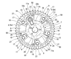
- FIG. 1 is an exploded perspective view showing a first embodiment of a valve timing control device according to the present invention. It is the schematic which shows the hydraulic circuit of the valve timing control apparatus of this embodiment. It is an operation explanatory view showing the state where valve timing by this embodiment was controlled to the retard side. It is effect
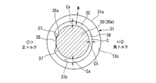
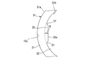
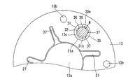
- action explanatory drawing which shows the state which controlled the valve timing by this embodiment to the advance side. It is an expanded sectional view showing the locked state by the lock mechanism provided for this embodiment. It is a front view which shows in a partial cross section the state where the lock pin was engaged in the lock hole provided in the rear plate provided for this embodiment. It is an enlarged view of the lock hole structure part and lock hole which are shown in FIG.
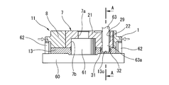
- FIG. 11 is a cross-sectional view taken along the line AA of FIG. 10, where A shows an initial step of the assembly procedure, B shows a next step of the assembly procedure, and C is a cross-sectional view of a main part showing a final step. It is a front view which shows 2nd Embodiment of this invention and shows the state by which the lock pin was engage
- First Embodiment 1 to 4 show a first embodiment in which a valve timing control device is provided on the intake valve side, and a sprocket 1 that is a drive rotor that is rotationally driven via a timing chain by a crankshaft outside the engine, A camshaft 2 provided so as to be relatively rotatable with respect to the sprocket 1 and a phase conversion mechanism 3 disposed between the sprocket 1 and the camshaft 2 to convert the relative rotation positions of the both 1 and 2. And a hydraulic circuit 4 for operating the phase conversion mechanism 3.
- the camshaft 2 is rotatably supported by a cylinder head (not shown) via a cam bearing, and a plurality of drive cams for opening the intake valve via a valve lifter are integrally provided at a predetermined position on the outer peripheral surface.
- a female screw hole 2b into which a cam bolt 6 described later is screwed is formed in the inner axial direction of the one end 2a.
- the phase conversion mechanism 3 is fixed in the axial direction by the cam bolt 6 to the housing 5 disposed on the one end 2a side of the camshaft 2 and the camshaft 2, and is freely rotatable in the housing 5.
- the accommodated vane member 7, five first to fourth shoes 8 formed on the inner peripheral surface of the housing 5, and five vanes 22 to 26 (to be described later) of the vane member 7, Are provided with five retard hydraulic chambers 9 and advanced hydraulic chambers 10, respectively.
- the housing 5 includes a substantially cylindrical (hollow) housing main body 11 having the sprocket 1 integrally provided on the outer peripheral surface, a front plate 12 that is a closing plate that closes the front and rear opening ends of the housing main body 11, and a rear plate.
- a front plate 12 and a rear plate 13 (sprocket 1) are integrally coupled to the housing main body 11 by means of five bolts 14 from the axial direction.
- the housing body 11 is integrally formed of a sintered metal material, and the five first to fifth shoes 8 are integrally protruded inward at substantially equal positions in the circumferential direction of the inner peripheral surface. .
- Each shoe 8 is formed in a substantially U-shaped trapezoidal shape when viewed from the side, and slides on the outer periphery of the rotor 21 of the vane member 7 in a seal groove formed along the axial direction at each tip portion.
- the substantially U-shaped seal members 16 that are in contact with each other are fitted and fixed.
- bolt insertion holes 17 through which the bolts 14 are inserted are formed through the outer peripheral side of each shoe 8 in the radial direction, that is, the inner axial direction on the base side that is a coupling portion with respect to the housing body 11.
- one first shoe 8a is one side in the circumferential direction of the base, that is, the right corner in FIG. 3, as shown in FIG. 1, FIG. 3, FIG.
- the built-up portion 18 is integrally formed.
- the built-up portion 18 has an inner peripheral surface 18a formed in a substantially arc shape, and is gently curved (arc-shaped) along the inner peripheral surface 11b of the housing body 11 from the rising portion of one side surface of the first shoe 8a. ).
- the strength of the base portion of the first shoe 8 a is higher than that of the other shoes 8.
- the front plate 12 is formed into a relatively thin disk shape by press molding, has a large-diameter hole 12a through which the cam bolt 6 is inserted, and is arranged at equidistant positions in the circumferential direction on the outer peripheral side. Are formed with five bolt insertion holes 12b through which the bolts 14 are inserted.
- the rear plate 13 is made of a ferrous metal and is relatively thick.
- a support hole 13a is inserted in the center of the cam shaft 2 so that the end portion 2a of the cam shaft 2 is rotatably supported.
- Female screw holes 13b into which the male screw portions at the tip portions of the bolts 14 are screwed are formed at equal circumferential positions on the side.
- five advance angle side oil holes 27 communicating with each advance angle hydraulic chamber 10 are formed in the radial direction of the hole edge side of the support hole 13a. .
- the vane member 7 is integrally formed of a metal material, and, as shown in FIGS. 2 and 3, one end portion of the camshaft 2 by the cam bolt 6 inserted from the axial direction into an insertion hole 7a formed through the center.
- the rotor 21 has a columnar fitting groove 7b in which one end 2a of the camshaft 2 is fitted and held at the center, and is fitted and fixed to the upper surface of the tip of each shoe 8.
- the seal member 16 is rotatably supported while sliding. Further, as shown in FIG. 3, the five retarded-side oil holes 28 communicating with the respective retarded hydraulic chambers 9 are formed penetratingly formed in the radial directions on both sides of each of the vanes 22 to 25, respectively. .
- each of the vanes 22 to 25 is disposed between the shoes 8 and has an inner periphery of the housing main body 11 in a seal groove formed in an axial direction on each tip surface.
- a U-shaped seal member 50 slidably contacting the surface 11b is fitted.
- each of the vanes 22 to 26 has a specific first vane 22 having a maximum width, and the other four vanes 23 to 26 are sufficiently smaller than the first vane 22 and substantially the same width. Is set.
- the first vane 22 When the vane member 7 rotates in the maximum counterclockwise direction shown in FIG. 3, the first vane 22 has one side abutting against the opposite side surface of the first shoe 8 a and is relative to the housing 5 on the maximum retardation side.
- the rotation position is restricted and the vane member 7 rotates in the maximum clockwise direction shown in FIG. 4, the protrusion 22b formed on the other side abuts against the opposite side surface of the second shoe 8b and reaches the maximum advance angle side.
- the relative rotational position is regulated.
- a lock mechanism for restricting free rotation of the vane member 7 is provided between the first vane 22 and the rear plate 13.
- the locking mechanism is slidably accommodated in a sliding hole 29 formed so as to penetrate the first vane 22 in the inner axial direction.
- a lock pin 30 that is movable forward and backward, an annular lock hole component 31 fixed to a holding hole 13c formed on the inner end surface of the rear plate 13 on the housing body 11, and the lock hole configuration
- a lock hole 32 formed inside the portion 31 and engaged with the tip 30a of the lock pin 30 to lock the vane member 7, and the tip 30a of the lock pin 30 according to the engine starting state 32, and an engagement / disengagement mechanism that releases or engages.
- the sliding hole 29 has an inner peripheral surface formed with a large and small step diameter, and has a small diameter hole on the front end side and a large diameter hole on the rear end side, and an annular shape between the small diameter hole and the large diameter hole. Step portion 29a is formed.
- the lock pin 30 has a front end portion 30a formed in a solid shape, and is entirely formed in a cylindrical shape except for a flange-shaped ring portion 30b formed on the outer periphery of the rear end. To the vicinity of the tip portion 30a in the inner axial direction. Further, the tip portion 30a is formed with a chamfered portion so that the tip edge can be smoothly inserted when the tip edge is inserted into the lock hole 32 of the lock hole constituting portion 31.
- a cylindrical pressure receiving chamber 33 is formed between the stepped portion 29 a of the sliding hole 29 and the annular portion 30 b of the lock pin 30.
- the holding hole 13c is configured to prevent the lock hole constituting portion 31 from being moved to a predetermined position in the circumferential direction of the rear plate 13, that is, when the vane member 7 is rotated to a relative rotation position on the most retarded angle side with respect to the housing 5.
- the tip portion 30 a of the lock pin 30 is formed at a position where the lock pin 30 is engaged with the lock hole 32.
- the lock hole constituting portion 31 is formed in an annular shape, and its width and thickness W are formed substantially uniformly as a whole, and the outer peripheral surface 31a is formed in the holding hole 13c. It is press-fitted and fixed to the peripheral surface. Further, the lock hole constituting portion 31 is integrally formed with a protruding portion 35 at a position on the left side of the inner peripheral surface 31b in FIGS. 6 and 7, that is, at a position on the retard side of the vane member 7. In addition, a portion of the inner peripheral surface 31b on the side opposite to the protruding portion 35 in the radial direction is formed in the arc portion 36.
- the protrusion 35 is configured such that the tip of the lock pin 30 is moved when the vane member 7 is rotated to the relative rotation position on the most retarded angle side with respect to the housing 5 in accordance with the formation position of the holding hole 13c.
- the outer peripheral surface 30a is provided at a position where the vane member 7 comes into contact with the rotation direction of the vane member 7, and the front end surface 35a facing the lock pin 30 is formed flat.
- the flat end surface 35 a is formed substantially perpendicular to the rotation direction of the vane member 7 of the lock hole 32.
- the vane member 7 is formed substantially parallel to a plane connecting the rotation axis center of the vane member 7 and the radial center of the lock hole 32.
- the tip surface 35a is formed along the tangential direction of the inner peripheral surface 31b of the lock hole constituting portion 31, and the surface area of the tip surface 35a is that the tip portion 30a of the lock pin 30 is within the lock hole 32 in FIG.
- the outer peripheral surface of the distal end portion 30a is always formed in such a size that it always contacts even when it is moved to the maximum in the vertical direction.
- the maximum protrusion amount H from the imaginary line formed by the radius of curvature of the inner peripheral surface 31b of the lock hole constituting portion 31 of the protrusion 35 is the tip of the lock pin 30 as shown in FIG.
- the amount of protrusion is set such that a clearance C of about 60 ⁇ m is formed between the outer peripheral surface and the outer peripheral surface.
- the clearance C may be set within a range of about 30 to 90 ⁇ m.
- the arc portion 36 is formed such that the arc length X is longer than the arc length of the right half of the outer peripheral surface of the lock pin tip 30a in the drawing, and the radius of curvature r is
- the radius of curvature r ′ of the lock hole constituting portion 31 is set to be smaller than the radius of curvature r ′ of the lock pin 30 and is substantially the same as or slightly larger than the radius of curvature of the tip portion 30 a of the lock pin 30. Therefore, the inner peripheral surface of the lock hole 32 is formed in an oval shape due to the presence of the arc portion 36.
- the protrusion 35 has a pair of concave portions 37, 37 formed on both sides in the circumferential direction, that is, on both sides in the circumferential direction of the inner peripheral surface 31 b of the lock hole constituting portion 31. ing.
- Each of the recesses 37 is formed in a gentle circular arc shape from the front end surface 35a of the protrusion 35 toward the inner peripheral surface 31b, and is coupled with each outer end edge smoothly connected to the inner peripheral surface 31b. Has been.
- the lock hole 32 is formed at a position biased toward the advance hydraulic chamber 10 side (the retard angle side of the vane member 7) in the circumferential direction. This formation position is the formation position of the holding hole 13c described above.
- the vane member 7 is set so that the tip 30a of the lock pin 30 is engaged with the housing 5 at the conversion angle position where the relative rotation angle is the most retarded angle side. Yes.
- a rectangular notch groove 7c is formed on the inner surface of the front plate 12 on the rear end side of the sliding hole 29, and this notch groove 7c is communicated with outside air so that it functions as an air vent hole.
- the good slidability of the lock pin 30 is always ensured within the rotation range of the vane member 7.
- the engagement / disengagement mechanism is elastically mounted between the rear end portion of the lock pin 30 and the inner end surface of the front plate 12, and a coil spring 34 that urges the lock pin 30 in the advance direction, and the lock hole 32 and the pressure receiving member.
- a release hydraulic circuit (not shown) that supplies hydraulic pressure into the chamber 33 to retract the lock pin 30 is configured. This release hydraulic circuit supplies the hydraulic pressure selectively supplied to each retarded hydraulic chamber 9 and each advanced hydraulic chamber 10 to the inside of the first vane 22 and to the interior of the first vane 22, as shown in FIGS.
- the pressure receiving chamber 33 and the lock hole 32 are supplied and discharged through oil holes 38 and 39 formed on the side surfaces.
- the hydraulic circuit 4 selectively supplies hydraulic oil to the oil chambers 9 and 10, or selectively discharges hydraulic oil in the oil chambers 9 and 10, as shown in FIG.
- the retard angle side passage 40 communicating with each of the retard angle side oil holes 28, the advance angle side passage 41 communicating with the advance angle side oil hole 27, and the electromagnetic switching valve 42 in each of the passages 40, 41.
- an oil pump 43 that selectively supplies hydraulic pressure via a drain passage 44 that selectively communicates with the passages 40 and 41 via an electromagnetic switching valve 42.
- Both the passages 40 and 41 communicate with the respective oil holes 27 and 28 through oil passage holes 40a and 41a and groove grooves 40b and 41b formed in the camshaft 2 along the radial direction and the axial direction. is doing.
- the electromagnetic switching valve 42 is a two-way valve, and selectively switches between the passages 40 and 41, the discharge passage 43a of the oil pump 43, and the drain passage 44 by an output signal from a controller (not shown). It has become.
- an internal computer inputs information signals from various sensors such as a crank angle sensor, an air flow meter, a water temperature sensor, and a throttle valve opening sensor (not shown) to detect the current engine operating state, A control current is output to the electromagnetic coil of the electromagnetic switching valve 42 in accordance with the engine operating state.
- a large-diameter cylindrical camshaft-equivalent jig 61 is fixed in advance to the bottom surface of a circular groove formed substantially at the center of the upper surface of the fixed base 60.
- the rear plate 13 in which the lock hole component 31 is press-fitted and fixed in the holding hole 13c in advance is positioned while being inserted into the camshaft equivalent jig 61 through the support hole 13a, and the upper surface of the fixed base 60 is positioned. Placed on. Thereafter, the housing body 11 in which the vane member 7 is previously incorporated is placed on the upper surface of the rear plate 13. At this time, the cam shaft equivalent jig 61 is fitted with the fitting groove 7b of the vane member 7 to perform positioning in the radial direction. At this time, appropriate alignment between the sliding hole 29 and the lock hole 32 of the vane member 7 is performed.
- the housing body 11 is fixed in a sandwiched state from the radially inner direction (arrow direction) by a plurality of fixing pins 62 protruding upward from the upper surface of the outer peripheral portion of the fixed base 60.
- the movement of the housing body 11 in the rotational direction is restricted, but the rear plate 13 and the vane member 7 can rotate and slide with respect to the housing body 11.
- the tip 63a of the cylindrical lock pin equivalent jig 63 is inserted into the lock hole 32 from above the sliding hole 29 of the vane member 7 and into the lock hole 32. Insert. As a result, the axial centers of the sliding hole 29 and the lock hole 32 are aligned.
- the lock pin equivalent jig 63 is used to rotate the vane member 7 and the rear plate 13 around the camshaft equivalent jig 61 in the arrow direction (retard direction) together. Let Then, the distal end portion 63 a of the lock pin equivalent jig 63 moves in the same direction in the lock hole 32, and the side surface of the distal end portion 61 a comes into contact with the distal end surface 35 a of the projection portion 35 of the lock hole constituting portion 31. Then, one side surface of the first vane 22 on the side of the notch 22a comes into contact with the opposite side surface of the first shoe 8a.
- the controller energizes the electromagnetic coil of the electromagnetic switching valve 42.
- the discharge passage 43a of the oil pump 43 and the advance side passage 41 are communicated, and at the same time, the retard side passage 40 and the drain passage 44 are communicated.
- the hydraulic oil discharged from the oil pump 43 flows into the advance hydraulic chamber 10 via the advance side passage 41, and the advance hydraulic chamber 10 becomes high pressure, while the retard hydraulic chamber 9
- the hydraulic fluid inside is discharged from the drain passage 44 into the oil pan 45 through the retard side passage 40, and the inside of the retard hydraulic chamber 9 becomes low pressure.
- the vane member 7 rotates clockwise as shown in FIG. 4 so that the protrusion 22b of the first vane 22 faces one side surface of the second shoe 8b. And further clockwise rotation is restricted. Thereby, the relative rotation angle of the vane member 7, that is, the camshaft 2, is converted to the most advanced angle side with respect to the sprocket 1 (housing main body 11).
- the vane member 7 rotates counterclockwise with respect to the housing 5 so that one side surface of the first vane 22 on the side of the notch 22a is pressed against the opposite side surface of the first shoe 8a.
- further counterclockwise rotation is restricted.
- the relative rotation phase of the camshaft 2 with respect to the sprocket 1 is converted to the most retarded angle side.
- the vane member 7 is rotated relative to the retard side by the alternating torque acting on the camshaft 2 to move forward at a predetermined rotational position, the lock pin 30 is advanced by the spring force of the coil spring 34, and the tip 30a is The vane member 7 is locked into the housing 5 by engaging with the lock hole 32.
- the vane member 7 and the lock hole component 31 are connected to the lock pin during the assembly, instead of assembling based on the positioning pin as in the prior art. Since the housing body 11 is rotated together to the retard angle side via the corresponding jig 63, the angle accuracy of each member such as the vane member 7 and the rear plate 13 can be excluded from the factors.
- the lock pin 30 can be smoothly engaged with and disengaged from the lock hole 32 also from this point. Generation of rattling between the lock pin 30 and the lock hole 32 (lock hole component 31) due to the alternating torque acting on the camshaft 2 can be suppressed.
- the circumferential clearance C1 can be reduced by providing the projection 35, and the tip end surface 35a of the projection is flattened in the rotational direction. Even if the vane member 7 is displaced in the radial direction and the place where the tip portion 30a of the lock pin 30 contacts on the flat tip surface 35a is shifted, the influence on the clearance C1 is suppressed.
- the vane member 7 and the lock hole constituting portion 31 are brought together with the housing main body 11 via the lock pin equivalent jig 63.
- the vane member 7 is locked at the most retarded position
- the first vane 22 is rotated to the retarded angle side so that one side surface of the first vane 22 on the side of the notch 22a contacts the opposite side surface of the first shoe 8a.
- the positioning accuracy in the rotational direction of the vane member 7 of the first vane 22, the first shoe 8 a, and the lock hole constituting portion 31 can be improved.
- the lock pin equivalent jig 63 causes one side surface of the first vane 22 on the cutout portion 22a side to abut on the opposite side surface of the first shoe 8a, and the tip portion 30a of the lock pin 30 is in contact with the tip surface 35a of the projection portion 35. Since it is assembled on the basis of the contact state, when the vane member 7 is locked at the most retarded position, it is between the one side surface of the first vane 22 on the notch 22a side and the opposite side surface of the first shoe 8a. The clearance can be reduced.
- the positional deviation when the camshaft 2 is fitted is suppressed. Accordingly, since the radial clearance C2 can be made relatively large, smooth engagement / disengagement of the lock pin 30 with respect to the lock hole 32 can be ensured, and the circumferential clearance C1 can be reduced by the protrusion 35. Therefore, the backlash between the distal end portion 30a of the lock pin 30 and the lock hole 32 due to the alternating torque of the camshaft 2 can be sufficiently suppressed.
- the distal end portion of the lock pin 30 is caused by the alternating torque of the camshaft 2 or the like. Even when a shearing force acts on 30a, the lock pin 30 does not come out of the lock hole 32 inadvertently, and a stable engagement state can be obtained.
- the arc-shaped concave portions 37 and 37 are formed on both sides of the projecting portion 35, the operation supplied to the retard hydraulic chamber 9 and the advanced hydraulic chamber 10 at the time of unlocking described above. Since oil is quickly supplied from the pressure receiving chamber 33 and the oil hole 39 through the recesses 37 into the lock hole 32 (holding hole 13c), the responsiveness of the lock pin 30 coming out from the lock hole 32 is good. become. Further, since the hydraulic oil remaining in the lock hole 32 at the time of locking can be quickly discharged to the pressure receiving chamber 33 and the oil hole 39 through the recesses 37, the lock responsiveness of the lock pin 30 is improved.
- the lock pin 30 is engaged with the lock hole 32 in the locked state. 7, the negative alternating torque in the direction of the white arrow in FIG. The pressure is reduced. Therefore, it is possible to suppress the occurrence of collision hitting sound and to suppress the occurrence of wear between the arc portion 36 and the lock pin tip portion 30a.
- the lock pin 30 engages with the lock hole 32 at the most retarded angle.
- one side surface of the first vane 22 on the side of the notch 22a is the opposite side surface of the first shoe 8a.
- the distal end portion 30a of the lock pin 30 is in contact with the distal end surface 35a of the projection portion 35.
- this surface pressure is applied to one side surface of the first vane 22 on the notch portion 22a side and the opposite side surface of the first shoe 8a.
- the surface pressure is also reduced by being dispersed at the contact points. Therefore, the tip surface 35a of the projection 35 is formed in a flat shape, and the contact area with the arc pin 36 with the lock pin tip 30a is small, but the surface pressure is dispersed and becomes small.
- FIG. 12 shows the second embodiment, the basic structure is the same as the first embodiment, except that the arc portion 36 provided on the inner peripheral surface 31b of the lock hole constituting portion 31 is abolished, A second protrusion 46 is formed at a position facing the protrusion 35 from the radial direction.
- the second protrusion 46 has substantially the same configuration as the first protrusion 35 in width, height, and the like, and the tip surface 46a is also formed in a flat shape. A width across flats is formed together with the front end surface 35a of the first protrusion 35 parallel to 46a. Further, two arc-shaped second recesses 47, 47 are formed on both sides of the second protrusion 46, and each recess 47 has the same configuration as the first recesses 37, 37 of the first embodiment. It is.
- the lock pin equivalent treatment can be performed at the time of the assembly described in FIGS. 10 and 11.
- the clearance width between the outer peripheral surface of the lock pin equivalent jig 63 and the tip end surfaces 35a, 46a of the two projections 35, 46 is restricted. Even if the radial clearance C2 between the lock hole 32 and the lock pin 30 varies, the circumferential clearance C1 can be set to a desired size, for example, sufficiently small.
- second recesses 47 and 47 are formed on both sides of the second protrusion 46, in combination with the presence of the first recesses 37 and 37, lock holes are formed from the hydraulic chambers 9 and 10, respectively.
- the supply efficiency of the hydraulic oil to 32 and the discharge efficiency of the hydraulic oil from each lock hole 32 can be further increased.
- FIG. 14 shows a third embodiment in which the valve timing control device of the present invention is applied to the exhaust valve side. Since the basic structure is the same as that of the first embodiment, the same members are denoted by the same reference numerals. Is omitted. The difference from the first embodiment is that a torsion spring 70 for urging the vane member 7 in the most advanced angle direction is disposed in a cylindrical portion 12c formed integrally with the inner peripheral portion of the front plate 12, and the rear The formation position of the holding hole 13 c of the plate 13 is formed at a position where the vane member 7 is relatively rotated to the most advanced angle side through the spring force of the torsion spring 70.
- the lock hole constituting portion 31 press-fitted and fixed to the holding hole 13c has a projection 35 having an inner peripheral surface opposite to the structure of the lock hole constituting portion 31 of the first embodiment. It is provided at a position on the advance side of 31b.
- the other configuration is the same as that of the first embodiment, and the front end surface 35a of the projection 35 is formed in a flat shape, and recesses 37, 37 are formed on both sides of the projection 35.
- an arc portion 36 is formed at a position opposite to the projection 35 in the radial direction (position on the retarded angle side), and the inner peripheral surface 31b of the lock hole constituting portion 31 and the outer periphery of the distal end portion 30a of the lock pin 30
- the clearance C1 in the circumferential direction between the surfaces is smaller than the clearance C2 in the radial direction.
- each of the constituent members is also assembled in the steps shown in FIGS. 11A to 11C as in the first embodiment.
- the vane member 7 is applied by the spring force of the torsion spring 70 when the engine is stopped.
- the lock pin 30 rotates relative to the housing 5 to the most advanced position, the lock pin 30 can smoothly engage with the lock hole 32.
- the lock pin 30 can be smoothly engaged with and disengaged from the lock hole 32 also from this point, Occurrence of rattling between the lock pin 30 and the lock hole 32 (lock hole constituent portion 31) due to the alternating torque that acts can be suppressed, and generation of hitting sound can be sufficiently suppressed.
- FIG. 16 shows the fourth embodiment, and the basic structure is the same as that of the first embodiment, except that the front end surface 35a of the protrusion 35 provided on the inner peripheral surface 31b of the lock hole constituting portion 31 is locked. It is formed in an arc shape along the outer peripheral surface of the pin 30.
- the circumferential clearance C1 can be set to a desired size, for example, sufficiently small. Since the tip end surface 35a of the projection 35 is formed in an arc shape, the surface pressure when the tip end 30a of the lock pin 30 contacts the tip end surface 35a of the projection 35 can be reduced. Can be reduced. Therefore, it is possible to suppress the occurrence of impact sound and to suppress the occurrence of wear between the tip surface 35a of the protrusion 35 and the lock pin tip 30a.
- the radius of curvature of the arcuate tip surface 35a of this embodiment is formed larger than the radius of curvature of the outer periphery of the tip portion 30a of the lock pin 30. Therefore, the influence on the clearance C1 by the position shift in the radial direction of the vane member 7 and the rear plate 13 can be suppressed during assembly.
- the present invention is not limited to the configuration of each of the embodiments described above.
- the lock hole component 31 is not circular but is formed in an elliptical shape that is long in the radial direction, and between the lock pin 30 and the lock pin 30. It is also possible to make the circumferential clearance C1 smaller than the radial clearance C2.
- the sprocket 1 integrally formed on the outer periphery of the housing body 11 can be replaced with a pulley, and the sprocket 1 and the pulley can be formed on the outer periphery of the rear plate 13.
- the lock hole 32 is not necessarily formed by the lock hole constituting portion 31, and may be directly formed in the holding hole 13c, for example, in this case, in this case, the protrusion 35 or the arc portion 36 and the like are directly formed on the inner peripheral surface of the holding hole 13c.
Landscapes
- Engineering & Computer Science (AREA)
- Mechanical Engineering (AREA)
- General Engineering & Computer Science (AREA)
- Valve Device For Special Equipments (AREA)
Abstract
Description
〔第1実施形態〕
図1~図4はバルブタイミング制御装置を吸気弁側に設けた第1実施形態を示し、機関の図外のクランクシャフトによってタイミングチェーンを介して回転駆動される駆動回転体であるスプロケット1と、該スプロケット1に対して相対回動可能に設けられたカムシャフト2と、スプロケット1とカムシャフト2との間に配置されて、該両者1,2の相対回動位置を変換する位相変換機構3と、該位相変換機構3を作動させる油圧回路4と、を備えている。
〔バルブタイミング制御装置の組立方法〕
次に、前記ハウジング本体11に対する前記ベーン部材7やロック機構、フロントプレート12,リアプレート13などのバルブタイミング制御装置の組立方法について説明する。
〔本実施形態の作用〕
以下、本実施形態の作用を説明すれば、まず、機関始動時は、図3、図5に示すように、予めロックピン30の先端部30aがロック穴32内に係入して、ベーン部材7を始動に最適な最遅角側の位置に拘束している。このため、イグニッションスイッチをオン操作して始動が開始されると、スムーズなクランキングによって良好な始動性が得られる。
〔第2実施形態〕
図12は第2実施形態を示し、基本構造は第1実施形態と同じであるが、異なる点は前記ロック穴構成部31の内周面31bに設けられた前記円弧部36を廃止して、前記突起部35と径方向から対向する位置に、第2突起部46を形成したものである。
〔第3実施形態〕
図14は本発明のバルブタイミング制御装置を排気弁側に適用した第3実施形態を示し、基本構造は第1実施形態と同様であるから、同一部材には同一に符番を付して説明を省略する。第1実施形態と異なるところは、フロントプレート12の内周部に一体に形成された円筒部12cに、前記ベーン部材7を最進角方向へ付勢するトーションスプリング70を配置すると共に、前記リアプレート13の保持穴13cの形成位置を、前記ベーン部材7がトーションスプリング70のばね力を介して最進角側に相対回転した位置に形成したものである。
〔第4実施形態〕
図16は第4実施形態を示し、基本構造は第1実施形態と同じであるが、異なる点は前記ロック穴構成部31の内周面31bに設けられた突起部35の先端面35aをロックピン30の外周面に沿って円弧状に形成したものである。
Claims (14)
- クランクシャフトから回転力が伝達され、内部に複数の作動室を有するハウジング本体と、
カムシャフトに固定されると共に、前記複数の作動室を進角作動室と遅角作動室に隔成する複数のベーンを有し、前記進角作動室と遅角作動室へ油圧を給排することによって前記ハウジング本体に対して進角側あるいは遅角側に回動するベーン部材と、
前記ハウジング本体の軸方向両端開口をそれぞれ閉塞する閉塞プレートと、
前記ベーンの内部に前記カムシャフトの軸方向に沿って形成された摺動用孔と、
該摺動用孔に進退自在に設けられたロック部材と、
前記閉塞プレートの前記作動室側に設けられ、前記ロック部材の先端部が係入するロック穴と、
を備え、
前記ロック穴は、内周面のうち、前記ベーン部材の周方向の一端側または他端側の少なくとも一方に先端面が平坦状の突起部が形成されていることを特徴とする内燃機関のバルブタイミング制御装置。 - 請求項1に記載の内燃機関のバルブタイミング制御装置において、
前記ロック穴は、前記突起部の前記ロック穴の円周方向の両側部に、前記ロック穴の内周面と連続する凹部が形成されていることを特徴とする内燃機関のバルブタイミング制御装置。 - 請求項2に記載の内燃機関のバルブタイミング制御装置において、
前記ロック部材は、前記ロック穴に係入する先端部が円柱状に形成されていることを特徴とする内燃機関のバルブタイミング制御装置。 - 請求項3に記載の内燃機関のバルブタイミング制御装置において、
前記ロック穴は、前記突起部の先端面と該先端面に径方向から対向する内面との間の巾長さが、前記突起部と軸直角方向位置する対向内面との間の巾長さよりも小さいことを特徴とする内燃機関のバルブタイミング制御装置。 - 請求項3に記載の内燃機関のバルブタイミング制御装置において、
前記ロック穴は、前記突起部の先端面と前記ロック穴の径方向から対向する内面が円弧状に形成されていることを特徴とする内燃機関のバルブタイミング制御装置。 - 請求項3に記載の内燃機関のバルブタイミング制御装置において、
前記ロック穴は、前記突起部の先端面と、該先端面に前記ロック穴の径方向から対向する内面が平坦状に形成されていることを特徴とする内燃機関のバルブタイミング制御装置。 - 請求項3に記載の内燃機関のバルブタイミング制御装置において、
前記ロック部材が前記ロック穴に係入している状態で、前記ロック部材の外周面が前記突起部の先端面が接触可能に設けられていることを特徴とする内燃機関のバルブタイミング制御装置。 - 請求項3に記載の内燃機関のバルブタイミング制御装置において、
前記ロック部材は、前記先端部の先端縁に面取り部が形成されていることを特徴とする内燃機関のバルブタイミング制御装置。 - クランクシャフトから回転力が伝達すると共に、径方向内側に向かって突出する複数のシューが設けられた中空状のハウジング本体と、
カムシャフトに固定されると共に、前記各シューの間に形成される複数の作動室を進角作動室と遅角作動室に隔成する複数のベーンを有し、前記進角作動室と遅角作動室へ油圧を給排することによって前記ハウジング本体に対して進角側あるいは遅角側に回動するベーン部材と、
前記ハウジング本体の軸方向両端開口をそれぞれ閉塞する閉塞プレートと、
前記ベーンの内部に前記カムシャフトの軸方向に沿って形成された摺動用孔と、
該摺動用孔に進退自在に設けられたロック部材と、
前記閉塞プレートの前記作動室側に設けられ、前記ロック部材の先端部が係入するロック穴と、
を備え、
前記ロック穴は、内周のうち、前記ベーン部材の周方向の一端側または他端側の少なくとも一方に突起部が設けられている共に、該突起部の先端面が前記ロック穴の円周方向に沿った円弧状に形成されていることを特徴とする内燃機関のバルブタイミング制御装置。 - 請求項9に記載の内燃機関のバルブタイミング制御装置において、
前記ロック穴は、前記突起部の前記ロック穴の円周方向の両側部に、前記ロック穴の内周面と連続する凹部が形成されていることを特徴とする内燃機関のバルブタイミング制御装置。 - 請求項10に記載の内燃機関のバルブタイミング制御装置において、
前記ロック部材は、前記ロック穴に係入する先端部が円柱状に形成されていることを特徴とする内燃機関のバルブタイミング制御装置。 - 請求項11に記載の内燃機関のバルブタイミング制御装置において、
前記ロック穴は、前記突起部の円弧状の先端面と該先端面に径方向から対向する内面との間の巾長さが、前記突起部と軸直角方向位置する対向内面との間の巾長さよりも小さいことを特徴とする内燃機関のバルブタイミング制御装置。 - 請求項12に記載の内燃機関のバルブタイミング制御装置において、
前記ロック穴は、前記突起部の先端面と径方向から対向する内面の曲率半径が前記ロック部材の先端部外周面の曲率半径よりも大きく形成されていることを特徴とする内燃機関のバルブタイミング制御装置。 - クランクシャフトから回転力が伝達され、内周面に径方向内側に向かって突設された複数のシューを有する中空状のハウジング本体と、
該ハウジング本体の軸方向両端開口を閉塞する閉塞プレートと、
カムシャフトに固定され、前記複数のシューの間に形成された作動室を進角作動室と遅角作動室に隔成する複数のベーンを有すると共に、前記進角作動室と遅角作動室へ油圧を給排することによって前記ハウジング本体に対して進角側あるいは遅角側に回動するベーンロータと、
前記ベーンロータの内部に、前記カムシャフトの軸方向に沿って形成された摺動用孔と、
該摺動用孔内に進退自在に設けられた横断面ほぼ円形状のロック部材と、
前記閉塞プレートの前記作動室側に設けられ、前記ベーンロータが最進角位置または最遅角位置あるいは該最進角と最遅角の間の中間位置において前記ロック部材の先端部が係入するロック穴と、
を備え、
前記前記ロック穴は、内周面のうち、前記ベーンロータの周方向の一端側または他端側に先端面が平坦状の突起部が形成されている内燃機関のバルブタイミング制御装置の組立方法であって、
前記ハウジング本体または前記閉塞プレートのうち、一方を固定して、他方と前記ベーンロータを一緒に軸回りに回転可能に保持する第1工程と、
前記ベーンロータの摺動用孔内に前記ロック部材相当の治具ピンを挿入する第2工程と、
前記固定されていない前記ハウジング本体または閉塞プレートの他方を前記ベーンロータに対して回転させて、前記治具ピンの先端部を前記ロック穴に挿入する第3工程と、
前記治具ピンの外周面を、前記摺動用孔の内周面に当接させて前記ベーンロータを一方向へ回転させることにより前記突起部の先端面に当接させる第4工程と、
前記治具ピンを前記ロック穴と摺動用孔から抜き取った後に、前記ロック部材を前記摺動用孔とロック穴に挿入する第5工程と、
を備えたことを特徴とする内燃機関のバルブタイミング制御装置の組立方法。
Priority Applications (3)
| Application Number | Priority Date | Filing Date | Title |
|---|---|---|---|
| US15/543,871 US10371019B2 (en) | 2015-01-16 | 2015-11-27 | Valve timing control device for internal combustion engine |
| JP2016569248A JP6259130B2 (ja) | 2015-01-16 | 2015-11-27 | 内燃機関のバルブタイミング制御装置 |
| CN201580073468.6A CN107208506B (zh) | 2015-01-16 | 2015-11-27 | 内燃机的气门正时控制装置 |
Applications Claiming Priority (2)
| Application Number | Priority Date | Filing Date | Title |
|---|---|---|---|
| JP2015-006379 | 2015-01-16 | ||
| JP2015006379 | 2015-01-16 |
Publications (1)
| Publication Number | Publication Date |
|---|---|
| WO2016114019A1 true WO2016114019A1 (ja) | 2016-07-21 |
Family
ID=56405576
Family Applications (1)
| Application Number | Title | Priority Date | Filing Date |
|---|---|---|---|
| PCT/JP2015/083383 Ceased WO2016114019A1 (ja) | 2015-01-16 | 2015-11-27 | 内燃機関のバルブタイミング制御装置 |
Country Status (4)
| Country | Link |
|---|---|
| US (1) | US10371019B2 (ja) |
| JP (1) | JP6259130B2 (ja) |
| CN (1) | CN107208506B (ja) |
| WO (1) | WO2016114019A1 (ja) |
Cited By (3)
| Publication number | Priority date | Publication date | Assignee | Title |
|---|---|---|---|---|
| CN109312641A (zh) * | 2016-08-10 | 2019-02-05 | 日立汽车系统株式会社 | 内燃机的气门正时控制装置以及该气门正时控制装置的组装方法 |
| WO2021253387A1 (zh) * | 2020-06-19 | 2021-12-23 | 舍弗勒技术股份两合公司 | 凸轮轴相位器及其工作方法 |
| US11994043B2 (en) * | 2022-03-03 | 2024-05-28 | Schaeffler Technologies AG & Co. KG | Contaminant pathway for camshaft phaser |
Families Citing this family (2)
| Publication number | Priority date | Publication date | Assignee | Title |
|---|---|---|---|---|
| US10167747B2 (en) * | 2016-10-28 | 2019-01-01 | Schaeffler Technologies AG & Co. KG | Sheet metal locking cover for a cam phaser |
| US12098663B2 (en) * | 2022-03-02 | 2024-09-24 | Borgwarner Inc. | Hydraulic VCT end plate seal |
Citations (4)
| Publication number | Priority date | Publication date | Assignee | Title |
|---|---|---|---|---|
| JP2010001770A (ja) * | 2008-06-19 | 2010-01-07 | Hitachi Automotive Systems Ltd | 内燃機関のバルブタイミング制御装置 |
| JP2010019146A (ja) * | 2008-07-09 | 2010-01-28 | Aisin Seiki Co Ltd | 弁開閉時期制御装置 |
| JP2010242532A (ja) * | 2009-04-01 | 2010-10-28 | Toyota Motor Corp | 内燃機関の可変動弁装置 |
| JP2015059518A (ja) * | 2013-09-19 | 2015-03-30 | 日立オートモティブシステムズ株式会社 | 内燃機関の可変動弁装置 |
Family Cites Families (8)
| Publication number | Priority date | Publication date | Assignee | Title |
|---|---|---|---|---|
| US6817095B2 (en) * | 2002-06-11 | 2004-11-16 | Delphi Technologies, Inc. | Method for assembling a vane-type cam phaser |
| EP2123866B1 (en) | 2008-05-20 | 2013-01-30 | Aisin Seiki Kabushiki Kaisha | Valve timing control device |
| US8056519B2 (en) * | 2008-08-11 | 2011-11-15 | Delphi Technologies, Inc. | Camshaft phaser intermediate locking pin and seat |
| JP2011064105A (ja) * | 2009-09-16 | 2011-03-31 | Hitachi Automotive Systems Ltd | 内燃機関のバルブタイミング制御装置 |
| JP2012237196A (ja) | 2011-05-10 | 2012-12-06 | Hitachi Automotive Systems Ltd | 内燃機関のバルブタイミング制御装置 |
| US8544434B2 (en) * | 2011-11-23 | 2013-10-01 | Toyota Motor Engineering & Manufacturing North America, Inc. | Lock pin for variable valve timing mechanism |
| JP5835261B2 (ja) * | 2013-03-29 | 2015-12-24 | 株式会社デンソー | バルブタイミング調整装置の製造装置及び製造方法 |
| DE102013223301A1 (de) * | 2013-11-15 | 2015-05-21 | Schaeffler Technologies AG & Co. KG | Nockenwellenverstelleinrichtung |
-
2015
- 2015-11-27 JP JP2016569248A patent/JP6259130B2/ja not_active Expired - Fee Related
- 2015-11-27 US US15/543,871 patent/US10371019B2/en active Active
- 2015-11-27 CN CN201580073468.6A patent/CN107208506B/zh not_active Expired - Fee Related
- 2015-11-27 WO PCT/JP2015/083383 patent/WO2016114019A1/ja not_active Ceased
Patent Citations (4)
| Publication number | Priority date | Publication date | Assignee | Title |
|---|---|---|---|---|
| JP2010001770A (ja) * | 2008-06-19 | 2010-01-07 | Hitachi Automotive Systems Ltd | 内燃機関のバルブタイミング制御装置 |
| JP2010019146A (ja) * | 2008-07-09 | 2010-01-28 | Aisin Seiki Co Ltd | 弁開閉時期制御装置 |
| JP2010242532A (ja) * | 2009-04-01 | 2010-10-28 | Toyota Motor Corp | 内燃機関の可変動弁装置 |
| JP2015059518A (ja) * | 2013-09-19 | 2015-03-30 | 日立オートモティブシステムズ株式会社 | 内燃機関の可変動弁装置 |
Cited By (5)
| Publication number | Priority date | Publication date | Assignee | Title |
|---|---|---|---|---|
| CN109312641A (zh) * | 2016-08-10 | 2019-02-05 | 日立汽车系统株式会社 | 内燃机的气门正时控制装置以及该气门正时控制装置的组装方法 |
| US10808581B2 (en) | 2016-08-10 | 2020-10-20 | Hitachi Automotive Systems, Ltd. | Valve timing control device for internal combustion engine and method for assembling valve timing control device |
| CN109312641B (zh) * | 2016-08-10 | 2021-02-09 | 日立汽车系统株式会社 | 内燃机的气门正时控制装置以及该气门正时控制装置的组装方法 |
| WO2021253387A1 (zh) * | 2020-06-19 | 2021-12-23 | 舍弗勒技术股份两合公司 | 凸轮轴相位器及其工作方法 |
| US11994043B2 (en) * | 2022-03-03 | 2024-05-28 | Schaeffler Technologies AG & Co. KG | Contaminant pathway for camshaft phaser |
Also Published As
| Publication number | Publication date |
|---|---|
| JPWO2016114019A1 (ja) | 2017-08-17 |
| CN107208506B (zh) | 2019-06-21 |
| CN107208506A (zh) | 2017-09-26 |
| US10371019B2 (en) | 2019-08-06 |
| JP6259130B2 (ja) | 2018-01-10 |
| US20170370253A1 (en) | 2017-12-28 |
Similar Documents
| Publication | Publication Date | Title |
|---|---|---|
| JP4016020B2 (ja) | 内燃機関のバルブタイミング制御装置 | |
| JP6259130B2 (ja) | 内燃機関のバルブタイミング制御装置 | |
| US8011337B2 (en) | Valve timing adjusting apparatus | |
| JP2012237196A (ja) | 内燃機関のバルブタイミング制御装置 | |
| US20080022952A1 (en) | Valve timing control apparatus and its assembling method | |
| JP6109949B2 (ja) | 内燃機関のバルブタイミング制御装置 | |
| WO2015087649A1 (ja) | 内燃機関のバルブタイミング制御装置 | |
| JP2008240735A (ja) | 内燃機関のバルブタイミング制御装置 | |
| JP4126325B2 (ja) | 内燃機関のバルブタイミング制御装置用ハウジング | |
| JP5198395B2 (ja) | 内燃機関のバルブタイミング制御装置 | |
| JP5859751B2 (ja) | 内燃機関のバルブタイミング制御装置及びこの装置の製造方法 | |
| JP4304219B2 (ja) | 内燃機関のバルブタイミング制御装置及びその組立方法 | |
| JP2017031908A (ja) | 内燃機関のバルブタイミング制御装置 | |
| JP6312568B2 (ja) | 内燃機関のバルブタイミング制御装置 | |
| JP6567677B2 (ja) | 内燃機関のバルブタイミング制御装置 | |
| JP4083788B2 (ja) | 内燃機関のバルブタイミング制御装置用ハウジング | |
| JP6533322B2 (ja) | 内燃機関のバルブタイミング制御装置 | |
| JPWO2017104246A1 (ja) | 内燃機関のバルブタイミング制御装置 | |
| JP4000137B2 (ja) | 内燃機関のバルブタイミング制御装置 | |
| US20200049033A1 (en) | Valve timing control device for internal combustion engine | |
| CN109312641B (zh) | 内燃机的气门正时控制装置以及该气门正时控制装置的组装方法 | |
| WO2018168302A1 (ja) | 内燃機関の可変動弁装置 | |
| JP2008196495A (ja) | 内燃機関のバルブタイミング制御装置 | |
| JP2019052569A (ja) | 内燃機関の可変動弁装置及び可変動弁装置の組立方法 |
Legal Events
| Date | Code | Title | Description |
|---|---|---|---|
| 121 | Ep: the epo has been informed by wipo that ep was designated in this application |
Ref document number: 15877971 Country of ref document: EP Kind code of ref document: A1 |
|
| ENP | Entry into the national phase |
Ref document number: 2016569248 Country of ref document: JP Kind code of ref document: A |
|
| WWE | Wipo information: entry into national phase |
Ref document number: 15543871 Country of ref document: US |
|
| NENP | Non-entry into the national phase |
Ref country code: DE |
|
| 122 | Ep: pct application non-entry in european phase |
Ref document number: 15877971 Country of ref document: EP Kind code of ref document: A1 |