WO2016111008A1 - Ledランプ駆動装置 - Google Patents
Ledランプ駆動装置 Download PDFInfo
- Publication number
- WO2016111008A1 WO2016111008A1 PCT/JP2015/050518 JP2015050518W WO2016111008A1 WO 2016111008 A1 WO2016111008 A1 WO 2016111008A1 JP 2015050518 W JP2015050518 W JP 2015050518W WO 2016111008 A1 WO2016111008 A1 WO 2016111008A1
- Authority
- WO
- WIPO (PCT)
- Prior art keywords
- led lamp
- output voltage
- constant current
- state
- unit
- Prior art date
- Legal status (The legal status is an assumption and is not a legal conclusion. Google has not performed a legal analysis and makes no representation as to the accuracy of the status listed.)
- Ceased
Links
Images




Classifications
-
- H—ELECTRICITY
- H05—ELECTRIC TECHNIQUES NOT OTHERWISE PROVIDED FOR
- H05B—ELECTRIC HEATING; ELECTRIC LIGHT SOURCES NOT OTHERWISE PROVIDED FOR; CIRCUIT ARRANGEMENTS FOR ELECTRIC LIGHT SOURCES, IN GENERAL
- H05B47/00—Circuit arrangements for operating light sources in general, i.e. where the type of light source is not relevant
- H05B47/10—Controlling the light source
Definitions
- This invention relates to the LED lamp drive device which can switch the LED lamp to light.
- a vehicular lighting device including a plurality of LED lamps and an LED lamp driving device is known (for example, see Patent Document 1).
- the LED lamp driving device has a constant current power supply unit that outputs a constant current IOUT, and supplies the constant current IOUT to at least one of the plurality of LED lamps according to the control of the user. Thereby, the LED lamp to light can be switched.
- a vehicle lighting device is used as, for example, a headlight capable of switching between a high beam and a low beam.
- an object of the present invention is to provide an LED lamp driving device that can appropriately cope with abnormality of the LED lamp.
- An LED lamp driving device for driving an LED lamp unit including a first LED lamp and a second LED lamp connected in series, A constant current power supply unit having a current output terminal for outputting a constant current; A switching unit that supplies the constant current to at least one of the first LED lamp and the second LED lamp; A voltage detector for detecting an output voltage of the current output terminal; A control unit that controls the switching unit to switch the supply destination of the constant current when the output voltage is out of a predetermined output voltage range; It is characterized by that.
- the minimum value of the output voltage range is lower than the forward voltage of the first LED lamp and lower than the forward voltage of the second LED lamp,
- the maximum value of the output voltage range may be higher than the sum of the forward voltage of the first LED lamp and the forward voltage of the second LED lamp.
- the second LED lamp has an anode side terminal connected to a cathode side terminal of the first LED lamp, a cathode side terminal grounded,
- the switching unit includes a first state in which the constant current is supplied to the anode side terminal of the first LED lamp, a second state in which the constant current is supplied to the anode side terminal of the second LED lamp, and the first LED lamp Switching between a third state in which the constant current is supplied to the anode side terminal and the cathode side terminal of the first LED lamp is grounded;
- the control unit switches to the first state, the second state, or the third state according to an operation by a user, and when the output voltage is out of the output voltage range, Instead, the switching unit may be controlled to switch the supply destination of the constant current.
- the switching unit is A first switching element connected between the current output terminal and the anode side terminal of the first LED lamp; A second switching element connected between the current output terminal and a cathode side terminal of the first LED lamp; A third switching element connected between the cathode side terminal of the first LED lamp and the ground, In the first state, the first switching element is conductive, the second switching element and the third switching element are not conductive, In the second state, the second switching element is conductive, the first switching element and the third switching element are not conductive, In the third state, the first switching element and the third switching element are conducted, and the second switching element is not conducted.
- the control unit switches to the second state or the third state when the output voltage is out of the output voltage range in the first state, and the output voltage is out of the output voltage range in the second state.
- the switching unit may be controlled to switch to the third state when the output voltage is out of the range, and to switch to the second state when the output voltage is out of the output voltage range in the third state.
- the control unit is configured to output the output voltage in the second state when the output voltage is out of the output voltage range, and then in the third state, the output voltage is out of the output voltage range, or in the third state.
- the constant current power supply unit may stop the output of the constant current.
- An indicator driving unit for driving the indicator may cause the indicator driving unit to drive the indicator when the output voltage is out of the output voltage range.
- the LED lamp unit further includes a third LED lamp connected in series with the first LED lamp and the second LED lamp,
- the switching unit supplies the constant current to at least one of the first LED lamp, the second LED lamp, and the third LED lamp,
- the controller repeatedly supplies the constant current to the first LED lamp, the second LED lamp, and the third LED lamp one by one in order, and when the output voltage is out of the output voltage range,
- the switching unit may be controlled so that the constant current is intermittently supplied to two of the lamp, the second LED lamp, and the third LED lamp.
- An LED lamp driving device for driving an LED lamp unit including a first LED lamp and a second LED lamp, A first constant current power supply unit having a first current output terminal for outputting a first constant current; A second constant current power supply unit having a second current output terminal for outputting a second constant current; A switching unit for switching whether to supply the first constant current to the first LED lamp, and for switching whether to supply the second constant current to the second LED lamp; A voltage detector for detecting a first output voltage of the first current output terminal and a second output voltage of the second current output terminal; When the first output voltage is out of a predetermined first output voltage range, the second constant current is supplied to the second LED lamp, and the second output voltage is out of the predetermined second output voltage range.
- a control unit that controls the switching unit so as to supply the first constant current to the first LED lamp when disconnected. It is characterized by that.
- the minimum value of the first output voltage range is lower than the forward voltage of the first LED lamp,
- the maximum value of the first output voltage range is higher than the forward voltage of the first LED lamp,
- the minimum value of the second output voltage range is lower than the forward voltage of the second LED lamp,
- the maximum value of the second output voltage range may be higher than the forward voltage of the second LED lamp.
- the switching unit is A first state in which the first constant current is supplied to the anode side terminal of the first LED lamp and the second constant current is supplied to the anode side terminal of the second LED lamp; A second state in which the first constant current is not supplied to the anode side terminal of the first LED lamp and the second constant current is supplied to the anode side terminal of the second LED lamp; Switching between a third state in which the first constant current is supplied to the anode side terminal of the first LED lamp and the second constant current is not supplied to the anode side terminal of the second LED lamp;
- the control unit switches between the first state, the second state, and the third state according to an operation by a user, and when the first output voltage is out of the first output voltage range, the user
- the switching unit is switched so as to switch to the third state regardless of the operation by the user when the second output voltage is out of the second output voltage range without being operated by the user. You may control.
- the control unit may be configured such that when the first output voltage is out of the first output voltage range and then the second output voltage is out of the second output voltage range, or the second output voltage is the second output voltage.
- the first constant current and the second constant current power supply are connected to the first constant current power source and the second constant current power source. The constant current output may be stopped.
- An indicator driving unit for driving the indicator The controller drives the indicator to the indicator driving unit when the first output voltage is out of the first output voltage range or when the second output voltage is out of the second output voltage range. You may let them.
- a third constant current power supply unit having a third current output terminal for outputting a third constant current
- the LED lamp unit further includes a third LED lamp,
- the switching unit switches whether to supply the third constant current to the third LED lamp,
- the voltage detector detects a third output voltage of the third current output terminal;
- the controller repeatedly supplies the first, second, or third constant current to the first, second, and third LED lamps one by one in order, and the first output voltage is within the first output voltage range.
- the second and third constant currents are intermittently supplied to the second and third LED lamps.
- the first and second LED lamps are supplied with the first and third constant currents.
- the switching unit may be controlled so that the second constant current is intermittently supplied.
- the constant current supply destination when the output voltage is out of the output voltage range, the constant current supply destination is switched. Thereby, when a disconnection or a short circuit occurs in the LED lamp being turned on and the output voltage is out of the output voltage range, it is determined that there is an abnormality, and the other LED lamps can be turned on. Therefore, it is possible to appropriately cope with the abnormality of the LED lamp.
- FIG. 1 is a block diagram showing a schematic configuration of a vehicle lighting device 100 according to the first embodiment.
- the vehicle lighting device 100 includes an LED lamp unit 10, an indicator 20, a battery B, an ignition switch SW1, a high beam switch SWH, a low beam switch SWL, an LED lamp driving device 30, Is provided.
- the LED lamp unit 10 functions as a vehicle headlight and includes a first LED lamp 11 and a second LED lamp 12 connected in series.
- Each of the first LED lamp 11 and the second LED lamp 12 may include a plurality of LED elements connected in series or one LED element.
- the first LED lamp 11 is for a high beam
- the second LED lamp 12 is for a low beam.
- the anode side terminal 12a is connected to the cathode side terminal 11c of the first LED lamp 11, and the cathode side terminal 12c is grounded.
- the LED lamp unit 10 may include three or more LED lamps connected in series.
- the indicator 20 is provided at a position where the user (driver) of the vehicle can easily see and informs the user of an abnormality by lighting.
- the indicator 20 includes, for example, an LED element.
- the ignition switch SW1 switches whether to supply the electric power of the battery B to the LED lamp driving device 30 according to the operation of the user.
- the high beam switch SWH has one end grounded and the other end connected to the LED lamp driving device 30, and switches whether or not the first LED lamp 11 is lit according to the user's operation.
- the low beam switch SWL has one end grounded and the other end connected to the LED lamp driving device 30, and switches whether or not the second LED lamp 12 is lit according to the user's operation.
- the LED lamp driving device 30 drives the LED lamp unit 10.
- the LED lamp driving device 30 includes a control power supply unit 31, an I / F (interface) unit 32, a constant current power supply unit 33, a predrive unit 34, a switching unit 35, a voltage detection unit 36, and a control unit 37. And an indicator driving unit 38.
- the control power supply unit 31 generates the control power supply voltage VC using the power of the battery B supplied when the ignition switch SW1 is turned on and supplies the control power supply voltage VC to the control unit 37.
- the I / F unit 32 is connected to the other end of the high beam switch SWH and the other end of the low beam switch SWL, and detects the state (conductive state or nonconductive state) of the high beam switch SWH and the low beam switch SWL.
- the constant current power supply unit 33 functions as an LED lamp drive power supply, and outputs a constant current IOUT for driving the LED lamp unit 10 using the power of the battery B supplied when the ignition switch SW1 is turned on.
- the constant current power supply unit 33 has a current output terminal T1 that outputs the constant current IOUT.
- the circuit system of the constant current power supply unit 33 is not particularly limited as long as it conforms to the forward voltage characteristics of the LED lamp unit 10, and any circuit system such as a dropper system, a step-down converter, a boost converter, and a buck-boost converter can be used. Good.
- the pre-drive unit 34 drives the switching unit 35 according to the control of the control unit 37.
- the switching unit 35 is supplied with a constant current IOUT from the current output terminal T1 of the constant current power supply unit 33, and this is applied to at least one of the first LED lamp 11 and the second LED lamp 12 in accordance with a drive signal from the pre-drive unit 34.
- a constant current IOUT is supplied.
- the switching unit 35 has a first state in which the constant current IOUT is supplied to the anode side terminal 11a of the first LED lamp 11, and a second state in which the constant current IOUT is supplied to the anode side terminal 12a of the second LED lamp 12. And a third state in which the constant current IOUT is supplied to the anode side terminal 11a of the first LED lamp 11 and the cathode side terminal 11c of the first LED lamp 11 is grounded.
- the switching unit 35 includes a first switching element Q1, a second switching element Q2, a third switching element Q3, and resistors R1 to R6.
- the first and second switching elements Q1, Q2 may be P-type MOS transistors.
- the third switching element Q3 may be an N-type MOS transistor.
- the first switching element Q1 is connected between the current output terminal T1 and the anode side terminal 11a of the first LED lamp 11.
- the resistor R1 is connected between the source and gate of the first switching element Q1.
- One end of the resistor R2 is connected to the gate of the first switching element Q1, and the other end is supplied with a drive signal from the pre-drive unit 34.
- the second switching element Q2 is connected between the current output terminal T1 and the cathode side terminal 11c of the first LED lamp 11.
- the resistor R3 is connected between the source and the gate of the second switching element Q2.
- the resistor R4 has one end connected to the gate of the second switching element Q2, and the other end supplied with a drive signal from the pre-drive unit 34.
- the third switching element Q3 is connected between the cathode side terminal 11c of the first LED lamp 11 and the ground.
- the resistor R5 is connected between the source and gate of the third switching element Q3.
- the resistor R6 has one end connected to the gate of the third switching element Q3 and the other end supplied with a drive signal from the pre-drive unit 34.
- the voltage detector 36 detects the output voltage VOUT of the current output terminal T1.
- the control unit 37 is a microcomputer, for example, and controls the switching unit 35 via the pre-drive unit 34 according to the detection result in the I / F unit 32. Specifically, the control unit 37 controls the switching unit 35 to switch to the first state, the second state, or the third state according to the operation of the high beam switch SWH and the low beam switch SWL by the user.
- the control unit 37 has an abnormality (disconnection or short circuit) in the lighting of the first LED lamp 11 or the second LED lamp 12.
- the switching unit 35 is controlled so as to switch the supply destination of the constant current IOUT regardless of the operation by the user.
- the minimum value of the output voltage range is lower than the forward voltage of the first LED lamp 11 and lower than the forward voltage of the second LED lamp 12.
- the maximum value of the output voltage range is higher than the sum of the forward voltage of the first LED lamp 11 and the forward voltage of the second LED lamp 12.
- the indicator driving unit 38 drives the indicator 20 under the control of the control unit 37.
- the control unit 37 causes the indicator driving unit 38 to drive the indicator 20 when the output voltage VOUT is out of the output voltage range.
- the operation of the LED lamp driving device 30 will be described in more detail.
- the ignition switch SW ⁇ b> 1 is turned on by a user's operation
- the power of the battery B is supplied to the control power supply unit 31 and the constant current power supply unit 33.
- the control power supply unit 31 generates the control power supply voltage VC and supplies it to the control unit 37.
- the control unit 37 starts operation by this control power supply voltage VC.
- the I / F unit 32 detects the states of the high beam switch SWH and the low beam switch SWL, and sends the detection results to the control unit 37. As shown in FIG. 2, the control unit 37 switches the first, second, and third switching elements Q1, Q2, and Q3 of the switching unit 35 according to the detection result.
- the first, second, and third switching elements Q1, Q2, and Q3 are not conductive (OFF). Therefore, the first LED lamp 11 and the second LED lamp 12 are not lit.
- the switching unit 35 When the high beam switch SWH and the low beam switch SWL are conductive (CLOSE), the switching unit 35 is switched to the first state. In the first state, the first switching element Q1 conducts (ON), and the second switching element Q2 and the third switching element Q3 do not conduct.
- the switching unit 35 When the high beam switch SWH is non-conductive and the low beam switch SWL is conductive, the switching unit 35 is switched to the second state. In the second state, the second switching element Q2 conducts, and the first switching element Q1 and the third switching element Q3 do not conduct.
- the switching unit 35 When the high beam switch SWH is conductive and the low beam switch SWL is nonconductive, the switching unit 35 is switched to the third state. In the third state, the first switching element Q1 and the third switching element Q3 are conducted, and the second switching element Q2 is not conducted.
- control unit 37 outputs an operation start signal S1 to the constant current power supply unit 33.
- the constant current power supply unit 33 outputs a constant current IOUT. Therefore, in the first state, as shown in FIG. 3, the constant current IOUT flows through the first LED lamp 11 and the second LED lamp 12, and high beam and low beam lighting is performed.
- the constant current IOUT flows through the second LED lamp 12, the current does not flow through the first LED lamp 11, and low beam lighting is performed.
- the constant current IOUT flows through the first LED lamp 11, the current does not flow through the second LED lamp 12, and high beam lighting is performed.
- the output voltage VOUT of the constant current power supply unit 33 rises and deviates from the output voltage range.
- the output voltage VOUT decreases and falls outside the output voltage range.
- the output voltage VOUT does not deviate from the output voltage range, and the other that is not short-circuited continues to be lit. .
- control unit 37 switches to the second state or the third state, and when the output voltage VOUT is out of the output voltage range in the second state, The switching unit 35 is controlled to switch to the second state when the output voltage VOUT is out of the output voltage range in the third state.
- control unit 37 outputs the output voltage VOUT in the second state when the output voltage VOUT is out of the output voltage range, and then in the third state, the output voltage VOUT is out of the output voltage range, or in the third state. If the output voltage VOUT is out of the output voltage range in the second state after that, the constant current power supply unit 33 stops the output of the constant current IOUT.
- the first LED lamp 11 for high beam is turned on (third state). If an abnormality is detected again at this time, the second LED lamp 12 for low beam is turned on (second state). If an abnormality is detected again at this time, the constant current power supply unit 33 stops outputting the constant current IOUT. Note that the second LED lamp 12 may be turned on first when an abnormality is detected when the first LED lamp 11 and the second LED lamp 12 are turned on.
- the constant current power supply unit 33 stops outputting the constant current IOUT.
- the constant current power supply unit 33 stops outputting the constant current IOUT.
- the supply destination of the constant current IOUT is switched.
- the disconnection or short circuit occurs in the first LED lamp 11 or the second LED lamp 12 that is lit and the output voltage VOUT is out of the output voltage range, it is determined that there is an abnormality, and the other first LED lamp 11 or The second LED lamp 12 can be turned on. That is, if the other first LED lamp 11 or the second LED lamp 12 is normal, it is possible to prevent the headlight from being completely turned off without the user operating the high beam switch SWH and the low beam switch SWL. Therefore, it is possible to appropriately cope with the abnormality of the first LED lamp 11 and the second LED lamp 12.
- the constant current power supply unit 33 stops outputting the constant current IOUT, so that safety can be improved.
- the LED lamp unit 10 as a headlight does not completely turn off, so that the user may not notice the abnormality.
- the LED lamp unit 10 when the output voltage VOUT is out of the output voltage range, the indicator 20 that is easily visible to the user is turned on, so that the user can easily notice abnormally.
- the first LED lamp 11 and the second LED lamp 12 are not connected in series.
- FIG. 6 is a block diagram showing a schematic configuration of a vehicle lighting device 100A according to the second embodiment.
- the same components as those in FIG. 1 are denoted by the same reference numerals, and different points will be mainly described below.
- the LED lamp unit 10 ⁇ / b> A includes a first LED lamp 11 and a second LED lamp 12. Unlike the first embodiment, the first LED lamp 11 has an anode side terminal 11a connected to the LED lamp driving device 30A and a cathode side terminal 11c grounded. In the second LED lamp 12, the anode side terminal 12a is connected to the LED lamp driving device 30A, and the cathode side terminal 12c is grounded.
- the LED lamp unit 10A may include three or more LED lamps.
- the LED lamp driving device 30A includes a control power supply unit 31, an I / F unit 32, a first constant current power supply unit 33A1, a second constant current power supply unit 33A2, a pre-drive unit 34A, a switching unit 35A, a voltage A detection unit 36A, a control unit 37A, and an indicator driving unit 38 are provided.
- the first constant current power supply unit 33A1 has a first current output terminal T1 that outputs a first constant current IOUT1.
- the first constant current power supply unit 33A1 starts operation in response to the operation start signal S1 from the control unit 37A.
- the second constant current power supply unit 33A2 has a second current output terminal T2 that outputs a second constant current IOUT2.
- the second constant current power supply unit 33A2 starts to operate in response to the operation start signal S2 from the control unit 37A.
- the number of constant current power supply units may be the same as the number of LED lamps.
- the switching unit 35A switches whether to supply the first constant current IOUT1 to the first LED lamp 11, and switches whether to supply the second constant current IOUT2 to the second LED lamp 12.
- the switching unit 35A supplies the first constant current IOUT1 to the anode side terminal 11a of the first LED lamp 11 and supplies the second constant current IOUT2 to the anode side terminal 12a of the second LED lamp 12, and the first LED lamp
- the second constant current IOUT2 is supplied to the anode side terminal 12a of the second LED lamp 12 without supplying the first constant current IOUT1 to the anode side terminal 11a of the first LED lamp 11, and the anode side terminal 11a of the first LED lamp 11
- the first constant current IOUT1 is supplied and the third state in which the second constant current IOUT2 is not supplied to the anode side terminal 12a of the second LED lamp 12 is switched.
- the switching unit 35A includes a first switching element Q1, a second switching element Q2, and resistors R1 to R4.
- the first and second switching elements Q1, Q2 may be P-type MOS transistors.
- the first switching element Q1 is connected between the first current output terminal T1 and the anode side terminal 11a of the first LED lamp 11.
- the resistor R1 is connected between the source and gate of the first switching element Q1.
- One end of the resistor R2 is connected to the gate of the first switching element Q1, and the other end is supplied with a drive signal from the pre-drive unit 34A.
- the second switching element Q2 is connected between the second current output terminal T2 and the anode side terminal 12a of the second LED lamp 12.
- the resistor R3 is connected between the source and the gate of the second switching element Q2.
- One end of the resistor R4 is connected to the gate of the second switching element Q2, and the other end is supplied with a drive signal from the pre-drive unit 34A.
- the voltage detector 36A detects the first output voltage VOUT1 of the first current output terminal T1 and the second output voltage VOUT2 of the second current output terminal T2.
- the control unit 37A supplies the second constant current IOUT2 to the second LED lamp 12 and the second output voltage VOUT2 is determined in advance.
- the switching unit 35A is controlled to supply the first constant current IOUT1 to the first LED lamp 11.
- the minimum value of the first output voltage range is lower than the forward voltage of the first LED lamp 11, and the maximum value of the first output voltage range is higher than the forward voltage of the first LED lamp 11.
- the minimum value of the second output voltage range is lower than the forward voltage of the second LED lamp 12, and the maximum value of the second output voltage range is higher than the forward voltage of the second LED lamp 12. If the forward voltage of the first LED lamp 11 and the forward voltage of the second LED lamp 12 are substantially equal, the first output voltage range may be the same as the second output voltage range.
- the control unit 37A controls the switching unit 35A so as to switch the first state, the second state, or the third state in accordance with an operation by the user.
- control unit 37A switches the first and second switching elements Q1, Q2 of the switching unit 35A according to the respective states of the high beam switch SWH and the low beam switch SWL.
- the first and second switching elements Q1, Q2 are not conductive. Therefore, the first LED lamp 11 and the second LED lamp 12 are not lit.
- the switching unit 35A When the high beam switch SWH and the low beam switch SWL are conductive, the switching unit 35A is switched to the first state. In the first state, the first and second switching elements Q1, Q2 are conductive. Therefore, the first constant current IOUT1 flows through the first LED lamp 11, the second constant current IOUT2 flows through the second LED lamp 12, and high beam and low beam lighting is performed.
- the switching unit 35A When the high beam switch SWH is non-conductive and the low beam switch SWL is conductive, the switching unit 35A is switched to the second state. In the second state, the second switching element Q2 is conductive and the first switching element Q1 is not conductive. Therefore, the second constant current IOUT2 flows through the second LED lamp 12, and no current flows through the first LED lamp 11, resulting in low beam lighting.
- the switching unit 35A When the high beam switch SWH is conductive and the low beam switch SWL is nonconductive, the switching unit 35A is switched to the third state. In the third state, the first switching element Q1 is conductive and the second switching element Q2 is not conductive. Therefore, the first constant current IOUT1 flows through the first LED lamp 11, the current does not flow through the second LED lamp 12, and high beam lighting is performed.
- the first output voltage VOUT1 rises and falls outside the first output voltage range.
- the second output voltage VOUT2 rises and deviates from the second output voltage range.
- the first output voltage VOUT1 decreases and falls outside the first output voltage range.
- the second output voltage VOUT2 decreases and falls outside the second output voltage range.
- the control unit 37A switches to the second state regardless of the operation by the user, and when the second output voltage VOUT2 is out of the second output voltage range, The switching unit 35A is controlled so as to switch to the third state regardless of the operation by the user.
- control unit 37A determines that the first output voltage VOUT1 is out of the first output voltage range and then the second output voltage VOUT2 is out of the second output voltage range, or the second output voltage VOUT2 is the second output.
- the first constant current power supply unit 33A1 and the second constant current power supply unit 33A2 are supplied with the first constant current IOUT1 and the second constant current IOUT2. The output of is stopped.
- first state If an abnormality is detected in the second output voltage VOUT2 when the first LED lamp 11 and the second LED lamp 12 are turned on (first state), only the first high-beam LED lamp 11 is turned on (third state). . If an abnormality is detected again at this time, the first constant current power supply unit 33A1 and the second constant current power supply unit 33A2 stop outputting the first constant current IOUT1 and the second constant current IOUT2.
- the first LED lamp 11 for high beam is turned on (third state). If an abnormality is detected again at this time, the first constant current power supply unit 33A1 and the second constant current power supply unit 33A2 stop outputting the first constant current IOUT1 and the second constant current IOUT2.
- the first constant current power supply unit 33A1 and the second constant current power supply unit 33A2 stop outputting the first constant current IOUT1 and the second constant current IOUT2.
- the control unit 37A causes the indicator driving unit 38 to drive the indicator 20 when the first output voltage VOUT1 is out of the first output voltage range or when the second output voltage VOUT2 is out of the second output voltage range.
- the second constant current IOUT2 is supplied to the second LED lamp 12
- the second output voltage VOUT2 is When it is out of the second output voltage range, the first constant current IOUT1 is supplied to the first LED lamp 11.
- the first and second constant current power supply units 33A1 and 33A2 are lower than in the first embodiment. What is necessary is just to be able to respond
- the vehicle lighting device 100 of the first embodiment is configured as a direction indicating device.
- FIG. 8 is a block diagram showing a schematic configuration of a vehicle lighting device (direction indicating device) 100B according to the third embodiment.
- the same components as those in FIG. 1 are denoted by the same reference numerals, and different points will be mainly described below.
- the vehicle lighting device 100B has a right LED lamp unit 10R and a left LED lamp unit 10L that function as a direction indicator lamp.
- the LED lamp driving device 30B drives at least one of the LED lamp unit 10R and the LED lamp unit 10L.
- Each LED lamp unit 10R, 10L further includes a third LED lamp 13 connected in series to the first LED lamp 11 and the second LED lamp 12 in addition to the configuration of the LED lamp unit 10 of the first embodiment.
- the third LED lamp 13 has a cathode side terminal 13 c connected to the anode side terminal 11 a of the first LED lamp 11.
- Each LED lamp unit 10R, 10L may include four or more LED lamps connected in series.
- the switching unit 35B supplies a constant current IOUT to at least one of the first LED lamp 11, the second LED lamp 12, and the third LED lamp 13 in the LED lamp unit 10R or 10L according to the drive signal from the pre-drive unit 34B.
- illustration of a specific configuration of the switching unit 35B is omitted, for example, a configuration using a plurality of switching elements may be used as in the first embodiment.
- the control unit 37B blinks the selected LED lamp unit 10R when the right direction indicating switch R-SW is turned on by the user's operation, and selects when the left direction indicating switch L-SW is turned on.
- the switching unit 35B is controlled via the pre-drive unit 34B so as to blink the LED lamp unit 10L.
- the controller 37B repeatedly switches the selected LED lamp unit 10R or 10L so that the constant current IOUT is supplied to the first LED lamp 11, the second LED lamp 12, and the third LED lamp 13 one by one in order. To control. Thereby, in the selected LED lamp unit 10R or 10L, the first LED lamp 11 is lit for a certain period, then the second LED lamp 12 is lit for a certain period, and then the third LED lamp 13 is lit for a certain period. Repeat the operation. Accordingly, the LED lamp units 10R and 10L blink as so-called “flowing blinkers”.
- the output voltage VOUT rises and deviates from the output voltage range.
- the output voltage VOUT decreases and falls outside the output voltage range.
- the control unit 37B switches so that the constant current IOUT is intermittently supplied to two of the first LED lamp 11, the second LED lamp 12, and the third LED lamp 13.
- the unit 35B is controlled. Specifically, the control unit 37 applies the two LED lamps other than the first LED lamp 11, the second LED lamp 12, or the third LED lamp 13 to which the constant current IOUT is supplied when the output voltage VOUT is out of the output voltage range.
- the switching unit 35B is controlled so as to supply the constant current IOUT intermittently.
- the LED lamp unit 10R or 10L operates as a “flowing winker”. Is stopped and the same blinking operation as that of a known winker is performed. Therefore, even if any one of the first to third LED lamps 11 to 13 is not lit, it is difficult for the driver of the surrounding vehicle to be surprised. Therefore, it is possible to appropriately cope with the abnormality of the first LED lamp 11, the second LED lamp 12, or the third LED lamp 13.
- the two LED lamp units 10R and 10L may be blinked simultaneously as a hazard operation.
- the vehicle lighting device 100A of the second embodiment is configured as a direction indicating device.
- FIG. 9 is a block diagram showing a schematic configuration of a vehicle lighting device (direction indicating device) 100C according to the fourth embodiment.
- the same components as those in FIG. 6 are denoted by the same reference numerals, and different points will be mainly described below.
- the vehicle lighting device 100C includes a right LED lamp unit 10AR and a left LED lamp unit 10AL that function as direction indicators.
- Each LED lamp unit 10AR, 10AL further includes a third LED lamp 13 in addition to the configuration of the LED lamp unit 10A of the second embodiment.
- the anode side terminal 13a is connected to the LED lamp driving device 30C, and the cathode side terminal 13c is grounded.
- Each LED lamp unit 10AR, 10AL may include four or more LED lamps.
- the LED lamp driving device 30C further includes a third constant current power supply unit 33A3 having a third current output terminal T3 that outputs a third constant current IOUT3.
- the third constant current power supply unit 33A3 starts to operate in response to the operation start signal S3 from the control unit 37C.
- the number of constant current power supply units may be the same as the number of LED lamps.
- the switching unit 35C switches whether to supply the first constant current IOUT1 to the first LED lamp 11 in the LED lamp unit 10R or 10L according to the drive signal from the pre-drive unit 34C, and supplies the second LED lamp 12 with the second signal. Whether to supply the constant current IOUT2 is switched, and whether to supply the third constant current IOUT3 to the third LED lamp 13 is switched.
- the switching unit 35C can be configured to further include switching elements Q3 to Q6 in addition to the configuration of the second embodiment. In FIG. 9, the switching elements Q1 to Q6 are indicated by switch symbols for the sake of clarity. However, the switching elements Q1 to Q6 can be configured by transistors as in the second embodiment.
- the voltage detector 36C detects the third output voltage VOUT3 of the third current output terminal T3 in addition to the function of the second embodiment.
- the control unit 37C switches through the pre-drive unit 34C so as to blink the selected LED lamp unit 10AR or 10AL according to the state of the direction indicating switches R-SW and L-SW operated by the user.
- the unit 35C is controlled.
- the controller 37C repeatedly repeats the first, second, or third constant current IOUT1, one by one for the first, second, and third LED lamps 11, 12, and 13, respectively.
- the switching unit 35C is controlled to supply IOUT2 and IOUT3. Thereby, like 3rd Embodiment, LED lamp unit 10AR, 10AL blinks as a "flowing blinker".
- the controller 37C may intermittently supply the second and third constant currents IOUT2 and IOUT3 to the second and third LED lamps 12 and 13 when the first output voltage VOUT1 is out of the first output voltage range.
- the switching unit 35C is controlled.
- the controller 37C may intermittently supply the first and third constant currents IOUT1 and IOUT3 to the first and third LED lamps 11 and 13 when the second output voltage VOUT2 is out of the second output voltage range.
- the switching unit 35C is controlled.
- the controller 37C intermittently supplies the first and second constant currents IOUT1 and IOUT2 to the first and second LED lamps 11 and 12 when the third output voltage VOUT3 is outside the predetermined third output voltage range.
- the switching unit 35C is controlled.
- the two LED lamp units 10AR and 10AL may be configured to blink at the same time as a hazard operation in accordance with a user operation.
Landscapes
- Circuit Arrangement For Electric Light Sources In General (AREA)
Abstract
LEDランプ駆動装置30は、直列接続された第1LEDランプ11及び第2LEDランプ12を含むLEDランプユニット10を駆動する。LEDランプ駆動装置30は、定電流IOUTを出力する電流出力端子T1を有する定電流電源部33と、第1LEDランプ11と第2LEDランプ12の少なくとも何れかに定電流IOUTを供給する切り替え部35と、電流出力端子T1の出力電圧VOUTを検出する電圧検出部36と、出力電圧VOUTが予め定められた出力電圧範囲から外れた場合、定電流IOUTの供給先を切り替えるように切り替え部35を制御する制御部37と、を備える。
Description
本発明は、点灯させるLEDランプを切り替えることができるLEDランプ駆動装置に関する。
従来、複数のLEDランプと、LEDランプ駆動装置と、を備える車両用灯火装置が知られている(例えば、特許文献1参照)。LEDランプ駆動装置は、定電流IOUTを出力する定電流電源部を有しており、使用者の制御に応じて、複数のLEDランプの少なくとも何れかに定電流IOUTを供給して点灯させる。これにより、点灯させるLEDランプを切り替えることができる。このような車両用灯火装置は、例えば、ハイビームとロービームを切り替え可能なヘッドライト等として用いられる。
しかしながら、このような車両用灯火装置においては、点灯中のLEDランプに断線又は短絡等の異常が発生した場合、このLEDランプが消灯してしまうため、安全上好ましくない。
そこで、本発明は、LEDランプの異常に適切に対処できるLEDランプ駆動装置を提供することを目的とする。
本発明の一態様に係るLEDランプ駆動装置は、
直列接続された第1LEDランプ及び第2LEDランプを含むLEDランプユニットを駆動するLEDランプ駆動装置であって、
定電流を出力する電流出力端子を有する定電流電源部と、
前記第1LEDランプと前記第2LEDランプの少なくとも何れかに前記定電流を供給する切り替え部と、
前記電流出力端子の出力電圧を検出する電圧検出部と、
前記出力電圧が予め定められた出力電圧範囲から外れた場合、前記定電流の供給先を切り替えるように前記切り替え部を制御する制御部と、を備える、
ことを特徴とする。
直列接続された第1LEDランプ及び第2LEDランプを含むLEDランプユニットを駆動するLEDランプ駆動装置であって、
定電流を出力する電流出力端子を有する定電流電源部と、
前記第1LEDランプと前記第2LEDランプの少なくとも何れかに前記定電流を供給する切り替え部と、
前記電流出力端子の出力電圧を検出する電圧検出部と、
前記出力電圧が予め定められた出力電圧範囲から外れた場合、前記定電流の供給先を切り替えるように前記切り替え部を制御する制御部と、を備える、
ことを特徴とする。
また、前記LEDランプ駆動装置において、
前記出力電圧範囲の最小値は、前記第1LEDランプの順方向電圧より低く、且つ、前記第2LEDランプの順方向電圧より低く、
前記出力電圧範囲の最大値は、前記第1LEDランプの順方向電圧と前記第2LEDランプの順方向電圧との和より高くてもよい。
前記出力電圧範囲の最小値は、前記第1LEDランプの順方向電圧より低く、且つ、前記第2LEDランプの順方向電圧より低く、
前記出力電圧範囲の最大値は、前記第1LEDランプの順方向電圧と前記第2LEDランプの順方向電圧との和より高くてもよい。
また、前記LEDランプ駆動装置において、
前記第2LEDランプは、アノード側端子が前記第1LEDランプのカソード側端子に接続され、カソード側端子が接地され、
前記切り替え部は、前記第1LEDランプのアノード側端子に前記定電流を供給する第1状態と、前記第2LEDランプのアノード側端子に前記定電流を供給する第2状態と、前記第1LEDランプのアノード側端子に前記定電流を供給し、前記第1LEDランプのカソード側端子を接地する第3状態と、を切り替え、
前記制御部は、使用者による操作に応じて、前記第1状態、前記第2状態又は前記第3状態に切り替え、前記出力電圧が前記出力電圧範囲から外れた場合、前記使用者による操作によらず前記定電流の供給先を切り替えるように、前記切り替え部を制御してもよい。
前記第2LEDランプは、アノード側端子が前記第1LEDランプのカソード側端子に接続され、カソード側端子が接地され、
前記切り替え部は、前記第1LEDランプのアノード側端子に前記定電流を供給する第1状態と、前記第2LEDランプのアノード側端子に前記定電流を供給する第2状態と、前記第1LEDランプのアノード側端子に前記定電流を供給し、前記第1LEDランプのカソード側端子を接地する第3状態と、を切り替え、
前記制御部は、使用者による操作に応じて、前記第1状態、前記第2状態又は前記第3状態に切り替え、前記出力電圧が前記出力電圧範囲から外れた場合、前記使用者による操作によらず前記定電流の供給先を切り替えるように、前記切り替え部を制御してもよい。
また、前記LEDランプ駆動装置において、
前記切り替え部は、
前記電流出力端子と前記第1LEDランプのアノード側端子との間に接続された第1スイッチング素子と、
前記電流出力端子と前記第1LEDランプのカソード側端子との間に接続された第2スイッチング素子と、
前記第1LEDランプのカソード側端子と接地との間に接続された第3スイッチング素子と、を有し、
前記第1状態において、前記第1スイッチング素子は導通し、前記第2スイッチング素子及び前記第3スイッチング素子は導通せず、
前記第2状態において、前記第2スイッチング素子は導通し、前記第1スイッチング素子及び前記第3スイッチング素子は導通せず、
前記第3状態において、前記第1スイッチング素子及び前記第3スイッチング素子は導通し、前記第2スイッチング素子は導通させない。
前記切り替え部は、
前記電流出力端子と前記第1LEDランプのアノード側端子との間に接続された第1スイッチング素子と、
前記電流出力端子と前記第1LEDランプのカソード側端子との間に接続された第2スイッチング素子と、
前記第1LEDランプのカソード側端子と接地との間に接続された第3スイッチング素子と、を有し、
前記第1状態において、前記第1スイッチング素子は導通し、前記第2スイッチング素子及び前記第3スイッチング素子は導通せず、
前記第2状態において、前記第2スイッチング素子は導通し、前記第1スイッチング素子及び前記第3スイッチング素子は導通せず、
前記第3状態において、前記第1スイッチング素子及び前記第3スイッチング素子は導通し、前記第2スイッチング素子は導通させない。
また、前記LEDランプ駆動装置において、
前記制御部は、前記第1状態において前記出力電圧が前記出力電圧範囲から外れた場合に、前記第2状態又は前記第3状態に切り替え、前記第2状態において前記出力電圧が前記出力電圧範囲から外れた場合に、前記第3状態に切り替え、前記第3状態において前記出力電圧が前記出力電圧範囲から外れた場合に、前記第2状態に切り替えるように、前記切り替え部を制御してもよい。
前記制御部は、前記第1状態において前記出力電圧が前記出力電圧範囲から外れた場合に、前記第2状態又は前記第3状態に切り替え、前記第2状態において前記出力電圧が前記出力電圧範囲から外れた場合に、前記第3状態に切り替え、前記第3状態において前記出力電圧が前記出力電圧範囲から外れた場合に、前記第2状態に切り替えるように、前記切り替え部を制御してもよい。
また、前記LEDランプ駆動装置において、
前記制御部は、前記第2状態において前記出力電圧が前記出力電圧範囲から外れ、その後、前記第3状態において前記出力電圧が前記出力電圧範囲から外れた場合、又は、前記第3状態において前記出力電圧が前記出力電圧範囲から外れ、その後、前記第2状態において前記出力電圧が前記出力電圧範囲から外れた場合、前記定電流電源部に前記定電流の出力を停止させてもよい。
前記制御部は、前記第2状態において前記出力電圧が前記出力電圧範囲から外れ、その後、前記第3状態において前記出力電圧が前記出力電圧範囲から外れた場合、又は、前記第3状態において前記出力電圧が前記出力電圧範囲から外れ、その後、前記第2状態において前記出力電圧が前記出力電圧範囲から外れた場合、前記定電流電源部に前記定電流の出力を停止させてもよい。
また、前記LEDランプ駆動装置において、
インジケータを駆動するインジケータ駆動部を更に備え、
前記制御部は、前記出力電圧が前記出力電圧範囲から外れた場合、前記インジケータ駆動部に前記インジケータを駆動させてもよい。
インジケータを駆動するインジケータ駆動部を更に備え、
前記制御部は、前記出力電圧が前記出力電圧範囲から外れた場合、前記インジケータ駆動部に前記インジケータを駆動させてもよい。
また、前記LEDランプ駆動装置において、
前記LEDランプユニットは、前記第1LEDランプと前記第2LEDランプとに直列接続された第3LEDランプを更に含み、
前記切り替え部は、前記第1LEDランプ、前記第2LEDランプ及び前記第3LEDランプの少なくとも何れかに前記定電流を供給し、
前記制御部は、繰り返し、前記第1LEDランプ、前記第2LEDランプ及び前記第3LEDランプに1つずつ順番に前記定電流を供給し、前記出力電圧が前記出力電圧範囲から外れた場合、前記第1LEDランプ、前記第2LEDランプ及び前記第3LEDランプのうちの2つに前記定電流を間欠的に供給するように、前記切り替え部を制御してもよい。
前記LEDランプユニットは、前記第1LEDランプと前記第2LEDランプとに直列接続された第3LEDランプを更に含み、
前記切り替え部は、前記第1LEDランプ、前記第2LEDランプ及び前記第3LEDランプの少なくとも何れかに前記定電流を供給し、
前記制御部は、繰り返し、前記第1LEDランプ、前記第2LEDランプ及び前記第3LEDランプに1つずつ順番に前記定電流を供給し、前記出力電圧が前記出力電圧範囲から外れた場合、前記第1LEDランプ、前記第2LEDランプ及び前記第3LEDランプのうちの2つに前記定電流を間欠的に供給するように、前記切り替え部を制御してもよい。
本発明の他の一態様に係るLEDランプ駆動装置は、
第1LEDランプ及び第2LEDランプを含むLEDランプユニットを駆動するLEDランプ駆動装置であって、
第1定電流を出力する第1電流出力端子を有する第1定電流電源部と、
第2定電流を出力する第2電流出力端子を有する第2定電流電源部と、
前記第1LEDランプに前記第1定電流を供給するか否か切り替え、前記第2LEDランプに前記第2定電流を供給するか否か切り替える切り替え部と、
前記第1電流出力端子の第1出力電圧及び前記第2電流出力端子の第2出力電圧を検出する電圧検出部と、
前記第1出力電圧が予め定められた第1出力電圧範囲から外れた場合、前記第2LEDランプに前記第2定電流を供給し、前記第2出力電圧が予め定められた第2出力電圧範囲から外れた場合、前記第1LEDランプに前記第1定電流を供給するように、前記切り替え部を制御する制御部と、を備える、
ことを特徴とする。
第1LEDランプ及び第2LEDランプを含むLEDランプユニットを駆動するLEDランプ駆動装置であって、
第1定電流を出力する第1電流出力端子を有する第1定電流電源部と、
第2定電流を出力する第2電流出力端子を有する第2定電流電源部と、
前記第1LEDランプに前記第1定電流を供給するか否か切り替え、前記第2LEDランプに前記第2定電流を供給するか否か切り替える切り替え部と、
前記第1電流出力端子の第1出力電圧及び前記第2電流出力端子の第2出力電圧を検出する電圧検出部と、
前記第1出力電圧が予め定められた第1出力電圧範囲から外れた場合、前記第2LEDランプに前記第2定電流を供給し、前記第2出力電圧が予め定められた第2出力電圧範囲から外れた場合、前記第1LEDランプに前記第1定電流を供給するように、前記切り替え部を制御する制御部と、を備える、
ことを特徴とする。
また、前記LEDランプ駆動装置において、
前記第1出力電圧範囲の最小値は、前記第1LEDランプの順方向電圧より低く、
前記第1出力電圧範囲の最大値は、前記第1LEDランプの順方向電圧より高く、
前記第2出力電圧範囲の最小値は、前記第2LEDランプの順方向電圧より低く、
前記第2出力電圧範囲の最大値は、前記第2LEDランプの順方向電圧より高くてもよい。
前記第1出力電圧範囲の最小値は、前記第1LEDランプの順方向電圧より低く、
前記第1出力電圧範囲の最大値は、前記第1LEDランプの順方向電圧より高く、
前記第2出力電圧範囲の最小値は、前記第2LEDランプの順方向電圧より低く、
前記第2出力電圧範囲の最大値は、前記第2LEDランプの順方向電圧より高くてもよい。
また、前記LEDランプ駆動装置において、
前記切り替え部は、
前記第1LEDランプのアノード側端子に前記第1定電流を供給し、前記第2LEDランプのアノード側端子に前記第2定電流を供給する第1状態と、
前記第1LEDランプのアノード側端子に前記第1定電流を供給せず、前記第2LEDランプのアノード側端子に前記第2定電流を供給する第2状態と、
前記第1LEDランプのアノード側端子に前記第1定電流を供給し、前記第2LEDランプのアノード側端子に前記第2定電流を供給しない第3状態と、を切り替え、
前記制御部は、使用者による操作に応じて、前記第1状態、前記第2状態又は前記第3状態を切り替え、前記第1出力電圧が前記第1出力電圧範囲から外れた場合、前記使用者による操作によらず前記第2状態に切り替え、前記第2出力電圧が前記第2出力電圧範囲から外れた場合、前記使用者による操作によらず前記第3状態に切り替えるように、前記切り替え部を制御してもよい。
前記切り替え部は、
前記第1LEDランプのアノード側端子に前記第1定電流を供給し、前記第2LEDランプのアノード側端子に前記第2定電流を供給する第1状態と、
前記第1LEDランプのアノード側端子に前記第1定電流を供給せず、前記第2LEDランプのアノード側端子に前記第2定電流を供給する第2状態と、
前記第1LEDランプのアノード側端子に前記第1定電流を供給し、前記第2LEDランプのアノード側端子に前記第2定電流を供給しない第3状態と、を切り替え、
前記制御部は、使用者による操作に応じて、前記第1状態、前記第2状態又は前記第3状態を切り替え、前記第1出力電圧が前記第1出力電圧範囲から外れた場合、前記使用者による操作によらず前記第2状態に切り替え、前記第2出力電圧が前記第2出力電圧範囲から外れた場合、前記使用者による操作によらず前記第3状態に切り替えるように、前記切り替え部を制御してもよい。
また、前記LEDランプ駆動装置において、
前記制御部は、前記第1出力電圧が前記第1出力電圧範囲から外れ、その後、前記第2出力電圧が前記第2出力電圧範囲から外れた場合、又は、前記第2出力電圧が前記第2出力電圧範囲から外れ、その後、前記第1出力電圧が前記第1出力電圧範囲から外れた場合、前記第1定電流電源部及び前記第2定電流電源部に前記第1定電流及び前記第2定電流の出力を停止させてもよい。
前記制御部は、前記第1出力電圧が前記第1出力電圧範囲から外れ、その後、前記第2出力電圧が前記第2出力電圧範囲から外れた場合、又は、前記第2出力電圧が前記第2出力電圧範囲から外れ、その後、前記第1出力電圧が前記第1出力電圧範囲から外れた場合、前記第1定電流電源部及び前記第2定電流電源部に前記第1定電流及び前記第2定電流の出力を停止させてもよい。
また、前記LEDランプ駆動装置において、
インジケータを駆動するインジケータ駆動部を更に備え、
前記制御部は、前記第1出力電圧が前記第1出力電圧範囲から外れた場合、又は、前記第2出力電圧が前記第2出力電圧範囲から外れた場合、前記インジケータ駆動部に前記インジケータを駆動させてもよい。
インジケータを駆動するインジケータ駆動部を更に備え、
前記制御部は、前記第1出力電圧が前記第1出力電圧範囲から外れた場合、又は、前記第2出力電圧が前記第2出力電圧範囲から外れた場合、前記インジケータ駆動部に前記インジケータを駆動させてもよい。
また、前記LEDランプ駆動装置において、
第3定電流を出力する第3電流出力端子を有する第3定電流電源部を更に備え、
前記LEDランプユニットは、第3LEDランプを更に含み、
前記切り替え部は、前記第3LEDランプに前記第3定電流を供給するか否か切り替え、
前記電圧検出部は、前記第3電流出力端子の第3出力電圧を検出し、
前記制御部は、繰り返し、前記第1、第2及び第3LEDランプに1つずつ順番に前記第1、第2又は第3定電流を供給し、前記第1出力電圧が前記第1出力電圧範囲から外れた場合、前記第2及び第3LEDランプに前記第2及び第3定電流を間欠的に供給し、前記第2出力電圧が前記第2出力電圧範囲から外れた場合、前記第1及び第3LEDランプに前記第1及び第3定電流を間欠的に供給し、前記第3出力電圧が予め定められた第3出力電圧範囲から外れた場合、前記第1及び第2LEDランプに前記第1及び第2定電流を間欠的に供給するように、前記切り替え部を制御してもよい。
第3定電流を出力する第3電流出力端子を有する第3定電流電源部を更に備え、
前記LEDランプユニットは、第3LEDランプを更に含み、
前記切り替え部は、前記第3LEDランプに前記第3定電流を供給するか否か切り替え、
前記電圧検出部は、前記第3電流出力端子の第3出力電圧を検出し、
前記制御部は、繰り返し、前記第1、第2及び第3LEDランプに1つずつ順番に前記第1、第2又は第3定電流を供給し、前記第1出力電圧が前記第1出力電圧範囲から外れた場合、前記第2及び第3LEDランプに前記第2及び第3定電流を間欠的に供給し、前記第2出力電圧が前記第2出力電圧範囲から外れた場合、前記第1及び第3LEDランプに前記第1及び第3定電流を間欠的に供給し、前記第3出力電圧が予め定められた第3出力電圧範囲から外れた場合、前記第1及び第2LEDランプに前記第1及び第2定電流を間欠的に供給するように、前記切り替え部を制御してもよい。
本発明によれば、出力電圧が出力電圧範囲から外れた場合に、定電流の供給先を切り替えるようにしている。これにより、点灯中のLEDランプに断線又は短絡が発生して出力電圧が出力電圧範囲から外れた場合に、異常であると判断し、他のLEDランプを点灯させることができる。従って、LEDランプの異常に適切に対処できる。
以下に、図面を参照して本発明の実施形態について説明する。これらの実施形態は、本発明を限定するものではない。
(第1の実施形態)
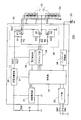
図1は、第1の実施形態に係る車両用灯火装置100の概略的な構成を示すブロック図である。図1に示すように、車両用灯火装置100は、LEDランプユニット10と、インジケータ20と、バッテリBと、イグニッションスイッチSW1と、ハイビームスイッチSWHと、ロービームスイッチSWLと、LEDランプ駆動装置30と、を備える。
図1は、第1の実施形態に係る車両用灯火装置100の概略的な構成を示すブロック図である。図1に示すように、車両用灯火装置100は、LEDランプユニット10と、インジケータ20と、バッテリBと、イグニッションスイッチSW1と、ハイビームスイッチSWHと、ロービームスイッチSWLと、LEDランプ駆動装置30と、を備える。
LEDランプユニット10は、車両のヘッドライトとして機能し、直列接続された第1LEDランプ11及び第2LEDランプ12を含む。第1LEDランプ11と第2LEDランプ12は、それぞれ、直列接続された複数のLED素子を含んでもよく、1つのLED素子を含んでもよい。例えば、第1LEDランプ11はハイビーム用であり、第2LEDランプ12はロービーム用である。第2LEDランプ12は、アノード側端子12aが第1LEDランプ11のカソード側端子11cに接続され、カソード側端子12cが接地されている。LEDランプユニット10は、直列接続された3以上のLEDランプを含んでもよい。
インジケータ20は、車両の使用者(運転者)が目視し易い位置に設けられ、点灯により使用者に異常を知らせる。インジケータ20は、例えば、LED素子を含む。
イグニッションスイッチSW1は、使用者の操作に応じて、バッテリBの電力をLEDランプ駆動装置30に供給するか否か切り替える。
ハイビームスイッチSWHは、一端が接地され、他端がLEDランプ駆動装置30に接続され、使用者の操作に応じて第1LEDランプ11を点灯させるか否か切り替える。
ロービームスイッチSWLは、一端が接地され、他端がLEDランプ駆動装置30に接続され、使用者の操作に応じて第2LEDランプ12を点灯させるか否か切り替える。
LEDランプ駆動装置30は、LEDランプユニット10を駆動する。LEDランプ駆動装置30は、制御電源部31と、I/F(インターフェース)部32と、定電流電源部33と、プリドライブ部34と、切り替え部35と、電圧検出部36と、制御部37と、インジケータ駆動部38と、を備える。
制御電源部31は、イグニッションスイッチSW1の導通時に供給されるバッテリBの電力を用いて、制御電源電圧VCを生成して制御部37に供給する。
I/F部32は、ハイビームスイッチSWHの他端とロービームスイッチSWLの他端とに接続され、ハイビームスイッチSWHとロービームスイッチSWLのそれぞれの状態(導通状態又は非導通状態)を検出する。
定電流電源部33は、LEDランプ駆動電源として機能し、イグニッションスイッチSW1の導通時に供給されるバッテリBの電力を用いて、LEDランプユニット10を駆動するための定電流IOUTを出力する。定電流電源部33は、この定電流IOUTを出力する電流出力端子T1を有する。定電流電源部33の回路方式は、LEDランプユニット10の順方向電圧特性に適合していれば特に限定されず、ドロッパ方式、降圧コンバータ、昇圧コンバータ、昇降圧コンバータ等、どのような回路方式でもよい。
プリドライブ部34は、制御部37の制御に従って切り替え部35を駆動する。
切り替え部35は、定電流電源部33の電流出力端子T1から定電流IOUTが供給され、プリドライブ部34からの駆動信号に応じて、第1LEDランプ11と第2LEDランプ12の少なくとも何れかにこの定電流IOUTを供給する。
具体的には、切り替え部35は、第1LEDランプ11のアノード側端子11aに定電流IOUTを供給する第1状態と、第2LEDランプ12のアノード側端子12aに定電流IOUTを供給する第2状態と、第1LEDランプ11のアノード側端子11aに定電流IOUTを供給し、第1LEDランプ11のカソード側端子11cを接地する第3状態と、を切り替える。
切り替え部35は、第1スイッチング素子Q1と、第2スイッチング素子Q2と、第3スイッチング素子Q3と、抵抗R1~R6と、を有する。図示する例のように、第1及び第2スイッチング素子Q1,Q2は、P型MOSトランジスタであってもよい。第3スイッチング素子Q3は、N型MOSトランジスタであってもよい。
第1スイッチング素子Q1は、電流出力端子T1と第1LEDランプ11のアノード側端子11aとの間に接続されている。抵抗R1は、第1スイッチング素子Q1のソースとゲートとの間に接続されている。抵抗R2は、一端が第1スイッチング素子Q1のゲートに接続され、他端にプリドライブ部34から駆動信号が供給される。
第2スイッチング素子Q2は、電流出力端子T1と第1LEDランプ11のカソード側端子11cとの間に接続されている。抵抗R3は、第2スイッチング素子Q2のソースとゲートとの間に接続されている。抵抗R4は、一端が第2スイッチング素子Q2のゲートに接続され、他端にプリドライブ部34から駆動信号が供給される。
第3スイッチング素子Q3は、第1LEDランプ11のカソード側端子11cと接地との間に接続されている。抵抗R5は、第3スイッチング素子Q3のソースとゲートとの間に接続されている。抵抗R6は、一端が第3スイッチング素子Q3のゲートに接続され、他端にプリドライブ部34から駆動信号が供給される。
電圧検出部36は、電流出力端子T1の出力電圧VOUTを検出する。
制御部37は、例えばマイコンであり、I/F部32における検出結果に応じて、プリドライブ部34を介して切り替え部35を制御する。具体的には、制御部37は、使用者によるハイビームスイッチSWH及びロービームスイッチSWLの操作に応じて、第1状態、第2状態又は第3状態に切り替えるように、切り替え部35を制御する。
また、制御部37は、電圧検出部36で検出された出力電圧VOUTが予め定められた出力電圧範囲から外れた場合、点灯中の第1LEDランプ11又は第2LEDランプ12に異常(断線又は短絡)があると判断し、使用者による操作によらず定電流IOUTの供給先を切り替えるように、切り替え部35を制御する。
出力電圧範囲の最小値は、第1LEDランプ11の順方向電圧より低く、且つ、第2LEDランプ12の順方向電圧より低い。出力電圧範囲の最大値は、第1LEDランプ11の順方向電圧と第2LEDランプ12の順方向電圧との和より高い。
インジケータ駆動部38は、制御部37の制御に応じてインジケータ20を駆動する。制御部37は、出力電圧VOUTが出力電圧範囲から外れた場合、インジケータ駆動部38にインジケータ20を駆動させる。
次に、LEDランプ駆動装置30の動作について、より詳しく説明する。
まず、使用者の操作によりイグニッションスイッチSW1が導通すると、バッテリBの電力が制御電源部31と定電流電源部33とに供給される。これにより、制御電源部31は制御電源電圧VCを生成して制御部37に供給する。制御部37は、この制御電源電圧VCによって動作を開始する。
まず、使用者の操作によりイグニッションスイッチSW1が導通すると、バッテリBの電力が制御電源部31と定電流電源部33とに供給される。これにより、制御電源部31は制御電源電圧VCを生成して制御部37に供給する。制御部37は、この制御電源電圧VCによって動作を開始する。
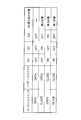
I/F部32は、ハイビームスイッチSWHとロービームスイッチSWLのそれぞれの状態を検出し、検出結果を制御部37に送る。制御部37は、図2に示すように、検出結果に応じて切り替え部35の第1、第2及び第3スイッチング素子Q1,Q2,Q3を切り替える。
ハイビームスイッチSWH及びロービームスイッチSWLが非導通(OPEN)の場合、第1、第2及び第3スイッチング素子Q1,Q2,Q3は導通しない(OFF)。よって、第1LEDランプ11及び第2LEDランプ12は点灯しない。
ハイビームスイッチSWH及びロービームスイッチSWLが導通(CLOSE)している場合、切り替え部35は第1状態に切り替えられる。第1状態において、第1スイッチング素子Q1は導通し(ON)、第2スイッチング素子Q2及び第3スイッチング素子Q3は導通しない。
ハイビームスイッチSWHが非導通であり、ロービームスイッチSWLが導通している場合、切り替え部35は第2状態に切り替えられる。第2状態において、第2スイッチング素子Q2は導通し、第1スイッチング素子Q1及び第3スイッチング素子Q3は導通しない。
ハイビームスイッチSWHが導通し、ロービームスイッチSWLが非導通の場合、切り替え部35は第3状態に切り替えられる。第3状態において、第1スイッチング素子Q1及び第3スイッチング素子Q3は導通し、第2スイッチング素子Q2は導通しない。
また、制御部37は、定電流電源部33に動作開始信号S1を出力する。これにより、定電流電源部33は定電流IOUTを出力する。よって、第1状態では、図3に示すように、第1LEDランプ11及び第2LEDランプ12に定電流IOUTが流れ、ハイビーム及びロービーム点灯となる。
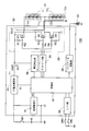
第2状態では、図4に示すように、第2LEDランプ12に定電流IOUTが流れ、第1LEDランプ11に電流が流れず、ロービーム点灯となる。
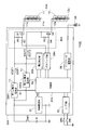
第3状態では、図5に示すように、第1LEDランプ11に定電流IOUTが流れ、第2LEDランプ12に電流が流れず、ハイビーム点灯となる。
ここで、点灯中の第1LEDランプ11又は第2LEDランプ12に断線が発生すると、定電流電源部33の出力電圧VOUTは上昇し、出力電圧範囲から外れるようになる。
また、点灯中の第1LEDランプ11又は第2LEDランプ12に短絡が発生すると、出力電圧VOUTは低下し、出力電圧範囲から外れるようになる。但し、第1LEDランプ11及び第2LEDランプ12に定電流IOUTが流れている第1状態では、一方が短絡しても出力電圧VOUTは出力電圧範囲から外れず、短絡していない他方は点灯し続ける。
制御部37は、第1状態において出力電圧VOUTが出力電圧範囲から外れた場合に、第2状態又は第3状態に切り替え、第2状態において出力電圧VOUTが出力電圧範囲から外れた場合に、第3状態に切り替え、第3状態において出力電圧VOUTが出力電圧範囲から外れた場合に、第2状態に切り替えるように、切り替え部35を制御する。
また、制御部37は、第2状態において出力電圧VOUTが出力電圧範囲から外れ、その後、第3状態において出力電圧VOUTが出力電圧範囲から外れた場合、又は、第3状態において出力電圧VOUTが出力電圧範囲から外れ、その後、第2状態において出力電圧VOUTが出力電圧範囲から外れた場合、定電流電源部33に定電流IOUTの出力を停止させる。
これにより、第1LEDランプ11及び第2LEDランプ12の点灯時(第1状態)に異常が検出されると、ハイビーム用の第1LEDランプ11が点灯される(第3状態)。この時に再び異常が検出されると、ロービーム用の第2LEDランプ12が点灯される(第2状態)。この時に再び異常が検出されると、定電流電源部33は定電流IOUTの出力を停止する。なお、第1LEDランプ11及び第2LEDランプ12の点灯時に異常が検出された時に、先に第2LEDランプ12が点灯されてもよい。
また、ロービーム用の第2LEDランプ12の点灯時(第2状態)に異常が検出されると、ハイビーム用の第1LEDランプ11が点灯する(第3状態)。そして、この時に再び異常が検出されると、定電流電源部33は定電流IOUTの出力を停止する。
また、ハイビーム用の第1LEDランプ11の点灯時(第3状態)に異常が検出されると、ロービーム用の第2LEDランプ12が点灯する(第2状態)。そして、この時に再び異常が検出されると、定電流電源部33は定電流IOUTの出力を停止する。
以上で説明したように、本実施形態によれば、出力電圧VOUTが出力電圧範囲から外れた場合に、定電流IOUTの供給先を切り替えるようにしている。これにより、点灯中の第1LEDランプ11又は第2LEDランプ12に断線又は短絡が発生して出力電圧VOUTが出力電圧範囲から外れた場合に、異常であると判断し、他の第1LEDランプ11又は第2LEDランプ12を点灯させることができる。つまり、他の第1LEDランプ11又は第2LEDランプ12が正常であれば、使用者がハイビームスイッチSWH及びロービームスイッチSWLの操作を行うことなくヘッドライトが全消灯となることを防止することができる。従って、第1LEDランプ11及び第2LEDランプ12の異常に適切に対処できる。
また、第1LEDランプ11及び第2LEDランプ12の両者が異常である場合に、定電流電源部33は定電流IOUTの出力を停止するので、安全性を向上できる。
ところで、上述のように本実施形態では、第1LEDランプ11又は第2LEDランプ12に異常が発生してもヘッドライトとしてのLEDランプユニット10が全消灯しないため、使用者は異常に気付かない可能性がある。しかし、本実施形態によれば、出力電圧VOUTが出力電圧範囲から外れた場合、使用者に視認され易いインジケータ20が点灯するため、使用者は異常に容易に気付くことができる。
(第2の実施形態)
第2の実施形態では、第1LEDランプ11と第2LEDランプ12は直列接続されていない。
第2の実施形態では、第1LEDランプ11と第2LEDランプ12は直列接続されていない。
図6は、第2の実施形態に係る車両用灯火装置100Aの概略的な構成を示すブロック図である。図6では、図1と共通する構成部分には同一の符号を付しており、以下では相違点を中心に説明する。
LEDランプユニット10Aは、第1LEDランプ11及び第2LEDランプ12を含む。第1の実施形態と異なり、第1LEDランプ11は、アノード側端子11aがLEDランプ駆動装置30Aに接続され、カソード側端子11cが接地されている。第2LEDランプ12は、アノード側端子12aがLEDランプ駆動装置30Aに接続され、カソード側端子12cが接地されている。LEDランプユニット10Aは、3以上のLEDランプを含んでもよい。
LEDランプ駆動装置30Aは、制御電源部31と、I/F部32と、第1定電流電源部33A1と、第2定電流電源部33A2と、プリドライブ部34Aと、切り替え部35Aと、電圧検出部36Aと、制御部37Aと、インジケータ駆動部38と、を備える。
第1定電流電源部33A1は、第1定電流IOUT1を出力する第1電流出力端子T1を有する。第1定電流電源部33A1は、制御部37Aからの動作開始信号S1に応じて動作開始する。
第2定電流電源部33A2は、第2定電流IOUT2を出力する第2電流出力端子T2を有する。第2定電流電源部33A2は、制御部37Aからの動作開始信号S2に応じて動作開始する。定電流電源部は、LEDランプの数と同じ数だけ設ければよい。
切り替え部35Aは、第1LEDランプ11に第1定電流IOUT1を供給するか否か切り替え、第2LEDランプ12に第2定電流IOUT2を供給するか否か切り替える。
切り替え部35Aは、第1LEDランプ11のアノード側端子11aに第1定電流IOUT1を供給し、第2LEDランプ12のアノード側端子12aに第2定電流IOUT2を供給する第1状態と、第1LEDランプ11のアノード側端子11aに第1定電流IOUT1を供給せず、第2LEDランプ12のアノード側端子12aに第2定電流IOUT2を供給する第2状態と、第1LEDランプ11のアノード側端子11aに第1定電流IOUT1を供給し、第2LEDランプ12のアノード側端子12aに第2定電流IOUT2を供給しない第3状態と、を切り替える。
切り替え部35Aは、第1スイッチング素子Q1と、第2スイッチング素子Q2と、抵抗R1~R4と、を有する。図示する例のように、第1及び第2スイッチング素子Q1,Q2は、P型MOSトランジスタであってもよい。
第1スイッチング素子Q1は、第1電流出力端子T1と第1LEDランプ11のアノード側端子11aとの間に接続されている。抵抗R1は、第1スイッチング素子Q1のソースとゲートとの間に接続されている。抵抗R2は、一端が第1スイッチング素子Q1のゲートに接続され、他端にプリドライブ部34Aから駆動信号が供給される。
第2スイッチング素子Q2は、第2電流出力端子T2と第2LEDランプ12のアノード側端子12aとの間に接続されている。抵抗R3は、第2スイッチング素子Q2のソースとゲートとの間に接続されている。抵抗R4は、一端が第2スイッチング素子Q2のゲートに接続され、他端にプリドライブ部34Aから駆動信号が供給される。
電圧検出部36Aは、第1電流出力端子T1の第1出力電圧VOUT1及び第2電流出力端子T2の第2出力電圧VOUT2を検出する。
制御部37Aは、第1出力電圧VOUT1が予め定められた第1出力電圧範囲から外れた場合、第2LEDランプ12に第2定電流IOUT2を供給し、第2出力電圧VOUT2が予め定められた第2出力電圧範囲から外れた場合、第1LEDランプ11に第1定電流IOUT1を供給するように、切り替え部35Aを制御する。
第1出力電圧範囲の最小値は、第1LEDランプ11の順方向電圧より低く、第1出力電圧範囲の最大値は、第1LEDランプ11の順方向電圧より高い。
第2出力電圧範囲の最小値は、第2LEDランプ12の順方向電圧より低く、第2出力電圧範囲の最大値は、第2LEDランプ12の順方向電圧より高い。
第1LEDランプ11の順方向電圧と第2LEDランプ12の順方向電圧とがほぼ等しければ、第1出力電圧範囲は第2出力電圧範囲と同じであってもよい。
第2出力電圧範囲の最小値は、第2LEDランプ12の順方向電圧より低く、第2出力電圧範囲の最大値は、第2LEDランプ12の順方向電圧より高い。
第1LEDランプ11の順方向電圧と第2LEDランプ12の順方向電圧とがほぼ等しければ、第1出力電圧範囲は第2出力電圧範囲と同じであってもよい。
制御部37Aは、使用者による操作に応じて、第1状態、第2状態又は第3状態を切り替えるように、切り替え部35Aを制御する。
具体的には、制御部37Aは、図7に示すように、ハイビームスイッチSWHとロービームスイッチSWLのそれぞれの状態に応じて、切り替え部35Aの第1及び第2スイッチング素子Q1,Q2を切り替える。
ハイビームスイッチSWH及びロービームスイッチSWLが非導通の場合、第1及び第2スイッチング素子Q1,Q2は導通しない。よって、第1LEDランプ11及び第2LEDランプ12は点灯しない。
ハイビームスイッチSWH及びロービームスイッチSWLが導通している場合、切り替え部35Aは第1状態に切り替えられる。第1状態において、第1及び第2スイッチング素子Q1,Q2は導通する。よって、第1LEDランプ11に第1定電流IOUT1が流れ、第2LEDランプ12に第2定電流IOUT2が流れ、ハイビーム及びロービーム点灯となる。
ハイビームスイッチSWHが非導通であり、ロービームスイッチSWLが導通している場合、切り替え部35Aは第2状態に切り替えられる。第2状態において、第2スイッチング素子Q2は導通し、第1スイッチング素子Q1は導通しない。よって、第2LEDランプ12に第2定電流IOUT2が流れ、第1LEDランプ11に電流が流れず、ロービーム点灯となる。
ハイビームスイッチSWHが導通し、ロービームスイッチSWLが非導通の場合、切り替え部35Aは第3状態に切り替えられる。第3状態において、第1スイッチング素子Q1は導通し、第2スイッチング素子Q2は導通しない。よって、第1LEDランプ11に第1定電流IOUT1が流れ、第2LEDランプ12に電流が流れず、ハイビーム点灯となる。
ここで、点灯中の第1LEDランプ11に断線が発生すると、第1出力電圧VOUT1は上昇し、第1出力電圧範囲から外れるようになる。点灯中の第2LEDランプ12に断線が発生すると、第2出力電圧VOUT2は上昇し、第2出力電圧範囲から外れるようになる。
また、点灯中の第1LEDランプ11に短絡が発生すると、第1出力電圧VOUT1は低下し、第1出力電圧範囲から外れるようになる。点灯中の第2LEDランプ12に短絡が発生すると、第2出力電圧VOUT2は低下し、第2出力電圧範囲から外れるようになる。
制御部37Aは、第1出力電圧VOUT1が第1出力電圧範囲から外れた場合、使用者による操作によらず第2状態に切り替え、第2出力電圧VOUT2が第2出力電圧範囲から外れた場合、使用者による操作によらず第3状態に切り替えるように、切り替え部35Aを制御する。
また、制御部37Aは、第1出力電圧VOUT1が第1出力電圧範囲から外れ、その後、第2出力電圧VOUT2が第2出力電圧範囲から外れた場合、又は、第2出力電圧VOUT2が第2出力電圧範囲から外れ、その後、第1出力電圧VOUT1が第1出力電圧範囲から外れた場合、第1定電流電源部33A1及び第2定電流電源部33A2に第1定電流IOUT1及び第2定電流IOUT2の出力を停止させる。
これにより、第1LEDランプ11及び第2LEDランプ12の点灯時(第1状態)に第1出力電圧VOUT1に異常が検出されると、ロービーム用の第2LEDランプ12のみが点灯される(第2状態)。この時に再び異常が検出されると、第1定電流電源部33A1及び第2定電流電源部33A2は第1定電流IOUT1及び第2定電流IOUT2の出力を停止する。
また、第1LEDランプ11及び第2LEDランプ12の点灯時(第1状態)に第2出力電圧VOUT2に異常が検出されると、ハイビーム用の第1LEDランプ11のみが点灯される(第3状態)。この時に再び異常が検出されると、第1定電流電源部33A1及び第2定電流電源部33A2は第1定電流IOUT1及び第2定電流IOUT2の出力を停止する。
また、使用者の操作によるロービーム用の第2LEDランプ12の点灯時(第2状態)に異常が検出されると、ハイビーム用の第1LEDランプ11が点灯する(第3状態)。そして、この時に再び異常が検出されると、第1定電流電源部33A1及び第2定電流電源部33A2は第1定電流IOUT1及び第2定電流IOUT2の出力を停止する。
さらに、使用者の操作によるハイビーム用の第1LEDランプ11の点灯時(第3状態)に異常が検出されると、ロービーム用の第2LEDランプ12が点灯する(第2状態)。そして、この時に再び異常が検出されると、第1定電流電源部33A1及び第2定電流電源部33A2は第1定電流IOUT1及び第2定電流IOUT2の出力を停止する。
制御部37Aは、第1出力電圧VOUT1が第1出力電圧範囲から外れた場合、又は、第2出力電圧VOUT2が第2出力電圧範囲から外れた場合、インジケータ駆動部38にインジケータ20を駆動させる。
以上で説明したように、本実施形態によれば、第1出力電圧VOUT1が第1出力電圧範囲から外れた場合、第2LEDランプ12に第2定電流IOUT2を供給し、第2出力電圧VOUT2が第2出力電圧範囲から外れた場合、第1LEDランプ11に第1定電流IOUT1を供給するようにしている。これにより、点灯中の第1LEDランプ11又は第2LEDランプ12に断線又は短絡が発生した場合に、異常であると判断し、他の第1LEDランプ11又は第2LEDランプ12を点灯させることができる。従って、第1LEDランプ11及び第2LEDランプ12の異常に適切に対処できる。また、第1の実施形態の他の効果も得られる。
加えて、第1の実施形態と異なり、第1LEDランプ11と第2LEDランプ12が直列接続されていないので、第1及び第2定電流電源部33A1,33A2は、第1の実施形態よりも低い第1及び第2出力電圧VOUT1,VOUT2に対応できればよい。
(第3の実施形態)
第3の実施形態では、第1の実施形態の車両用灯火装置100を方向指示装置として構成している。
第3の実施形態では、第1の実施形態の車両用灯火装置100を方向指示装置として構成している。
図8は、第3の実施形態に係る車両用灯火装置(方向指示装置)100Bの概略的な構成を示すブロック図である。図8では、図1と共通する構成部分には同一の符号を付しており、以下では相違点を中心に説明する。
車両用灯火装置100Bは、方向指示灯として機能する右側用のLEDランプユニット10Rと左側用のLEDランプユニット10Lとを有する。LEDランプ駆動装置30Bは、LEDランプユニット10RとLEDランプユニット10Lの少なくとも何れかを駆動する。
各LEDランプユニット10R,10Lは、第1の実施形態のLEDランプユニット10の構成に加え、第1LEDランプ11と第2LEDランプ12とに直列接続された第3LEDランプ13を更に含む。第3LEDランプ13は、カソード側端子13cが第1LEDランプ11のアノード側端子11aに接続されている。各LEDランプユニット10R,10Lは、直列接続された4以上のLEDランプを含んでもよい。
切り替え部35Bは、プリドライブ部34Bからの駆動信号に応じて、LEDランプユニット10R又は10Lにおける第1LEDランプ11、第2LEDランプ12及び第3LEDランプ13の少なくとも何れかに定電流IOUTを供給する。切り替え部35Bの具体的な構成の図示は省略するが、例えば、第1の実施形態と同様に複数のスイッチング素子を用いた構成とすることができる。
制御部37Bは、使用者の操作によって右側用の方向指示スイッチR-SWが導通した場合、選択されたLEDランプユニット10Rを点滅させ、左側用の方向指示スイッチL-SWが導通した場合、選択されたLEDランプユニット10Lを点滅させるように、プリドライブ部34Bを介して切り替え部35Bを制御する。
制御部37Bは、選択されたLEDランプユニット10R又は10Lにおいて、繰り返し、第1LEDランプ11、第2LEDランプ12及び第3LEDランプ13に1つずつ順番に定電流IOUTを供給するように、切り替え部35Bを制御する。これにより、選択されたLEDランプユニット10R又は10Lにおいて、第1LEDランプ11が一定期間だけ点灯し、その後、第2LEDランプ12が一定期間だけ点灯し、その後、第3LEDランプ13が一定期間だけ点灯する動作を繰り返す。従って、LEDランプユニット10R,10Lは、いわゆる「流れるウィンカー」として点滅動作する。
ここで、点灯中の第1LEDランプ11、第2LEDランプ12又は第3LEDランプ13に断線が発生すると、出力電圧VOUTは上昇し、出力電圧範囲から外れるようになる。また、点灯中の第1LEDランプ11、第2LEDランプ12又は第3LEDランプ13に短絡が発生すると、出力電圧VOUTは低下し、出力電圧範囲から外れるようになる。
制御部37Bは、出力電圧VOUTが出力電圧範囲から外れた場合、第1LEDランプ11、第2LEDランプ12及び第3LEDランプ13のうちの2つに定電流IOUTを間欠的に供給するように、切り替え部35Bを制御する。具体的には、制御部37は、出力電圧VOUTが出力電圧範囲から外れた時に定電流IOUTが供給されていた第1LEDランプ11、第2LEDランプ12又は第3LEDランプ13以外の2つのLEDランプに定電流IOUTを間欠的に供給するように、切り替え部35Bを制御する。
これにより、異常が発生していない2つのLEDランプを同時に点滅させることができる。
「流れるウィンカー」として動作しているLEDランプユニット10R又は10Lにおいて、第1から第3LEDランプ11~13のうちの何れかが点灯しないようになると、流れるような点灯動作が途中で途切れるように視認されるため、周囲の車両の運転者等が驚く可能性がある。
これに対して、本実施形態によれば、第1LEDランプ11、第2LEDランプ12又は第3LEDランプ13に異常が発生した場合には、LEDランプユニット10R又は10Lは、「流れるウィンカー」としての動作を停止して、周知のウィンカーと同じ点滅動作を行う。そのため、第1から第3LEDランプ11~13のうちの何れかが点灯しなくとも、周囲の車両の運転者等が驚き難くなる。従って、第1LEDランプ11、第2LEDランプ12又は第3LEDランプ13の異常に適切に対処できる。
なお、使用者の操作によって方向指示スイッチR-SW,L-SWの両方が導通した場合に、ハザード動作として2つのLEDランプユニット10R,10Lを同時に点滅動作させてもよい。
(第4の実施形態)
第4の実施形態では、第2の実施形態の車両用灯火装置100Aを方向指示装置として構成している。
第4の実施形態では、第2の実施形態の車両用灯火装置100Aを方向指示装置として構成している。
図9は、第4の実施形態に係る車両用灯火装置(方向指示装置)100Cの概略的な構成を示すブロック図である。図9では、図6と共通する構成部分には同一の符号を付しており、以下では相違点を中心に説明する。
車両用灯火装置100Cは、方向指示灯として機能する右側用のLEDランプユニット10ARと左側用のLEDランプユニット10ALとを有する。
各LEDランプユニット10AR,10ALは、第2の実施形態のLEDランプユニット10Aの構成に加え、第3LEDランプ13を更に含む。第3LEDランプ13は、アノード側端子13aがLEDランプ駆動装置30Cに接続され、カソード側端子13cが接地されている。各LEDランプユニット10AR,10ALは、4つ以上のLEDランプを含んでもよい。
LEDランプ駆動装置30Cは、第3定電流IOUT3を出力する第3電流出力端子T3を有する第3定電流電源部33A3を更に備える。第3定電流電源部33A3は、制御部37Cからの動作開始信号S3に応じて動作開始する。定電流電源部は、LEDランプの数と同じ数だけ設ければよい。
切り替え部35Cは、プリドライブ部34Cからの駆動信号に応じて、LEDランプユニット10R又は10Lにおいて、第1LEDランプ11に第1定電流IOUT1を供給するか否か切り替え、第2LEDランプ12に第2定電流IOUT2を供給するか否か切り替え、第3LEDランプ13に第3定電流IOUT3を供給するか否か切り替える。切り替え部35Cは、例えば、第2の実施形態の構成に加え、スイッチング素子Q3~Q6を更に備えた構成とすることができる。なお、図9では、明確化のためにスイッチング素子Q1~Q6をスイッチの記号で示しているが、スイッチング素子Q1~Q6は、第2の実施形態と同様にトランジスタで構成することができる。
電圧検出部36Cは、第2の実施形態の機能に加え、第3電流出力端子T3の第3出力電圧VOUT3を検出する。
制御部37Cは、使用者により操作された方向指示スイッチR-SW,L-SWの状態に応じて、選択されたLEDランプユニット10AR又は10ALを点滅させるように、プリドライブ部34Cを介して切り替え部35Cを制御する。
制御部37Cは、選択されたLEDランプユニット10AR又は10ALにおいて、繰り返し、第1、第2及び第3LEDランプ11,12,13に1つずつ順番に第1、第2又は第3定電流IOUT1,IOUT2,IOUT3を供給するように、切り替え部35Cを制御する。これにより、第3の実施形態と同様に、LEDランプユニット10AR,10ALは、「流れるウィンカー」として点滅動作する。
制御部37Cは、第1出力電圧VOUT1が第1出力電圧範囲から外れた場合、第2及び第3LEDランプ12,13に第2及び第3定電流IOUT2,IOUT3を間欠的に供給するように、切り替え部35Cを制御する。
制御部37Cは、第2出力電圧VOUT2が第2出力電圧範囲から外れた場合、第1及び第3LEDランプ11,13に第1及び第3定電流IOUT1,IOUT3を間欠的に供給するように、切り替え部35Cを制御する。
制御部37Cは、第3出力電圧VOUT3が予め定められた第3出力電圧範囲から外れた場合、第1及び第2LEDランプ11,12に第1及び第2定電流IOUT1,IOUT2を間欠的に供給するように、切り替え部35Cを制御する。
これにより、第1、第2又は第3LEDランプ11,12,13に異常が発生した場合には、「流れるウィンカー」としての動作を停止して、異常が発生していないLEDランプを同時に点滅させることができる。
従って、第3の実施形態と同様の効果が得られる。
従って、第3の実施形態と同様の効果が得られる。
本実施形態においても、使用者の操作に応じて、ハザード動作として2つのLEDランプユニット10AR,10ALを同時に点滅動作させるように構成してもよい。
本発明の態様は、上述した個々の実施形態に限定されるものではなく、当業者が想到しうる種々の変形も含むものであり、本発明の効果も上述した内容に限定されない。すなわち、特許請求の範囲に規定された内容およびその均等物から導き出される本発明の概念的な思想と趣旨を逸脱しない範囲で種々の追加、変更および部分的削除が可能である。
10,10A,10L,10R,10AL,10AR LEDランプユニット
11 第1LEDランプ
12 第2LEDランプ
13 第3LEDランプ
20 インジケータ
B バッテリ
SW1 イグニッションスイッチ
SWH ハイビームスイッチ
SWL ロービームスイッチ
R-SW,L-SW 方向指示スイッチ
30,30A,30B,30C LEDランプ駆動装置
31 制御電源部
32 I/F部
33 定電流電源部
33A1 第1定電流電源部
33A2 第2定電流電源部
33A3 第3定電流電源部
T1 電流出力端子、第1電流出力端子
T2 第2電流出力端子
T3 第3電流出力端子
34,34A,34B,34C プリドライブ部
35,35A,35B,35C 切り替え部
Q1 第1スイッチング素子
Q2 第2スイッチング素子
Q3 第3スイッチング素子
36,36A,36C 電圧検出部
37,37A,37B,37C 制御部
38 インジケータ駆動部
100,100A,100B,100C 車両用灯火装置
11 第1LEDランプ
12 第2LEDランプ
13 第3LEDランプ
20 インジケータ
B バッテリ
SW1 イグニッションスイッチ
SWH ハイビームスイッチ
SWL ロービームスイッチ
R-SW,L-SW 方向指示スイッチ
30,30A,30B,30C LEDランプ駆動装置
31 制御電源部
32 I/F部
33 定電流電源部
33A1 第1定電流電源部
33A2 第2定電流電源部
33A3 第3定電流電源部
T1 電流出力端子、第1電流出力端子
T2 第2電流出力端子
T3 第3電流出力端子
34,34A,34B,34C プリドライブ部
35,35A,35B,35C 切り替え部
Q1 第1スイッチング素子
Q2 第2スイッチング素子
Q3 第3スイッチング素子
36,36A,36C 電圧検出部
37,37A,37B,37C 制御部
38 インジケータ駆動部
100,100A,100B,100C 車両用灯火装置
Claims (14)
- 直列接続された第1LEDランプ及び第2LEDランプを含むLEDランプユニットを駆動するLEDランプ駆動装置であって、
定電流を出力する電流出力端子を有する定電流電源部と、
前記第1LEDランプと前記第2LEDランプの少なくとも何れかに前記定電流を供給する切り替え部と、
前記電流出力端子の出力電圧を検出する電圧検出部と、
前記出力電圧が予め定められた出力電圧範囲から外れた場合、前記定電流の供給先を切り替えるように前記切り替え部を制御する制御部と、を備える、
ことを特徴とするLEDランプ駆動装置。 - 前記出力電圧範囲の最小値は、前記第1LEDランプの順方向電圧より低く、且つ、前記第2LEDランプの順方向電圧より低く、
前記出力電圧範囲の最大値は、前記第1LEDランプの順方向電圧と前記第2LEDランプの順方向電圧との和より高い、ことを特徴とする請求項1に記載のLEDランプ駆動装置。 - 前記第2LEDランプは、アノード側端子が前記第1LEDランプのカソード側端子に接続され、カソード側端子が接地され、
前記切り替え部は、前記第1LEDランプのアノード側端子に前記定電流を供給する第1状態と、前記第2LEDランプのアノード側端子に前記定電流を供給する第2状態と、前記第1LEDランプのアノード側端子に前記定電流を供給し、前記第1LEDランプのカソード側端子を接地する第3状態と、を切り替え、
前記制御部は、使用者による操作に応じて、前記第1状態、前記第2状態又は前記第3状態に切り替え、前記出力電圧が前記出力電圧範囲から外れた場合、前記使用者による操作によらず前記定電流の供給先を切り替えるように、前記切り替え部を制御する、ことを特徴とする請求項1に記載のLEDランプ駆動装置。 - 前記切り替え部は、
前記電流出力端子と前記第1LEDランプのアノード側端子との間に接続された第1スイッチング素子と、
前記電流出力端子と前記第1LEDランプのカソード側端子との間に接続された第2スイッチング素子と、
前記第1LEDランプのカソード側端子と接地との間に接続された第3スイッチング素子と、を有し、
前記第1状態において、前記第1スイッチング素子は導通し、前記第2スイッチング素子及び前記第3スイッチング素子は導通せず、
前記第2状態において、前記第2スイッチング素子は導通し、前記第1スイッチング素子及び前記第3スイッチング素子は導通せず、
前記第3状態において、前記第1スイッチング素子及び前記第3スイッチング素子は導通し、前記第2スイッチング素子は導通しない、ことを特徴とする請求項3に記載のLEDランプ駆動装置。 - 前記制御部は、前記第1状態において前記出力電圧が前記出力電圧範囲から外れた場合に、前記第2状態又は前記第3状態に切り替え、前記第2状態において前記出力電圧が前記出力電圧範囲から外れた場合に、前記第3状態に切り替え、前記第3状態において前記出力電圧が前記出力電圧範囲から外れた場合に、前記第2状態に切り替えるように、前記切り替え部を制御する、ことを特徴とする請求項3に記載のLEDランプ駆動装置。
- 前記制御部は、前記第2状態において前記出力電圧が前記出力電圧範囲から外れ、その後、前記第3状態において前記出力電圧が前記出力電圧範囲から外れた場合、又は、前記第3状態において前記出力電圧が前記出力電圧範囲から外れ、その後、前記第2状態において前記出力電圧が前記出力電圧範囲から外れた場合、前記定電流電源部に前記定電流の出力を停止させる、ことを特徴とする請求項5に記載のLEDランプ駆動装置。
- インジケータを駆動するインジケータ駆動部を更に備え、
前記制御部は、前記出力電圧が前記出力電圧範囲から外れた場合、前記インジケータ駆動部に前記インジケータを駆動させる、ことを特徴とする請求項1に記載のLEDランプ駆動装置。 - 前記LEDランプユニットは、前記第1LEDランプと前記第2LEDランプとに直列接続された第3LEDランプを更に含み、
前記切り替え部は、前記第1LEDランプ、前記第2LEDランプ及び前記第3LEDランプの少なくとも何れかに前記定電流を供給し、
前記制御部は、繰り返し、前記第1LEDランプ、前記第2LEDランプ及び前記第3LEDランプに1つずつ順番に前記定電流を供給し、前記出力電圧が前記出力電圧範囲から外れた場合、前記第1LEDランプ、前記第2LEDランプ及び前記第3LEDランプのうちの2つに前記定電流を間欠的に供給するように、前記切り替え部を制御する、ことを特徴とする請求項1に記載のLEDランプ駆動装置。 - 第1LEDランプ及び第2LEDランプを含むLEDランプユニットを駆動するLEDランプ駆動装置であって、
第1定電流を出力する第1電流出力端子を有する第1定電流電源部と、
第2定電流を出力する第2電流出力端子を有する第2定電流電源部と、
前記第1LEDランプに前記第1定電流を供給するか否か切り替え、前記第2LEDランプに前記第2定電流を供給するか否か切り替える切り替え部と、
前記第1電流出力端子の第1出力電圧及び前記第2電流出力端子の第2出力電圧を検出する電圧検出部と、
前記第1出力電圧が予め定められた第1出力電圧範囲から外れた場合、前記第2LEDランプに前記第2定電流を供給し、前記第2出力電圧が予め定められた第2出力電圧範囲から外れた場合、前記第1LEDランプに前記第1定電流を供給するように、前記切り替え部を制御する制御部と、を備える、
ことを特徴とするLEDランプ駆動装置。 - 前記第1出力電圧範囲の最小値は、前記第1LEDランプの順方向電圧より低く、
前記第1出力電圧範囲の最大値は、前記第1LEDランプの順方向電圧より高く、
前記第2出力電圧範囲の最小値は、前記第2LEDランプの順方向電圧より低く、
前記第2出力電圧範囲の最大値は、前記第2LEDランプの順方向電圧より高い、ことを特徴とする請求項9に記載のLEDランプ駆動装置。 - 前記切り替え部は、
前記第1LEDランプのアノード側端子に前記第1定電流を供給し、前記第2LEDランプのアノード側端子に前記第2定電流を供給する第1状態と、
前記第1LEDランプのアノード側端子に前記第1定電流を供給せず、前記第2LEDランプのアノード側端子に前記第2定電流を供給する第2状態と、
前記第1LEDランプのアノード側端子に前記第1定電流を供給し、前記第2LEDランプのアノード側端子に前記第2定電流を供給しない第3状態と、を切り替え、
前記制御部は、使用者による操作に応じて、前記第1状態、前記第2状態又は前記第3状態を切り替え、前記第1出力電圧が前記第1出力電圧範囲から外れた場合、前記使用者による操作によらず前記第2状態に切り替え、前記第2出力電圧が前記第2出力電圧範囲から外れた場合、前記使用者による操作によらず前記第3状態に切り替えるように、前記切り替え部を制御する、ことを特徴とする請求項9に記載のLEDランプ駆動装置。 - 前記制御部は、前記第1出力電圧が前記第1出力電圧範囲から外れ、その後、前記第2出力電圧が前記第2出力電圧範囲から外れた場合、又は、前記第2出力電圧が前記第2出力電圧範囲から外れ、その後、前記第1出力電圧が前記第1出力電圧範囲から外れた場合、前記第1定電流電源部及び前記第2定電流電源部に前記第1定電流及び前記第2定電流の出力を停止させる、ことを特徴とする請求項11に記載のLEDランプ駆動装置。
- インジケータを駆動するインジケータ駆動部を更に備え、
前記制御部は、前記第1出力電圧が前記第1出力電圧範囲から外れた場合、又は、前記第2出力電圧が前記第2出力電圧範囲から外れた場合、前記インジケータ駆動部に前記インジケータを駆動させる、ことを特徴とする請求項9に記載のLEDランプ駆動装置。 - 第3定電流を出力する第3電流出力端子を有する第3定電流電源部を更に備え、
前記LEDランプユニットは、第3LEDランプを更に含み、
前記切り替え部は、前記第3LEDランプに前記第3定電流を供給するか否か切り替え、
前記電圧検出部は、前記第3電流出力端子の第3出力電圧を検出し、
前記制御部は、繰り返し、前記第1、第2及び第3LEDランプに1つずつ順番に前記第1、第2又は第3定電流を供給し、前記第1出力電圧が前記第1出力電圧範囲から外れた場合、前記第2及び第3LEDランプに前記第2及び第3定電流を間欠的に供給し、前記第2出力電圧が前記第2出力電圧範囲から外れた場合、前記第1及び第3LEDランプに前記第1及び第3定電流を間欠的に供給し、前記第3出力電圧が予め定められた第3出力電圧範囲から外れた場合、前記第1及び第2LEDランプに前記第1及び第2定電流を間欠的に供給するように、前記切り替え部を制御する、ことを特徴とする請求項9に記載のLEDランプ駆動装置。
Priority Applications (2)
| Application Number | Priority Date | Filing Date | Title |
|---|---|---|---|
| JP2016568250A JP6271041B2 (ja) | 2015-01-09 | 2015-01-09 | Ledランプ駆動装置 |
| PCT/JP2015/050518 WO2016111008A1 (ja) | 2015-01-09 | 2015-01-09 | Ledランプ駆動装置 |
Applications Claiming Priority (1)
| Application Number | Priority Date | Filing Date | Title |
|---|---|---|---|
| PCT/JP2015/050518 WO2016111008A1 (ja) | 2015-01-09 | 2015-01-09 | Ledランプ駆動装置 |
Publications (1)
| Publication Number | Publication Date |
|---|---|
| WO2016111008A1 true WO2016111008A1 (ja) | 2016-07-14 |
Family
ID=56355728
Family Applications (1)
| Application Number | Title | Priority Date | Filing Date |
|---|---|---|---|
| PCT/JP2015/050518 Ceased WO2016111008A1 (ja) | 2015-01-09 | 2015-01-09 | Ledランプ駆動装置 |
Country Status (2)
| Country | Link |
|---|---|
| JP (1) | JP6271041B2 (ja) |
| WO (1) | WO2016111008A1 (ja) |
Cited By (1)
| Publication number | Priority date | Publication date | Assignee | Title |
|---|---|---|---|---|
| KR20180100077A (ko) * | 2017-01-30 | 2018-09-07 | 신덴겐코교 가부시키가이샤 | Led용 제어 장치, 및, led용 제어 장치의 제어 방법 |
Families Citing this family (1)
| Publication number | Priority date | Publication date | Assignee | Title |
|---|---|---|---|---|
| CN109839604A (zh) * | 2017-11-28 | 2019-06-04 | 小丝电工株式会社 | 断芯检测电路以及电源装置 |
Citations (6)
| Publication number | Priority date | Publication date | Assignee | Title |
|---|---|---|---|---|
| JP2010030500A (ja) * | 2008-07-30 | 2010-02-12 | Denso Corp | オートライトシステム |
| JP2011054964A (ja) * | 2009-09-01 | 2011-03-17 | Samsung Electronics Co Ltd | Led駆動装置及び方法、これを利用するled駆動システム及び液晶表示装置 |
| JP2012004240A (ja) * | 2010-06-15 | 2012-01-05 | Mitsubishi Electric Corp | Led電源装置及びled照明器具 |
| CN102695317A (zh) * | 2011-03-22 | 2012-09-26 | 青岛海信电器股份有限公司 | 确保光源模组正常工作的电路、方法 |
| JP2013084557A (ja) * | 2011-07-21 | 2013-05-09 | Rohm Co Ltd | 照明装置 |
| JP2013235848A (ja) * | 2013-07-23 | 2013-11-21 | Mitsubishi Electric Corp | 点灯装置及び照明装置 |
Family Cites Families (3)
| Publication number | Priority date | Publication date | Assignee | Title |
|---|---|---|---|---|
| JP2009241665A (ja) * | 2008-03-29 | 2009-10-22 | Shindengen Electric Mfg Co Ltd | ランプ駆動装置およびプログラム |
| JP5771775B2 (ja) * | 2010-12-21 | 2015-09-02 | パナソニックIpマネジメント株式会社 | 点灯装置および、これを用いた灯具,車両 |
| JP5749244B2 (ja) * | 2012-12-19 | 2015-07-15 | 新電元工業株式会社 | Ledランプ点灯装置、及び制御方法 |
-
2015
- 2015-01-09 JP JP2016568250A patent/JP6271041B2/ja active Active
- 2015-01-09 WO PCT/JP2015/050518 patent/WO2016111008A1/ja not_active Ceased
Patent Citations (6)
| Publication number | Priority date | Publication date | Assignee | Title |
|---|---|---|---|---|
| JP2010030500A (ja) * | 2008-07-30 | 2010-02-12 | Denso Corp | オートライトシステム |
| JP2011054964A (ja) * | 2009-09-01 | 2011-03-17 | Samsung Electronics Co Ltd | Led駆動装置及び方法、これを利用するled駆動システム及び液晶表示装置 |
| JP2012004240A (ja) * | 2010-06-15 | 2012-01-05 | Mitsubishi Electric Corp | Led電源装置及びled照明器具 |
| CN102695317A (zh) * | 2011-03-22 | 2012-09-26 | 青岛海信电器股份有限公司 | 确保光源模组正常工作的电路、方法 |
| JP2013084557A (ja) * | 2011-07-21 | 2013-05-09 | Rohm Co Ltd | 照明装置 |
| JP2013235848A (ja) * | 2013-07-23 | 2013-11-21 | Mitsubishi Electric Corp | 点灯装置及び照明装置 |
Cited By (4)
| Publication number | Priority date | Publication date | Assignee | Title |
|---|---|---|---|---|
| KR20180100077A (ko) * | 2017-01-30 | 2018-09-07 | 신덴겐코교 가부시키가이샤 | Led용 제어 장치, 및, led용 제어 장치의 제어 방법 |
| CN108668525A (zh) * | 2017-01-30 | 2018-10-16 | 新电元工业株式会社 | Led用控制装置、以及led用控制装置的制造方法 |
| US10212772B2 (en) | 2017-01-30 | 2019-02-19 | Shindengen Electric Manufacturing Co., Ltd. | LED control device and control method of LED control device |
| KR101965993B1 (ko) * | 2017-01-30 | 2019-04-04 | 신덴겐코교 가부시키가이샤 | Led용 제어 장치, 및, led용 제어 장치의 제어 방법 |
Also Published As
| Publication number | Publication date |
|---|---|
| JPWO2016111008A1 (ja) | 2017-09-21 |
| JP6271041B2 (ja) | 2018-01-31 |
Similar Documents
| Publication | Publication Date | Title |
|---|---|---|
| US9992835B2 (en) | Lighting circuit | |
| EP3468303B1 (en) | A led lamp having an outage detection circuit | |
| JP4907078B2 (ja) | 発光ダイオード用電気供給装置および同装置を有するランプ | |
| CN107734738B (zh) | 点亮电路及车辆用灯具 | |
| JP2006073400A (ja) | 車両用灯具の点灯制御回路 | |
| JP6821835B2 (ja) | 点灯回路およびそれを用いた車両用灯具 | |
| JP6275878B2 (ja) | Ledランプ駆動装置 | |
| JP5715987B2 (ja) | Led故障検出装置 | |
| CN112566817A (zh) | 点亮电路及车辆用灯具 | |
| JP6271041B2 (ja) | Ledランプ駆動装置 | |
| JP4459147B2 (ja) | 車両用灯体の故障検出装置及び灯体ユニット | |
| JP2008168706A (ja) | 光源ユニット群点灯装置 | |
| JP5187756B2 (ja) | 車両用灯具の発光装置 | |
| CN114258173B (zh) | 车辆用灯具系统 | |
| JP2013109939A (ja) | 半導体光源点灯回路 | |
| JP7158835B2 (ja) | 車両用制御装置および車両用制御装置の制御方法 | |
| CN114982379A (zh) | 点亮电路以及车辆用方向指示灯 | |
| JP7643992B2 (ja) | 点灯回路、及び車両用灯具 | |
| JP2011073509A (ja) | 車載ランプ点灯制御回路 | |
| JP2018122637A (ja) | 車両用ターンシグナルランプ断線検出装置 | |
| JP2005153706A (ja) | 車両用ランプ制御装置 | |
| JP2011255729A (ja) | 点灯制御回路及び車両用灯具システム | |
| KR101349047B1 (ko) | 차량용 엘이디 구동회로 | |
| JP2002144958A (ja) | 車両用ランプの点灯制御装置 | |
| WO2018235127A1 (ja) | 車載用照明装置 |
Legal Events
| Date | Code | Title | Description |
|---|---|---|---|
| 121 | Ep: the epo has been informed by wipo that ep was designated in this application |
Ref document number: 15876883 Country of ref document: EP Kind code of ref document: A1 |
|
| ENP | Entry into the national phase |
Ref document number: 2016568250 Country of ref document: JP Kind code of ref document: A |
|
| NENP | Non-entry into the national phase |
Ref country code: DE |
|
| 122 | Ep: pct application non-entry in european phase |
Ref document number: 15876883 Country of ref document: EP Kind code of ref document: A1 |