WO2016111000A1 - 回路遮断器 - Google Patents
回路遮断器 Download PDFInfo
- Publication number
- WO2016111000A1 WO2016111000A1 PCT/JP2015/050470 JP2015050470W WO2016111000A1 WO 2016111000 A1 WO2016111000 A1 WO 2016111000A1 JP 2015050470 W JP2015050470 W JP 2015050470W WO 2016111000 A1 WO2016111000 A1 WO 2016111000A1
- Authority
- WO
- WIPO (PCT)
- Prior art keywords
- trip bar
- trip
- circuit breaker
- spring
- state
- Prior art date
Links
Images


Classifications
-
- H—ELECTRICITY
- H01—ELECTRIC ELEMENTS
- H01H—ELECTRIC SWITCHES; RELAYS; SELECTORS; EMERGENCY PROTECTIVE DEVICES
- H01H71/00—Details of the protective switches or relays covered by groups H01H73/00 - H01H83/00
- H01H71/10—Operating or release mechanisms
- H01H71/50—Manual reset mechanisms which may be also used for manual release
- H01H71/505—Latching devices between operating and release mechanism
-
- H—ELECTRICITY
- H01—ELECTRIC ELEMENTS
- H01H—ELECTRIC SWITCHES; RELAYS; SELECTORS; EMERGENCY PROTECTIVE DEVICES
- H01H71/00—Details of the protective switches or relays covered by groups H01H73/00 - H01H83/00
- H01H71/10—Operating or release mechanisms
- H01H71/12—Automatic release mechanisms with or without manual release
- H01H71/123—Automatic release mechanisms with or without manual release using a solid-state trip unit
-
- H—ELECTRICITY
- H01—ELECTRIC ELEMENTS
- H01H—ELECTRIC SWITCHES; RELAYS; SELECTORS; EMERGENCY PROTECTIVE DEVICES
- H01H71/00—Details of the protective switches or relays covered by groups H01H73/00 - H01H83/00
- H01H71/10—Operating or release mechanisms
- H01H71/50—Manual reset mechanisms which may be also used for manual release
- H01H71/52—Manual reset mechanisms which may be also used for manual release actuated by lever
- H01H71/522—Manual reset mechanisms which may be also used for manual release actuated by lever comprising a cradle-mechanism
- H01H71/525—Manual reset mechanisms which may be also used for manual release actuated by lever comprising a cradle-mechanism comprising a toggle between cradle and contact arm and mechanism spring acting between handle and toggle knee
Definitions
- This invention relates to a circuit breaker, and more particularly to the relative structure of its trip bar and trip bar spring.
- the trip mechanism When an overcurrent flows in the circuit breaker, the trip mechanism will reliably trip without interfering with the tripping load of the trip device, and when the tripped breaker is turned on again. It is necessary to perform the reset operation without fail.
- the trip bar is biased by one end of a trip bar spring (twist spring), and the latch is biased by the other end of the trip bar spring.
- the trip bar when resetting the tripped circuit breaker, the trip bar is characterized by returning the trip bar from the trip position to the reset position only by the force of the trip bar spring.
- the trip bar and trip bar spring structure of the above structure only a substantially constant spring moment can be obtained regardless of the trip bar operating position, and the operating angle itself is small, so when shifting from the trip state to the reset state,
- the present invention has been made to solve the above-described problems, and can increase the trip bar return force at the time of resetting without increasing the operating load of the trip bar required at the time of tripping. And it aims at obtaining the structure of a trip bar spring.
- a circuit breaker according to the present invention is a circuit breaker in which a trip bar is driven by an overcurrent trip device to perform a breaking operation, and the trip bar performs a reset operation by a biasing force of a trip bar spring.
- the point of action where the biasing force of the spring acts is formed between the tip of the trip bar spring and the tip of the trip bar spring and the support point of the trip bar spring. In the operating range, it is possible to increase the operating load of the trip bar up to the trip completion position by the overcurrent trip device, and to obtain a large rotational moment on the trip bar after the trip is completed.
- the rotational moment acting on the trip bar by the trip bar spring during the trip bar operation is obtained in two stages, and the load at the time of tripping the trip bar until the tripping by the overcurrent tripping device is completed.
- the trip bar reset force at reset after completion of tripping can be increased without increasing the breakage, and the reset of the circuit breaker mainly due to the influence of melt, soot, etc. that occurs when the circuit breaker is short-circuited It becomes possible to prevent the impossibility.
- Embodiment 1 of this invention is a side view of the principal part of the circuit breaker which shows an example of the open circuit state (off state) of a circuit breaker. It is a figure which shows Embodiment 1 of this invention, and is a side view of the principal part of the circuit breaker which shows an example of the trip state of a circuit breaker. It is a figure which shows Embodiment 1 of this invention, and is a side view of the principal part of the circuit breaker which shows an example of the reset state of a circuit breaker.
- Embodiment 1 of this invention is a side view which shows an example of the principal part of this invention, and is a side view which expands and shows the part of the trip bar in a reset state, a latch, a trip bar spring, and a lever. .
- Embodiment 1 of this invention It is a figure which shows Embodiment 1 of this invention, It is a side view which shows an example of the principal part of this invention, (a) is the state of the principal part in the ON state (closed state) of a circuit breaker, () Is a diagram showing the state of the main part at the trip completion position of the circuit breaker, and (c) is a diagram showing the state of the main part in the trip state of the circuit breaker.
- Embodiment 2 of this invention It is a figure which shows Embodiment 2 of this invention, It is a side view which shows an example of the principal part of this invention, (a) is the state of the principal part in the ON state (closed state) of a circuit breaker, () Is a diagram showing the state of the main part at the trip completion position of the circuit breaker, and (c) is a diagram showing the state of the main part in the trip state of the circuit breaker.
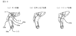
- Embodiment 3 of this invention It is a figure which shows Embodiment 3 of this invention, It is a side view which shows an example of the principal part of this invention, (a) is the state of the principal part in the ON state (closed state) of a circuit breaker, () Is a diagram showing the state of the main part at the trip completion position of the circuit breaker, and (c) is a diagram showing the state of the main part in the trip state of the circuit breaker.
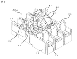
- FIG. 1 is an external perspective view of the circuit breaker according to the first embodiment of the present invention with the cover removed
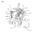
- FIG. 2 is a cross-sectional view showing the OFF state in FIG. 1
- FIGS. 3 is a partial side view
- FIG. 3 shows a closed state (ON)
- FIG. 4 shows an open state (OFF)
- FIG. 5 shows a trip state
- FIG. 6 shows a reset state.
- the circuit breaker 101 is configured using a casing 10 composed of a base 11 and a cover 12 made of an insulating material.
- a casing 10 composed of a base 11 and a cover 12 made of an insulating material.
- circuit breaker units 20 corresponding to the number of poles are arranged at intervals, and an open / close mechanism 40 having a well-known toggle link mechanism is disposed above the circuit breaker unit 20.
- the cover 12 covers the circuit breaker unit 20 of each pole on the base 11 and the opening / closing mechanism 40, and the operation handle 41 of the opening / closing mechanism 40 protrudes from the handle window hole 12 a of the cover 12.
- the circuit breaker units 20 for each pole are configured in the same manner, and the crossbar 32 is arranged on the base 11 so as to be orthogonal to the circuit breaker unit 20 for each pole in common with the circuit breaker unit 20 for each pole. Is done.
- the cross bar 32 is rotated around its axis by the opening / closing mechanism 40, and each movable contact 23 in the circuit breaker unit 20 of each pole is attached.
- the opening / closing mechanism 40 includes a known toggle link mechanism, and includes a known trip bar 33 that is driven by the tripping device 30.
- the circuit breaker unit 20 of each pole includes a power supply side terminal 24 provided on the base 11, a fixed contact 27 extending from the power supply side terminal 24 and having a fixed contact 21, and contacting and opening the fixed contact 21.
- the movable contact 22 to be separated, the movable contact 22 provided at one end and rotatably held by a cross bar 32, and the movable contact 23 connected to the movable contact 23 via a movable contact holder 26
- the fixed contact 21 and the movable contact 22 constitute an open / close contact that opens and closes the electric circuit. If the movable contact 22 contacts the fixed contact 21, the electrical circuit between the terminals 24 and 25 is turned on. If the movable contact 22 is separated from the fixed contact 21, the electrical circuit between the terminals 24 and 25. Is turned off. At this time, the arc generated between the movable contact 22 and the fixed contact 21 is extinguished by the arc extinguishing device 50.
- a cross bar 32 formed of a synthetic resin material is rotatably supported by a base 11 formed of a synthetic resin material or a fixed frame 43 attached to the base 11.
- a movable contact 23 having a movable contact 22 at one end is pivotally supported inside the cross bar 32 so as to rotate in conjunction with the rotation of the cross bar 32.
- a fixed contact 27 having a fixed contact 21 that contacts and separates from the movable contact 22 is mounted on the base 11.
- One end 46 a of the lower link 46 is connected to the cross bar 32 by a cross bar pin 36, and the other end 46 b of the lower link 46 is connected to one end 45 a of the upper link 45 by a link pin 47.
- the other end 45 b of the upper link 45 is connected to a lever 44 engaged with the latch 34.
- An opening / closing spring 48 is stretched between the link pin 47 and the handle arm 42 interlocking with the handle 41 formed of a synthetic resin material.
- the toggle link mechanism is constituted by the lower link 46, the upper link 45, and the link pin 47.
- the trip device 30 (see FIG. 2) operates, and the trip bar 33 on the paper surface of the trip bar 33 rotatably supported by the fixed frame 43 via the trip bar pin 37 is operated. The lower end is pressed and the trip bar 33 is rotated counterclockwise on the paper surface of FIG.
- the latch 34 is disengaged at the engaging portion 34b between the trip bar 33 and the latch 34 pivotally supported by the fulcrum 34a on the fixed frame 43. It rotates counterclockwise on the paper surface with the fulcrum 34a as a fulcrum.
- the handle 41 When the handle 41 is rotated leftward on the paper surface in the trip state (state of FIG. 5), the handle arm 42 rotates the lever 44 in conjunction with the circuit breaker.
- the lever 44 When the lever 44 is rotated and the engagement position at the engagement portion 34c (see FIG. 4) of the lever 44 and the latch 34 is exceeded, the latch 34 and the trip bar 33 are in the form of a torsion spring attached to the rotation shaft 34a of the latch 34.
- a rotational moment of the trip bar spring 35 (the center of this rotational moment is the fulcrum 34a of the latch 34, and the action points are 33a, 33b, 33c) is engaged by the engaging portion 34b (see FIG. 4). .
- the lever 44 is held by the latch 34 in a reset state (a state in which the lever 44 and the latch 34 are engaged as shown by 34c in FIG. 4), thereby completing the reset operation.
- the state where the reset operation is completed is illustrated in an enlarged manner in FIG.
- the action point at which the urging force of the trip bar spring 35 acts on the trip bar 33 is the tip of the trip bar spring 35, the tip of the trip bar spring 35, and the support point of the trip bar spring 35 (the rotation of the trip bar spring 35). It is formed between the center and the fulcrum 34a).
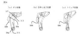
- FIG. 8 is a side view showing an example of the main part of the present invention, where (a) shows the state of the main part when the circuit breaker is on (closed state), and (b) is the trip of the circuit breaker. (C) is a figure which shows the state of the principal part in the trip state of a circuit breaker, respectively, in the state of the principal part in a completion position.
- the trip bar 33 In the closed state of the circuit breaker (see FIG. 8A), the trip bar 33 is in contact with one end of the trip bar spring 35 at the first engagement portion 33a. From this state, the circuit breaker is in contact with the first engaging portion 33a in the same way as described above until the trip completion position (see FIG. 8B) during the trip operation, so that the trip bar of the trip bar 33 during this time Since the rotational moment by the spring 35 is substantially constant, the load at the time of tripping of the trip bar 33 is not rapidly increased until the tripping by the tripping device is completed. Thereafter, after the completion of the tripping, the trip bar 33 and the trip bar spring 35 come into contact with a projection 33b provided separately from the first engagement portion 33a when the range reaches the trip position (see FIG.
- the wrinkles at the time of blocking adhere to the rotating shaft 37 portion of the trip bar 33, and this adhesion increases friction with respect to the rotation of the trip bar 33 at the rotating shaft 37 portion, thereby preventing the trip bar 33 from rotating. If the trip bar spring 35 has a small spring force, resetting may not be possible. However, according to the first embodiment, as described above, it becomes possible to prevent resetting from being impossible.
- the trip bar 33 has a small operating angle, and the trip bar 33 and the trip bar spring 35 are always at the tip of the trip bar spring 35 and one trip bar 33 as shown in the figure. Since it is difficult to obtain a large rotational moment due to contact with the engaging portion 33a, and resetting may be impossible, according to the first embodiment, as described above, it is possible to prevent resetting impossible. Is possible. Note that the center of the rotational moment acting on the trip bar 33 by the trip bar spring 35 (the fulcrum 34a of the latch 34) does not change, and the contact position (action point) between the trip bar 33 and the trip bar spring 35 changes (see FIG. 33a). By changing to 33b (in the case of the first embodiment) or 33c (in the case of the second and third embodiments described later), the rotational moment of the trip bar 33 increases.
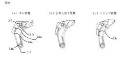
- Embodiment 2 FIG. The second embodiment of the present invention will be described below based on the example of FIG.
- one end of the trip bar spring 35 on the trip bar 33 side is bent from the bent portion 35a.
- the same effect as in the first embodiment can be obtained, and the trip bar 33 is in contact with the trip bar spring 35 and the first engagement portion 33a of the trip bar 33 until the trip by the trip device is completed.
- the return force of the trip bar 33 at the time of resetting can be increased without increasing the load at the time of removal and by changing the contact position to the second engaging portion 33c of the trip bar 33 after completion of the tripping, It becomes possible to prevent inability to reset mainly due to the influence of the melt, soot, etc. generated at the time of short circuit interruption.
- FIG. 3 A third embodiment of the present invention will be described below based on the example of FIG.
- the protrusion 33b of the trip bar 33 shown in the first embodiment and the trip bar spring 35 having one end on the trip bar 33 side shown in the second embodiment bent from the bent portion 35a are used in combination. This makes it possible to obtain a greater effect.
- Feature 1 A handle arm pivotally supported on a fixed frame and operated by a handle, a toggle link having an upper link and a lower link, and an open / close spring stretched between the connecting portion and the handle arm A mechanism, a crossbar connected to the lower link by a crossbar pin and rotated by the operation of the toggle link mechanism; a movable contact at one end;
- a circuit breaker switching mechanism having a movable contact that is interlocked with the rotation of the movable contact and a fixed contact that has a fixed contact that contacts and separates from the movable contact, a fixed frame is used for the trip operation by the trip device.
- the trip bar protrudes toward the rotation center side of the trip bar spring, and has a projection that engages with the trip bar spring at the trip position from the trip completion position.
- Feature 2 A handle arm pivotally supported by a fixed frame and operated by a handle, a toggle link having an upper link and a lower link, and an open / close spring stretched between the connecting portion and the handle arm A mechanism, a crossbar connected to the lower link by a crossbar pin and rotated by the operation of the toggle link mechanism; a movable contact at one end;
- a circuit breaker switching mechanism having a movable contact that is interlocked with the rotation of the movable contact and a fixed contact that has a fixed contact that contacts and separates from the movable contact, a fixed frame is used for the trip operation by the trip device.
Landscapes
- Breakers (AREA)
Abstract
Description
以下、本発明の実施の形態1を示すにあたり回路遮断器の開閉機構を図に基づいて説明する。図1はこの発明の実施の形態1による回路遮断器のカバーを外した外観斜視図、図2は図1におけるOFF状態を表す断面図、図3~4は回路遮断器の開閉機構を示す要部側面図であり、図3は閉路(オン)状態、図4は開路(オフ)状態、図5はトリップ状態、図6はリセット状態を示す。
リセット動作が完了した状態は、図7に拡大して例示してある。トリップバー33にトリップバースプリング35の付勢力が作用する作用点が、トリップバースプリング35の先端部と、トリップバースプリング35の先端部と前記トリップバースプリング35の支承点(トリップバースプリング35の回転中心である支点34a)との間に形成されている。
この状態から遮断器はトリップ動作を行う過程で引外し完了位置(図8(b)参照)までは前記同様に第一係合部33aで当接していることでこの間のトリップバー33のトリップバースプリング35による回転モーメントはほぼ一定であるため、引外し装置による引外し完了まではトリップバー33の引外し時の荷重を急激に増大させることはない。その後、引外し完了後、トリップ位置(図8(c)参照)までの範囲になるとトリップバー33とトリップバースプリング35は第一係合部33aと別に設けられた突起33bで当接する。そのため、トリップバー33とトリップバースプリング35はトリップバースプリング35の根本側で当接することになりトリップバースプリング35による回転モーメントが急激に増大する。すなわち、トリップバー33が前記トリップ動作(紙面上の時計方向の回転)と逆の動き(紙面上の反時計方向の回転)を行うリセット動作においては、リセット時にトリップバー33の復帰力が増大することになり、主に短絡遮断時に発生する溶融物、煤等の影響に起因するリセット不能を防止することが可能になる。つまり、遮断時の煤がトリップバー33の回転軸37部に付着しこの付着により回転軸37部でのトリップバー33の回転に対する摩擦が増大して、トリップバー33の回転を妨げてしまうことにより、トリップバースプリング35のスプリング力が小さいとリセット不能になる場合が生じるが、本実施の形態1によれば、前述のように、リセット不能を防止することが可能になる。
なお、トリップバー33にトリップバースプリング35によって作用する回転モーメントの中心(ラッチ34の支点34a)は変わらず、トリップバー33とトリップバースプリング35の当接位置(作用点)が変わる(図示33aが33b(実施の形態1の場合)もしくは33c(後述の実施の形態2,3の場合)に変わる)ことにより、トリップバー33の回転モーメントが増大する。
以下、本発明の実施の形態2を図9の実施例に基づいて説明する。2段階で回転モーメントを得るために、トリップバースプリング35のトリップバー33側の一端を屈曲部35aから曲げた形状とする。これにより、実施の形態1と同様な効果が得られ、引外し装置による引外し完了まではトリップバー33はトリップバースプリング35とトリップバー33の第一係合部33aで当接しているので引外し時の荷重を増大させることなく、また引外し完了後は当接位置がトリップバー33の第二係合部33cに変わることでリセット時のトリップバー33の復帰力を増大させることができ、主に短絡遮断時に発生する溶融物、煤等の影響に起因するリセット不能を防止することが可能になる。
以下、本発明の実施の形態3を図10の実施例に基づいて説明する。
実施の形態1で示したトリップバー33の突起33bと、実施の形態2で示したトリップバー33側の一端を屈曲部35aから曲げた形状としたトリップバースプリング35とを併用したものである。これにより、更に大きな効果を得ることが可能となる。
特徴点1:固定フレームに回動可能に枢支され、ハンドルにより操作されるハンドルアームと、上リンクと下リンクを有しその連結部分と上記ハンドルアーム間に開閉スプリングが張架されたトグルリンク機構と、上記下リンクにクロスバーピンにより連結されて上記トグルリンク機構の動作により回動するクロスバーと、一端に可動接点を有し、他端が回動可能に枢支され、上記クロスバーの回動に連動する可動接触子と、上記可動接点と接離する固定接点を有した固定接触子とを備えた回路遮断器の開閉機構部において、引外し装置による引外し動作においては固定フレームに回動可能に枢支されるトリップバーとラッチとレバーを有しその3部品の係合およびラッチ回転軸に設けたトリップバースプリングの付勢力によりリセット動作を行う引外し機構部を有する回路遮断器において、上記トリップバーは、上記トリップバースプリングの回転中心側に突出し、引外し完了位置からトリップ位置において上記トリップバースプリングと係合する突起を有するものである。
特徴点2:固定フレームに回動可能に枢支され、ハンドルにより操作されるハンドルアームと、上リンクと下リンクを有しその連結部分と上記ハンドルアーム間に開閉スプリングが張架されたトグルリンク機構と、上記下リンクにクロスバーピンにより連結されて上記トグルリンク機構の動作により回動するクロスバーと、一端に可動接点を有し、他端が回動可能に枢支され、上記クロスバーの回動に連動する可動接触子と、上記可動接点と接離する固定接点を有した固定接触子とを備えた回路遮断器の開閉機構部において、引外し装置による引外し動作においては固定フレームに回動可能に枢支されるトリップバーとラッチとレバーを有しその3部品の係合およびラッチ回転軸に設けたトリップバースプリングの付勢力によりリセット動作を行う引外し機構部を有する回路遮断器において、上記引外し機構部のトリップバースプリングの一端を曲げることで、2段階で回転モーメントを得るものである。
なお、本発明は、その発明の範囲内において、各実施の形態を適宜、変形、省略、組み合わせることができる。
22 可動接点、 23 可動接触子、 27 固定接触子、
32 クロスバー、 33 トリップバー、
33a 第一係合部(作用点)、 33b 突起(作用点)、
33c 第二係合部(作用点)、 34 ラッチ、
34a ラッチ34の支点(回転軸)(回転モーメントの中心)(トリップバースプリングの支承点)、
34b 係合部(トリップバー33とラッチ34との係合部)、
34c 係合部(レバー44とラッチ34との係合部)、
35 トリップバースプリング、 36 クロスバーピン、
37 トリップバーピン(トリップバー33の支点)、
41 ハンドル、 42 ハンドルアーム、 43 固定フレーム、
44 レバー、 44a レバー44の支点、
45 上リンク、 45a 上リンク45の一端、
45b 上リンク45の他端、 46 下リンク、
46a 下リンク46の一端、 46b 下リンク46の他端、
47 リンクピン、 48 開閉スプリング、 101 回路遮断器
Claims (3)
- 過電流引外し装置によりトリップバーが駆動されて遮断動作しトリップバースプリングの付勢力により前記トリップバーがリセット動作を行う回路遮断器において、
前記トリップバーにトリップバースプリングの付勢力が作用する作用点が、前記トリップバースプリングの先端部と、前記トリップバースプリングの先端部と前記トリップバースプリングの支承点との間に形成されていることを特徴とする回路遮断器。 - 請求項1に記載の回路遮断器において、前記トリップバースプリングの先端部と前記トリップバースプリングの支承点との間に設けられた作用点が、前記トリップバーに設けられた突起により形成されていることを特徴とする回路遮断器。
- 請求項1または請求項2に記載の回路遮断器において、前記トリップバースプリングの先端部と前記トリップバースプリングの支承点との間に設けられた作用点が、前記トリップバースプリングに設けられた屈曲部により形成されていることを特徴とする回路遮断器。
Priority Applications (5)
| Application Number | Priority Date | Filing Date | Title |
|---|---|---|---|
| CN201580073431.3A CN107112169B (zh) | 2015-01-09 | 2015-01-09 | 电路断路器 |
| JP2016568242A JP6289677B2 (ja) | 2015-01-09 | 2015-01-09 | 回路遮断器 |
| PCT/JP2015/050470 WO2016111000A1 (ja) | 2015-01-09 | 2015-01-09 | 回路遮断器 |
| KR1020177015508A KR101948454B1 (ko) | 2015-01-09 | 2015-01-09 | 회로 차단기 |
| EP15876875.4A EP3244435B1 (en) | 2015-01-09 | 2015-01-09 | Circuit breaker |
Applications Claiming Priority (1)
| Application Number | Priority Date | Filing Date | Title |
|---|---|---|---|
| PCT/JP2015/050470 WO2016111000A1 (ja) | 2015-01-09 | 2015-01-09 | 回路遮断器 |
Publications (1)
| Publication Number | Publication Date |
|---|---|
| WO2016111000A1 true WO2016111000A1 (ja) | 2016-07-14 |
Family
ID=56355720
Family Applications (1)
| Application Number | Title | Priority Date | Filing Date |
|---|---|---|---|
| PCT/JP2015/050470 WO2016111000A1 (ja) | 2015-01-09 | 2015-01-09 | 回路遮断器 |
Country Status (5)
| Country | Link |
|---|---|
| EP (1) | EP3244435B1 (ja) |
| JP (1) | JP6289677B2 (ja) |
| KR (1) | KR101948454B1 (ja) |
| CN (1) | CN107112169B (ja) |
| WO (1) | WO2016111000A1 (ja) |
Citations (3)
| Publication number | Priority date | Publication date | Assignee | Title |
|---|---|---|---|---|
| JPS481988U (ja) * | 1971-05-25 | 1973-01-11 | ||
| JPH0836963A (ja) * | 1994-02-03 | 1996-02-06 | Kloeckner Moeller Gmbh | ロック機構を有する遮断器 |
| JP2008097833A (ja) * | 2006-10-05 | 2008-04-24 | Kawamura Electric Inc | 回路遮断器 |
Family Cites Families (6)
| Publication number | Priority date | Publication date | Assignee | Title |
|---|---|---|---|---|
| KR880014610A (ko) * | 1987-05-18 | 1988-12-24 | 시키 모리야 | 회로 차단기 |
| JPH0747780Y2 (ja) * | 1987-05-18 | 1995-11-01 | 三菱電機株式会社 | 回路しゃ断器 |
| ZA898764B (en) * | 1988-12-08 | 1990-08-29 | Westinghouse Electric Corp | Electrical circuit breaker handle locking apparatus |
| CN2407450Y (zh) * | 2000-01-29 | 2000-11-22 | 浙江德力西电器股份有限公司 | 小型断路器的操作机构 |
| US6727788B1 (en) * | 2002-06-20 | 2004-04-27 | Siemens Energy & Automation, Inc. | Latch mechanism for a circuit breaker |
| CN2679835Y (zh) * | 2004-02-20 | 2005-02-16 | 上海电器科学研究所(集团)有限公司 | 断路器传动机构 |
-
2015
- 2015-01-09 JP JP2016568242A patent/JP6289677B2/ja active Active
- 2015-01-09 WO PCT/JP2015/050470 patent/WO2016111000A1/ja active Application Filing
- 2015-01-09 EP EP15876875.4A patent/EP3244435B1/en active Active
- 2015-01-09 KR KR1020177015508A patent/KR101948454B1/ko active IP Right Grant
- 2015-01-09 CN CN201580073431.3A patent/CN107112169B/zh active Active
Patent Citations (3)
| Publication number | Priority date | Publication date | Assignee | Title |
|---|---|---|---|---|
| JPS481988U (ja) * | 1971-05-25 | 1973-01-11 | ||
| JPH0836963A (ja) * | 1994-02-03 | 1996-02-06 | Kloeckner Moeller Gmbh | ロック機構を有する遮断器 |
| JP2008097833A (ja) * | 2006-10-05 | 2008-04-24 | Kawamura Electric Inc | 回路遮断器 |
Non-Patent Citations (1)
| Title |
|---|
| See also references of EP3244435A4 * |
Also Published As
| Publication number | Publication date |
|---|---|
| CN107112169A (zh) | 2017-08-29 |
| EP3244435B1 (en) | 2019-08-28 |
| KR101948454B1 (ko) | 2019-02-14 |
| JP6289677B2 (ja) | 2018-03-07 |
| KR20170082587A (ko) | 2017-07-14 |
| EP3244435A1 (en) | 2017-11-15 |
| JPWO2016111000A1 (ja) | 2017-04-27 |
| CN107112169B (zh) | 2019-03-29 |
| EP3244435A4 (en) | 2018-08-15 |
Similar Documents
| Publication | Publication Date | Title |
|---|---|---|
| EP2015340B1 (en) | Time delay output apparatus for circuit breaker | |
| WO2016074321A1 (zh) | 断路器操作机构 | |
| JP4059058B2 (ja) | 回路しゃ断器 | |
| JP4918890B2 (ja) | 回路遮断器 | |
| KR20130110182A (ko) | 회로 차단기 | |
| KR101144585B1 (ko) | 소형 회로차단기의 트립 경보 장치 | |
| JP5048569B2 (ja) | 回路遮断器 | |
| JP4960072B2 (ja) | 回路遮断器 | |
| KR20100037554A (ko) | 접촉 아암 조립체 및 접촉 아암 조립체 조립 방법 | |
| JP6289677B2 (ja) | 回路遮断器 | |
| JP5418024B2 (ja) | 回路遮断器 | |
| JP5333253B2 (ja) | 回路遮断器 | |
| EP3367416B1 (en) | Molded-case circuit breaker with main contact interlock feature | |
| JP4029664B2 (ja) | 回路しゃ断器 | |
| KR100885849B1 (ko) | 컨택트 온 기구를 가지는 배선용 차단기 | |
| US2320357A (en) | Circuit breaker | |
| KR100643049B1 (ko) | 배선용 차단기 | |
| KR101721106B1 (ko) | 회로 차단기 | |
| JP6395676B2 (ja) | 回路遮断器 | |
| JP2010182607A (ja) | 回路遮断器 | |
| JP5554210B2 (ja) | 回路遮断器 | |
| JP2005038769A (ja) | 多極回路遮断器 | |
| JP4262349B2 (ja) | 多極回路遮断器 | |
| KR101751948B1 (ko) | 회로차단기의 트립버튼 | |
| JP2015141892A (ja) | 配線用遮断器のトリップ機構 |
Legal Events
| Date | Code | Title | Description |
|---|---|---|---|
| 121 | Ep: the epo has been informed by wipo that ep was designated in this application |
Ref document number: 15876875 Country of ref document: EP Kind code of ref document: A1 |
|
| ENP | Entry into the national phase |
Ref document number: 2016568242 Country of ref document: JP Kind code of ref document: A |
|
| REEP | Request for entry into the european phase |
Ref document number: 2015876875 Country of ref document: EP |
|
| WWE | Wipo information: entry into national phase |
Ref document number: 2015876875 Country of ref document: EP |
|
| ENP | Entry into the national phase |
Ref document number: 20177015508 Country of ref document: KR Kind code of ref document: A |
|
| NENP | Non-entry into the national phase |
Ref country code: DE |