WO2016110915A1 - 車載機、車載機診断システム - Google Patents
車載機、車載機診断システム Download PDFInfo
- Publication number
- WO2016110915A1 WO2016110915A1 PCT/JP2015/006364 JP2015006364W WO2016110915A1 WO 2016110915 A1 WO2016110915 A1 WO 2016110915A1 JP 2015006364 W JP2015006364 W JP 2015006364W WO 2016110915 A1 WO2016110915 A1 WO 2016110915A1
- Authority
- WO
- WIPO (PCT)
- Prior art keywords
- vehicle
- index data
- target
- sensor
- unit
- Prior art date
- Legal status (The legal status is an assumption and is not a legal conclusion. Google has not performed a legal analysis and makes no representation as to the accuracy of the status listed.)
- Ceased
Links
Images




Classifications
-
- G—PHYSICS
- G07—CHECKING-DEVICES
- G07C—TIME OR ATTENDANCE REGISTERS; REGISTERING OR INDICATING THE WORKING OF MACHINES; GENERATING RANDOM NUMBERS; VOTING OR LOTTERY APPARATUS; ARRANGEMENTS, SYSTEMS OR APPARATUS FOR CHECKING NOT PROVIDED FOR ELSEWHERE
- G07C5/00—Registering or indicating the working of vehicles
- G07C5/008—Registering or indicating the working of vehicles communicating information to a remotely located station
-
- G—PHYSICS
- G07—CHECKING-DEVICES
- G07C—TIME OR ATTENDANCE REGISTERS; REGISTERING OR INDICATING THE WORKING OF MACHINES; GENERATING RANDOM NUMBERS; VOTING OR LOTTERY APPARATUS; ARRANGEMENTS, SYSTEMS OR APPARATUS FOR CHECKING NOT PROVIDED FOR ELSEWHERE
- G07C5/00—Registering or indicating the working of vehicles
- G07C5/08—Registering or indicating performance data other than driving, working, idle, or waiting time, with or without registering driving, working, idle or waiting time
- G07C5/0816—Indicating performance data, e.g. occurrence of a malfunction
-
- G—PHYSICS
- G07—CHECKING-DEVICES
- G07C—TIME OR ATTENDANCE REGISTERS; REGISTERING OR INDICATING THE WORKING OF MACHINES; GENERATING RANDOM NUMBERS; VOTING OR LOTTERY APPARATUS; ARRANGEMENTS, SYSTEMS OR APPARATUS FOR CHECKING NOT PROVIDED FOR ELSEWHERE
- G07C5/00—Registering or indicating the working of vehicles
- G07C5/08—Registering or indicating performance data other than driving, working, idle, or waiting time, with or without registering driving, working, idle or waiting time
- G07C5/0816—Indicating performance data, e.g. occurrence of a malfunction
- G07C5/0825—Indicating performance data, e.g. occurrence of a malfunction using optical means
-
- H—ELECTRICITY
- H04—ELECTRIC COMMUNICATION TECHNIQUE
- H04L—TRANSMISSION OF DIGITAL INFORMATION, e.g. TELEGRAPHIC COMMUNICATION
- H04L67/00—Network arrangements or protocols for supporting network services or applications
- H04L67/01—Protocols
- H04L67/12—Protocols specially adapted for proprietary or special-purpose networking environments, e.g. medical networks, sensor networks, networks in vehicles or remote metering networks
Definitions
- the present disclosure relates to an in-vehicle unit that diagnoses whether or not other in-vehicle devices existing in or around the device are operating normally, and an in-vehicle device diagnosis system.
- an in-vehicle device mounted on each of a plurality of vehicles performs wireless communication with other in-vehicle devices existing within a predetermined range from the own device without using a wide area communication network.
- host vehicles performs wireless communication with other in-vehicle devices existing within a predetermined range from the own device without using a wide area communication network.
- a system has been proposed.
- communication performed by this type of vehicle-mounted device is called vehicle-to-vehicle communication.
- This type of in-vehicle device detects a predetermined physical state quantity such as a positioning radio wave receiver (for example, a GPS receiver) that identifies its current position by receiving radio waves from a positioning satellite, and acceleration and rotational angular velocity.
- Sensors that is, acceleration sensors, gyro sensors, etc.
- the detection result of the acceleration sensor or the gyro sensor is used to correct the current position specified by the positioning radio wave receiver.
- the vehicle-mounted device may include a sensor that detects physical state quantities such as illuminance and temperature in addition to acceleration and rotational angular velocity.
- the in-vehicle device transmits information related to the own device such as the current position and acceleration of the own device to a service providing terminal (for example, a roadside device) that provides a predetermined service to the in-vehicle device, thereby providing the service providing terminal.
- a service providing terminal for example, a roadside device
- the in-vehicle device can enjoy the service according to the current position by providing the current position information to the service providing terminal.
- Patent Document 1 discloses a technique in which a threshold value is set in advance with respect to the operation range of the acceleration sensor, and whether or not the acceleration sensor is operating normally using the threshold value is disclosed. ing.
- the vehicle-mounted device such as an acceleration sensor or a gyro sensor
- information provided to the service providing terminal such as the current position is not accurate information.
- the current position may be estimated at a position different from the actual position.
- the in-vehicle device may not be able to properly receive the service provided by the service providing terminal.
- Patent Document 1 when the tendency (operation range, etc.) of the operation of the sensor included in the vehicle-mounted device is known in advance, a threshold value suitable for the tendency of the operation can be set. By using the threshold value, it can be determined whether or not the sensor is operating normally.
- the external environment in which the in-vehicle device is used can change dynamically, it is difficult to specify the operational tendency of various sensors (for example, acceleration sensors) used in the in-vehicle device.
- the external environment here refers to an element that affects the detection value of the sensor. Mainly, the road surface shape on which the host vehicle is traveling, the road shape (curvature), the road gradient, Whether you are driving on a bridge, time zone, weather, etc.
- a vehicle equipped with a certain in-vehicle device is referred to as a host vehicle, and the above-described specific example is given by taking an acceleration sensor as an example of a sensor provided in the in-vehicle device.
- the vibration generated in the vehicle body is relatively small and the vertical force is less likely to act on the in-vehicle device. For this reason, it is difficult for the acceleration sensor to detect vertical acceleration. Therefore, even if the host vehicle is traveling on a flat road, the acceleration sensor may not be operating normally if the acceleration sensor detects an acceleration of a certain value or more in the vertical direction. Concerned.
- the up-down direction here refers to the direction where gravity acts.
- the acceleration sensor when the host vehicle is traveling on a road with many irregularities or on a bridge, a relatively large vertical force acts on the in-vehicle device. For this reason, the acceleration sensor also outputs vertical acceleration. The magnitude of the acceleration detected at this time varies depending on the external environment such as a running road.
- the situation in which the acceleration sensor detects acceleration in the vertical direction means that the host vehicle is operating normally when the host vehicle is traveling on a road with many irregularities, while the host vehicle is When traveling on a flat road, it means that a problem has occurred.
- the actual external environment is different from the situation assumed in determining the threshold. In such a case, it may be erroneously determined that the acceleration sensor is not operating normally.
- the relationship between the operation of the acceleration sensor and the external environment has been described, but the same applies to sensors for detecting other physical state quantities.
- the in-vehicle device can acquire information about the external environment that affects the operation status of the sensor, it is determined whether the sensor is operating normally by applying a threshold value according to the external environment. Can do.
- An object of the present disclosure is to provide an in-vehicle device and an in-vehicle device diagnosis system capable of diagnosing whether or not a sensor device included in the in-vehicle device is operating normally without using information about the external environment. It is to provide.
- the in-vehicle device used in each of a plurality of host vehicles including a target vehicle and a plurality of surrounding vehicles around the target vehicle is as follows.
- the in-vehicle device used for each host vehicle is based on a wireless communication device that transmits and receives information by inter-vehicle communication, a sensor device that detects a predetermined physical state quantity acting on the on-vehicle device itself, and a detection result of the sensor device.
- An index data generation unit that generates index data indicating the operation status of the sensor device, and transmits the generated index data from each host vehicle via a wireless communication device.
- An in-vehicle device (referred to as an in-vehicle device) used for the target vehicle includes a communication processing unit, a determination criterion determination unit, and a separate device diagnosis unit.
- the communication processing unit acquires the separate device index data, which is index data transmitted from a plurality of surrounding vehicles (or on-vehicle devices of peripheral vehicles also referred to as peripheral on-vehicle devices) via a wireless communication device.
- the determination criterion determination unit is a separate sensor device that is a sensor device included in a target peripheral vehicle-mounted device as a predetermined diagnosis target among a plurality of peripheral vehicle-mounted devices based on the separate device index data acquired by the communication processing unit.
- the separate device diagnosis unit operates normally by operating the separate sensor device included in the target peripheral in-vehicle device by comparing the separate device determination criterion determined by the determination criterion determining unit with the separate device index data acquired from the target peripheral in-vehicle device. It is determined whether or not.
- the determination criterion determining unit uses the index data received from the peripheral vehicle-mounted device, and the sensor device included in the vehicle or the vehicle-mounted device that is a diagnostic target among the peripheral vehicle-mounted devices operates normally.
- the determination criteria for determining whether or not are sequentially determined.
- the separate machine diagnosis unit determines whether or not the sensor device included in the in-vehicle device as the diagnosis target is operating normally, using the determination criterion determined by the determination criterion determination unit.
- the in-vehicle devices that are diagnostic targets and the peripheral in-vehicle devices that provide the index data that is the basis for generating the determination criteria are all in a range in which inter-vehicle communication with the target in-vehicle device can be performed, that is, relatively small. Exists in range.
- both the in-vehicle device that provides the index data that is the basis for generating the judgment criteria and the in-vehicle device that is the diagnosis target are similarly affected by the external environment.
- the index data of the sensor machine provided and the index data that is the basis for determining the determination criteria are data that are similarly affected by the external environment.
- the determination criterion dynamically determined by the determination criterion determination unit is a criterion reflecting the influence of the external environment.
- the behavior of each vehicle existing in a relatively close area is expected to be similar, it is expected that the operation statuses of the sensor devices included in each of the plurality of peripheral vehicle-mounted devices are also similar.
- the sensor device is normal. Suggests the possibility of not working.
- the in-vehicle device used in each of a plurality of host vehicles including the target vehicle and at least one surrounding vehicle in the vicinity thereof.
- the in-vehicle device used for each host vehicle is based on a wireless communication device that transmits and receives information by inter-vehicle communication, a sensor device that detects a predetermined physical state quantity acting on the on-vehicle device itself, and a detection result of the sensor device.
- An index data generation unit that generates index data including an index value indicating the operation status of the sensor device, and transmits the index data generated by the index data generation unit from each host vehicle via a wireless communication device.
- An in-vehicle device (referred to as an in-vehicle device) used in the target vehicle includes a communication processing unit, a determination criterion determination unit, and an own device diagnosis unit.
- the communication processing unit acquires the separate device index data that is the index data transmitted from at least one peripheral vehicle (or at least one peripheral vehicle-mounted device) via the wireless communication device.
- the determination criterion determination unit determines its own device determination criterion, which is a determination criterion for determining whether or not the sensor device included in the target in-vehicle device is operating normally. Determine sequentially.
- the self-machine diagnosis unit compares the self-machine determination criterion determined by the determination standard determination unit with the self-machine index data indicating that it is index data of the target in-vehicle device, so that the sensor device of the target in-vehicle device is Determine whether it is operating.
- the determination criterion determination unit sequentially determines a determination criterion for determining whether the sensor device included in the target in-vehicle device is operating normally using the index data received from the peripheral in-vehicle device. Then, the own device diagnosis unit diagnoses whether or not the sensor device included in the target in-vehicle device is operating normally using the determination criterion determined by the determination criterion determination unit.
- an in-vehicle device diagnosis system including a plurality of in-vehicle devices mounted on each of a plurality of host vehicles including the target vehicle and at least one surrounding vehicle around the target vehicle.
- Each in-vehicle device includes a wireless communication device that performs transmission and reception of information by inter-vehicle communication and a sensor device that detects a predetermined physical state quantity acting on the in-vehicle device itself.
- the vehicle-mounted device includes an index data generation unit, a communication processing unit, a determination criterion determination unit, and a separate machine diagnosis unit.
- the index data generation unit generates index data including an index value indicating the operation status of the sensor machine based on the detection result of the sensor machine.
- the communication processing unit causes the index data generated by the index data generation unit to be transmitted to the wireless communication device, and is a separate device that is index data transmitted from at least one peripheral vehicle-mounted device mounted on at least one peripheral vehicle. Index data is acquired via a wireless communication device.
- the determination criterion determination unit is normal for the separate sensor device that is the sensor device included in the target peripheral on-vehicle device as a predetermined diagnosis target among the plurality of peripheral on-vehicle devices.
- the separate apparatus determination criterion which is a determination criterion for determining whether or not the device is operating, is sequentially determined.
- the separate device diagnosis unit compares the separate device determination criterion determined by the determination criterion determination unit with the separate device index data acquired by the communication processing unit from the target peripheral on-vehicle device, thereby providing another sensor device included in the target peripheral on-vehicle device. It is determined whether or not is operating normally.
- This example of the in-vehicle device diagnosis system is a system realized by providing a plurality of in-vehicle devices having the above-described configuration as the first example of the in-vehicle device. That is, due to the same action as the first example for the above-described in-vehicle device, each in-vehicle device included in the system operates normally without using the information about the external environment. It is possible to diagnose whether or not
- FIG. 10 is a block diagram illustrating an example of a schematic configuration of a controller in Modification 2.
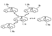
- FIG. 1 is a diagram illustrating an example of a schematic configuration of an in-vehicle device diagnosis system 100 according to the present disclosure.
- This in-vehicle device diagnosis system 100 includes an in-vehicle device 1 that is used one by one in each of a plurality of vehicles, and a center 3 provided outside each vehicle.
- the center 3 is connected to a wide area communication network 2 such as a telephone line network or the Internet.
- Vehicles indicated by reference signs A and B in FIG. 1 represent vehicles equipped with the vehicle-mounted device 1.
- the vehicle-mounted device 1 mounted on each vehicle uses a radio wave in a pre-assigned frequency band and communicates with another vehicle-mounted device 1 existing in the vicinity of the terminal itself through wireless communication (so-called vehicle-to-vehicle communication) not via the wide area communication network 2. )I do.
- the frequency band used for vehicle-to-vehicle communication is, for example, a 700 MHz band radio wave, a 5.8 to 5.9 GHz band, 2.4 GHz, or the like.
- the area around the terminal here refers to the range where inter-vehicle communication can be performed.
- the range in which vehicle-to-vehicle communication and road-to-vehicle communication can be performed may be designed as appropriate, and is often designed to be several tens to several hundreds of meters.
- another in-vehicle device 1 existing around the terminal is also referred to as a peripheral in-vehicle device 1.
- the in-vehicle device diagnosis system 100 and the in-vehicle device 1 will be described with the vehicle A also referred to as a subject vehicle or a first vehicle, and the vehicle B also referred to as a surrounding vehicle, another vehicle, or a second vehicle.
- the peripheral vehicle B refers to a vehicle equipped with the vehicle-mounted device 1 (also referred to as another vehicle-mounted device) that performs vehicle-to-vehicle communication with the vehicle-mounted device 1 mounted in the target vehicle A.
- the relationship between the target vehicle and the surrounding vehicle is relatively determined. If the vehicle B is the target vehicle, the vehicle A is naturally a surrounding vehicle for the vehicle B.
- the vehicle on which the vehicle-mounted device 1 is mounted is also referred to as a host vehicle, and both the vehicle A and the vehicle B correspond to this.
- the vehicle mounted on the target vehicle A is the vehicle-mounted device 1A, and the first vehicle-mounted device 1 Also referred to as 1A, target vehicle-mounted device 1A.
- an in-vehicle device 1B that is, a peripheral in-vehicle device
- a second in-vehicle device 1B and is also referred to as a second in-vehicle device 1B and another in-vehicle device 1B.
- Each in-vehicle device 1 performs radio communication (so-called road-to-vehicle communication) without using the wide-area communication network 2 with a roadside device provided on or along the road using radio waves in a pre-assigned frequency band. May be.
- Each in-vehicle device 1 may perform vehicle-to-vehicle communication or road-to-vehicle communication in accordance with a known communication standard for performing vehicle-to-vehicle communication or road-to-vehicle communication.
- the in-vehicle device 1 is an IEEE 1609.0 (Guide for Wireless Access in Vehicular).
- the vehicle-to-vehicle communication and the road-to-vehicle communication may be performed in accordance with the standard of Environment.
- the vehicle-mounted device 1 and the roadside device are not distinguished, they are simply referred to as communication terminals.
- An identification code (referred to as a terminal ID) for identifying each of a plurality of communication terminals is set in each of the communication terminals (the in-vehicle device 1 and the roadside device) provided in the in-vehicle device diagnosis system 100.
- the data transmitted by each communication terminal includes the terminal ID of the transmission terminal, and the communication terminal that has received the data can identify the transmission terminal by the terminal ID included in the data. It has become.
- Each of the plurality of in-vehicle devices 1 included in the in-vehicle device diagnosis system 100 is a sensor (that is, an acceleration sensor, a gyro sensor, or the like) that is also referred to as a sensor device that detects a predetermined physical state quantity such as acceleration or rotational angular velocity acting on the terminal. ).
- the sensor of the target vehicle A is also referred to as a sensor device, whereas the sensor of the surrounding vehicle B is also referred to as another sensor or another sensor device.
- Each vehicle-mounted device 1 transmits data (an index data described later) indicating the operation status of various sensors included in the own terminal by inter-vehicle communication, and another vehicle-mounted device 1 existing around the own terminal transmits. Received index data. That is, the in-vehicle device 1A transmits the index data of its own terminal (also referred to as own device index data) and receives the index data (also referred to as separate device index data) transmitted by the peripheral in-vehicle device 1B.
- own device index data also referred to as own device index data
- the index data also referred to as separate device index data
- the traveling environment of the target vehicle A and the surrounding vehicle B is substantially equal, and the surrounding vehicle B is highly likely to behave like the target vehicle A (acceleration, deceleration, turning, etc.). Therefore, it can be expected that the operation status (detected value, etc.) of the sensor provided in the in-vehicle device 1A and the operation status of the sensor provided in the peripheral in-vehicle device 1B are also highly similar.
- the environment in which the vehicle is traveling includes the road surface shape of the traveling road, the curvature of the road, the gradient of the road, the time zone, the weather, and the like.
- the in-vehicle device 1 of the in-vehicle device diagnosis system 100 includes the own terminal by comparing the operation state of the sensor included in the own terminal with the operation state of the sensor included in another in-vehicle device 1.
- the sensor is diagnosed, or the sensor included in the peripheral vehicle-mounted device 1B is diagnosed.
- the diagnosis here refers to determining whether or not various sensors are operating normally.
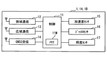
- the in-vehicle device 1 includes a controller 11, a narrow area communication device 12, a wide area communication device 13, a GNSS receiver 14, an acceleration sensor 15, a gyro sensor 16, and an illuminance sensor 17.
- the controller 11, the narrow area communication device 12, the wide area communication device 13, the GNSS receiver 14, the acceleration sensor 15, the gyro sensor 16, and the illuminance sensor 17 are connected so as to be able to communicate with each other.
- the narrow-area communication device 12 includes an antenna capable of transmitting and receiving radio waves in a frequency band used for vehicle-to-vehicle communication and road-to-vehicle communication, and another communication terminal (on-vehicle device) existing around the own terminal via the antenna. 1 and roadside machine). More specifically, the narrow area communication device 12 demodulates the signal received by the antenna and outputs the demodulated signal to the controller 11, modulates the data input from the controller 11, further converts it into a radio wave, and transmits it. This narrow area communication device 12 is also referred to as a wireless communication device.
- the wide area communication device 13 is connected to the wide area communication network 2 and performs communication with the center 3.
- the wide area communication device 13 demodulates the signal received via the wide area communication network 2 and provides it to the controller 11, modulates the baseband signal input from the controller 11, and transmits it to the center 3.
- the GNSS receiver 14 acquires information indicating the current position of the GNSS receiver 14 by receiving a radio wave from a satellite (referred to as a GNSS satellite) used in a GNSS (Global Navigation Satellite System).
- the current position acquired by the GNSS receiver 14 may be expressed by, for example, latitude, longitude, and altitude.
- the altitude may represent a height from a predetermined reference surface (for example, the sea surface). Note that information is used not only as not countable but also countable.
- the position information acquired by the GNSS receiver 14 is provided to the controller 11 sequentially (for example, every 100 milliseconds).
- the GNSS receiver 14 is an optional element and may not be provided.
- the GNSS receiver 14 is also referred to as a position information output device.
- the acceleration sensor 15 is a three-axis acceleration sensor that detects acceleration acting in three orthogonal directions.
- the three axial directions for detecting acceleration are referred to as the X-axis, Y-axis, and Z-axis directions, respectively.
- the X-axis direction coincides with the vehicle front-rear direction
- the Y-axis direction matches the vehicle width direction
- the Z-axis direction matches the height direction.
- Data representing the acceleration for each axial direction detected by the acceleration sensor 15 is sequentially output to the controller 11.
- the interval (output interval) at which the acceleration sensor 15 outputs the detection value may be designed as appropriate, for example, 100 milliseconds. Of course, other values may be used for the output interval, for example, 50 milliseconds or 200 milliseconds.
- the acceleration sensor 15 is a three-axis acceleration sensor here, an acceleration sensor other than the three-axis acceleration sensor may be used.
- the gyro sensor 16 detects the rotational angular velocity around the vertical axis of the vehicle when the vehicle-mounted device 1 is attached to the vehicle in a predetermined posture.
- the detection value of the gyro sensor 16 is sequentially output to the controller 11 at a predetermined output interval.
- the illuminance sensor 17 is a sensor that detects the brightness (that is, illuminance) around the terminal itself, and outputs a signal corresponding to the detected illuminance.
- the detection value of the illuminance sensor 17 is also sequentially output to the controller 11 at a predetermined output interval.
- the acceleration sensor 15, the gyro sensor 16, and the illuminance sensor 17 included in the terminal are not distinguished, they are simply referred to as sensors. Furthermore, when distinguishing the sensor with which an own terminal is provided from the sensor with which another vehicle equipment 1 is provided, the sensor with which an own terminal is provided is called an own sensor.
- the controller 11 is also referred to as an electronic control unit or a control circuit.
- it is configured as a normal computer, and includes a well-known CPU, nonvolatile memory such as ROM and flash memory, volatile memory such as RAM, I / O, and a bus connecting these configurations. Lines (both not shown) are provided.
- the memory 11M included in the controller 11 includes a nonvolatile storage area and a rewritable storage area, and is realized by, for example, a flash memory, a ROM, a RAM, or the like included in the controller 11.
- the nonvolatile storage area of the memory 11M stores program modules and data for executing various processes, a terminal ID assigned to the in-vehicle device 1, and the like.
- the detection result of the own sensor, the index data determined from the detection result, and the index data acquired from another in-vehicle device 1 are stored for a certain period from the newest one.
- the controller 11 includes, as an example, functional blocks realized by executing the above-described program modules, as illustrated in FIG. 3, a detection result acquisition unit F1, an index data generation unit F2, and narrow-band communication.
- a control unit F3, an index data management unit F4, a normal range determination unit F5, an own terminal diagnosis unit F6, another terminal diagnosis unit F7, a wide area communication control unit F8, an own terminal abnormality notification unit F9, and another terminal abnormality notification unit F10 are provided.
- a part or all of the functions executed by the controller 11 may be configured by hardware using one or a plurality of ICs.
- the detection result acquisition unit F1 sequentially acquires detection values sequentially output from its own sensor. That is, the detection result acquisition unit F1 sequentially acquires the acceleration for each axial direction output from the acceleration sensor 15, the rotational angular velocity output from the gyro sensor 16, and the illuminance output from the illuminance sensor 17.
- the acquired various detection values are stored in chronological order in a rewritable storage area of the memory 11M, being distinguished for each sensor from which the detection values are output.
- the detection value at each time point is stored with information (referred to as a time stamp) indicating the time at which the detection value is acquired.
- the memory 11M can also be referred to by other functional units, and each functional unit executes processing using time-series data of detection results for each sensor stored in the memory 11M as necessary. Can do.
- the index data generation unit F2 generates index data indicating the characteristics of the operation status of each sensor using time series data of detection results for each sensor stored in the memory 11M.
- the index data includes acceleration sensor information that is information about the operation status of the acceleration sensor 15, acceleration sensor information that is information about the operation status of the gyro sensor 16, and the operation status of the illuminance sensor 17.
- the acceleration sensor information includes various index values that indicate the operation status of the acceleration sensor 15.
- the acceleration sensor information includes a maximum value, a minimum value, and a median value of detection values for each axial direction of the acceleration sensor 15 within a predetermined first time from the present time, an output interval of detection results, and a detection result at the end.
- the output time final output time is included.
- the 1st time here suitably, for example, it is preferable that it is large enough with respect to the output interval of the acceleration sensor 15, for example.
- the first time may be 10 times the output interval (here, 1 second).
- the first time may be another value or 5 seconds.
- the median here means the median used in statistics and the like.
- the gyro sensor information includes various index values indicating the operation status of the gyro sensor 16.
- the gyro sensor information includes the maximum value and the minimum value of the detection value of the gyro sensor 16 within the first time from the current time, the output integral value, the output interval of the detection result, and the final output time.
- the output integral value is a value obtained by integrating the detection value of the gyro sensor 16 within a predetermined second time from the present time.
- the second time is also preferably sufficiently larger than the output interval, and more preferably longer than the first time.
- the output integral value represents a change angle in the moving direction of the in-vehicle device 1 when the in-vehicle device 1 is attached in a predetermined posture. Therefore, if the second time is too short, the change angle of the moving direction becomes a small value, and the accuracy of determining whether or not the gyro sensor 16 is normal is reduced in the self-terminal diagnosis processing and other terminal diagnosis processing described later. End up. Therefore, the second time is preferably long enough to detect a change in the traveling direction of the vehicle, such as 10 seconds.
- the illuminance sensor information includes various index values indicating the operation status of the illuminance sensor 17.
- the illuminance sensor information includes a median value of detection values of the illuminance sensor 17 within a first time from the current time, an output interval of detection values, and a final output time.
- index data is an example, and is not limited to this. For example, it is not necessary to include all types of index values described above. In addition, index values of types other than those described above may be included. For example, instead of various medians, average values, variances, standard deviations, and the like may be included.
- the index data may include a detection value for each axial direction of the acceleration sensor 15 when the vehicle is stopped.
- the index data generated by the index data generation unit F2 is stored in the memory 11M with a time stamp indicating the generation time, and is provided to the narrow area communication control unit F3.
- the timing at which the index data generation unit F2 generates the index data may be appropriately designed.
- the index data generation unit F2 may generate the index data every certain time (an integer multiple of the first time), or the narrow area communication control unit F3 described later may The communication with the roadside machine may be started.
- requires carrying out the below-mentioned another terminal diagnostic process which makes the vehicle equipment 1 or the host vehicle the diagnostic target from another vehicle equipment 1 is received.
- the narrow area communication control unit F3 controls the operation of the narrow area communication device 12 and acquires data received by the narrow area communication device 12. Moreover, the data which should be transmitted to another vehicle equipment 1 and a roadside machine are output and transmitted with respect to the narrow region communication apparatus 12.
- the narrow area communication control unit F3 when the index data is provided from the index data generation unit F2, the narrow area communication control unit F3 generates transmission data including the index data and causes the narrow area communication device 12 to transmit the data.
- the transmission data may be generated in accordance with a data format adopted in a communication standard for performing vehicle-to-vehicle communication. For example, a header including a terminal ID of the vehicle-mounted device 1 is added to the index data and do it.
- the index data management unit F4 associates the index data with the terminal ID of the transmission source. provide.
- This narrow area communication control unit F3 is also referred to as a communication processing unit.
- the index data management unit F4 stores the index data transmitted from another in-vehicle device 1 provided from the narrow area communication control unit F3 for each in-vehicle device 1 as a transmission source, and stores it in the memory 11M.
- the index data for each vehicle-mounted device 1 may be sorted and stored in the order of reception, for example. In addition, past data for a certain time or longer may be discarded sequentially.
- the normal range determination unit F5 determines a diagnostic criterion for diagnosing the own sensor and a diagnostic criterion for diagnosing a sensor of another vehicle-mounted device 1.
- the diagnostic standard defines a normal range for each of a plurality of predetermined diagnostic items.
- the normal range represents an upper limit and a lower limit of a range (normal range) in which the diagnosis item is considered normal.
- the normal range determination unit F5 is also referred to as a determination criterion determination unit.
- a plurality of diagnosis items correspond to items included in the index data. That is, the diagnostic items for the acceleration sensor 15 are the maximum value, the minimum value, and the median value of the detected values for each axial direction, the output interval, and the final output time.
- the diagnostic items for the gyro sensor 16 are the detected values. Maximum value, minimum value, output interval, and final output time.
- the diagnostic items for the illuminance sensor 17 are a median value, an output interval, and a final output time.
- the diagnostic items are not limited to those exemplified here. Some items (for example, output intervals) may not be diagnostic items. Further, as described in a modification example described later, the mounting posture angle of the acceleration sensor 15 may be a diagnostic item.
- the normal range determination unit F5 determines the diagnosis standard based on the index data received from the peripheral vehicle-mounted device 1. Moreover, in this embodiment, as a more preferable aspect, it determines based on the parameter
- the diagnostic criteria for diagnosing the own sensor is determined based on the index data received from the peripheral vehicle-mounted device 1B.
- the diagnostic criteria for diagnosing a sensor of another vehicle-mounted device 1 is a peripheral vehicle-mounted device 1 (target peripheral vehicle-mounted device, in other words, a peripheral vehicle-mounted device 1 mounted on a peripheral vehicle B as a diagnostic target. It is determined based on the index data received from the peripheral vehicle-mounted device 1 other than.
- the diagnostic criteria for diagnosing the sensor of another vehicle-mounted device 1 is determined using the index data of the own terminal in addition to the index data received from the peripheral vehicle-mounted device 1 other than the peripheral vehicle-mounted device 1 that is the diagnostic target. Also good.
- a diagnostic criterion for diagnosing the sensor of the own terminal is also referred to as a self-terminal diagnostic criterion
- a diagnostic criterion for diagnosing a sensor of another vehicle-mounted device 1 is also referred to as another terminal diagnostic criterion.
- the self-terminal diagnosis criterion is also referred to as a self-device determination criterion
- the separate terminal diagnosis criterion is also referred to as a separate-device determination criterion.
- the self-terminal diagnosis unit F6 compares the normal range for each diagnostic item indicated by the self-terminal diagnosis criteria determined by the normal range determination unit F5 with the index data of the self-terminal so that the self-sensor operates normally. It is determined whether or not. Details of the self-terminal diagnosis unit F6 will be referred to in the description of the flowchart shown in FIG.
- the self-terminal diagnosis unit F6 is also referred to as a self-device diagnosis unit.
- the separate terminal diagnosis unit F7 compares the normal range for each diagnosis item indicated by the separate terminal diagnosis criteria determined by the normal range determination unit F5 with the index data acquired from the other in-vehicle device 1 as the diagnosis target. Then, it is determined whether or not the sensor included in the diagnostic target is operating normally.
- the details of the separate terminal diagnosis unit F7 will be referred to in the description of the flowchart shown in FIG.
- the separate terminal diagnosis unit F7 is also referred to as a separate device diagnosis unit.
- the wide area communication control unit F8 controls the operation of the wide area communication device 13 and acquires the data received by the wide area communication device 13. Further, data to be transmitted to the center 3 is output to the wide area communication device 13 for transmission.
- the own terminal abnormality notification unit F9 displays a message indicating that the own terminal sensor is not operating normally (own terminal abnormality notification To the center 3 is requested to the wide area communication control unit F8.
- the wide area communication control unit F8 transmits the own terminal abnormality notification to the center 3 based on the request from the own terminal abnormality notification unit F9.
- the own terminal abnormality notification only needs to include the terminal ID of the own terminal, and, as a more preferable aspect, includes information indicating a sensor that is not operating normally and the contents of the abnormal event.
- the own terminal abnormality notification unit F9 is also referred to as an own device abnormality notification unit.
- the separate terminal abnormality notifying unit F10 determines that the sensor included in the peripheral vehicle-mounted device 1B is not operating normally by the separate terminal diagnosis unit F7, the sensor of the peripheral vehicle-mounted device 1B is not operating normally. Is sent to the center 3 to request the wide area communication control unit F8 to transmit a message indicating that it is a separate terminal abnormality notification.
- the wide area communication control unit F8 transmits another terminal abnormality notification to the center 3 based on the request from the other terminal abnormality notification unit F10.
- the separate terminal abnormality notification only needs to include the terminal ID of the peripheral in-vehicle device 1B as the diagnosis target, and further, information indicating a sensor that is not operating normally or the basis for determining that the device is not operating normally It preferably includes information to indicate.
- the separate terminal abnormality notification unit F10 is also referred to as a separate device abnormality notification unit.
- the center 3 is connected to the wide area communication network 2 and performs mutual communication with the in-vehicle apparatus 1 included in the in-vehicle apparatus diagnosis system 100 via the wide area communication network 2.
- the center 3 receives a notification of abnormality of its own terminal from a certain in-vehicle device 1, for example, the center 3 arranges staff for performing maintenance on the in-vehicle device 1.
- the sensor of the in-vehicle device 1 is not operating normally for the contact information. May be notified.
- the described flowchart includes a plurality of sections (or referred to as steps), and each section is expressed as S10, for example. Further, each section can be divided into a plurality of subsections, while a plurality of sections can be combined into one section. Each section can be referred to as a device, module, unit, or unique name (eg, a detector).
- the section includes (i) not only a section of software combined with a hardware unit (eg, a computer) but also (ii) a section of hardware (eg, an integrated circuit, a wiring logic circuit) and related devices. It can be realized with or without the function.
- the hardware section can be included inside the microcomputer.
- This flowchart may be started by using, for example, the generation of the index data by the index data generation unit F2 of the in-vehicle device 1A as a trigger.
- the conditions for starting the self-terminal diagnosis process may be appropriately designed.
- the index data may be acquired from another vehicle-mounted device 1 (that is, the peripheral vehicle-mounted device 1B).
- the processing may be started when the index data generation unit F2 generates the index data.
- it may be started when the in-vehicle device 1A starts road-to-vehicle communication with a roadside device (not shown).
- the normal range determination unit F5 performs its own terminal diagnosis criterion determination process and proceeds to S11.
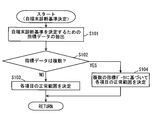
- the self-terminal diagnosis criterion determination process in S10 is a process for determining a normal range for each predetermined diagnosis item based on the index data received from the peripheral vehicle-mounted device 1B.
- FIG. 6 shows an example of a more specific processing procedure of this self-terminal diagnosis criterion determination processing.
- index data as a population for generating a self-terminal diagnosis criterion is extracted from the index data received from the peripheral vehicle-mounted device 1B stored in the memory 11M, and the process proceeds to S102.
- the index data received from another in-vehicle device 1 within the past fixed time (the population adoption time) from the time when the index data generation unit F2 generates the index data is used as the self-terminal diagnosis standard. Extract as a population to decide.
- the length of the population recruitment time is preferably a relatively short time, for example, about the first time or the cycle of transmitting the index data. This is due to the following reason. As described at the beginning, the target vehicle A and the surrounding vehicle B are highly likely to behave with high similarity. In this case, the operation status (detected value, etc.) of the own sensor and the sensor included in the surrounding in-vehicle device 1B It can be expected that the operation situation of the system will also be highly similar.
- the population recruitment time is as short as possible.
- the population adoption time is too short, the number of index data extracted as a population is reduced.
- the population recruitment time may be appropriately determined in view of the above trade-off.
- one index data is used. That is, only one index data is used from one vehicle-mounted device 1 at most.
- a criterion for selecting one index data from the index data may be appropriately designed.
- the newest index data is adopted.
- the index data received within the population adoption time in the past of the time when the index data generation unit F2 generated the index data is adopted as the population, but the present invention is not limited to this.
- the index data received from the time when the index data generation unit F2 generates the index data until the population adoption time elapses may be adopted as the population.
- the index data received within the population adoption time before and after the index data generation unit F2 generates the index data may be adopted as the population.
- S102 it is determined whether or not there are a plurality of index data extracted in S101. If there are a plurality of items, the process proceeds to S104. On the other hand, if there is only one, the process proceeds to S103. If none exists, the self-terminal diagnosis criterion determination process and the self-terminal diagnosis process may be terminated as an error.
- a normal range for each diagnostic item is determined based on the one index data extracted in S101.
- the range in which the maximum value of the detected value for each axial direction of the acceleration sensor 15 is determined to be normal is the index extracted in S101. What is necessary is just to set it as the predetermined
- the upper limit of the normal range with respect to the maximum value of the detected value in the axial direction of the acceleration sensor 15 adds a constant value to the maximum value of the detected value in the axial direction of the acceleration sensor 15 in the extracted index data.
- the lower limit may be a value obtained by subtracting a fixed value from the maximum value of the detected values for each axial direction of the acceleration sensor 15 in the extracted index data.
- the constant value here may be designed as appropriate.
- a range that is ⁇ 30% of the maximum detected value for each axial direction of the acceleration sensor 15 in the extracted index data may be a normal range for the maximum detected value for each axial direction of the acceleration sensor 15.
- the normal ranges for the other diagnostic items are similarly added to or subtracted from a predetermined value set for each diagnostic item with respect to the index value of each item included in the index data extracted in S101, or a predetermined ratio is set. What is necessary is just to be determined by multiplying.
- the process returns to the self-terminal diagnosis process that is the caller process (S11 in FIG. 5).
- a normal range for each diagnostic item is determined based on the plurality of index data extracted in S101.
- the difference between S104 and S103 lies in the difference in whether the population for determining the self-terminal diagnosis criteria is one index data or a plurality of index data.
- a representative value is calculated for each item included in the index data based on the plurality of index data extracted in S101. Since the plurality of index data are data received from different peripheral vehicle-mounted devices 1B, it is naturally assumed that the index values for the same item are different (varied) for each index data.
- the representative value of a certain item is a value representatively representing the value of that item in each of a plurality of index data.
- the representative value of a certain item may be an average value used in statistics or the like, or may be a median value. Moreover, the value which added the standard deviation to the average value, and the value which added twice the standard deviation to the average value may be sufficient. What value should be used as the representative value for each item may be appropriately designed.
- the value of that item in each index data is an average value determined as a population.
- the lower limit of the normal range of each item is a value obtained by subtracting twice the standard deviation from the average value of the item
- the upper limit is a value obtained by adding the value twice the standard deviation to the average value.
- the determination method of the normal range of each item is not limited to the above, and may be appropriately designed.
- the representative value of each item may be an average value or a median value, and thereafter, the upper limit and the lower limit of the normal range may be determined by the same method as in S103 based on the representative value.
- the process returns to the self-terminal diagnosis process (FIG. 5) that is the caller process, and the process proceeds to S11.
- the own terminal diagnosis unit F6 diagnoses the own sensor using the normal range for each diagnosis item determined in S10. That is, it is determined whether or not the value of each item included in the index data generated by the index data generation unit F2 is within the normal range corresponding to the item.
- various normal ranges are determined based on the index data of the vehicle-mounted device 1B existing around the terminal itself. For this reason, for example, when the maximum value of the detected value in the Z-axis direction of the acceleration sensor 15 is not within the corresponding normal range, the operation of the acceleration sensor 15 is performed by the acceleration sensor 15 included in the surrounding in-vehicle device 1. It means that it deviates from the movement tendency.
- the operation of the acceleration sensor 15 deviates from the operation tendency of the acceleration sensor 15 included in the surrounding vehicle-mounted device 1 may be a malfunction of the acceleration sensor 15 or the mounting posture of the vehicle-mounted device 1A with respect to the target vehicle A. This suggests that may not be in the correct mounting posture.
- the detection direction of the Z-axis of the acceleration sensor 15 included in the own terminal is the Z-axis of the acceleration sensor 15 included in the surrounding in-vehicle device 1B. This is because it deviates from the detection direction.
- the acceleration in the Z-axis direction of the acceleration sensor 15 in the own terminal is a relatively large value even though the acceleration acting in the Z-axis direction in the surrounding vehicle-mounted device 1B is a relatively small value. If the acceleration sensor 15 is malfunctioning, or the acceleration acting on the Z-axis direction in a direction different from the original detection direction (height direction) (for example, the longitudinal direction of the vehicle) is detected. Suggests that.
- abnormality determination conditions may be set as appropriate for each sensor. For example, when at least one of the diagnostic items for the sensor deviates from the normal range, it may be determined that an abnormality has occurred in the sensor. Moreover, when the number of items deviating from the normal range among the diagnosis items for the sensor is a predetermined number (for example, three) or more, it may be determined that an abnormality has occurred in the sensor. .
- the target vehicle A behaves differently from the surrounding vehicle B, such as overtaking operation. It may also be included. For this reason, instead of determining that a certain sensor is abnormal by one self-terminal diagnosis process, the self-terminal diagnosis process is performed a plurality of times, and when the abnormality determination condition is satisfied a predetermined number of times, finally, It is good also as an aspect which determines with the abnormality having arisen in the sensor.
- S12 determines whether there is a sensor that is determined to be abnormal. If there is a sensor that is determined to be abnormal, S12 is YES and the process proceeds to S13. On the other hand, as a result of the determination in S12, if there is no sensor determined to be abnormal, S12 is NO and this flow is ended.
- the own terminal abnormality notification unit F9 requests the wide area communication control unit F8 to transmit the own terminal abnormality notification to the center 3. Then, the wide area communication control unit F8 transmits the own terminal abnormality notification to the center 3 based on the request from the own terminal abnormality notification unit F9, and this flow ends.
- the self-terminal diagnosis criterion is determined based on the index data acquired from a plurality of different in-vehicle devices 1B, but is not limited thereto.
- the self-terminal diagnosis standard may be determined based on index data acquired from one on-vehicle device 1B at all times. Moreover, in such a case, it is good also as an aspect which starts an own terminal diagnostic process, when the index data from another vehicle equipment 1B is acquired.
- the processing may be started when a certain in-vehicle device 1B requests to perform another terminal diagnosis process using the peripheral in-vehicle device 1B as a diagnosis target.
- you may start when the roadside machine and road-to-vehicle communication which are not shown in figure are started.
- the peripheral in-vehicle device 1B as the diagnosis target is referred to as the peripheral in-vehicle device 1Bb
- the peripheral in-vehicle devices 1B other than the peripheral in-vehicle device 1Bb are referred to as the peripheral in-vehicle device 1Ba.
- the in-vehicle device 1A in FIG. 8 is the in-vehicle device 1 corresponding to the own terminal.
- the main body that executes the separate terminal diagnosis process is the in-vehicle device 1A.
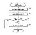
- the normal range determination unit F5 performs another terminal diagnosis criterion determination process and proceeds to S21.
- the different terminal diagnostic criterion determination process in S20 is a process of determining a normal range for each diagnostic item based on the index data received from the in-vehicle device 1Ba.
- the processing procedure of the separate terminal diagnostic criteria determination process is the same as the processing procedure of the self-terminal diagnostic criteria determination process described above, except that index data that can be a population for determining the diagnostic criteria is different. More specifically, in the above-described self-terminal diagnosis criterion determination process, the diagnostic criterion is determined using index data that satisfies a predetermined condition among the index data acquired from the peripheral vehicle-mounted device 1B.
- the diagnostic criterion is determined using index data that satisfies a predetermined condition among the index data acquired from the peripheral vehicle-mounted device 1Ba. That is, among the index data received from the peripheral vehicle-mounted device 1Ba, the index data received from the peripheral vehicle-mounted device 1Ba within the population adoption time in the past from the time when the index data from the peripheral vehicle-mounted device 1Bb is received as the population. adopt.
- the index data of the terminal itself has been generated within the population adoption time in the past from the time of receiving the index data from the peripheral in-vehicle device 1Bb, the index data is also extracted as the population.
- This separate terminal diagnosis reference process is the same as the process procedure of the self-terminal diagnosis reference determination process described above, except for the above differences, and thus a detailed description of the process procedure is omitted.
- the normal range determination unit F5 may determine another terminal diagnosis criterion using index data acquired from the peripheral vehicle-mounted device 1Bb as a diagnosis target.
- the separate terminal diagnosis unit F7 diagnoses the sensor included in the peripheral vehicle-mounted device 1Bb using the normal range for each diagnosis item determined as the separate terminal diagnosis reference in S20. That is, it is determined whether or not the value of each item included in the index data received from the peripheral vehicle-mounted device 1Bb is within the normal range corresponding to the item.
- the separate terminal diagnosis unit F7 determines whether or not an abnormality has occurred in any of the sensors included in the peripheral vehicle-mounted device 1Bb as a result of the determination in S21. That is, as a result of the determination in S21, it is determined whether a certain sensor satisfies a preset abnormality determination condition.
- S22 if there is a sensor that is determined to be abnormal, S22 is YES and the process proceeds to S23. On the other hand, as a result of the determination in S22, if there is no sensor determined to be abnormal, S22 is NO and this flow ends.
- the separate terminal abnormality notification unit F10 requests the wide area communication control unit F8 to transmit the separate terminal abnormality notification to the center 3. Then, the wide area communication control unit F8 transmits another terminal abnormality notification to the center 3 based on the request from the other terminal abnormality notification unit F10, and this flow is finished.
- the different terminal diagnosis criteria can be determined by using the index data of the own terminal in addition to the index data acquired from the other on-vehicle device 1Ba, but is not limited thereto.
- the different terminal diagnosis criteria may be determined based on the index data acquired from the in-vehicle device 1Ba without using the index data of the own terminal.
- the normal range for each index value is determined based on the index value indicating the tendency of the operation of the sensor included in at least one in-vehicle device 1 excluding the diagnostic target (S10, S20), and set as the diagnostic target. It is determined whether or not the index value of the sensor included in the in-vehicle device 1 is within the normal range. Then, when the number or type of index values not within the normal range satisfies a predetermined abnormality determination condition, it is determined that the sensor is not operating normally (S12, S22).
- the above-mentioned external environment represents the environment in which the host vehicle is traveling, and includes the road surface shape, road shape (curvature), road gradient, time zone, weather in which the host vehicle is traveling. And so on. It is assumed that these elements are common to the target vehicle A and the surrounding vehicle B. In connection with it, it is assumed that the influence which those elements have on the detected value of the sensor of each vehicle equipment 1 is also common.
- both the detection value of the sensor to be diagnosed and the detection value of the sensor used to determine the normal range for diagnosing the sensor are detection values that are similarly affected by the external environment. Yes.
- the normal range for diagnosing the sensor is a range in which the influence of the external environment acting on the sensor to be diagnosed is reflected.
- the target vehicle A and the surrounding vehicle B are traveling along the flow of traffic, it is assumed that both of them will behave with high similarity. In particular, when the target vehicle A and the surrounding vehicle B are carrying out a platooning using a follow-up running function that has been spreading in recent years, the tendency is expected to be remarkable.
- the sensors for example, the acceleration sensor 15
- the tendency of the operation of each sensor is highly similar. Can be expected.
- the tendency of the operation of the sensor that detects a certain type of physical state quantity in the in-vehicle device 1 that is the diagnosis target is different from the tendency of the operation of the sensor that detects the same type of physical state quantity in another in-vehicle device 1. If they are different, it means that the sensor of the vehicle-mounted device 1 that is the diagnostic target is not operating normally.
- information used when performing the above-described diagnosis is only various index values determined based on detection values detected by the sensors included in the in-vehicle device 1. That is, information outside the in-vehicle device 1, for example, information such as the road surface shape on which the host vehicle is traveling, the road shape (curvature), the road gradient, the time zone, and the weather is not used.
- the illuminance sensor 17 outputs a relatively large detection value during the daytime, while outputting a relatively small value at night. Therefore, if it is attempted to set a threshold value for determining whether or not the illuminance sensor 17 has a problem with respect to the magnitude of the output value of the illuminance sensor 17, it is necessary to use a threshold value corresponding to the time zone. Along with this, it is necessary for the in-vehicle device 1 to acquire time information or to set a plurality of threshold values according to time zones in advance.
- the output value decreases even when the weather is fine, and the sunrise and sunrise differ according to the season. Therefore, it is necessary to use a value corresponding to the weather and season as the threshold for the illuminance for determining whether or not the illuminance sensor 17 has a problem, and the vehicle-mounted device 1 needs to acquire up to weather information and date information. Occurs.
- the in-vehicle device 1 it is not necessary for the in-vehicle device 1 to acquire time information, date information, and weather information, and it is also necessary to dynamically use thresholds corresponding to those elements. Absent. For example, in the daytime, the illuminance output from the illuminance sensor 17 of the in-vehicle device 1A or the in-vehicle device 1Ba is a sufficiently large value compared to that at night. In such a situation, when the output value of the illuminance sensor 17 included in the in-vehicle device 1Bb is relatively small, it is possible to detect that something is wrong with the illuminance sensor 17 of the in-vehicle device 1Bb.
- the output of the illuminance sensor 17 of the in-vehicle device 1Bb is smaller than that of the surrounding in-vehicle device 1Ba or the own terminal, a cover that shields the illuminance sensor 17 of the in-vehicle device 1Bb from sunlight is attached to the in-vehicle device 1Bb. Or when the illuminance sensor 17 is defective.
- the illuminance sensor 17 of the in-vehicle device 1Bb is used as a diagnosis target is illustrated, but the same applies to the illuminance sensor 17 of the own terminal.
- the operation tendency of the acceleration sensor 15 is affected by the smoothness, gradient, curvature, etc. of the road on which the vehicle in which the vehicle-mounted device 1 is used is traveling.
- the situation in which the acceleration sensor 15 detects the acceleration in the vertical direction is when the host vehicle is traveling on a road with many irregularities or a road on a bridge. While this means that the vehicle is operating normally, if the host vehicle is traveling on a flat road, it means that a problem has occurred.
- the vehicle-mounted device 1 can acquire information related to the road surface condition of the currently traveling road and if a threshold value corresponding to the road surface condition is prepared in advance, the threshold value is set. It can be used to determine whether or not the acceleration sensor 15 is operating normally. However, in that case, it is necessary to acquire information related to the road surface condition of the road on which the vehicle-mounted device 1 is currently traveling, and it is necessary to prepare a plurality of threshold values corresponding to the road surface condition in advance.
- the configuration of the present embodiment there is no need to acquire information on the road surface condition of the road on which the vehicle-mounted device 1 is currently traveling, and a plurality of threshold values corresponding to the road surface condition are set in advance. There is no need to prepare. Therefore, it can be determined whether or not the acceleration sensor 15 is operating properly with a simpler configuration.
- the gyro sensor 16 is affected by the behavior of the vehicle (mounted vehicle) on which the in-vehicle device 1 is mounted. For example, when the vehicle is traveling on an intersection or a curve, a relatively large detection value is output. On the other hand, when the vehicle is traveling straight, the output value is a relatively small value. Should.
- the situation where the gyro sensor 16 outputs a detection value of a predetermined size (including 0) is when the vehicle on which the vehicle-mounted device 1 is mounted is running on a curve or when turning at an intersection. This means that the vehicle is operating normally, while the host vehicle is traveling on a straight road means that a malfunction has occurred.
- the in-vehicle device 1 can acquire information that can specify whether or not the in-vehicle vehicle is traveling straight, the magnitude of the detection value output from the gyro sensor 16 and a preset threshold value are used. It is possible to determine whether or not the gyro sensor 16 is operating normally. However, in that case, the vehicle-mounted device 1 needs to acquire information that can specify whether or not the mounted vehicle is traveling straight.
- the information that can specify whether or not the mounted vehicle is traveling straight includes vehicle information such as the curvature of the road on which the vehicle is traveling, the steering angle, and the traveling speed.
- the in-vehicle device 1 does not need to acquire the various information described above, and it is necessary to prepare a plurality of types of thresholds corresponding to the behavior of the vehicle in advance. Absent. Therefore, it can be determined whether or not the gyro sensor 16 is operating properly with a simpler configuration.
- 1 A of vehicle equipment can diagnose the various sensors with which a self-terminal is equipped with self (that is, self-terminal diagnostic part F6), and by transmitting the parameter
- the center 3 can take measures such as arranging maintenance of the in-vehicle device 1A.
- the case where the vehicle-mounted device 1A cannot communicate with the center 3 corresponds to a case where the wide-area communication device 13 of the vehicle-mounted device 1A is out of order or a case where the wide-area communication device 13 is not provided.
- the in-vehicle device 1 having a function of notifying the center 3 that an abnormality has occurred in a sensor included in a certain in-vehicle device 1 may be present at a certain rate.
- the in-vehicle device 1 to be diagnosed includes at least a detection result acquisition unit F1, an index data generation unit F2, and a narrow area communication control unit F3 having a function of transmitting the index data of the terminal itself. Good.
- the in-vehicle device 1 on the diagnosis side includes at least a narrow area communication control unit F3 having a function of acquiring index data transmitted from the in-vehicle device 1 on the diagnosis side, an index data management unit F4, and a normal range. What is necessary is just to provide the determination part F5, another terminal diagnostic part F7, and the wide area communication control part F8.
- the in-vehicle device 1 on the diagnosing side can diagnose the in-vehicle device 1 on the diagnosing side, but cannot diagnose itself or have it diagnosed. Therefore, the in-vehicle device 1 on the diagnosis side includes a detection result acquisition unit F1 and an index data generation unit F2 in addition to the above-described minimum configuration, and the narrow area communication control unit F3 further includes a local communication control unit F3. It is preferable to have a function of transmitting index data.
- the own terminal diagnosis unit F6 is not provided, it is possible to have the diagnosis performed by transmitting the own index data to the in-vehicle device 1 on the other diagnosis side. Therefore, the own terminal diagnostic unit F6 may not be provided. That is, the own terminal diagnosis unit F6 is an arbitrary element.
- the case where the sensor with which the vehicle equipment 1 is not operating normally may include the case where the vehicle equipment 1 is not attached to the vehicle in a correct posture.
- the correct posture here refers to a predetermined mounting posture.
- the self-terminal diagnosis unit F6 may determine whether or not the mounting posture of the self-terminal is the correct posture. Further, the separate terminal diagnosis unit F7 may determine whether or not the in-vehicle device 1Bb to be diagnosed is attached in a correct posture in the vehicle Bb in which the in-vehicle device 1Bb is mounted.
- the self-terminal diagnosis unit F6 of the in-vehicle device 1A determines whether or not the mounting posture of the self-terminal is the correct posture. An embodiment is illustrated.
- the relationship between the traveling state of the target vehicle A and the detected values in the three axial directions output from the acceleration sensor 15 of the in-vehicle device 1A will be described.
- the magnitude of the acceleration detected by the acceleration sensor 15 is a fixed value, That is, it becomes equal to gravitational acceleration ( ⁇ 9.8 m / sec ⁇ 2) (including substantially coincidence).
- the gravitational acceleration appears after being decomposed in the three axial directions of the acceleration sensor 15 according to the posture of the vehicle-mounted device 1 with respect to the horizontal plane.
- the detected value for each axial direction of the acceleration sensor 15 when the vehicle is stopped represents the attitude of the vehicle-mounted device 1 with respect to the horizontal plane.
- the horizontal plane here refers to a plane perpendicular to the direction in which gravity acts.
- the in-vehicle device 1A can recognize that the target vehicle A is stopped, the detected value for each axial direction of the acceleration sensor 15 when the target vehicle A is stopped is A method of determining whether or not the mounting posture of the in-vehicle device 1A with respect to the target vehicle A is correct depending on whether or not the value is within a predetermined range.
- the output value for each axial direction of the acceleration sensor 15 is not always the same. This is because when the target vehicle A exists on a road with a gradient such as a slope, the ratio of the output values of the acceleration sensor 15 in the axial direction changes due to the influence of the road gradient.
- the vehicle-mounted device 1A is configured to recognize that the target vehicle A is stopped, the vehicle-mounted device 1A is in a correct posture using a predetermined threshold value. It is difficult to accurately determine whether it is attached.
- the target vehicle A exists on a road with a slope
- the surrounding vehicle B also exists on a road with a similar slope. That is, the influence of the road gradient is received not only by the acceleration sensor 15 of the terminal itself but also by the acceleration sensor 15 of the peripheral vehicle-mounted device 1B.
- the self-terminal diagnosis unit F6 detects the detected values for each axial direction output from the stopped acceleration sensor 15 and the three axial directions output from the acceleration sensor 15 included in the stopped on-vehicle device 1B. By comparing the detected value with each other, it is determined whether or not the mounting posture of the terminal itself is correct.
- the in-vehicle device diagnosis system 100 in the second modification may be configured as follows, for example.
- the controller 11 of the in-vehicle device 1A includes a stop determination unit F11 that determines whether or not the target vehicle A is stopped.
- the stop determination unit F11 may determine based on the reception status of the GNSS receiver 14, for example.
- the distance between the GNSS receiver 14 and the GNSS satellite changes.
- the frequency of the carrier wave transmitted from the GNSS satellite becomes higher than the prescribed frequency due to the Doppler effect.
- the frequency of the carrier wave transmitted from the GNSS satellite becomes lower than the specified frequency. It is known that a change in the reception frequency of a signal transmitted from a GNSS satellite due to such a Doppler effect can be observed as a change in the phase of the received signal.
- the GNSS receiver 14 when the GNSS receiver 14 is receiving a signal from at least one GNSS satellite and no phase change due to the Doppler effect is observed in the received signal from any GNSS satellite, It is determined that the vehicle A is stopped. In addition, when the GNSS receiver 14 receives a signal from at least one GNSS satellite and observes a phase change due to the Doppler effect in a received signal from any of the GNSS satellites being captured. May determine that the target vehicle A is not stopped. Note that when the GNSS receiver 14 does not supplement any GNSS satellite, the above-described determination may not be performed or it may be determined that the vehicle is not stopped.
- the stop determination unit F11 also moves the target vehicle A when the current position information output from the GNSS receiver 14 indicates the same position (including substantially the same) as the position information output last time. It may be determined that it is not.
- the index data generation unit F2 is provided for each axial direction output by the acceleration sensor 15 while the determination is maintained.
- the detection value is included in the index data and transmitted.
- the detected value for each axial direction output by the acceleration sensor 15 while the vehicle is stopped included in the index data is referred to as posture information.
- the in-vehicle device 1B mounted on the peripheral vehicle B similarly determines whether or not the vehicle on which the terminal is mounted is stopped. When it is determined that the vehicle is provided with a stop determination unit F11 and is further stopped by the stop determination unit F11, index data including posture information is transmitted.
- the normal range determination unit F5 determines a normal range for the mounting posture based on the posture information.
- the normal range for the mounting posture may be a range in which a predetermined margin (for example, ⁇ 20%) is given to the detection value for each axial direction included in the received posture information.
- the own terminal diagnosis unit F6 is a case where posture information is included in the index data generated by the index data generation unit F2 of the own terminal, and the normal range determination unit F5 acquires the posture acquired from the peripheral vehicle-mounted device 1B.
- the normal range for the mounting posture is determined based on the information, it is determined whether or not the detected value for each axial direction indicated in the posture information of the terminal itself is within the normal range.
- the own terminal abnormality notification unit F9 performs processing for notifying the center 3 that the attachment posture of the own terminal is not the correct posture.
- the configuration of the second modification it is possible to determine whether or not the mounting posture of the terminal itself is correct in consideration of the road gradient.
- the own terminal diagnosis unit F6 determines the mounting posture of the own terminal has been exemplified, but the method for determining whether or not the mounting posture of the peripheral vehicle-mounted device 1Bb as a predetermined diagnostic target is the correct posture is also the same. It is.
- the normal range determination unit F5 receives index data including posture information from the peripheral vehicle-mounted device 1Ba
- the normal range determination unit F5 may determine a normal range for the mounting posture based on the posture information. Further, the normal range for the mounting posture may be determined based on the posture information included in the index data generated by the index data generation unit F2 of the terminal itself.
- the separate terminal diagnosis unit F7 compares the posture information included in the index data acquired from the peripheral on-vehicle device 1Bb as the diagnosis target with the normal range with respect to the mounting posture determined by the normal range determination unit F5. What is necessary is just to determine whether 1Bb is attached with the correct attitude
- each vehicle-mounted device 1 includes the GNSS receiver 14 and the stop determination unit F11, and the mounting posture of the vehicle-mounted device 1 is mounted in a correct posture using the result detected by the acceleration sensor 15 while the vehicle is stopped.
- the present invention is not limited to this.
- the mounting posture of the terminal and the peripheral vehicle-mounted device 1B with respect to the vehicle is the correct posture using the median value for each axial direction of the acceleration sensor 15 included in the index data. It may be determined whether or not.
- a mode in which the self-terminal diagnosis unit F6 of the in-vehicle device 1A determines whether or not the mounting posture of the self-terminal is the correct posture.
- the acceleration detected by the acceleration sensor 15 is not detected.
- the magnitude (hereinafter, the detected acceleration absolute value) is equal to the gravitational acceleration (including substantially coincidence).
- the detected acceleration absolute value is equal to the gravitational acceleration even when the target vehicle A is moving straight ahead at a constant speed.
- the target vehicle A may stop or move at a constant speed in a straight line.
- the detected acceleration absolute value is the square root of the sum of the squared values of the detected values for each axial direction.
- the target vehicle A does not always stop or move at a constant linear velocity.
- the detected acceleration absolute value may be equal to the gravitational acceleration due to the force generated due to acceleration / deceleration or turning of the target vehicle A. It is.
- the detected acceleration absolute value of the acceleration sensor 15 provided in each of the own terminal and the plurality of vehicle-mounted devices 1B existing around the own terminal is equal to (or a part of) the acceleration of gravity.
- the target vehicle A and the surrounding vehicle B can be regarded as stopping or moving at a constant linear velocity.
- the target vehicle A and the surrounding vehicle B are output from the acceleration sensor 15 when the vehicle is stopped or is moving at a constant linear velocity.
- the detection values for each horizontal plane affected by the road gradient are as described above.
- position of the vehicle equipment 1 is represented.
- the self-terminal diagnosis unit F6 compares the detection results of the acceleration sensors 15 when the detected acceleration absolute values of the self-terminal and the peripheral vehicle-mounted device 1B are equal to the gravitational acceleration, respectively. Thus, it can be determined whether or not the mounting posture of the terminal itself is correct.
- the configuration of the in-vehicle device diagnosis system 100 in the third modification may be as follows. Whenever the detection result is acquired from the acceleration sensor 15, the detection result acquisition unit F1 calculates a detection acceleration absolute value from the detection result and stores it in the memory 11M. Then, the index data generation unit F2 generates index data including a detected acceleration absolute value corresponding to the latest detection result and a detected value for each axial direction that is the basis of the detected acceleration absolute value.
- the self-terminal diagnosis unit F6 determines whether there are a plurality of index data extracted in S101 of FIG. 6 and the absolute values of the detected accelerations are all (or a certain ratio or more) equal to the gravitational acceleration. Determine.
- the detected acceleration absolute values of the plurality of index data are equal to the gravitational acceleration, it is further determined whether or not the detected acceleration absolute values in the index data of the terminal itself are also equal to the gravitational acceleration.
- the detected acceleration absolute value in the index data of the own terminal is also equal to the gravitational acceleration
- the detected value for each axial direction included in the index data of the own terminal and the axis included in the index data acquired from the peripheral vehicle-mounted device 1B The detected values for each direction are compared.
- the own terminal abnormality notification unit F9 performs processing for notifying the center 3 that the attachment posture of the own terminal is not the correct posture.
- the self terminal diagnosis unit F6 has exemplified the mode of determining whether or not the mounting posture of the self terminal is the correct posture.
- the peripheral in-vehicle device 1Bb as the diagnosis target is correctly mounted by the separate terminal diagnosis unit F7.
- the determination as to whether or not the posture is the same as the procedure described above by replacing the index data as the diagnosis target with the index data acquired from the in-vehicle device 1Bb as the diagnosis target from the index data of the own terminal Just go to
- the population of the index data for determining the self-terminal diagnosis criteria is received from another vehicle-mounted device 1B within a certain time that is determined based on the time when the index data generation unit F2 generates the index data.
- index data it is not limited to this.
- index data acquired from the in-vehicle device 1B existing within a certain distance from the own terminal may be adopted as a population.
- the target vehicle A and the surrounding vehicle B are likely to behave with high similarity (acceleration / deceleration and turning), but among them, the similarity between the surrounding vehicle B and the target vehicle A is similar. This is because the degree is expected to be high. That is, by adopting the index data received from the in-vehicle device 1B existing within a certain distance from the own terminal among the peripheral in-vehicle devices 1B as a population for determining the own terminal diagnosis criteria, Accuracy can be improved.
- This modification 4 may be configured as follows, for example. First, the narrow area communication control unit F3 of each vehicle-mounted device 1 has position information (latitude, longitude, height) indicating the current position determined based on the terminal ID and the detection result of the GNSS receiver 14 for the index data. And a header including
- the narrow area communication control unit F3 acquires data including the index data transmitted from another vehicle-mounted device 1B, the terminal ID representing the index data and the transmission-source vehicle-mounted device 1 from the received data. And the position information is extracted and provided to the index data management unit F4.
- the index data management unit F4 When the index data management unit F4 acquires the index data, the terminal ID, and the position information from the narrow area communication control unit F3, the index data management unit F4 stores the index data, the position information, and the terminal ID in the memory 11M in association with each other.
- the normal range determination unit F5 receives the index data received from another vehicle-mounted device 1B within the past and population adoption time at the time when the index data generation unit F2 generated the index data in the self-terminal diagnosis criterion determination process.
- the index data received from the in-vehicle device 1B existing within a certain distance from the own terminal may be adopted as a population for determining the own terminal diagnostic criteria.
- the current location of the terminal itself may be specified based on the location information provided from the GNSS receiver 14. Further, the distance between the own terminal and each in-vehicle device 1B is calculated from the latitude and longitude included in the position information associated with the index data received from the in-vehicle device 1B and the difference between the latitude and longitude of the own terminal. It ’s fine.
- the fixed distance may be set to 25 m or 50 m, for example.
- the normal range determination unit F5 received from another vehicle-mounted device 1Ba within the past and the population adoption time at the time of receiving the index data from the vehicle-mounted device 1Bb as the diagnosis target in the different terminal diagnosis criterion determination process.
- the index data received from the in-vehicle device 1Ba existing within a certain distance from the current position of the in-vehicle device 1Bb is further extracted as a population.
- the current position of the terminal is within a certain distance from the current position of the in-vehicle device 1Bb, and within the past population adoption time at the time when the index data from the in-vehicle device 1Bb is received, the index data generation unit F2 When index data is generated, the index data may be included as a population.
- the normal range determination unit F5 determines various diagnostic criteria among the index data acquired from the in-vehicle device 1B and the index data of the own terminal based on the distance from the in-vehicle device 1 as the diagnosis target.
- the present invention is not limited to this.
- the normal range determination unit F5 may employ, as a population, index data acquired from the in-vehicle device 1 that exists at the same height as the in-vehicle device 1 that is the diagnosis target.
- the index data from the vehicle-mounted device 1 whose height is more than a certain value away from the vehicle-mounted device 1 that is the diagnostic target is the mother for determining the diagnostic criteria. It is good also as an aspect which is not employ
- the fifth modification may be realized in the same manner as the fourth modification. That is, the height at which the peripheral vehicle-mounted device 1B is located may be specified based on the position information associated with the index data, and the height at which the terminal is located is based on the detection result of the GNSS receiver 14. Should be specified.
- the normal range determination unit F5 determines a diagnostic criterion based on the index data acquired from the in-vehicle device 1 moving in the same direction (including substantially the same) as the moving direction of the in-vehicle device 1 as a diagnosis target. Also good. As described at the beginning, the target vehicle A and the surrounding vehicle B are likely to behave with high similarity (acceleration / deceleration and turning), but this is not the case for the vehicle-mounted device 1 having a different moving direction.
- the behavior differs between a vehicle equipped with the vehicle-mounted device 1 as a diagnostic target and a vehicle traveling in the opposite lane of the lane in which the vehicle travels or a vehicle moving in another direction near the intersection. More likely to be. Therefore, the index data from the in-vehicle device 1 that moves in a direction different from the moving direction of the in-vehicle device 1 as a diagnosis target is not adopted as a population for determining a diagnostic criterion, thereby improving the determination accuracy. be able to.
- the moving direction of the in-vehicle device 1 may be specified based on, for example, the Doppler effect of the signal received by the GNSS receiver 14 described in Modification 3.
- a method for obtaining a moving direction in a horizontal plane from a change in frequency generated in a signal received by the GNSS receiver 14 due to the Doppler effect is a well-known technique.
- the modified example 6 may be configured as follows. First, the narrow area communication control unit F3 of each in-vehicle device 1 indicates the moving direction of the own terminal determined based on the terminal ID and the frequency change of the received signal of the GNSS receiver 14 for the index data to be transmitted. A header including information is added and transmitted.
- the narrow area communication control unit F3 acquires data including the index data transmitted from another vehicle-mounted device 1, the index data and the terminal ID representing the vehicle-mounted device 1 that is the transmission source are received from the received data. And the moving direction are extracted and provided to the index data management unit F4.
- the index data management unit F4 acquires the index data, the terminal ID and the movement direction associated with the index data from the narrow area communication control unit F3, the index data and the movement direction are stored in the memory 11M in association with the terminal ID. To do.
- the normal range determination unit F5 employs, as a population, the index data acquired from the in-vehicle device 1 that is moving in the same direction as the moving direction of the in-vehicle device 1 that is the diagnosis target.
- the index data acquired from the in-vehicle device 1 having the same moving direction of the in-vehicle device 1 as the diagnosis target, and the index data of the in-vehicle device 1 as the diagnosis target is acquired as in the above-described embodiment.
- the diagnostic criteria may be determined based on the index data acquired within the past and population recruitment time.
- a sensor included in a certain in-vehicle device 1 is normal may be determined by a roadside device that is performing road-to-vehicle communication with the in-vehicle device 1.
Landscapes
- Physics & Mathematics (AREA)
- General Physics & Mathematics (AREA)
- Traffic Control Systems (AREA)
- Arrangements For Transmission Of Measured Signals (AREA)
Abstract
Description
Environment)の規格に準拠して、車車間通信や路車間通信を実施すればよい。以降において車載機1と路側機とを区別しない場合には、単に通信端末と称する。
ことができるようになっている。
まずは、車載機診断システム100の概要について述べる。車載機診断システム100が備える複数の車載機1のそれぞれは、自端末に作用する加速度や回転角速度といった、所定の物理状態量を検出するセンサ機とも言及されるセンサ(つまり加速度センサやジャイロセンサなど)を備えている。尚、対象車両Aのセンサは、センサ機とも言及するのに対して、周辺車両Bのセンサを別センサあるいは別センサ機とも言及される。そして、各車載機1は車車間通信によって、それぞれ自端末が備える種々のセンサの動作状況を示すデータ(後述の指標データ)を送信するとともに、自端末周辺に存在する別の車載機1が送信した指標データを受信する。つまり、車載機1Aは、自端末の指標データ(自機指標データとも言及される)を送信するとともに、周辺車載機1Bが送信した指標データ(別機指標データとも言及される)を受信する。
次に、図2を用いて、車載機1の概略的な構成について説明を行う。図2に示すように車載機1は、コントローラ11、狭域通信器12、広域通信器13、GNSS受信機14、加速度センサ15、ジャイロセンサ16、及び照度センサ17を備えている。コントローラ11と、狭域通信器12、広域通信器13、GNSS受信機14、加速度センサ15、ジャイロセンサ16、及び照度センサ17のそれぞれとは、相互通信可能に接続されている。
センター3は、広域通信網2に接続しており、車載機診断システム100が備える車載機1と広域通信網2を介して相互通信を実施する。センター3は、或る車載機1から自端末異常通知を受信した場合には、例えば、その車載機1に対してメンテナンスを行うためのスタッフの手配を行う。また、予め車載機1の端末IDとユーザの連絡先(例えばメールアドレス)と対応付けたデータを備えている場合には、その連絡先に、車載機1のセンサが正常に動作していない旨を通知してもよい。
次に、図5に示すフローチャートを用いて、車載機1のコントローラ11が、自センサを診断する処理(自端末診断処理とする)について説明する。便宜上、当該処理を行う車載機1と、別の車載機1とを区別するため、車載機1Aを当該処理の主体として説明する。
次に、図7に示すフローチャートを用いて、コントローラ11が、周辺車載機1Bが備えるセンサを診断する処理(別端末診断処理とする)について説明する。このフローチャートは、任意の周辺車載機1Bから指標データを取得したことをトリガとして開始されれば良い。もちろん、自端末診断処理を開始する条件は適宜、設計されれば良く、例えば指標データ生成部F2が指標データを生成した場合であってもよい。
ある。
以上の構成では、診断ターゲットとする車載機1が備えるセンサの動作の傾向を示す指標値と、診断ターゲットを除く少なくとも1つの車載機1が備えるセンサの動作の傾向を示す指標値に基づいて定まる診断基準とを比較することで、診断ターゲットとする車載機1が備えるセンサが正常であるか否かを判定する。
作の傾向と異なる場合には、その診断ターゲットとする車載機1のそのセンサが正常に動作していないことを意味する。
以上では、車載機診断システム100が備える車載機1を何れも同様の機能を備えるものとしたが、これに限らない。診断される側の車載機1と、診断する側の車載機1とで、備えるべき機能は異なる。
車載機1が備えるセンサが正常に動作していない場合とは、車載機1が車両に対して、正しい姿勢で取り付けられていない場合も含みうる。ここでの正しい姿勢とは、予め定められている取付姿勢を指す。
上述の変形例2では、各車載機1がGNSS受信機14及び停車判定部F11を備え、停車中に加速度センサ15が検出した結果を用いて、車載機1の取付姿勢が正しい姿勢で取り付けられているか否かを検出する態様を例示したが、これに限らない。
前述の実施形態では、自端末診断基準を決定するための指標データの母集団を、指標データ生成部F2が指標データを生成した時点を基準として定まる一定時間内に別の車載機1Bから受信した指標データとしたが、これに限らない。
上述の変形例4では、診断ターゲットとする車載機1からの距離に基づいて、車載機1Bから取得した指標データや自端末の指標データのうち、正常範囲決定部F5が種々の診断基準を決定するために用いる指標データを取捨選択する態様を例示したが、これに限らない。例えば、正常範囲決定部F5は、診断ターゲットとする車載機1と等しい高さに存在する車載機1から取得した指標データを母集団として採用してもよい。
さらに、正常範囲決定部F5は、診断ターゲットとする車載機1の移動方向と等しい方向(略一致も含む)に移動している車載機1から取得した指標データに基づいて診断基準を決定してもよい。冒頭でも述べた通り、対象車両Aと周辺車両Bとは、類似性の高い挙動(加減速や旋回)をする可能性が高いが、移動方向が異なる車載機1については、その限りではない。
以上では、車載機1が別端末診断部F7を備える態様を例示したが、これに限らない。路側機が、車載機1から送信される指標データを受信する狭域通信制御部F3、指標データ管理部F4、正常範囲決定部F5、別端末診断部F7、及び広域通信制御部F8を備える態様としてもよい。
Claims (9)
- 対象車両とその周辺の複数の周辺車両を含む、複数のホスト車両の、それぞれで用いられ、車車間通信を実施する車載機であって、
各車載機は、
車車間通信による情報の送受信を実施する無線通信器(12)と、
各車載機に作用する所定の物理状態量を検出するセンサ機(15、16、17)と、
前記センサ機の検出結果に基づいて、前記センサ機の動作状況を示す指標データを生成する指標データ生成部(F2)と、を備え、
前記指標データ生成部が生成した前記指標データを前記無線通信器を介して送信させ、
前記対象車両に用いる前記車載機であるところの対象車載機は、更に、
前記複数の周辺車両の前記車載機であるところの複数の周辺車載機から送信された前記指標データであるところの別機指標データを、前記無線通信器を介して取得する通信処理部(F3)と、
前記通信処理部が取得した前記別機指標データに基づいて、前記複数の周辺車載機のうち、所定の診断ターゲットとするターゲット周辺車載機が備える前記センサ機であるところの、別センサ機が正常に動作しているか否かを判定するための判定基準である別機判定基準を逐次決定する判定基準決定部(F5)と、
前記判定基準決定部が決定した前記別機判定基準と、前記ターゲット周辺車載機から取得した前記別機指標データとを比較することによって、前記ターゲット周辺車載機が備える前記別センサ機が正常に動作しているか否かを判定する別機診断部(F7)と、を備える
車載機。 - 対象車両とその周辺の少なくとも一つの周辺車両を含む、複数のホスト車両の、それぞれで用いられ、車車間通信を実施する車載機であって、
各車載機は、
車車間通信による情報の送受信を実施する無線通信器(12)と、
各車載機に作用する所定の物理状態量を検出するセンサ機(15、16、17)と、
前記センサ機の検出結果に基づいて、前記センサ機の動作状況を示す指標値を含む指標データを生成する指標データ生成部(F2)と、を備え、
前記指標データ生成部が生成した前記指標データを前記無線通信器を介して送信させ、
前記対象車両で用いられる前記車載機であるところの対象車載機は、更に、
前記少なくとも一つの周辺車両の前記車載機であるところの少なくとも一つの周辺車載機から送信された前記指標データであるところの別機指標データを、前記無線通信器を介して取得する通信処理部(F3)と、
前記通信処理部が取得した前記別機指標データに基づいて、前記対象車載機が備える前記センサ機が正常に動作しているか否かを判定するための判定基準である自機判定基準を逐次決定する判定基準決定部(F5)と、
前記判定基準決定部が決定した前記自機判定基準と、前記対象車載機の前記指標データであるとことの自機指標データとを比較することによって、前記対象車載機の前記センサ機が正常に動作しているか否かを判定する自機診断部(F6)と、を備える
車載機。 - 請求項2において、
前記対象車載機において、
前記判定基準決定部は、前記通信処理部が取得した前記別機指標データに基づいて、前記少なくとも一つの周辺車載機のうち、所定の診断ターゲットとするターゲット周辺車載機が備える前記センサ機であるところの別センサ機が正常に動作しているか否かを判定するための判定基準である別機判定基準を逐次決定し、
前記判定基準決定部が決定した前記別機判定基準と、前記ターゲット周辺車載機から前記通信処理部が取得した前記別機指標データとを比較することによって、前記ターゲット周辺車載機が備える前記別センサ機が正常に動作しているか否かを判定する別機診断部(F7)と、を備える
車載機。 - 請求項3において、
前記対象車載機は、
外部に離れて設けられているセンター(3)と広域通信網を介した通信を行う広域通信器(13)と、
前記別機診断部によって前記ターゲット周辺車載機が備える前記別センサ機が正常に動作していないと判定された場合に、前記広域通信器を介して、前記ターゲット周辺車載機の前記別センサ機が正常に動作していないことを前記センターに通知する別機異常通知部(F10)と、を備える
車載機。 - 請求項3又は4において、
各ホスト車両で用いられる各車載機は、
各車載機自体の現在位置を検出し、その検出した現在位置を示す位置情報を逐次出力する位置情報出力器(14)を備え、
前記位置情報出力器が出力する位置情報は、所定の基準面に対して各車載機が位置する高さを示す高さ情報を含み、
前記指標データを、前記無線通信器を介して、送信する場合には、前記位置情報出力器によって出力された位置情報と対応付けて送信し、
前記対象車載機において、
前記通信処理部は、前記少なくとも一つの周辺車載機から送信された、その現在位置を示す位置情報と対応付けられた前記別機指標データを取得し、
前記判定基準決定部は、前記少なくとも一つの周辺車載機のうち、前記ターゲット周辺車載機が位置する高さと等しい高さに位置する前記少なくとも一つの周辺車載機から取得した前記別機指標データに基づいて前記別機判定基準を決定する
車載機。 - 請求項2から5の何れか1項において、
前記対象車載機は、
外部に離れて設けられているセンター(3)と広域通信網を介した通信を行う広域通信器(13)と、
前記自機診断部によって前記センサ機が正常に動作していないと判定された場合に、前記広域通信器を介して、前記対象車載機の前記センサ機が正常に動作していないことを前記センターに通知する自機異常通知部(F9)と、を備える
車載機。 - 請求項6において、
各ホスト車両に用いる各車載機は、
前記センサ機は、互いに直交する3つの軸方向に作用する加速度をそれぞれ検出する加速度センサを含み、
前記指標データは、前記加速度センサが検出した軸方向毎の加速度を含み、
前記対象車載機において、
前記判定基準決定部は、前記少なくとも一つの周辺車載機から取得した前記別機指標データに含まれる、前記軸方向毎の加速度に基づいて、前記対象車載機自体が前記車両に対して予め定められている姿勢で取り付けられているか否かを判定するための判定基準を決定し、
前記自機診断部は、前記判定基準決定部によって決定された判定基準と、前記指標データに含まれる前記軸方向毎の加速度とを比較することによって、前記対象車載機自体が前記対象車両に対して予め定められている姿勢で取り付けられているか否かを判定し、
前記自機異常通知部は、前記自機診断部によって前記対象車載機自体が前記対象車両に対して予め定められている姿勢で取り付けられていないと判定された場合には、前記広域通信器を介して、前記対象車載機が前記対象車両に対して予め定められている姿勢で取り付けられていないことを前記センターに通知する
車載機。 - 請求項2から7の何れか1項において、
各ホスト車両に用いる各車載機は、
各車載機自体の現在位置を検出し、その検出した現在位置を示す位置情報を逐次出力する位置情報出力器(14)を備え、
前記位置情報出力器が出力する位置情報は、所定の基準面に対して各車載機自体が位置する高さを示す高さ情報を含み、
前記指標データを送信する場合には、前記位置情報出力器によって出力された位置情報と対応付けて送信し、
前記対象車載機において、
前記通信処理部は、前記少なくとも一つの周辺車載機から送信された、その現在位置を示す位置情報と対応付けられた前記別機指標データを取得し、
前記判定基準決定部は、前記少なくとも一つの周辺車載機のうち、前記対象車載機が位置する高さと等しい高さに位置する前記少なくとも一つの周辺車載機から取得した前記別機指標データに基づいて前記自機判定基準を決定する
車載機。 - 対象車両とその周辺の少なくとも一つの周辺車両を含む複数のホスト車両のそれぞれに搭載される、複数の車載機(1)を備える車載機診断システムであって、
各車載機は、
車車間通信による情報の送受信を実施する無線通信器(12)と、
各車載機自体に作用する所定の物理状態量を検出するセンサ機(15、16、17)と、
前記センサ機の検出結果に基づいて、前記センサ機の動作状況を示す指標値を含む指標データを生成する指標データ生成部(F2)と、
前記指標データ生成部が生成した前記指標データを前記無線通信器に送信させるとともに、車両前記少なくとも一つの周辺車両の前記車載機であるところの少なくとも一つの周辺車載機から送信された前記指標データであるところの別機指標データを、前記無線通信器を介して取得する通信処理部(F3)と、
前記別機指標データに基づいて、前記少なくとも一つの周辺車載機のうち、所定の診断ターゲットとするターゲット周辺車載機が備える前記センサ機であるところの別センサ機が正常に動作しているか否かを判定するための判定基準である別機判定基準を逐次決定する判定基準決定部(F5)と、
前記判定基準決定部が決定した前記別機判定基準と、前記ターゲット周辺車載機から前記通信処理部が取得した前記別機指標データとを比較することによって、前記ターゲット周辺車載機が備える前記別センサ機が正常に動作しているか否かを判定する別機診断部(F7)と、を備える
車載機診断システム。
Priority Applications (4)
| Application Number | Priority Date | Filing Date | Title |
|---|---|---|---|
| SG11201703173QA SG11201703173QA (en) | 2015-01-09 | 2015-12-22 | In-vehicle unit and in-vehicle unit diagnosis system |
| CN201580071887.6A CN107111935B (zh) | 2015-01-09 | 2015-12-22 | 车载设备、车载设备诊断系统 |
| DE112015005917.2T DE112015005917B4 (de) | 2015-01-09 | 2015-12-22 | Fahrzeugbordeinheit und Fahrzeugbordeinheitdiagnosesystem |
| US15/537,192 US10332321B2 (en) | 2015-01-09 | 2015-12-22 | In-vehicle unit and in-vehicle unit diagnosis system |
Applications Claiming Priority (2)
| Application Number | Priority Date | Filing Date | Title |
|---|---|---|---|
| JP2015-003462 | 2015-01-09 | ||
| JP2015003462A JP6485049B2 (ja) | 2015-01-09 | 2015-01-09 | 車載機、車載機診断システム |
Publications (1)
| Publication Number | Publication Date |
|---|---|
| WO2016110915A1 true WO2016110915A1 (ja) | 2016-07-14 |
Family
ID=56355644
Family Applications (1)
| Application Number | Title | Priority Date | Filing Date |
|---|---|---|---|
| PCT/JP2015/006364 Ceased WO2016110915A1 (ja) | 2015-01-09 | 2015-12-22 | 車載機、車載機診断システム |
Country Status (6)
| Country | Link |
|---|---|
| US (1) | US10332321B2 (ja) |
| JP (1) | JP6485049B2 (ja) |
| CN (1) | CN107111935B (ja) |
| DE (1) | DE112015005917B4 (ja) |
| SG (1) | SG11201703173QA (ja) |
| WO (1) | WO2016110915A1 (ja) |
Cited By (2)
| Publication number | Priority date | Publication date | Assignee | Title |
|---|---|---|---|---|
| CN109643407A (zh) * | 2016-08-10 | 2019-04-16 | 三菱电机株式会社 | 列车设备管理装置和列车设备管理程序 |
| US12236721B2 (en) * | 2022-02-21 | 2025-02-25 | Toyota Jidosha Kabushiki Kaisha | Vehicle and autonomous driving kit |
Families Citing this family (30)
| Publication number | Priority date | Publication date | Assignee | Title |
|---|---|---|---|---|
| JP6485049B2 (ja) * | 2015-01-09 | 2019-03-20 | 株式会社デンソー | 車載機、車載機診断システム |
| JP6398739B2 (ja) * | 2015-01-19 | 2018-10-03 | 株式会社デンソー | 車載機、車載機診断システム |
| JPWO2018155142A1 (ja) * | 2017-02-21 | 2019-07-11 | 日立オートモティブシステムズ株式会社 | 車両制御装置 |
| US10790945B2 (en) * | 2017-03-23 | 2020-09-29 | Qualcomm Incorporated | Methods to mitigate inter-platoon interference |
| EP3393100A1 (en) * | 2017-04-20 | 2018-10-24 | Gemalto Sa | A method for managing the reputation level of a communication device |
| JP6638695B2 (ja) | 2017-05-18 | 2020-01-29 | トヨタ自動車株式会社 | 自動運転システム |
| JP6942413B2 (ja) * | 2017-06-21 | 2021-09-29 | アルパイン株式会社 | 通信装置、通信システム、及び通信制御方法 |
| KR102309438B1 (ko) * | 2017-06-23 | 2021-10-07 | 현대자동차주식회사 | 차량 검사 시스템, 차량 및 차량의 제어 방법 |
| JP7214640B2 (ja) * | 2017-09-11 | 2023-01-30 | ソニーグループ株式会社 | 管理装置、車両、検査装置、並びに、車両検査システムおよびその情報処理方法 |
| JP7071998B2 (ja) * | 2017-12-15 | 2022-05-19 | パナソニック インテレクチュアル プロパティ コーポレーション オブ アメリカ | 車載ネットワーク異常検知システム及び車載ネットワーク異常検知方法 |
| JP7013993B2 (ja) * | 2018-03-26 | 2022-02-01 | トヨタ自動車株式会社 | 診断装置及び診断方法 |
| WO2019193628A1 (ja) * | 2018-04-02 | 2019-10-10 | 三菱電機株式会社 | クライアント装置、データ送信方法及びデータ収集システム |
| JP6988674B2 (ja) * | 2018-05-07 | 2022-01-05 | トヨタ自動車株式会社 | 診断装置、診断システム、及び診断方法 |
| JP7028051B2 (ja) * | 2018-05-07 | 2022-03-02 | トヨタ自動車株式会社 | 診断装置、診断システム、及び診断方法 |
| US10902726B2 (en) * | 2018-08-23 | 2021-01-26 | Intel Corporation | Rogue vehicle detection and avoidance |
| JP7136035B2 (ja) * | 2018-08-31 | 2022-09-13 | 株式会社デンソー | 地図生成装置及び地図生成方法 |
| US20200074761A1 (en) * | 2018-08-31 | 2020-03-05 | Denso Ten Limited | On-vehicle device, data collection system, and data collection apparatus |
| KR102085917B1 (ko) * | 2018-09-28 | 2020-03-06 | 현대오트론 주식회사 | 타 차량의 센서 데이터를 이용하는 차량 시스템 및 차량 제어 방법 |
| JP7099354B2 (ja) * | 2019-02-15 | 2022-07-12 | トヨタ自動車株式会社 | 運転支援装置 |
| JP7382791B2 (ja) * | 2019-10-30 | 2023-11-17 | 株式会社日立製作所 | 異常判定装置、車両支援システム |
| EP3855205A1 (en) * | 2020-01-22 | 2021-07-28 | Zenuity AB | Perception performance evaluation of a vehicle adas or ads |
| US11597393B2 (en) | 2020-03-26 | 2023-03-07 | Intel Corporation | Systems, methods, and devices for driving control |
| JP2021196782A (ja) * | 2020-06-12 | 2021-12-27 | 株式会社オートネットワーク技術研究所 | 車載装置、車載システムおよび情報送信方法 |
| JP7327315B2 (ja) * | 2020-07-29 | 2023-08-16 | トヨタ自動車株式会社 | インフラセンサ装置の異常検出方法、及びインフラセンサシステム |
| CN111857082A (zh) * | 2020-08-14 | 2020-10-30 | 昆山同日工业自动化有限公司 | 一种基于5g网络的智能车间远程诊断控制系统 |
| CN112017312A (zh) * | 2020-08-18 | 2020-12-01 | 北京聚利科技有限公司 | 车辆定位方法、装置、设备及计算机可读存储介质 |
| JP7603458B2 (ja) | 2021-01-20 | 2024-12-20 | 本田技研工業株式会社 | 能動騒音制御装置及び車両 |
| CN113799715B (zh) * | 2021-10-25 | 2023-08-01 | 北京万集科技股份有限公司 | 车辆异常原因的确定方法、装置、通信设备及存储介质 |
| CN114414023A (zh) * | 2021-12-30 | 2022-04-29 | 北京万集科技股份有限公司 | 传感器异常诊断方法及装置、存储介质 |
| DE102023205046A1 (de) * | 2023-05-30 | 2024-12-05 | Volkswagen Aktiengesellschaft | Verfahren zum Betreiben zumindest einer Funktionseinheit eines Fahrzeugs auf Basis von Sensordaten anderer Fahrzeuge sowie Steuervorrichtung, Computerprogramm und Fahrzeug |
Citations (6)
| Publication number | Priority date | Publication date | Assignee | Title |
|---|---|---|---|---|
| JP2005115484A (ja) * | 2003-09-17 | 2005-04-28 | Fujitsu Ten Ltd | 運転支援装置 |
| US20070279251A1 (en) * | 2006-05-30 | 2007-12-06 | Frederic Bauchot | System and method based on short range wireless communications for notifying drivers of abnormal road traffic conditions |
| JP2008197965A (ja) * | 2007-02-14 | 2008-08-28 | Denso Corp | 車両間情報伝達システム |
| JP2010126130A (ja) * | 2008-12-01 | 2010-06-10 | Toyota Motor Corp | 異常診断装置 |
| JP2012211844A (ja) * | 2011-03-31 | 2012-11-01 | Daihatsu Motor Co Ltd | 端末位置判定装置および端末位置判定システム |
| JP2013084236A (ja) * | 2011-10-11 | 2013-05-09 | Hyundai Motor Co Ltd | 車両位置情報基盤の非正常運転判定及び警報システム |
Family Cites Families (12)
| Publication number | Priority date | Publication date | Assignee | Title |
|---|---|---|---|---|
| JP2006270778A (ja) * | 2005-03-25 | 2006-10-05 | Denso Corp | 車載無線通信機 |
| JP4313808B2 (ja) | 2006-09-06 | 2009-08-12 | 本田技研工業株式会社 | 車両用監視システム、データ記録装置及び車両用監視装置 |
| JP4492702B2 (ja) | 2008-01-11 | 2010-06-30 | トヨタ自動車株式会社 | 異常検出装置 |
| CN101604478B (zh) * | 2009-06-18 | 2011-05-04 | 北京九州联宇信息技术有限公司 | 一种动态交通信息的处理方法及系统 |
| DE102010049093A1 (de) | 2010-10-21 | 2012-04-26 | Gm Global Technology Operations Llc (N.D.Ges.D. Staates Delaware) | Verfahren zum Betreiben zumindest eines Sensors eines Fahrzeugs und Fahrzeug mit zumindest einem Sensor |
| JP5891889B2 (ja) | 2011-10-27 | 2016-03-23 | 住友電気工業株式会社 | 交通システムとこれに用いるコンピュータプログラム、並びに異常事象の判定処理装置 |
| JP5598491B2 (ja) | 2012-03-28 | 2014-10-01 | 株式会社デンソー | 車両用データ出力装置 |
| JP6133622B2 (ja) * | 2013-02-27 | 2017-05-24 | 日立オートモティブシステムズ株式会社 | 車両制御装置 |
| KR20140141852A (ko) * | 2013-05-31 | 2014-12-11 | 주식회사 아이알이시스 | Led신호등 원격 자동 검사 시스템 |
| CN103529811B (zh) * | 2013-10-28 | 2016-03-30 | 国家电网公司 | 一种电动汽车车载终端离线数据压缩缓存系统及工作方法 |
| CN104134372A (zh) * | 2014-08-04 | 2014-11-05 | 上海扬梓投资管理有限公司 | 一种车辆安全信息通信终端及方法 |
| JP6485049B2 (ja) * | 2015-01-09 | 2019-03-20 | 株式会社デンソー | 車載機、車載機診断システム |
-
2015
- 2015-01-09 JP JP2015003462A patent/JP6485049B2/ja active Active
- 2015-12-22 DE DE112015005917.2T patent/DE112015005917B4/de active Active
- 2015-12-22 SG SG11201703173QA patent/SG11201703173QA/en unknown
- 2015-12-22 CN CN201580071887.6A patent/CN107111935B/zh active Active
- 2015-12-22 US US15/537,192 patent/US10332321B2/en active Active
- 2015-12-22 WO PCT/JP2015/006364 patent/WO2016110915A1/ja not_active Ceased
Patent Citations (6)
| Publication number | Priority date | Publication date | Assignee | Title |
|---|---|---|---|---|
| JP2005115484A (ja) * | 2003-09-17 | 2005-04-28 | Fujitsu Ten Ltd | 運転支援装置 |
| US20070279251A1 (en) * | 2006-05-30 | 2007-12-06 | Frederic Bauchot | System and method based on short range wireless communications for notifying drivers of abnormal road traffic conditions |
| JP2008197965A (ja) * | 2007-02-14 | 2008-08-28 | Denso Corp | 車両間情報伝達システム |
| JP2010126130A (ja) * | 2008-12-01 | 2010-06-10 | Toyota Motor Corp | 異常診断装置 |
| JP2012211844A (ja) * | 2011-03-31 | 2012-11-01 | Daihatsu Motor Co Ltd | 端末位置判定装置および端末位置判定システム |
| JP2013084236A (ja) * | 2011-10-11 | 2013-05-09 | Hyundai Motor Co Ltd | 車両位置情報基盤の非正常運転判定及び警報システム |
Cited By (2)
| Publication number | Priority date | Publication date | Assignee | Title |
|---|---|---|---|---|
| CN109643407A (zh) * | 2016-08-10 | 2019-04-16 | 三菱电机株式会社 | 列车设备管理装置和列车设备管理程序 |
| US12236721B2 (en) * | 2022-02-21 | 2025-02-25 | Toyota Jidosha Kabushiki Kaisha | Vehicle and autonomous driving kit |
Also Published As
| Publication number | Publication date |
|---|---|
| CN107111935B (zh) | 2020-05-05 |
| JP2016128985A (ja) | 2016-07-14 |
| DE112015005917B4 (de) | 2023-08-31 |
| CN107111935A (zh) | 2017-08-29 |
| JP6485049B2 (ja) | 2019-03-20 |
| US20170352201A1 (en) | 2017-12-07 |
| US10332321B2 (en) | 2019-06-25 |
| DE112015005917T5 (de) | 2017-09-21 |
| SG11201703173QA (en) | 2017-06-29 |
Similar Documents
| Publication | Publication Date | Title |
|---|---|---|
| JP6485049B2 (ja) | 車載機、車載機診断システム | |
| US12044532B2 (en) | Sensor plausibility using GPS road information | |
| CN107113070B (zh) | 车载设备、车载设备诊断系统 | |
| CN107063328B (zh) | 诊断和补充车辆传感器数据 | |
| US10078963B2 (en) | In-vehicle unit | |
| US10446026B2 (en) | On-vehicle device and road abnormality alert system | |
| US10427655B2 (en) | Systems and methods for detecting surprising events in vehicles | |
| US10303168B2 (en) | On-vehicle control device, host vehicle position and posture specifying device, and on-vehicle display device | |
| CN111200796A (zh) | 用于评估车辆的环境感测系统的操作的系统及方法 | |
| CN101772789B (zh) | 为驾驶员辅助应用提高数据库完整性的方法 | |
| CN111724583B (zh) | 用于验证道路车辆的限速信息的方法和布置 | |
| US20190107399A1 (en) | In-vehicle device and vehicle | |
| US8760320B2 (en) | Communication apparatus and communication method | |
| CN115571144A (zh) | 车辆的事故强度估计 | |
| CN118730141A (zh) | 用于具有自动驾驶系统的车辆的运行设计域管理 | |
| JP2015005113A (ja) | 判定装置、受信装置、制御方法、プログラム、及び記憶媒体 | |
| CN105684062B (zh) | 用于提供关于临近车辆的事件的事件消息的方法和装置 | |
| JP2018085133A (ja) | 判定装置、受信装置、制御方法、プログラム、及び記憶媒体 | |
| JP2018205894A (ja) | 判定システム、車載通信機、判定装置、判定方法および判定プログラム | |
| WO2016113815A1 (ja) | 車載機 | |
| JP6411839B2 (ja) | 通信端末および通信処理システム | |
| JP2020098532A (ja) | 動的情報生成装置、車載装置、動的情報生成方法およびコンピュータプログラム |
Legal Events
| Date | Code | Title | Description |
|---|---|---|---|
| 121 | Ep: the epo has been informed by wipo that ep was designated in this application |
Ref document number: 15876795 Country of ref document: EP Kind code of ref document: A1 |
|
| WWE | Wipo information: entry into national phase |
Ref document number: 11201703173Q Country of ref document: SG |
|
| WWE | Wipo information: entry into national phase |
Ref document number: 15537192 Country of ref document: US |
|
| WWE | Wipo information: entry into national phase |
Ref document number: 112015005917 Country of ref document: DE |
|
| 122 | Ep: pct application non-entry in european phase |
Ref document number: 15876795 Country of ref document: EP Kind code of ref document: A1 |