WO2016108257A1 - 磁気記録媒体およびその製造方法、ならびに成膜装置 - Google Patents
磁気記録媒体およびその製造方法、ならびに成膜装置 Download PDFInfo
- Publication number
- WO2016108257A1 WO2016108257A1 PCT/JP2015/005665 JP2015005665W WO2016108257A1 WO 2016108257 A1 WO2016108257 A1 WO 2016108257A1 JP 2015005665 W JP2015005665 W JP 2015005665W WO 2016108257 A1 WO2016108257 A1 WO 2016108257A1
- Authority
- WO
- WIPO (PCT)
- Prior art keywords
- gas
- magnetic recording
- cathode
- recording medium
- drum
- Prior art date
Links
- 230000005291 magnetic effect Effects 0.000 title claims description 161
- 238000000034 method Methods 0.000 title claims description 47
- 238000004519 manufacturing process Methods 0.000 title claims description 35
- 239000007789 gas Substances 0.000 claims description 188
- 230000002093 peripheral effect Effects 0.000 claims description 61
- 239000000463 material Substances 0.000 claims description 38
- 238000004544 sputter deposition Methods 0.000 claims description 32
- 238000007254 oxidation reaction Methods 0.000 claims description 26
- 239000000758 substrate Substances 0.000 claims description 26
- 230000003647 oxidation Effects 0.000 claims description 24
- 239000011261 inert gas Substances 0.000 claims description 19
- 238000011144 upstream manufacturing Methods 0.000 claims description 9
- 238000010438 heat treatment Methods 0.000 claims description 6
- 238000001816 cooling Methods 0.000 claims description 4
- 230000001590 oxidative effect Effects 0.000 claims description 2
- 230000004308 accommodation Effects 0.000 abstract description 11
- 239000010410 layer Substances 0.000 description 105
- 239000010408 film Substances 0.000 description 92
- 238000003860 storage Methods 0.000 description 33
- 230000015572 biosynthetic process Effects 0.000 description 22
- 238000005516 engineering process Methods 0.000 description 21
- 239000000314 lubricant Substances 0.000 description 16
- 229910045601 alloy Inorganic materials 0.000 description 14
- 239000000956 alloy Substances 0.000 description 14
- 230000000052 comparative effect Effects 0.000 description 14
- 239000011241 protective layer Substances 0.000 description 14
- VZSRBBMJRBPUNF-UHFFFAOYSA-N 2-(2,3-dihydro-1H-inden-2-ylamino)-N-[3-oxo-3-(2,4,6,7-tetrahydrotriazolo[4,5-c]pyridin-5-yl)propyl]pyrimidine-5-carboxamide Chemical compound C1C(CC2=CC=CC=C12)NC1=NC=C(C=N1)C(=O)NCCC(N1CC2=C(CC1)NN=N2)=O VZSRBBMJRBPUNF-UHFFFAOYSA-N 0.000 description 12
- AFCARXCZXQIEQB-UHFFFAOYSA-N N-[3-oxo-3-(2,4,6,7-tetrahydrotriazolo[4,5-c]pyridin-5-yl)propyl]-2-[[3-(trifluoromethoxy)phenyl]methylamino]pyrimidine-5-carboxamide Chemical compound O=C(CCNC(=O)C=1C=NC(=NC=1)NCC1=CC(=CC=C1)OC(F)(F)F)N1CC2=C(CC1)NN=N2 AFCARXCZXQIEQB-UHFFFAOYSA-N 0.000 description 8
- QVGXLLKOCUKJST-UHFFFAOYSA-N atomic oxygen Chemical compound [O] QVGXLLKOCUKJST-UHFFFAOYSA-N 0.000 description 8
- 230000004048 modification Effects 0.000 description 8
- 238000012986 modification Methods 0.000 description 8
- 239000001301 oxygen Substances 0.000 description 8
- 229910052760 oxygen Inorganic materials 0.000 description 8
- IJGRMHOSHXDMSA-UHFFFAOYSA-N Atomic nitrogen Chemical compound N#N IJGRMHOSHXDMSA-UHFFFAOYSA-N 0.000 description 7
- 230000000694 effects Effects 0.000 description 7
- 229920006254 polymer film Polymers 0.000 description 6
- 229910052804 chromium Inorganic materials 0.000 description 5
- 238000005137 deposition process Methods 0.000 description 5
- 238000006073 displacement reaction Methods 0.000 description 5
- 238000009751 slip forming Methods 0.000 description 5
- 229910052719 titanium Inorganic materials 0.000 description 5
- HMUNWXXNJPVALC-UHFFFAOYSA-N 1-[4-[2-(2,3-dihydro-1H-inden-2-ylamino)pyrimidin-5-yl]piperazin-1-yl]-2-(2,4,6,7-tetrahydrotriazolo[4,5-c]pyridin-5-yl)ethanone Chemical compound C1C(CC2=CC=CC=C12)NC1=NC=C(C=N1)N1CCN(CC1)C(CN1CC2=C(CC1)NN=N2)=O HMUNWXXNJPVALC-UHFFFAOYSA-N 0.000 description 4
- OKTJSMMVPCPJKN-UHFFFAOYSA-N Carbon Chemical compound [C] OKTJSMMVPCPJKN-UHFFFAOYSA-N 0.000 description 4
- 238000004458 analytical method Methods 0.000 description 4
- 239000013078 crystal Substances 0.000 description 4
- 239000010409 thin film Substances 0.000 description 4
- VYPSYNLAJGMNEJ-UHFFFAOYSA-N Silicium dioxide Chemical compound O=[Si]=O VYPSYNLAJGMNEJ-UHFFFAOYSA-N 0.000 description 3
- 238000007664 blowing Methods 0.000 description 3
- 229910052799 carbon Inorganic materials 0.000 description 3
- 239000003575 carbonaceous material Substances 0.000 description 3
- 150000001875 compounds Chemical class 0.000 description 3
- 238000010586 diagram Methods 0.000 description 3
- 238000011156 evaluation Methods 0.000 description 3
- 239000000203 mixture Substances 0.000 description 3
- 229910052757 nitrogen Inorganic materials 0.000 description 3
- 239000004215 Carbon black (E152) Substances 0.000 description 2
- 229910018979 CoPt Inorganic materials 0.000 description 2
- 238000004833 X-ray photoelectron spectroscopy Methods 0.000 description 2
- 239000000654 additive Substances 0.000 description 2
- 230000000996 additive effect Effects 0.000 description 2
- 229910052782 aluminium Inorganic materials 0.000 description 2
- 238000005229 chemical vapour deposition Methods 0.000 description 2
- 229930195733 hydrocarbon Natural products 0.000 description 2
- 150000002430 hydrocarbons Chemical class 0.000 description 2
- 239000007769 metal material Substances 0.000 description 2
- 229910052750 molybdenum Inorganic materials 0.000 description 2
- 229910052759 nickel Inorganic materials 0.000 description 2
- 229910052758 niobium Inorganic materials 0.000 description 2
- 238000005240 physical vapour deposition Methods 0.000 description 2
- 229910052697 platinum Inorganic materials 0.000 description 2
- 230000001737 promoting effect Effects 0.000 description 2
- 229910052721 tungsten Inorganic materials 0.000 description 2
- MKYBYDHXWVHEJW-UHFFFAOYSA-N N-[1-oxo-1-(2,4,6,7-tetrahydrotriazolo[4,5-c]pyridin-5-yl)propan-2-yl]-2-[[3-(trifluoromethoxy)phenyl]methylamino]pyrimidine-5-carboxamide Chemical compound O=C(C(C)NC(=O)C=1C=NC(=NC=1)NCC1=CC(=CC=C1)OC(F)(F)F)N1CC2=C(CC1)NN=N2 MKYBYDHXWVHEJW-UHFFFAOYSA-N 0.000 description 1
- 229910000990 Ni alloy Inorganic materials 0.000 description 1
- 239000004952 Polyamide Substances 0.000 description 1
- 239000004642 Polyimide Substances 0.000 description 1
- 229910052581 Si3N4 Inorganic materials 0.000 description 1
- 229910004298 SiO 2 Inorganic materials 0.000 description 1
- 229920002678 cellulose Polymers 0.000 description 1
- 239000001913 cellulose Substances 0.000 description 1
- 239000011248 coating agent Substances 0.000 description 1
- 238000000576 coating method Methods 0.000 description 1
- 229910052802 copper Inorganic materials 0.000 description 1
- 238000005260 corrosion Methods 0.000 description 1
- 230000007797 corrosion Effects 0.000 description 1
- 238000013500 data storage Methods 0.000 description 1
- 238000000151 deposition Methods 0.000 description 1
- 230000008021 deposition Effects 0.000 description 1
- 229910003460 diamond Inorganic materials 0.000 description 1
- 239000010432 diamond Substances 0.000 description 1
- 229910001873 dinitrogen Inorganic materials 0.000 description 1
- 238000003618 dip coating Methods 0.000 description 1
- 238000002003 electron diffraction Methods 0.000 description 1
- 230000005496 eutectics Effects 0.000 description 1
- 239000003302 ferromagnetic material Substances 0.000 description 1
- 229920005570 flexible polymer Polymers 0.000 description 1
- -1 for example Substances 0.000 description 1
- 229910002804 graphite Inorganic materials 0.000 description 1
- 239000010439 graphite Substances 0.000 description 1
- 238000007756 gravure coating Methods 0.000 description 1
- 125000001475 halogen functional group Chemical group 0.000 description 1
- AMGQUBHHOARCQH-UHFFFAOYSA-N indium;oxotin Chemical compound [In].[Sn]=O AMGQUBHHOARCQH-UHFFFAOYSA-N 0.000 description 1
- 229910000765 intermetallic Inorganic materials 0.000 description 1
- 229910052742 iron Inorganic materials 0.000 description 1
- 230000007774 longterm Effects 0.000 description 1
- 230000005415 magnetization Effects 0.000 description 1
- 238000001755 magnetron sputter deposition Methods 0.000 description 1
- 229910052748 manganese Inorganic materials 0.000 description 1
- 229910052751 metal Inorganic materials 0.000 description 1
- 239000002184 metal Substances 0.000 description 1
- 239000002245 particle Substances 0.000 description 1
- 229920002647 polyamide Polymers 0.000 description 1
- 229920000515 polycarbonate Polymers 0.000 description 1
- 239000004417 polycarbonate Substances 0.000 description 1
- 229920000728 polyester Polymers 0.000 description 1
- 229920001721 polyimide Polymers 0.000 description 1
- 239000002861 polymer material Substances 0.000 description 1
- 239000002952 polymeric resin Substances 0.000 description 1
- 229920000098 polyolefin Polymers 0.000 description 1
- 229920001296 polysiloxane Polymers 0.000 description 1
- 229920005989 resin Polymers 0.000 description 1
- 239000011347 resin Substances 0.000 description 1
- 238000005096 rolling process Methods 0.000 description 1
- 229910052707 ruthenium Inorganic materials 0.000 description 1
- 239000000377 silicon dioxide Substances 0.000 description 1
- 235000012239 silicon dioxide Nutrition 0.000 description 1
- HQVNEWCFYHHQES-UHFFFAOYSA-N silicon nitride Chemical compound N12[Si]34N5[Si]62N3[Si]51N64 HQVNEWCFYHHQES-UHFFFAOYSA-N 0.000 description 1
- 229910052814 silicon oxide Inorganic materials 0.000 description 1
- 229910052709 silver Inorganic materials 0.000 description 1
- 239000002356 single layer Substances 0.000 description 1
- 239000006104 solid solution Substances 0.000 description 1
- 229910052720 vanadium Inorganic materials 0.000 description 1
- 238000007740 vapor deposition Methods 0.000 description 1
- 125000000391 vinyl group Chemical group [H]C([*])=C([H])[H] 0.000 description 1
- 229920002554 vinyl polymer Polymers 0.000 description 1
- 238000004804 winding Methods 0.000 description 1
- 229910052726 zirconium Inorganic materials 0.000 description 1
Images


Classifications
-
- G—PHYSICS
- G11—INFORMATION STORAGE
- G11B—INFORMATION STORAGE BASED ON RELATIVE MOVEMENT BETWEEN RECORD CARRIER AND TRANSDUCER
- G11B5/00—Recording by magnetisation or demagnetisation of a record carrier; Reproducing by magnetic means; Record carriers therefor
- G11B5/84—Processes or apparatus specially adapted for manufacturing record carriers
- G11B5/851—Coating a support with a magnetic layer by sputtering
-
- C—CHEMISTRY; METALLURGY
- C23—COATING METALLIC MATERIAL; COATING MATERIAL WITH METALLIC MATERIAL; CHEMICAL SURFACE TREATMENT; DIFFUSION TREATMENT OF METALLIC MATERIAL; COATING BY VACUUM EVAPORATION, BY SPUTTERING, BY ION IMPLANTATION OR BY CHEMICAL VAPOUR DEPOSITION, IN GENERAL; INHIBITING CORROSION OF METALLIC MATERIAL OR INCRUSTATION IN GENERAL
- C23C—COATING METALLIC MATERIAL; COATING MATERIAL WITH METALLIC MATERIAL; SURFACE TREATMENT OF METALLIC MATERIAL BY DIFFUSION INTO THE SURFACE, BY CHEMICAL CONVERSION OR SUBSTITUTION; COATING BY VACUUM EVAPORATION, BY SPUTTERING, BY ION IMPLANTATION OR BY CHEMICAL VAPOUR DEPOSITION, IN GENERAL
- C23C14/00—Coating by vacuum evaporation, by sputtering or by ion implantation of the coating forming material
- C23C14/0021—Reactive sputtering or evaporation
- C23C14/0036—Reactive sputtering
- C23C14/0063—Reactive sputtering characterised by means for introducing or removing gases
-
- C—CHEMISTRY; METALLURGY
- C23—COATING METALLIC MATERIAL; COATING MATERIAL WITH METALLIC MATERIAL; CHEMICAL SURFACE TREATMENT; DIFFUSION TREATMENT OF METALLIC MATERIAL; COATING BY VACUUM EVAPORATION, BY SPUTTERING, BY ION IMPLANTATION OR BY CHEMICAL VAPOUR DEPOSITION, IN GENERAL; INHIBITING CORROSION OF METALLIC MATERIAL OR INCRUSTATION IN GENERAL
- C23C—COATING METALLIC MATERIAL; COATING MATERIAL WITH METALLIC MATERIAL; SURFACE TREATMENT OF METALLIC MATERIAL BY DIFFUSION INTO THE SURFACE, BY CHEMICAL CONVERSION OR SUBSTITUTION; COATING BY VACUUM EVAPORATION, BY SPUTTERING, BY ION IMPLANTATION OR BY CHEMICAL VAPOUR DEPOSITION, IN GENERAL
- C23C14/00—Coating by vacuum evaporation, by sputtering or by ion implantation of the coating forming material
- C23C14/02—Pretreatment of the material to be coated
- C23C14/024—Deposition of sublayers, e.g. to promote adhesion of the coating
- C23C14/025—Metallic sublayers
-
- C—CHEMISTRY; METALLURGY
- C23—COATING METALLIC MATERIAL; COATING MATERIAL WITH METALLIC MATERIAL; CHEMICAL SURFACE TREATMENT; DIFFUSION TREATMENT OF METALLIC MATERIAL; COATING BY VACUUM EVAPORATION, BY SPUTTERING, BY ION IMPLANTATION OR BY CHEMICAL VAPOUR DEPOSITION, IN GENERAL; INHIBITING CORROSION OF METALLIC MATERIAL OR INCRUSTATION IN GENERAL
- C23C—COATING METALLIC MATERIAL; COATING MATERIAL WITH METALLIC MATERIAL; SURFACE TREATMENT OF METALLIC MATERIAL BY DIFFUSION INTO THE SURFACE, BY CHEMICAL CONVERSION OR SUBSTITUTION; COATING BY VACUUM EVAPORATION, BY SPUTTERING, BY ION IMPLANTATION OR BY CHEMICAL VAPOUR DEPOSITION, IN GENERAL
- C23C14/00—Coating by vacuum evaporation, by sputtering or by ion implantation of the coating forming material
- C23C14/06—Coating by vacuum evaporation, by sputtering or by ion implantation of the coating forming material characterised by the coating material
- C23C14/08—Oxides
- C23C14/085—Oxides of iron group metals
-
- C—CHEMISTRY; METALLURGY
- C23—COATING METALLIC MATERIAL; COATING MATERIAL WITH METALLIC MATERIAL; CHEMICAL SURFACE TREATMENT; DIFFUSION TREATMENT OF METALLIC MATERIAL; COATING BY VACUUM EVAPORATION, BY SPUTTERING, BY ION IMPLANTATION OR BY CHEMICAL VAPOUR DEPOSITION, IN GENERAL; INHIBITING CORROSION OF METALLIC MATERIAL OR INCRUSTATION IN GENERAL
- C23C—COATING METALLIC MATERIAL; COATING MATERIAL WITH METALLIC MATERIAL; SURFACE TREATMENT OF METALLIC MATERIAL BY DIFFUSION INTO THE SURFACE, BY CHEMICAL CONVERSION OR SUBSTITUTION; COATING BY VACUUM EVAPORATION, BY SPUTTERING, BY ION IMPLANTATION OR BY CHEMICAL VAPOUR DEPOSITION, IN GENERAL
- C23C14/00—Coating by vacuum evaporation, by sputtering or by ion implantation of the coating forming material
- C23C14/06—Coating by vacuum evaporation, by sputtering or by ion implantation of the coating forming material characterised by the coating material
- C23C14/14—Metallic material, boron or silicon
- C23C14/20—Metallic material, boron or silicon on organic substrates
- C23C14/205—Metallic material, boron or silicon on organic substrates by cathodic sputtering
-
- C—CHEMISTRY; METALLURGY
- C23—COATING METALLIC MATERIAL; COATING MATERIAL WITH METALLIC MATERIAL; CHEMICAL SURFACE TREATMENT; DIFFUSION TREATMENT OF METALLIC MATERIAL; COATING BY VACUUM EVAPORATION, BY SPUTTERING, BY ION IMPLANTATION OR BY CHEMICAL VAPOUR DEPOSITION, IN GENERAL; INHIBITING CORROSION OF METALLIC MATERIAL OR INCRUSTATION IN GENERAL
- C23C—COATING METALLIC MATERIAL; COATING MATERIAL WITH METALLIC MATERIAL; SURFACE TREATMENT OF METALLIC MATERIAL BY DIFFUSION INTO THE SURFACE, BY CHEMICAL CONVERSION OR SUBSTITUTION; COATING BY VACUUM EVAPORATION, BY SPUTTERING, BY ION IMPLANTATION OR BY CHEMICAL VAPOUR DEPOSITION, IN GENERAL
- C23C14/00—Coating by vacuum evaporation, by sputtering or by ion implantation of the coating forming material
- C23C14/22—Coating by vacuum evaporation, by sputtering or by ion implantation of the coating forming material characterised by the process of coating
- C23C14/34—Sputtering
- C23C14/35—Sputtering by application of a magnetic field, e.g. magnetron sputtering
- C23C14/352—Sputtering by application of a magnetic field, e.g. magnetron sputtering using more than one target
-
- C—CHEMISTRY; METALLURGY
- C23—COATING METALLIC MATERIAL; COATING MATERIAL WITH METALLIC MATERIAL; CHEMICAL SURFACE TREATMENT; DIFFUSION TREATMENT OF METALLIC MATERIAL; COATING BY VACUUM EVAPORATION, BY SPUTTERING, BY ION IMPLANTATION OR BY CHEMICAL VAPOUR DEPOSITION, IN GENERAL; INHIBITING CORROSION OF METALLIC MATERIAL OR INCRUSTATION IN GENERAL
- C23C—COATING METALLIC MATERIAL; COATING MATERIAL WITH METALLIC MATERIAL; SURFACE TREATMENT OF METALLIC MATERIAL BY DIFFUSION INTO THE SURFACE, BY CHEMICAL CONVERSION OR SUBSTITUTION; COATING BY VACUUM EVAPORATION, BY SPUTTERING, BY ION IMPLANTATION OR BY CHEMICAL VAPOUR DEPOSITION, IN GENERAL
- C23C14/00—Coating by vacuum evaporation, by sputtering or by ion implantation of the coating forming material
- C23C14/22—Coating by vacuum evaporation, by sputtering or by ion implantation of the coating forming material characterised by the process of coating
- C23C14/54—Controlling or regulating the coating process
-
- C—CHEMISTRY; METALLURGY
- C23—COATING METALLIC MATERIAL; COATING MATERIAL WITH METALLIC MATERIAL; CHEMICAL SURFACE TREATMENT; DIFFUSION TREATMENT OF METALLIC MATERIAL; COATING BY VACUUM EVAPORATION, BY SPUTTERING, BY ION IMPLANTATION OR BY CHEMICAL VAPOUR DEPOSITION, IN GENERAL; INHIBITING CORROSION OF METALLIC MATERIAL OR INCRUSTATION IN GENERAL
- C23C—COATING METALLIC MATERIAL; COATING MATERIAL WITH METALLIC MATERIAL; SURFACE TREATMENT OF METALLIC MATERIAL BY DIFFUSION INTO THE SURFACE, BY CHEMICAL CONVERSION OR SUBSTITUTION; COATING BY VACUUM EVAPORATION, BY SPUTTERING, BY ION IMPLANTATION OR BY CHEMICAL VAPOUR DEPOSITION, IN GENERAL
- C23C14/00—Coating by vacuum evaporation, by sputtering or by ion implantation of the coating forming material
- C23C14/22—Coating by vacuum evaporation, by sputtering or by ion implantation of the coating forming material characterised by the process of coating
- C23C14/56—Apparatus specially adapted for continuous coating; Arrangements for maintaining the vacuum, e.g. vacuum locks
- C23C14/562—Apparatus specially adapted for continuous coating; Arrangements for maintaining the vacuum, e.g. vacuum locks for coating elongated substrates
-
- G—PHYSICS
- G11—INFORMATION STORAGE
- G11B—INFORMATION STORAGE BASED ON RELATIVE MOVEMENT BETWEEN RECORD CARRIER AND TRANSDUCER
- G11B5/00—Recording by magnetisation or demagnetisation of a record carrier; Reproducing by magnetic means; Record carriers therefor
- G11B5/62—Record carriers characterised by the selection of the material
- G11B5/64—Record carriers characterised by the selection of the material comprising only the magnetic material without bonding agent
- G11B5/65—Record carriers characterised by the selection of the material comprising only the magnetic material without bonding agent characterised by its composition
- G11B5/658—Record carriers characterised by the selection of the material comprising only the magnetic material without bonding agent characterised by its composition containing oxygen, e.g. molecular oxygen or magnetic oxide
Definitions
- the present technology relates to a magnetic recording medium including a flexible substrate and a magnetic layer, a manufacturing method thereof, and a film forming apparatus for manufacturing the magnetic recording medium.
- An object of the present technology is to provide a magnetic recording medium having excellent reliability, a manufacturing method thereof, and a film forming apparatus for manufacturing the magnetic recording medium.
- a first technique is a first technique that introduces a drum having a peripheral surface, a cathode accommodating portion provided facing the peripheral surface, and a first gas into the cathode accommodating portion.
- the film forming apparatus includes a gas introduction unit and a second gas introduction unit that introduces a second gas between the peripheral surface and the cathode housing unit.
- the second technique includes a drum having a peripheral surface, a plurality of cathode accommodating portions provided to face the peripheral surface, a first gas introducing portion for introducing a first gas into the plurality of cathode accommodating portions,
- the film forming apparatus includes a second gas introduction unit that introduces a second gas between the peripheral surface and at least one of the plurality of cathode accommodating units.
- the inert gas is introduced into the cathode housing portion facing the circumferential surface of the drum, and the oxidation reactive gas is introduced between the circumferential surface and the cathode housing portion, while being accommodated in the cathode housing portion.
- the method of manufacturing a magnetic recording medium includes forming a magnetic layer on a substrate that runs along the peripheral surface of the drum by sputtering the target.
- the fourth technique includes a long flexible base material and a magnetic layer containing Co and Co oxide obtained by sputtering, and the variation in magnetic properties is 100 m in the longitudinal direction of the base material. This is a magnetic recording medium that is within ⁇ 10% over all sections.
- FIG. 1 is a cross-sectional view showing an example of the configuration of a magnetic recording medium according to the first embodiment of the present technology.
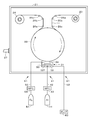
- FIG. 2 is a schematic diagram illustrating an example of the configuration of the film forming apparatus according to the first embodiment of the present technology.
- FIG. 3 is an enlarged cross-sectional view illustrating an example of the configuration of the cathode housing portion illustrated in FIG. 2.
- FIG. 4 is a schematic diagram illustrating an example of a configuration of a film forming apparatus according to a modification of the first embodiment of the present technology.
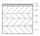
- FIG. 5 is a cross-sectional view showing an example of the configuration of a magnetic recording medium according to the second embodiment of the present technology.
- FIG. 1 is a cross-sectional view showing an example of the configuration of a magnetic recording medium according to the first embodiment of the present technology.
- FIG. 2 is a schematic diagram illustrating an example of the configuration of the film forming apparatus according to the first embodiment of the present technology.
- FIG. 3 is an enlarged cross-section
- FIG. 6 is a schematic diagram illustrating an example of a configuration of a film forming apparatus according to the second embodiment of the present technology.
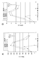
- FIG. 7A is a graph showing the dependency of the vertical coercivity Hc on the amount of O 2 gas introduced.
- FIG. 7B is a graph showing the dependency of the vertical squareness ratio Rs on the amount of O 2 gas introduced.
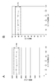
- FIG. 8A is a graph showing the displacement of the vertical coercive force Hc with respect to the sputter deposition length.
- FIG. 8B is a graph showing the displacement of the vertical squareness ratio Rs with respect to the sputter deposition length.
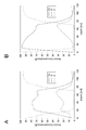
- FIG. 9A is a graph showing the depth profile (depth analysis) of the Co—CoO layer of Example 1-1.
- FIG. 9B is a graph showing a depth profile (depth analysis) of the Co—CoO layer of Comparative Example 1-2.
- FIG. 10A is a graph showing the displacement of the vertical coercive force Hc with respect to the sputter deposition length.
- FIG. 10B is a graph showing the displacement of the vertical squareness ratio Rs with respect to the sputter deposition length.
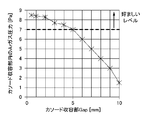
- FIG. 11 is a graph showing the displacement of Ar gas pressure with respect to the gap between the drum and cathode accommodating portion.
- the second gas introduction unit is configured so that the peripheral surface of the drum and the cathode from the upstream or downstream side of the rotation of the drum (that is, the upstream or downstream side of the traveling substrate) or from the width direction side of the peripheral surface of the drum. It is preferable to introduce the second gas between the housing portion.
- the film forming apparatus may include two or more second gas introduction units.
- two second gas introduction portions may be provided, and the second gas may be introduced from both upstream and downstream sides of the drum rotation.
- the second gas may be introduced from both sides in the width direction of the peripheral surface of the drum.
- the magnetic recording medium according to the first embodiment of the present technology includes a long base 11 and a magnetic recording layer 12 provided on the surface of the base 11.
- the magnetic recording medium may further include a protective layer 13 provided on the surface of the magnetic recording layer 12 and a lubricant layer 14 provided on the surface of the protective layer 13 as necessary.
- the magnetic recording medium is a so-called perpendicular magnetic recording medium.
- the variation in the magnetic characteristics of the magnetic recording medium is within ⁇ 10% over a 100 m section in the longitudinal direction of the substrate 11.
- the magnetic characteristic means at least one of the perpendicular coercive force Hc and the perpendicular squareness ratio Rs, preferably both of them.
- the substrate 11 serving as a support is a long non-magnetic substrate having flexibility, and has a surface having a longitudinal direction (MD direction) and a short direction (TD direction).
- a non-magnetic substrate it is preferable to use a long film.
- a flexible polymer resin material used for a normal magnetic recording medium can be used. Specific examples of such a polymer material include polyesters, polyolefins, cellulose derivatives, vinyl resins, polyimides, polyamides, and polycarbonates.
- the magnetic recording layer 12 which is a magnetic layer is a layer obtained by sputtering, that is, a sputtered layer. Whether or not the magnetic recording layer 12 is a sputtered layer can be confirmed, for example, by analyzing whether or not the magnetic recording layer 12 contains an inert gas.
- the magnetic recording layer 12 is a so-called perpendicular magnetization film, and contains Co and Co oxide, which are ferromagnetic materials obtained by an oxidation reaction. These Co and Co oxide are in a mixed state in the magnetic recording layer 12.
- the magnetic recording layer 12 preferably further contains Pt from the viewpoint of improving magnetic characteristics. Specifically, for example, it preferably contains CoPt—O or CoPtCr—O.
- the magnetic recording layer 12 further contains Pt, the magnetic characteristics (for example, the perpendicular coercive force Hc and the perpendicular squareness ratio Rs) can be greatly improved. Therefore, it is possible to improve the output of recording / reproducing signals as a magnetic recording medium and reduce noise.
- the magnetic recording layer 12 containing no Pt is advantageous from the viewpoint of cost.
- the protective layer 13 is for ensuring good running durability and corrosion resistance.
- the protective layer 13 includes, for example, a carbon material or silicon dioxide (SiO 2 ). From the viewpoint of the film strength of the protective layer 13, the protective layer 13 preferably includes a carbon material. Examples of the carbon material include graphite, diamond-like carbon (DLC), diamond, and the like.
- the lubricant layer 14 is for improving the running performance.
- the lubricant layer 14 contains a lubricant.
- a lubricant for example, a silicone-based lubricant, a hydrocarbon-based lubricant, a fluorinated hydrocarbon-based lubricant, or the like can be used.
- the variation in magnetic characteristics is within ⁇ 10% over a section of 100 m in the longitudinal direction of the long substrate 11. Thereby, the magnetic characteristics in the longitudinal direction of the magnetic recording medium can be stabilized. That is, a magnetic recording medium having excellent reliability can be provided.
- the film forming apparatus is a continuous winding type sputtering apparatus, and includes a film forming chamber 21, a drum 22 that is a metal can (rotary body), and a supply.
- a reel 23, a take-up reel 24, a plurality of guide rolls 25a to 25c, 26a to 26c, a cathode accommodating portion 31, gas introducing portions 41 and 51, and an exhaust portion 61 are provided.
- This film forming apparatus is, for example, a DC (direct current) magnetron sputtering system, but the sputtering system is not limited to this system.
- the film forming chamber 21 includes an exhaust pipe 27 and a vacuum pump (not shown) as an exhaust part, and the atmosphere in the film forming chamber 21 is set to a predetermined degree of vacuum by the exhaust part.
- a drum 22, a supply reel 23, and a take-up reel 24 having a rotatable configuration are disposed.
- a plurality of guide rolls 25 a to 25 c for guiding the conveyance of the substrate 11 between the supply reel 23 and the drum 22 are provided, and the drum 22 and the take-up reel 24 are provided.
- a plurality of guide rolls 26a to 26c for guiding the conveyance of the base material 11 between them are provided.
- the substrate 11 unwound from the supply reel 23 is wound around the take-up reel 24 via the guide rolls 25a to 25c, the drum 22, and the guide rolls 26a to 26c.
- the drum 22 has a columnar or cylindrical shape, and the long base 11 is conveyed along the columnar or cylindrical surface of the drum 22.
- the drum 22 is provided with a cooling mechanism (not shown), and is cooled to, for example, about ⁇ 20 ° C. during sputtering.
- a cathode accommodating portion 31 is disposed so as to face the peripheral surface of the drum 22.
- the cathode accommodating portion 31 includes a cathode 32 and an accommodating chamber 33.
- the accommodation chamber 33 accommodates the cathode 32.
- a target 32T can be attached to the cathode 32.
- a target containing Co is used as the target 32T.
- an alloy target containing Co and Pt is used as the target 32T. Examples of such an alloy target include a CoPt alloy target and a CoPtCr alloy target.
- the accommodating chamber 33 includes a wall portion having a configuration capable of heating and cooling.
- the wall portion has an opening 34 on the side facing the peripheral surface of the drum 22. During film formation, the sputtered particles sputtered from the target 32T and released into the gas phase reach the base material 11 that travels along the peripheral surface of the drum 22 through the opening 34, and a thin film is formed. .
- the exhaust part 61 is connected to the wall part of the storage chamber 33.
- the exhaust unit 61 is for evacuating the interior of the storage chamber 33 independently of the film formation chamber 21.
- the exhaust unit 61 includes an exhaust pipe 62 and a vacuum pump 63.
- the storage chamber 33 and the vacuum pump 63 are connected by an exhaust pipe 62.
- a gas introduction part (first gas introduction part) 41 is connected to the wall part of the storage chamber 33.
- the gas introduction part 41 is a gas introduction part for an inert gas for introducing an inert gas (first gas) for promoting plasma discharge into the storage chamber 33.
- the gas introduction part 41 includes a gas introduction pipe 42, a flow rate controller (Mass Flow Controller: MFC) 43, and a gas cylinder 44 as a gas supply part.
- One end of the gas introduction pipe 42 is connected to the storage chamber 33 through the wall portion of the film formation chamber 21.
- the other end of the gas introduction pipe 42 is connected to a gas cylinder 44.
- a flow rate control device 43 is provided in the gas introduction pipe 42.
- the flow control device 43 controls the flow rate of the inert gas introduced from the gas cylinder 44 into the storage chamber 33.
- the flow rate control device 43 is preferably for an inert gas.
- An inert gas is sealed in the gas cylinder 44.
- Ar gas is used as the inert gas.
- a gas introduction part (second gas introduction part) 51 is introduced in the film forming chamber 21, a gas introduction part (second gas introduction part) 51 is introduced.
- the gas introduction part 51 is a gas introduction part for oxidation reactive gas for introducing an oxidation reactive gas (second gas) between the peripheral surface of the drum 22 and the cathode housing part 31.
- the gas introduction part 51 introduces an oxidation reactive gas between the peripheral surface of the drum 22 and the cathode accommodating part 31 from the downstream side of the rotation of the drum 22, that is, the downstream side of the traveling base material 11.
- the gas introduction part 51 includes a gas introduction pipe 52, a flow rate control device 53, and a gas cylinder 54 as a gas supply part.
- One end of the gas introduction pipe 52 is introduced through the wall of the film formation chamber 21 to a position on the downstream side of the rotation of the drum 22 in the periphery of the opening 34 of the storage chamber 33.
- the other end of the gas introduction pipe 52 is connected to a gas cylinder 54.
- a large number of holes for blowing out the oxidation reactive gas are provided at one end of the gas introduction pipe 52 introduced around the opening 34 of the storage chamber 33.
- the gas introduction pipe 52 is provided with a flow rate control device 53.
- the flow control device 53 controls the flow rate of the oxidation reactive gas introduced from the gas cylinder 54 into the storage chamber 33.
- the flow control device 53 is preferably for an oxidation reactive gas.
- the gas cylinder 54 is filled with an oxidation reactive gas.
- the oxidation reactive gas for example, oxygen or a compound containing oxygen is used.
- a gap (gap) is provided between the peripheral surface of the drum 22 and the cathode accommodating portion 31.
- the gap width D G is preferably 0.5 mm or greater and 5.0 mm or less. If the width DG is 0.5 mm, the traveling base material 11 may come into contact with the cathode accommodating portion 31. On the other hand, if the width D G exceeds 5.0 mm, Ar gas discharge diffuses from the cathode container 31 to the outside there is a fear that becomes unstable.
- the film forming apparatus having the above-described configuration includes a drum 22 having a circumferential surface, a cathode housing portion 31 provided to face the circumferential surface of the drum 22, and a gas introduction for introducing an inert gas into the cathode housing portion 31. And a gas introduction part 51 for introducing an oxidation reactive gas between the peripheral surface of the drum 22 and the cathode housing part 31.
- the gas introduction unit 41 introduces an inert gas for promoting plasma discharge into the accommodation chamber 33 into the cathode accommodation unit 31.
- the gas introduction part 51 introduces an oxidation reactive gas between the peripheral surface of the drum 22 and the opening part 34 of the cathode accommodating part 31.
- the concentration of the oxidation reactive gas between the peripheral surface of the drum 22 and the sputtering surface of the target 32T is lower on the sputtering surface side of the target 32T than on the peripheral surface side of the drum 22, so The density can be made higher on the sputter surface side of the target 32T than on the peripheral surface side of the drum 22. For this reason, the oxidation of the sputtering surface of the target 32T by the oxidation reactive gas can be suppressed. Therefore, the characteristics of the thin film continuously formed on the traveling substrate 11 can be stably maintained for a long time.
- the base material 11 having a long shape is unwound from the supply reel 23 and is taken up by the take-up reel 24 while traveling along the peripheral surface of the drum 22.
- the magnetic recording layer 12 can be continuously formed. Therefore, the magnetic recording layer 12 can be continuously formed by the Roll to Roll method.
- the film forming chamber 21 and the accommodating chamber 33 are evacuated to a predetermined degree of vacuum. More specifically, after the inside of the film forming chamber 21 is evacuated and the inside of the film forming chamber 21 reaches a predetermined degree of vacuum, the inside of the housing chamber 33 is evacuated, and the inside of the housing chamber 33 is evacuated. To the degree. Alternatively, the inside of the film forming chamber 21 and the inside of the storage chamber 33 are evacuated simultaneously, and the inside of the storage chamber 33 is set to a predetermined degree of vacuum.
- the ultimate vacuum in the storage chamber 33 is preferably 5.0 ⁇ 10 ⁇ 5 Pa or less. This is because the magnetic recording layer 12 having good characteristics can be formed.
- gas such as O 2 or H 2 O remains on the inner wall surface of the storage chamber 33.
- Heat treatment process Next, it is preferable to heat-treat the wall portion of the storage chamber 33. This is because residual gases such as O 2 and H 2 O can be released from the inner wall surface of the storage chamber 33. From the viewpoint of reducing the residual gas, it is preferable to hold the inner wall surface of the storage chamber 33 at 200 ° C. or higher for 30 minutes or more by heat treatment.
- the recording layer 12 is continuously formed as follows. That is, an inert gas such as Ar gas is introduced into the film forming chamber 21 by the gas introduction part 41, and O 2 is provided between the peripheral surface of the drum 22 and the opening 34 of the cathode accommodating part 31 by the gas introduction part 51. While introducing an oxidation reactive gas such as a gas, the target 32T set on the cathode 32 is sputtered. As a result, the magnetic recording layer 12 is formed on the surface of the base material 11 that travels along the peripheral surface of the drum 22.
- an inert gas such as Ar gas
- O 2 is provided between the peripheral surface of the drum 22 and the opening 34 of the cathode accommodating part 31 by the gas introduction part 51.
- an oxidation reactive gas such as a gas
- the magnetic recording layer 12 containing Co—CoO is formed.
- the target 32T is a target including a CoPt alloy
- the magnetic recording layer 12 including CoPt—O is formed.
- the target 32T is a target including a CoPtCr alloy
- the magnetic recording layer 12 including CoPtCr—O is formed.
- the temperature of the inner wall surface of the storage chamber 33 is preferably maintained at 90 ° C. or lower during the film forming process.
- the substrate 11 wound on the take-up reel 24 is transported from the film forming apparatus to another film forming apparatus, and the protective layer 13 is formed on the surface of the magnetic recording layer 12.
- a method for forming the protective layer 13 for example, a chemical vapor deposition (CVD) method or a physical vapor deposition (PVD) method can be used.
- the base material 11 is conveyed to a coating apparatus, a lubricant or the like is applied to the surface of the protective layer 13, and the lubricant layer 14 is formed.
- a method for applying the lubricant for example, various application methods such as gravure coating and dip coating can be used.
- the magnetic recording medium shown in FIG. 1 is obtained.
- the concentration of the oxidation reactive gas is lower on the sputtering surface side of the target 32T than on the peripheral surface side of the drum 22, and the concentration of the inert gas is reduced. Can be made higher on the sputter surface side of the target 32T than on the peripheral surface side of the drum 22. For this reason, the oxidation of the sputtering surface of the target 32T by the oxidation reactive gas can be suppressed. That is, it is possible to suppress variations in the magnetic characteristics of the magnetic recording medium over a long section in the longitudinal direction of the long substrate 11. For example, the variation in the magnetic characteristics of the magnetic recording medium can be suppressed within ⁇ 10% over a 100 m section.
- the gas introduction part 51 is subjected to an oxidation reaction between the peripheral surface of the drum 22 and the cathode accommodating part 31 from the upstream side of the rotation of the drum 22, that is, the upstream side of the traveling base material 11.
- a sex gas may be introduced.
- one end of the gas introduction pipe 52 is introduced through the wall of the film formation chamber 21 to a position on the upstream side of the rotation of the drum 22 around the opening 34 of the storage chamber 33.
- the film forming apparatus includes two gas introduction portions 51, and the oxidation reactive gas is introduced between the peripheral surface of the drum 22 and the cathode housing portion 31 from both upstream and downstream sides of the rotation of the drum 22. Good.
- the film forming apparatus may be provided with a gas introduction unit that introduces an oxidation reactive gas from four directions or all directions between the peripheral surface of the drum 22 and the cathode housing unit 31.
- the gas introduction pipe has an annular gas blowing portion at one end, and the annular gas blowing portion may be provided so as to surround the opening 34 of the storage chamber 33.
- the film forming apparatus may include a gas introduction unit that introduces a nitrogen reactive gas such as nitrogen gas instead of the gas introduction unit 51 that introduces the oxidation reactive gas.
- a gas introduction unit that introduces a nitrogen reactive gas such as nitrogen gas instead of the gas introduction unit 51 that introduces the oxidation reactive gas.
- the magnetic recording medium according to the second embodiment of the present technology further includes an underlayer 15 and an intermediate layer (seed layer) 16 provided between the base material 11 and the magnetic recording layer 12. It differs from the magnetic recording medium according to the first embodiment in that it is provided.
- the underlayer 15 is provided on the surface of the substrate 11, the intermediate layer 16 is provided on the surface of the underlayer 15, and the magnetic recording layer 12 is provided on the surface of the intermediate layer 16.
- the same parts as those of the magnetic recording medium according to the first embodiment are denoted by the same reference numerals, and description thereof is omitted.
- the underlayer 15 preferably contains an alloy containing Ti and Cr and has an amorphous state. This alloy may further contain O (oxygen).
- the “alloy” means at least one of a solid solution containing Ti and Cr, a eutectic, and an intermetallic compound. “Amorphous state” means that a halo is observed by electron diffraction and the crystal structure cannot be specified.
- the underlayer 15 containing an alloy containing Ti and Cr and having an amorphous state suppresses the influence of O 2 gas and H 2 O adsorbed on the base material 11 and relaxes the unevenness of the surface of the base material 11.
- action which forms a metallic smooth surface on the surface of the base material 11.
- FIG. This action improves the vertical alignment of the intermediate layer 16.
- the state of the underlayer 15 is changed to a crystalline state, the column shape accompanying crystal growth becomes clear, the unevenness of the surface of the substrate 11 is emphasized, and the crystal orientation of the intermediate layer 16 may be deteriorated.
- the alloy contained in the underlayer 15 may further contain elements other than Ti and Cr as additive elements.
- the additive element include one or more elements selected from the group consisting of Nb, Ni, Mo, Al, W, and the like.
- the underlayer 15 is not limited to a single layer structure, and may have a multilayer structure of two or more layers.
- the underlayer 15 includes a first underlayer (upper underlayer) and a second underlayer (lower underlayer).
- the first underlayer is provided on the intermediate layer 16 side
- the second underlayer is provided on the substrate 11 side.
- the first underlayer includes a material having a composition different from that of the second underlayer. Specific examples of this material include NiW or Ta. Note that the first underlayer can be regarded as an intermediate layer, not an underlayer.
- the intermediate layer 16 is intended to make the crystal grains of the magnetic recording layer 12 finer and improve the orientation.
- the intermediate layer 16 is one or more selected from the group consisting of Co, Cu, Ni, Fe, Zr, Pt, Au, Ta, W, Ag, Al, Mn, Cr, Ti, V, Nb, Mo, Ru, and the like.
- the magnetic recording medium having the above-described configuration further includes the underlayer 15 and the intermediate layer 16 provided between the base material 11 and the magnetic recording layer 12, the magnetic recording medium according to the first embodiment. Can further improve the magnetic properties.
- the film forming apparatus according to the second embodiment of the present technology is further provided with cathode accommodating portions 31a and 31b, gas introducing portions 41a and 41b, and exhaust portions 61a and 61b. This is different from the film forming apparatus according to the first embodiment.
- the same parts as those of the film forming apparatus according to the first embodiment are denoted by the same reference numerals, and description thereof is omitted.
- cathode accommodating portions 31 a, 31 b, 31 are disposed so as to face the peripheral surface of the drum 22.
- the cathode accommodating portions 31a, 31b, and 31 are arranged in the order of rotation of the drum 22 with a predetermined interval in this order.
- a gas introduction part (first gas introduction part) 41a and an exhaust part 61a are connected to the accommodation chamber 33 of the cathode accommodation part 31a.
- a target 32Ta can be attached to the cathode 32a.
- the target 32Ta is set for forming the underlayer 15. Width D G of the gap between the circumferential surface and the cathode housing portion 31a of the drum 22 is preferably 0.5mm or more 5.0mm or less.
- a gas introduction part (first gas introduction part) 41b and an exhaust part 61b are connected to the accommodation chamber 33 of the cathode accommodation part 31b.
- a target 32Tb can be attached to the cathode 32b.
- a target for forming the intermediate layer 16 is set as the target 32Tb.
- Width D G of the gap between the circumferential surface and the cathode housing portion 31b of the drum 22 is preferably 0.5mm or more 5.0mm or less.
- the film forming apparatus having the above-described configuration further includes cathode accommodating portions 31 a and 31 b in addition to the cathode accommodating portion 31, and thus a three-layer laminated film composed of the underlayer 15, the intermediate layer 16, the magnetic recording layer 12, and the like. Can be simultaneously formed by one transport of the substrate 11.
- the film forming apparatus includes an exhaust mechanism that exhausts the inside of the cathode housing portion independently.
- exhaust portions 61, 61a, 61b are provided for exhausting the cathode accommodating portions 31, 31a, 31b independently of each other.
- the inside of the film forming chamber 21 and the storage chambers 33 of the cathode storage portions 31, 31a, 31b are evacuated to a predetermined degree of vacuum. More specifically, after the inside of the film forming chamber 21 is evacuated and the inside of the film forming chamber 21 reaches a predetermined degree of vacuum, the inside of the accommodating chamber 33 of each of the cathode accommodating portions 31, 31a, 31b is evacuated. Then, each room is set to a predetermined degree of vacuum.
- the inside of the film forming chamber 21 and the storage chamber 33 of each of the cathode storage portions 31, 31a, 31b are simultaneously evacuated so that the chambers of the cathode storage portions 31, 31a, 31b have a predetermined degree of vacuum.
- the ultimate degree of vacuum in the storage chamber 33 of each of the cathode storage portions 31, 31a, 31b is preferably 5.0 ⁇ 10 ⁇ 5 Pa or less. This is because the underlayer 15, the intermediate layer 16, and the magnetic recording layer 12 having good characteristics can be formed.
- the base material 11 having a long shape is unwound from the supply reel 23, and is wound on the long base material 11 that runs along the peripheral surface of the drum 22 while being wound by the take-up reel 24.
- the base layer 15, the intermediate layer 16, and the magnetic recording layer 12 are continuously formed as follows.
- the target 32Ta set on the cathode 32a is sputtered while introducing an inert gas such as Ar gas into the accommodating chamber 33 by the gas introducing portion 41a.
- the base layer 15 is formed on the base material 11 that travels along the peripheral surface of the drum 22.
- the target 32Tb set on the cathode 32b is sputtered while running along the peripheral surface of the drum 22 while introducing an inert gas such as Ar gas into the accommodating chamber 33 by the gas introducing portion 41b.
- An intermediate layer 16 is formed on the base layer 15 of the substrate 11 to be formed.
- the magnetic recording layer 12 is formed on the intermediate layer 16 of the base material 11 that travels along the peripheral surface of the drum 22 in the same manner as in the first embodiment.
- the film forming process of the protective layer and the lubricant layer is the same as the method for manufacturing the magnetic recording medium according to the first embodiment.
- the magnetic recording medium has been described with respect to the example in which both the base layer 15 and the intermediate layer 16 are provided between the base material 11 and the magnetic recording layer 12.
- One of the layers 16 may be provided.
- the film forming apparatus may include one of the cathode accommodating portion 31a and the cathode accommodating portion 31b. Further, in the method of manufacturing the magnetic recording medium, after forming one of the underlayer 15 and the intermediate layer 16 on the surface of the substrate 11, the magnetic recording layer 12 is formed on the surface of the layer. You can do it.
- the film forming apparatus includes the three cathode accommodating portions 31, 31a, and 31b has been described.
- the film forming apparatus includes two or four or more cathode accommodating portions. It may be.
- a gas introduction part that introduces a reactive gas may be provided between two or more of the cathode accommodation parts and the peripheral surface of the drum 22.
- Examples 1-1 to 1-4 A magnetic tape was manufactured as follows using the film forming apparatus having the configuration shown in FIGS. First, a Co target was attached to the cathode. Incidentally, the drum circumference - setting the width D G of Gap (gap) between the cathode housing portion to 2.0 mm. Next, the film forming chamber and the cathode accommodating portion were evacuated independently. The ultimate degree of vacuum in the cathode accommodating part was set to 5.0 ⁇ 10 ⁇ 5 Pa or less.
- each of the wall portions of the cathode housing portion was heated, and the temperature of the inner wall surface of the cathode housing portion was maintained at 200 ° C. or higher for 30 minutes or longer.
- the long polymer film is unwound from the supply reel, and on the polymer film that runs along the peripheral surface of the drum while being wound by the take-up reel, a Co—CoO layer is formed as follows. Was deposited. That is, while introducing Ar gas into the cathode receptacle by Ar gas inlet, while O 2 gas is introduced from the downstream side of the rotation of the drum between the drum periphery and the cathode housing part by O 2 gas inlet The Co target attached to the cathode was sputtered.
- Examples 2-1 to 2-5 Using the film forming apparatus having the configuration shown in FIG. 4, O 2 gas was introduced from the downstream side of the drum rotation between the drum and the cathode housing portion via the O 2 gas introduction portion. The amount of O 2 gas introduced was adjusted for each sample as shown in Table 1. Except for this, a long magnetic tape was obtained in the same manner as in Examples 1-1 to 1-4.
- the Ar gas introduction part and the O 2 gas introduction part are both provided at positions that face the back surface of the cathode in the wall part of the cathode accommodating part.
- the same materials as 1-1 to 1-4 were prepared.
- Ar gas and O 2 gas were introduced into the cathode accommodating portion by the Ar gas introducing portion and the O 2 gas introducing portion.
- the amount of O 2 gas introduced was adjusted for each sample as shown in Table 1. Except for this, a long magnetic tape was obtained in the same manner as in Example 1-1.
- Table 1 shows the amounts of O 2 gas introduced and magnetic properties of the magnetic tapes of Reference Example 1-1, Examples 1-1 to 1-4, Examples 2-1 to 2-5, and Comparative Examples 1-1 to 1-4. The evaluation result of a characteristic is shown.
- gas introducing method of Example Method of introducing O 2 gas between the drum and the cathode housing portion
- gas inlet of the comparative example Hc and Rs are greatly improved as compared to “method”.
- Hc of 1300 Oe or more and Rs of 20% or more can be obtained by adjusting the O 2 gas introduction amount.
- the O 2 gas introduction amount is reduced. Even if it adjusts, such Hc and Rs cannot be obtained. This is probably because the formation of an oxide film on the surface of the Co target is suppressed in the gas introduction method of the example as compared with the gas introduction method of the comparative example.
- Example 1-2 Hc and Rs are high immediately after film formation, and variations in Hc and Rs are within ⁇ 10% over a 100 m section in the longitudinal direction of the magnetic tape.
- Comparative Example 1-2 Hc and Rs are low immediately after film formation, and variations in Hc and Rs are not within ⁇ 10% over a 100 m section in the longitudinal direction of the magnetic tape.
- Composition analysis Composition analysis in the depth direction of the magnetic recording layer of the magnetic tapes of Example 1-1 and Comparative Example 1-2 was performed using XPS (X-ray Photoelectron Spectroscopy). The results are shown in FIGS. 9A and 9B.
- the Co—CoO layer of Example 1-1 has a high oxygen concentration in the vicinity of a depth of 20 to 40 nm. This is presumably because, during sputtering of the Co—CoO layer, sputtering was performed while introducing O 2 gas between the peripheral surface of the drum and the cathode housing portion, so that oxygen was appropriately taken into the film.
- the oxygen concentration in the vicinity of the depth of 20 to 40 nm is low, and conversely, the Co concentration is high. This is presumably because oxygen was not successfully taken into the film because sputtering was performed while introducing O 2 gas into the cathode housing portion during the Co-CoO layer sputtering.
- Example 3-1 A long magnetic tape was obtained in the same manner as in Example 1-1 except that a CoPtCr alloy target was attached to the cathode and a Co—CoO layer was formed on the polymer film.
- Example 3-1 in which a CoPtCr—O layer was formed using a CoPtCr target, higher Hc and Rs were obtained than in Example 1-1 in which a Co—CoO layer was formed using a Co target. .
- Hc and Rs are as high as about 3000 Oe and about 80% at the stage immediately after film formation, respectively, and variations in Hc and Rs are within ⁇ 10% over a 100 m section in the longitudinal direction of the magnetic tape. is there.
- Ar gas pressure in cathode housing The Ar gas pressure in the cathode housing portion of the prepared film forming apparatuses of Examples 4-1 to 4-11 was measured as follows. First, the film formation chamber of the prepared film formation apparatus and the inside of the cathode housing were evacuated independently. The ultimate degree of vacuum in the cathode accommodating part was set to 5.0 ⁇ 10 ⁇ 5 Pa or less. Next, Ar gas in the cathode accommodating portion was introduced by the Ar gas introducing portion, and the Ar gas pressure in the cathode accommodating portion was measured. The result is shown in FIG.
- the Ar gas pressure in the cathode accommodating part can be set to 7.0 Pa or more. It should be noted that particularly excellent magnetic properties can be obtained when the Ar gas pressure in the cathode housing portion is 7.0 Pa or more.
- the present technology can also employ the following configurations.
- a film forming apparatus comprising: a second gas introduction unit configured to introduce a second gas between the peripheral surface and the cathode housing unit.
- the first gas introduction part is a gas introduction part for an inert gas
- the second gas introduction part introduces the second gas between the peripheral surface and the cathode accommodating part from the upstream or downstream side of the rotation of the drum.
- a film forming apparatus according to claim 1. The film-forming apparatus in any one of (1) to (4) whose gap between the said surrounding surface and the said cathode accommodating part is 0.5 mm or more and 5.0 mm or less.
- the said cathode accommodating part is a film-forming apparatus in any one of (1) to (5) provided with the wall part which has a structure which can be heated and cooled.
- a method of manufacturing a magnetic recording medium comprising: forming a magnetic layer on a long base material that travels along the peripheral surface of the drum by sputtering. (10) The method for manufacturing a magnetic recording medium according to (9), wherein the target includes Co. (11) The method for manufacturing a magnetic recording medium according to (10), wherein the target further contains Pt. (12) The method for manufacturing a magnetic recording medium according to (9) or (10), wherein the magnetic layer contains Co and Co oxide.
Abstract
Description
1 第1の実施形態
1.1 磁気記録媒体の構成
1.2 成膜装置の構成
1.3 磁気記録媒体の製造方法
1.4 変形例
2 第2の実施形態
2.1 磁気記録媒体の構成
2.2 成膜装置の構成
2.3 磁気記録媒体の製造方法
2.4 変形例
[1.1 磁気記録媒体の構成]
図1に示すように、本技術の第1の実施形態に係る磁気記録媒体は、長尺状の基材11と、基材11の表面に設けられた磁気記録層12とを備える。磁気記録媒体は、必要に応じて、磁気記録層12の表面に設けられた保護層13と、保護層13の表面に設けられた潤滑剤層14とをさらに備えるようにしてもよい。磁気記録媒体は、いわゆる垂直磁気記録媒体である。
支持体となる基材11は、可撓性を有する長尺状の非磁性基材であり、長手方向(MD方向)および短手方向(TD方向)を持つ表面を有している。このような非磁性基材としては、長尺状のフィルムを用いることが好ましい。非磁性基材の材料としては、例えば、通常の磁気記録媒体に用いられる可撓性の高分子樹脂材料を用いることができる。このような高分子材料の具体例としては、ポリエステル類、ポリオレフィン類、セルロース誘導体、ビニル系樹脂、ポリイミド類、ポリアミド類またはポリカーボネートなどが挙げられる。
磁性層である磁気記録層12は、スパッタにより得られた層、すなわちスパッタ層である。磁気記録層12がスパッタ層であるか否かは、例えば磁気記録層12に不活性ガスが含有されているか否かを分析することにより確認できる。磁気記録層12は、いわゆる垂直磁化膜であり、酸化反応により得られる強磁性体であるCoとCo酸化物とを含んでいる。これらのCoとCo酸化物とは、磁気記録層12中において混在した状態にある。磁気記録層12は、磁気特性向上の観点から、Ptをさらに含んでいることが好ましい。具体的には例えば、CoPt-OまたはCoPtCr-Oを含んでいることが好ましい。磁気記録層12がPtをさらに含むことで、磁気特性(例えば、垂直保磁力Hcおよび垂直角型比Rs)を大きく向上させることができる。したがって、磁気記録媒体としての記録再生信号の出力向上、およびノイズ低減をはかることが可能となる。但し、コストの観点では、Ptを含んでいない磁気記録層12が有利である。
保護層13は、良好な走行耐久性および耐食性を確保するためのものである。保護層13は、例えば、炭素材料または二酸化ケイ素(SiO2)を含み、保護層13の膜強度の観点からすると、炭素材料を含んでいることが好ましい。炭素材料としては、例えば、グラファイト、ダイヤモンド状炭素(Diamond-Like Carbon:DLC)またはダイヤモンドなどが挙げられる。
潤滑剤層14は、走行性を良好にするためのものである。潤滑剤層14は、潤滑剤を含んでいる。潤滑剤としては、例えば、シリコーン系潤滑剤、炭化水素系潤滑剤またはフッ素化炭化水素系潤滑剤などを用いることができる。
上述の構成を有する磁気記録媒体では、磁気特性のばらつきが、長尺状の基材11の長手方向に100mの区画にわたって±10%以内である。これにより、磁気記録媒体の長手方向の磁気特性を安定させることができる。すなわち、優れた信頼性を有する磁気記録媒体を提供できる。
図2に示すように、本技術の第1の実施形態に係る成膜装置は、連続巻取式スパッタ装置であり、成膜室21と、金属キャン(回転体)であるドラム22と、供給リール23と、巻き取りリール24と、複数のガイドロール25a~25c、26a~26cと、カソード収容部31と、ガス導入部41、51と、排気部61とを備える。この成膜装置は、例えばDC(直流)マグネトロンスパッタリング方式の装置であるが、スパッタリング方式はこの方式に限定されるものではない。
上述の構成を有する成膜装置は、周面を有するドラム22と、ドラム22の周面に対向して設けられたカソード収容部31と、カソード収容部31内に不活性ガスを導入するガス導入部41と、ドラム22の周面とカソード収容部31との間に酸化反応性ガスを導入するガス導入部51とを備える。製膜時には、ガス導入部41がカソード収容部31内にプラズマ放電促進用の不活性ガスを収容室33内に導入する。また、ガス導入部51がドラム22の周面とカソード収容部31の開口部34との間に酸化反応性のガスを導入する。これにより、ドラム22の周面とターゲット32Tのスパッタ面との間において、酸化反応性ガスの濃度をドラム22の周面側に比してターゲット32Tのスパッタ面側で低くし、不活性ガスの濃度をドラム22の周面側に比してターゲット32Tのスパッタ面側で高くできる。このため、酸化反応性ガスによるターゲット32Tのスパッタ面の酸化を抑制できる。したがって、走行する基材11に連続成膜される薄膜の特性を、長時間に渡って安定に保持することができる。
以下、図2を参照して、本技術の第1の実施形態に係る磁気記録媒体の製造方法の一例について説明する。
まず、成膜室21内および収容室33内を真空排気して、所定の真空度にする。より具体的には、成膜室21内を真空引きして、成膜室21内が所定の真空度に到達した後、収容室33内を真空引きして、収容室33内を所定の真空度にする。もしくは、成膜室21内および収容室33内を同時に真空排気して、収容室33内を所定の真空度にする。収容室33の到達真空度は、5.0×10⁻⁵Pa以下であることが好ましい。良好な特性を有する磁気記録層12を成膜できるからである。上述のように収容室33内を真空引きした状態では、一般的に収容室33の内壁面にO2やH2Oなどのガスが残留している。
次に、収容室33の壁部を加熱処理することが好ましい。これにより、収容室33の内壁面からのO2やH2Oなどの残留ガスを放出できるからである。残留ガスの低減の観点からすると、加熱処理により、収容室33の内壁面を200℃以上に、30分以上保持することが好ましい。
次に、長尺状を有する基材11を供給リール23から巻き出すとともに、巻き取りリール24により巻取りながら、ドラム22の周面に沿って走行する長尺状の基材11上に、磁気記録層12を以下のようにして連続成膜する。すなわち、ガス導入部41により成膜室21内にArガスなどの不活性ガスを導入するとともに、ガス導入部51によりドラム22の周面とカソード収容部31の開口部34との間にO2ガスなどの酸化反応性ガスを導入しながら、カソード32にセットされたターゲット32Tをスパッタする。これにより、ドラム22の周面に沿いながら走行する基材11の表面に磁気記録層12が成膜される。
次に、例えば巻き取りリール24に巻き取った基材11を成膜装置から他の成膜装置に搬送して、磁気記録層12の表面に保護層13を成膜する。保護層13の成膜方法としては、例えば化学気相成長(Chemical Vapor Deposition:CVD)法または物理蒸着(physical vapor deposition:PVD)法を用いることができる。
次に、例えば基材11を塗布装置に搬送し、潤滑剤などを保護層13の表面に塗布し、潤滑剤層14を成膜する。潤滑剤の塗布方法はとしては、例えば、グラビアコーティング、ディップコーティングなどの各種塗布方法を用いることができる。以上により、図1に示した磁気記録媒体が得られる。
上述の工程を有する磁気記録媒体の製造方法では、ドラム22の周面に対向するカソード収容部31内に不活性ガスを導入するとともに、ドラム22の周面とカソード収容部31との間に酸化反応性ガスを導入しながら、カソード収容部31内に収容されたターゲット32Tをスパッタする。これにより、ドラム22の周面に沿って走行する長尺状の基材11上に磁気記録層12が形成される。したがって、ドラム22の周面とターゲット32Tのスパッタ面との間において、酸化反応性ガスの濃度をドラム22の周面側に比してターゲット32Tのスパッタ面側で低くし、不活性ガスの濃度をドラム22の周面側に比してターゲット32Tのスパッタ面側で高くできる。このため、酸化反応性ガスによるターゲット32Tのスパッタ面の酸化を抑制できる。すなわち、長尺状の基材11の長手方向に長区間に渡って、磁気記録媒体の磁気特性のばらつきを抑えることができる。例えば、100mの区画にわたって、磁気記録媒体の磁気特性のばらつきを±10%以内に抑えることができる。
図4に示すように、ガス導入部51は、ドラム22の回転の上流の側、すなわち走行する基材11の上流の側から、ドラム22の周面とカソード収容部31との間に酸化反応性ガスを導入するようにしてもよい。この場合、ガス導入管52の一端は、成膜室21の壁部を介して、収容室33の開口部34の周囲うちドラム22の回転の上流側となる位置に導入されている。
[2.1 磁気記録媒体の構成]
図5に示すように、本技術の第2の実施形態に係る磁気記録媒体は、基材11と磁気記録層12との間に設けられた下地層15および中間層(シード層)16をさらに備える点において、第1の実施形態に係る磁気記録媒体とは異なっている。下地層15が基材11の表面に設けられ、中間層16が下地層15の表面に設けられ、磁気記録層12が中間層16の表面に設けられている。第2の実施形態に係る磁気記録媒体において、第1の実施形態に係る磁気記録媒体と同様の箇所には同一の符号を付して説明を省略する。
下地層15は、TiおよびCrを含む合金を含み、アモルファス状態を有していることが好ましい。この合金には、O(酸素)がさらに含まれていてもよい。ここで、「合金」とは、TiおよびCrを含む固溶体、共晶体、および金属間化合物などの少なくとも一種を意味する。「アモルファス状態」とは、電子線回折法により、ハローが観測され、結晶構造を特定できないことを意味する。
中間層16は、磁気記録層12の結晶粒子の微細化と配向性向上を目的とするものである。中間層16は、Co、Cu、Ni、Fe、Zr、Pt、Au、Ta、W、Ag、Al、Mn、Cr、Ti、V、Nb、MoおよびRuなどからなる群より選ばれる1種以上の金属材料を含んでいる。これらの任意の2種類以上を組み合わせた合金、またはこれらの金属材料と酸素や窒素との化合物、酸化ケイ素、窒化ケイ素、ITO(indium tin oxide)、In2O3、ZrO等の化合物、カーボン、ダイヤモンドライクカーボンなどを含んでいてもよい。合金としては、例えばNiWなどのNi合金が挙げられる。
上述の構成を有する磁気記録媒体は、基材11と磁気記録層12との間に設けられた下地層15および中間層16をさらに備えているので、第1の実施形態に係る磁気記録媒体よりも更に磁気特性を改善することができる。
図6に示すように、本技術の第2の実施形態に係る成膜装置は、カソード収容部31a、31bと、ガス導入部41a、41bと、排気部61a、61bとをさらに備える点において、第1の実施形態に係る成膜装置とは異なっている。第2の実施形態に係る成膜装置において、第1の実施形態に係る成膜装置と同様の箇所には同一の符号を付して説明を省略する。
上述の構成を有する成膜装置は、カソード収容部31に加えてカソード収容部31a、31bをさらに備えるので、下地層15、中間層16および磁気記録層12などにより構成される3層の積層膜を、基材11の1回の搬送で同時に成膜することができる。
以下、図6を参照して、本技術の第2の実施形態に係る磁気記録媒体の製造方法の一例について説明する。
まず、成膜室21内およびカソード収容部31、31a、31bそれぞれの収容室33内を真空排気して、所定の真空度にする。より具体的には、成膜室21内を真空引きして、成膜室21内が所定の真空度に到達した後、カソード収容部31、31a、31bそれぞれの収容室33内を真空引きして、それぞれの室内を所定の真空度にする。もしくは、成膜室21内およびカソード収容部31、31a、31bそれぞれの収容室33内を同時に真空排気して、カソード収容部31、31a、31bそれぞれの室内を所定の真空度にする。カソード収容部31、31a、31bそれぞれの収容室33の到達真空度は、5.0×10⁻⁵Pa以下であることが好ましい。良好な特性を有する下地層15、中間層16および磁気記録層12を成膜できるからである。
次に、カソード収容部31、31a、31bそれぞれの収容室33の壁部を加熱処理することが好ましい。
次に、長尺状を有する基材11を供給リール23から巻き出すとともに、巻き取りリール24により巻取りながら、ドラム22の周面に沿って走行する長尺状の基材11上に、下地層15、中間層16および磁気記録層12を以下のようにして連続成膜する。
保護層および潤滑剤層の成膜工程は、第1の実施形態に係る磁気記録媒体の製造方法と同様である。
上述の工程を有する磁気媒体の製造方法では、長尺状の基材11の長手方向に長区間に渡って磁気特性のばらつきを抑えつつ、下地層15、中間層16および磁気記録層12を備える磁気記録媒体を作製することができる。
上述の第2の実施形態では、磁気記録媒体が、基材11と磁気記録層12との間に下地層15および中間層16の両方が設けられた例について説明したが、下地層15および中間層16のうちの一方を備えるようにしてもよい。この場合、成膜装置は、カソード収容部31aおよびカソード収容部31bのうちの一方を備えるようにすればよい。また、磁気記録媒体の製造方法は、基材11の表面に下地層15および中間層16のうちの一方の層を成膜したのちに、その層の表面に磁気記録層12を成膜するようにすればよい。
i O2ガス導入位置と磁気特性との関係
ii CoPtCr-O記録層の磁気特性
iii ドラム-カソード収容部間のギャップとガス圧力との関係
(実施例1-1~1-4)
図2、図3に示した構成を有する成膜装置を用いて、以下のようにして磁気テープを作製した。まず、カソードにCoターゲットを取り付けた。なお、ドラム周面-カソード収容部間のギャプ(隙間)の幅DGを2.0mmに設定した。次に、成膜室内およびカソード収容部内を独立に真空引きした。カソード収容部内の到達真空度は、5.0×10⁻⁵Pa以下とした。
O2ガス導入部によりO2ガスを導入せずにCoターゲットをスパッタして、ドラムの周面に沿って走行する長尺状の高分子フィルム上にCo層を成膜したこと以外は、実施例1-1と同様にして長尺状の磁気テープを得た。
図4に示した構成を有する成膜装置を用いて、O2ガス導入部を介してドラムとカソード収容部との間に、ドラムの回転の下流の側からO2ガスを導入した。また、O2ガスの導入量を表1に示すようにサンプル毎に調整した。これ以外のことは実施例1-1~1-4と同様にして、長尺状の磁気テープを得た。
成膜装置として、Arガス導入部およびO2ガス導入部が共に、カソード収容部の壁部うちカソードの裏面に対向する位置に設けられている以外のことは、参考例1-1、実施例1-1~1-4と同様のものを準備した。この成膜装置を用いて、Arガス導入部、O2ガス導入部によりカソード収容部内にArガス、O2ガスを導入した。また、O2ガスの導入量を表1に示すようにサンプル毎に調整した。これ以外のことは実施例1-1と同様にして、長尺状の磁気テープを得た。
O2ガス導入部によりO2ガスを導入せずにCoターゲットをスパッタして、ドラムの周面に沿って走行する長尺状の高分子フィルム上にCo層を成膜したこと以外は、比較例1-1と同様にして長尺状の磁気テープを得た。
上述のようにして得られた磁気テープについて、以下の評価を行った。
参考例1-1、実施例1-1~1-4、実施例2-1~2-5、比較例1-1~1-4の磁気テープの成膜開始直後における垂直保磁力Hcおよび垂直角型比Rsを振動試料磁力計(Vibrating Sample Magnetometer:VSM)を用いて測定した。その結果を表1、図7A、図7Bに示す。

実施例1-1、比較例1-2の磁気テープの成膜開始直後から所定の成膜長毎の垂直保磁力Hcおよび垂直角型比Rsを、VSMを用いて測定した。その結果を図8A、図8Bに示す。なお、比較例1-2では、成膜直後の段階で磁気特性が悪いため、成膜直後および成膜長10mの磁気特性のみを示す。但し、比較例1-2では、成膜長の増加に伴って、磁気特性がさらに低下する傾向が見えられた。
実施例1-1、比較例1-2の磁気テープの磁気記録層の深さ方向の組成分析をXPS(X-ray Photoelectron Spectroscopy)を用いて行った。その結果を図9A、図9Bに示す。
(実施例3-1)
カソードにCoPtCr合金ターゲットを取り付け、高分子フィルム上にCo-CoO層を成膜したこと以外は実施例1-1と同様にして、長尺状の磁気テープを得た。
実施例3-1の磁気テープの成膜開始直後から所定の成膜長毎の垂直保磁力Hcおよび垂直角型比Rsを、VSMを用いて測定した。その結果を図10A、図10Bに示す。
(実施例4-1~4-11)
図2に示した構成を有するとともに、ドラム-カソード収容部間のギャプの幅DGを0.5mm~10mmの範囲で調整した成膜装置を準備した。
準備した実施例4-1~4-11の成膜装置のカソード収容部のArガス圧力を以下のようにして測定した。まず、準備した成膜装置の成膜室内およびカソード収容部内を独立に真空引きした。カソード収容部内の到達真空度は、5.0×10⁻⁵Pa以下とした。次に、Arガス導入部によりカソード収容部のArガスを導入し、カソード収容部のArガス圧力を測定した。その結果を図11に示す。
(1)
周面を有するドラムと、
上記周面に対向して設けられたカソード収容部と、
上記カソード収容部内に第1のガスを導入する第1のガス導入部と、
上記周面と上記カソード収容部との間に第2のガスを導入する第2のガス導入部と
を備える成膜装置。
(2)
上記第1のガス導入部は、不活性ガス用のガス導入部であり、
上記第2のガス導入部は、酸化反応性ガス用のガス導入部である(1)に記載の成膜装置。
(3)
上記カソード収容部内を排気する排気部をさらに備える(1)または(2)に記載の成膜装置。
(4)
上記第2のガス導入部は、上記ドラムの回転の上流または下流の側から、上記周面と上記カソード収容部との間に上記第2のガスを導入する(1)から(3)のいずれかに記載の成膜装置。
(5)
上記周面と上記カソード収容部との間のギャップは、0.5mm以上5.0mm以下である(1)から(4)のいずれかに記載の成膜装置。
(6)
上記カソード収容部は、加熱冷却可能な構成を有する壁部を備える(1)から(5)のいずれかに記載の成膜装置。
(7)
周面を有するドラムと、
上記周面に対向して設けられた複数のカソード収容部と、
上記複数のカソード収容部内に第1のガスを導入する第1のガス導入部と、
上記周面と上記複数のカソード収容部のうちの少なくとも一つとの間に第2のガスを導入する第2のガス導入部と
を備える成膜装置。
(8)
上記複数のカソード収容部内を独立に排気する排気部をさらに備える(7)に記載の成膜装置。
(9)
ドラムの周面に対向するカソード収容部内に不活性ガスを導入するとともに、上記周面と上記カソード収容部との間に酸化反応性ガスを導入しながら、上記カソード収容部内に収容されたターゲットをスパッタすることにより、上記ドラムの周面に沿って走行する長尺状の基材上に磁性層を形成すること
を含む磁気記録媒体の製造方法。
(10)
上記ターゲットは、Coを含んでいる(9)に記載の磁気記録媒体の製造方法。
(11)
上記ターゲットは、Ptをさらに含んでいる(10)に記載の磁気記録媒体の製造方法。
(12)
上記磁性層は、CoとCo酸化物とを含んでいる(9)または(10)に記載の磁気記録媒体の製造方法。
(13)
磁気特性のばらつきが、上記基材の長手方向に100mの区画にわたって±10%以内である(9)から(12)のいずれかに記載の磁気記録媒体の製造方法。
(14)
上記スパッタ前に、上記カソード収容部を真空引きすることをさらに含み、
上記真空引きによる上記カソード収容部内の到達真空度は、5.0×10⁻⁵Pa以下である(9)から(13)のいずれかに記載の磁気記録媒体の製造方法。
(15)
上記スパッタ前に、上記カソード収容部を加熱することをさらに含んでいる(9)から(14)のいずれかに記載の磁気記録媒体の製造方法。
(16)
上記スパッタ時に、上記カソード収容部を冷却することをさらに含んでいる(9)から(15)のいずれかに記載の磁気記録媒体の製造方法。
(17)
長尺状の可撓性基材と、
スパッタにより得られた、CoとCo酸化物とを含む磁性層と
を備え、
磁気特性のばらつきが、上記基材の長手方向に100mの区画にわたって±10%以内である磁気記録媒体。
12 磁気記録層
13 保護層
14 潤滑剤層
15 下地層
16 中間層
21 成膜室
22 ドラム
31、31a、31b カソード収容部
32、32a、32b カソード
32T、32Ta、32Tb ターゲット
41、41a、41b、51 ガス導入部
61、61a、61b 排気部
Claims (17)
- 周面を有するドラムと、
上記周面に対向して設けられたカソード収容部と、
上記カソード収容部内に第1のガスを導入する第1のガス導入部と、
上記周面と上記カソード収容部との間に第2のガスを導入する第2のガス導入部と
を備える成膜装置。 - 上記第1のガス導入部は、不活性ガス用のガス導入部であり、
上記第2のガス導入部は、酸化反応性ガス用のガス導入部である請求項1に記載の成膜装置。 - 上記カソード収容部内を排気する排気部をさらに備える請求項1に記載の成膜装置。
- 上記第2のガス導入部は、上記ドラムの回転の上流または下流の側から、上記周面と上記カソード収容部との間に上記第2のガスを導入する請求項1に記載の成膜装置。
- 上記周面と上記カソード収容部との間のギャップは、0.5mm以上5.0mm以下である請求項1に記載の成膜装置。
- 上記カソード収容部は、加熱冷却可能な構成を有する壁部を備える請求項1に記載の成膜装置。
- 周面を有するドラムと、
上記周面に対向して設けられた複数のカソード収容部と、
上記複数のカソード収容部内に第1のガスを導入する第1のガス導入部と、
上記周面と上記複数のカソード収容部のうちの少なくとも一つとの間に第2のガスを導入する第2のガス導入部と
を備える成膜装置。 - 上記複数のカソード収容部内を独立に排気する排気部をさらに備える請求項7に記載の成膜装置。
- ドラムの周面に対向するカソード収容部内に不活性ガスを導入するとともに、上記周面と上記カソード収容部との間に酸化反応性ガスを導入しながら、上記カソード収容部内に収容されたターゲットをスパッタすることにより、上記ドラムの周面に沿って走行する長尺状の基材上に磁性層を形成すること
を含む磁気記録媒体の製造方法。 - 上記ターゲットは、Coを含んでいる請求項9に記載の磁気記録媒体の製造方法。
- 上記ターゲットは、Ptをさらに含んでいる請求項10に記載の磁気記録媒体の製造方法。
- 上記磁性層は、CoとCo酸化物とを含んでいる請求項10に記載の磁気記録媒体の製造方法。
- 磁気特性のばらつきが、上記基材の長手方向に100mの区画にわたって±10%以内である請求項9に記載の磁気記録媒体の製造方法。
- 上記スパッタ前に、上記カソード収容部を真空引きすることをさらに含み、
上記真空引きによる上記カソード収容部内の到達真空度は、5.0×10⁻⁵Pa以下である請求項9に記載の磁気記録媒体の製造方法。 - 上記スパッタ前に、上記カソード収容部を加熱することをさらに含んでいる請求項9に記載の磁気記録媒体の製造方法。
- 上記スパッタ時に、上記カソード収容部を冷却することをさらに含んでいる請求項9に記載の磁気記録媒体の製造方法。
- 長尺状の可撓性基材と、
スパッタにより得られた、CoとCo酸化物とを含む磁性層と
を備え、
磁気特性のばらつきが、上記基材の長手方向に100mの区画にわたって±10%以内である磁気記録媒体。
Priority Applications (2)
| Application Number | Priority Date | Filing Date | Title |
|---|---|---|---|
| JP2016567294A JP6652066B2 (ja) | 2014-12-29 | 2015-11-12 | 磁気記録媒体およびその製造方法、ならびに成膜装置 |
| US15/536,546 US20170345453A1 (en) | 2014-12-29 | 2015-11-12 | Magnetic recording medium, method for manufacturing the same, and film forming device |
Applications Claiming Priority (2)
| Application Number | Priority Date | Filing Date | Title |
|---|---|---|---|
| JP2014267069 | 2014-12-29 | ||
| JP2014-267069 | 2014-12-29 |
Publications (1)
| Publication Number | Publication Date |
|---|---|
| WO2016108257A1 true WO2016108257A1 (ja) | 2016-07-07 |
Family
ID=56284413
Family Applications (1)
| Application Number | Title | Priority Date | Filing Date |
|---|---|---|---|
| PCT/JP2015/005665 WO2016108257A1 (ja) | 2014-12-29 | 2015-11-12 | 磁気記録媒体およびその製造方法、ならびに成膜装置 |
Country Status (3)
| Country | Link |
|---|---|
| US (1) | US20170345453A1 (ja) |
| JP (1) | JP6652066B2 (ja) |
| WO (1) | WO2016108257A1 (ja) |
Families Citing this family (1)
| Publication number | Priority date | Publication date | Assignee | Title |
|---|---|---|---|---|
| US11732345B2 (en) * | 2020-06-04 | 2023-08-22 | Applied Materials, Inc. | Vapor deposition apparatus and method for coating a substrate in a vacuum chamber |
Citations (6)
| Publication number | Priority date | Publication date | Assignee | Title |
|---|---|---|---|---|
| JPS63317670A (ja) * | 1987-06-18 | 1988-12-26 | Fuji Electric Co Ltd | 酸化物薄膜の製造方法 |
| JPH08176813A (ja) * | 1994-12-22 | 1996-07-09 | Raiku:Kk | スパッタリング成膜方法及び装置並びにターゲット材料 |
| JP2001152329A (ja) * | 1999-11-24 | 2001-06-05 | Ishikawajima Harima Heavy Ind Co Ltd | 反応性スパッタ方法 |
| JP2004156137A (ja) * | 2002-10-16 | 2004-06-03 | Ulvac Japan Ltd | 薄膜形成装置及び薄膜形成方法 |
| JP2004227621A (ja) * | 2003-01-20 | 2004-08-12 | Fuji Photo Film Co Ltd | 磁気記録媒体の製造方法およびその製造装置 |
| JP2009191308A (ja) * | 2008-02-13 | 2009-08-27 | Toyota Motor Corp | 硬質皮膜および硬質皮膜形成方法、硬質皮膜評価方法 |
Family Cites Families (4)
| Publication number | Priority date | Publication date | Assignee | Title |
|---|---|---|---|---|
| DE3872339T2 (de) * | 1987-10-07 | 1993-01-14 | Emi Plc Thorn | Anlage und verfahren zur herstellung einer schicht auf einem band. |
| WO1992016671A1 (en) * | 1991-03-20 | 1992-10-01 | Canon Kabushiki Kaisha | Method and device for forming film by sputtering process |
| JPH05132770A (ja) * | 1991-11-11 | 1993-05-28 | Canon Inc | スパツタ装置 |
| US6488824B1 (en) * | 1998-11-06 | 2002-12-03 | Raycom Technologies, Inc. | Sputtering apparatus and process for high rate coatings |
-
2015
- 2015-11-12 US US15/536,546 patent/US20170345453A1/en not_active Abandoned
- 2015-11-12 WO PCT/JP2015/005665 patent/WO2016108257A1/ja active Application Filing
- 2015-11-12 JP JP2016567294A patent/JP6652066B2/ja active Active
Patent Citations (6)
| Publication number | Priority date | Publication date | Assignee | Title |
|---|---|---|---|---|
| JPS63317670A (ja) * | 1987-06-18 | 1988-12-26 | Fuji Electric Co Ltd | 酸化物薄膜の製造方法 |
| JPH08176813A (ja) * | 1994-12-22 | 1996-07-09 | Raiku:Kk | スパッタリング成膜方法及び装置並びにターゲット材料 |
| JP2001152329A (ja) * | 1999-11-24 | 2001-06-05 | Ishikawajima Harima Heavy Ind Co Ltd | 反応性スパッタ方法 |
| JP2004156137A (ja) * | 2002-10-16 | 2004-06-03 | Ulvac Japan Ltd | 薄膜形成装置及び薄膜形成方法 |
| JP2004227621A (ja) * | 2003-01-20 | 2004-08-12 | Fuji Photo Film Co Ltd | 磁気記録媒体の製造方法およびその製造装置 |
| JP2009191308A (ja) * | 2008-02-13 | 2009-08-27 | Toyota Motor Corp | 硬質皮膜および硬質皮膜形成方法、硬質皮膜評価方法 |
Also Published As
| Publication number | Publication date |
|---|---|
| JPWO2016108257A1 (ja) | 2017-10-05 |
| JP6652066B2 (ja) | 2020-02-19 |
| US20170345453A1 (en) | 2017-11-30 |
Similar Documents
| Publication | Publication Date | Title |
|---|---|---|
| JP7087389B2 (ja) | 磁気記録媒体 | |
| JP6307879B2 (ja) | 磁気記録媒体およびその製造方法 | |
| JP5192993B2 (ja) | 磁性層の形成方法 | |
| US7354630B2 (en) | Use of oxygen-containing gases in fabrication of granular perpendicular magnetic recording media | |
| JP6652066B2 (ja) | 磁気記録媒体およびその製造方法、ならびに成膜装置 | |
| JP2014203473A (ja) | 磁気記録媒体の製造方法 | |
| JP2010106290A (ja) | 成膜装置および成膜方法、磁気記録媒体、磁気記録再生装置 | |
| US20160060761A1 (en) | Method for manufacturing a carbon-containing protective film | |
| JP2014146401A (ja) | 磁気記録媒体の製造方法及び装置 | |
| JP6118130B2 (ja) | 磁気記録媒体の製造方法及び装置 | |
| JP6485868B2 (ja) | 垂直磁気記録媒体及び磁気記録再生装置 | |
| US11232813B2 (en) | Film-forming apparatus and method for manufacturing magnetic recording medium | |
| JP6485867B2 (ja) | 垂直磁気記録媒体及び磁気記録再生装置 | |
| JP4279644B2 (ja) | 磁気記録媒体の製造方法 | |
| JP2010205323A (ja) | 炭素膜の形成方法及び磁気記録媒体の製造方法 | |
| JP2008033996A (ja) | 磁気記録媒体 | |
| JP2009266266A (ja) | 磁性層の形成方法及び成膜装置と磁気記録再生装置 | |
| JP2004046975A (ja) | 磁気記録媒体の製造方法 | |
| JPH09217174A (ja) | カーボン膜の成膜方法 | |
| JP2004295996A (ja) | 磁気記録媒体の製造方法、磁気記録媒体製造装置および磁気記録媒体 | |
| JPH11238227A (ja) | 磁気記録媒体 | |
| JPH11102521A (ja) | 磁気記録媒体の製造方法 | |
| JP2005149572A (ja) | 磁気記録媒体 | |
| JP2010086570A (ja) | 磁気記録媒体用支持体 | |
| JPH03183020A (ja) | 磁気記録媒体の製造方法 |
Legal Events
| Date | Code | Title | Description |
|---|---|---|---|
| 121 | Ep: the epo has been informed by wipo that ep was designated in this application |
Ref document number: 15875383 Country of ref document: EP Kind code of ref document: A1 |
|
| ENP | Entry into the national phase |
Ref document number: 2016567294 Country of ref document: JP Kind code of ref document: A |
|
| WWE | Wipo information: entry into national phase |
Ref document number: 15536546 Country of ref document: US |
|
| NENP | Non-entry into the national phase |
Ref country code: DE |
|
| 122 | Ep: pct application non-entry in european phase |
Ref document number: 15875383 Country of ref document: EP Kind code of ref document: A1 |