WO2016104687A1 - ディスクブレーキ - Google Patents
ディスクブレーキ Download PDFInfo
- Publication number
- WO2016104687A1 WO2016104687A1 PCT/JP2015/086193 JP2015086193W WO2016104687A1 WO 2016104687 A1 WO2016104687 A1 WO 2016104687A1 JP 2015086193 W JP2015086193 W JP 2015086193W WO 2016104687 A1 WO2016104687 A1 WO 2016104687A1
- Authority
- WO
- WIPO (PCT)
- Prior art keywords
- connector terminal
- terminal
- contact surface
- disc brake
- motor
- Prior art date
- Legal status (The legal status is an assumption and is not a legal conclusion. Google has not performed a legal analysis and makes no representation as to the accuracy of the status listed.)
- Ceased
Links
Images






Classifications
-
- F—MECHANICAL ENGINEERING; LIGHTING; HEATING; WEAPONS; BLASTING
- F16—ENGINEERING ELEMENTS AND UNITS; GENERAL MEASURES FOR PRODUCING AND MAINTAINING EFFECTIVE FUNCTIONING OF MACHINES OR INSTALLATIONS; THERMAL INSULATION IN GENERAL
- F16D—COUPLINGS FOR TRANSMITTING ROTATION; CLUTCHES; BRAKES
- F16D65/00—Parts or details
- F16D65/14—Actuating mechanisms for brakes; Means for initiating operation at a predetermined position
- F16D65/16—Actuating mechanisms for brakes; Means for initiating operation at a predetermined position arranged in or on the brake
- F16D65/18—Actuating mechanisms for brakes; Means for initiating operation at a predetermined position arranged in or on the brake adapted for drawing members together, e.g. for disc brakes
-
- B—PERFORMING OPERATIONS; TRANSPORTING
- B60—VEHICLES IN GENERAL
- B60T—VEHICLE BRAKE CONTROL SYSTEMS OR PARTS THEREOF; BRAKE CONTROL SYSTEMS OR PARTS THEREOF, IN GENERAL; ARRANGEMENT OF BRAKING ELEMENTS ON VEHICLES IN GENERAL; PORTABLE DEVICES FOR PREVENTING UNWANTED MOVEMENT OF VEHICLES; VEHICLE MODIFICATIONS TO FACILITATE COOLING OF BRAKES
- B60T13/00—Transmitting braking action from initiating means to ultimate brake actuator with power assistance or drive; Brake systems incorporating such transmitting means, e.g. air-pressure brake systems
- B60T13/74—Transmitting braking action from initiating means to ultimate brake actuator with power assistance or drive; Brake systems incorporating such transmitting means, e.g. air-pressure brake systems with electrical assistance or drive
- B60T13/741—Transmitting braking action from initiating means to ultimate brake actuator with power assistance or drive; Brake systems incorporating such transmitting means, e.g. air-pressure brake systems with electrical assistance or drive acting on an ultimate actuator
-
- B—PERFORMING OPERATIONS; TRANSPORTING
- B60—VEHICLES IN GENERAL
- B60T—VEHICLE BRAKE CONTROL SYSTEMS OR PARTS THEREOF; BRAKE CONTROL SYSTEMS OR PARTS THEREOF, IN GENERAL; ARRANGEMENT OF BRAKING ELEMENTS ON VEHICLES IN GENERAL; PORTABLE DEVICES FOR PREVENTING UNWANTED MOVEMENT OF VEHICLES; VEHICLE MODIFICATIONS TO FACILITATE COOLING OF BRAKES
- B60T13/00—Transmitting braking action from initiating means to ultimate brake actuator with power assistance or drive; Brake systems incorporating such transmitting means, e.g. air-pressure brake systems
- B60T13/74—Transmitting braking action from initiating means to ultimate brake actuator with power assistance or drive; Brake systems incorporating such transmitting means, e.g. air-pressure brake systems with electrical assistance or drive
- B60T13/746—Transmitting braking action from initiating means to ultimate brake actuator with power assistance or drive; Brake systems incorporating such transmitting means, e.g. air-pressure brake systems with electrical assistance or drive and mechanical transmission of the braking action
-
- F—MECHANICAL ENGINEERING; LIGHTING; HEATING; WEAPONS; BLASTING
- F16—ENGINEERING ELEMENTS AND UNITS; GENERAL MEASURES FOR PRODUCING AND MAINTAINING EFFECTIVE FUNCTIONING OF MACHINES OR INSTALLATIONS; THERMAL INSULATION IN GENERAL
- F16D—COUPLINGS FOR TRANSMITTING ROTATION; CLUTCHES; BRAKES
- F16D55/00—Brakes with substantially-radial braking surfaces pressed together in axial direction, e.g. disc brakes
- F16D55/02—Brakes with substantially-radial braking surfaces pressed together in axial direction, e.g. disc brakes with axially-movable discs or pads pressed against axially-located rotating members
- F16D55/22—Brakes with substantially-radial braking surfaces pressed together in axial direction, e.g. disc brakes with axially-movable discs or pads pressed against axially-located rotating members by clamping an axially-located rotating disc between movable braking members, e.g. movable brake discs or brake pads
- F16D55/224—Brakes with substantially-radial braking surfaces pressed together in axial direction, e.g. disc brakes with axially-movable discs or pads pressed against axially-located rotating members by clamping an axially-located rotating disc between movable braking members, e.g. movable brake discs or brake pads with a common actuating member for the braking members
- F16D55/225—Brakes with substantially-radial braking surfaces pressed together in axial direction, e.g. disc brakes with axially-movable discs or pads pressed against axially-located rotating members by clamping an axially-located rotating disc between movable braking members, e.g. movable brake discs or brake pads with a common actuating member for the braking members the braking members being brake pads
- F16D55/226—Brakes with substantially-radial braking surfaces pressed together in axial direction, e.g. disc brakes with axially-movable discs or pads pressed against axially-located rotating members by clamping an axially-located rotating disc between movable braking members, e.g. movable brake discs or brake pads with a common actuating member for the braking members the braking members being brake pads in which the common actuating member is moved axially, e.g. floating caliper disc brakes
-
- F—MECHANICAL ENGINEERING; LIGHTING; HEATING; WEAPONS; BLASTING
- F16—ENGINEERING ELEMENTS AND UNITS; GENERAL MEASURES FOR PRODUCING AND MAINTAINING EFFECTIVE FUNCTIONING OF MACHINES OR INSTALLATIONS; THERMAL INSULATION IN GENERAL
- F16D—COUPLINGS FOR TRANSMITTING ROTATION; CLUTCHES; BRAKES
- F16D65/00—Parts or details
- F16D65/14—Actuating mechanisms for brakes; Means for initiating operation at a predetermined position
- F16D65/16—Actuating mechanisms for brakes; Means for initiating operation at a predetermined position arranged in or on the brake
- F16D65/18—Actuating mechanisms for brakes; Means for initiating operation at a predetermined position arranged in or on the brake adapted for drawing members together, e.g. for disc brakes
- F16D65/183—Actuating mechanisms for brakes; Means for initiating operation at a predetermined position arranged in or on the brake adapted for drawing members together, e.g. for disc brakes with force-transmitting members arranged side by side acting on a spot type force-applying member
-
- H—ELECTRICITY
- H01—ELECTRIC ELEMENTS
- H01R—ELECTRICALLY-CONDUCTIVE CONNECTIONS; STRUCTURAL ASSOCIATIONS OF A PLURALITY OF MUTUALLY-INSULATED ELECTRICAL CONNECTING ELEMENTS; COUPLING DEVICES; CURRENT COLLECTORS
- H01R13/00—Details of coupling devices of the kinds covered by groups H01R12/70 or H01R24/00 - H01R33/00
- H01R13/02—Contact members
- H01R13/26—Pin or blade contacts for sliding co-operation on one side only
-
- H—ELECTRICITY
- H01—ELECTRIC ELEMENTS
- H01R—ELECTRICALLY-CONDUCTIVE CONNECTIONS; STRUCTURAL ASSOCIATIONS OF A PLURALITY OF MUTUALLY-INSULATED ELECTRICAL CONNECTING ELEMENTS; COUPLING DEVICES; CURRENT COLLECTORS
- H01R4/00—Electrically-conductive connections between two or more conductive members in direct contact, i.e. touching one another; Means for effecting or maintaining such contact; Electrically-conductive connections having two or more spaced connecting locations for conductors and using contact members penetrating insulation
- H01R4/02—Soldered or welded connections
- H01R4/023—Soldered or welded connections between cables or wires and terminals
-
- F—MECHANICAL ENGINEERING; LIGHTING; HEATING; WEAPONS; BLASTING
- F16—ENGINEERING ELEMENTS AND UNITS; GENERAL MEASURES FOR PRODUCING AND MAINTAINING EFFECTIVE FUNCTIONING OF MACHINES OR INSTALLATIONS; THERMAL INSULATION IN GENERAL
- F16D—COUPLINGS FOR TRANSMITTING ROTATION; CLUTCHES; BRAKES
- F16D2121/00—Type of actuator operation force
- F16D2121/18—Electric or magnetic
- F16D2121/24—Electric or magnetic using motors
-
- F—MECHANICAL ENGINEERING; LIGHTING; HEATING; WEAPONS; BLASTING
- F16—ENGINEERING ELEMENTS AND UNITS; GENERAL MEASURES FOR PRODUCING AND MAINTAINING EFFECTIVE FUNCTIONING OF MACHINES OR INSTALLATIONS; THERMAL INSULATION IN GENERAL
- F16D—COUPLINGS FOR TRANSMITTING ROTATION; CLUTCHES; BRAKES
- F16D2125/00—Components of actuators
- F16D2125/18—Mechanical mechanisms
- F16D2125/20—Mechanical mechanisms converting rotation to linear movement or vice versa
- F16D2125/34—Mechanical mechanisms converting rotation to linear movement or vice versa acting in the direction of the axis of rotation
- F16D2125/40—Screw-and-nut
-
- F—MECHANICAL ENGINEERING; LIGHTING; HEATING; WEAPONS; BLASTING
- F16—ENGINEERING ELEMENTS AND UNITS; GENERAL MEASURES FOR PRODUCING AND MAINTAINING EFFECTIVE FUNCTIONING OF MACHINES OR INSTALLATIONS; THERMAL INSULATION IN GENERAL
- F16D—COUPLINGS FOR TRANSMITTING ROTATION; CLUTCHES; BRAKES
- F16D2125/00—Components of actuators
- F16D2125/18—Mechanical mechanisms
- F16D2125/44—Mechanical mechanisms transmitting rotation
- F16D2125/46—Rotating members in mutual engagement
- F16D2125/48—Rotating members in mutual engagement with parallel stationary axes, e.g. spur gears
-
- F—MECHANICAL ENGINEERING; LIGHTING; HEATING; WEAPONS; BLASTING
- F16—ENGINEERING ELEMENTS AND UNITS; GENERAL MEASURES FOR PRODUCING AND MAINTAINING EFFECTIVE FUNCTIONING OF MACHINES OR INSTALLATIONS; THERMAL INSULATION IN GENERAL
- F16D—COUPLINGS FOR TRANSMITTING ROTATION; CLUTCHES; BRAKES
- F16D2125/00—Components of actuators
- F16D2125/18—Mechanical mechanisms
- F16D2125/44—Mechanical mechanisms transmitting rotation
- F16D2125/46—Rotating members in mutual engagement
- F16D2125/50—Rotating members in mutual engagement with parallel non-stationary axes, e.g. planetary gearing
-
- F—MECHANICAL ENGINEERING; LIGHTING; HEATING; WEAPONS; BLASTING
- F16—ENGINEERING ELEMENTS AND UNITS; GENERAL MEASURES FOR PRODUCING AND MAINTAINING EFFECTIVE FUNCTIONING OF MACHINES OR INSTALLATIONS; THERMAL INSULATION IN GENERAL
- F16D—COUPLINGS FOR TRANSMITTING ROTATION; CLUTCHES; BRAKES
- F16D2131/00—Overall arrangement of the actuators or their elements, e.g. modular construction
-
- F—MECHANICAL ENGINEERING; LIGHTING; HEATING; WEAPONS; BLASTING
- F16—ENGINEERING ELEMENTS AND UNITS; GENERAL MEASURES FOR PRODUCING AND MAINTAINING EFFECTIVE FUNCTIONING OF MACHINES OR INSTALLATIONS; THERMAL INSULATION IN GENERAL
- F16D—COUPLINGS FOR TRANSMITTING ROTATION; CLUTCHES; BRAKES
- F16D2250/00—Manufacturing; Assembly
- F16D2250/0084—Assembly or disassembly
Definitions
- the present invention relates to a disc brake used for braking a vehicle.
- Some conventional disc brakes include a parking brake mechanism that is actuated by an electric motor during parking braking (see Patent Document 1).
- connection between the connector terminal and the connection terminal of the motor wiring is an elastic connection, and there is a possibility that the power supply to the electric motor may become unstable due to vibration during traveling of the vehicle. .
- an object of the present invention is to provide a disc brake that can stably supply electric power to an electric motor.
- the present invention provides a motor that moves a piston by operating a rotation / linear motion conversion mechanism housed in a caliper, and is attached to the caliper, houses the motor, and has a lid.
- a connector terminal is fixed, and a wiring for connecting the connector terminal and the motor is provided.
- a joint terminal to be joined to the connector terminal is provided at one end of the wiring, and the joint terminal is one end of the wiring.
- An urging portion that extends and urges the contact surface portion to be in close contact with the connector terminal, and is provided at a position spaced apart from the urging portion of the contact surface portion and contacts the connector terminal when the connector is in contact with the connector terminal.
- a projecting portion disposed such that an end portion of the terminal on the opening portion side and an end portion of the contact surface portion on the opening portion side coincide with each other; an end portion on the opening portion side of the connector terminal; And a welded portion formed across the end portion on the opening side.
- the disc brake of the present invention it is possible to stably supply power to the electric motor.
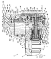
- Sectional drawing which shows the disc brake which concerns on embodiment.
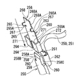
- A) The side view of the state which assembled
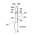
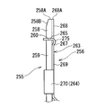
- the side view which shows 3rd Embodiment in the protrusion part of a junction terminal The side view which shows 4th Embodiment in the protrusion part of a junction terminal.
- the disc brake 1 includes a pair of inner brake pads 2 and outer brake pads 3 disposed on both sides in the axial direction with a disc rotor D attached to a rotating portion of the vehicle, and a caliper 4. And are provided.
- the disc brake 1 is configured as a caliper floating type.
- the pair of inner brake pads 2 and outer brake pads 3 and the caliper 4 are supported by a bracket 5 fixed to a non-rotating portion such as a knuckle of the vehicle so as to be movable in the axial direction of the disc rotor D.
- the right side in FIG. 1 will be described as one end side and the left side as the other end side as appropriate.
- the caliper body 6, which is the main body of the caliper 4 includes a cylinder portion 7 disposed on the base end side facing the inner brake pad 2 on the vehicle inner side, and an outer brake pad 3 on the vehicle outer side. And a claw portion 8 that is disposed on the tip side that faces the head.
- the cylinder portion 7 is formed with a bottomed cylinder 15 that is a large-diameter opening portion 9 ⁇ / b> A that is open on the inner brake pad 2 side and is closed on the opposite side by a bottom wall 11 having a hole 10.
- a small-diameter opening 9 ⁇ / b> B that is continuous with the large-diameter opening 9 ⁇ / b> A and has a smaller diameter than the large-diameter opening 9 ⁇ / b> A is formed.
- the cylinder 15 has a piston seal 16 disposed on the inner peripheral surface of the large-diameter opening 9A.
- the piston 18 is formed in a bottomed cup shape including a bottom portion 19 and a cylindrical portion 20.
- the piston 18 is housed in the cylinder 15 so that the bottom 19 faces the inner brake pad 2.
- the piston 18 is housed in the large-diameter opening 9A of the cylinder 15 so as to be movable in the axial direction while being in contact with the piston seal 16.
- a space between the piston 18 and the bottom wall 11 of the cylinder 15 is defined by a piston seal 16 as a hydraulic chamber 21.
- the fluid pressure chamber 21 is supplied with fluid pressure from a fluid pressure source (not shown) such as a master cylinder or a fluid pressure control unit through a port (not shown) provided in the cylinder portion 7.
- a plurality of rotation restricting vertical grooves 22 are formed on the inner peripheral surface of the piston 18 along the circumferential direction.
- a recess 25 is provided on the outer peripheral side of the other end surface of the bottom portion 19 of the piston 18 facing the inner brake pad 2.
- the concave portion 25 is engaged with a convex portion 26 formed on the back surface of the inner brake pad 2.
- a dust boot 27 is interposed between the outer peripheral surface of the piston 18 on the bottom 19 side and the inner peripheral surface of the large-diameter opening 9 ⁇ / b> A of the cylinder 15 to prevent foreign matter from entering the cylinder 15. .
- a housing 30 in which a motor gear assembly 29 is accommodated is attached on the bottom wall 11 side of the cylinder 15 of the caliper body 6.
- An opening 30 ⁇ / b> A is provided at one end of the housing 30.
- a cover 36 (lid member) that is airtightly closed is attached to the opening 30A.
- the opening 30A of the housing 30 is closed by the cover 36 (lid member).
- a seal member 37 is provided between the housing 30 and the cylinder portion 7. The inside of the housing 30 is kept airtight by the seal member 37.
- the housing 30 is integrally formed from a first housing part 31 and a first housing part 31 that accommodates a spur multi-stage reduction mechanism 44 and a planetary gear reduction mechanism 45 described later so as to cover the outer periphery of the bottom wall 11 of the cylinder 15. And a second housing portion 32 that houses the motor 200. As described above, the housing 30 is configured to accommodate the motor 200 arranged in line with the caliper body 6 by the bottomed cylindrical second housing portion 32.
- the first housing portion 31 includes an outer wall portion 31F and a bottom surface portion 31G that surround a housing chamber 31E that houses a later-described spur gear multi-stage reduction mechanism 44 and a planetary gear reduction mechanism 45 together with a cover 36, and a part of the bottom wall 11 of the cylinder 15.
- a connector portion 34 having two connection terminals 33 is integrally provided so as to straddle the first housing portion 31 and the second housing portion 32.
- Each connection terminal 33 is electrically connected to each connector terminal 255 disposed in the first housing portion 31.
- Each connector terminal 255 is disposed in the first housing portion 31 in proximity to the outer wall portion 31F on the connector portion 34 side.
- Each connector terminal 255 extends toward the opening 30 ⁇ / b> A of the housing 30.
- each connection terminal 33 and each connector terminal 255 are each a single metal wire and are molded in the housing 30.
- Each one metal wire serves as a connection terminal 33 whose one end projects into the connector portion 34, and the other end serves as a connector terminal 255 extending from the bottom surface portion 31 ⁇ / b> G of the first housing portion 31 toward the opening 30 ⁇ / b> A. Yes.
- the connector terminal 255 is formed in a plate shape.
- Each connector terminal 255 is configured integrally with a narrow portion 258 located on the opening 30A side and a wide portion 259 provided continuously from the narrow portion 258 to the motor 200 side.
- the narrow part 258 and the wide part 259 are each formed in a substantially rectangular shape when viewed from the front.
- each connector terminal 255 and a joining terminal 256 described later is referred to as the front, and the front view indicates the front of the connector terminal 255.
- the narrow part 258 and the wide part 259 have substantially the same thickness.
- step surfaces 260 are formed between the narrow portion 258 and the wide portion 259, respectively.
- a guide taper surface 258B whose thickness decreases toward the end portion 258A is formed on the surface of the housing 30 on the opening 30A side opposite to the joining terminal 256 side. .
- the surface near the outer wall portion 31F of the connector terminal 255 is a wall side plane 255A
- the opposite side of the wall side plane 255A is a flat plate surface 255B that comes into close contact with a contact surface portion 263 of a joining terminal 256 described later. ing.
- the wall side flat surface 255A is the back surface of the flat plate surface.
- the caliper body 6 has a spur multi-stage reduction mechanism 44 and a planetary gear reduction mechanism 45 that reinforces the driving force of the motor 200, and the piston 18 is propelled and the propelled piston is held in the braking position.
- a rotation / linear motion conversion mechanism 43 is provided.
- the spur multi-stage speed reduction mechanism 44 and the planetary gear speed reduction mechanism 45 as the speed reduction mechanism are accommodated in an accommodation chamber 31 ⁇ / b> E in the first housing portion 31 of the housing 30.
- the spur multi-stage reduction mechanism 44 includes a pinion gear 46, a first reduction gear 47, a non-reduction spur gear 48, and a second reduction gear 49.
- the first reduction gear 47, the non-reduction spur gear 48, and the second reduction gear 49 are metal or resin such as fiber reinforced resin.
- the pinion gear 46 is formed in a cylindrical shape, and has a hole 50 that is press-fitted and fixed to the rotating shaft 201 of the motor 200, and a gear 51 that is formed on the outer periphery.
- the first reduction gear 47 is integrally formed with a large-diameter large gear 53 that meshes with the gear 51 of the pinion gear 46 and a small-diameter small gear 54 that extends from the large gear 53 in the axial direction. .
- the first reduction gear 47 is rotatably supported by a shaft 52 with respect to a support plate 59 and a holder 205 described later.
- One end of the shaft 52 is supported by the support plate 59 close to the cover 36, and the other end is supported by the holder 205.
- the small gear 54 of the first reduction gear 47 meshes with the non-reduction spur gear 48.
- the non-reducing spur gear 48 is rotatably supported with respect to the support plate 59 and the holder 205 by a shaft 55 (see FIG. 2).
- One end of the shaft 55 is supported by the support plate 59 close to the cover 36, and the other end is supported by the holder 205.
- the second reduction gear 49 is integrally formed with a large-diameter large gear 56 that meshes with the non-reducing spur gear 48 and a small-diameter sun gear 57 that extends from the large gear 56 in the axial direction.
- the sun gear 57 is configured as a part of a planetary gear reduction mechanism 45 described later.
- a hole 49A is formed at the center of the second reduction gear 49, and the shaft 58 is inserted therethrough.
- the shaft 58 is press-fitted and fixed to a support plate 59 provided at one end close to the cover 36.
- the second reduction gear 49 is rotatably supported by the shaft 58.
- an annular stopper portion 56 ⁇ / b> A that protrudes toward the planetary gear reduction mechanism 45 is formed on the annular wall portion of the large gear 56 of the second reduction gear 49.
- the planetary gear reduction mechanism 45 includes a sun gear 57 of the second reduction gear 49, a plurality (four in this embodiment) of planetary gears 60, an internal gear 61, and a carrier 62.
- Each planetary gear 60 has a gear 63 meshed with the sun gear 57 of the second reduction gear 49 and a hole 64 through which a pin 65 erected from the carrier 62 is rotatably inserted.
- the planetary gears 60 are arranged at equal intervals on the circumference of the carrier 62.
- An annular plate 66 is disposed on the other end side of each planetary gear 60.
- the carrier 62 is formed in a disk shape, and a polygonal hole 68 is formed at the substantially radial center.
- the outer diameter of the carrier 62 is substantially the same as the outer diameter of the revolution trajectory of each planetary gear 60.
- a plurality of pin holes 69 are formed on the outer peripheral side of the carrier 62 at intervals along the circumferential direction.
- a pin 65 is press-fitted and fixed in each pin hole 69.
- Each pin 65 is rotatably inserted into a hole 64 of each planetary gear 60.
- the carrier 62 and the base nut 75 transmit rotational torque to each other by fitting the polygonal hole 68 of the carrier 62 and the polygonal shaft portion 81 of the base nut 75 of the rotation / linear motion converting mechanism 43 described later. It can be done.
- the internal gear 61 continuously extends radially from one end on the cover 36 side of the internal teeth 71 with which the gear 63 of each planetary gear 60 is engaged, and restricts the movement of each planetary gear 60 in the axial direction. And a cylindrical wall portion 73 extending from the inner teeth 71 toward the bottom wall 11 of the cylinder 15.
- the internal gear 61 is fixed to the housing 30 by inserting the cylindrical wall portion 73 into the annular space between the inner annular wall portion 31B and the outer annular wall portion 31C of the first housing portion 31.
- An annular plate 66 is disposed inside the internal gear 61.
- each planetary gear 60 is arrange
- a plurality of protrusions 74 arranged at intervals in the circumferential direction are provided protruding outward.
- Each protrusion 74 is engaged with each engagement groove 31 ⁇ / b> D provided in the first housing portion 31.
- the internal gear 61 is supported in the first housing portion 31 so as not to rotate, as each projection 74 thereof is inserted and engaged with each engagement groove 31 ⁇ / b> D of the first housing portion 31.
- the internal gear 61 is not movable in the axial direction because the annular stopper portion 56A provided on the large gear 56 of the second reduction gear 49 is disposed on the cover 36 side of the annular wall portion 72. It is supported in the first housing part 31.
- the motor 200 is supported by a holder 205 disposed on the flange portion 202.
- the holder 205 is configured by integrally connecting a motor support portion 206 and a ring-shaped support portion 207.
- the motor support portion 206 is arranged between the first reduction gear 47 and the non-reduction spur gear 48 and the flange portion 202 of the motor 200 to support the motor 200.
- the ring-shaped support portion 207 is disposed around the internal gear 61 of the planetary gear reduction mechanism 45 so as to surround the internal gear 61.
- the motor support portion 206 is formed with a rotation shaft insertion hole 208 through which the pinion gear 46 press-fitted and fixed to the rotation shaft 201 of the motor 200 is inserted.
- Around the rotation shaft insertion hole 208 two terminal insertion holes through which the motor terminals 203 of the motor 200 are inserted are formed.
- a pair of terminal insertion holes is formed on both sides in the radial direction of the rotation shaft insertion hole 208.
- the motor support portion 206 of the holder 205 includes a holder-side first convex portion 211, a holder-side second convex portion 212, and a holder-side first portion on the opposite side of the planetary gear speed reduction mechanism 45 around the rotation shaft insertion hole 208.
- Three convex portions 213 are formed at intervals from each other.
- the holder-side first convex portion 211, the holder-side second convex portion 212, and the holder-side third convex portion 213 are formed in a columnar shape and project toward the cover 36 side.
- Two fastening holes 216 are formed in the motor support portion 206.
- Each mounting bolt 215 is fastened to the fastening hole 216 of the motor support portion 206 via each through hole 202 ⁇ / b> A of the flange portion 202 of the motor 200.
- the motor 200 is supported by the motor support part 206 of the holder 205.
- the ring-shaped support portion 207 is disposed above each protrusion 74 so as to contact the outer peripheral surface of the internal gear 61 of the planetary gear reduction mechanism 45.
- cylindrical support portions 217 and 217 are integrally formed at two positions between the motor support portion 206 and the ring-shaped support portion 207.
- a support plate 59 is disposed on each cylindrical support portion 217, and each mounting bolt 218 is fastened to each cylindrical support portion 217 of the holder 205 via the support plate 59, whereby the support plate 59 is placed on the holder 205. Be supported at intervals.
- a cover-side first cylindrical portion 221, a cover-side second convex portion 222, and a cover-side third convex portion 223 are provided so as to be spaced apart from each other.
- the cover-side first cylindrical portion 221, the cover-side second convex portion 222, and the cover-side third convex portion 223 are a holder-side first convex portion 211, a holder-side second convex portion 212, and a holder-side provided on the holder 205. Each is formed at a position facing the third convex portion 213.
- a rubber 230 which is an elastic member, is interposed between 212 and the holder-side third convex portion 213.
- the rubber 230 is formed by integrating the first cup portion 231, the second cup portion 232, the third cup portion 233, and the opening side end portions of the first cup portion 231, the second cup portion 232, and the third cup portion 233. And a plate-like base portion 234 connected to each other.
- the first cup portion 231 of the rubber 230 is fitted to the holder-side first convex portion 211 of the holder 205
- the second cup portion 232 of the rubber 230 is fitted to the holder-side second convex portion 212 of the holder 205
- the third cup portion 233 of the rubber 230 is fitted to the holder-side third convex portion 213 of the holder 205 so that the rubber 230 is unitized with the holder 205.
- the cover-side first cylindrical portion 221 of the cover 36 is fitted into the first cup portion 231 of the rubber 230
- the cover-side second convex portion 222 of the cover 36 is fitted to the second cup portion 232 of the rubber 230.
- cover 36 is covered so that the cover side third convex portion 223 of the cover 36 contacts the third cup portion 233 of the rubber 230. Harnesses 250 and 251 extending from the motor terminals 203 of the motor 200 are arranged along the base portion 234 of the rubber 230.
- a plurality of types of rubbers 281, 282, and 283 different from the rubber 230 described above are provided in the housing 30.
- a U-shaped support section 280 is formed at the end of the holder 205 on the motor support section 206 side, and a U-shaped rubber section 281 is integrally disposed therein.
- Block-shaped rubbers 282 are respectively disposed between the outer peripheral surface at a position close to each cylindrical support portion 217 and the inner wall surface of the first housing portion 31 in the ring-shaped support portion 207 of the holder 205.
- a cylindrical rubber 283 is disposed between the main body side end portion of the motor 200 and the bottom wall portion of the second housing portion 32.
- the motor gear assembly 29 is configured by assembling the motor 200, the spur multi-stage reduction mechanism 44, the planetary gear reduction mechanism 45, and the rubbers 230, 281, 282, and 283 to the holder 205 and the support plate 59.
- the motor gear assembly 29 is attached to the housing 30 and the cover 36 by rubbers 230, 281, 282, and 283 in a suspended state, that is, a so-called floating state.
- the motor gear assembly 29 is fixed to the housing 30 and the cover 36 via the rubbers 230, 281, 282, and 283 without the holder 205 coming into contact with the housing 30 and the cover 36.
- the motor gear assembly 29 is fixed to the housing 30 and the cover 36 via the rubbers 230, 281, 282, and 283, so that the motor 200, the spur multi-stage reduction mechanism 44, and the planetary gear reduction mechanism 45 are generated.
- the transmission of the vibration to be transmitted to the housing 30 or the cover 36 is suppressed, and the generation of sound accompanying the vibration can be suppressed.
- the spur multi-stage reduction mechanism 44 and the planetary gear reduction mechanism 45 as the reduction mechanism that reinforces the driving force by the motor 200 are employed. You may comprise only the deceleration mechanism 45.
- a speed reducer according to another known technique such as a cycloid speed reduction mechanism or a wave speed reducer may be combined with the planetary gear speed reduction mechanism 45.
- each motor terminal 203 of the motor 200 and each connector terminal 255 provided in the second housing portion 32 are electrically connected by harnesses 250 and 251 which are wirings for connecting them. Connected to. One end of each harness 250 and 251 is provided with a joining terminal 256 connected to the connector terminal 255. The other ends of the harnesses 250 and 251 are connected to the motor terminals 203 of the motor 200.
- the harnesses 250 and 251 in the present embodiment are made of stranded wires of thin metal wires and have flexibility.
- the joining terminal 256 of the first embodiment is formed in a plate shape as a whole except for the fixing portion 262.
- the joining terminal 256 is formed thinner than the connector terminal 255.
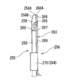
- the junction terminal 256 mainly includes a fixed portion 262, a contact surface portion 263, an urging portion 264, a protruding portion 265, and a welded portion 266.
- Each harness 250 (251) is fixed to the fixing portion 262.
- the fixing part 262 is formed in a cylindrical shape with one end of the harness 250 (251) held inside the fixing part 262.
- the contact surface portion 263 is formed to extend from the fixed portion 262, and is in close contact with the flat plate surface 255B of the connector terminal 255.
- the urging portion 264 is formed to extend from the side surface of the contact surface portion 263 to the wall side plane 255A of the connector terminal 255, and urges the contact surface portion 263 so as to be in close contact with the flat plate portion 255B of the connector terminal 255.
- the protruding portion 265 is formed to extend from a position separated from the urging portion 264, that is, from the position of the side surface of the contact surface portion 263 that is the tip side of the urging portion 264, and comes into contact with the step surface 260 of the connector terminal 255.
- end surface 268 ⁇ / b> A which is the tip of the contact surface portion 263 and the end surface 258 ⁇ / b> A of the connector terminal 255 on the opening 30 ⁇ / b> A side of the housing 30 are arranged so as to coincide with each other.
- the welded portion 266 is formed across the end portion 268A serving as the tip of the contact surface portion 263 and the end portion 258A on the opening 30A side of the housing 30 in the connector terminal 255.
- the contact surface portion 263 is formed in a plate shape, and extends from the fixed portion 262 to the opening 30A side of the housing 30 via a connecting portion 261 that exhibits a crank shape in a side view (see FIG. 5).
- the connecting portion 261 is formed with a connecting portion extending in a direction away from the flat plate surface of the connector terminal as it goes from the contact surface portion 263 to the fixed portion 262.
- the contact surface portion 263 includes a narrow contact surface portion 268 corresponding to the narrow portion 258 of the connector terminal 255 and a wide contact surface portion 269 corresponding to the wide portion 259 of the connector terminal 255.
- the narrow contact surface portion 268 and the wide contact surface portion 269 are each formed in a substantially rectangular shape when viewed from the front.
- the contact surface between the connector terminal 255 and the joining terminal 256 is referred to as the front, and the front view indicates a case where the front of the joining terminal 256 is viewed.
- step portions 267 are formed between the narrow contact surface portion 268 and the wide contact surface portion 269, respectively.
- a biasing portion 264 is provided from the side surface of the wide contact surface portion 269 toward the connector terminal 255 side.
- the urging portion 264 includes a pair of urging portions 264 and 264 extending from both side surfaces 269A of the wide contact surface portion 269.
- the pair of urging portions 264 and 264 are formed at positions on the fixed portion 262 side in the wide contact surface portion 269.
- Each of the urging portions 264 and 264 includes plate-like pressing portions 271 and 271 extending in parallel with the contact surface portion 263 and a plate-like support portion 272 extending from the side surface 269A of the wide contact surface portion 269 in a direction orthogonal to the wide contact surface portion 269.
- the cross section is formed in a substantially L shape.
- the plate-like pressing part 271 is formed in a substantially rectangular shape when viewed from the front.
- the plate-like pressing portions 271 and 271 of each urging portion 264 are arranged so as to be close to each other with a gap between them.
- the plate-like support part 272 is formed in a substantially rectangular shape in a side view.
- the pair of plate-like support portions 272 and 272 are formed so as to sandwich the both side surfaces 259A and 259A of the wide portion 259 of the connector terminal 255, that is, extending with an interval substantially equal to the wide portion 259 of the connector terminal 255. ing. With such an urging portion 264, the contact surface portion 263 comes into close contact with the flat plate surface 255 ⁇ / b> B of the connector terminal 255.
- the protruding portion 265 is formed in a plate shape, and is located on the connector terminal 255 side so as to be orthogonal to the narrow contact surface portion 268 from both side surfaces 268A close to the step portion 267 in the narrow contact surface portion 268 of the joining terminal 256. It is constructed by bending in the direction.
- Each protrusion 265, 265 is formed in a substantially rectangular shape in a side view.
- Each projecting portion 265, 265 extends substantially parallel to the plate-like support portion 272 of each biasing portion 264, 264.
- the protruding length of each protruding portion 265, 265 is set to a length corresponding to the thickness of the connector terminal 255.
- the protrusions 265 and 265 are formed when the wide portion 259 of the connector terminal 255 is inserted between the plate-like pressing portion 271 and the wide contact surface portion 269 of the biasing portion 264 of the joining terminal 256. , 265 on the wide contact surface portion 269 side comes into contact with the stepped surfaces 260, 260 of the connector terminal 255.
- the joining terminals 256 are positioned with respect to the connector terminal 255 by the protrusions 265 and 265 coming into contact with the stepped surfaces 260 and 260 of the connector terminal 255.
- Each of the protrusions 265 and 265 is formed at a position where the inner surfaces 265B and 265B serving as opposing surfaces thereof face the side surfaces 258A and 258A of the narrow portion 258 of the connector terminal 255 with a gap.
- the joining terminal 256 is connected from the narrow portion 258 side of the connector terminal 255 to the wide portion 259 of the connector terminal 255, and each biasing portion 264 of the joining terminal 256. Are inserted so as to be sandwiched between the plate-like pressing portion 271 and the wide contact surface portion 269, and the protruding portions 265 of the joining terminal 256 are brought into contact with the stepped surfaces 260 provided on both side surfaces of the connector terminal 255.
- the connector terminal 255 is positioned between the plate-like pressing portion 271 and the wide contact surface portion 269 of each urging portion 264 of the joining terminal 256 along the guide taper surface 258B provided in the narrow portion 258. Be guided to.
- each biasing portion 264 of the joining terminal 256 biases the wide portion 259 of the connector terminal 255 and each plate-like pressing portion 271 of the joining terminal 256 so as to be in close contact with each other. Further, each biasing portion 264 of the joining terminal 256 positions the joining terminal 256 and the connector terminal 255 in the width direction and the thickness direction. Further, each protrusion 265 of the joining terminal 256 makes the tip of the connector terminal 255 coincide with the tip of the joining terminal 256.
- each protruding portion 265 of the joining terminal 256 positions the joining terminal 256 and the connector terminal 255 in the insertion direction, and the end portion 258A on the opening 30A side of the housing 30 in the narrow portion 258 of the connector terminal 255.
- the end portion 268A on the opening 30A side of the housing 30 in the narrow contact surface portion 268 of the joining terminal 256 are matched.
- the welded portion 266 is formed by welding the end portion 258A on the distal end side of the connector terminal 255 and the end portion 268A on the distal end side of the joining terminal 256 so as to straddle both.
- the welded portion 266 includes the end portion 258A on the opening 30A side of the housing 30 in the narrow portion 258 of the connector terminal 255 and the end portion on the opening portion 30A side of the housing 30 in the narrow contact surface portion 268 of the joining terminal 256.
- the welding part 266 is formed by joining by TIG welding (tungsten inert gas welding).
- the welded portion 266 of the joining terminal 256 is disposed at a position farthest from the fixed portion 262. In this manner, by forming the welded portion 266 across the connector terminal 255 and the joining terminal 256, the connector terminal 255 and the joining terminal 256 can be joined to ensure electrical connection.
- the harnesses 250 and 251 made of thin metal wires are used as the wiring for connecting the motor 200 and the connector terminal 255.
- the wiring has flexibility. If so, a bus bar made of a metal plate may be used.
- the rotation / linear motion conversion mechanism 43 converts the rotational motion from the spur multi-stage speed reduction mechanism 44 and the planetary gear speed reduction mechanism 45, that is, rotation of the motor 200 into motion in a linear direction (hereinafter referred to as linear motion for convenience), and the piston 18.
- a thrust is applied to the piston 18 to hold the piston 18 in the braking position.
- the rotation / linear motion converting mechanism 43 includes a base nut 75 that is a rotation transmitting member that is rotatably supported by the rotational motion transmitted from the spur multi-stage speed reduction mechanism 44 and the planetary gear speed reduction mechanism 45, and a female screw of the base nut 75.
- a push rod 102 that is a shaft member that is screw-fitted to the portion 97 and is rotatably supported by the rotation of the base nut 75 and a shaft member, and the push rod 102 that is screw-fitted to the push rod 102 And a ball and ramp mechanism 127 that applies thrust in the axial direction to the piston 18 by the rotation of.
- the rotation / linear motion conversion mechanism 43 is accommodated between the cylinder 15 and the piston 18 of the caliper body 6.
- the base nut 75 includes a cylindrical portion 76 and a nut portion 77 provided integrally with the other end of the cylindrical portion 76.
- a washer 80 is disposed in contact with the bottom wall 11 of the cylinder 15.
- the cylindrical portion 76 of the base nut 75 is inserted into each of the insertion hole 80 ⁇ / b> A of the washer 80 and the hole portion 10 provided in the bottom wall 11 of the cylinder 15.
- a polygonal shaft portion 81 is integrally connected to the tip of the cylindrical portion 76.
- the polygonal shaft portion 81 is inserted through the attachment opening 31 ⁇ / b> A of the first housing portion 31 and is fitted into the polygonal hole 68 of the carrier 62.
- the nut portion 77 of the base nut 75 is formed in a bottomed cylindrical shape.
- the nut portion 77 includes a circular wall portion 82 and a cylindrical portion 83 that protrudes integrally from the other end surface of the circular wall portion 82.
- the outer peripheral surface of the circular wall portion 82 is close to the inner wall surface of the small diameter opening 9 ⁇ / b> B of the cylinder 15.
- a small-diameter circular wall 84 protrudes from the radial center of one end face of the circular wall 82.
- a cylindrical portion 76 projects from one end surface of the small-diameter circular wall portion 84 toward one end side.
- the outer diameter of the cylindrical portion 76 is formed smaller than the outer diameter of the cylindrical portion 83 of the nut portion 77.
- the thrust bearing 87 is disposed between the washer 80 and the circular wall portion 82 around the small-diameter circular wall portion 84 provided on the nut portion 77 of the base nut 75.
- the base nut 75 is rotatably supported by the bottom wall 11 of the cylinder 15 by a thrust bearing 87.
- a seal member 88 and a sleeve 89 are provided between the outer peripheral surface of the cylindrical portion 76 of the base nut 75 and the hole 10 of the bottom wall 11 of the cylinder 15. Thereby, the fluid tightness of the hydraulic chamber 21 is maintained.
- a retaining ring 90 is mounted in an annular groove provided between the cylindrical portion 76 of the base nut 75 and the polygonal shaft portion 81, and movement of the base nut 75 in the axial direction of the cylinder 15 is restricted by the retaining ring 90.
- the cylindrical portion 83 of the nut portion 77 of the base nut 75 includes a large diameter cylindrical portion 91 disposed on one end side and a small diameter cylindrical portion 92 disposed on the other end side.
- One end of the large diameter cylindrical portion 91 is integrally connected to the circular wall portion 82.
- a plurality of through holes 95 extending in the radial direction are formed in the peripheral wall portion of the large diameter cylindrical portion 91.
- a plurality of through holes 95 are formed at intervals in the circumferential direction.
- a female thread portion 97 is formed on the inner peripheral surface of the small diameter cylindrical portion 92 of the nut portion 77.
- a plurality of locking grooves 98 are formed on the other end surface of the peripheral wall portion of the small diameter cylindrical portion 92 at intervals in the circumferential direction. In the present embodiment, four locking grooves 98 are formed.
- the front end portion of the first spring clutch 100 that applies rotational resistance to rotation in one direction is fitted in any one of the locking grooves 98 of the small diameter cylindrical portion 92 of the base nut 75. Is done.
- the first spring clutch 100 is constituted by a coil portion wound continuously and continuously from a tip portion facing radially outward. And the front-end
- the first spring clutch 100 applies rotational resistance torque to the rotational direction (the rotational direction at the time of release) when the push rod 102 moves toward the bottom wall 11 of the cylinder 15 with respect to the base nut 75, while pushing
- the rod 102 is configured to allow rotation in the rotation direction (rotation direction at the time of application) when the rod 102 moves to the bottom 19 side of the piston 18 with respect to the base nut 75.
- the one end side of the push rod 102 is inserted into the nut portion 77 of the base nut 75.
- a male screw portion 103 that is screwed into the female screw portion 97 of the small diameter cylindrical portion 92 of the base nut 75 is formed.
- the base nut 75 is caused by the axial load from the piston 18 to the push rod 102.
- the reverse efficiency is set to 0 or less, that is, it is configured as a screw fitting portion having a large irreversibility.
- a male screw portion 104 that is screw-fitted to a female screw portion 162 provided in a rotary linear motion lamp 151 of a ball and ramp mechanism 127 described later is formed.
- the second screw fitting portion 106 between the male screw portion 104 of the push rod 102 and the female screw portion 162 provided on the rotary linear motion ramp 151 is caused by the axial load from the piston 18 to the rotary linear motion ramp 151.
- its reverse efficiency is set to 0 or less, that is, it is configured as a screw fitting portion having a large irreversibility.
- the push rod 102 is provided with a spline shaft 108 between a male screw portion 103 on one end side and a male screw portion 104 on the other end side.
- the outer diameter of the male screw portion 103 on one end side is formed larger than the outer diameter of the male screw portion 104 on the other end side.
- the outer diameter of the male screw portion 103 on one end side is formed larger than the outer diameter of the spline shaft 108.
- the other end surface of the male thread portion 104 of the push rod 102 faces the bottom portion 19 of the piston 18.
- the retainer 110 is supported between the outer peripheral surface of the small diameter cylindrical portion 92 of the cylindrical portion 84 constituting the nut portion 77 of the base nut 75 and the inner peripheral surface of the cylindrical portion 20 of the piston 18 so as to be movable in the axial direction.
- the retainer 110 has an annular wall portion 111 on one end side, and is configured in a substantially cylindrical shape as a whole. A plurality of through holes are formed in the outer peripheral wall of the retainer 110.
- one end side washer 120 Within the retainer 110, one end side washer 120, a coil spring 121, the other end side washer 122, a support plate 123, a second spring clutch 124, a rotating member 125, a thrust bearing 126, a ball and ramp mechanism 127, in order from one end side.
- a thrust bearing 128 and an annular pressing plate 129 are arranged.
- the one end side washer 120 is disposed so as to contact the other end surface of the annular wall 111 of the retainer 110.
- a coil spring 121 is interposed between the one end side washer 120 and the other end side washer 122.
- the coil spring 121 urges the one end side washer 120 and the other end side washer 122 in a direction to separate them.
- a plurality of locking grooves 132 having a predetermined depth are formed on the other end surface of the peripheral wall portion of the retainer 110 at intervals in the circumferential direction.
- the locking groove 132 is formed at three places in this embodiment.
- a plurality of claw portions 136 are formed toward the bottom portion 19 of the piston 18.
- Each claw portion 136 includes, in the retainer 110, one end side washer 120, a coil spring 121, the other end side washer 122, a support plate 123, a second spring clutch 124, a rotating member 125, a thrust bearing 126, a ball and ramp mechanism 127, After the thrust bearing 128 and the annular pressing plate 129 are accommodated, the above-described components are integrally disposed in the retainer 110 and assembled by being folded toward the accommodating recess 171 of the annular pressing plate 129 described later. Can do.
- the annular support plate 123 is disposed so as to contact the other end surface of the other end washer 122.
- a plurality of protruding pieces 137 are provided on the outer peripheral surface of the support plate 123 at intervals along the circumferential direction. In the present embodiment, three protrusion pieces 137 are formed.
- the protrusions 137 of the support plate 123 are respectively fitted into the locking grooves 132 of the retainer 110 and the rotation restricting vertical grooves 22 provided on the inner peripheral surface of the piston 18.
- the retainer 110 is supported together with the one end side washer 120, the coil spring 121, the other end side washer 122, and the support plate 123 so as not to rotate relative to the piston 18 and to be relatively movable in the axial direction.
- Rotating member 125 is rotatably supported on the other end side of support plate 123 in retainer 110.
- the rotating member 125 includes a large-diameter annular portion 141 having a spline hole 140 and a small-diameter cylindrical portion 142 that projects integrally from one end surface of the large-diameter annular portion 141.
- One end of the small diameter cylindrical portion 142 is brought into contact with the other end surface of the support plate 123.
- the push rod 102 is inserted into the rotating member 125, and the spline hole 140 of the large-diameter annular portion 141 of the rotating member 125 and the spline shaft 108 of the push rod 102 are splined.
- the rotating member 125 and the push rod 102 can transmit mutual rotational torque.
- the second spring clutch 124 that imparts rotational resistance against rotation in one direction is wound around the outer peripheral surface of the small-diameter cylindrical portion 142 of the rotating member 125. Similar to the first spring clutch 100, the second spring clutch 124 is configured by a coil portion wound continuously and continuously from a tip portion facing radially outward. Then, the distal end portion of the second spring clutch 124 is fitted into the locking groove 132 of the retainer 110, and the coil portion is wound around the outer peripheral surface of the small diameter cylindrical portion 142 of the rotating member 125.
- the second spring clutch 124 applies a rotational resistance torque to the rotational direction (the rotational direction at the time of application) when the rotational member 125 (push rod 102) moves toward the bottom 19 side of the piston 18 with respect to the retainer 110.
- it is configured to allow rotation in the rotational direction (rotational direction at release) when moving to the bottom wall 11 side of the cylinder 15.
- the rotation resistance torque when the second spring clutch 124 is applied is larger than the rotation resistance torque of the first screw fitting portion 105 between the male screw portion 103 of the push rod 102 and the female screw portion 97 of the base nut 75.
- Is set to be A ball and ramp mechanism 127 is disposed on the other end side of the rotating member 125 via a thrust bearing 126.
- the rotating member 125 is rotatably supported by a ball and ramp mechanism 127 via a thrust bearing 126.
- the ball-and-ramp mechanism 127 includes a fixed lamp 150, a rotary linear motion lamp 151, and each ball 152 interposed between the fixed lamp 150 and the rotational linear motion lamp 151.
- the fixed lamp 150 is disposed on the other end side of the rotating member 125 via a thrust bearing 126.
- the fixed lamp 150 includes a disk-shaped fixed plate 154 and a plurality of convex portions 155 that protrude from the outer peripheral surface of the fixed plate 154 at intervals along the circumferential direction.
- An insertion hole 156 through which the push rod 102 is inserted is formed at the center in the radial direction of the fixed plate 154.
- the fixed ramp 150 has its convex portions 155 fitted into the respective locking grooves 132 of the retainer 110 and fitted into the respective rotation restricting vertical grooves 22 provided on the inner peripheral surface of the piston 18. Are supported so as not to rotate relative to each other and to be movable in the axial direction.
- a plurality of ball grooves 157 having a predetermined inclination angle in the circumferential direction and extending in an arc shape and having an arc-shaped cross section in the radial direction are formed in the present embodiment. ing.
- the rotation / linear motion ramp 151 includes an annular rotation / linear motion plate 160 and a cylindrical portion 161 integrally projecting from the radial center of the other end surface of the rotation / linear motion plate 160.
- a female screw portion 162 into which the male screw portion 104 of the push rod 102 is screwed is formed.
- the surface of the rotary linear motion plate 160 that faces the fixed plate 154 of the fixed lamp 150 extends in an arc shape with a predetermined inclination angle along the circumferential direction, and has a circular arc cross section in the radial direction. In the form, three ball grooves 163 are formed.
- each ball groove 157 of the fixed ramp 150 and each ball groove 163 of the rotation linear motion ramp 151 are configured such that a depression is provided in the middle of the inclination along the circumferential direction, or the inclination is changed in the middle. Also good.
- the ball 152 is interposed between each ball groove 163 of the rotary linear motion ramp 151 (rotational linear motion plate 160) and each ball groove 157 of the stationary ramp 150 (fixed plate 154). Then, when a rotational torque is applied to the rotation / linear motion ramp 151, each ball 152 between each ball groove 163 of the rotation / linear motion plate 160 and each ball groove 157 of the fixed plate 154 rolls. Due to the rotational difference between the plate 160 and the fixed plate 154, the relative distance in the axial direction between the rotary translation plate 160 and the fixed plate 154 varies.
- An annular pressing plate 129 is disposed on the other end surface around the cylindrical portion 161 of the rotary translation plate 160 via a thrust bearing 128.
- a plurality of convex portions 168 are provided protruding at intervals along the circumferential direction.
- the annular pressing plate 129 has its convex portions 168 fitted into the respective locking grooves 132 of the retainer 110 and fitted into the respective rotation restricting vertical grooves 22 provided on the inner peripheral surface of the piston 18. 18 is supported so as not to rotate relative to 18 and to be movable in the axial direction.
- Rotating linear motion lamp 151 of ball and ramp mechanism 127 is supported by annular pressing plate 129 through a thrust bearing 128 so as to be rotatable.
- the other end surface of the annular pressing plate 129 contacts the bottom 19 of the piston 18 and presses the piston 18.
- an accommodation recess 171 for accommodating each claw portion 136 of the retainer 110 that is folded inward is formed on the outer peripheral portion between the projections 168.
- a stopper member 172 is integrally fixed to the tip of the male threaded portion 104 of the push rod 102.
- the stopper member 172 is for defining a relative rotation range between the push rod 102 and the rotation / linear motion ramp 151 of the ball and ramp mechanism 127.
- an ECU 175 composed of an electronic control unit that drives and controls the motor 200 is electrically connected to the motor 200 via a connector portion 34.
- the ECU 175 is connected to a parking switch 176 that is operated to instruct the operation / release of the parking brake. Further, the ECU 175 can be operated regardless of the operation of the parking switch 176 based on a signal from the vehicle side (not shown).
- the operation of the disc brake 1 according to this embodiment will be described.
- the action at the time of braking of the disc brake 1 as a normal hydraulic brake by the operation of a brake pedal (not shown) will be described.
- the hydraulic pressure corresponding to the depressing force of the brake pedal is supplied from the master cylinder to the hydraulic chamber 21 in the caliper 4 via a hydraulic circuit (both not shown).
- the piston 18 moves forward (moves in the left direction in FIG. 1) from the original position during non-braking while pressing the piston seal 16 against the disc rotor D while elastically deforming the piston seal 16.
- the caliper body 6 moves to the right in FIG.
- the operation as a parking brake which is an example of the operation for maintaining the stopped state of the vehicle, will be described.
- the ECU 175 drives the motor 200 and the planetary gear reduction mechanism 45 via the spur multi-stage reduction mechanism 44.
- the sun gear 57 is rotated. Due to the rotation of the sun gear 57, the carrier 62 is rotated through each planetary gear 60. Then, the rotational torque from the carrier 62 is transmitted to the base nut 75.
- the rotational resistance torque in the apply direction of the rotating member 125 (push rod 102) to the retainer 110 (piston 18) by the second spring clutch 124 causes the first screw fit between the push rod 102 and the base nut 75. It is set to be larger than the rotational resistance torque by the joint portion 105. Accordingly, the first spring clutch 100 is allowed to rotate the push rod 102 in the apply direction with respect to the base nut 75. Therefore, the rotation of the base nut 75 in the apply direction causes the first screw fitting portion 105 to rotate relatively, that is, only the base nut 75 rotates in the apply direction, while the push rod 102 extends along the axial direction. The piston 18 moves forward toward the bottom 19 side.
- the components of the ramp mechanism 127, the thrust bearing 128, and the annular pressing plate 129 are integrally moved forward toward the bottom 19 side of the piston 18 along the axial direction.
- the annular pressing plate 129 comes into contact with the bottom portion 19 of the piston 18, and the piston 18 advances and one end surface of the bottom portion 19 of the piston 18 comes into contact with the inner brake pad 2.
- the first screw fitting portion 105 between the push rod 102 and the base nut 75 is relatively rotated so that the push rod 102 moves forward to move the piston 18. Advancing to obtain a pressing force to the disk rotor D. For this reason, the original position of the push rod 102 with respect to the piston 18 that changes due to wear of the pair of inner and outer brake pads 2 and 3 over time can be adjusted by the operation of the first screw fitting portion 105.
- the ECU 175 drives the motor 200 until the pressing force from the pair of inner and outer brake pads 2 and 3 to the disc rotor D reaches a predetermined value, for example, until the current value of the motor 200 reaches a predetermined value. Thereafter, when the ECU 175 detects that the pressing force to the disk rotor D has reached a predetermined value by the fact that the current value of the motor 200 has reached a predetermined value, the ECU 175 stops energization of the motor 200. Then, the linear motion accompanying the rotation of the rotary linear motion lamp 151 of the ball and ramp mechanism 127 is stopped.
- the reaction force of the pressing force from the disk rotor D acts on the rotary linear motion lamp 151, but the second screw fitting portion 106 between the push rod 102 and the ball and ramp mechanism 127 is
- the first screw fitting portion 105 between the push rod 102 and the base nut 75 is also constituted by a screw fitting portion that does not reversely operate. Since the first spring clutch 100 applies a rotational resistance torque in the release direction to the push rod 102 with respect to the base nut 75, the piston 18 is held in the braking position. As a result, the braking force is maintained and the operation of the parking brake is completed.
- the motor 200 is rotationally driven in the release direction for separating the piston 18 from the disk rotor D by the ECU 175 based on the parking release operation of the parking switch 176. Accordingly, the spur multi-stage speed reduction mechanism 44 and the planetary gear speed reduction mechanism 45 are rotationally driven in the release direction for returning the piston 18, and the rotational drive in the release direction is transmitted to the base nut 75 via the carrier 62.
- the reaction force of the pressing force from the disk rotor D acts on the push rod 102.
- the push rod 102 has a second force between the push rod 102 and the ball and ramp mechanism 127.
- the rotational torque in the release direction from the base nut 75 is transmitted to the push rod 102 (including the rotating member 125) and also to the rotary linear motion lamp 151 of the ball and ramp mechanism 127.
- the rotation linear motion lamp 151 only rotates in the release direction and returns to the initial position in the rotation direction.
- the reaction force to the push rod 102 is reduced, and the rotation resistance torque of the second screw fitting portion 106 between the push rod 102 and the ball and ramp mechanism 127 becomes the base nut by the first spring clutch 100.
- the rotational resistance torque in the release direction of the push rod 102 with respect to 75 is smaller than the rotational resistance obtained by adding the rotational resistance torque of the first screw fitting portion 105 between the push rod 102 and the base nut 75.
- only the second screw fitting portion 106 is relatively rotated, and the rotation linear motion ramp 151 of the ball and ramp mechanism 127 moves along with the retainer 110 to the bottom wall 11 side (release direction) of the cylinder 15 along the axial direction. Return to the initial position in the axial direction.
- the component parts of the ramp mechanism 127, the thrust bearing 128, and the annular pressing plate 129 are integrally moved back toward the bottom wall 11 side (release direction) of the cylinder 15 along the axial direction. Then, the piston 18 is retracted to the original position by the restoring force of the elastic deformation of the piston seal 16 and the braking force is completely released.
- the joining terminal 256 fixed to one end of the harness 250 (251) includes the end 268A on the opening 30A side of the housing 30 in the joining terminal 256 and the connector terminal. Since the welding portion 266 is formed by welding the end portion 258A on the opening 30A side of the housing 30 in 255, the electrical connection between the connector terminal 255 and the joining terminal 256 is ensured. Can do. Moreover, since the welding part 266 is arrange
- the protruding portion 265 positions the joining terminal 256 and the connector terminal 255 in the insertion direction, and the end 258A on the opening 30A side of the housing 30 of the connector terminal 255, Since the projection 265 that matches the end 268 ⁇ / b> A on the opening 30 ⁇ / b> A side of the housing 30 of the joint terminal 256 is provided, the weld 266 can be formed in a state of straddling the connector terminal 255 and the joint terminal 256. it can. Therefore, the connector terminal 255 and the joining terminal 256 can be reliably joined.
- the projecting portions 265 of the joining terminals 256 are in contact with the respective stepped surfaces 260 provided on both side surfaces of the connector terminal 255, the shear direction to the welded portion 266 due to vibration after the disc brake 1 is mounted on the vehicle. It is possible to reduce the force in the direction in which the connector terminal 255 and the joining terminal 256 are displaced along the insertion direction. Thereby, the reliability with respect to the connection structure of the connector terminal 255 and the joining terminal 256 can be improved.
- junction terminal 256 in this embodiment is formed to extend from the side surface of the contact surface portion 263 to the wall side plane 255A of the connector terminal 255, and urges the contact surface portion 263 so as to be in close contact with the flat plate portion 255B of the connector terminal 255. Since the urging portion 264 is provided, the welding portion 266 can be formed in a state where the joining terminal 256 is in close contact with the connector terminal 255. Therefore, the connector terminal 255 and the joining terminal 256 can be reliably joined.
- the urging portion 264 is in a direction in which the disc brake 1 is attached to the vehicle and the tearing direction to the welded portion 266 due to vibration during traveling of the vehicle (the direction in which the connector terminal 255 and the contact surface portion 263 of the joining terminal 256 are separated). ) Can be reduced. Further, since the pair of plate-like support portions 272 and 272 of the urging portion 264 extend so as to sandwich both side surfaces 259A and 259A of the wide portion 259 of the connector terminal 255, when attaching the joining terminal 256 to the connector terminal 255 In addition, the pair of plate-like support portions 272 and 272 can be easily attached as guide portions.
- the pair of plate-like support portions 272 and 272 are mounted in a direction in which the disc brake 1 is mounted on the vehicle and then sheared to the welded portion 266 by vibration (the connector terminal 255 and the joining terminal 256 are orthogonal to the insertion direction). It is possible to reduce the force in the direction of deviation.
- the joining terminal 256 includes the protruding portion 265, the urging portion 264, and the welding portion 266, so that power can be stably supplied to the motor 200. Can be supplied.
- a rigid bus bar is used for the wiring connecting the motor and the connector terminal.
- the rigid bus bar fixed to the motor gear assembly absorbs relative movement with the connector terminals. Therefore, a flexible harness is used.
- a flexible harness is used.
- alignment when connecting the connection terminal of the harness to the connector terminal becomes difficult.
- the protrusions 265 of the joint terminal 256 are stepped portions 267 between the narrow contact surface portion 268 and the wide contact surface portion 269 on both side surfaces of the contact surface portion 263. This is configured to be bent in an inverted U shape from the entire width direction of the connector toward the connector terminal 255 side.
- the protrusions 265 of the joining terminal 256 come into contact with each other so as to cover the stepped surfaces 260 of the connector terminal 255.
- the protruding portions 265 of the joining terminal 256 are on both sides of the contact surface portion 263, and the width direction of each stepped portion 267 between the narrow contact surface portion 268 and the wide contact surface portion 269.
- the connector terminal 255 extends from the entire region via the curved portion 275 in a direction substantially orthogonal to the contact surface portion 263.
- the protruding length of each protruding portion 265 is set slightly longer than the thickness of the connector terminal 255.
- the fourth embodiment shown in FIG. 10 is an embodiment in which the bending portion 275 formed in the third embodiment of FIG. 9 is removed.
- the fifth embodiment shown in FIG. 11 is similar to the embodiment shown in FIGS. 7 and 8, and on both sides of the contact surface portion 263, each protrusion 265 of the joint terminal 256 is connected to the narrow contact surface portion 268.
- the step portion 267 between the wide contact surface portion 269 and the wide contact surface portion 269 is configured to be bent in an inverted U shape from the entire width direction to the connector terminal 255 side.
- the tips of the protrusions 265 of the joining terminal 256 come into contact with the step surfaces 260 of the connector terminal 255.
- each protrusion 265 of the joint terminal 256 is bent so as to be orthogonal to the wide contact surface portion 269 from both side surfaces of the wide contact surface portion 269 of the joint terminal 256 toward the connector terminal 255.
- Each projecting portion 265 is disposed adjacent to each stepped portion 267.
- Each projecting portion 265 extends substantially parallel to the plate-like support portion 272 (see FIG. 4) of each urging portion 264.
- the protruding length of each protruding portion 265 is set slightly longer than the thickness of the connector terminal 255.
Landscapes
- Engineering & Computer Science (AREA)
- General Engineering & Computer Science (AREA)
- Mechanical Engineering (AREA)
- Transportation (AREA)
- Braking Arrangements (AREA)
- Power Engineering (AREA)
- Braking Systems And Boosters (AREA)
- Connections Effected By Soldering, Adhesion, Or Permanent Deformation (AREA)
Abstract
Description
図1に示すように、本ディスクブレーキ1には、車両の回転部に取り付けられたディスクロータDを挟んで軸方向両側に配置された一対のインナブレーキパッド2及びアウタブレーキパッド3と、キャリパ4とが設けられている。本ディスクブレーキ1は、キャリパ浮動型として構成されている。なお、一対のインナブレーキパッド2及びアウタブレーキパッド3と、キャリパ4とは、車両のナックル等の非回転部に固定されたブラケット5にディスクロータDの軸方向へ移動可能に支持されている。なお、以下の説明において、説明の便宜上、図1の右方を一端側として、左方を他端側として適宜説明する。
ピニオンギヤ46は、筒状に形成されて、モータ200の回転軸201に圧入固定される孔部50と、外周に形成される歯車51とを有している。第1減速歯車47は、ピニオンギヤ46の歯車51に噛合する大径の大歯車53と、大歯車53から軸方向に延出して形成される小径の小歯車54とが一体的に形成されている。第1減速歯車47はシャフト52により後述する支持プレート59及びホルダ205に対して回転自在に支持される。該シャフト52は、その一端がカバー36に近接した支持プレート59に支持され、その他端がホルダ205に支持される。
回転直動変換機構43は、平歯多段減速機構44及び遊星歯車減速機構45からの回転運動、すなわちモータ200の回転を直線方向の運動(以下、便宜上直動という。)に変換し、ピストン18に推力を付与して、該ピストン18を制動位置で保持するものである。回転直動変換機構43は、平歯多段減速機構44及び遊星歯車減速機構45からの回転運動が伝達されて回転自在に支持される、回転伝達部材であるベースナット75と、ベースナット75の雌ねじ部97にねじ嵌合され、ベースナット75の回転によって回転可能に、且つ直動可能に支持される、シャフト部材であるプッシュロッド102と、プッシュロッド102にねじ嵌合されて、該プッシュロッド102の回転によってピストン18へ軸方向への推力を付与するボールアンドランプ機構127とを備えている。回転直動変換機構43は、キャリパ本体6のシリンダ15とピストン18との間に収容される。
まず、ブレーキペダル(図示略)の操作による通常の液圧ブレーキとしてのディスクブレーキ1の制動時における作用を説明する。
運転者によりブレーキペダルが踏み込まれると、ブレーキペダルの踏力に応じた液圧がマスタシリンダから液圧回路(共に図示略)を経てキャリパ4内の液圧室21に供給される。これにより、ピストン18がピストンシール16を弾性変形させながら非制動時の原位置から前進(図1の左方向に移動)してインナブレーキパッド2をディスクロータDに押し付ける。そして、キャリパ本体6は、ピストン18の押圧力の反力によりブラケット5に対して図1における右方向に移動して、爪部8に取り付けられたアウタブレーキパッド3をディスクロータDに押し付ける。この結果、ディスクロータDが一対のインナ及びアウタブレーキパッド2、3により挟みつけられて摩擦力が発生し、ひいては、車両の制動力が発生することになる。
Claims (9)
- キャリパに収容される回転直動変換機構を作動させて、ピストンを移動させるモータと、前記キャリパに取り付けられ、前記モータを収容すると共に、蓋部材で閉塞される開口部を有するハウジングと、を備え、
平板面を有する板状に形成され、前記モータから先端が前記開口部に向かって延びるコネクタ端子の先端が前記ハウジング内に配置され、
該コネクタ端子と前記モータとを接続する配線が設けられ、
該配線の一端には、前記コネクタ端子と接合される接合端子が設けられ、
該接合端子は、
前記配線の一端が固定される固定部と、
該固定部から延出して、前記コネクタ端子の平板面に対向する接触面部と、
該接触面部の側部から前記コネクタ端子の平板面の裏面まで延びて、前記接触面部が前記コネクタ端子の平板面に密着するように前記接触面部を該平板面に付勢する付勢部と、
前記接触面部における該付勢部から離間した位置に設けられ、突出部が前記コネクタ端子に当接したときに前記コネクタ端子の前記開口部側の端部と前記接触面部の前記開口部側の端部とが一致するように配置される前記突出部と、
前記コネクタ端子の前記開口部側の端部と前記接触面部の前記開口部側の端部とに跨って形成される溶接部と、を備えることを特徴とするディスクブレーキ。 - 前記付勢部は、前記コネクタ端子の両側面を挟み込むように延びて一対の付勢部となっていることを特徴とする請求項1に記載のディスクブレーキ。
- 前記付勢部は、前記コネクタ端子の両側面を挟み込むように前記接触面部から延びる一対の支持部を有することを特徴とする請求項1に記載のディスクブレーキ。
- 前記付勢部は、前記一対の支持部それぞれから互いに近接するように延びる押圧部を有することを特徴とする請求項3に記載のディスクブレーキ。
- 前記溶接部は、前記固定部から最も離れた位置に形成されることを特徴とする請求項1乃至4のいずれかに記載のディスクブレーキ。
- 前記溶接部は、前記付勢部に対して、前記固定部と反対側に配置されていることを特徴とする請求項1乃至4のいずれかに記載のディスクブレーキ。
- 前記突出部は、前記コネクタ端子の側面に対して隙間を有して対向する位置に形成されていることを特徴とする請求項1乃至6のいずれかに記載のディスクブレーキ。
- 前記突出部は、前記付勢部よりも前記コネクタ端子の先端側に配置されることを特徴とする請求項1乃至7のいずれかに記載のディスクブレーキ。
- 前記接触面部と前記固定部との間には、前記接触面部から前記固定部に向かうに従って前記コネクタ端子の平板面から離れる方向に延びる連結部が形成されていることを特徴とする請求項1乃至8のいずれかに記載のディスクブレーキ。
Priority Applications (5)
| Application Number | Priority Date | Filing Date | Title |
|---|---|---|---|
| US15/513,763 US10138965B2 (en) | 2014-12-26 | 2015-12-25 | Disk brake |
| KR1020177007307A KR102082036B1 (ko) | 2014-12-26 | 2015-12-25 | 디스크 브레이크 |
| JP2016566498A JP6257804B2 (ja) | 2014-12-26 | 2015-12-25 | ディスクブレーキ |
| DE112015005792.7T DE112015005792B4 (de) | 2014-12-26 | 2015-12-25 | Scheibenbremse |
| CN201580051399.9A CN107076236B (zh) | 2014-12-26 | 2015-12-25 | 盘式制动器 |
Applications Claiming Priority (2)
| Application Number | Priority Date | Filing Date | Title |
|---|---|---|---|
| JP2014-265016 | 2014-12-26 | ||
| JP2014265016 | 2014-12-26 |
Publications (1)
| Publication Number | Publication Date |
|---|---|
| WO2016104687A1 true WO2016104687A1 (ja) | 2016-06-30 |
Family
ID=56150699
Family Applications (1)
| Application Number | Title | Priority Date | Filing Date |
|---|---|---|---|
| PCT/JP2015/086193 Ceased WO2016104687A1 (ja) | 2014-12-26 | 2015-12-25 | ディスクブレーキ |
Country Status (6)
| Country | Link |
|---|---|
| US (1) | US10138965B2 (ja) |
| JP (1) | JP6257804B2 (ja) |
| KR (1) | KR102082036B1 (ja) |
| CN (1) | CN107076236B (ja) |
| DE (1) | DE112015005792B4 (ja) |
| WO (1) | WO2016104687A1 (ja) |
Families Citing this family (5)
| Publication number | Priority date | Publication date | Assignee | Title |
|---|---|---|---|---|
| JP7047788B2 (ja) * | 2019-01-28 | 2022-04-05 | トヨタ自動車株式会社 | 電動ブレーキアクチュエータ |
| US11105386B2 (en) * | 2020-01-15 | 2021-08-31 | Chih-Hsien Liao | Brake caliper device having automatic pad wear compensation mechanism |
| US11732767B2 (en) * | 2020-12-28 | 2023-08-22 | Honeywell International Inc. | Electric brake |
| BE1031118B1 (de) * | 2022-12-08 | 2024-07-08 | Thyssenkrupp Presta Ag | Elektromechanische Bremsvorrichtung für ein Kraftfahrzeug und Verfahren zum Betrieb einer elektromechanischen Bremsvorrichtung |
| WO2026077526A1 (en) * | 2024-10-08 | 2026-04-16 | Johnson Electric International AG | Electric-parking-brake-actuator electrical connector |
Citations (7)
| Publication number | Priority date | Publication date | Assignee | Title |
|---|---|---|---|---|
| JPS63126185A (ja) * | 1986-11-15 | 1988-05-30 | 松下電工株式会社 | 配線器具の端子部の製造方法 |
| JPH0864262A (ja) * | 1994-08-25 | 1996-03-08 | Matsushita Electric Works Ltd | 電気接続子 |
| JPH10334960A (ja) * | 1997-05-30 | 1998-12-18 | Yazaki Corp | 端子及び端子と電線との接続構造 |
| JP2006019074A (ja) * | 2004-06-30 | 2006-01-19 | Auto Network Gijutsu Kenkyusho:Kk | 導電路及びコネクタ |
| JP2006269150A (ja) * | 2005-03-23 | 2006-10-05 | Yazaki Corp | 端子金具の製造方法及び該端子金具 |
| JP2006283822A (ja) * | 2005-03-31 | 2006-10-19 | Hitachi Ltd | 電動ブレーキシステム |
| JP2014029193A (ja) * | 2012-07-31 | 2014-02-13 | Hitachi Automotive Systems Ltd | ディスクブレーキ |
Family Cites Families (11)
| Publication number | Priority date | Publication date | Assignee | Title |
|---|---|---|---|---|
| US1662822A (en) | 1922-05-02 | 1928-03-20 | Maurice J Dunne | Terminal |
| US2591009A (en) | 1948-12-20 | 1952-04-01 | Honeywell Regulator Co | Separable electrical connector |
| US2738485A (en) * | 1952-08-28 | 1956-03-13 | Ark Les Switch Corp | Electrical connector member with a central longitudinal strip having a supported free end |
| US4552425A (en) * | 1983-07-27 | 1985-11-12 | Amp Incorporated | High current connector |
| JPH0343479Y2 (ja) * | 1987-02-13 | 1991-09-11 | ||
| US7021415B2 (en) | 2002-02-01 | 2006-04-04 | Stoneridge Control Devices, Inc. | Electro-mechanical actuator for an electrically actuated parking brake |
| AU2003295503A1 (en) * | 2002-11-13 | 2004-06-03 | Stoneridge Control Devices, Inc. | Electro-mechanical actuator for an electrically actuated parking brake |
| DE102006009035A1 (de) | 2005-02-28 | 2006-09-07 | Yazaki Corp. | Verfahren zur Herstellung einer Metallklemme und durch das Verfahren hergestellte Metallklemme |
| JP4754390B2 (ja) * | 2006-04-03 | 2011-08-24 | 日立オートモティブシステムズ株式会社 | 電動ブレーキ装置 |
| DE202008014682U1 (de) | 2008-11-05 | 2009-02-26 | Brose Fahrzeugteile GmbH & Co. Kommanditgesellschaft, Würzburg | Elektrische Bremsanlage |
| DE102009060201A1 (de) * | 2009-12-23 | 2011-06-30 | Lucas Automotive GmbH, 56070 | Unterbaugruppe für einen elektromechanischen Bremsaktor |
-
2015
- 2015-12-25 US US15/513,763 patent/US10138965B2/en active Active
- 2015-12-25 KR KR1020177007307A patent/KR102082036B1/ko active Active
- 2015-12-25 WO PCT/JP2015/086193 patent/WO2016104687A1/ja not_active Ceased
- 2015-12-25 DE DE112015005792.7T patent/DE112015005792B4/de active Active
- 2015-12-25 JP JP2016566498A patent/JP6257804B2/ja active Active
- 2015-12-25 CN CN201580051399.9A patent/CN107076236B/zh active Active
Patent Citations (7)
| Publication number | Priority date | Publication date | Assignee | Title |
|---|---|---|---|---|
| JPS63126185A (ja) * | 1986-11-15 | 1988-05-30 | 松下電工株式会社 | 配線器具の端子部の製造方法 |
| JPH0864262A (ja) * | 1994-08-25 | 1996-03-08 | Matsushita Electric Works Ltd | 電気接続子 |
| JPH10334960A (ja) * | 1997-05-30 | 1998-12-18 | Yazaki Corp | 端子及び端子と電線との接続構造 |
| JP2006019074A (ja) * | 2004-06-30 | 2006-01-19 | Auto Network Gijutsu Kenkyusho:Kk | 導電路及びコネクタ |
| JP2006269150A (ja) * | 2005-03-23 | 2006-10-05 | Yazaki Corp | 端子金具の製造方法及び該端子金具 |
| JP2006283822A (ja) * | 2005-03-31 | 2006-10-19 | Hitachi Ltd | 電動ブレーキシステム |
| JP2014029193A (ja) * | 2012-07-31 | 2014-02-13 | Hitachi Automotive Systems Ltd | ディスクブレーキ |
Also Published As
| Publication number | Publication date |
|---|---|
| CN107076236A (zh) | 2017-08-18 |
| JP6257804B2 (ja) | 2018-01-10 |
| KR20170102860A (ko) | 2017-09-12 |
| DE112015005792T5 (de) | 2017-09-21 |
| US10138965B2 (en) | 2018-11-27 |
| JPWO2016104687A1 (ja) | 2017-08-03 |
| US20170297434A1 (en) | 2017-10-19 |
| KR102082036B1 (ko) | 2020-02-26 |
| CN107076236B (zh) | 2019-05-10 |
| DE112015005792B4 (de) | 2021-09-09 |
Similar Documents
| Publication | Publication Date | Title |
|---|---|---|
| US9500240B2 (en) | Disk brake | |
| JP6316456B2 (ja) | ディスクブレーキ | |
| WO2019198509A1 (ja) | ディスクブレーキ及び遊星歯車減速機構 | |
| JP6257804B2 (ja) | ディスクブレーキ | |
| JP5968192B2 (ja) | ディスクブレーキ | |
| JP2016125544A (ja) | ディスクブレーキ | |
| JP2018017300A (ja) | ディスクブレーキ | |
| JP6341851B2 (ja) | ディスクブレーキ | |
| JP6448362B2 (ja) | ディスクブレーキ | |
| JP6353784B2 (ja) | ディスクブレーキ | |
| JP7034023B2 (ja) | ディスクブレーキ | |
| JP6373188B2 (ja) | ディスクブレーキ | |
| JP6994916B2 (ja) | ディスクブレーキ | |
| JP2016125547A (ja) | ディスクブレーキ | |
| JP2017133584A (ja) | ディスクブレーキ | |
| JP2017116047A (ja) | ディスクブレーキ | |
| JP7398345B2 (ja) | ディスクブレーキ及び遊星歯車減速機構 | |
| JP6415313B2 (ja) | ディスクブレーキ | |
| JPWO2018139163A1 (ja) | ディスクブレーキ | |
| JP6632397B2 (ja) | ディスクブレーキ | |
| JP6715956B2 (ja) | ディスクブレーキ | |
| JP2019132294A (ja) | ディスクブレーキ |
Legal Events
| Date | Code | Title | Description |
|---|---|---|---|
| 121 | Ep: the epo has been informed by wipo that ep was designated in this application |
Ref document number: 15873255 Country of ref document: EP Kind code of ref document: A1 |
|
| ENP | Entry into the national phase |
Ref document number: 2016566498 Country of ref document: JP Kind code of ref document: A |
|
| ENP | Entry into the national phase |
Ref document number: 20177007307 Country of ref document: KR Kind code of ref document: A |
|
| WWE | Wipo information: entry into national phase |
Ref document number: 15513763 Country of ref document: US |
|
| WWE | Wipo information: entry into national phase |
Ref document number: 112015005792 Country of ref document: DE |
|
| 122 | Ep: pct application non-entry in european phase |
Ref document number: 15873255 Country of ref document: EP Kind code of ref document: A1 |