WO2016104135A1 - ミシン - Google Patents
ミシン Download PDFInfo
- Publication number
- WO2016104135A1 WO2016104135A1 PCT/JP2015/084366 JP2015084366W WO2016104135A1 WO 2016104135 A1 WO2016104135 A1 WO 2016104135A1 JP 2015084366 W JP2015084366 W JP 2015084366W WO 2016104135 A1 WO2016104135 A1 WO 2016104135A1
- Authority
- WO
- WIPO (PCT)
- Prior art keywords
- needle bar
- sewing machine
- contact
- contact member
- driving force
- Prior art date
- Legal status (The legal status is an assumption and is not a legal conclusion. Google has not performed a legal analysis and makes no representation as to the accuracy of the status listed.)
- Ceased
Links
Images



Classifications
-
- D—TEXTILES; PAPER
- D05—SEWING; EMBROIDERING; TUFTING
- D05B—SEWING
- D05B55/00—Needle holders; Needle bars
- D05B55/14—Needle-bar drives
- D05B55/16—Needle-bar drives with provision for disengaging individual needle bars
-
- D—TEXTILES; PAPER
- D05—SEWING; EMBROIDERING; TUFTING
- D05B—SEWING
- D05B65/00—Devices for severing the needle or lower thread
- D05B65/06—Devices for severing the needle or lower thread and for disposing of the severed thread end ; Catching or wiping devices for the severed thread
-
- D—TEXTILES; PAPER
- D05—SEWING; EMBROIDERING; TUFTING
- D05B—SEWING
- D05B69/00—Driving-gear; Control devices
- D05B69/30—Details
- D05B69/32—Vibration-minimising devices
Definitions
- the present invention relates to a sewing machine having a needle bar release mechanism.
- a sewing machine having a needle bar release mechanism capable of dividing transmission of driving force from a driving source to a needle bar is known.
- the needle bar of the sewing machine described in Patent Document 1 is released from the connection with the drive source by the needle bar releasing mechanism.
- the released needle bar moves upward by the spring force of the compression spring fitted around the needle bar.
- the needle bar is brought into contact with the contact member and locked at the position of the top dead center in the range in which the needle bar can move up and down.
- the needle bar even when the needle bar is connected to the drive source and reciprocates up and down, the needle bar contacts the contact member at the top dead center position.
- the needle bar has a vertical movement speed of zero at the top dead center, there is a possibility that a slight noise or vibration may be generated by contacting the needle bar.
- the contact member that contacts the needle bar when the needle bar is released from the connection with the drive source does not contact the needle bar when the needle bar is connected to the drive source and moved up and down. It is an object to provide a sewing machine to be used.
- a sewing machine connects or blocks transmission of driving force between a needle bar that moves up and down when the driving force of a sewing machine motor is transmitted through the main shaft, and the needle bar and the main shaft.
- the needle bar can be brought into contact with the needle bar when the needle bar is located at a top dead center in a range in which the needle bar can move up and down.
- the contact position of the contact member and the contact member is a connection state in which transmission of driving force between the needle bar and the main shaft is connected by the needle bar release mechanism, and between the needle bar and the main shaft.
- the needle bar In the shut-off state in which the transmission of the driving force is cut off, and in the shut-off transition state in which the connection state shifts to the shut-off state, the needle bar does not contact the needle bar even if it is located at the top dead center.
- the needle bar In the state, when the needle bar is positioned at the top dead center, characterized by comprising a switching mechanism for switching between the abutting second position to the needle bar.
- the switching mechanism can switch the arrangement position of the contact member to the first position in the connected state. Even if the driving force of the sewing machine motor is transmitted and the needle bar reciprocates up and down, the needle bar does not contact the contact member. Therefore, the sewing machine can prevent the generation of sound and vibration due to the contact between the needle bar and the contact member.
- the switching mechanism can switch the arrangement position of the contact member to the second position in the connection transition state. Therefore, the sewing machine can reliably position the needle bar in the vertical direction by bringing the needle bar into contact with the contact member in the connection transition state.
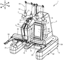
- FIG. 1 is a perspective view of a sewing machine 1.
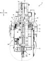
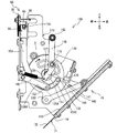
- FIG. FIG. 3 is a view of a part of the configuration inside the head 5 as seen from the front side of the sewing machine 1.
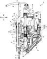
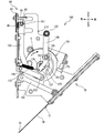
- FIG. 3 is a view of a part of the configuration inside the head 5 as viewed from the right side of the sewing machine 1.
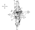
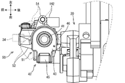
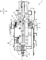
- 3 is a front view of a needle bar drive mechanism 40 and a needle bar release mechanism 50.
- FIG. 3 is a plan view of a needle bar drive mechanism 40 and a needle bar release mechanism 50.
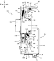
- FIG. FIG. 3 is a front view of a switching mechanism 60, a thread wiper mechanism 70, and a driving device 100.
- 3 is a right side view of a switching mechanism 60, a thread wiper mechanism 70, and a driving device 100.
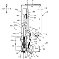
- FIG. 3 is a plan view of a switching mechanism 60, a thread wiper mechanism 70, and a drive device 100.
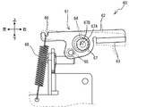
- FIG. 3 is a front view of a switching mechanism 60.
- FIG. FIG. 3 is a plan view of a switching mechanism 60, a thread wiper mechanism 70, and a drive device 100 when the needle bar release mechanism 50 is driven.
- 3 is a plan view of the switching mechanism 60, the yarn wiper mechanism 70, and the driving device 100 when the switching mechanism 60 is driven.
- FIG. FIG. 6 is a view of a part of the configuration inside the head 5 as viewed from the front side of the sewing machine 1 when the switching mechanism 60 is driven.
- FIG. 3 is a plan view of a switching mechanism 60, a yarn wiper mechanism 70, and a drive device 100 when the yarn wiper mechanism 70 is driven.
- FIG. 5 is a view of a part of the configuration inside the head 5 as viewed from the front side of the sewing machine 1 when the yarn wiper mechanism 70 is driven.
- the sewing machine 1 mainly includes a support portion 2, a pedestal portion 3, and an arm portion 4.
- the support portion 2 is a base portion of the sewing machine 1 and supports the entire sewing machine 1.
- the pedestal 3 is provided at the rear end of the support 2 and extends upward.
- the arm portion 4 extends from the upper end portion of the pedestal column portion 3 so as to face the cylinder bed 10 (described later).
- a front end portion of the arm portion 4 is a head portion 5.
- the support portion 2 is formed in a substantially U shape in plan view as a whole.
- the support part 2 includes a pair of leg parts 21 and 22 and a base part 23.
- the pair of leg portions 21 and 22 respectively extend in the front-rear direction and are arranged side by side in the left-right direction.
- the base part 23 is disposed between the leg part 21 and the leg part 22 on the rear side of each of the leg parts 21 and 22.
- the base part 23 extends in the left-right direction and connects the leg part 21 and the leg part 22.
- a lower shaft (not shown) is provided in the base unit 23.
- the lower shaft is rotationally driven by a main shaft 17 described later.
- the base portion 23 includes a cylindrical cylinder bed 10 that extends forward at substantially the center in the left-right direction.
- the upper surface of the cylinder bed 10 is a surface on which a work cloth (not shown) is arranged.
- a hook mechanism (not shown) is provided inside the cylinder bed 10.
- a driving force of a sewing machine motor 16 to be described later is transmitted to the shuttle mechanism via the lower shaft.
- the shuttle mechanism rotates a shuttle (not shown) disposed inside the tip of the cylinder bed 10.
- the shuttle accommodates a bobbin (not shown) around which a lower thread (not shown) is wound.
- a needle plate 11 having a rectangular shape in plan view is provided on the upper surface of the tip of the cylinder bed 10.
- the needle plate 11 is disposed above the shuttle.
- a needle hole 12 is formed in the needle plate 11.
- a sewing needle 9 attached to a lower end portion of a needle bar 30 (see FIG. 2) described later is inserted into the needle hole 12 of the needle plate 11.
- a pair of guide grooves 24 extending in the front-rear direction are formed on the upper surfaces of the leg portions 21 and 22.
- the pair of guide grooves 24 guide the movement of the carriage 25 in the front-rear direction.
- the carriage 25 extends in the left-right direction and is bridged between the pair of leg portions 21 and 22.
- the carriage 25 includes a moving mechanism (not shown) inside.
- the moving mechanism moves the holder 26 disposed on the front side of the carriage 25 in the left-right direction.
- An embroidery frame (not shown) that holds the work cloth is attached to the holder 26.
- the sewing machine 1 moves the embroidery frame mounted on the holder 26 by moving the carriage 25 in the front-rear direction (that is, moving the entire moving mechanism in the front-rear direction) and moving the holder 26 in the left-right direction by the moving mechanism. Move back and forth and left and right.
- a sewing machine motor 16 In the pedestal 3, a sewing machine motor 16, a control unit (not shown) of the sewing machine 1, and the like are provided.
- the sewing machine motor 16 rotationally drives a main shaft 17 provided in the arm portion 4.
- the main shaft 17 and the lower shaft in the support portion 2 are connected by a timing belt (not shown).
- the rotation of the main shaft 17 is transmitted to the lower shaft, and the main shaft 17 and the lower shaft rotate in synchronization.
- the main shaft 17 is provided inside the arm portion 4 and extends in the front-rear direction.
- the main shaft 17 drives a balance mechanism 20 and a needle bar drive mechanism 40 (described later) provided in the head 5.
- a thread stand 7 is provided on the upper surface of the arm portion 4.
- the yarn stand 7 is provided with a plurality of (for example, four) yarn stand bars 14 erected. Each thread pin 14 is inserted with a through hole of a plurality (for example, four) of thread spools 13 around which an upper thread 15 is wound.
- the yarn stand 7 can place a plurality of yarn spools 13 thereon.
- a thread tensioner 18 is provided at the top of the head 5.
- the thread tensioner 18 applies tension to the upper thread 15 supplied from the thread stand 7.
- the configuration inside the head 5 will be described later.
- An operation unit 6 is provided on the right side of the head 5.
- the operation unit 6 includes a liquid crystal display 27, a touch panel 28, a start / stop switch 29, and the like.
- Various information such as an operation screen for the user to input an instruction is displayed on the liquid crystal display 27, for example.
- the touch panel 28 receives an instruction from the user.
- the start / stop switch 29 is a switch for instructing the start or stop of sewing.
- the head 5 includes a needle bar 30, a balance mechanism 20, a needle bar drive mechanism 40, a needle bar release mechanism 50, a switching mechanism 60, a thread wiper mechanism 70, and a drive device 100. Etc. are provided.
- the needle bar 30 extends in the vertical direction within the head 5 (see FIG. 1).
- the needle bar 30 is supported by the needle bar frame 31 so as to be movable up and down.
- the needle bar frame 31 is provided with an upper support part 36 and a lower support part 37 that support the needle bar 30, and the needle bar 30 is supported by these two support parts so as to be movable up and down.
- the needle bar frame 31 is fixed to the machine frame (not shown) of the sewing machine 1 within the head 5.
- a connecting member 33 is fixed to an intermediate portion in the vertical direction of the needle bar 30 (between the upper support portion 36 and the lower support portion 37).
- the connecting member 33 includes a connecting pin 34 protruding outward in the radial direction toward the rear.
- the connecting member 33 is connected to a transmission member 51 (described later) of the needle bar release mechanism 50 and transmits the driving force of the sewing machine motor 16 to the needle bar 30.
- An annular spacer 35 made of, for example, rubber is fixed to the upper end portion of the connecting member 33.
- the spacer 35 is a contact member 61 when a contact member 61 of a switching mechanism 60 described later is positioned at a second position (described later) and the needle bar 30 is positioned at a top dead center in a range in which the needle bar 30 can move up and down.
- Abut. A screw 32 is fastened to the upper end of the needle bar 30.
- the outer diameter of the head of the screw 32 is larger than the outer diameter of the needle bar 30.
- a compression spring is fitted on the outer peripheral surface of the needle bar 30 between the head portion of the screw 32 and the upper support portion 36. Since the compression spring presses the head of the screw 32 upward, the needle bar 30 is biased upward.
- the connecting member 33 and the transmission member 51 are not connected, the needle bar 30 moves upward by the urging force of the compression spring and is located at the top dead center.
- the lower end of the needle bar 30 extends downward from the lower end of the head 5.
- a sewing needle 9 can be attached to the lower end of the needle bar 30.
- the sewing needle 9 has a hole 9A through which the upper thread 15 is inserted.
- the balance mechanism 20 is connected to the main shaft 17 (see FIG. 1) in the arm portion 4.
- the driving force of the sewing machine motor 16 is transmitted to the balance mechanism 20 via the main shaft 17.
- the balance mechanism 20 moves the balance 19 up and down in synchronization with the vertical movement of the needle bar 30.
- the needle bar 30 cooperates with the hook, and entangles the upper thread 15 passed through the eye hole 9A of the sewing needle 9 with the lower thread drawn from the bobbin accommodated in the hook.
- the balance 19 pulls the upper thread 15 entangled with the lower thread onto the needle plate 11.
- the needle bar driving mechanism 40 is a mechanism for driving the needle bar 30 up and down by converting the driving force of the sewing machine motor 16 transmitted through the main shaft 17 from a rotary motion to a vertical motion.
- the needle bar drive mechanism 40 includes a base needle bar 41, a drive member 42, and a crank rod 46.
- the base needle bar 41 is a cylindrical bar that extends in the vertical direction.
- the base needle bar 41 is provided on the rear side of the needle bar 30 and is arranged in parallel with the needle bar 30.
- the drive member 42 is externally fitted to the base needle bar 41 and is provided so as to be movable up and down and not rotatable relative to the base needle bar 41.
- the drive member 42 has an upper end portion 43, a lower end portion 44, and an intermediate portion 45.
- the upper end portion 43 and the lower end portion 44 are respectively fitted on the base needle bar 41 and are arranged with a space in the vertical direction.
- the intermediate portion 45 is provided apart from the base needle bar 41 and is connected to the upper end portion 43 and the lower end portion 44, respectively.
- a needle bar releasing mechanism 50 (described later) for connecting or blocking transmission of driving force to the needle bar 30 is provided.
- the crank rod 46 connects the lower end 44 of the drive member 42 and a needle bar crank (not shown).
- the needle bar crank is fixed to the front end of the upper shaft and rotates integrally with the main shaft 17. Due to the rotation of the main shaft 17 and the needle bar crank, the drive member 42 reciprocates in the vertical direction along the base needle bar 41.
- the needle bar release mechanism 50 is connected to transmit the driving force to the needle bar 30
- the driving force of the sewing machine motor 16 transmitted to the needle bar driving mechanism 40 via the main shaft 17 is transmitted to the needle bar 30.
- the needle bar release mechanism 50 and the needle bar 30 reciprocate in the vertical direction in conjunction with the drive member 42 that reciprocates in the vertical direction along the base needle bar 41.
- the needle bar release mechanism 50 is a mechanism for connecting or blocking transmission of the driving force of the sewing machine motor 16 from the needle bar driving mechanism 40 to the needle bar 30.
- the needle bar release mechanism 50 includes a transmission member 51 and a winding spring 55.
- the transmission member 51 is externally fitted to the base needle bar 41 and is provided so as to be movable up and down and rotatable with respect to the outer peripheral surface of the base needle bar 41.
- the transmission member 51 is provided with an upper engagement protrusion 52, a lower engagement protrusion 53, and a contact post 54 (see FIG. 4).
- the upper engagement protrusion 52 and the lower engagement protrusion 53 protrude radially outward from the outer peripheral surface of the transmission member 51 and have a gap in the vertical direction.
- the upper engagement protrusion 52 is formed on an inclined surface whose upper surface is inclined diagonally to the left (see FIG. 4).
- the connection pin 34 of the needle bar 30 is engaged between the upper engagement protrusion 52 and the lower engagement protrusion 53.
- the abutment column 54 is formed in a bar shape extending in the vertical direction, and is provided at a portion protruding radially outward from the outer peripheral surface of the transmission member 51.
- a first pin 142 (described later) of the driving device 100 contacts the contact column 54 from the rear side. When the contact pillar 54 is pressed forward by the first pin 142 (indicated by a one-dot chain line in the figure), the transmission member 51 rotates counterclockwise in plan view (see FIG. 5).
- the upper engagement protrusion 52 and the lower engagement protrusion 53 of the transmission member 51 move to the right front side of the base needle bar 41. In this case, the engagement between the upper engagement protrusion 52 and the lower engagement protrusion 53 and the connecting pin 34 of the needle bar 30 is released.
- the needle bar 30 moves upward by the urging force of the compression spring and is positioned at the top dead center (see FIG. 3).
- a winding spring 55 is connected to the upper part of the transmission member 51.
- the winding spring 55 is fitted on the upper end portion 43 of the drive member 42.
- the winding spring 55 urges the transmission member 51 clockwise with respect to the drive member 42 in plan view.
- the contact pillar 54 of the transmission member 51 is not pressed by the first pin 142 of the drive device 100, the transmission member 51 is rotated by the winding spring 55.
- the upper engagement protrusion 52 and the lower engagement protrusion 53 move to the front of the base needle bar 41. That is, the upper engagement protrusion 52 and the lower engagement protrusion 53 move to positions where the connection pin 34 of the needle bar 30 can be engaged.
- the switching mechanism 60 is a mechanism that switches the position of the contact member 61 between the first position and the second position. As shown in FIGS. 6 to 8, the switching mechanism 60 is disposed on the upper front side of the driving apparatus 100 described later.
- the switching mechanism 60 includes a contact member 61 and a tension spring 68.
- the contact member 61 is a member that positions the needle bar 30 when the needle bar 30 is located at a top dead center in a range in which the needle bar 30 can move up and down.
- the contact member 61 includes a main body 62, a contact portion 63, a support hole 64, an operating pin 65, and a hanging portion 66.
- the main body 62 is a plate-like body that extends long in the left-right direction and has the front-rear direction arranged in the thickness direction.
- a support hole 64 penetrating in the thickness direction is formed substantially at the center in the left-right direction of the main body 62.
- the eccentric nut 67 is inserted into the support hole 64.
- the eccentric nut 67 is fixed to the needle bar frame 31 with a screw 69 (see FIG. 2).
- a contact portion 63 is provided at the right end portion of the main body portion 62.
- the contact portion 63 protrudes rearward from the lower end of the right end portion of the main body portion 62 and is formed in a U shape in plan view.
- the contact portion 63 contacts the spacer 35 of the connecting member 33 when the contact member 61 is located at the second position and the needle bar 30 is located at the top dead center.
- a notch-like hanging portion 66 is formed at the left end portion of the main body portion 62.
- One end of a tension spring 68 is hooked on the hanging portion 66.
- the other end of the tension spring 68 is hooked on a retaining hole 112A (see FIG. 6) of the gear frame 110 of the driving device 100.
- the contact member 61 is positioned at a first position where the contact portion 63 is urged upward by the tension spring 68 with an eccentric nut 67 inserted through the support hole 64 as a fulcrum.
- the contact portion 63 does not contact the spacer 35 of the connecting member 33 even if the needle bar 30 is positioned at the top dead center.
- An operating pin 65 protruding rearward is provided at the lower left of the support hole 64.
- a second pin 151 (described later) of the driving device 100 abuts on the operation pin 65.
- the contact member 61 is located at a second position (see FIG. 12) in which the contact portion 63 is moved downward with the eccentric nut 67 as a fulcrum.
- the contact portion 63 contacts the spacer 35 of the connecting member 33 if the needle bar 30 is positioned at the top dead center.
- the eccentric nut 67 is engaged with the position of the shaft center 67 ⁇ / b> A of the hole portion into which the screw 69 fixed to the needle bar frame 31 is fitted and the support hole 64, and the rotation center of the contact member 61. It is formed by shifting (decentering) the position of the axial center 67B of the boss portion.
- the illustration of the screw 69 for fixing the eccentric nut 67 is omitted for convenience of explanation.
- the position of the shaft center 67 ⁇ / b> A of the eccentric nut 67 is a fixed position with respect to the needle bar frame 31.
- the position of the shaft center 67B is shifted in the circumferential direction around the shaft center 67A in accordance with the angle at which the eccentric nut 67 is fixed to the needle bar frame 31 as indicated by the one-dot chain line in the figure. That is, the eccentric nut 67 can shift the position of the rotation center of the contact member 61 by changing the angle at which the screw 69 is loosened and fixed.
- the position of the contact portion 63 is shifted upward or downward.
- the eccentric nut 67 has a position where the contact portion 63 contacts the spacer 35 of the connecting member 33 when the contact member 61 is positioned at the second position and the needle bar 30 is positioned at the top dead center. It can be adjusted in the vertical direction.
- the thread wiper mechanism 70 wipes the end of the upper thread 15 passed through the eye hole 9A of the sewing needle 9 from below the sewing needle 9 at the end of sewing or when changing the thread. This is a mechanism for preventing the upper thread 15 from being caught in sewing.
- the yarn wiper mechanism 70 is assembled to a lower rear portion of the driving device 100 described later, and is provided at a lower portion inside the head 5.
- the yarn wiper mechanism 70 includes a yarn wiper member 71 and a guide member 76.
- the yarn wiper member 71 is a plate-like member that extends obliquely from the upper oblique rear to the lower oblique front.
- the yarn wiper member 71 has a base 72, a support part 73, an arm part 74, and a hook part 75.
- the base 72 is engaged with a groove 77 formed in the guide member 76.
- a support portion 73 that protrudes above the base portion 72 is formed at the left rear end portion of the base portion 72.
- the support portion 73 has a hole portion (not shown) penetrating in the left-right direction, and a stepped screw 162 (described later) that engages with the connecting rod 160 of the drive device 100 is inserted.
- the base portion 72 is guided by the groove portion 77 by the driving force transmitted from the driving device 100, and moves between an upper obliquely rearward position and a lower obliquely forward position.
- the arm portion 74 projects from the front end portion of the base portion 72 obliquely downward and forward.
- the arm portion 74 is formed narrower in the left-right direction than the base portion 72 and extends longer.
- a hook portion 75 is formed at the front end portion of the arm portion 74.
- the hook portion 75 is positioned below the sewing needle 9 (see FIG. 3) when the thread wiper member 71 moves obliquely downward and forward.
- the thread wiper member 71 can hook and hold the upper thread 15 that hangs downward from the eye hole 9 ⁇ / b> A of the sewing needle 9 on the hook portion 75.
- the guide member 76 has a rectangular plate shape and is assembled to the lower surface of the thread wiper fixing portion 115 of the gear frame 110 (described later) of the driving device 100.
- the guide member 76 engages the base portion 72 of the yarn wiper member 71 with the groove portion 77 and holds the base portion 72 between the yarn wiper fixing portion 115 and the guide member 76.
- An opening 115 ⁇ / b> A is formed on the upper surface of the yarn wiper fixing portion 115.
- the support portion 73 of the yarn wiper member 71 is exposed to the upper portion of the yarn wiper fixing portion 115 from the opening 115A.
- the driving device 100 is a device that drives the needle bar release mechanism 50, the switching mechanism 60, and the thread wiper mechanism 70 by the driving force of one power source.
- the driving device 100 includes a gear frame 110, a pulse motor 120, a sector gear 130, a first link rod 140, a second link rod 150, a connecting rod 160, and a photo sensor 170.
- the gear frame 110 is a frame that is formed by bending a metal plate and supports each component that constitutes the driving device 100.
- the gear frame 110 has a main body 111, front frames 112 and 113, a sensor fixing part 114, and a thread wiper fixing part 115.
- the main body 111 is arranged in the head 5 with the thickness direction being set in the left-right direction (see FIG. 2).
- the main body 111 extends in the vertical direction, and the lower side is formed wide in the front-rear direction.
- the sector gear 130 is disposed on the right plate surface (referred to as “front surface”) side of the main body 111, and the pulse motor 120 is disposed on the left plate surface (referred to as “rear surface” for convenience).
- a support shaft 117 see FIG.
- a support shaft 118 (see FIG. 7) that supports the first link rod 140 so as to be swingable is fixed to the support shaft 117 obliquely rearward and protrudes rightward from the main body 111.
- a support shaft 119 that supports a front end portion of a support rod 155 (described later) in a swingable manner is fixed in front of the support shaft 117 and protrudes rightward from the main body 111.
- the front frames 112 and 113 are front side portions of the main body 111 and are formed by bending the surface in the rearward direction, and are provided in two parts at the top and bottom. Screw holes (not shown) are formed at two locations on the upper front frame 112 and at one location on the lower front frame 113. A fixing screw 101 is inserted into each screw hole and fastened to the needle bar frame 31. The front frames 112 and 113 fix the gear frame 110 to the needle bar frame 31. A portion on the left side of the upper end portion of the front frame 112 is folded back to form a pin guide portion 116.
- the pin guide portion 116 is formed with a support hole 116A (see FIG. 7) that penetrates in the left-right direction and is vertically long.
- the second pin 151 fixed to the upper end portion of the second link rod 150 is inserted through the support hole 116A.
- the support hole 116A supports the second pin 151 so as to be movable up and down.
- a retaining hole 112A (see FIG. 6) is formed in the upper portion of the front frame 112.
- the switching mechanism 60 is disposed on the upper front side of the drive device 100.
- the arrangement position of the switching mechanism 60 is a position above the front frame 112.
- the other end of the tension spring 68 of the switching mechanism 60 is hooked on the retaining hole 112A.
- the contact portion 63 of the contact member 61 is urged upward by the tension spring 68 with the eccentric nut 67 as a fulcrum.
- the sensor fixing part 114 is a part of the rear part of the main body part 111, and is a part formed by bending the surface upward and obliquely forward.
- the sensor fixing part 114 is provided behind the support shaft 117.
- a photo sensor 170 is fixed to the sensor fixing portion 114.
- the thread wiper fixing portion 115 is a lower portion of the main body portion 111 and is a portion formed by bending the surface upward and obliquely forward.
- An opening 115A formed on the upper surface of the thread wiper fixing portion 115 extends in the front-rear direction. As described above, the guide member 76 of the yarn wiper mechanism 70 is fixed to the lower surface of the yarn wiper fixing portion 115.
- the pulse motor 120 is fixed to the back surface of the main body 111.
- the output shaft 121 of the pulse motor 120 extends in the left-right direction, and the right end portion projects from the surface side of the main body 111.
- a drive gear 122 is fixed to the right end portion of the output shaft 121.
- the gear teeth of the drive gear 122 mesh with the gear teeth 131 of the sector gear 130.
- the pulse motor 120 is driven in accordance with an instruction from the control unit of the sewing machine 1 to rotate the sector gear 130.
- the sector gear 130 is a rotating body having a substantially disk shape and gear teeth 131 formed on a part of the outer peripheral portion.
- the sector gear 130 is disposed on the surface side of the main body 111 and is rotatably supported by a support shaft 117 provided on the main body 111.
- the gear tooth 131 meshes with the drive gear 122 provided on the output shaft 121 of the pulse motor 120.
- the pulse motor 120 swings the sector gear 130 in the formation range of the gear teeth 131.
- the sector gear 130 is provided with a detection part 132, a protruding part 133, a guide hole 134, a groove cam 135 and a plate cam 136.
- the detecting unit 132 is provided on the outer peripheral portion of the sector gear 130 on the side opposite to the gear teeth 131.
- the detector 132 protrudes outward in the radial direction of the sector gear 130 and extends in the circumferential direction.
- the detection unit 132 is used to detect the origin position in the rotation of the sector gear 130 by the photo sensor 170.
- the photo sensor 170 is a photo interrupter including a light receiving element and a light emitting element.
- the control unit (not shown) of the sewing machine 1 determines the rotational position of the sector gear 130. Judged to be at the origin position.
- the gear teeth 131 are arranged at positions on the outer periphery of the sector gear 130 from above the support shaft 117 to the front.
- the protruding portion 133 is an outer peripheral portion of the sector gear 130 and protrudes radially outward at a lower portion when the sector gear 130 is at the origin position.
- the protrusion 133 is provided with a hole (not shown) penetrating in the left-right direction, and the rotating shaft 161 is inserted therethrough.
- the rotating shaft 161 is provided at the front end of the connecting rod 160 that transmits driving force to the yarn wiper mechanism 70.
- the sector gear 130 moves the protrusion 133 by rotation, and operates the connecting rod 160.
- the guide hole 134 is formed on the plate surface of the sector gear 130 and above the support shaft 117 when the sector gear 130 is at the origin position.
- the guide hole 134 is an opening that is formed in an arc shape centered on the support shaft 117 and penetrates the sector gear 130 in the thickness direction.
- the support shaft 118 of the first link rod 140 is inserted into the guide hole 134.
- the guide hole 134 is formed with a length that does not contact the support shaft 118 in the rotation range of the sector gear 130.
- the groove cam 135 is a plate surface of the sector gear 130 and is formed below the support shaft 117 when the sector gear 130 is at the origin position.
- the groove cam 135 is a groove formed in an arc shape with the support shaft 117 as the center.
- the groove cam 135 is engaged with the left end portion of the cam follower 152 provided at the lower end portion of the second link rod 150.
- the cam follower 152 abuts on the outer peripheral wall portion of the groove cam 135 in the rotation range of the sector gear 130.
- the outer peripheral wall portion of the groove cam 135 includes a first outer peripheral wall portion 135B, a second outer peripheral wall portion 135C, and a step portion 135A.
- the step portion 135A is formed between the first outer peripheral wall portion 135B and the second outer peripheral wall portion 135C.
- the step portion 135A is located below the support shaft 117
- the first outer peripheral wall portion 135B is located on the left side of the step portion 135A
- the second outer peripheral wall portion 135C is stepped.
- the first outer peripheral wall portion 135B and the second outer peripheral wall portion 135C each form an arc shape with the support shaft 117 as the center.
- the radius of the first outer peripheral wall portion 135B is larger than the radius of the second outer peripheral wall portion 135C.
- the plate cam 136 is formed on the plate surface of the sector gear 130 in a disc shape centered on the support shaft 117 and is provided integrally with the sector gear 130.
- the plate cam 136 has an operating portion 137 protruding outward in the radial direction at a lower portion of the support shaft 117 when the sector gear 130 is at the origin position.
- the cam receiving portion 141 of the first link rod 140 abuts on the outer peripheral portion of the plate cam 136.
- the plate cam 136 moves the cam receiving portion 141 in the operating portion 137 to operate the first link rod 140.
- the first link bar 140 is a bar-shaped plate that extends in the up-down direction with the thickness direction arranged in the left-right direction.
- the first link bar 140 is swingably supported by the support shaft 118 at a position below the center in the vertical direction.
- the portion of the first link bar 140 above the support shaft 118 extends straight upward from the position of the support shaft 118.
- a first pin 142 that transmits a driving force to the needle bar release mechanism 50 is provided at the upper end of the first link bar 140.
- the first pin 142 protrudes to the right side of the first link bar 140.
- the first pin 142 is disposed above the sector gear 130 and is disposed on the rear side of the abutment column 54 of the needle bar release mechanism 50.
- a cam receiving portion 141 and an urging portion 143 are provided in a portion below the support shaft 118 of the first link rod 140.
- the cam receiver 141 extends downward from the position of the support shaft 118.
- the lower end portion of the cam receiving portion 141 is disposed on the right side of the support shaft 117 of the sector gear 130 and abuts on the plate cam 136.
- the urging portion 143 extends obliquely downward from the lower position of the support shaft 118.
- a retaining hole 144 is formed at the lower end of the urging portion 143.
- One end of a tension spring 145 is hooked on the retaining hole 144.
- the other end of the tension spring 145 is hooked in a retaining hole 112B formed in the lower end portion of the front frame 112 of the gear frame 110.
- the tension spring 145 biases the lower end portion of the biasing portion 143 forward.
- the first pin 142 of the first link bar 140 is urged rearward by the tension spring 145 with the support shaft 118 as a fulcrum.
- the 1st pin 142 is maintained in the state contact
- the second link rod 150 is a rod-shaped plate body that extends in the vertical direction with the thickness direction arranged in the horizontal direction.
- the portion of the second link bar 150 that is above the center in the vertical direction extends straight in the vertical direction.
- a second pin 151 that transmits a driving force to the switching mechanism 60 is provided at the upper end of the second link rod 150.
- the second pin 151 protrudes to the right side of the second link rod 150, is inserted from the left side to the right side into a support hole 116A formed in the pin guide portion 116 of the gear frame 110, and is prevented from being detached by a retaining ring.
- the second pin 151 is disposed below the operation pin 65 of the switching mechanism 60.
- a cam follower 152 is provided at the lower end of the second link rod 150.
- the cam follower 152 is a columnar bar that extends in the left-right direction and has an outer diameter at an intermediate portion larger than outer diameters at both left and right ends.
- the right end portion of the cam follower 152 is fixed to the rear end portion of the support bar 155 whose front end portion is supported by the support shaft 119.
- the support bar 155 is a bar-shaped plate body that is disposed in the left-right direction and extends in the front-rear direction.
- the second link bar 150 is disposed on the left side of the support bar 155.
- An intermediate portion of the cam follower 152 is engaged with a hole portion (not shown) formed in the lower end portion of the second link rod 150.
- the left end portion of the cam follower 152 is engaged with the groove cam 135. Since the position of the rear end portion of the support rod 155 is positioned by the swing range of the support rod 155 with the support shaft 119 as a fulcrum, the cam follower 152 is positioned below the support shaft 117 of the sector gear 130 at the groove cam 135.
- the first outer peripheral wall portion 135B, the second outer peripheral wall portion 135C, or the stepped portion 135A is abutted.
- the cam follower 152 slides on the first outer peripheral wall portion 135B, the second outer peripheral wall portion 135C, or the step portion 135A of the groove cam 135.
- the second outer peripheral wall portion 135C is formed in an arc shape centering on the support shaft 117 at a position closer to the support shaft 117 in the radial direction than the first outer peripheral wall portion 135B.
- the connecting rod 160 is a rod-shaped plate body that extends in the front-rear direction by arranging the thickness direction in the left-right direction.
- a rotating shaft 161 is provided at the front end of the connecting rod 160.
- the rotating shaft 161 protrudes to the left side of the connecting rod 160.
- the rotating shaft 161 is inserted into a hole (not shown) formed in the protruding portion 133 of the sector gear 130 and is prevented from coming off on the left side of the protruding portion 133.
- the connecting rod 160 is supported by the rotating shaft 161 so as to be swingable with respect to the sector gear 130.
- a hole (not shown) penetrating in the thickness direction is provided at the rear end of the connecting rod 160, and a stepped screw 162 is inserted from the left side.
- the stepped screw 162 is also inserted into a hole (not shown) provided in the support portion 73 of the yarn wiper member 71, and the nut 163 is fastened from the right side.
- the connecting rod 160 is supported by a stepped screw 162 so as to be swingable with respect to the yarn wiper member 71.
- the connecting member 33 of the needle bar 30 engages with the transmission member 51 of the needle bar release mechanism 50. That is, the sewing machine 1 is in a connected state in which the transmission of the driving force of the sewing machine motor 16 is connected between the needle bar 30 and the main shaft 17 via the needle bar drive mechanism 40 by the needle bar release mechanism 50.
- the sector gear 130 of the driving apparatus 100 is located at the origin position (see FIG. 7) detected by the photosensor 170. That is, the needle bar release mechanism 50, the switching mechanism 60, and the thread wiper mechanism 70 are in a non-driven state.
- the contact member 61 is located at the first position. Therefore, even if the needle bar 30 moves up and down during sewing of the sewing machine 1, the spacer 35 of the connecting member 33 does not come into contact with the contact portion 63.
- the sewing machine 1 can replace the upper thread 15 supplied from the plurality of thread spools 13 placed on the thread stand 7 with the upper thread 15 suitable for the sewing contents.
- the sewing machine 1 includes a threading mechanism (not shown) and can thread the upper thread 15 through the eye hole 9A of the sewing needle 9. Due to the threading operation and the thread wiping operation of the upper thread 15 performed after threading, the control unit (not shown) of the sewing machine 1 positions the eye hole 9A in a state where the needle bar 30 is blocked from the transmission of the driving force. To do.
- the control unit first drives the needle bar release mechanism 50 to interrupt the transmission of the driving force of the sewing machine motor 16 to the needle bar 30.
- the control unit applies a voltage corresponding to a predetermined first pulse to the pulse motor 120.
- the sector gear 130 rotates by a first angle counterclockwise as viewed from the right side from the origin position.
- the plate cam 136 integrated with the sector gear 130 rotates by a first angle counterclockwise as viewed from the right side.
- the operating portion 137 located below the support shaft 117 at the origin position moves to the rear of the support shaft 117 and presses the cam receiving portion 141 of the first link rod 140 backward.
- the cam receiving portion 141 moves rearward, the first link rod 140 rotates counterclockwise as viewed from the right side around the support shaft 118 and moves the first pin 142 forward.
- the drive device 100 does not move the second link rod 150 and does not drive the switching mechanism 60. That is, the switching mechanism 60 is in a non-driven state in the shut-off transition state in which the connection state shifts to a shut-off state in which transmission of the driving force is interrupted between the needle bar 30 and the main shaft 17. Therefore, the contact member 61 is located at the first position. Further, the protruding portion 133 of the sector gear 130 moves rearward and presses the yarn wiper member 71 obliquely upward and rearward via the connecting rod 160. Therefore, the driving device 100 does not position the hook portion 75 of the thread wiper member 71 below the sewing needle 9 and does not drive the thread wiper mechanism 70.
- the first pin 142 presses the contact column 54 of the transmission member 51 of the needle bar release mechanism 50 forward.
- the transmission member 51 rotates counterclockwise in plan view around the base needle bar 41.
- the upper engagement protrusion 52 and the lower engagement protrusion 53 of the transmission member 51 move obliquely forward to the right of the base needle bar 41 and release the engagement with the connecting pin 34 of the needle bar 30.
- the needle bar 30 is released from the connection with the transmission member 51, is urged by a compression spring (not shown), moves upward, and is located at the top dead center (see FIG. 2).
- the control unit drives the pulse motor 120, rotates the sector gear 130 clockwise as viewed from the right side, and returns it to the origin position based on the detection result of the photosensor 170.
- the operating portion 137 of the plate cam 136 returns to the lower side of the support shaft 117 and finishes pressing the cam receiving portion 141.
- the urging portion 143 of the first link rod 140 is moved forward by the tension spring 145.
- the first link rod 140 rotates clockwise about the support shaft 118 as viewed from the right side, and returns the first pin 142 to a position above the support shaft 118.
- the transmission member 51 of the needle bar release mechanism 50 is rotated clockwise by the winding spring 55 in plan view.
- the upper engagement protrusion 52 and the lower engagement protrusion 53 move to the front of the base needle bar 41, that is, to a position where the connection pin 34 of the needle bar 30 can be engaged.
- the sector gear 130 is located at the origin position, so the switching mechanism 60 is in a non-driven state. Therefore, the contact member 61 is located at the first position.
- the transmission of the driving force to the needle bar 30 shifts from the blocked state to the connected state.
- the control unit presses the needle bar 30 with the contact member 61 to position the eye hole 9A for the threading operation.
- the control unit applies a voltage corresponding to a predetermined second pulse to the pulse motor 120.
- the sector gear 130 rotates by a second angle clockwise from the origin position when viewed from the right side.
- the cam follower 152 of the second link rod 150 slides beyond the step portion 135A from a position where it abuts on the first outer peripheral wall portion 135B of the groove cam 135, and abuts on the second outer peripheral wall portion 135C.
- the cam follower 152 moves upward as compared with the case where the cam follower 152 abuts on the first outer peripheral wall portion 135B. Therefore, the second link rod 150 moves upward, and the operating pin 65 of the contact member 61 is pressed upward by the second pin 151.
- the contact member 61 is located at the second position.
- the contact portion 63 of the contact member 61 is urged by a compression spring and contacts the spacer 35 of the connecting member 33 of the needle bar 30 located at the top dead center.
- the needle bar 30 is brought into contact with the contact member 61 so that the vertical position is determined, and the eye 9A of the sewing needle 9 attached to the lower end of the needle bar 30 is positioned.
- the plate cam 136 rotates clockwise as viewed from the right side.
- the operating part 137 moves in front of the support shaft 117 and leaves the cam receiving part 141 of the first link rod 140. Therefore, the driving device 100 does not drive the first link bar 140 and does not drive the needle bar release mechanism 50.
- the protruding portion 133 of the sector gear 130 moves forward, and moves the yarn wiper member 71 diagonally forward and downward through the connecting rod 160.
- the drive device 100 moves the hook portion 75 of the thread wiper member 71 diagonally forward and downward, but does not place it below the sewing needle 9. Therefore, in the threading operation, the driving device 100 does not drive the thread wiper mechanism 70.
- a threading mechanism (not shown) is driven, and the upper thread 15 is threaded through the eye 9A of the sewing needle 9 positioned on the contact member 61.
- the control unit performs a thread wiper operation. As shown in FIG. 13, the control unit applies a voltage corresponding to a predetermined third pulse to the pulse motor 120.
- the sector gear 130 further rotates from the position rotated by the threading operation by a third angle clockwise as viewed from the right side.
- the projecting portion 133 of the sector gear 130 moves further forward, and moves the yarn wiper member 71 obliquely downward and forward through the connecting rod 160.
- the driving device 100 positions the hook portion 75 of the thread wiper member 71 below the sewing needle 9 and drives the thread wiper mechanism 70.
- the hook portion 75 is passed through the eye hole 9 ⁇ / b> A and holds the end portion of the upper thread 15 that hangs down below the sewing needle 9.
- the cam follower 152 of the second link rod 150 slides on the second outer peripheral wall portion 135 ⁇ / b> C of the groove cam 135 while the sector gear 130 rotates by the third angle. Therefore, the second link bar 150 is maintained in a state of moving upward. Thereby, the operation pin 65 of the contact member 61 is maintained in a state where it is pressed upward by the second pin 151. Therefore, the contact member 61 is maintained at the second position. Then, the needle bar 30 abuts against the abutting member 61 and is kept positioned by the urging force of the compression spring.
- the plate cam 136 further rotates clockwise as viewed from the right side.
- the operating portion 137 is further away from the cam receiving portion 141 of the first link rod 140. Therefore, the driving device 100 does not drive the first link bar 140 and does not drive the needle bar release mechanism 50.
- the control unit drives the pulse motor 120, rotates the sector gear 130 counterclockwise as viewed from the right side, and returns it to the origin position based on the detection result of the photosensor 170.
- the protruding portion 133 of the sector gear 130 moves rearward, and moves the yarn wiper member 71 diagonally upward and backward via the connecting rod 160.
- the end portion of the upper thread 15 held by the hook portion 75 is threaded behind the sewing needle 9 by the movement of the thread wiper member 71.
- the cam follower 152 of the second link rod 150 is returned to the state in contact with the first outer peripheral wall portion 135B. Therefore, the second link rod 150 moves downward, and the pressing of the operating pin 65 by the second pin 151 is terminated.
- the plate cam 136 also rotates, but the operating portion 137 does not contact the cam receiving portion 141 of the first link rod 140.
- the control unit drives the sewing machine motor 16 to move the drive member 42 of the needle bar drive mechanism 40 upward along the base needle bar 41.
- the transmission member 51 of the needle bar release mechanism 50 is moved upward by the drive member 42, the upper engagement protrusion 52 contacts the connecting pin 34 of the needle bar 30 from below.
- the connecting pin 34 presses the upper surface of the upper engaging projection 52 formed on the inclined surface, and rotates the transmission member 51 counterclockwise in plan view.
- the transmission member 51 moves further upward and the upper engagement protrusion 52 is positioned above the connecting pin 34, the upper engagement protrusion 52 and the lower engagement protrusion 53 are moved forward of the base needle bar 41 by the winding spring 55. Move to.
- connection pin 34 is sandwiched between the upper engagement protrusion 52 and the lower engagement protrusion 53, and the connection member 33 of the needle bar 30 engages with the transmission member 51 of the needle bar release mechanism 50. That is, the sewing machine 1 is in a connected state in which the transmission of the driving force of the sewing machine motor 16 is connected between the needle bar 30 and the main shaft 17.
- the switching mechanism 60 can switch the arrangement position of the contact member 61 to the first position in the connected state. Even when the driving force of the sewing machine motor 16 is transmitted and the needle bar 30 reciprocates up and down, the needle bar 30 does not contact the contact member 61 located at the first position. Therefore, the sewing machine 1 can prevent the generation of sound and vibration due to the contact between the needle bar 30 and the contact member 61.
- the switching mechanism 60 can switch the arrangement position of the contact member 61 to the second position in the connection transition state. Therefore, the sewing machine 1 can reliably position the needle bar 30 in the vertical direction by bringing the needle bar 30 into contact with the contact member 61 in the connection transition state.
- the needle bar release mechanism 50 and the switching mechanism 60 can be driven by a pulse motor 120 which is a common actuator, the number of parts of the sewing machine 1 can be reduced and the production cost can be reduced. Furthermore, since the needle bar release mechanism 50, the switching mechanism 60, and the thread wiper mechanism 70 can be driven by a pulse motor 120 that is a common actuator, the number of parts of the sewing machine 1 can be further reduced, and the production cost can be further reduced. Can be planned.
- the driving force of one pulse motor 120 is transmitted to the needle bar release mechanism 50 by the cam mechanism having the plate cam 136 and the cam receiving portion 141, and is transmitted to the switching mechanism 60 by the cam mechanism having the groove cam 135 and the cam follower 152.
- it can be transmitted to the yarn wiping mechanism 70 by a crank mechanism having the protrusion 133 and the connecting rod 160. Therefore, the sewing machine 1 can drive the needle bar release mechanism 50, the switching mechanism 60, and the thread wiper mechanism 70 in a mechanically interlocked manner by driving only one pulse motor 120.
- each mechanism is mechanically interlocked, it is difficult for each operation timing to be shifted.
- the sewing machine 1 can adjust the contact position between the needle bar 30 and the contact member 61 when the needle bar 30 is located at the top dead center. , Can be adjusted to the proper position. Therefore, the sewing machine 1 can position the needle bar 30 at an appropriate position even if the constituent members of the mechanisms have variations in dimensions.
- the switching mechanism 60 is driven by a cam mechanism including the groove cam 135 and the cam follower 152
- the switching mechanism 60 may be driven by a cam mechanism including a plate cam and a cam receiving portion, or may be driven by a crank mechanism including a connecting rod.
- the needle bar release mechanism 50 may be driven by a cam mechanism using a groove cam and a cam follower, or may be driven by a cam mechanism using a groove cam 135 and a cam follower 152.
- the yarn wiper mechanism 70 may be driven by a cam mechanism including a groove cam and a cam follower, or a plate cam and a cam receiving portion.
- the second position of the contact member 61 is adjusted in the vertical direction by the eccentric nut 67, but may be adjusted by other means capable of shifting the position of the rotation center of the contact member 61.
- the driving device 100 corresponds to the “driving means” in the present invention.
- the pulse motor 120 corresponds to an “actuator”.
- the sector gear 130 corresponds to a “rotating body”.
- the support shaft 117 corresponds to a “rotary shaft”.
- the eccentric nut 67 corresponds to “adjusting means”.
- the operation pin 65 corresponds to a “reception unit”.
Landscapes
- Engineering & Computer Science (AREA)
- Textile Engineering (AREA)
- Mechanical Engineering (AREA)
- Sewing Machines And Sewing (AREA)
Abstract
針棒(30)を駆動源との接続から釈放した際に針棒(30)に当接する当接部材(61)が、針棒(30)を駆動源に接続して上下に移動させた際には針棒(30)に当接しないようにするミシン(1)を提供する。セクタギア(130)はパルスモータ(120)の駆動力で回転し、カム機構及びクランク機構によって、針棒釈放機構(50)、切替機構(60)及び糸払い機構(70)を駆動する。接続状態、遮断状態及び遮断移行状態において、切替機構(60)の当接部材(61)は、引張バネ(68)によって第一位置に位置する。接続移行状態において、セクタギア(130)が回転すると、溝カム(135)に係合するカムフォロア(152)が設けられた第二リンク棒(150)が切替機構(60)を駆動し、当接部材(61)を第二位置に移動する。針棒(30)が上死点に位置する場合、当接部材(61)は、第二位置において針棒(30)に当接し、第一位置においては針棒(30)に当接しない。
Description
本発明は、針棒釈放機構を備えたミシンに関する。
従来、駆動源から針棒への駆動力の伝達を分断可能な針棒釈放機構を備えたミシンが知られている。例えば特許文献1に記載のミシンの針棒は、針棒釈放機構によって駆動源との接続から釈放される。釈放された針棒は、針棒に外嵌された圧縮バネのバネ力によって上方へ移動する。針棒は、上下に移動可能な範囲における上死点の位置で、当接部材に当接して係止される。
ところで、針棒が駆動源に接続されて上下に往復移動する際にも、針棒が上死点の位置では当接部材に当接する。針棒は、上死点において上下方向への移動速度がゼロであるものの、当接部材と当接することで、音や振動を僅かに発生する可能性があった。
本発明は、針棒を駆動源との接続から釈放した際に針棒に当接する当接部材が、針棒を駆動源に接続して上下に移動させた際には針棒に当接しないようにするミシンを提供することを目的とする。
本発明の一態様に係るミシンは、ミシンモータの駆動力が主軸を介して伝達されて上下に移動する針棒と、前記針棒と前記主軸との間で駆動力の伝達を接続又は遮断する針棒釈放機構と、前記針棒釈放機構を駆動する駆動手段とを備えたミシンにおいて、前記針棒が上下に移動可能な範囲における上死点に位置する場合に前記針棒に当接可能な当接部材と、前記当接部材の配置位置を、前記針棒釈放機構によって前記針棒と前記主軸との間の駆動力の伝達が接続された接続状態、前記針棒と前記主軸との間の駆動力の伝達が遮断された遮断状態、及び前記接続状態から前記遮断状態に移行する遮断移行状態においては、前記針棒が前記上死点に位置しても前記針棒に当接しない第一位置と、前記遮断状態から前記接続状態に移行する接続移行状態において、前記針棒が前記上死点に位置する場合に、前記針棒に当接する第二位置との間で切り替える切替機構とを備えることを特徴とする。
本態様に係るミシンによれば、切替機構は、接続状態において、当接部材の配置位置を第一位置に切り替えることができる。ミシンモータの駆動力が伝達され、針棒が上下に往復移動しても、針棒は当接部材に当接しない。故にミシンは、針棒と当接部材との当接に起因する音や振動の発生を防止することができる。また切替機構は、接続移行状態において、当接部材の配置位置を第二位置に切り替えることができる。故にミシンは、接続移行状態において、針棒を当接部材に当接させ、針棒の上下方向の位置を確実に位置決めすることができる。
以下、図面を参照し、本発明の一実施形態について説明する。まず、ミシン1の構成について説明する。以下の説明では、図1の上側、下側、左斜め下側、右斜め上側、左斜め上側、右斜め下側を、夫々、ミシン1の上側、下側、前側、後側、左側、右側と定義する。
図1に示すように、ミシン1は、支持部2、脚柱部3、及びアーム部4を主に備える。支持部2は、ミシン1の土台部であり、ミシン1全体を支持する。脚柱部3は、支持部2の後端部に設けられ、上方へ延びる。アーム部4は、脚柱部3の上端部から前方へ向けて、シリンダベッド10(後述)に対向して延びる。アーム部4の前端部は頭部5である。
支持部2は、全体として平面視、略U字形状に形成される。支持部2は、一対の脚部21,22と、基台部23とを備える。一対の脚部21,22は、夫々前後方向に延び、左右方向に並べて配置される。基台部23は、脚部21,22夫々の後部側で、脚部21と脚部22との間に配置される。基台部23は、左右方向に延び、脚部21と脚部22とを接続する。
基台部23内には、下軸(図示略)が設けられる。下軸は、後述する主軸17によって回転駆動される。基台部23は、左右方向略中央に、前方へ延びる筒状のシリンダベッド10を備える。シリンダベッド10の上面は、加工布(図示略)が配置される面である。シリンダベッド10の内部には、釜機構(図示略)が設けられる。釜機構には、下軸を介し、後述するミシンモータ16の駆動力が伝達される。釜機構は、シリンダベッド10の先端部内部に配置される釜(図示略)を回転駆動する。釜は、下糸(図示略)が巻回されたボビン(図示略)を収容する。シリンダベッド10の先端部上面には、平面視矩形状の針板11が設けられる。針板11は、釜の上方に配置される。針板11には、針穴12が形成される。針板11の針穴12には、後述する針棒30(図2参照)の下端部に装着された縫針9が挿通される。
脚部21,22夫々の上面には、前後方向に延びる一対の案内溝24が形成される。一対の案内溝24は、キャリッジ25の前後方向への移動を案内する。キャリッジ25は、左右方向に延び、一対の脚部21,22間に架け渡される。キャリッジ25は、内部に移動機構(図示略)を備える。移動機構は、キャリッジ25の前側に配置されるホルダ26を左右方向へ移動させる。ホルダ26には、加工布を保持する刺繍枠(図示略)が装着される。ミシン1は、キャリッジ25の前後方向への移動(即ち、移動機構全体の前後方向への移動)と、移動機構によるホルダ26の左右方向への移動とによって、ホルダ26に装着された刺繍枠を前後及び左右方向に移動させる。
脚柱部3の内部には、ミシンモータ16、ミシン1の制御部(図示略)等が設けられる。ミシンモータ16は、アーム部4内に設けられる主軸17を回転駆動する。主軸17と支持部2内の下軸は、タイミングベルト(図示略)で連結される。主軸17の回転が下軸に伝達され、主軸17と下軸は同期して回転する。
アーム部4の内部には主軸17が設けられ、前後方向に延びる。主軸17は、頭部5内部に設けられた天秤機構20、針棒駆動機構40等(後述)を駆動する。アーム部4の上面には、糸立台7が設けられる。糸立台7は、複数(例えば4本)の糸立棒14を立設する。夫々の糸立棒14には、上糸15が巻回された複数(例えば4つ)の糸駒13の貫通穴が挿通される。糸立台7は、複数の糸駒13を載置することができる。
頭部5上部には、糸調子器18が設けられる。糸調子器18は、糸立台7から供給される上糸15に張力を付与する。頭部5内部の構成については後述する。頭部5の右側には、操作部6が設けられる。操作部6は、液晶ディスプレイ27、タッチパネル28、スタート/ストップスイッチ29等を備える。液晶ディスプレイ27には、例えば、ユーザが指示を入力するための操作画面等、各種情報が表示される。タッチパネル28は、ユーザからの指示を受け付ける。スタート/ストップスイッチ29は、縫製の開始又は停止を指示するためのスイッチである。
次に、図2~図9を参照し、頭部5内部の構成について説明する。図2、図3に示すように、頭部5の内部には、針棒30、天秤機構20、針棒駆動機構40、針棒釈放機構50、切替機構60、糸払い機構70、駆動装置100等が設けられる。
針棒30は、頭部5(図1参照)内で上下方向に延びる。針棒30は、針棒フレーム31に上下動可能に支持される。具体的には、針棒フレーム31は、針棒30を支持する上支持部36と下支持部37とが設けられ、針棒30は、これら2つの支持部で上下動可能に支持される。針棒フレーム31は、頭部5内でミシン1の機枠(図示略)に固定される。針棒30の上下方向の中間部(上支持部36と下支持部37との間)には、連結部材33が固定される。連結部材33は、後方へ向けて径方向外向きに突出する連結ピン34を備える。連結部材33は、針棒釈放機構50の伝達部材51(後述)に連結し、ミシンモータ16の駆動力を針棒30に伝達する。
連結部材33の上端部には、例えばゴム製で環状のスペーサ35が固定される。スペーサ35は、後述する切替機構60の当接部材61が第二位置(後述)に位置し、且つ針棒30が上下に移動可能な範囲における上死点に位置する場合に、当接部材61に当接する。針棒30の上端にはネジ32が締結されている。ネジ32の頭部の外径は、針棒30の外径よりも大きい。図示しないが、針棒30の外周面で、ネジ32の頭部と上支持部36との間の部分には、圧縮バネが外嵌めされる。圧縮バネは、ネジ32の頭部を上方に押圧するので、針棒30は上方へ付勢される。連結部材33と伝達部材51とが連結していない場合、針棒30は、圧縮バネの付勢力により上方に移動して、上死点に位置する。
針棒30の下端部は、頭部5の下端部から下方に延びる。針棒30の下端部には、縫針9を装着可能である。縫針9には、上糸15が挿通される目孔9Aが形成される。
天秤機構20は、アーム部4内の主軸17(図1参照)に接続する。ミシンモータ16の駆動力は、主軸17を介して天秤機構20に伝達される。天秤機構20は、針棒30の上下動と調時して天秤19を上下動させる。縫製時、針棒30は釜と協働し、縫針9の目孔9Aに通された上糸15を、釜が収容するボビンから引き出された下糸に絡める。天秤19は、下糸に絡んだ上糸15を針板11上に引き上げる。
針棒駆動機構40は、主軸17を介して伝達されるミシンモータ16の駆動力を回転運動から上下運動に変換し、針棒30を上下に駆動する機構である。図3、図4に示すように、針棒駆動機構40は、基針棒41、駆動部材42及びクランクロッド46を備える。基針棒41は、上下方向に延びる円柱状の棒材である。基針棒41は、針棒30の後側に設けられ、針棒30と平行に配置される。駆動部材42は、基針棒41に外嵌めされ、基針棒41に対して上下動可能且つ回動不能に設けられる。駆動部材42は、上端部43、下端部44及び中間部45を有する。上端部43及び下端部44は、夫々基針棒41に外嵌めされ、上下方向に間を空けて配置される。中間部45は、基針棒41から離れて設けられ、上端部43と下端部44に夫々接続する。駆動部材42の上端部43と下端部44との間には、針棒30との間で駆動力の伝達を接続又は遮断する針棒釈放機構50(後述)が設けられる。
クランクロッド46は、駆動部材42の下端部44と針棒クランク(図示略)とを連結する。針棒クランクは上軸の前端に固定され、主軸17と一体的に回転する。主軸17及び針棒クランクの回転により、駆動部材42は、基針棒41に沿って上下方向に往復移動する。針棒釈放機構50が針棒30への駆動力の伝達を接続する状態では、主軸17を介して針棒駆動機構40に伝達されるミシンモータ16の駆動力が、針棒30に伝達される。この場合、基針棒41に沿って上下方向に往復移動する駆動部材42に連動して、針棒釈放機構50と針棒30が上下方向に往復移動する。
図3~図5に示すように、針棒釈放機構50は、針棒駆動機構40から針棒30へのミシンモータ16の駆動力の伝達を接続又は遮断する機構である。針棒釈放機構50は、伝達部材51と巻きバネ55を備える。伝達部材51は、基針棒41に外嵌めされ、基針棒41の外周面に対して上下動可能且つ回動可能に設けられる。伝達部材51には、上係合突起52、下係合突起53及び当接柱54(図4参照)が設けられる。上係合突起52と下係合突起53は、伝達部材51の外周面から径方向外向きに突出し、上下方向に間隙を有する。上係合突起52は、上面が左斜め下方に傾斜する斜面に形成されている(図4参照)。上係合突起52と下係合突起53との間には、針棒30の連結ピン34が係合する。当接柱54は、上下方向に延びる棒状に形成され、伝達部材51の外周面から径方向外向きに突出する部位に設けられる。当接柱54には、駆動装置100の第一ピン142(後述)が後側から当接する。伝達部材51は、第一ピン142によって当接柱54が前方へ押圧された場合(図中一点鎖線で示す。)、平面視、反時計回りに回動する(図5参照)。伝達部材51の上係合突起52と下係合突起53は、基針棒41の右斜め前方に移動する。この場合、上係合突起52及び下係合突起53と、針棒30の連結ピン34との係合が解除される。針棒駆動機構40から針棒30への駆動力の伝達が遮断されると、針棒30は、圧縮バネの付勢力により上方に移動して、上死点に位置する(図3参照)。
伝達部材51の上部には、巻きバネ55が接続される。巻きバネ55は、駆動部材42の上端部43に外嵌めされる。巻きバネ55は、伝達部材51を、駆動部材42に対し、平面視、時計回りに付勢する。伝達部材51の当接柱54が駆動装置100の第一ピン142に押圧されていない場合、巻きバネ55によって伝達部材51が回動する。上係合突起52と下係合突起53は、基針棒41の前方に移動する。即ち、上係合突起52と下係合突起53は、針棒30の連結ピン34に係合可能な位置に移動する。
切替機構60は、当接部材61の位置を、第一位置と第二位置との間で切り替える機構である。図6~図8に示すように、切替機構60は、後述する駆動装置100の前側上部に配置される。切替機構60は、当接部材61と、引張バネ68を備える。当接部材61は、針棒30が上下に移動可能な範囲における上死点に位置する場合に、針棒30を位置決めする部材である。当接部材61は、本体部62、当接部63、支持穴64、作動ピン65、掛留部66を有する。本体部62は左右方向に長く延び、前後方向を厚み方向に配置する板状体である。本体部62の左右方向略中央には、厚み方向に貫通する支持穴64が形成される。
支持穴64には、偏心ナット67が挿通される。偏心ナット67は、ネジ69で針棒フレーム31に固定される(図2参照)。本体部62の右端部には、当接部63が設けられる。当接部63は、本体部62の右端部下端から後方へ突出し、平面視、U字形状に形成される。当接部63は、当接部材61が第二位置に位置し、且つ針棒30が上死点に位置する場合に、連結部材33のスペーサ35に当接する。本体部62の左端部には、切り欠き状の掛留部66が形成される。掛留部66には、引張バネ68の一端が掛け留められる。引張バネ68の他端は、駆動装置100のギアフレーム110の留め穴112A(図6参照)に掛け留められる。当接部材61は、引張バネ68によって、支持穴64に挿通される偏心ナット67を支点に当接部63が上方へ付勢された第一位置に位置する。当接部材61が第一位置に位置する場合、針棒30が上死点に位置しても、当接部63は、連結部材33のスペーサ35に当接しない。
支持穴64の左下には、後方に突出する作動ピン65が設けられる。作動ピン65には、駆動装置100の第二ピン151(後述)が当接する。第二ピン151によって作動ピン65が上方へ押圧された場合、当接部材61は、偏心ナット67を支点に当接部63を下方に移動させた第二位置(図12参照)に位置する。当接部材61が第二位置に位置する場合、針棒30が上死点に位置すれば、当接部63は、連結部材33のスペーサ35に当接する。
図9に示すように、偏心ナット67は、針棒フレーム31に固定するネジ69が嵌入する穴部分の軸心67Aの位置と、支持穴64に係合し、当接部材61の回動中心となるボス部の軸心67Bの位置とをずらして(偏心させて)形成される。図9では、説明の都合上、偏心ナット67を固定するネジ69の図示は省略する。偏心ナット67の軸心67Aの位置は、針棒フレーム31に対して定位置である。これに対し、軸心67Bの位置は、図中一点鎖線で示すように、偏心ナット67が針棒フレーム31に固定される角度に応じ、軸心67Aを中心に周方向にずれる。即ち、偏心ナット67は、ネジ69を緩めて固定される角度を変更することによって、当接部材61の回動中心の位置をずらすことができる。当接部材61の回動中心の位置がずれることによって、当接部63の位置は上方向又は下方向にずれる。従って、偏心ナット67は、当接部材61が第二位置に位置し、且つ針棒30が上死点に位置する場合に、当接部63が連結部材33のスペーサ35に当接する位置を、上下方向において調節することができる。
図6~図8に示すように、糸払い機構70は、縫製終了時又は糸替え時に、縫針9の目孔9Aに通された上糸15の端部を縫針9の下方から糸払いし、上糸15が縫製に巻き込まれないようにするための機構である。糸払い機構70は、後述する駆動装置100の後側下部に組み付けられ、頭部5内部の下部に設けられる。糸払い機構70は、糸払い部材71及びガイド部材76を備える。糸払い部材71は、上斜め後方から下斜め前方へ向けて斜めに延びる板状の部材である。糸払い部材71は、基部72、支持部73、腕部74及びフック部75を有する。基部72は、ガイド部材76に形成された溝部77に係合する。基部72の左側後端部には、基部72の上側に突出する支持部73が形成される。支持部73は、左右方向に貫通する穴部(図示略)を有し、駆動装置100の連接棒160に係合する段付きネジ162(後述)が挿通される。基部72は、駆動装置100から伝達される駆動力によって、溝部77に案内されて、上斜め後方の位置と下斜め前方の位置との間で移動する。
腕部74は、基部72の前端部から下斜め前方へ向けて突出する。腕部74は、基部72よりも左右方向に細幅に形成されて長く延びる。腕部74の前端部には、フック部75が形成される。フック部75は、糸払い部材71が下斜め前方に移動した場合に、縫針9(図3参照)の下方に位置する。糸払い部材71は、縫針9の目孔9Aから下方に垂れ下がる上糸15をフック部75に引っ掛けて保持することができる。
ガイド部材76は、矩形の板状で、駆動装置100のギアフレーム110(後述)の糸払い固定部115の下面に組み付けられる。ガイド部材76は、溝部77に糸払い部材71の基部72を係合させ、糸払い固定部115との間に基部72を挟んで保持する。糸払い固定部115の上面には開口部115A(図8参照)が形成される。糸払い部材71の支持部73は、開口部115Aから糸払い固定部115の上部に露出する。
次に、駆動装置100について説明する。駆動装置100は、一つの動力源の駆動力によって、針棒釈放機構50、切替機構60及び糸払い機構70を夫々駆動させる装置である。駆動装置100は、ギアフレーム110、パルスモータ120、セクタギア130、第一リンク棒140、第二リンク棒150、連接棒160及びフォトセンサ170を備える。
ギアフレーム110は、金属板の折り曲げ加工によって形成され、駆動装置100を構成する各部品を支持する枠体である。ギアフレーム110は、本体部111、前面枠112,113、センサ固定部114、糸払い固定部115を有する。本体部111は、厚み方向を左右方向に配置して頭部5内に配置される(図2参照)。本体部111は上下方向に延び、下部側が前後方向に幅広に形成される。本体部111の右側の板面(便宜上、「表面」という)側には、セクタギア130が配置され、左側の板面(便宜上、「裏面」という)側には、パルスモータ120が配置される。本体部111の上下方向略中央には、セクタギア130を回転可能に支持する支持軸117(図7参照)が固定され、本体部111から右方に突出する。支持軸117の上斜め前方には、パルスモータ120の出力軸121を挿通する穴部(図示略)が形成される。支持軸117の上斜め後方には、第一リンク棒140を揺動可能に支持する支持軸118(図7参照)が固定され、本体部111から右方に突出する。支持軸117の前方には、支持棒155(後述)の前端部を揺動可能に支持する支持軸119が固定され、本体部111から右方に突出する。
前面枠112,113は、本体部111の前側部分で、表面を後向きに折り曲げて形成した部分であり、上下に2つに分けて設けられる。上側の前面枠112の2カ所と、下側の前面枠113の1カ所には、ネジ穴(図示略)が形成される。各ネジ穴には、夫々固定ネジ101が挿通されて、針棒フレーム31に締結される。前面枠112,113は、ギアフレーム110を針棒フレーム31に固定する。前面枠112の上端部左側の部分は後方へ折り返され、ピン案内部116が形成される。ピン案内部116には、左右方向に貫通し、上下に長い支持穴116A(図7参照)が形成される。支持穴116Aには、第二リンク棒150の上端部に固定された第二ピン151が挿通される。支持穴116Aは、第二ピン151を上下に移動可能に支持する。また、前面枠112の上部には、留め穴112A(図6参照)が形成される。前述したように、切替機構60は、駆動装置100の前側上部に配置される。切替機構60の配置位置は、前面枠112の上方の位置である。留め穴112Aには、切替機構60の引張バネ68の他端が掛け留められる。前述したように、当接部材61の当接部63は、引張バネ68によって偏心ナット67を支点に上方へ付勢される。
センサ固定部114は、本体部111の後側部分の一部で、表面を上斜め前方へ向けて折り曲げて形成した部分である。センサ固定部114は、支持軸117の後方に設けられる。センサ固定部114には、フォトセンサ170が固定される。
糸払い固定部115は、本体部111の下側部分で、表面を上斜め前方へ向けて折り曲げて形成した部分である。糸払い固定部115の上面に形成された開口部115Aは、前後方向に延びる。糸払い固定部115の下面には、前述したように、糸払い機構70のガイド部材76が固定される。
パルスモータ120は、本体部111の裏面に固定される。パルスモータ120の出力軸121は左右方向に延び、右端部が本体部111の表面側に突出される。出力軸121の右端部には、駆動ギア122が固定される。駆動ギア122のギア歯は、セクタギア130のギア歯131に噛合する。パルスモータ120は、ミシン1の制御部からの指示に従って駆動し、セクタギア130を回転させる。
図7に示すように、セクタギア130は、略円板状で、外周部の一部にギア歯131が形成された回転体である。セクタギア130は、本体部111の表面側に配置され、本体部111に設けられた支持軸117に回転可能に支持される。前述したように、ギア歯131には、パルスモータ120の出力軸121に設けられた駆動ギア122が噛合する。パルスモータ120は、セクタギア130を、ギア歯131の形成範囲において揺動する。セクタギア130には、検出部132、突出部133、案内穴134、溝カム135及び板カム136が設けられる。
検出部132は、セクタギア130の外周部で、ギア歯131とは反対側に設けられる。検出部132は、セクタギア130の径方向外向きに突出し、周方向に延びる。検出部132は、フォトセンサ170によるセクタギア130の回転における原点位置の検出に用いられる。フォトセンサ170は、受光素子と発光素子とを備えたフォトインタラプタである。ミシン1の制御部(図示略)は、フォトセンサ170によって、検出部132の周方向の端部132Aが受光素子と発光素子の間を通過したことが検出されたとき、セクタギア130の回転位置が原点位置にあると判断する。セクタギア130が原点位置にあるとき、ギア歯131は、セクタギア130の外周部で、支持軸117の上方から前方にかけての位置に配置される。
突出部133は、セクタギア130の外周部で、セクタギア130が原点位置にあるときの下部において、径方向外向きに突出する。突出部133には、左右方向に貫通する穴部(図示略)が設けられ、回転軸161が挿通される。回転軸161は、糸払い機構70に駆動力を伝達する連接棒160の前端部に設けられる。セクタギア130は、回転によって突出部133を移動させ、連接棒160を作動させる。
案内穴134は、セクタギア130の板面で、セクタギア130が原点位置にあるときの支持軸117の上側に形成される。案内穴134は、支持軸117を中心とする円弧状に形成され、セクタギア130を厚み方向に貫通する開口部である。案内穴134には、第一リンク棒140の支持軸118が挿通される。案内穴134は、セクタギア130の回転範囲において、支持軸118には接触しない長さに形成される。
溝カム135は、セクタギア130の板面で、セクタギア130が原点位置にあるときの支持軸117の下側に形成される。溝カム135は、支持軸117を中心とする円弧状に形成された溝部である。溝カム135には、第二リンク棒150の下端部に設けられたカムフォロア152の左端部が係合される。カムフォロア152は、セクタギア130の回転範囲において、溝カム135の外周側の壁部に当接する。図10に示すように、溝カム135の外周側の壁部は、第一外周壁部135B、第二外周壁部135C及び段部135Aを有する。段部135Aは、第一外周壁部135Bと第二外周壁部135Cとの間に形成される。セクタギア130が原点位置にあるとき、右側面視、段部135Aは支持軸117の下方に位置し、第一外周壁部135Bは段部135Aの左側に位置し、第二外周壁部135Cは段部135Aの右側に位置する。第一外周壁部135Bと第二外周壁部135Cは、夫々、支持軸117を中心とする円弧状を形成する。第一外周壁部135Bの半径は、第二外周壁部135Cの半径よりも大きい。セクタギア130が回転すると、溝カム135は、段部135Aと第二外周壁部135Cにおいてカムフォロア152を上方に動かし、第二リンク棒150を作動させる。
図7に示すように、板カム136は、セクタギア130の板面上で、支持軸117を中心とする円板状に形成され、セクタギア130と一体に設けられる。板カム136は、セクタギア130が原点位置にあるときの支持軸117の下側の部分に、径方向外向きに突出する作動部137を有する。板カム136の外周部には、第一リンク棒140のカム受部141が当接する。セクタギア130が回転すると、板カム136は、作動部137においてカム受部141を動かし、第一リンク棒140を作動させる。
第一リンク棒140は、厚み方向を左右方向に配置して上下方向に延びる棒状の板体である。第一リンク棒140は、上下方向の中央よりも下側の位置で、支持軸118に揺動可能に支持される。第一リンク棒140の支持軸118より上側の部分は、支持軸118の位置から真っ直ぐ上方に延びる。第一リンク棒140の上端には、針棒釈放機構50に駆動力を伝達する第一ピン142が設けられる。第一ピン142は、第一リンク棒140の右側に突出する。第一ピン142は、セクタギア130よりも上方に配置され、針棒釈放機構50の当接柱54の後側に配置される。
第一リンク棒140の支持軸118よりも下側の部分には、カム受部141と付勢部143が設けられる。カム受部141は、支持軸118の位置から下方に延びる。カム受部141の下端部はセクタギア130の支持軸117の右側に配置され、板カム136に当接する。付勢部143は、支持軸118の下側の位置から下斜め前方に延びる。付勢部143の下端部には、留め穴144が形成される。留め穴144には、引張バネ145の一端が掛け留められる。引張バネ145の他端は、ギアフレーム110の前面枠112の下端部に形成された留め穴112Bに掛け留められる。引張バネ145は、付勢部143の下端部を前方に付勢する。従って、第一リンク棒140の第一ピン142は、引張バネ145によって支持軸118を支点に後方へ付勢される。第一ピン142は、針棒釈放機構50の当接柱54に当接する状態に維持される(図5参照)。セクタギア130が回転し、板カム136の作動部137がカム受部141を後方に押圧すると、第一ピン142は前方に移動し、当接柱54を押圧して針棒釈放機構50を作動させる。
第二リンク棒150は、厚み方向を左右方向に配置して上下方向に延びる棒状の板体である。第二リンク棒150の上下方向略中央よりも上側の部分は、上下方向に真っ直ぐ延びる。第二リンク棒150の上端には、切替機構60に駆動力を伝達する第二ピン151が設けられる。第二ピン151は、第二リンク棒150の右側に突出し、ギアフレーム110のピン案内部116に形成された支持穴116Aに左側から右側に挿通され、止め輪で抜け止めされる。第二ピン151は、切替機構60の作動ピン65の下側に配置される。
第二リンク棒150の上下方向略中央よりも下側の部分は、後方へ向けて屈曲する。第二リンク棒150の下端には、カムフォロア152が設けられる。カムフォロア152は、左右方向に延び、中間部の外径が左右両端部の外径よりも大きく形成された円柱状の棒材である。カムフォロア152の右端部は、前端部が支持軸119に支持された支持棒155の後端部に固定される。支持棒155は、厚み方向を左右方向に配置し、前後方向に延びる棒状の板体である。第二リンク棒150は、支持棒155の左側に配置される。カムフォロア152の中間部は、第二リンク棒150の下端部に形成された穴部(図示略)に係合される。カムフォロア152の左端部は、溝カム135に係合される。支持棒155の後端部の位置が支持軸119を支点とする支持棒155の揺動範囲によって位置決めされるので、カムフォロア152は、セクタギア130の支持軸117の下側の位置で、溝カム135の第一外周壁部135B、第二外周壁部135C又は段部135Aに当接する。セクタギア130が回転すると、カムフォロア152は、溝カム135の第一外周壁部135B、第二外周壁部135C又は段部135Aを摺動する。前述したように、第二外周壁部135Cは第一外周壁部135Bよりも径方向において支持軸117に近い位置で、支持軸117を中心とする円弧状に形成されている。カムフォロア152は、セクタギア130が回転し、第二外周壁部135C又は段部135Aに当接する場合に、第一外周壁部135Bに当接する場合よりも上方へ移動する。カムフォロア152の上方への移動に伴い、第二リンク棒150が上方へ移動すると、第二ピン151が作動ピン65を上方に押圧し、切替機構60を作動させる。
連接棒160は、厚み方向を左右方向に配置して前後方向に延びる棒状の板体である。連接棒160の前端部には、回転軸161が設けられる。回転軸161は、連接棒160の左側に突出する。回転軸161は、セクタギア130の突出部133に形成された穴部(図示略)に挿通され、突出部133の左側で抜け止めされる。連接棒160は、回転軸161によって、セクタギア130に対して揺動可能に支持される。連接棒160の後端部には厚み方奥に貫通する穴部(図示略)が設けられ、段付きネジ162が左側から挿通される。段付きネジ162は糸払い部材71の支持部73に設けられた穴部(図示略)にも挿通され、右側からナット163が締結される。連接棒160は、段付きネジ162によって、糸払い部材71に対して揺動可能に支持される。セクタギア130が回転し、突出部133が支持軸117を中心に回動すると、連接棒160は糸払い機構70を作動させる。
上記構成のミシン1が使用される場合、針棒30の連結部材33は、針棒釈放機構50の伝達部材51と係合する。即ち、ミシン1は、針棒釈放機構50によって、針棒30と、針棒駆動機構40を介した主軸17との間で、ミシンモータ16の駆動力の伝達が接続された接続状態にある。接続状態において、駆動装置100のセクタギア130は、フォトセンサ170によって検出された原点位置(図7参照)に位置する。即ち、針棒釈放機構50、切替機構60及び糸払い機構70は、夫々、非駆動の状態である。切替機構60が非駆動の場合、当接部材61は第一位置に位置する。従って、ミシン1の縫製時に針棒30が上下動しても、連結部材33のスペーサ35は、当接部63に当接しない。
ミシン1は、糸立台7に載置された複数の糸駒13から供給される上糸15を、縫製内容に適した上糸15に糸替えすることができる。ミシン1は糸通し機構(図示略)を備え、縫針9の目孔9Aに上糸15を糸通しすることができる。糸通し動作と、糸通し後に行われる上糸15の糸払い動作のため、ミシン1の制御部(図示略)は、針棒30を駆動力の伝達から遮断した状態で、目孔9Aを位置決めする。
糸替えが行われる場合、制御部は、まず、針棒釈放機構50を駆動して針棒30へのミシンモータ16の駆動力の伝達を遮断する。図10に示すように、制御部はパルスモータ120に所定の第一パルス分の電圧を印加する。矢印Aで示すように、セクタギア130は原点位置から右側面視、反時計回りに第一角度分、回転する。セクタギア130と一体の板カム136は、右側面視、反時計回りに第一角度分、回転する。原点位置において支持軸117の下方に位置する作動部137は、支持軸117の後方に移動し、第一リンク棒140のカム受部141を後方に押圧する。カム受部141の後方への移動に伴い、第一リンク棒140は支持軸118を中心に右側面視、反時計回りに回転し、第一ピン142を前方に移動する。
なお、セクタギア130が第一角度分、回転する間、第二リンク棒150のカムフォロア152は溝カム135の第一外周壁部135Bを摺動する。よって、駆動装置100は、第二リンク棒150を移動させず、切替機構60を駆動させない。即ち、接続状態から、針棒30と主軸17との間で駆動力の伝達が遮断される遮断状態に移行する遮断移行状態において、切替機構60は非駆動の状態である。よって、当接部材61は第一位置に位置する。また、セクタギア130の突出部133は、後方へ移動し、連接棒160を介して糸払い部材71を上斜め後方に押圧する。よって、駆動装置100は、糸払い部材71のフック部75を縫針9の下方に位置させず、糸払い機構70を駆動させない。
図5に示すように、第一ピン142は、針棒釈放機構50の伝達部材51の当接柱54を前方に押圧する。伝達部材51は、基針棒41を中心に平面視、反時計回りに回動する。伝達部材51の上係合突起52と下係合突起53は、基針棒41の右斜め前方に移動し、針棒30の連結ピン34との係合を解除する。針棒30は伝達部材51との接続から釈放され、圧縮バネ(図示略)によって付勢されて上方へ移動し、上死点に位置する(図2参照)。
制御部は、パルスモータ120を駆動し、セクタギア130を右側面視、時計回りに回転させ、フォトセンサ170の検出結果に基づく原点位置に戻す。板カム136の作動部137は、支持軸117の下方に戻り、カム受部141の押圧を終了する。第一リンク棒140の付勢部143は、引張バネ145によって前方に移動する。第一リンク棒140は支持軸118を中心に右側面視、時計回りに回転し、第一ピン142を支持軸118の上方の位置に戻す。針棒釈放機構50の伝達部材51は、巻きバネ55によって、平面視、時計回りに回動する。上係合突起52と下係合突起53は、基針棒41の前方、即ち針棒30の連結ピン34と係合可能な位置に移動する。針棒30が遮断状態にある場合、セクタギア130が原点位置に位置するので、切替機構60は非駆動の状態である。よって、当接部材61は第一位置に位置する。
糸通し機構(図示略)による目孔9Aへの糸通し動作と、糸払い機構70による上糸15の糸払い動作は、針棒30への駆動力の伝達が、遮断状態から接続状態に移行する接続移行状態において行われる。接続移行状態において、制御部は、糸通し動作のため、当接部材61で針棒30を押さえて目孔9Aを位置決めする。図11に示すように、制御部はパルスモータ120に所定の第二パルス分の電圧を印加する。矢印Bで示すように、セクタギア130は、原点位置から右側面視、時計回りに第二角度分、回転する。第二リンク棒150のカムフォロア152は、溝カム135の第一外周壁部135Bに当接する位置から段部135Aを越えて摺動し、第二外周壁部135Cに当接する。カムフォロア152は、第一外周壁部135Bに当接する場合よりも上方に移動する。よって、第二リンク棒150は上方へ移動し、第二ピン151で、当接部材61の作動ピン65を上方に押圧する。図12に示すように、当接部材61は第二位置に位置する。当接部材61の当接部63は、圧縮バネに付勢され、上死点に位置する針棒30の連結部材33のスペーサ35に当接する。針棒30は当接部材61に当接することにより上下方向の位置が決められて、針棒30の下端に装着された縫針9の目孔9Aが位置決めされる。
なお、図11に示すように、セクタギア130が第二角度分、回転する間、板カム136は、右側面視、時計回りに回転する。作動部137は、支持軸117の前方に移動し、第一リンク棒140のカム受部141から離れる。よって、駆動装置100は、第一リンク棒140を駆動させず、針棒釈放機構50を駆動させない。また、セクタギア130の突出部133は、前方へ移動し、連接棒160を介して糸払い部材71を下斜め前方に移動させる。駆動装置100は、糸払い部材71のフック部75を下斜め前方に移動させるが、縫針9の下方に位置させない。よって、糸通し動作において、駆動装置100は、糸払い機構70を駆動させない。
糸通し機構(図示略)が駆動され、当接部材61に位置決めされた縫針9の目孔9Aに上糸15が糸通しされる。糸通し動作後、制御部は、糸払い動作を行う。図13に示すように、制御部はパルスモータ120に所定の第三パルス分の電圧を印加する。矢印Cで示すように、セクタギア130は、糸通し動作によって回転された位置から更に、右側面視、時計回りに第三角度分、回転する。セクタギア130の突出部133は、更に前方へ移動し、連接棒160を介して糸払い部材71を下斜め前方に移動させる。駆動装置100は、糸払い部材71のフック部75を縫針9の下方に位置させ、糸払い機構70を駆動させる。フック部75は、目孔9Aに通され、縫針9の下方に垂れ下がる上糸15の端部を保持する。
なお、セクタギア130が第三角度分、回転する間、第二リンク棒150のカムフォロア152は、溝カム135の第二外周壁部135Cを摺動する。よって、第二リンク棒150は上方へ移動した状態に維持される。これにより、当接部材61の作動ピン65は、第二ピン151で上方に押圧された状態が維持される。従って、当接部材61は第二位置に維持される。そして、針棒30は当接部材61に当接して、圧縮バネの付勢力により位置決めされた状態に維持される。また、板カム136は更に、右側面視、時計回りに回転する。作動部137は、第一リンク棒140のカム受部141から更に離れる。よって、駆動装置100は、第一リンク棒140を駆動させず、針棒釈放機構50を駆動させない。
制御部は、パルスモータ120を駆動し、セクタギア130を右側面視、反時計回りに回転させ、フォトセンサ170の検出結果に基づく原点位置に戻す。セクタギア130の突出部133は後方へ移動し、連接棒160を介して糸払い部材71を上斜め後方に移動させる。フック部75に保持された上糸15の端部は、糸払い部材71の移動によって、縫針9の後方に糸払いされる。第二リンク棒150のカムフォロア152は、第一外周壁部135Bに当接する状態に戻される。よって、第二リンク棒150は下方へ移動し、第二ピン151による作動ピン65の押圧を終了させる。セクタギア130の回転に伴い、板カム136も回転するが、作動部137は、第一リンク棒140のカム受部141に当接しない。
制御部はミシンモータ16を駆動させ、針棒駆動機構40の駆動部材42を基針棒41に沿って上方に移動させる。針棒釈放機構50の伝達部材51が駆動部材42によって上方に移動されると、上係合突起52は、針棒30の連結ピン34に、下方から当接する。連結ピン34は、斜面形成された上係合突起52の上面を押圧し、伝達部材51を平面視、反時計回りに回動する。伝達部材51が更に上方に移動して上係合突起52が連結ピン34よりも上側に位置すると、上係合突起52と下係合突起53は、巻きバネ55によって、基針棒41の前方に移動する。連結ピン34が上係合突起52と下係合突起53の間に挟まれ、針棒30の連結部材33は、針棒釈放機構50の伝達部材51と係合する。即ちミシン1は、針棒30と主軸17との間でミシンモータ16の駆動力の伝達が接続された接続状態になる。
以上説明したように、切替機構60は、接続状態において、当接部材61の配置位置を第一位置に切り替えることができる。ミシンモータ16の駆動力が伝達され、針棒30が上下に往復移動しても、針棒30は第一位置に位置する当接部材61には当接しない。故にミシン1は、針棒30と当接部材61との当接に起因する音や振動の発生を防止することができる。また切替機構60は、接続移行状態において、当接部材61の配置位置を第二位置に切り替えることができる。故にミシン1は、接続移行状態において、針棒30を当接部材61に当接させ、針棒30の上下方向の位置を確実に位置決めすることができる。
また、針棒釈放機構50と切替機構60とを共通のアクチュエータであるパルスモータ120によって駆動することができるので、ミシン1の部品点数を減らし、生産コストの低減を図ることができる。更に、針棒釈放機構50と切替機構60と糸払い機構70とを共通のアクチュエータであるパルスモータ120によって駆動することができるので、ミシン1の部品点数を更に減らし、生産コストの更なる低減を図ることができる。
また、1つのパルスモータ120の駆動力を、板カム136及びカム受部141を有するカム機構によって針棒釈放機構50に伝達し、溝カム135及びカムフォロア152を有するカム機構によって切替機構60に伝達し、更に、突出部133及び連接棒160を有するクランク機構によって糸払い機構70に伝達することができる。故にミシン1は、1つのパルスモータ120を駆動させるだけで、針棒釈放機構50、切替機構60及び糸払い機構70を機械的に連動させて駆動させることができる。また、各機構は機械的に連動するので、夫々の動作タイミングにずれを生じにくい。
また、偏心ナット67によって当接部材61の第二位置を調節することで、ミシン1は、針棒30が上死点に位置する場合の針棒30と当接部材61との当接位置を、適正な位置に調節することができる。故にミシン1は、各機構の構成部材に寸法のばらつきがあったとしても、針棒30を適正な位置に位置決めすることができる。
上記実施形態に対して種々の変更を加えることが可能である。切替機構60は、溝カム135とカムフォロア152によるカム機構によって駆動されたが、板カムとカム受部によるカム機構によって駆動されてもよいし、連接棒によるクランク機構によって駆動されてもよい。同様に、針棒釈放機構50が、溝カムとカムフォロアによるカム機構によって駆動されてもよいし、溝カム135とカムフォロア152によるカム機構によって駆動されてもよい。また、糸払い機構70が、溝カムとカムフォロア、又は板カムとカム受部によるカム機構によって駆動されてもよい。
当接部材61の第二位置は、偏心ナット67によって上下方向に調節されたが、当接部材61の回動中心の位置をずらすことができる他の手段によって調節されてもよい。
本実施形態では、駆動装置100が、本発明における「駆動手段」に相当する。パルスモータ120が「アクチュエータ」に相当する。セクタギア130が「回転体」に相当する。支持軸117が「回転軸」に相当する。偏心ナット67が「調節手段」に相当する。作動ピン65が「受付部」に相当する。
1 ミシン
9 縫針
9A 目孔
15 上糸
16 ミシンモータ
17 主軸
30 針棒
50 針棒釈放機構
60 切替機構
61 当接部材
67 偏心ナット
70 糸払い機構
100 駆動装置
117 支持軸
120 パルスモータ
130 セクタギア
133 突出部
135 溝カム
136 板カム
137 作動部
140 第一リンク棒
141 カム受部
142 第一ピン
150 第二リンク棒
151 第二ピン
152 カムフォロア
9 縫針
9A 目孔
15 上糸
16 ミシンモータ
17 主軸
30 針棒
50 針棒釈放機構
60 切替機構
61 当接部材
67 偏心ナット
70 糸払い機構
100 駆動装置
117 支持軸
120 パルスモータ
130 セクタギア
133 突出部
135 溝カム
136 板カム
137 作動部
140 第一リンク棒
141 カム受部
142 第一ピン
150 第二リンク棒
151 第二ピン
152 カムフォロア
Claims (6)
- ミシンモータの駆動力が主軸を介して伝達されて上下に移動する針棒と、前記針棒と前記主軸との間で駆動力の伝達を接続又は遮断する針棒釈放機構と、前記針棒釈放機構を駆動する駆動手段とを備えたミシンにおいて、
前記針棒が上下に移動可能な範囲における上死点に位置する場合に前記針棒に当接可能な当接部材と、
前記当接部材の配置位置を、
前記針棒釈放機構によって前記針棒と前記主軸との間の駆動力の伝達が接続された接続状態、前記針棒と前記主軸との間の駆動力の伝達が遮断された遮断状態、及び前記接続状態から前記遮断状態に移行する遮断移行状態においては、前記針棒が前記上死点に位置しても前記針棒に当接しない第一位置と、
前記遮断状態から前記接続状態に移行する接続移行状態において、前記針棒が前記上死点に位置する場合に、前記針棒に当接する第二位置と
の間で切り替える切替機構と
を備えることを特徴とするミシン。 - 前記駆動手段は、前記針棒釈放機構と前記切替機構とを夫々駆動することを特徴とする請求項1に記載のミシン。
- 前記針棒の下端部に装着される縫針の目孔を通って下方へ延びる上糸を払うための糸払い機構を備え、
前記駆動手段は、更に、前記糸払い機構を駆動することを特徴とする請求項2に記載のミシン。 - 前記駆動手段は、
アクチュエータと、
前記アクチュエータの駆動力によって回転可能な略円板状の回転体と、
前記回転体の板面に形成され、前記回転体の回転軸から径方向に突出する板カムと、
一端に、前記板カムの押圧によって移動するカム受部が設けられ、他端に、前記針棒釈放機構に前記アクチュエータからの駆動力を伝達する第一ピンが設けられた第一リンク棒と、
前記回転体の板面に形成された溝カムと、
一端に、前記溝カムに従動するカムフォロアが設けられ、他端に、前記切替機構に前記アクチュエータからの駆動力を伝達する第二ピンが設けられた第二リンク棒と、
一端が、前記回転体の外周部に揺動可能に支持され、他端が、前記糸払い機構に接続して前記アクチュエータからの駆動力を前記糸払い機構に伝達する連接棒と
を備えることを特徴とする請求項3に記載のミシン。 - 前記切替機構は、
前記当接部材に対して付勢する付勢部材を備え、
前記当接部材は、
前記当接部材の一端側に設けられ、前記針棒に当接可能な当接部と、
前記当接部材の他端側に設けられ、前記付勢部材により付勢される被付勢部と、
前記当接部と前記被付勢部との間に設けられた回動中心部と、
前記駆動手段からの駆動力を受け付ける受付部と、を備え、
前記切替機構は、前記付勢部材による前記被付勢部への付勢により、前記当接部材を前記回動中心部を中心として回動させることで、前記当接部材の配置位置を前記第一位置に切り替え、前記付勢部材による付勢方向とは反対向きの前記駆動力を前記受付部が受け付けることにより、前記当接部材を前記回動中心部を中心として回動させることで、前記当接部材の配置位置を前記第二位置に切り替えることを特徴とする請求項2から4のいずれかに記載のミシン。 - 前記当接部材の前記第二位置を、上下方向に調節する調節手段を備えたことを特徴とする請求項1から5のいずれかに記載のミシン。
Priority Applications (1)
| Application Number | Priority Date | Filing Date | Title |
|---|---|---|---|
| US15/377,430 US10072367B2 (en) | 2014-12-25 | 2016-12-13 | Sewing machine |
Applications Claiming Priority (2)
| Application Number | Priority Date | Filing Date | Title |
|---|---|---|---|
| JP2014263212A JP2016120188A (ja) | 2014-12-25 | 2014-12-25 | ミシン |
| JP2014-263212 | 2014-12-25 |
Related Child Applications (1)
| Application Number | Title | Priority Date | Filing Date |
|---|---|---|---|
| US15/377,430 Continuation US10072367B2 (en) | 2014-12-25 | 2016-12-13 | Sewing machine |
Publications (1)
| Publication Number | Publication Date |
|---|---|
| WO2016104135A1 true WO2016104135A1 (ja) | 2016-06-30 |
Family
ID=56150165
Family Applications (1)
| Application Number | Title | Priority Date | Filing Date |
|---|---|---|---|
| PCT/JP2015/084366 Ceased WO2016104135A1 (ja) | 2014-12-25 | 2015-12-08 | ミシン |
Country Status (3)
| Country | Link |
|---|---|
| US (1) | US10072367B2 (ja) |
| JP (1) | JP2016120188A (ja) |
| WO (1) | WO2016104135A1 (ja) |
Families Citing this family (1)
| Publication number | Priority date | Publication date | Assignee | Title |
|---|---|---|---|---|
| JP2024179985A (ja) * | 2023-06-16 | 2024-12-26 | ブラザー工業株式会社 | ミシン、調整方法、及びセンサユニット |
Citations (3)
| Publication number | Priority date | Publication date | Assignee | Title |
|---|---|---|---|---|
| JPH0523469A (ja) * | 1991-07-18 | 1993-02-02 | Tokai Ind Sewing Mach Co Ltd | ミシンのジヤンプ装置 |
| JP2004222918A (ja) * | 2003-01-22 | 2004-08-12 | Brother Ind Ltd | ミシン、アクチュエータ制御用制御プログラム及びアクチュエータ制御用記録媒体 |
| JP2007301299A (ja) * | 2006-05-15 | 2007-11-22 | Tokai Ind Sewing Mach Co Ltd | 多頭刺繍ミシン |
Family Cites Families (3)
| Publication number | Priority date | Publication date | Assignee | Title |
|---|---|---|---|---|
| JPH09140974A (ja) * | 1995-11-20 | 1997-06-03 | Brother Ind Ltd | ミシン |
| KR20030075737A (ko) * | 2002-03-20 | 2003-09-26 | 썬스타 특수정밀 주식회사 | 다두 자수기의 헤드 제어장치 및 제어방법 |
| KR100577724B1 (ko) * | 2004-07-27 | 2006-05-08 | 썬스타 특수정밀 주식회사 | 단차형 자수기 |
-
2014
- 2014-12-25 JP JP2014263212A patent/JP2016120188A/ja active Pending
-
2015
- 2015-12-08 WO PCT/JP2015/084366 patent/WO2016104135A1/ja not_active Ceased
-
2016
- 2016-12-13 US US15/377,430 patent/US10072367B2/en active Active
Patent Citations (3)
| Publication number | Priority date | Publication date | Assignee | Title |
|---|---|---|---|---|
| JPH0523469A (ja) * | 1991-07-18 | 1993-02-02 | Tokai Ind Sewing Mach Co Ltd | ミシンのジヤンプ装置 |
| JP2004222918A (ja) * | 2003-01-22 | 2004-08-12 | Brother Ind Ltd | ミシン、アクチュエータ制御用制御プログラム及びアクチュエータ制御用記録媒体 |
| JP2007301299A (ja) * | 2006-05-15 | 2007-11-22 | Tokai Ind Sewing Mach Co Ltd | 多頭刺繍ミシン |
Also Published As
| Publication number | Publication date |
|---|---|
| US20170088991A1 (en) | 2017-03-30 |
| JP2016120188A (ja) | 2016-07-07 |
| US10072367B2 (en) | 2018-09-11 |
Similar Documents
| Publication | Publication Date | Title |
|---|---|---|
| JP6606929B2 (ja) | ミシン | |
| CN103225183B (zh) | 缝纫机 | |
| JP2013072158A (ja) | 刺繍枠 | |
| CN103031671B (zh) | 缝纫机 | |
| JP2013027475A (ja) | 多針ミシン | |
| JP2010136988A (ja) | 糸巻装置及びミシン | |
| JP5219630B2 (ja) | ミシンの糸調子装置 | |
| JP2010046108A (ja) | ミシンの水平釜 | |
| JP2016120188A (ja) | ミシン | |
| JP2017080315A (ja) | 糸切機構とミシン | |
| CN202047244U (zh) | 绷缝机的凸轮打线机构 | |
| JPH11221389A (ja) | ミシンの回転釜駆動装置 | |
| CN103361906B (zh) | 缝纫机 | |
| CN203754973U (zh) | 缝纫机 | |
| JP2008167910A (ja) | 二本針ミシン | |
| JP2019118731A (ja) | ミシン | |
| JP2006247044A (ja) | ミシンの布送り調節機構 | |
| JP2850591B2 (ja) | ミシンの針棒駆動装置 | |
| JP2017055875A (ja) | ミシン | |
| JP2005000401A (ja) | ミシンのかがり幅調整装置 | |
| JP5038480B2 (ja) | 多色刺繍ミシンの糸切れ検出装置 | |
| JPH0616607Y2 (ja) | ミシンの上糸張力調節装置 | |
| WO2018179479A1 (ja) | ミシン | |
| JP5036978B2 (ja) | ミシンの糸巻き装置 | |
| JP2024179987A (ja) | ミシン及び調整方法 |
Legal Events
| Date | Code | Title | Description |
|---|---|---|---|
| 121 | Ep: the epo has been informed by wipo that ep was designated in this application |
Ref document number: 15872704 Country of ref document: EP Kind code of ref document: A1 |
|
| NENP | Non-entry into the national phase |
Ref country code: DE |
|
| 122 | Ep: pct application non-entry in european phase |
Ref document number: 15872704 Country of ref document: EP Kind code of ref document: A1 |