WO2016104067A1 - 焼結軸受 - Google Patents
焼結軸受 Download PDFInfo
- Publication number
- WO2016104067A1 WO2016104067A1 PCT/JP2015/083685 JP2015083685W WO2016104067A1 WO 2016104067 A1 WO2016104067 A1 WO 2016104067A1 JP 2015083685 W JP2015083685 W JP 2015083685W WO 2016104067 A1 WO2016104067 A1 WO 2016104067A1
- Authority
- WO
- WIPO (PCT)
- Prior art keywords
- sintered bearing
- sintered
- phase
- mass
- alloy
- Prior art date
- Legal status (The legal status is an assumption and is not a legal conclusion. Google has not performed a legal analysis and makes no representation as to the accuracy of the status listed.)
- Ceased
Links
Images





Classifications
-
- C—CHEMISTRY; METALLURGY
- C22—METALLURGY; FERROUS OR NON-FERROUS ALLOYS; TREATMENT OF ALLOYS OR NON-FERROUS METALS
- C22C—ALLOYS
- C22C9/00—Alloys based on copper
- C22C9/01—Alloys based on copper with aluminium as the next major constituent
-
- F—MECHANICAL ENGINEERING; LIGHTING; HEATING; WEAPONS; BLASTING
- F16—ENGINEERING ELEMENTS AND UNITS; GENERAL MEASURES FOR PRODUCING AND MAINTAINING EFFECTIVE FUNCTIONING OF MACHINES OR INSTALLATIONS; THERMAL INSULATION IN GENERAL
- F16C—SHAFTS; FLEXIBLE SHAFTS; ELEMENTS OR CRANKSHAFT MECHANISMS; ROTARY BODIES OTHER THAN GEARING ELEMENTS; BEARINGS
- F16C33/00—Parts of bearings; Special methods for making bearings or parts thereof
- F16C33/02—Parts of sliding-contact bearings
- F16C33/04—Brasses; Bushes; Linings
- F16C33/06—Sliding surface mainly made of metal
- F16C33/12—Structural composition; Use of special materials or surface treatments, e.g. for rust-proofing
- F16C33/121—Use of special materials
-
- F—MECHANICAL ENGINEERING; LIGHTING; HEATING; WEAPONS; BLASTING
- F02—COMBUSTION ENGINES; HOT-GAS OR COMBUSTION-PRODUCT ENGINE PLANTS
- F02M—SUPPLYING COMBUSTION ENGINES IN GENERAL WITH COMBUSTIBLE MIXTURES OR CONSTITUENTS THEREOF
- F02M26/00—Engine-pertinent apparatus for adding exhaust gases to combustion-air, main fuel or fuel-air mixture, e.g. by exhaust gas recirculation [EGR] systems
- F02M26/65—Constructional details of EGR valves
- F02M26/74—Protection from damage, e.g. shielding means
-
- F—MECHANICAL ENGINEERING; LIGHTING; HEATING; WEAPONS; BLASTING
- F04—POSITIVE - DISPLACEMENT MACHINES FOR LIQUIDS; PUMPS FOR LIQUIDS OR ELASTIC FLUIDS
- F04D—NON-POSITIVE-DISPLACEMENT PUMPS
- F04D29/00—Details, component parts, or accessories
- F04D29/04—Shafts or bearings, or assemblies thereof
- F04D29/046—Bearings
-
- F—MECHANICAL ENGINEERING; LIGHTING; HEATING; WEAPONS; BLASTING
- F16—ENGINEERING ELEMENTS AND UNITS; GENERAL MEASURES FOR PRODUCING AND MAINTAINING EFFECTIVE FUNCTIONING OF MACHINES OR INSTALLATIONS; THERMAL INSULATION IN GENERAL
- F16C—SHAFTS; FLEXIBLE SHAFTS; ELEMENTS OR CRANKSHAFT MECHANISMS; ROTARY BODIES OTHER THAN GEARING ELEMENTS; BEARINGS
- F16C33/00—Parts of bearings; Special methods for making bearings or parts thereof
- F16C33/02—Parts of sliding-contact bearings
- F16C33/04—Brasses; Bushes; Linings
- F16C33/06—Sliding surface mainly made of metal
- F16C33/10—Construction relative to lubrication
- F16C33/1095—Construction relative to lubrication with solids as lubricant, e.g. dry coatings, powder
-
- F—MECHANICAL ENGINEERING; LIGHTING; HEATING; WEAPONS; BLASTING
- F16—ENGINEERING ELEMENTS AND UNITS; GENERAL MEASURES FOR PRODUCING AND MAINTAINING EFFECTIVE FUNCTIONING OF MACHINES OR INSTALLATIONS; THERMAL INSULATION IN GENERAL
- F16C—SHAFTS; FLEXIBLE SHAFTS; ELEMENTS OR CRANKSHAFT MECHANISMS; ROTARY BODIES OTHER THAN GEARING ELEMENTS; BEARINGS
- F16C33/00—Parts of bearings; Special methods for making bearings or parts thereof
- F16C33/02—Parts of sliding-contact bearings
- F16C33/04—Brasses; Bushes; Linings
- F16C33/06—Sliding surface mainly made of metal
- F16C33/12—Structural composition; Use of special materials or surface treatments, e.g. for rust-proofing
- F16C33/128—Porous bearings, e.g. bushes of sintered alloy
-
- F—MECHANICAL ENGINEERING; LIGHTING; HEATING; WEAPONS; BLASTING
- F16—ENGINEERING ELEMENTS AND UNITS; GENERAL MEASURES FOR PRODUCING AND MAINTAINING EFFECTIVE FUNCTIONING OF MACHINES OR INSTALLATIONS; THERMAL INSULATION IN GENERAL
- F16C—SHAFTS; FLEXIBLE SHAFTS; ELEMENTS OR CRANKSHAFT MECHANISMS; ROTARY BODIES OTHER THAN GEARING ELEMENTS; BEARINGS
- F16C2202/00—Solid materials defined by their properties
- F16C2202/50—Lubricating properties
- F16C2202/52—Graphite
-
- F—MECHANICAL ENGINEERING; LIGHTING; HEATING; WEAPONS; BLASTING
- F16—ENGINEERING ELEMENTS AND UNITS; GENERAL MEASURES FOR PRODUCING AND MAINTAINING EFFECTIVE FUNCTIONING OF MACHINES OR INSTALLATIONS; THERMAL INSULATION IN GENERAL
- F16C—SHAFTS; FLEXIBLE SHAFTS; ELEMENTS OR CRANKSHAFT MECHANISMS; ROTARY BODIES OTHER THAN GEARING ELEMENTS; BEARINGS
- F16C2204/00—Metallic materials; Alloys
- F16C2204/10—Alloys based on copper
-
- F—MECHANICAL ENGINEERING; LIGHTING; HEATING; WEAPONS; BLASTING
- F16—ENGINEERING ELEMENTS AND UNITS; GENERAL MEASURES FOR PRODUCING AND MAINTAINING EFFECTIVE FUNCTIONING OF MACHINES OR INSTALLATIONS; THERMAL INSULATION IN GENERAL
- F16C—SHAFTS; FLEXIBLE SHAFTS; ELEMENTS OR CRANKSHAFT MECHANISMS; ROTARY BODIES OTHER THAN GEARING ELEMENTS; BEARINGS
- F16C2204/00—Metallic materials; Alloys
- F16C2204/20—Alloys based on aluminium
-
- F—MECHANICAL ENGINEERING; LIGHTING; HEATING; WEAPONS; BLASTING
- F16—ENGINEERING ELEMENTS AND UNITS; GENERAL MEASURES FOR PRODUCING AND MAINTAINING EFFECTIVE FUNCTIONING OF MACHINES OR INSTALLATIONS; THERMAL INSULATION IN GENERAL
- F16C—SHAFTS; FLEXIBLE SHAFTS; ELEMENTS OR CRANKSHAFT MECHANISMS; ROTARY BODIES OTHER THAN GEARING ELEMENTS; BEARINGS
- F16C2220/00—Shaping
- F16C2220/20—Shaping by sintering pulverised material, e.g. powder metallurgy
-
- F—MECHANICAL ENGINEERING; LIGHTING; HEATING; WEAPONS; BLASTING
- F16—ENGINEERING ELEMENTS AND UNITS; GENERAL MEASURES FOR PRODUCING AND MAINTAINING EFFECTIVE FUNCTIONING OF MACHINES OR INSTALLATIONS; THERMAL INSULATION IN GENERAL
- F16C—SHAFTS; FLEXIBLE SHAFTS; ELEMENTS OR CRANKSHAFT MECHANISMS; ROTARY BODIES OTHER THAN GEARING ELEMENTS; BEARINGS
- F16C2360/00—Engines or pumps
-
- F—MECHANICAL ENGINEERING; LIGHTING; HEATING; WEAPONS; BLASTING
- F16—ENGINEERING ELEMENTS AND UNITS; GENERAL MEASURES FOR PRODUCING AND MAINTAINING EFFECTIVE FUNCTIONING OF MACHINES OR INSTALLATIONS; THERMAL INSULATION IN GENERAL
- F16C—SHAFTS; FLEXIBLE SHAFTS; ELEMENTS OR CRANKSHAFT MECHANISMS; ROTARY BODIES OTHER THAN GEARING ELEMENTS; BEARINGS
- F16C2360/00—Engines or pumps
- F16C2360/22—Internal combustion engines
-
- F—MECHANICAL ENGINEERING; LIGHTING; HEATING; WEAPONS; BLASTING
- F16—ENGINEERING ELEMENTS AND UNITS; GENERAL MEASURES FOR PRODUCING AND MAINTAINING EFFECTIVE FUNCTIONING OF MACHINES OR INSTALLATIONS; THERMAL INSULATION IN GENERAL
- F16C—SHAFTS; FLEXIBLE SHAFTS; ELEMENTS OR CRANKSHAFT MECHANISMS; ROTARY BODIES OTHER THAN GEARING ELEMENTS; BEARINGS
- F16C2361/00—Apparatus or articles in engineering in general
- F16C2361/91—Valves
Definitions
- the present invention relates to a sintered bearing, and more particularly, to an Al—Cu alloy (also referred to as aluminum bronze) based sintered bearing.
- the quality of gasoline, light oil, etc. used as engine fuel differs in each region of the world, and poor fuel (gasoline, light oil, etc.), biofuel, etc. may be used.
- Bearings provided at such locations that can come into contact with fuel are required to have corrosion resistance against sulfides and organic acids contained in poor fuels and biofuels.
- the electric fuel pump and the like are also required to be reduced in size and weight, and the bearings incorporated therein are also required to be reduced in size.
- the bearings incorporated therein are also required to be reduced in size.
- a bearing that supports a shaft that rotates at such a high speed is required to have corrosion resistance and wear resistance (low friction characteristics) as well as downsizing.
- a copper-based sintered bearing is known as a bearing having excellent wear resistance.
- copper-based sintered bearings are easily corroded by contact with sulfides and organic acids contained in poor fuels and biofuels.
- sulfide comes into contact with a copper-based sintered bearing
- copper sulfide is generated on the surface (particularly the bearing surface), which may reduce the gap between the bearing surface and the shaft and increase the rotational torque. is there.
- an organic acid comes into contact with the copper-based sintered bearing, copper is eluted, so that the wear resistance is lowered and the product life may be shortened.
- the copper-based sintered bearing is excellent in wear resistance, but is inferior in corrosion resistance, and thus is not suitable for use in contact with poor fuel or biofuel.
- Patent Document 1 discloses an Al—Cu alloy-based sintered bearing.
- An Al—Cu alloy-based sintered bearing is excellent in slidability and also has excellent corrosion resistance because an aluminum oxide film is formed on the surface.
- Patent Document 1 discloses a technique for adjusting the compounding ratio of each component of an Al—Cu alloy-based sintered bearing. However, even if such technology is applied, it cannot be said that the corrosion resistance is sufficiently enhanced, and further investigation is required.
- an object of the present invention is to improve the corrosion resistance of an Al—Cu alloy-based sintered bearing.
- the present invention provides a sintered bearing comprising Al, Cu, and Ni, wherein Al—Cu—Ni alloy structures are sintered together, wherein the Al—Cu—Ni alloy structure is obtained.
- a sintered bearing having an Al—Cu—Ni matrix phase and an Al—Ni compound phase and no Al—Cu compound phase.
- the corrosion resistance is improved.
- the Al—Cu compound phase has particularly low corrosion resistance
- the Al—Ni compound phase has higher corrosion resistance than the Al—Cu compound phase. Therefore, in the Al—Cu—Ni alloy structure, the Al—Cu compound phase, which is particularly inferior in corrosion resistance, is not precipitated, and the Al—Ni compound phase, which is relatively excellent in corrosion resistance, is precipitated.
- composition of the sintered bearing described above includes, for example, 7 to 11% by mass of Al, 1 to 6% by mass of Ni, and the remaining main component is Cu.
- the above object is a sintered bearing in which Al—Cu—Si alloy structures are sintered together, including Al, Cu, and Si, wherein the Al—Cu—Si alloy structure is Al—Cu—.
- This can be achieved by a sintered bearing having an Si matrix phase and an Al—Si compound phase and no Al—Cu compound phase.
- the composition of the sintered bearing includes, for example, 7 to 11% by mass of Al, 1 to 6% by mass of Si, and the remaining main component is Cu.
- the above object is a sintered bearing in which Al—Cu—Zn alloy structures are sintered together, including Al, Cu, and Zn, wherein the Al—Cu—Zn alloy structure is Al—Cu—.
- This can be achieved by a sintered bearing having a Zn matrix phase and an Al—Zn compound phase and no Al—Cu compound phase.
- the composition of this sintered bearing includes, for example, 7 to 11% by mass of Al, 1 to 5% by mass of Zn, and the remaining main component is Cu.
- the raw material powder of the sintered bearing does not contain pure copper powder.
- the lubricity and wear resistance can be improved by the self-lubricating property of the free graphite.
- Bearings supporting the rotation of the shaft provided in the fuel pump and bearings supporting the axial reciprocation of the valve provided in the EGR valve are excellent in contact with sulfides and organic acids contained in the fuel. Corrosion resistance is required.
- the above-mentioned sintered bearing can be suitably used as a bearing used in such an application.
- the corrosion resistance of an Al—Cu alloy-based sintered bearing can be improved.
- FIG. 3 is an enlarged view of an Al—Cu—Ni alloy structure of the sintered bearing.
- FIG. 6 is an enlarged view of an Al—Cu—Si alloy structure of a sintered bearing according to another embodiment.
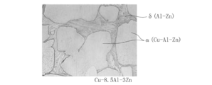
- FIG. 6 is an enlarged view of an Al—Cu—Zn alloy structure of a sintered bearing according to another embodiment. It is sectional drawing of a fuel pump. It is sectional drawing of an EGR valve.
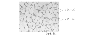
- FIG. 4 is an enlarged view of an Al—Cu alloy structure of a test piece according to a comparative example. It is a graph which shows the result of a corrosion test.
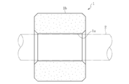
- the sintered bearing 1 according to one embodiment of the present invention has a cylindrical shape as shown in FIG. 1, and the shaft 2 is inserted into the inner periphery.
- the inner peripheral surface 1 a of the sintered bearing 1 is a cylindrical surface and functions as a bearing surface that slides and supports the outer peripheral surface of the shaft 2.
- the outer peripheral surface 1b of the sintered bearing 1 is a cylindrical surface and functions as an attachment surface attached to another member.
- the sintered bearing 1 is formed of a sintered metal, particularly an Al—Cu alloy-based sintered metal, and in this embodiment, is formed of a sintered metal containing Al, Cu, and Ni.
- the sintered bearing 1 includes, for example, 7 to 11% by mass of Al and 1 to 6% by mass of Ni, and the remaining main component is Cu.
- 3 to 6% by mass of graphite (free graphite) and 0.1 to 0.4% by mass of P are included with respect to 100% by mass of Al, Cu, and Ni in total.
- the sintered bearing 1 contains 8.5% by mass of Al and 5% by mass of Ni, and the remaining main component is Cu.
- the sintered bearing 1 has an Al—Cu—Ni alloy structure 3, and adjacent Al—Cu—Ni alloy structures 3 are sinter bonded. Innumerable internal voids 4 are provided between the Al—Cu—Ni alloy structures 3. The internal hole 4 communicates with the surface of the sintered bearing 1.
- An aluminum oxide coating 5 is formed on the surface of the Al—Cu—Ni alloy structure 3, that is, on the surface of the sintered bearing 1 including the inner peripheral surface 1 a (bearing surface) and around the internal holes 4 of the sintered bearing 1. Is formed. Since the Al—Cu—Ni alloy structure 3 is protected by the aluminum oxide film 5, the corrosion resistance and the wear resistance are improved.
- Free graphite 6 is distributed on the surface and inside of the sintered bearing 1. A part of this free graphite 6 is exposed on the bearing surface (inner peripheral surface 1a) of the sintered bearing 1. P (phosphorus) is present in the grain boundary portion of the Al—Cu—Ni alloy structure 3 (not shown).
- FIG. 3 shows the Al—Cu—Ni alloy structure 3 in an enlarged manner.
- the Al—Cu—Ni alloy structure 3 has an Al—Cu—Ni matrix phase ( ⁇ phase) and an Al—Ni compound phase ( ⁇ phase), while an Al—Cu compound phase. It does not have ( ⁇ phase).
- the composition of the Al—Cu—Ni alloy structure 3 (the combination of Al, Cu, Ni) is within the range where ⁇ phase and ⁇ phase are precipitated and ⁇ phase is not precipitated. Ratio) is set.
- the sintered bearing 1 can be provided with excellent corrosion resistance.
- the Al—Cu—Ni alloy structure 3 when the Al—Cu—Ni alloy structure 3 is formed on the sintered bearing 1, precipitation of a compound phase inferior in corrosion resistance is practically unavoidable, but the Al—Cu compound having particularly low corrosion resistance as described above. By precipitating the Al—Ni compound phase having a relatively high corrosion resistance without precipitating the phase, the corrosion resistance of the sintered bearing 1 can be further enhanced.
- the ratio of the Al—Cu—Ni matrix phase in the Al—Cu—Ni alloy structure 3 is preferably high.
- the area ratio is 50% or more, preferably 70% or more. It has become.
- the density ratio of the sintered bearing 1 is in the range of 80 to 95%. If the density ratio of the sintered bearing 1 is less than 80%, the strength is insufficient, and if the density ratio exceeds 95%, the oil content is insufficient, which is not preferable.
- the density ratio of the surface layer of the sintered bearing 1 is higher than the internal density ratio. That is, the porosity (surface aperture ratio) on the surface of the sintered bearing 1 is smaller than the porosity in the interior of the sintered bearing 1.
- the density ratio of the surface layer on the outer peripheral surface 1b side of the sintered bearing 1 is higher than the density ratio of the surface layer on the inner peripheral surface 1a side.
- the surface aperture ratio on the outer peripheral surface 1 b of the sintered bearing 1 is smaller than the surface aperture ratio on the inner peripheral surface 1 a of the sintered bearing 1.
- the internal holes of the sintered bearing 1 are impregnated with lubricating oil.
- lubricating oil mineral oil, polyalphaolefin (PAO), ester, liquid grease, and the like can be used.
- PAO polyalphaolefin
- ester organic compound
- liquid grease liquid grease
- the sintered bearing 1 includes a mixing step in which various powders are mixed to obtain a raw material powder, a green compacting step in which the raw material powder is compressed with a mold to obtain a green compact, and a green compact is sintered into a sintered body And a sizing process in which the sintered body is compressed and shaped with a mold.
- a mixing step in which various powders are mixed to obtain a raw material powder
- a green compacting step in which the raw material powder is compressed with a mold to obtain a green compact
- a green compact is sintered into a sintered body
- a sizing process in which the sintered body is compressed and shaped with a mold.
- raw material powder is generated by mixing various powders with a mixer.
- the raw material powder includes an Al source, a Cu source, a Ni source, a P source, and a powder that becomes a solid lubricant.
- the raw material powder does not include pure Cu powder or pure Al powder.
- the raw material powder is further mixed with a sintering aid (for example, aluminum fluoride powder or calcium fluoride powder) and a release lubricant (for example, zinc stearate powder or calcium stearate powder). Is done.
- a sintering aid for example, aluminum fluoride powder or calcium fluoride powder
- a release lubricant for example, zinc stearate powder or calcium stearate powder.
- Al and Cu sources for example, Al—Cu—Ni alloy powder or Al—Cu alloy powder can be used.
- Ni source for example, Al—Cu—Ni alloy powder or Cu—Ni alloy powder can be used.
- Al—Cu—Ni alloy powder pre-alloy powder
- the Al—Cu—Ni alloy powder contains 7 to 11% by mass of Al.
- the Al—Cu—Ni alloy powder for example, one produced by an atomizing method can be used.
- the particle diameter of the Al—Cu—Ni alloy powder is 106 ⁇ m or less, and the average particle diameter is 20 to 50 ⁇ m.
- the average particle size means an average value of particle sizes measured by laser diffraction. Specifically, the average value of the particle diameters when 5000 powders are measured by laser diffraction using SALD-3100 manufactured by Shimadzu Corporation (hereinafter the same).
- P alloy powder can be used as the P source.
- the P alloy powder for example, a P—Cu alloy powder can be used, and in this embodiment, 7 to 10 mass% P—Cu alloy powder was used.
- P has the effect of increasing the wettability between the solid and liquid phases during sintering. When there is too little P component, the sintering promotion effect between solid-liquid phases is scarce. On the other hand, when there are too many P components, sintering will advance too much and Al will segregate easily. Therefore, the compounding amount of the P alloy powder is, for example, 0.1 to 0.6% by mass, preferably 0.1 to 0.6% by mass with respect to 100% by mass of the total amount of Al, Cu and Ni in the P component in the raw material powder. It is set to be 0.4% by mass. *
- the solid lubricant for example, graphite powder can be used.
- the graphite powder is present as free graphite mainly in the pores and on the surface of the sintered bearing 1.
- the graphite powder exposed on the bearing surface (inner peripheral surface 1a) imparts excellent lubricity to the sintered bearing 1 and contributes to an improvement in wear resistance.
- the blending amount of the graphite powder is, for example, 3 to 6% by mass with respect to the total of 100% by mass of Al, Cu and Ni in the raw material powder. When the blending amount of graphite is less than 3% by mass, the effect of improving lubricity and wear resistance by adding graphite cannot be obtained.
- the amount of graphite exceeds 6% by mass, there is a concern that, for example, diffusion of Al into Cu starts to be inhibited. If the blending amount of graphite exceeds 10% by mass, the material strength is lowered and the diffusion of Al into Cu is hindered.
- the graphite powder used is a graphite powder having a particle size of 145 mesh or less, which is obtained by granulating natural graphite or artificial graphite fine powder with a resin binder.
- Aluminum fluoride and calcium fluoride function as a sintering aid. Specifically, aluminum fluoride and calcium fluoride gradually evaporate while melting at 850 to 900 ° C., which is the sintering temperature of the Al—Cu—Ni alloy powder, to protect the surface of the Al—Cu—Ni alloy powder. By suppressing the formation of aluminum oxide, sintering is promoted and aluminum diffusion is enhanced. Since aluminum fluoride and calcium fluoride evaporate and volatilize during sintering, the sintered bearing 1 is hardly left in the finished product. Aluminum fluoride and calcium fluoride are preferably added in a total amount of about 0.05 to 0.2 mass% with respect to a total of 100 mass% of Al, Cu, and Ni in the raw material powder.
- the effect as a sintering aid is insufficient, and a dense sintered body having high strength cannot be obtained.
- it exceeds 0.2% by mass the effect as a sintering aid will reach its peak even if it is added more, so it is preferable to keep it to 0.2% by mass or less from the viewpoint of cost.
- a sintering aid such as P alloy powder, aluminum fluoride and calcium fluoride, a solid lubricant such as graphite powder, and a release lubricant such as zinc stearate or Multiple types may not be blended into the raw material powder.
- the compacting step the above-mentioned raw material powder is filled in a compacting die and compressed to form a compact having substantially the same shape as the sintered bearing 1.
- the green compact is formed by compressing the raw material powder filled in the powder mold with a pressure of 200 to 700 MPa.
- the Al source is composed only of Al—Cu—Ni alloy powder, and the raw powder does not contain pure Al powder.
- the deterioration of the fluidity of the raw material powder due to the pure Al powder having a small specific gravity and the handling problems associated with the scattering of the pure Al particles are solved.
- the filling property of the raw material powder to a compacting die is improved, it is possible to avoid a decrease in moldability and insufficient strength of the compact.
- the green compact is heated at a predetermined sintering temperature to sinter-bond adjacent raw material powders to form a sintered body.
- the sintering step is performed using, for example, a mesh belt type continuous furnace.
- adjacent Al—Ni—Cu alloy powders Al—Cu—Ni alloy structure
- bonded bonded
- sintering of the Al—Cu—Ni alloy structures is promoted by the P component contained in the raw material powder, and the strength of the sintered body is increased.
- the graphite powder in the raw material powder remains as free graphite inside and on the surface of the sintered body.
- an Al—Cu—Ni matrix phase ( ⁇ phase) and an Al—Ni compound grain phase ( ⁇ phase) are precipitated.
- the Cu compound phase ( ⁇ phase) is not precipitated (see FIG. 2).
- an Al—Cu—Ni ternary phase diagram at the sintering temperature is acquired in advance, and the components and composition ratios for obtaining the above-described structure from the ternary phase diagram are set.
- a sintered body as described above can be obtained.
- the sintering temperature is preferably 900 to 950 ° C, more preferably 900 to 920 ° C.
- hydrogen gas, nitrogen gas, or these mixed gas can be used for atmospheric gas.
- the Al—Cu—Ni alloy powder generates various liquid phases when the eutectic temperature is 548 ° C. or higher.
- the liquid phase is generated, the green compact expands, and a sintered neck is formed by the generated liquid phase.
- the Al—Cu—Ni alloy structure is oxidized and the sintering is inhibited, so that the size remains expanded without being densified. Is concerned.
- the strength of the sintered body can be sufficiently secured.
- the sintered body expanded by the sintering is compressed and dimensioned.
- the core rod is inserted into the inner periphery of the sintered body, and these are integrally press-fitted into the inner periphery of the die in a state where the axial width of the sintered body is regulated to a predetermined dimension by the upper and lower punches.
- the outer peripheral surface of the sintered body is pressed by the die and molded, and the inner peripheral surface of the sintered body is pressed against the outer peripheral surface of the core rod and molded.
- the compression amount of the surface layer on the outer peripheral surface side of the sintered body is larger than the surface layer on the inner peripheral surface side, the density of the surface layer on the outer peripheral surface side becomes larger than the density on the inner peripheral surface side.
- the holes opened in the inner peripheral surface 1a may be further reduced by further rotating sizing the inner peripheral surface 1a of the sintered body.
- Oil impregnation process In the oil impregnation step, lubricating oil is impregnated in the internal pores of the sintered body. Specifically, after the sintered body is immersed in the lubricating oil under a reduced pressure environment, the internal pores of the sintered body are impregnated with the lubricating oil by returning to normal pressure. Thus, the sintered bearing 1 is completed.
- the composition of the sintered bearing 1 is not limited to the above, and Si may be blended in place of Ni in the above embodiment.
- the composition of the sintered bearing may include 7 to 11% by mass of Al, 1 to 6% by mass of Si, and the remaining main component may be Cu.
- FIG. 4 shows the Al—Cu—Si alloy structure of a sintered bearing containing 8.5% by mass of Al, 2% by mass of Si, and the remaining main component being Cu. In this Al—Cu—Si alloy structure, an Al—Cu—Si matrix phase ( ⁇ phase) and an Al—Si compound phase ( ⁇ phase) are precipitated, but an Al—Cu compound phase ( ⁇ phase). Is not precipitated.
- the ratio of the Al—Cu—Si matrix phase in the Al—Cu—Si alloy structure is, for example, 50% or more, preferably 70% or more in area ratio, and is approximately 75% in the illustrated example.
- Other components, production methods, and the like are the same as those in the above embodiment, and thus description thereof is omitted.
- the composition of the sintered bearing 1 may include 7 to 11% by mass of Al and 1 to 5% by mass (preferably 1 to 4% by mass) of Zn, with the remaining main component being Cu. it can.
- FIG. 5 shows an Al—Cu—Zn alloy structure of a sintered bearing containing 8.5% by mass of Al, 3% by mass of Zn, and the remaining main component being Cu.
- Al—Cu—Zn alloy structure an Al—Cu—Zn matrix phase ( ⁇ phase) and an Al—Zn compound phase ( ⁇ phase) are precipitated, but an Al—Cu compound phase ( ⁇ phase). Is not precipitated.
- the ratio of the Al—Cu—Zn matrix phase in the Al—Cu—Zn alloy structure is, for example, 50% or more, preferably 70% or more in area ratio, and is about 80% in the illustrated example.
- Other components, production methods, and the like are the same as those in the above embodiment, and thus description thereof is omitted.
- Si or Zn, or both of them may be blended. Moreover, it may replace with Ni of said embodiment and may mix
- the sintered bearing 1 is incorporated in, for example, a fuel pump (electric fuel pump 10) shown in FIG.
- the electric fuel pump 10 includes a substantially cylindrical metal housing 11, a synthetic resin motor cover 12 fixed to the upper end of the housing 11, and a metal pump cover 13 fixed to the lower end of the housing 11. And a pump body 14.
- a motor armature 15 is arranged inside the housing 11. Both ends in the axial direction of the shaft 2 provided in the armature 15 are rotatably supported by the sintered bearing 1 attached to the motor cover 12 and the pump cover 13. Lubricating oil is impregnated in the internal holes of the sintered bearing 1 in advance.
- a magnet 16 is fixed to the inner peripheral surface of the housing 11, and the magnet 16 and the armature 15 are opposed to each other in the radial direction at a predetermined interval.
- the motor cover 12 is provided with a discharge port 17 connected to a fuel supply pipe (not shown) that communicates with the fuel injection valve.
- the discharge port 17 is provided with a check valve 18 that prevents back flow of fuel.
- the check valve 18 is urged in the closing direction by a spring 19.
- the pump impeller 20 is fixed to the end portion (lower end in the figure) of the shaft 2. In the illustrated example, two pump impellers 20 are provided at two locations separated in the axial direction.
- the pump body 14 is provided with a suction port 21.
- the armature 15 and the 8-pump impeller 20 are integrally rotated, the fuel in the fuel tank is pumped up from the suction port 21, passes through the inside of the housing 11, and is discharged from the discharge port 17.
- the sintered bearing 1 that rotatably supports the shaft 2 of the armature 15 is in an environment that is always in contact with fuel (for example, gasoline).
- the sintered bearing 1 may be incorporated in the EGR valve 30 shown in FIG.
- the EGR valve 30 includes a housing 31, a valve 32 disposed inside the housing 31, a spring 33 that biases the valve 32 in a closing direction, and a drive unit 34 (for example, a step motor) that drives the valve 32 in an opening direction.
- a gas flow path 35 is formed inside the housing 31, and a valve seat 36 is provided in the middle of the gas flow path 35.
- a shaft 32 a of the valve 32 is supported by a sintered bearing 1 fixed to the housing 31 so as to be slidable in the axial direction.
- the sintered bearing 1 is used in a dry state, with no internal oil impregnated with lubricating oil.
- the valve 32 In the state where the drive unit 34 is stopped, the valve 32 is pressed against the valve seat 36 by the urging force of the spring 33, whereby the gas flow path 35 is closed. On the other hand, when the drive unit 34 is driven to move the valve 32 downward, the valve 32 is separated from the valve seat 36 and the gas flow path 35 is opened, and the exhaust gas discharged from the engine is moved to the intake side of the engine. Returned.
- test pieces (Examples 1 to 4 and Comparative Examples 1 to 4) made of sintered metals having different compositions were prepared and subjected to a corrosion test.
- Each test piece has the composition shown in Table 1 below, and is produced by the manufacturing method shown above. Hereinafter, each test piece will be described in detail.
- Al-Cu-Ni sintered body (Example 1, Example 2) It consists of a sintered body made by using a raw material powder containing Al—Cu—Ni alloy powder containing 7 to 11% by mass of Al, and 8.5% by mass of Al and 3.0% by mass of Ni (Example 1) Or 5.0 mass% (Example 2) is included, and the main component of the remainder is Cu.
- ⁇ phase precipitation of Al—Cu—Ni matrix phase
- Al—Ni compound phase ⁇ phase
- Al-Cu-Si sintered body (Example 3) It consists of a sintered body made using a raw material powder containing an Al—Cu—Si alloy powder containing 7 to 11% by mass of Al, containing 8.5% by mass of Al and 2.0% by mass of Si. The component is Cu.
- Al—Cu—Si alloy structure produced in this sintered body precipitation of Al—Cu—Si matrix phase ( ⁇ phase) and Al—Si compound phase ( ⁇ phase, ⁇ phase) was confirmed ( (See FIG. 4). Further, no precipitation of Al—Cu compound phase ( ⁇ phase) was confirmed.
- Al—Cu—Zn sintered body (Example 4, Comparative Example 1) A sintered body prepared using a raw material powder containing Al—Cu—Zn alloy powder containing 7 to 11% by mass of Al, and containing 8.5% by mass of Al and 3.0% by mass of Zn (Example 3) Or 5.0 mass% (comparative example 1) is included, and the main component of the remainder is Cu.
- the Al—Cu—Ni alloy structure formed in this sintered body precipitation of Al—Cu—Zn matrix phase ( ⁇ phase) and Al—Zn compound phase ( ⁇ phase) was confirmed (see FIG. 5). ). Further, no precipitation of Al—Cu compound phase ( ⁇ phase) was confirmed.
- Bronze sintered body (Comparative Example 2) It consists of a sintered body made using a raw material powder mainly containing Cu powder and Ni powder, and contains 30 to 35% by mass of Ni.
- Al-Cu sintered body (Comparative Example 3)
- the sintered body is made of a raw material powder containing Al—Cu alloy powder containing 7 to 11% by mass of Al, contains 8.5% by mass of Al, and the remaining main component is Cu.
- precipitation of Al—Cu matrix phase ( ⁇ phase) and Al—Cu compound phase ( ⁇ phase) was confirmed (see FIG. 8).
- Al-Cu-Sn sintered body (Comparative Example 4) It is composed of a sintered body prepared using a raw material powder containing Al-Cu alloy powder containing 7 to 11% by mass Al and Sn powder, and contains 8.5% by mass of Al and 3.0% by mass of Sn. The remaining main component is Cu. In the Al—Cu—Sn alloy structure produced in the sintered body, precipitation of Al—Cu—Zn matrix phase ( ⁇ phase) and Al—Cu compound phase ( ⁇ phase) was confirmed.
- the test pieces were immersed in a solution containing sulfide and organic acid for a predetermined time, and the weight change rate before and after immersion was measured.
- the weights of Examples 1 to 4 hardly changed before and after the immersion, whereas the weights of Comparative Examples 1 to 4 greatly changed before and after the immersion.
- the weights of Comparative Examples 1, 2, and 4 were significantly reduced by the above immersion treatment (Comparative Example 1: -45.13%, Comparative Example 2: -8.25%, Comparative Example 4:- 28.49%). This is presumably because the Al component in the sintered body was dissolved by the organic acid in the solution.
- the weight was significantly increased by the above immersion treatment (10.21%).
- Examples 1 to 4 in which an appropriate amount of Ni, Si, or Zn was added to a Cu—Al based sintered body had excellent corrosion resistance, and in particular, an Al—Cu—Ni alloy structure. It was confirmed that Examples 1 and 2 having a very high corrosion resistance.
Landscapes
- Engineering & Computer Science (AREA)
- General Engineering & Computer Science (AREA)
- Mechanical Engineering (AREA)
- Chemical & Material Sciences (AREA)
- Metallurgy (AREA)
- Materials Engineering (AREA)
- Organic Chemistry (AREA)
- Health & Medical Sciences (AREA)
- Toxicology (AREA)
- Combustion & Propulsion (AREA)
- Sliding-Contact Bearings (AREA)
- Powder Metallurgy (AREA)
Abstract
焼結軸受は、Al、Cu、及びNiを含み、Al-Cu-Ni合金組織3同士が焼結されている。Al-Cu-Ni合金組織3は、Al-Cu-Niマトリクス相(α相)及びAl-Ni化合物相(κ相)を有し、Al-Cu化合物相(γ相)を有さない。
Description
本発明は、焼結軸受に関し、特に、Al-Cu合金(アルミニウム青銅とも言われる。)系の焼結軸受に関する。
エンジンの燃料として用いられるガソリンや軽油等の品質は、世界の各地域で異なっており、粗悪な燃料(ガソリンや軽油等)やバイオ燃料等が使用されることもある。このような燃料と接触し得る箇所(例えば電動燃料ポンプやEGRバルブ)に設けられる軸受には、粗悪燃料やバイオ燃料に含まれる硫化物や有機酸に対する耐腐食性が求められる。
一方、エンジンの小型化及び軽量化に伴って、電動燃料ポンプ等にも小型化及び軽量化が求められ、これらに組み込まれる軸受にも小型化が求められる。例えば電動燃料ポンプでは、吐出性能を確保しつつ小型化を図るために、回転数を高める必要がある。このような高速回転する軸を支持する軸受には、小型化と共に耐腐食性、耐摩耗性(低摩擦特性)が要求される。
例えば、耐摩耗性に優れた軸受として、銅系焼結軸受が知られている。しかし、銅系焼結軸受は、粗悪燃料やバイオ燃料に含まれる硫化物や有機酸と接触することにより、銅が腐食されやすい。例えば、銅系焼結軸受に硫化物が接触すると、表面(特に軸受面)に硫化銅が生成することで、軸受面と軸との間の隙間が減少し、回転トルクの上昇を招く恐れがある。また、銅系焼結軸受に有機酸が接触すると、銅が溶出するため、耐摩耗性が低下して製品寿命が短くなる恐れがある。以上のように、銅系焼結軸受は、耐摩耗性には優れているが、耐腐食性に劣るため、粗悪燃料やバイオ燃料と接触する用途には向いていない。
例えば特許文献1には、Al-Cu合金系の焼結軸受が示されている。Al-Cu合金系の焼結軸受は、摺動性に優れると共に、表面に酸化アルミニウム膜が生成されるため耐腐食性にも優れている。
上記特許文献1には、Al-Cu合金系の焼結軸受の各成分の配合比を調整する技術が示されている。しかし、このような技術を適用しても、耐腐食性が十分に高められるとは言えず、さらなる検討が求められている
以上の事情に鑑み、本発明は、Al-Cu合金系の焼結軸受の耐腐食性を高めることを目的とする。
上記の目的を達成するために、本発明は、Al、Cu、及びNiを含み、Al-Cu-Ni合金組織同士が焼結された焼結軸受であって、前記Al-Cu-Ni合金組織は、Al-Cu-Niマトリクス相及びAl-Ni化合物相を有し、Al-Cu化合物相を有さない焼結軸受を提供する。
このように、Al-Cu合金系の焼結軸受にNiを配合し、合金組織にAl-Cu-Niマトリクス相(固溶体合金相)を析出させることで、耐腐食性が向上する。このとき、Al-Cu-Ni合金組織には、通常、マトリクス相だけでなく、マトリクス相よりも耐腐食性の低い化合物相が析出する。具体的に、Al-Cu化合物相は耐腐食性が特に低く、Al-Ni化合物相は、Al-Cu化合物相よりは耐腐食性が高い。従って、Al-Cu-Ni合金組織において、耐腐食性が特に劣るAl-Cu化合物相が析出せずに、耐腐食性が比較的優れたAl-Ni化合物相が析出するように、原料粉末の成分や配合比を調整すれば、非常に優れた耐腐食性を有する焼結軸受を得ることができる。
上記の焼結軸受の組成は、例えば、Alを7~11質量%、Niを1~6質量%含み、残部の主成分をCuとされる。
また、上記の焼結軸受において、Niの代わりにSiを配合しても、上記と同様の効果を得ることができる。すなわち、上記の目的は、Al、Cu、及びSiを含み、Al-Cu-Si合金組織同士が焼結された焼結軸受であって、前記Al-Cu-Si合金組織は、Al-Cu-Siマトリクス相及びAl-Si化合物相を有し、Al-Cu化合物相を有さない焼結軸受により達成することができる。この焼結軸受の組成は、例えば、Alを7~11質量%、Siを1~6質量%含み、残部の主成分をCuとされる。
さらに、上記の焼結軸受において、Niの代わりにZnを配合しても、上記と同様の効果を得ることができる。すなわち、上記の目的は、Al、Cu、及びZnを含み、Al-Cu-Zn合金組織同士が焼結された焼結軸受であって、前記Al-Cu-Zn合金組織は、Al-Cu-Znマトリクス相及びAl-Zn化合物相を有し、Al-Cu化合物相を有さない焼結軸受により達成することができる。この焼結軸受の組成は、例えば、Alを7~11質量%、Znを1~5質量%含み、残部の主成分をCuとされる。
ところで、純銅は硫化物が付着しやすいため、焼結軸受に純銅組織(Cu相)が存在すると、Cu相に硫化物が付着するため硫化腐食が生じやすい。このため、焼結軸受の原料に純銅粉末が含まれる場合は、Cu相にAlを拡散させて合金化する必要があり、焼結工程のコストが高くなる。従って、上記の焼結軸受の原料粉末は、純銅粉末を含まないことが好ましい。
上記のような焼結軸受の軸受面に遊離黒鉛を露出させると、遊離黒鉛の自己潤滑性により、潤滑性及び耐摩耗性を向上させることができる。
燃料ポンプに設けられた軸の回転を支持する軸受や、EGRバルブに設けられたバルブの軸方向の往復動を支持する軸受は、燃料等に含まれる硫化物や有機酸と接触し、優れた耐腐食性が求められる。このような用途で使用される軸受として、上記の焼結軸受が好適に使用できる。
以上のように、本発明によれば、Al-Cu合金系の焼結軸受の耐腐食性を高めることができる。
本発明の一実施形態に係る焼結軸受1は、図1に示すように円筒状を成し、内周に軸2が挿入される。焼結軸受1の内周面1aは円筒面であり、軸2の外周面を摺動支持する軸受面として機能する。焼結軸受1の外周面1bは円筒面であり、他部材に取り付けられる取付面として機能する。
焼結軸受1は、焼結金属、特にAl-Cu合金系の焼結金属で形成され、本実施形態では、Al,Cu,及びNiを含む焼結金属で形成される。具体的に、焼結軸受1は、例えば、Alを7~11質量%、Niを1~6質量%含み、残部の主成分がCuとされる。本実施形態では、上記の他、Al、Cu、Niの合計100質量%に対し、3~6質量%の黒鉛(遊離黒鉛)と、0.1~0.4質量%のPを含む。本実施形態では、焼結軸受1が、Alを8.5質量%、Niを5質量%含み、残部の主成分がCuとされる。
焼結軸受1は、図2に拡大して示すように、Al-Cu-Ni合金組織3を有し、隣接するAl-Cu-Ni合金組織3同士が焼結結合されている。Al-Cu-Ni合金組織3の間には、無数の内部空孔4が設けられる。内部空孔4は、焼結軸受1の表面に連通している。Al-Cu-Ni合金組織3の表面、すなわち、内周面1a(軸受面)を含む焼結軸受1の表面や、焼結軸受1の内部空孔4の周りには、酸化アルミニウム被膜5が形成されている。この酸化アルミニウム被膜5によりAl-Cu-Ni合金組織3が保護されるため、耐腐食性及び耐摩耗性が高められる。焼結軸受1の表面及び内部には遊離黒鉛6が分布している。この遊離黒鉛6の一部が、焼結軸受1の軸受面(内周面1a)に露出している。Al-Cu-Ni合金組織3の粒界部には、P(燐)が存在している(図示省略)。
図3に、Al-Cu-Ni合金組織3をさらに拡大して示す。同図に示すように、Al-Cu-Ni合金組織3は、Al-Cu-Niマトリクス相(α相)と、Al-Ni化合物相(κ相)とを有する一方で、Al-Cu化合物相(γ相)は有していない。換言すると、Al-Cu-Ni三元状態図において、α相及びκ相が析出し、且つγ相が析出しない範囲で、Al-Cu-Ni合金組織3の組成(Al,Cu,Niの配合比)が設定される。このように、耐腐食性が非常に高いAl-Cu-Niマトリクス相を析出させることで、焼結軸受1に優れた耐腐食性を付与することができる。また、焼結軸受1にAl-Cu-Ni合金組織3を生成する際、耐食性に劣る化合物相の析出は現実的に避けられないが、上記のように耐腐食性が特に低いAl-Cu化合物相を析出させずに、耐腐食性が比較的高いAl-Ni化合物相を析出させることで、焼結軸受1の耐腐食性がさらに高められる。このとき、Al-Cu-Ni合金組織3におけるAl-Cu-Niマトリクス相の割合は高い方が好ましく、例えば面積比で50%以上、好ましくは70%以上とされ、図示例ではおよそ85%程度となっている。
焼結軸受1の密度比は、80~95%の範囲とされる。焼結軸受1の密度比が80%未満では強度が不十分となり、密度比が95%を超えると含油量が不足するため、好ましくない。焼結軸受1の表層の密度比は、内部の密度比よりも高くなっている。すなわち、焼結軸受1の表面における空孔率(表面開口率)が、焼結軸受1の内部における空孔率よりも小さくなっている。また、焼結軸受1の外周面1b側の表層の密度比は、内周面1a側の表層の密度比よりも高くなっている。すなわち、焼結軸受1の外周面1bにおける表面開口率が、焼結軸受1の内周面1aにおける表面開口率よりも小さくなっている。尚、密度比αは次式で表される。
α(%)=(ρ1/ρ0)×100
ただし、ρ1:多孔質体の密度、ρ0:その多孔質体に空孔がないと仮定した場合の密度
また、焼結軸受1の表層とは、焼結軸受1の表面から所定の深さ(例えば、焼結軸受1の内径の1/100~1/15程度の深さ)までの領域とする。
α(%)=(ρ1/ρ0)×100
ただし、ρ1:多孔質体の密度、ρ0:その多孔質体に空孔がないと仮定した場合の密度
また、焼結軸受1の表層とは、焼結軸受1の表面から所定の深さ(例えば、焼結軸受1の内径の1/100~1/15程度の深さ)までの領域とする。
焼結軸受1の内部空孔には、潤滑油が含浸されている。潤滑油としては鉱油、ポリαオレフィン(PAO)、エステル、液状グリース等を使用することができる。ただし、軸受の用途によっては必ずしも潤滑油を含浸する必要はなく、ドライ状態で使用してもよい。
焼結軸受1の内周に挿入された軸2が回転又は軸方向移動、あるいはこれらの双方の運動をし、焼結軸受1の内周面1aと軸2の外周面が摺動すると、焼結軸受1の内部空孔に保持された潤滑油が温度上昇に伴って内周面1aに滲み出す。この内周面1aに滲み出した潤滑油によって、焼結軸受1の内周面1aと軸2の外周面との間の軸受隙間に油膜が形成され、軸2が焼結軸受1によって支持される。
次に、上記の焼結軸受1の製造方法を説明する。
焼結軸受1は、各種粉末を混合して原料粉末を得る混合工程と、原料粉末を金型で圧縮して圧粉体を得る圧粉工程と、圧粉体を焼結して焼結体を得る焼結工程と、焼結体を金型で圧縮して整形するサイジング工程とを経て形成される。以下、各工程を詳しく説明する。
[混合工程]
混合工程では、各種粉末を混合機で混合することで、原料粉末が生成される。原料粉末は、Al源、Cu源、Ni源、P源、及び固体潤滑剤となる粉末を含む。原料粉末には、純Cu粉末や純Al粉末は含まれない。原料粉末には、必要に応じて、さらに、焼結助剤(例えば、フッ化アルミニウム粉末やフッ化カルシウム粉末)や、離型用潤滑剤(例えば、ステアリン酸亜鉛粉末やステアリン酸カルシウム粉末)が混合される。以下、各粉末について詳しく説明する。
混合工程では、各種粉末を混合機で混合することで、原料粉末が生成される。原料粉末は、Al源、Cu源、Ni源、P源、及び固体潤滑剤となる粉末を含む。原料粉末には、純Cu粉末や純Al粉末は含まれない。原料粉末には、必要に応じて、さらに、焼結助剤(例えば、フッ化アルミニウム粉末やフッ化カルシウム粉末)や、離型用潤滑剤(例えば、ステアリン酸亜鉛粉末やステアリン酸カルシウム粉末)が混合される。以下、各粉末について詳しく説明する。
Al及びCu源としては、例えばAl-Cu-Ni合金粉末やAl-Cu合金粉末を使用できる。Ni源としては、例えばAl-Cu-Ni合金粉末やCu-Ni合金粉末を使用できる。本実施形態では、Al、Cu、Ni源として、Al-Cu-Ni合金粉末(プレアロイ粉末)が用いられる。Al-Cu-Ni合金粉末は、7~11質量%のAlを含む。Al-Cu-Ni合金粉末は、例えばアトマイズ法により製造したものが使用できる。Al-Cu-Ni合金粉末の粒径は106μm以下で、平均粒径は20~50μmである。尚、平均粒径とは、レーザ回折により測定した粒径の平均値を意味する。具体的には、(株)島津製作所製SALD-3100により、5000粉末をレーザ回折で測定したときの粒径の平均値とする(以下同様)。
P源としては、P合金粉末を使用できる。P合金粉末は、例えばP-Cu合金粉末を使用することができ、本実施形態では7~10質量%P-Cu合金粉末を用いた。Pは、焼結時の固液相間の濡れ性を高める効果がある。P成分が少なすぎると、固液相間の焼結促進効果が乏しい。一方、P成分が多すぎると、焼結が進み過ぎてAlが偏析しやすくなる。従って、P合金粉末の配合量は、例えば、原料粉末中のP成分が、Al、Cu、及びNiの合計100質量%に対して0.1~0.6質量%、好ましくは0.1~0.4質量%となるように設定される。
固体潤滑剤としては、例えば黒鉛粉末を使用できる。黒鉛粉末は、主として焼結軸受1の空孔内や表面に遊離黒鉛として存在する。特に、軸受面(内周面1a)に露出した黒鉛粉末は、焼結軸受1に優れた潤滑性を付与し、耐摩耗性の向上に寄与する。黒鉛粉末の配合量は、例えば、原料粉末中のAl、Cu、Niの合計100質量%に対して、3~6質量%とされる。黒鉛の配合量が3質量%未満では、黒鉛添加による潤滑性、耐摩耗性の向上効果が得られない。一方、黒鉛の配合量が6質量%を超えると、例えばAlのCuへの拡散が阻害され始めることが懸念される。黒鉛の配合量が10質量%を超えると、材料強度が低下し、AlのCuへの拡散を阻害するので好ましくない。尚、一般的には、原料粉末の主成分に対して黒鉛を4質量%以上添加すると成形することが困難となるが、黒鉛粉末として造粒黒鉛を使用することで、成形が可能となる。本実施形態では、黒鉛粉末は、天然黒鉛又は人造黒鉛の微粉を樹脂バインダで造粒後粉砕し、粒径145メッシュ以下の黒鉛粉末を用いた。
フッ化アルミニウム及びフッ化カルシウムは、焼結助剤として機能する。具体的に、フッ化アルミニウム及びフッ化カルシウムは、Al-Cu-Ni合金粉末の焼結温度である850~900℃で溶融しながら徐々に蒸発し、Al-Cu-Ni合金粉末の表面を保護して酸化アルミニウムの生成を抑制することにより、焼結を促進しアルミニウムの拡散を増進させる。フッ化アルミニウム及びフッ化カルシウムは、焼結時に蒸発、揮散するので、焼結軸受1の完成品には殆ど残らない。フッ化アルミニウム及びフッ化カルシウムは、原料粉末中のAl、Cu、Niの合計100質量%に対して、合計で0.05~0.2質量%程度で添加することが好ましい。0.05質量%未満では、焼結助剤としての効果が不十分となり、緻密で高強度を有する焼結体が得られない。一方、0.2質量%を超えると、それ以上添加しても焼結助剤としての効果は頭打ちとなるため、コスト的な観点から0.2質量%以下に止めることが好ましい。
尚、特に必要がなければ、P合金粉末、フッ化アルミニウム及びフッ化カルシウム等の焼結助剤、黒鉛粉末等の固体潤滑剤、及びステアリン酸亜鉛等の離型用潤滑剤のうちの一種又は複数種を、原料粉末に配合しなくてもよい。
[圧粉工程]
圧粉工程では、上記の原料粉末を圧粉金型に充填して圧縮することにより、焼結軸受1と略同じ形状をなした圧粉体を形成する。本実施形態では、圧粉金型に充填した原料粉末を200~700MPaの加圧力で圧縮することにより圧粉体を成形する。尚、圧粉金型を70℃以上に加温した状態で、圧粉体を成形してもよい。
圧粉工程では、上記の原料粉末を圧粉金型に充填して圧縮することにより、焼結軸受1と略同じ形状をなした圧粉体を形成する。本実施形態では、圧粉金型に充填した原料粉末を200~700MPaの加圧力で圧縮することにより圧粉体を成形する。尚、圧粉金型を70℃以上に加温した状態で、圧粉体を成形してもよい。
本実施形態の焼結軸受1では、Al源がAl-Cu-Ni合金粉末のみで構成されており、原料粉末に純Al粉末は含まれない。これにより、比重の小さい純Al粉末に起因した原料粉末の流動性の悪化や、純Al粒子の飛散に伴う取り扱い上の問題が解消される。これにより、圧粉金型への原料粉末の充填性が高められるため、成形性の低下や圧粉体の強度不足を回避できる。
[焼結工程]
焼結工程では、圧粉体を所定の焼結温度で加熱し、隣接する原料粉末同士を焼結結合させることによって焼結体を形成する。焼結工程は、例えば、メッシュベルト式連続炉を用いて行われる。圧粉体を加熱することで、隣接するAl-Ni-Cu合金粉末(Al-Cu-Ni合金組織)同士が焼結結合(拡散接合)し、焼結体が形成される。このとき、原料粉末に含まれるP成分により、Al-Cu-Ni合金組織同士の焼結が促進され、焼結体の強度が高められる。また、原料粉末中の黒鉛粉末は、焼結体の内部及び表面に遊離黒鉛として残存する。
焼結工程では、圧粉体を所定の焼結温度で加熱し、隣接する原料粉末同士を焼結結合させることによって焼結体を形成する。焼結工程は、例えば、メッシュベルト式連続炉を用いて行われる。圧粉体を加熱することで、隣接するAl-Ni-Cu合金粉末(Al-Cu-Ni合金組織)同士が焼結結合(拡散接合)し、焼結体が形成される。このとき、原料粉末に含まれるP成分により、Al-Cu-Ni合金組織同士の焼結が促進され、焼結体の強度が高められる。また、原料粉末中の黒鉛粉末は、焼結体の内部及び表面に遊離黒鉛として残存する。
こうして得られた焼結体のAl-Cu-Ni合金組織には、Al-Cu-Niマトリクス相(α相)とAl-Ni化合粒相(κ相)とが析出している一方で、Al-Cu化合物相(γ相)は析出していない(図2参照)。このような合金組織が得られるように、原料粉末の成分や配合比を設定することで、非常に優れた耐腐食性が得られる。具体的には、例えば、予め当該焼結温度におけるAl-Cu-Niの三元状態図を取得し、この三元状態図から上記のような組織が得られる成分及びその配合比を設定することで、上記のような焼結体を得ることができる。
焼結温度は900~950℃が好ましく、900~920℃がさらに好ましい。また、雰囲気ガスは、水素ガス、窒素ガスあるいはこれらの混合ガスを使用できる。焼結時間は、長くするほど耐腐食性が向上し、例えば燃料ポンプに用いられる焼結軸受1では20~60分(例えば30分)が好ましい。
Al-Cu-Ni合金粉末は、共晶温度548℃以上になると様々な液相が発生する。液相が発生すると圧粉体が膨張し、発生した液相により焼結ネックが形成された後、緻密化に至って収縮することで焼結体が得られる。このとき、焼結体の表層では、Al-Cu-Ni合金組織が酸化されて焼結が阻害されることにより、緻密化に至らず寸法が膨張したままとなるため、焼結体の強度不足が懸念される。しかし、焼結体の内部では、Al-Cu-Ni合金組織は酸化されにくく、十分に焼結されるため、焼結体の強度を十分確保することができる。
[サイジング工程]
サイジング工程では、焼結により膨張した焼結体を圧縮して寸法整形する。具体的には、焼結体の内周にコアロッドを挿入すると共に、上下パンチで焼結体の軸方向幅を所定寸法に規定した状態で、これらを一体的にダイの内周に圧入する。これにより、焼結体の外周面がダイで圧迫されて成形されると共に、焼結体の内周面がコアロッドの外周面に押し付けられて成形される。このサイジング工程により、膨張した焼結体の表層が圧縮され、表層の密度が内部の密度よりも大きくなる。また、焼結体の外周面側の表層は、内周面側の表層よりも圧縮量が大きくなるため、外周面側の表層の密度が内周面側の密度よりも大きくなる。尚、サイジング工程の後、焼結体の内周面1aにさらに回転サイジングすることで、内周面1a(軸受面)に開口した空孔をさらに小さくしてもよい。
サイジング工程では、焼結により膨張した焼結体を圧縮して寸法整形する。具体的には、焼結体の内周にコアロッドを挿入すると共に、上下パンチで焼結体の軸方向幅を所定寸法に規定した状態で、これらを一体的にダイの内周に圧入する。これにより、焼結体の外周面がダイで圧迫されて成形されると共に、焼結体の内周面がコアロッドの外周面に押し付けられて成形される。このサイジング工程により、膨張した焼結体の表層が圧縮され、表層の密度が内部の密度よりも大きくなる。また、焼結体の外周面側の表層は、内周面側の表層よりも圧縮量が大きくなるため、外周面側の表層の密度が内周面側の密度よりも大きくなる。尚、サイジング工程の後、焼結体の内周面1aにさらに回転サイジングすることで、内周面1a(軸受面)に開口した空孔をさらに小さくしてもよい。
[含油工程]
含油工程では、上記の焼結体の内部空孔に潤滑油が含浸される。具体的には、減圧環境下で焼結体を潤滑油中に浸漬した後、常圧に戻すことで、焼結体の内部空孔に潤滑油が含浸される。以上により、焼結軸受1が完成する。
含油工程では、上記の焼結体の内部空孔に潤滑油が含浸される。具体的には、減圧環境下で焼結体を潤滑油中に浸漬した後、常圧に戻すことで、焼結体の内部空孔に潤滑油が含浸される。以上により、焼結軸受1が完成する。
本発明は上記の実施形態に限られない。例えば、焼結軸受1の組成は上記に限らず、上記の実施形態のNiに代えて、Siを配合してもよい。具体的には、例えば焼結軸受の組成を、Alを7~11質量%、Siを1~6質量%含み、残部の主成分をCuとすることができる。図4に、Alを8.5質量%、Siを2質量%含み、残部の主成分をCuとした焼結軸受のAl-Cu-Si合金組織を示す。このAl-Cu-Si合金組織には、Al-Cu-Siマトリクス相(α相)と、Al-Si化合物相(κ相)とが析出しているが、Al-Cu化合物相(γ相)は析出していない。Al-Cu-Si合金組織におけるAl-Cu-Siマトリクス相の割合は、例えば面積比で50%以上、好ましくは70%以上とされ、図示例ではおよそ75%程度となっている。その他の成分や製法等は、上記の実施形態と同様であるため、説明を省略する。
また、上記の実施形態のNiに代えて、Znを配合してもよい。具体的には、例えば焼結軸受1の組成を、Alを7~11質量%、Znを1~5質量%(好ましくは1~4質量%)含み、残部の主成分をCuとすることができる。図5に、Alを8.5質量%、Znを3質量%含み、残部の主成分をCuとした焼結軸受のAl-Cu-Zn合金組織を有する。このAl-Cu-Zn合金組織には、Al-Cu-Znマトリクス相(α相)と、Al-Zn化合物相(δ相)とが析出しているが、Al-Cu化合物相(γ相)は析出していない。Al-Cu-Zn合金組織におけるAl-Cu-Znマトリクス相の割合は、例えば面積比で50%以上、好ましくは70%以上とされ、図示例ではおよそ80%程度となっている。その他の成分や製法等は、上記の実施形態と同様であるため、説明を省略する。
また、上記の実施形態のNiに加えて、Si又はZn、あるいはこれらの双方を配合してもよい。また、上記の実施形態のNiに代えて、Si及びZnを配合してもよい。
上記の焼結軸受1は、例えば、図6に示す燃料ポンプ(電動燃料ポンプ10)に組み込まれる。電動燃料ポンプ10は、略円筒状の金属製のハウジング11と、ハウジング11の上端部に固定された合成樹脂製のモータカバー12と、ハウジング11の下端部に固定された金属製のポンプカバー13及びポンプボデー14とを有する。
ハウジング11の内部には、モータのアーマチュア15が配置されている。アーマチュア15に設けられた軸2の軸方向両端部は、モータカバー12とポンプカバー13に取り付けられた焼結軸受1により回転自在に支持されている。焼結軸受1の内部空孔には、予め潤滑油が含浸されている。ハウジング11に内周面にはマグネット16が固定され、このマグネット16とアーマチュア15とが所定間隔で半径方向に対向している。モータカバー12には、燃料噴射弁に通じる燃料供給パイプ(図示省略)に接続される吐出口17が設けられている。この吐出口17には、燃料の逆流を阻止するチェックバルブ18が設けられる。チェックバルブ18は、スプリング19により閉止方向に付勢されている。
軸2の端部(図中下端)には、ポンプインペラ20が固定される。図示例では、2つのポンプインペラ20が軸方向に離隔した2箇所に設けられる。ポンプボデー14には吸入口21が設けられている。アーマチュア15及び8ポンプインペラ20を一体回転させると、燃料タンク内の燃料が吸入口21より汲み上げられ、ハウジング11の内部を通過して、吐出口17から吐出される。アーマチュア15の軸2を回転自在に支持する焼結軸受1は、燃料(例えば、ガソリン)と常に接触する環境下にある。
また、上記の焼結軸受1は、図7に示すEGRバルブ30に組み込んでもよい。EGRバルブ30は、ハウジング31と、ハウジング31の内部に配されたバルブ32と、バルブ32を閉じる方向に付勢するスプリング33と、バルブ32を開く方向に駆動する駆動部34(例えばステップモータ)とを備える。ハウジング31の内部にはガス流路35が形成され、ガス流路35の途中に弁座36が設けられる。バルブ32のシャフト32aは、ハウジング31に固定された焼結軸受1により軸方向に摺動自在に支持されている。この焼結軸受1は、内部空孔に潤滑油が含浸されておらず、ドライ状態で使用される。
駆動部34を停止した状態では、バルブ32がスプリング33の付勢力により弁座36に押し付けられ、これによりガス流路35が閉じた状態となる。一方、駆動部34を駆動してバルブ32を下方に移動させると、バルブ32が弁座36から離反してガス流路35が開いた状態となり、エンジンから排出された排ガスがエンジンの吸気側に戻される。
次に、組成の異なる焼結金属からなる複数の試験片(実施例1~4、比較例1~4)を作製し、これらに対して腐食試験を施した。各試験片は、下記の表1に示す組成を有し、上記に示した製法で作製されたものである。以下、各試験片について詳しく説明する。

Al-Cu-Ni系焼結体(実施例1、実施例2)
7~11質量%Alを含むAl-Cu-Ni合金粉を含む原料粉末を用いて作成した焼結体からなり、Alを8.5質量%、Niを3.0質量%(実施例1)あるいは5.0質量%(実施例2)含み、残部の主成分がCuである。この焼結体に生成されたAl-Cu-Ni合金組織には、Al-Cu-Niマトリクス相(α相)と、Al-Ni化合物相(κ相)の析出が確認された(図3参照)。また、Al-Cu化合物相(γ相)の析出は確認されなかった。
7~11質量%Alを含むAl-Cu-Ni合金粉を含む原料粉末を用いて作成した焼結体からなり、Alを8.5質量%、Niを3.0質量%(実施例1)あるいは5.0質量%(実施例2)含み、残部の主成分がCuである。この焼結体に生成されたAl-Cu-Ni合金組織には、Al-Cu-Niマトリクス相(α相)と、Al-Ni化合物相(κ相)の析出が確認された(図3参照)。また、Al-Cu化合物相(γ相)の析出は確認されなかった。
Al-Cu-Si系焼結体(実施例3)
7~11質量%Alを含むAl-Cu-Si合金粉を含む原料粉末を用いて作成した焼結体からなり、Alを8.5質量%、Siを2.0質量%含み、残部の主成分がCuである。この焼結体に生成されたAl-Cu-Si合金組織には、Al-Cu-Siマトリクス相(α相)と、Al-Si化合物相(δ相,κ相)の析出が確認された(図4参照)。また、Al-Cu化合物相(γ相)の析出は確認されなかった。
7~11質量%Alを含むAl-Cu-Si合金粉を含む原料粉末を用いて作成した焼結体からなり、Alを8.5質量%、Siを2.0質量%含み、残部の主成分がCuである。この焼結体に生成されたAl-Cu-Si合金組織には、Al-Cu-Siマトリクス相(α相)と、Al-Si化合物相(δ相,κ相)の析出が確認された(図4参照)。また、Al-Cu化合物相(γ相)の析出は確認されなかった。
Al-Cu-Zn系焼結体(実施例4、比較例1)
7~11質量%Alを含むAl-Cu-Zn合金粉を含む原料粉末を用いて作成した焼結体からなり、Alを8.5質量%、Znを3.0質量%(実施例3)あるいは5.0質量%(比較例1)含み、残部の主成分がCuである。この焼結体に生成されたAl-Cu-Ni合金組織には、Al-Cu-Znマトリクス相(α相)と、Al-Zn化合物相(δ相)の析出が確認された(図5参照)。また、Al-Cu化合物相(γ相)の析出は確認されなかった。
7~11質量%Alを含むAl-Cu-Zn合金粉を含む原料粉末を用いて作成した焼結体からなり、Alを8.5質量%、Znを3.0質量%(実施例3)あるいは5.0質量%(比較例1)含み、残部の主成分がCuである。この焼結体に生成されたAl-Cu-Ni合金組織には、Al-Cu-Znマトリクス相(α相)と、Al-Zn化合物相(δ相)の析出が確認された(図5参照)。また、Al-Cu化合物相(γ相)の析出は確認されなかった。
白銅系焼結体(比較例2)
Cu粉末及びNi粉末を主に含む原料粉末を用いて作成した焼結体からなり、Niを30~35質量%含む。
Cu粉末及びNi粉末を主に含む原料粉末を用いて作成した焼結体からなり、Niを30~35質量%含む。
Al-Cu系焼結体(比較例3)
7~11質量%Alを含むAl-Cu合金粉を含む原料粉末を用いて作成した焼結体からなり、Alを8.5質量%含み、残部の主成分がCuである。この焼結体に生成されたAl-Cu合金組織には、Al-Cuマトリクス相(α相)とAl-Cu化合物相(γ相)の析出が確認された(図8参照)。
7~11質量%Alを含むAl-Cu合金粉を含む原料粉末を用いて作成した焼結体からなり、Alを8.5質量%含み、残部の主成分がCuである。この焼結体に生成されたAl-Cu合金組織には、Al-Cuマトリクス相(α相)とAl-Cu化合物相(γ相)の析出が確認された(図8参照)。
Al-Cu-Sn系焼結体(比較例4)
7~11質量%Alを含むAl-Cu合金粉と、Sn粉末とを含む原料粉末を用いて作成した焼結体からなり、Alを8.5質量%、Snを3.0質量%含み、残部の主成分がCuである。この焼結体に生成されたAl-Cu-Sn合金組織には、Al-Cu-Znマトリクス相(α相)とAl-Cu化合物相(γ相)の析出が確認された。
7~11質量%Alを含むAl-Cu合金粉と、Sn粉末とを含む原料粉末を用いて作成した焼結体からなり、Alを8.5質量%、Snを3.0質量%含み、残部の主成分がCuである。この焼結体に生成されたAl-Cu-Sn合金組織には、Al-Cu-Znマトリクス相(α相)とAl-Cu化合物相(γ相)の析出が確認された。
上記各試験片を、硫化物及び有機酸を含む溶液中に所定時間浸漬し、浸漬前後の重量変化率を測定した。その結果、図9に示すように、実施例1~4は、浸漬前後で重量がほとんど変化しなかったのに対し、比較例1~4は浸漬前後で重量が大きく変化した。具体的に、比較例1、2、4は、上記の浸漬処理により重量が大幅に減少した(比較例1:-45.13%、比較例2:-8.25%、比較例4:-28.49%)。これは、溶液中の有機酸により、焼結体中のAl成分が溶け出したためと考えられる。また、比較例3は、上記の浸漬処理により重量が大幅に増大した(+10.21%)。これは、焼結体に硫化物が付着したためと考えられる。これに対し、実施例1~4は、何れも上記の浸漬処理による重量変化率がごく僅か(およそ0.5%未満)に抑えられた。これらの結果から、Cu-Al系焼結体に、Ni、Si、Znの何れかを適量添加した実施例1~4は優れた耐腐食性を有し、特に、Al-Cu-Ni合金組織を有する実施例1及び2が非常に優れた耐腐食性を有することが確認された。
1 焼結軸受
2 軸
3 Al-Cu-Ni合金組織
4 内部空孔
5 酸化アルミニウム被膜
6 遊離黒鉛
10 電動燃料ポンプ
30 EGRバルブ
2 軸
3 Al-Cu-Ni合金組織
4 内部空孔
5 酸化アルミニウム被膜
6 遊離黒鉛
10 電動燃料ポンプ
30 EGRバルブ
Claims (10)
- Al、Cu、及びNiを含み、Al-Cu-Ni合金組織同士が焼結された焼結軸受であって、
前記Al-Cu-Ni合金組織は、Al-Cu-Niマトリクス相及びAl-Ni化合物相を有し、Al-Cu化合物相を有さない焼結軸受。 - Alを7~11質量%、Niを1~6質量%含み、残部の主成分をCuとした請求項1記載の焼結軸受。
- Al、Cu、及びSiを含み、Al-Cu-Si合金組織同士が焼結された焼結軸受であって、
前記Al-Cu-Si合金組織は、Al-Cu-Siマトリクス相及びAl-Si化合物相を有し、Al-Cu化合物相を有さない焼結軸受。 - Alを7~11質量%、Siを1~6質量%含み、残部の主成分をCuとした請求項3記載の焼結軸受。
- Al、Cu、及びZnを含み、Al-Cu-Zn合金組織同士が焼結された焼結軸受であって、
前記Al-Cu-Zn合金組織には、Al-Cu-Znマトリクス相及びAl-Zn化合物相を有し、Al-Cu化合物相を有さない焼結軸受。 - Alを7~11質量%、Znを1~5質量%含み、残部の主成分をCuとした請求項5記載の焼結軸受。
- 原料粉末が純銅粉末を含まない請求項1~6の何れかに記載の焼結軸受。
- 軸受面に遊離黒鉛を露出させた請求項1~7の何れかに記載の焼結軸受。
- 請求項1~8の何れかに記載の焼結軸受と、前記焼結軸受の内周に挿入され、回転自在に支持される軸と、前記軸に固定されたポンプインペラとを備えた燃料ポンプ。
- 請求項1~8の何れかに記載の焼結軸受と、前記焼結軸受の内周に挿入され、軸方向移動自在に支持される軸を有するバルブとを備えたEGRバルブ。
Priority Applications (3)
| Application Number | Priority Date | Filing Date | Title |
|---|---|---|---|
| DE112015005771.4T DE112015005771T5 (de) | 2014-12-26 | 2015-12-01 | Gesintertes Lager |
| CN201580068407.0A CN107000062B (zh) | 2014-12-26 | 2015-12-01 | 烧结轴承 |
| US15/533,738 US10697494B2 (en) | 2014-12-26 | 2015-12-01 | Sintered bearing |
Applications Claiming Priority (2)
| Application Number | Priority Date | Filing Date | Title |
|---|---|---|---|
| JP2014-265247 | 2014-12-26 | ||
| JP2014265247A JP6523682B2 (ja) | 2014-12-26 | 2014-12-26 | 焼結軸受 |
Publications (1)
| Publication Number | Publication Date |
|---|---|
| WO2016104067A1 true WO2016104067A1 (ja) | 2016-06-30 |
Family
ID=56150099
Family Applications (1)
| Application Number | Title | Priority Date | Filing Date |
|---|---|---|---|
| PCT/JP2015/083685 Ceased WO2016104067A1 (ja) | 2014-12-26 | 2015-12-01 | 焼結軸受 |
Country Status (5)
| Country | Link |
|---|---|
| US (1) | US10697494B2 (ja) |
| JP (1) | JP6523682B2 (ja) |
| CN (1) | CN107000062B (ja) |
| DE (1) | DE112015005771T5 (ja) |
| WO (1) | WO2016104067A1 (ja) |
Cited By (1)
| Publication number | Priority date | Publication date | Assignee | Title |
|---|---|---|---|---|
| CN114833341A (zh) * | 2022-05-07 | 2022-08-02 | 成都惠灵丰金刚石钻头有限公司 | 金刚石轴承烧结工艺 |
Families Citing this family (4)
| Publication number | Priority date | Publication date | Assignee | Title |
|---|---|---|---|---|
| JP2019100360A (ja) * | 2017-11-28 | 2019-06-24 | マブチモーター株式会社 | 油軸受、その製造方法、及び、モータ組立体 |
| ES2926178T3 (es) * | 2018-04-20 | 2022-10-24 | Valmet Flow Control Oy | Válvula y método de fabricación de una superficie de apoyo para una válvula |
| DE112020006054T5 (de) | 2019-12-11 | 2022-12-29 | Diamet Corporation | Verfahren zur Herstellung einer Cu-Ni-Al-basierten Sinterlegierung |
| DE102020106240A1 (de) | 2020-03-09 | 2021-09-09 | Bayerische Motoren Werke Aktiengesellschaft | Abgasrückführungsvorrichtung für eine Verbrennungskraftmaschine und Verbrennungskraftmaschine für ein Kraftfahrzeug |
Citations (5)
| Publication number | Priority date | Publication date | Assignee | Title |
|---|---|---|---|---|
| JPH04131339A (ja) * | 1990-09-20 | 1992-05-06 | Mitsubishi Materials Corp | 耐摩耗性に優れた銅基焼結合金 |
| JP2005048285A (ja) * | 2003-07-11 | 2005-02-24 | Showa Denko Kk | Al−Si系合金焼結部品用原料粉末、Al−Si系合金焼結部品の製造方法およびAl−Si系合金焼結部品 |
| JP2009007650A (ja) * | 2007-06-29 | 2009-01-15 | Fukuda Metal Foil & Powder Co Ltd | 焼結アルミニウム含有銅合金用混合粉末及びその製造方法 |
| JP2013023732A (ja) * | 2011-07-21 | 2013-02-04 | Fukuda Metal Foil & Powder Co Ltd | Al青銅焼結合金摺動材料およびその製造方法 |
| JP2013216972A (ja) * | 2012-03-13 | 2013-10-24 | Ntn Corp | 焼結軸受の製造方法 |
Family Cites Families (15)
| Publication number | Priority date | Publication date | Assignee | Title |
|---|---|---|---|---|
| US3797084A (en) * | 1972-12-18 | 1974-03-19 | Gould Inc | Method of making a fine dispersion aluminum base bearing |
| JP3146529B2 (ja) * | 1991-07-29 | 2001-03-19 | 住友電気工業株式会社 | 高精度アルミニウム合金摺動部品の製造方法 |
| JPH1054474A (ja) | 1996-08-09 | 1998-02-24 | Denso Corp | 排ガス還流弁 |
| US6132486A (en) * | 1998-11-09 | 2000-10-17 | Symmco, Inc. | Powdered metal admixture and process |
| WO2004073145A1 (ja) | 2003-02-14 | 2004-08-26 | Mitsubishi Denki Kabushiki Kaisha | 直流電動機式燃料ポンプ |
| DE102005014302A1 (de) * | 2005-03-30 | 2006-10-12 | Wieland-Werke Ag | Verfahren zur Herstellung eines Gleitlagers mit einer Gleitoberfläche, bestehend aus einer Kupfer-Mehrstofflegierung |
| JP5024650B2 (ja) | 2006-05-17 | 2012-09-12 | 株式会社デンソー | 燃料ポンプ |
| JP5384014B2 (ja) * | 2008-02-21 | 2014-01-08 | Ntn株式会社 | 焼結軸受 |
| JP5483309B2 (ja) | 2008-10-31 | 2014-05-07 | 愛三工業株式会社 | 燃料ポンプ用モータの制御装置 |
| US9027249B2 (en) * | 2010-06-10 | 2015-05-12 | Federal Mogul Wiesbaden Gmbh | Method for producing a lead-free sliding bearing |
| JP2012237240A (ja) | 2011-05-11 | 2012-12-06 | Aisan Industry Co Ltd | モータ式egrバルブ |
| CN103813874B (zh) * | 2011-09-22 | 2016-10-05 | Ntn株式会社 | 烧结轴承及其制造方法 |
| WO2013137347A1 (ja) * | 2012-03-13 | 2013-09-19 | Ntn株式会社 | 焼結軸受およびその製造方法 |
| JP5920270B2 (ja) | 2013-03-28 | 2016-05-18 | 三菱電機株式会社 | Egr装置及びegr装置の製造方法 |
| JP5811132B2 (ja) * | 2013-04-18 | 2015-11-11 | 株式会社デンソー | 内燃機関の排気装置 |
-
2014
- 2014-12-26 JP JP2014265247A patent/JP6523682B2/ja active Active
-
2015
- 2015-12-01 CN CN201580068407.0A patent/CN107000062B/zh active Active
- 2015-12-01 DE DE112015005771.4T patent/DE112015005771T5/de not_active Withdrawn
- 2015-12-01 US US15/533,738 patent/US10697494B2/en active Active
- 2015-12-01 WO PCT/JP2015/083685 patent/WO2016104067A1/ja not_active Ceased
Patent Citations (5)
| Publication number | Priority date | Publication date | Assignee | Title |
|---|---|---|---|---|
| JPH04131339A (ja) * | 1990-09-20 | 1992-05-06 | Mitsubishi Materials Corp | 耐摩耗性に優れた銅基焼結合金 |
| JP2005048285A (ja) * | 2003-07-11 | 2005-02-24 | Showa Denko Kk | Al−Si系合金焼結部品用原料粉末、Al−Si系合金焼結部品の製造方法およびAl−Si系合金焼結部品 |
| JP2009007650A (ja) * | 2007-06-29 | 2009-01-15 | Fukuda Metal Foil & Powder Co Ltd | 焼結アルミニウム含有銅合金用混合粉末及びその製造方法 |
| JP2013023732A (ja) * | 2011-07-21 | 2013-02-04 | Fukuda Metal Foil & Powder Co Ltd | Al青銅焼結合金摺動材料およびその製造方法 |
| JP2013216972A (ja) * | 2012-03-13 | 2013-10-24 | Ntn Corp | 焼結軸受の製造方法 |
Cited By (1)
| Publication number | Priority date | Publication date | Assignee | Title |
|---|---|---|---|---|
| CN114833341A (zh) * | 2022-05-07 | 2022-08-02 | 成都惠灵丰金刚石钻头有限公司 | 金刚石轴承烧结工艺 |
Also Published As
| Publication number | Publication date |
|---|---|
| CN107000062A (zh) | 2017-08-01 |
| CN107000062B (zh) | 2019-06-18 |
| JP2016125079A (ja) | 2016-07-11 |
| DE112015005771T5 (de) | 2017-09-07 |
| US20170328406A1 (en) | 2017-11-16 |
| US10697494B2 (en) | 2020-06-30 |
| JP6523682B2 (ja) | 2019-06-05 |
Similar Documents
| Publication | Publication Date | Title |
|---|---|---|
| JP6425943B2 (ja) | 燃料ポンプ用焼結軸受およびその製造方法 | |
| US11351608B2 (en) | Sintered bearing and manufacturing method for same | |
| CN104053802B (zh) | 用于马达式燃料泵的耐蚀性、耐磨损性以及整合性优越的烧结轴承 | |
| JP6523682B2 (ja) | 焼結軸受 | |
| JP6026319B2 (ja) | 焼結軸受の製造方法 | |
| JP5371182B2 (ja) | 耐摩擦摩耗性に優れたCu−Ni−Sn系銅基焼結合金およびその合金からなる軸受材 | |
| JP2005350722A (ja) | 燃料噴射ポンプ用Pbフリー軸受 | |
| JP2013217493A (ja) | 焼結軸受 | |
| JP5496380B2 (ja) | 耐摩擦摩耗性に優れたCu−Ni−Sn系銅基焼結合金とその製造方法およびその合金からなる軸受材 | |
| JP6858807B2 (ja) | 焼結軸受 | |
| JP6522301B2 (ja) | Egrバルブ用焼結軸受およびその製造方法 | |
| JP2001192754A (ja) | ガソリンの高圧高速流通下ですぐれた耐摩耗性を発揮するモータ式燃料ポンプの黒鉛分散型Cu基焼結合金製軸受及びそれを用いたモータ式燃料ポンプ | |
| JP6745760B2 (ja) | 燃料ポンプ用焼結軸受およびその製造方法 | |
| JP6720362B2 (ja) | Egrバルブ用焼結軸受 | |
| CN114729420A (zh) | 一种Cu-Ni-Al系烧结合金的制造方法 |
Legal Events
| Date | Code | Title | Description |
|---|---|---|---|
| 121 | Ep: the epo has been informed by wipo that ep was designated in this application |
Ref document number: 15872636 Country of ref document: EP Kind code of ref document: A1 |
|
| WWE | Wipo information: entry into national phase |
Ref document number: 15533738 Country of ref document: US |
|
| WWE | Wipo information: entry into national phase |
Ref document number: 112015005771 Country of ref document: DE |
|
| 122 | Ep: pct application non-entry in european phase |
Ref document number: 15872636 Country of ref document: EP Kind code of ref document: A1 |