WO2016104031A1 - 移動体制御装置、移動体制御方法、および移動体制御プログラム - Google Patents
移動体制御装置、移動体制御方法、および移動体制御プログラム Download PDFInfo
- Publication number
- WO2016104031A1 WO2016104031A1 PCT/JP2015/083152 JP2015083152W WO2016104031A1 WO 2016104031 A1 WO2016104031 A1 WO 2016104031A1 JP 2015083152 W JP2015083152 W JP 2015083152W WO 2016104031 A1 WO2016104031 A1 WO 2016104031A1
- Authority
- WO
- WIPO (PCT)
- Prior art keywords
- moving body
- disturbance
- moving
- control
- target position
- Prior art date
- Legal status (The legal status is an assumption and is not a legal conclusion. Google has not performed a legal analysis and makes no representation as to the accuracy of the status listed.)
- Ceased
Links
Images


Classifications
-
- B—PERFORMING OPERATIONS; TRANSPORTING
- B63—SHIPS OR OTHER WATERBORNE VESSELS; RELATED EQUIPMENT
- B63H—MARINE PROPULSION OR STEERING
- B63H25/00—Steering; Slowing-down otherwise than by use of propulsive elements; Dynamic anchoring, i.e. positioning vessels by means of main or auxiliary propulsive elements
- B63H25/42—Steering or dynamic anchoring by propulsive elements; Steering or dynamic anchoring by propellers used therefor only; Steering or dynamic anchoring by rudders carrying propellers
-
- B—PERFORMING OPERATIONS; TRANSPORTING
- B63—SHIPS OR OTHER WATERBORNE VESSELS; RELATED EQUIPMENT
- B63B—SHIPS OR OTHER WATERBORNE VESSELS; EQUIPMENT FOR SHIPPING
- B63B49/00—Arrangements of nautical instruments or navigational aids
-
- B—PERFORMING OPERATIONS; TRANSPORTING
- B63—SHIPS OR OTHER WATERBORNE VESSELS; RELATED EQUIPMENT
- B63B—SHIPS OR OTHER WATERBORNE VESSELS; EQUIPMENT FOR SHIPPING
- B63B79/00—Monitoring properties or operating parameters of vessels in operation
- B63B79/10—Monitoring properties or operating parameters of vessels in operation using sensors, e.g. pressure sensors, strain gauges or accelerometers
- B63B79/15—Monitoring properties or operating parameters of vessels in operation using sensors, e.g. pressure sensors, strain gauges or accelerometers for monitoring environmental variables, e.g. wave height or weather data
-
- B—PERFORMING OPERATIONS; TRANSPORTING
- B63—SHIPS OR OTHER WATERBORNE VESSELS; RELATED EQUIPMENT
- B63B—SHIPS OR OTHER WATERBORNE VESSELS; EQUIPMENT FOR SHIPPING
- B63B79/00—Monitoring properties or operating parameters of vessels in operation
- B63B79/40—Monitoring properties or operating parameters of vessels in operation for controlling the operation of vessels, e.g. monitoring their speed, routing or maintenance schedules
-
- B—PERFORMING OPERATIONS; TRANSPORTING
- B63—SHIPS OR OTHER WATERBORNE VESSELS; RELATED EQUIPMENT
- B63H—MARINE PROPULSION OR STEERING
- B63H25/00—Steering; Slowing-down otherwise than by use of propulsive elements; Dynamic anchoring, i.e. positioning vessels by means of main or auxiliary propulsive elements
- B63H25/02—Initiating means for steering, for slowing down, otherwise than by use of propulsive elements, or for dynamic anchoring
- B63H25/04—Initiating means for steering, for slowing down, otherwise than by use of propulsive elements, or for dynamic anchoring automatic, e.g. reacting to compass
-
- G—PHYSICS
- G01—MEASURING; TESTING
- G01C—MEASURING DISTANCES, LEVELS OR BEARINGS; SURVEYING; NAVIGATION; GYROSCOPIC INSTRUMENTS; PHOTOGRAMMETRY OR VIDEOGRAMMETRY
- G01C21/00—Navigation; Navigational instruments not provided for in groups G01C1/00 - G01C19/00
- G01C21/20—Instruments for performing navigational calculations
- G01C21/203—Instruments for performing navigational calculations specially adapted for water-borne vessels
-
- B—PERFORMING OPERATIONS; TRANSPORTING
- B63—SHIPS OR OTHER WATERBORNE VESSELS; RELATED EQUIPMENT
- B63H—MARINE PROPULSION OR STEERING
- B63H25/00—Steering; Slowing-down otherwise than by use of propulsive elements; Dynamic anchoring, i.e. positioning vessels by means of main or auxiliary propulsive elements
- B63H25/42—Steering or dynamic anchoring by propulsive elements; Steering or dynamic anchoring by propellers used therefor only; Steering or dynamic anchoring by rudders carrying propellers
- B63H2025/425—Propulsive elements, other than jets, substantially used for steering or dynamic anchoring only, with means for retracting, or otherwise moving to a rest position outside the water flow around the hull
Definitions
- the present invention relates to a moving body control device, a moving body control method, and a moving body control program for moving a moving body.
- the direction where the target position is located is the direction (disturbance direction) perpendicular to the direction of the bow.
- the ship may not pass through the target position even if the rudder is turned to the maximum extent.
- the ship cannot turn the heading in the direction of the disturbance at the starting position because the heading is inclined with respect to the direction of the disturbance.
- a ship attaches a spanker that reduces the influence of wind (see Patent Document 1), or attaches a bow thruster to move it in a desired direction (for example, in the starboard direction of the hull) (patent). See reference 2.)
- a 1-axis 1-steered ship with one rudder and only one propulsive force cannot move in a direction orthogonal to the bow-stern direction.
- the present invention is to provide a moving body control apparatus, a moving body control method, and a moving body control program that allow a target position to pass.
- a moving body control device including a propulsive force generating unit that propels a moving body in a specific direction and a moving direction adjusting unit that adjusts a moving direction by the propulsive force.
- a disturbance direction estimating means for estimating a direction of disturbance for moving the moving body, a moving body direction detecting means for detecting a direction in which the moving body is directed, and a position detection for detecting the position of the moving body.
- the driving unit When the propulsive force generating unit and the moving direction adjusting unit are controlled, and the moving body is caused to flow more than a predetermined distance from the target position set in the position setting means by the disturbance, the driving unit returns to the starting position and And a control means for the direction facing the said mobile to control the propelling force generation unit and the moving direction adjusting unit so as to face the direction of the disturbance in the starting position.
- the position setting means changes the starting position based on the distance between the position detected by the position detecting means and the target position.
- the moving body control device of the present invention causes the moving body to face the direction of the disturbance when the moving body is caused to flow by a disturbance (for example, tidal current or wind) so as to pass through the target position. Therefore, the moving body does not need to largely turn the rudder and can return to the starting position while passing through the target position.
- a disturbance for example, tidal current or wind
- the position setting means changes the starting position based on the distance between the position of the moving body and the target position when the moving body is being flown.
- the distance includes the influence of the displacement of the moving body due to the control of making the direction in which the moving body is facing the direction of the disturbance.
- the movement control device of the present invention performs control to change the starting position so as to cancel the influence of the deviation. Then, the mobile body can pass through the target position when it is swung from the changed starting position.
- the moving body control device of the present invention can realize a drifting ship maneuvering that repeatedly passes the moving body to the target position even if it is a 1-axis 1 rudder ship.
- the position setting means of the present invention changes the starting position based on a distance from the position of the moving body to the target position when the moving body that is flowed by the disturbance is closest to the target position. Also good.
- the position setting means of the present invention provides an average distance from the position of the moving body to the target position calculated at a predetermined time including a timing at which the moving body that is caused to flow by the disturbance is closest to the target position.
- the departure position may be changed based on the above.
- the position setting means of the present invention can change the starting position based on the distance and a predetermined coefficient.
- the predetermined coefficient is, for example, a value greater than 0 and less than or equal to 1.
- the control means uses the distance obtained by multiplying the distance, which is the position shift of the moving body, by a predetermined coefficient as the change amount of the starting position, and converges to gradually eliminate the effect of the shift without correcting the influence of the shift suddenly.
- the disturbance may be a wind and a tidal current that moves the moving body, and the control unit may make the direction in which the moving body faces face the wind.
- the present invention is not limited to the device, and may be a moving body control method for controlling a moving body or a moving body control program executed by a moving body control device.
- the target since the direction in which the moving body is directed toward the disturbance direction is changed and the starting position that is passed so as to pass through the target position is changed, the target is not attached to the moving body even if a device such as a spanker or a thruster is not attached.
- the position can be passed repeatedly.
- the hull control device estimates the disturbance direction and repeatedly passes the target position through the ship.
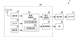
- FIG. 1 is a block diagram showing the main configuration of the ship 1.
- the ship 1 includes a hull control device 20, a power source 30, a propeller 31, and a rudder 40.
- the hull control device 20 includes an antenna 21, a positioning unit 22, a sensor 23, a hull control unit 24, an operation unit 25, a power control unit 26, and a rudder control unit 27.
- the hull control unit 24 includes a disturbance direction estimation unit 240 and a position setting unit 241.
- the power source 30 and the propeller 31 correspond to the “propulsion generator” of the present invention.
- the rudder 40 corresponds to the “movement direction adjusting unit” of the present invention.
- the disturbance direction estimation unit 240 corresponds to “disturbance direction estimation means” of the present invention.
- the positioning unit 22 corresponds to the “position detecting means” of the present invention.
- the position setting unit 241 corresponds to the “position setting unit” of the present invention.
- the hull control unit 24 corresponds to the “control unit” of the present invention.
- Ship 1 is a 1-axis 1 rudder ship. That is, the direction of the propulsive force by the propeller 31 is the heading direction of the ship 1. Moreover, the ship 1 is provided with one rudder 40 as shown in FIG. Therefore, the ship 1 moves only in the heading direction of the ship 1.
- the antenna 21 receives a GPS (; Global Positioning System) positioning signal and outputs it to the positioning unit 22.
- the positioning unit 22 executes a positioning calculation using the GPS positioning signal and calculates the position of the ship 1. This positioning calculation is executed at every positioning timing set in advance.
- the positioning unit 22 outputs the calculated position of the ship 1 to the hull control unit 24.
- the sensor 23 includes, for example, necessary ones among a heading sensor that detects the heading, a wind direction sensor, a wind speed sensor, a tide meter, and the like.
- the sensor 23 outputs the detected heading, wind direction, wind speed, and tidal current to the hull control unit 24 every predetermined time.
- the sensor 23 may be attached as necessary, and is not an essential configuration of the present invention.
- the hull control unit 24 can estimate the heading of the bow from a change in the current position when the sensor 23 is not provided with a heading sensor.
- the operation unit 25 is a so-called user interface device, and outputs an operation input by the user to the hull control unit 24.
- the position setting unit 241 stores a target position that the ship 1 should pass through. Further, the position setting unit 241 stores a starting position at which the ship 1 starts to flow and a target bow direction that is the heading direction when the ship 1 is flown. The target position is input from the user via the operation unit 25.
- the disturbance azimuth estimating unit 240 estimates the azimuth of the disturbance with respect to the ship 1.
- Disturbance mainly consists of tidal current and wind.
- the hull control unit 24 sets control information for maintaining the heading of the ship 1 or moving the ship 1 to a predetermined position.
- the control information includes, for example, power amount information and propulsion direction information.
- Information on the amount of power is output to the power control unit 26.
- Information on the propulsion direction is output to the rudder control unit 27.
- the power control unit 26 drives and controls the power source 30 based on the information on the amount of power.
- the power source 30 is composed of a diesel engine or a motor.
- the power source 30 gives the propeller 31 the power generated based on the control of the power control unit 26.
- the power source 30 may be a hybrid mechanism including both a diesel engine and a motor.
- the rudder control unit 27 adjusts the rudder angle of the rudder 40 with respect to the heading direction based on the propulsion direction information output from the hull control unit 24.
- the ship 1 moves toward the departure position by controlling the propulsion force of the propeller 31 and the rudder angle of the rudder 40, or passes through the target position while keeping the heading toward the target heading.
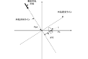
- FIG. 2 is a diagram illustrating an example of estimating the disturbance direction.
- the reference position Ppd is a reference position used for disturbance direction estimation processing.
- the current position Ps is the current position of the ship 1.
- the user inputs the position information of the reference position Pbd using the operation unit 25.
- the input position information is output to the position setting unit 241 and stored.
- the reference position Ppd may be a latitude and longitude, or may be set relatively to 10 m in the port direction.
- the disturbance direction estimation unit 240 estimates the disturbance direction.
- the disturbance direction as the initial value may be any direction, for example, a true south direction.
- the hull control unit 24 outputs propulsion direction information so that the bow direction faces the estimated disturbance direction.
- the disturbance azimuth estimation unit 240 obtains a distance XTE (; Cross Track Error) between the current position Ps and a disturbance facing line that passes through the reference position Ppd and is parallel to the estimated disturbance azimuth. .
- XTE Cross Track Error
- XTE becomes 0 when the estimated disturbance azimuth coincides with the bow azimuth and the ship 1 moves toward the reference position Ppd.
- the disturbance azimuth estimation unit 240 obtains XTE every predetermined time, and calculates a new disturbance azimuth by subtracting the estimated disturbance azimuth and the correction value based on XTE as shown in the following formula 1. calculate.
- the disturbance azimuth estimation unit 240 estimates the estimated disturbance so that XTE becomes 0 based on the proportional component of XTE (the term of the proportional correction gain in Equation 1) and the integral component of XTE (the term of ⁇ in Equation 1). Update the bearing.
- the disturbance azimuth estimation unit 240 includes convergence (XTE becomes 0) by including a differential term of XTE (a term of the second integral correction gain of Equation 1) in the integral component of XTE (term of ⁇ in Equation 1).
- the estimated disturbance direction can be brought close to the actual disturbance direction early and smoothly until convergence.
- the hull control unit 24 outputs propulsion direction control information so that the bow direction faces the updated estimated disturbance direction.
- the hull control unit 24 switches between the flow control and the movement control to the departure position while always performing the direction control.
- direction control is control which makes a bow azimuth
- the flow control is a control that is flowed by a disturbance from a starting position where the flow starts. Control toward the departure position is control for moving the ship 1 to the departure position.
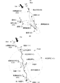
- the ship 1 (n) indicates the ship 1 at a predetermined position (n).
- the heading ADb indicates the heading of the ship 1.
- the disturbance vector Ddr is a vector indicating the direction and magnitude of the disturbance (consisting of wind and tidal current).
- the wind vector Wnd is a vector indicating the wind direction and the wind speed.
- the declination ⁇ is the declination between the heading ADb and the target heading ADd.
- the declination ⁇ is a plus (+) angle if the heading ADb is clockwise with respect to the target heading ADd, and the heading ADb is counterclockwise with respect to the target heading ADd. If so, the angle is minus ( ⁇ ).
- the hull control unit 24 sets the target bow direction ADd so as to face the direction of the wind vector Wnd obtained by the wind direction sensor provided in the sensor 23. Then, the hull control unit 24 outputs propulsion direction information so that the bow direction ADb becomes the target bow direction ADd.
- the hull control unit 24 may set the target bow direction ADd so as to face the estimated direction of the disturbance vector Ddr.
- the ship 1 (21) has an azimuth in which the bow azimuth ADb is counterclockwise with respect to the target bow azimuth ADd. That is, the deviation angle ⁇ between the target heading ADd and the heading ADb is a negative angle.
- the hull control unit 24 provides information on the propulsion direction for turning the rudder 40 to the left when the absolute value of the negative declination ⁇ is equal to or greater than a predetermined threshold. Then, information on the amount of power for moving the ship 1 (21) backward is output. Then, the ship 1 moves backward as the adjustment channel 301 makes the negative deviation angle ⁇ approach 0 degree.
- the deflection angle ⁇ approaches 0 degrees compared to the deflection angle ⁇ in the state of the ship 1 (21).
- the hull control part 24 outputs the information of the propulsion direction which turns the rudder 40 to the right, and the information of the motive power which advances the ship 1 (22).
- the ship 1 (22) moves forward while making the negative declination ⁇ closer to 0 degrees as in the adjustment channel 302.
- the deflection angle ⁇ is almost zero. That is, the heading ADb matches the target heading ADd as shown in the ship 1 (23).
- the hull control unit 24 moves the ship 1 backward and information on the propulsion direction to turn the rudder 40 to the right when the declination ⁇ is a positive angle and the absolute value of the declination ⁇ is equal to or greater than a predetermined threshold. Output power information. Next, the hull control unit 24 outputs information on the propulsion direction for turning the rudder 40 to the left and information on the amount of power for moving the ship 1 forward.
- the hull control unit 24 performs the backward control first, but may perform the forward control.
- the position setting unit 241 stores the target position Pp input from the user via the operation unit 25. Further, the position setting unit 241 stores the departure position Pf. The starting position Pf is set as the current position Ps of the ship 1 as an initial value.
- the hull control unit 24 is flowed and starts control when a start instruction is input from the user via the operation unit 25.
- the start instruction is input only once by the user, and the flow control executed thereafter is automatically started by the hull control unit 24.
- the hull control unit 24 performs heading control even during flow control. Then, even during the flow control, the ship 1 is flowed by the disturbance Ddr while the heading ADb is opposed to the direction of the wind vector Wnd by the direction control. The fisherman can perform drift fishing because the ship 1 is swept with the heading ADb facing the wind direction.
- the ship 1 can prevent the direction in which the target position Pp to pass from the end position Pe, which is the position where the flow has ended, from deviating from the heading ADb (for example, orthogonal).
- the ship 1 when returning to the departure position Pf, the ship 1 does not need to largely turn the rudder 40 in order to pass through the target position Pp, and does not need to go through a useless route.
- the bow direction ADb can be set as the target bow direction ADd at the departure position Pf.
- the position setting unit 241 obtains the flow channel 101 shown in FIG. 3B during flow control. That is, the position setting unit 241 obtains the channel 101 by flowing from the history of the position Ps obtained every predetermined time while the ship 1 is made to flow from the start position Pf to the end position Pe.
- the hull control unit 24 switches the flow control to movement control to the departure position while performing direction control.
- the position setting unit 241 changes the departure position Pf [n] to a new departure position Pf [n + 1] when switching to the movement control to the departure position.
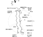
- FIG. 4 (A) is a diagram showing the distance from the target position Pp to the route 101.
- the position Ps (t) is the position of the ship 1 at time t.
- the position Ps (t) is the closest position on the route 101 that is flowed at time t and is the closest position to the target position Pp.
- the shortest distance from the position Ps (t) to the target position Pp is a distance L as shown in FIG.
- the position setting unit 241 changes the starting position Pf [n] based on the error vector VecE that is a vector toward the target position Pp with the position Ps (t) as a reference.
- the error vector VecE includes the influence of the displacement of the position Ps of the ship 1 that occurs because the ship 1 moves forward or backward to maintain the bow direction ADb at the target bow direction ADd.
- the direction and magnitude of the disturbance on the sea can be regarded as being constant regardless of the position as long as it is within a predetermined range centered on the starting position Pf [n].
- the position setting unit 241 changes the starting position Pf based on the deviation so as to offset the influence of the deviation of the position Ps caused by the control for maintaining the bow direction ADb.
- the position setting unit 241 sets the position moved by the correction vector VecM from the starting position Pf [n] as a new starting position Pf [n + 1].
- the correction vector VecM is parallel to the error vector VecE, and the magnitude is a predetermined coefficient ⁇ times.
- the predetermined coefficient ⁇ is a value greater than 0 and less than or equal to 1. That is, the starting position Pf [n + 1] is calculated as follows.
- the hull control unit 24 outputs control information that passes the target position Pp when a new departure position Pf [n + 1] is set.
- the hull control unit 24 uses the end position Pe as a reference, the propulsion vector 1 from the end position Pe to the target position Pp, and the target position Pp as a reference, and a new departure position Pf [n + 1 from the target position Pp.
- the control information is output so that the ship 1 moves with the combined propulsion vector obtained by weighted addition of the propulsion vector 2 toward the vehicle.
- the hull control unit 24 changes the addition ratio based on the distance from the current position Ps to the target position Pp. For example, the hull control unit 24 adds so that the addition ratio of the propulsion vector 2 becomes higher as the distance from the current position Ps to the target position Pp is shorter. Further, the hull control unit 24 adds so that the addition ratio of the propulsion vector 1 becomes higher as the distance from the current position Ps to the target position Pp is longer.
- the hull control unit 24 When the hull control unit 24 passes the target position Pp, the hull control unit 24 outputs control information such that the ship 1 moves with a combined propulsion vector obtained by weighting and adding the propulsion vector 2 and the propulsion vector 3.
- the propulsion vector 3 is set so as to face the wind vector Wnd at the departure position Pf [n + 1] with the new departure position Pf [n + 1] as a reference. Also in this case, the hull control unit 24 adds so that the addition ratio of the propulsion vector 3 becomes higher as the distance from the current position Ps to the departure position Pf [n + 1] is shorter.
- the hull control unit 24 adds so that the addition ratio of the propulsion vector 2 increases as the distance from the current position Ps to the departure position Pf [n + 1] increases. Note that the speed of the wind vector Wnd is obtained by an anemometer provided in the sensor 23.
- the hull control unit 24 passes the target position Pp, and when the ship 1 reaches the departure position Pf [n + 1], the hull control unit 24 is flowed while maintaining the heading control. Return to control automatically.
- FIG. 5 is a diagram illustrating an example in which the ship 1 is flown from the starting position Pf [n + 1] and is flown by control.
- the ship 1 (14) is flowed from the starting position Pf [n + 1] and controlled, the ship 1 (14) is flowed to the end position Pe [n + 1] along the route 102.
- the deviation between the target position Pp and the position Ps of the ship 1 is corrected when the departure position Pf [n + 1] is corrected so as to cancel the error vector VecE. Smaller than
- the hull control unit 24 is made to flow along the disturbance and repeats the process of changing the departure position Pf when the hull control unit 24 is made to flow from the target position Pp to a predetermined distance. As a result, the ship 1 gradually flows along the route approaching the target position Pp.
- the departure position Pf [n + 1] is changed so as to cancel out the displacement of the position of the ship 1 based on the shortest distance from the target position Pp to the route 101.
- the change amount (distance) of the departure position Pf is minimized, the marine vessel 1 can travel the target position efficiently and repeatedly with a shorter navigation distance.
- the change amount of the departure position Pf [n + 1] is calculated based on the distance from the target position Pp to the route 101 and a predetermined coefficient ⁇ .
- the ship 1 converges so as to gradually eliminate the shift without correcting the shift suddenly.
- the position setting unit 241 changes the departure position Pf based on the shortest distance from the route 101 to the target position Pp. It is also possible to change the position Pf.
- the position setting unit 241 can obtain the error vector VecE by using the distance from the position of the ship 1 to the target position Pp calculated before and after the timing at which the shortest distance is detected in addition to the shortest distance.
- the position setting unit 241 uses the average distance of the respective positions from the position Ps (t ⁇ 1), the position Ps (t), and the position Ps (t + 1) to the target position Pp shown in FIG. it can.
- the time t is a time after a predetermined time (for example, 3 seconds) from the time t-1.
- the time t + 1 is a time after a predetermined time (for example, 3 seconds) from the time t.
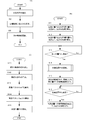
- FIG. 6 is a flowchart showing a processing flow of the hull control device 20.
- FIG. 6A is a flowchart showing the azimuth control.
- FIG. 6B is a flowchart showing switching between flow control and movement control to the starting position.
- FIG. 6C is a flowchart showing the flow of the process of updating (changing) the starting position.
- the disturbance direction estimating unit 240 estimates the disturbance direction (S1). Then, the position setting unit 241 sets the target bow direction ADd so as to face the disturbance direction estimated in step S1 (S2). Then, the hull control unit 24 starts the azimuth control so that the bow azimuth ADb becomes the target bow azimuth ADd (S3).
- the ship 1 Regardless of the flow control and the movement control to the departure position, the ship 1 always performs steps S1 to S3 every predetermined time so that the heading ADb faces the disturbance direction.
- the position setting unit 241 stores the departure position Pf as the current position Ps when receiving the flow start control instruction.
- the position setting unit 241 also stores the target position Pp (S11). However, the target position Pp is input from the user via the operation unit 25.
- the hull control unit 24 starts the control (S12).
- the hull control unit 24 determines whether or not the ship 1 has reached the end position Pe that is a distance R away from the target position Pp based on the distance between the target position Pp and the current position Ps (S13). When the ship 1 reaches the end position Pe (S13: Yes), the hull control unit 24 proceeds to step S14. If the ship 1 has not reached the end position Pe (S13: No), the hull control unit 24 is flowed and continues control.
- the hull control unit 24 updates the departure position Pf when proceeding to step S14.
- the flow of the update process for the departure position Pf will be described with reference to FIG.
- the position setting unit 241 reads the navigation route by flowing (S141). Then, the position setting unit 241 obtains the closest position Px that is flown and is closest to the target position Pp (S142).
- the position setting unit 241 obtains an error vector VecE based on the closest position Px and the target position Pp (S143). Then, the position setting unit 241 obtains a correction vector VecM using the error vector VecE and a predetermined coefficient ⁇ (S144).
- the position setting unit 241 updates the departure position Pf based on the correction vector VecM (S145).
- the hull controller 24 stops the flow control and performs movement control to the updated departure position Pf (S15).
- the hull control unit 24 determines whether or not the departure position Pf has been reached (S16). When the ship 1 reaches the departure position Pf (S16: Yes), the hull control unit 24 proceeds to step S17. If the ship 1 has not reached the departure position Pf (S16: No), the hull control unit 24 continues the movement control to the departure position Pf.
- the ship hull control part 24 will stop the movement control to the departure position Pf, if it progresses to step S17. Then, the hull control unit 24 is flowed and returns to control (S17).
- the hull control device 20 executes the flow control and the movement control to the departure position while performing the azimuth control.
- each functional unit is an example of hardware.
- the positioning unit 22, the hull control unit 24, the power control unit 26, and the rudder control unit 27 can be realized by software. That is, the above-described processing can be realized by programming the processing of these functional units and storing them in a storage medium, and reading out and executing the hull control program by a computing unit (computer or the like). .
- a ship is shown as an example of a moving body.
- the configuration and processing of can be applied.
Landscapes
- Engineering & Computer Science (AREA)
- Ocean & Marine Engineering (AREA)
- Combustion & Propulsion (AREA)
- Mechanical Engineering (AREA)
- Chemical & Material Sciences (AREA)
- Radar, Positioning & Navigation (AREA)
- Remote Sensing (AREA)
- General Physics & Mathematics (AREA)
- Physics & Mathematics (AREA)
- Automation & Control Theory (AREA)
- Life Sciences & Earth Sciences (AREA)
- Atmospheric Sciences (AREA)
- Environmental & Geological Engineering (AREA)
- Control Of Position, Course, Altitude, Or Attitude Of Moving Bodies (AREA)
- Navigation (AREA)
Abstract
Description

船体制御部24は、図4(B)に示すように、新たな出発位置Pf[n+1]が設定されると、目標位置Ppを通過するような制御情報を出力する。
20…船体制御装置
21…アンテナ
22…測位部
23…センサ
24…船体制御部
25…操作部
26…動力制御部
27…舵制御部
30…動力源
31…プロペラ
40…舵
240…外乱方位推定部
241…位置設定部
Claims (7)
- 特定の一方向に移動体を推進させる推進力発生部と、該推進力により移動する方向を調整する移動方向調整部とを前記移動体に備える移動体制御装置であって、
前記移動体を移動させる外乱の方向を推定する外乱方向推定手段と、
前記移動体の向いている方向を検出する移動体方向検出手段と、
前記移動体の位置を検出する位置検出手段と、
目標位置および出発位置を設定する位置設定手段と、
前記移動体方向検出手段で検出した移動体の向いている方向が前記外乱方向推定手段で推定した外乱の方向に対向するように前記推進力発生部および前記移動方向調整部を制御し、
前記移動体が前記外乱によって前記位置設定手段に設定された目標位置から所定の距離以上流されると、前記出発位置に戻り、かつ前記出発位置において前記移動体の向いている方向が前記外乱の方向に対向するように前記推進力発生部および前記移動方向調整部を制御する制御手段と、
を備え、
前記位置設定手段は、前記位置検出手段が検出した位置と前記目標位置との距離に基づいて、前記出発位置を変更する
移動体制御装置。 - 請求項1に記載の移動体制御装置であって、
前記位置設定手段は、前記外乱によって流される前記移動体が前記目標位置に最も近づいたときの該移動体の位置と前記目標位置との距離に基づいて、前記出発位置を変更する
移動体制御装置。 - 請求項1に記載の移動体制御装置であって、
前記位置設定手段は、前記外乱によって流される前記移動体が前記目標位置に最も近づいたタイミングを含む所定の時間に算出した前記移動体の位置と前記目標位置との平均の距離に基づいて、前記出発位置を変更する
移動体制御装置。 - 請求項1乃至請求項3のいずれかに記載の移動体制御装置であって、
前記位置設定手段は、前記距離および所定の係数に基づいて、前記出発位置を変更する
移動体制御装置。 - 請求項1乃至請求項4のいずれかに記載の移動体制御装置であって、
前記外乱は、前記移動体を移動させる風及び潮流であり、
前記制御手段は、前記移動体方向検出手段で検出した移動体の向いている方向が風の方向に対向するように前記推進力発生部および前記移動方向調整部を制御する
移動体制御装置。 - 特定の一方向に移動体を推進させる推進力発生部と、該推進力により移動する方向を調整する移動方向調整部とを備える前記移動体を制御する移動体制御方法であって、
前記移動体を移動させる外乱の方向を推定する外乱方向推定ステップと、
前記移動体の向いている方向を検出する移動体方向検出ステップと、
前記移動体の位置を検出する位置検出ステップと、
前記移動体方向検出ステップで検出した移動体の向いている方向が前記外乱方向推定ステップで推定した外乱の方向に対向するように前記推進力発生部および前記移動方向調整部を制御する制御ステップと、
目標位置および出発位置を設定する位置設定ステップと、
からなり、
前記位置設定ステップは、前記位置検出ステップが検出した位置と前記目標位置との距離に基づいて、前記出発位置を変更し、
前記制御ステップは、前記移動体が前記外乱によって前記位置設定ステップに設定された目標位置から所定の距離以上流されると、前記出発位置に戻り、かつ前記出発位置において前記移動体の向いている方向が前記外乱の方向に対向するように前記推進力発生部および前記移動方向調整部を制御する
移動体制御方法。 - 特定の一方向に移動体を推進させる推進力発生部と、該推進力により移動する方向を調整する移動方向調整部とを前記移動体に備える移動体制御装置に実行される移動体制御プログラムであって、
前記移動体を移動させる外乱の方向を推定する外乱方向推定ステップと、
前記移動体の向いている方向を検出する移動体方向検出ステップと、
前記移動体の位置を検出する位置検出ステップと、
前記移動体方向検出ステップで検出した移動体の向いている方向が前記外乱方向推定ステップで推定した外乱の方向に対向するように前記推進力発生部および前記移動方向調整部を制御する制御ステップと、
目標位置および出発位置を設定する位置設定ステップと、
を実行し、
前記位置設定ステップは、前記位置検出ステップが検出した位置と前記目標位置との距離に基づいて、前記出発位置を変更し、
前記制御ステップは、前記移動体が前記外乱によって前記位置設定ステップに設定された目標位置から所定の距離以上流されると、前記出発位置に戻り、かつ前記出発位置において前記移動体の向いている方向が前記外乱の方向に対向するように前記推進力発生部および前記移動方向調整部を制御する、
移動体制御プログラム。
Priority Applications (2)
| Application Number | Priority Date | Filing Date | Title |
|---|---|---|---|
| US15/538,317 US10000270B2 (en) | 2014-12-22 | 2015-11-26 | Moving body control device, moving body control method, and moving body control program |
| JP2016566052A JP6370924B2 (ja) | 2014-12-22 | 2015-11-26 | 移動体制御装置、移動体制御方法、および移動体制御プログラム |
Applications Claiming Priority (2)
| Application Number | Priority Date | Filing Date | Title |
|---|---|---|---|
| JP2014258202 | 2014-12-22 | ||
| JP2014-258202 | 2014-12-22 |
Publications (1)
| Publication Number | Publication Date |
|---|---|
| WO2016104031A1 true WO2016104031A1 (ja) | 2016-06-30 |
Family
ID=56150063
Family Applications (1)
| Application Number | Title | Priority Date | Filing Date |
|---|---|---|---|
| PCT/JP2015/083152 Ceased WO2016104031A1 (ja) | 2014-12-22 | 2015-11-26 | 移動体制御装置、移動体制御方法、および移動体制御プログラム |
Country Status (3)
| Country | Link |
|---|---|
| US (1) | US10000270B2 (ja) |
| JP (1) | JP6370924B2 (ja) |
| WO (1) | WO2016104031A1 (ja) |
Cited By (16)
| Publication number | Priority date | Publication date | Assignee | Title |
|---|---|---|---|---|
| JP2018030571A (ja) * | 2016-08-25 | 2018-03-01 | ブランスウィック コーポレイションBrunswick Corporation | オブジェクト近傍の船舶の運動を制御する方法 |
| US10095232B1 (en) | 2016-03-01 | 2018-10-09 | Brunswick Corporation | Station keeping methods |
| WO2019016930A1 (ja) | 2017-07-21 | 2019-01-24 | 日本電気株式会社 | データ処理装置、駆動制御装置、移動体、データ処理方法、駆動制御方法、および記憶媒体 |
| US10198005B2 (en) | 2016-03-01 | 2019-02-05 | Brunswick Corporation | Station keeping and waypoint tracking methods |
| US10322787B2 (en) | 2016-03-01 | 2019-06-18 | Brunswick Corporation | Marine vessel station keeping systems and methods |
| US10324468B2 (en) | 2017-11-20 | 2019-06-18 | Brunswick Corporation | System and method for controlling a position of a marine vessel near an object |
| US10429845B2 (en) | 2017-11-20 | 2019-10-01 | Brunswick Corporation | System and method for controlling a position of a marine vessel near an object |
| US10633072B1 (en) | 2018-07-05 | 2020-04-28 | Brunswick Corporation | Methods for positioning marine vessels |
| US10671073B2 (en) | 2017-02-15 | 2020-06-02 | Brunswick Corporation | Station keeping system and method |
| US10845812B2 (en) | 2018-05-22 | 2020-11-24 | Brunswick Corporation | Methods for controlling movement of a marine vessel near an object |
| JP2021011158A (ja) * | 2019-07-05 | 2021-02-04 | 古野電気株式会社 | 船体制御装置、船体制御方法、および、船体制御プログラム |
| US11530022B1 (en) | 2018-07-10 | 2022-12-20 | Brunswick Corporation | Method for controlling heading of a marine vessel |
| US11643180B2 (en) | 2019-09-13 | 2023-05-09 | Furuno Electric Company Limited | Ship speed control device, ship speed controlling method, and ship speed control program |
| US11866142B2 (en) | 2019-09-13 | 2024-01-09 | Furuno Electric Company Limited | Hull control device, hull controlling method, and hull control program |
| US11866141B2 (en) | 2019-06-27 | 2024-01-09 | Furuno Electric Company Limited | Device, method, and program for controlling ship body |
| US11873067B2 (en) | 2019-06-28 | 2024-01-16 | Furuno Electric Company Limited | Device, method, and program for controlling ship body |
Families Citing this family (2)
| Publication number | Priority date | Publication date | Assignee | Title |
|---|---|---|---|---|
| WO2016104031A1 (ja) * | 2014-12-22 | 2016-06-30 | 古野電気株式会社 | 移動体制御装置、移動体制御方法、および移動体制御プログラム |
| JP7615263B1 (ja) * | 2023-09-29 | 2025-01-16 | 本田技研工業株式会社 | 移動体の制御装置、移動体の制御方法、およびプログラム |
Citations (5)
| Publication number | Priority date | Publication date | Assignee | Title |
|---|---|---|---|---|
| US5386368A (en) * | 1993-12-13 | 1995-01-31 | Johnson Fishing, Inc. | Apparatus for maintaining a boat in a fixed position |
| JP2002178990A (ja) * | 2000-12-14 | 2002-06-26 | Yokogawa Denshikiki Co Ltd | 自動航行装置 |
| JP2013151241A (ja) * | 2012-01-25 | 2013-08-08 | Marol Ltd | 船体用制御装置、船体用制御プログラムおよび船体の制御方法 |
| JP2014024421A (ja) * | 2012-07-26 | 2014-02-06 | Furuno Electric Co Ltd | 移動体制御装置、船体制御装置、船舶、移動体制御方法、および移動体制御プログラム |
| WO2014065147A1 (ja) * | 2012-10-22 | 2014-05-01 | 古野電気株式会社 | 船体制御方法および船体制御装置 |
Family Cites Families (21)
| Publication number | Priority date | Publication date | Assignee | Title |
|---|---|---|---|---|
| FR1537671A (fr) * | 1966-01-06 | 1968-09-07 | Inst Francais Du Petrole | Système d'ancrage dynamique automatique |
| US4513378A (en) * | 1981-10-20 | 1985-04-23 | Antkowiak Edward T | High-accuracy navigating apparatus with step-driven projected chart |
| DE3222054A1 (de) * | 1982-06-11 | 1983-12-15 | Schottel-Werft Josef Becker Gmbh & Co Kg, 5401 Spay | Vorrichtung zum vorgeben der bewegungsrichtung und kraft eines wasserfahrzeugs |
| US4542464A (en) * | 1982-08-06 | 1985-09-17 | The Brunton Company | Autopilot system |
| US4564909A (en) * | 1983-10-31 | 1986-01-14 | The Brunton Company | Error sensing system for vessels with absolute zero referencing |
| US4881080A (en) * | 1985-06-24 | 1989-11-14 | The United States Of America As Represented By The Secretary Of The Navy | Apparatus for and a method of determining compass headings |
| US5947051A (en) * | 1997-06-04 | 1999-09-07 | Geiger; Michael B. | Underwater self-propelled surface adhering robotically operated vehicle |
| US6144918A (en) * | 1998-12-15 | 2000-11-07 | Stanford University | Navigation data processing with filtering for refined position determination |
| JP4448960B2 (ja) * | 2001-07-12 | 2010-04-14 | ヤンマー株式会社 | スパンカの制御装置 |
| US8581688B2 (en) * | 2002-06-11 | 2013-11-12 | Intelligent Technologies International, Inc. | Coastal monitoring techniques |
| NL1031263C2 (nl) * | 2006-03-01 | 2007-09-04 | Univ Delft Tech | Vaartuig, bewegingsplatform, werkwijze voor het compenseren voor bewegingen van een vaartuig en gebruik van een Stewart platform. |
| US8082100B2 (en) * | 2007-10-19 | 2011-12-20 | Grace Ted V | Watercraft automation and aquatic effort data utilization |
| US8463470B2 (en) * | 2009-09-03 | 2013-06-11 | Johnson Outdoors Marine Electronics, Inc. | Shallow water highlight method and display systems |
| US8478464B2 (en) * | 2009-12-23 | 2013-07-02 | Brunswick Corporation | Systems and methods for orienting a marine vessel to enhance available thrust |
| JP2011218959A (ja) | 2010-04-09 | 2011-11-04 | Mitsui Eng & Shipbuild Co Ltd | バウスラスターを備えた船舶、及びこの船舶の航行方法と改修方法 |
| JP5572460B2 (ja) | 2010-07-09 | 2014-08-13 | マロール株式会社 | 船体用制御装置及び船体用制御プログラム並びに船体用制御プログラムを組み込んだ自動操舵装置 |
| US8761976B2 (en) * | 2010-07-16 | 2014-06-24 | Johnson Outdoors Inc. | System and method for controlling a trolling motor |
| US8645012B2 (en) * | 2010-08-20 | 2014-02-04 | Johnson Outdoors Inc. | System and method for automatically navigating a depth contour |
| US9377780B1 (en) * | 2013-03-14 | 2016-06-28 | Brunswick Corporation | Systems and methods for determining a heading value of a marine vessel |
| WO2016104031A1 (ja) * | 2014-12-22 | 2016-06-30 | 古野電気株式会社 | 移動体制御装置、移動体制御方法、および移動体制御プログラム |
| US9857794B1 (en) * | 2015-07-23 | 2018-01-02 | Brunswick Corporation | System for controlling position and speed of a marine vessel |
-
2015
- 2015-11-26 WO PCT/JP2015/083152 patent/WO2016104031A1/ja not_active Ceased
- 2015-11-26 JP JP2016566052A patent/JP6370924B2/ja not_active Expired - Fee Related
- 2015-11-26 US US15/538,317 patent/US10000270B2/en active Active
Patent Citations (5)
| Publication number | Priority date | Publication date | Assignee | Title |
|---|---|---|---|---|
| US5386368A (en) * | 1993-12-13 | 1995-01-31 | Johnson Fishing, Inc. | Apparatus for maintaining a boat in a fixed position |
| JP2002178990A (ja) * | 2000-12-14 | 2002-06-26 | Yokogawa Denshikiki Co Ltd | 自動航行装置 |
| JP2013151241A (ja) * | 2012-01-25 | 2013-08-08 | Marol Ltd | 船体用制御装置、船体用制御プログラムおよび船体の制御方法 |
| JP2014024421A (ja) * | 2012-07-26 | 2014-02-06 | Furuno Electric Co Ltd | 移動体制御装置、船体制御装置、船舶、移動体制御方法、および移動体制御プログラム |
| WO2014065147A1 (ja) * | 2012-10-22 | 2014-05-01 | 古野電気株式会社 | 船体制御方法および船体制御装置 |
Cited By (26)
| Publication number | Priority date | Publication date | Assignee | Title |
|---|---|---|---|---|
| US10640190B1 (en) | 2016-03-01 | 2020-05-05 | Brunswick Corporation | System and method for controlling course of a marine vessel |
| US10095232B1 (en) | 2016-03-01 | 2018-10-09 | Brunswick Corporation | Station keeping methods |
| US10845811B1 (en) | 2016-03-01 | 2020-11-24 | Brunswick Corporation | Station keeping methods |
| US10198005B2 (en) | 2016-03-01 | 2019-02-05 | Brunswick Corporation | Station keeping and waypoint tracking methods |
| US11260949B2 (en) | 2016-03-01 | 2022-03-01 | Brunswick Corporation | Marine vessel station keeping systems and methods |
| US10322787B2 (en) | 2016-03-01 | 2019-06-18 | Brunswick Corporation | Marine vessel station keeping systems and methods |
| US10795366B1 (en) | 2016-03-01 | 2020-10-06 | Brunswick Corporation | Vessel maneuvering methods and systems |
| JP2018030571A (ja) * | 2016-08-25 | 2018-03-01 | ブランスウィック コーポレイションBrunswick Corporation | オブジェクト近傍の船舶の運動を制御する方法 |
| US10259555B2 (en) | 2016-08-25 | 2019-04-16 | Brunswick Corporation | Methods for controlling movement of a marine vessel near an object |
| US12252224B2 (en) | 2017-02-15 | 2025-03-18 | Brunswick Corporation | Marine vessel station keeping to reduce wear and noise on propulsion system |
| US10671073B2 (en) | 2017-02-15 | 2020-06-02 | Brunswick Corporation | Station keeping system and method |
| US11247753B2 (en) | 2017-02-15 | 2022-02-15 | Brunswick Corporation | Station keeping methods |
| WO2019016930A1 (ja) | 2017-07-21 | 2019-01-24 | 日本電気株式会社 | データ処理装置、駆動制御装置、移動体、データ処理方法、駆動制御方法、および記憶媒体 |
| US11402855B2 (en) | 2017-07-21 | 2022-08-02 | Nec Corporation | Processing device, drive control device, data processing method, and storage medium for attitude control of moving body based on wind conditions |
| US10429845B2 (en) | 2017-11-20 | 2019-10-01 | Brunswick Corporation | System and method for controlling a position of a marine vessel near an object |
| US10324468B2 (en) | 2017-11-20 | 2019-06-18 | Brunswick Corporation | System and method for controlling a position of a marine vessel near an object |
| US10845812B2 (en) | 2018-05-22 | 2020-11-24 | Brunswick Corporation | Methods for controlling movement of a marine vessel near an object |
| US10633072B1 (en) | 2018-07-05 | 2020-04-28 | Brunswick Corporation | Methods for positioning marine vessels |
| US11530022B1 (en) | 2018-07-10 | 2022-12-20 | Brunswick Corporation | Method for controlling heading of a marine vessel |
| US11866141B2 (en) | 2019-06-27 | 2024-01-09 | Furuno Electric Company Limited | Device, method, and program for controlling ship body |
| US11873067B2 (en) | 2019-06-28 | 2024-01-16 | Furuno Electric Company Limited | Device, method, and program for controlling ship body |
| JP2021011158A (ja) * | 2019-07-05 | 2021-02-04 | 古野電気株式会社 | 船体制御装置、船体制御方法、および、船体制御プログラム |
| JP7263158B2 (ja) | 2019-07-05 | 2023-04-24 | 古野電気株式会社 | 船体制御装置、船体制御方法、および、船体制御プログラム |
| US11884371B2 (en) | 2019-07-05 | 2024-01-30 | Furuno Electric Company Limited | Device, method, and program for controlling ship body |
| US11643180B2 (en) | 2019-09-13 | 2023-05-09 | Furuno Electric Company Limited | Ship speed control device, ship speed controlling method, and ship speed control program |
| US11866142B2 (en) | 2019-09-13 | 2024-01-09 | Furuno Electric Company Limited | Hull control device, hull controlling method, and hull control program |
Also Published As
| Publication number | Publication date |
|---|---|
| JPWO2016104031A1 (ja) | 2017-09-14 |
| US20170349258A1 (en) | 2017-12-07 |
| JP6370924B2 (ja) | 2018-08-08 |
| US10000270B2 (en) | 2018-06-19 |
Similar Documents
| Publication | Publication Date | Title |
|---|---|---|
| JP6370924B2 (ja) | 移動体制御装置、移動体制御方法、および移動体制御プログラム | |
| JP6821437B2 (ja) | 移動体制御装置、移動体制御方法、および移動体制御プログラム | |
| JP5957695B2 (ja) | 移動体制御装置、船体制御装置、船舶、移動体制御方法、および移動体制御プログラム | |
| US10775808B2 (en) | Boat maneuvering control method for boat and boat maneuvering control system for boat | |
| JPWO2016104030A6 (ja) | 移動体制御装置、移動体制御方法、および移動体制御プログラム | |
| US9771138B2 (en) | Boat maneuvering control method for boat and boat maneuvering control system for boat | |
| JP5042906B2 (ja) | 船舶用自動操舵装置 | |
| US11597488B2 (en) | Ship maneuvering system, ship, and ship maneuvering method | |
| KR20230011310A (ko) | 선박의 자동 유도 방법, 선박의 자동 유도 프로그램, 선박의 자동 유도 시스템 및 선박 | |
| JP2010173589A (ja) | 船舶用位置保持制御装置 | |
| JP2017105403A (ja) | 操船装置 | |
| WO2014065147A1 (ja) | 船体制御方法および船体制御装置 | |
| JP7618502B2 (ja) | 船舶用自動操舵装置 | |
| US11573087B1 (en) | Boat maneuvering control method for boat and boat maneuvering control system for boat | |
| JP6191984B2 (ja) | 船舶の操舵方法及び船舶の自動操舵装置 | |
| US20190092443A1 (en) | Maritime drift control system | |
| JP6450595B2 (ja) | 移動体制御装置、移動体制御方法、および移動体制御プログラム | |
| KR102521829B1 (ko) | 키 제어 장치 및 선박 | |
| US12013699B1 (en) | Boat maneuvering control method for boat and boat maneuvering control system for boat | |
| KR102558824B1 (ko) | 연료 제어 장치 및 키 제어 장치 | |
| JP7709898B2 (ja) | 船舶用自動操舵装置 | |
| JP5499508B2 (ja) | 船舶用方位制御装置 | |
| JP2024067882A (ja) | 船舶用自動操舵装置 | |
| JP2002145193A (ja) | 外力を利用した舶用定点保持方法とその装置 |
Legal Events
| Date | Code | Title | Description |
|---|---|---|---|
| 121 | Ep: the epo has been informed by wipo that ep was designated in this application |
Ref document number: 15872600 Country of ref document: EP Kind code of ref document: A1 |
|
| ENP | Entry into the national phase |
Ref document number: 2016566052 Country of ref document: JP Kind code of ref document: A |
|
| WWE | Wipo information: entry into national phase |
Ref document number: 15538317 Country of ref document: US |
|
| NENP | Non-entry into the national phase |
Ref country code: DE |
|
| 122 | Ep: pct application non-entry in european phase |
Ref document number: 15872600 Country of ref document: EP Kind code of ref document: A1 |