WO2016103711A1 - 蓄熱式空気調和機 - Google Patents
蓄熱式空気調和機 Download PDFInfo
- Publication number
- WO2016103711A1 WO2016103711A1 PCT/JP2015/006449 JP2015006449W WO2016103711A1 WO 2016103711 A1 WO2016103711 A1 WO 2016103711A1 JP 2015006449 W JP2015006449 W JP 2015006449W WO 2016103711 A1 WO2016103711 A1 WO 2016103711A1
- Authority
- WO
- WIPO (PCT)
- Prior art keywords
- heat storage
- compressor
- refrigerant
- heat exchanger
- heat
- Prior art date
Links
Images


Classifications
-
- F—MECHANICAL ENGINEERING; LIGHTING; HEATING; WEAPONS; BLASTING
- F25—REFRIGERATION OR COOLING; COMBINED HEATING AND REFRIGERATION SYSTEMS; HEAT PUMP SYSTEMS; MANUFACTURE OR STORAGE OF ICE; LIQUEFACTION SOLIDIFICATION OF GASES
- F25B—REFRIGERATION MACHINES, PLANTS OR SYSTEMS; COMBINED HEATING AND REFRIGERATION SYSTEMS; HEAT PUMP SYSTEMS
- F25B13/00—Compression machines, plants or systems, with reversible cycle
-
- F—MECHANICAL ENGINEERING; LIGHTING; HEATING; WEAPONS; BLASTING
- F24—HEATING; RANGES; VENTILATING
- F24F—AIR-CONDITIONING; AIR-HUMIDIFICATION; VENTILATION; USE OF AIR CURRENTS FOR SCREENING
- F24F11/00—Control or safety arrangements
- F24F11/89—Arrangement or mounting of control or safety devices
-
- F—MECHANICAL ENGINEERING; LIGHTING; HEATING; WEAPONS; BLASTING
- F24—HEATING; RANGES; VENTILATING
- F24F—AIR-CONDITIONING; AIR-HUMIDIFICATION; VENTILATION; USE OF AIR CURRENTS FOR SCREENING
- F24F5/00—Air-conditioning systems or apparatus not covered by F24F1/00 or F24F3/00, e.g. using solar heat or combined with household units such as an oven or water heater
- F24F5/0007—Air-conditioning systems or apparatus not covered by F24F1/00 or F24F3/00, e.g. using solar heat or combined with household units such as an oven or water heater cooling apparatus specially adapted for use in air-conditioning
- F24F5/001—Compression cycle type
-
- F—MECHANICAL ENGINEERING; LIGHTING; HEATING; WEAPONS; BLASTING
- F24—HEATING; RANGES; VENTILATING
- F24F—AIR-CONDITIONING; AIR-HUMIDIFICATION; VENTILATION; USE OF AIR CURRENTS FOR SCREENING
- F24F5/00—Air-conditioning systems or apparatus not covered by F24F1/00 or F24F3/00, e.g. using solar heat or combined with household units such as an oven or water heater
- F24F5/0007—Air-conditioning systems or apparatus not covered by F24F1/00 or F24F3/00, e.g. using solar heat or combined with household units such as an oven or water heater cooling apparatus specially adapted for use in air-conditioning
- F24F5/0017—Air-conditioning systems or apparatus not covered by F24F1/00 or F24F3/00, e.g. using solar heat or combined with household units such as an oven or water heater cooling apparatus specially adapted for use in air-conditioning using cold storage bodies, e.g. ice
-
- F—MECHANICAL ENGINEERING; LIGHTING; HEATING; WEAPONS; BLASTING
- F25—REFRIGERATION OR COOLING; COMBINED HEATING AND REFRIGERATION SYSTEMS; HEAT PUMP SYSTEMS; MANUFACTURE OR STORAGE OF ICE; LIQUEFACTION SOLIDIFICATION OF GASES
- F25B—REFRIGERATION MACHINES, PLANTS OR SYSTEMS; COMBINED HEATING AND REFRIGERATION SYSTEMS; HEAT PUMP SYSTEMS
- F25B41/00—Fluid-circulation arrangements
- F25B41/20—Disposition of valves, e.g. of on-off valves or flow control valves
- F25B41/24—Arrangement of shut-off valves for disconnecting a part of the refrigerant cycle, e.g. an outdoor part
-
- F—MECHANICAL ENGINEERING; LIGHTING; HEATING; WEAPONS; BLASTING
- F25—REFRIGERATION OR COOLING; COMBINED HEATING AND REFRIGERATION SYSTEMS; HEAT PUMP SYSTEMS; MANUFACTURE OR STORAGE OF ICE; LIQUEFACTION SOLIDIFICATION OF GASES
- F25B—REFRIGERATION MACHINES, PLANTS OR SYSTEMS; COMBINED HEATING AND REFRIGERATION SYSTEMS; HEAT PUMP SYSTEMS
- F25B49/00—Arrangement or mounting of control or safety devices
- F25B49/02—Arrangement or mounting of control or safety devices for compression type machines, plants or systems
- F25B49/022—Compressor control arrangements
-
- F—MECHANICAL ENGINEERING; LIGHTING; HEATING; WEAPONS; BLASTING
- F25—REFRIGERATION OR COOLING; COMBINED HEATING AND REFRIGERATION SYSTEMS; HEAT PUMP SYSTEMS; MANUFACTURE OR STORAGE OF ICE; LIQUEFACTION SOLIDIFICATION OF GASES
- F25B—REFRIGERATION MACHINES, PLANTS OR SYSTEMS; COMBINED HEATING AND REFRIGERATION SYSTEMS; HEAT PUMP SYSTEMS
- F25B2313/00—Compression machines, plants or systems with reversible cycle not otherwise provided for
- F25B2313/006—Compression machines, plants or systems with reversible cycle not otherwise provided for two pipes connecting the outdoor side to the indoor side with multiple indoor units
-
- F—MECHANICAL ENGINEERING; LIGHTING; HEATING; WEAPONS; BLASTING
- F25—REFRIGERATION OR COOLING; COMBINED HEATING AND REFRIGERATION SYSTEMS; HEAT PUMP SYSTEMS; MANUFACTURE OR STORAGE OF ICE; LIQUEFACTION SOLIDIFICATION OF GASES
- F25B—REFRIGERATION MACHINES, PLANTS OR SYSTEMS; COMBINED HEATING AND REFRIGERATION SYSTEMS; HEAT PUMP SYSTEMS
- F25B2313/00—Compression machines, plants or systems with reversible cycle not otherwise provided for
- F25B2313/009—Compression machines, plants or systems with reversible cycle not otherwise provided for indoor unit in circulation with outdoor unit in first operation mode, indoor unit in circulation with an other heat exchanger in second operation mode or outdoor unit in circulation with an other heat exchanger in third operation mode
-
- F—MECHANICAL ENGINEERING; LIGHTING; HEATING; WEAPONS; BLASTING
- F25—REFRIGERATION OR COOLING; COMBINED HEATING AND REFRIGERATION SYSTEMS; HEAT PUMP SYSTEMS; MANUFACTURE OR STORAGE OF ICE; LIQUEFACTION SOLIDIFICATION OF GASES
- F25B—REFRIGERATION MACHINES, PLANTS OR SYSTEMS; COMBINED HEATING AND REFRIGERATION SYSTEMS; HEAT PUMP SYSTEMS
- F25B2313/00—Compression machines, plants or systems with reversible cycle not otherwise provided for
- F25B2313/023—Compression machines, plants or systems with reversible cycle not otherwise provided for using multiple indoor units
- F25B2313/0232—Compression machines, plants or systems with reversible cycle not otherwise provided for using multiple indoor units with bypasses
-
- F—MECHANICAL ENGINEERING; LIGHTING; HEATING; WEAPONS; BLASTING
- F25—REFRIGERATION OR COOLING; COMBINED HEATING AND REFRIGERATION SYSTEMS; HEAT PUMP SYSTEMS; MANUFACTURE OR STORAGE OF ICE; LIQUEFACTION SOLIDIFICATION OF GASES
- F25B—REFRIGERATION MACHINES, PLANTS OR SYSTEMS; COMBINED HEATING AND REFRIGERATION SYSTEMS; HEAT PUMP SYSTEMS
- F25B2313/00—Compression machines, plants or systems with reversible cycle not otherwise provided for
- F25B2313/023—Compression machines, plants or systems with reversible cycle not otherwise provided for using multiple indoor units
- F25B2313/0233—Compression machines, plants or systems with reversible cycle not otherwise provided for using multiple indoor units in parallel arrangements
-
- F—MECHANICAL ENGINEERING; LIGHTING; HEATING; WEAPONS; BLASTING
- F25—REFRIGERATION OR COOLING; COMBINED HEATING AND REFRIGERATION SYSTEMS; HEAT PUMP SYSTEMS; MANUFACTURE OR STORAGE OF ICE; LIQUEFACTION SOLIDIFICATION OF GASES
- F25B—REFRIGERATION MACHINES, PLANTS OR SYSTEMS; COMBINED HEATING AND REFRIGERATION SYSTEMS; HEAT PUMP SYSTEMS
- F25B2313/00—Compression machines, plants or systems with reversible cycle not otherwise provided for
- F25B2313/027—Compression machines, plants or systems with reversible cycle not otherwise provided for characterised by the reversing means
- F25B2313/02731—Compression machines, plants or systems with reversible cycle not otherwise provided for characterised by the reversing means using one three-way valve
-
- F—MECHANICAL ENGINEERING; LIGHTING; HEATING; WEAPONS; BLASTING
- F25—REFRIGERATION OR COOLING; COMBINED HEATING AND REFRIGERATION SYSTEMS; HEAT PUMP SYSTEMS; MANUFACTURE OR STORAGE OF ICE; LIQUEFACTION SOLIDIFICATION OF GASES
- F25B—REFRIGERATION MACHINES, PLANTS OR SYSTEMS; COMBINED HEATING AND REFRIGERATION SYSTEMS; HEAT PUMP SYSTEMS
- F25B2400/00—General features or devices for refrigeration machines, plants or systems, combined heating and refrigeration systems or heat-pump systems, i.e. not limited to a particular subgroup of F25B
- F25B2400/13—Economisers
-
- F—MECHANICAL ENGINEERING; LIGHTING; HEATING; WEAPONS; BLASTING
- F25—REFRIGERATION OR COOLING; COMBINED HEATING AND REFRIGERATION SYSTEMS; HEAT PUMP SYSTEMS; MANUFACTURE OR STORAGE OF ICE; LIQUEFACTION SOLIDIFICATION OF GASES
- F25B—REFRIGERATION MACHINES, PLANTS OR SYSTEMS; COMBINED HEATING AND REFRIGERATION SYSTEMS; HEAT PUMP SYSTEMS
- F25B2400/00—General features or devices for refrigeration machines, plants or systems, combined heating and refrigeration systems or heat-pump systems, i.e. not limited to a particular subgroup of F25B
- F25B2400/24—Storage receiver heat
-
- F—MECHANICAL ENGINEERING; LIGHTING; HEATING; WEAPONS; BLASTING
- F25—REFRIGERATION OR COOLING; COMBINED HEATING AND REFRIGERATION SYSTEMS; HEAT PUMP SYSTEMS; MANUFACTURE OR STORAGE OF ICE; LIQUEFACTION SOLIDIFICATION OF GASES
- F25B—REFRIGERATION MACHINES, PLANTS OR SYSTEMS; COMBINED HEATING AND REFRIGERATION SYSTEMS; HEAT PUMP SYSTEMS
- F25B2600/00—Control issues
- F25B2600/02—Compressor control
- F25B2600/025—Compressor control by controlling speed
- F25B2600/0253—Compressor control by controlling speed with variable speed
-
- Y—GENERAL TAGGING OF NEW TECHNOLOGICAL DEVELOPMENTS; GENERAL TAGGING OF CROSS-SECTIONAL TECHNOLOGIES SPANNING OVER SEVERAL SECTIONS OF THE IPC; TECHNICAL SUBJECTS COVERED BY FORMER USPC CROSS-REFERENCE ART COLLECTIONS [XRACs] AND DIGESTS
- Y02—TECHNOLOGIES OR APPLICATIONS FOR MITIGATION OR ADAPTATION AGAINST CLIMATE CHANGE
- Y02B—CLIMATE CHANGE MITIGATION TECHNOLOGIES RELATED TO BUILDINGS, e.g. HOUSING, HOUSE APPLIANCES OR RELATED END-USER APPLICATIONS
- Y02B30/00—Energy efficient heating, ventilation or air conditioning [HVAC]
- Y02B30/70—Efficient control or regulation technologies, e.g. for control of refrigerant flow, motor or heating
-
- Y—GENERAL TAGGING OF NEW TECHNOLOGICAL DEVELOPMENTS; GENERAL TAGGING OF CROSS-SECTIONAL TECHNOLOGIES SPANNING OVER SEVERAL SECTIONS OF THE IPC; TECHNICAL SUBJECTS COVERED BY FORMER USPC CROSS-REFERENCE ART COLLECTIONS [XRACs] AND DIGESTS
- Y02—TECHNOLOGIES OR APPLICATIONS FOR MITIGATION OR ADAPTATION AGAINST CLIMATE CHANGE
- Y02E—REDUCTION OF GREENHOUSE GAS [GHG] EMISSIONS, RELATED TO ENERGY GENERATION, TRANSMISSION OR DISTRIBUTION
- Y02E60/00—Enabling technologies; Technologies with a potential or indirect contribution to GHG emissions mitigation
- Y02E60/14—Thermal energy storage
Definitions
- the present invention relates to a heat storage type air conditioner.
- Patent Document 1 discloses a heat storage type air conditioner using a heat storage medium.
- This heat storage type air conditioner has a refrigerant circuit to which a compressor, an outdoor heat exchanger, and an indoor heat exchanger are connected, and a heat storage unit that exchanges heat between the refrigerant in the refrigerant circuit and the heat storage medium.
- This air conditioner uses normal cooling operation and heating operation in which air is conditioned in the room without using heat storage, cold storage operation in which the heat storage medium is cooled to store cold energy, and cold energy stored in the heat storage medium.
- the regenerative use cooling operation for cooling the heat storage, the heat storage operation for heating the heat storage medium to store the heat, and the heat storage use heating operation for heating the room using the heat stored in the heat storage medium are selectively performed. Further, during these operations, the compressor operates to circulate the refrigerant through the refrigerant circuit, so that a refrigeration cycle is performed.
- the air conditioning capability of an air conditioner is controlled by adjusting the rotational speed of the compressor. For this reason, when the indoor air conditioning load (cooling load or heating load) is reduced during the operation of the air conditioner, the rotation speed of the compressor is reduced in order to reduce the air conditioning capacity of the air conditioner according to the indoor air conditioning load. Be lowered. Also, if the air conditioning capacity is excessive with respect to the air conditioning load even if the compressor rotation speed is set to the minimum value, an on / off operation that repeats the stop and restart of the compressor is performed. It prevents the temperature from becoming too low or too high.
- the efficiency of the compressor is highest at a specific rotation speed, and gradually decreases as the rotation speed becomes lower. For this reason, if the compressor is operated at a relatively low rotational speed, the operating efficiency of the air conditioner may be reduced. Further, if the compressor is turned on / off when the air conditioning load is small, the fluctuation range of the temperature of the indoor air becomes large, which may impair indoor comfort.
- the present invention has been made in view of such a point, and an object thereof is to suppress a decrease in efficiency of an air conditioner and a decrease in indoor comfort when the air conditioning load is small.
- a first aspect of the present disclosure includes a refrigerant circuit (11) that includes a compressor (22), an outdoor heat exchanger (23), and an indoor heat exchanger (72) to perform a refrigeration cycle, and a heat storage medium. And a heat storage section (60) for exchanging heat between the heat storage medium and the refrigerant in the refrigerant circuit (11).
- the refrigerant is condensed in the outdoor heat exchanger (23), and the indoor Simple cooling operation in which the refrigerant evaporates in the heat exchanger (72), and in the refrigerant circuit (11), the refrigerant condenses in the outdoor heat exchanger (23) and evaporates in the indoor heat exchanger (72).
- the heat storage air conditioner capable of performing a cooling / storage operation in which the heat storage medium of the heat storage unit (60) is cooled by the refrigerant is targeted, and the compressor (22) is rotated during the simple cooling operation.
- the speed falls to the predetermined lower reference value
- the operation of the regenerative air conditioner is changed from the simple cooling operation.
- An operation control unit (100) is provided that switches to the cooling and regenerative operation and increases the rotational speed of the compressor (22).
- the cooling speed of the compressor (22) decreases during the simple cooling operation and the compressor efficiency decreases
- the cooling speed is switched to the cooling storage operation and the rotation speed of the compressor (22) is increased.
- the compressor efficiency can be improved.
- the load becomes so small that on / off operation is required in simple cooling operation
- a part of the cold heat obtained by the refrigeration cycle is stored in the heat storage section (60) to turn on / off the compressor. Without performing the off operation, the cooling heat used for cooling the air in the indoor heat exchanger (72) can be reduced to a value corresponding to the cooling load in the room.
- the operation control unit (100) when the rotation speed of the compressor (22) is increased to a predetermined upper reference value during the cooling and regenerating operation, the operation control unit (100) The operation of the regenerative air conditioner is switched from the cooling regenerative operation to the simple cooling operation, and the rotational speed of the compressor (22) is reduced.
- the compressor efficiency decreases even when the rotational speed is too high, when the rotational speed of the compressor (22) reaches a predetermined upper reference value during the cooling and regenerating operation, the simple cooling operation is performed.
- a compressor can be operated at the rotational speed used as high efficiency, and the efficiency of an air conditioner can be kept high.
- the operation control unit (100) performs the compression when switching the operation of the regenerative air conditioner from the simple cooling operation to the cooling regenerator operation.
- the amount of increase in the rotational speed of the machine (22) is the same value as the minimum rotational speed of the compressor (22).
- the rotation speed of the compressor is increased by the same value as the minimum rotation speed.
- the fourth aspect of the present disclosure includes a refrigerant circuit (11) that includes a compressor (22), an outdoor heat exchanger (23), and an indoor heat exchanger (72) to perform a refrigeration cycle, and a heat storage medium. And a heat storage section (60) for exchanging heat between the heat storage medium and the refrigerant in the refrigerant circuit (11).
- the refrigerant is condensed in the indoor heat exchanger (72), and the outdoor Simple heating operation in which the refrigerant evaporates in the heat exchanger (23), and in the refrigerant circuit (11), the refrigerant condenses in the indoor heat exchanger (72) and evaporates in the outdoor heat exchanger (23).
- the heat storage type air conditioner capable of performing a heating and heat storage operation in which the heat storage medium of the heat storage unit (60) is heated by the refrigerant is targeted, and the compressor (22) is rotated during the simple heating operation.
- the speed drops to the predetermined lower reference value, the operation of the regenerative air conditioner is changed from the simple heating operation.
- An operation control unit (100) for switching to the heating and heat storage operation and increasing the rotational speed of the compressor (22) is provided.
- the operation control unit (100) when the rotation speed of the compressor (22) is increased to a predetermined upper reference value during the heating heat storage operation, the operation control unit (100) The operation of the heat storage type air conditioner is switched from the heating heat storage operation to the simple heating operation, and the rotational speed of the compressor (22) is reduced.
- the compressor efficiency decreases even when the rotational speed is too high, when the rotational speed of the compressor (22) reaches a predetermined upper reference value during the heating heat storage operation, the simple heating operation is performed. To reduce the rotational speed of the compressor (22). Thereby, a compressor can be operated at the rotational speed used as high efficiency, and the efficiency of an air conditioner can be kept high.
- the compression when the operation control unit (100) switches the operation of the regenerative air conditioner from the simple heating operation to the heating heat storage operation is the same value as the minimum rotational speed of the compressor (22).
- the rotation speed of the compressor is increased by the same value as the minimum rotation speed.
- the compressor (22) when the rotational speed of the compressor (22) decreases, the compressor (22) is switched from the simple cooling operation to the cooling / storage operation to increase the rotational speed of the compressor (22). A decrease in efficiency can be suppressed, and further, the efficiency of the entire heat storage type air conditioner can be improved.
- the compressor (22) on / off operation since the compressor (22) on / off operation is unnecessary, it is possible to ensure comfort by suppressing temperature changes in the room air, and to reduce power consumption by suppressing the power required to start the compressor (22). You can plan.
- the compressor (22) when the rotational speed of the compressor (22) is increased, the compressor (22) is switched from the cooling storage operation to the simple cooling operation to lower the rotational speed of the compressor (22). ) Can be suppressed.
- the compressor (22) when the rotational speed of the compressor (22) decreases, the compressor (22) is switched by switching from simple heating operation to heating heat storage operation to increase the rotational speed of the compressor (22). A decrease in efficiency can be suppressed.
- the compressor (22) on / off operation since the compressor (22) on / off operation is unnecessary, it is possible to ensure comfort by suppressing temperature changes in the room air, and to reduce power consumption by suppressing the power required to start the compressor (22). You can plan.
- the compressor (22) when the rotational speed of the compressor (22) increases, the compressor (22) is switched from the heating heat storage operation to the simple heating operation to lower the rotational speed of the compressor (22). ) Can be suppressed.
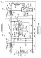
- FIG. 1 is a piping diagram illustrating an overall configuration of a regenerative air conditioner according to an embodiment of the present disclosure.
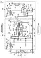
- FIG. 2 is a view corresponding to FIG. 1 for explaining the operation of the simple cooling operation.
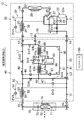
- FIG. 3 is a view corresponding to FIG. 1 for explaining the operation of the cold storage operation.
- FIG. 4 is a view corresponding to FIG. 1 for explaining the operation of the use cooling operation.
- FIG. 5 is a diagram corresponding to FIG. 1 for explaining the operation of the cooling and accumulating operation.
- FIG. 6 is a diagram corresponding to FIG. 1 for explaining the operation of the simple heating operation.
- FIG. 7 is a view corresponding to FIG. 1 for explaining the operation of the heat storage operation.
- FIG. 8 is a view corresponding to FIG.
- FIG. 9 is a view corresponding to FIG. 1 for explaining the heating and heat storage operation (2).
- FIG. 10 is a view corresponding to FIG. 1 for explaining the use heating operation (1).
- FIG. 11 is a view corresponding to FIG. 1 for explaining the use heating operation (2).
- FIG. 12 is a diagram illustrating an example of the relationship between the rotational speed of the compressor and the compressor efficiency.
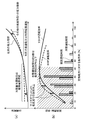
- FIG. 13 is a diagram for explaining the other embodiments 1 and 2, and graphs the power consumption, the efficiency of the regenerative air conditioner, and the operation time with respect to the transition of the load factor with respect to the rated capacity.
- the regenerative air conditioner (10) switches between indoor cooling and heating.
- the heat storage type air conditioner (10) stores the cold heat of the refrigerant in a heat storage medium, and uses this cold heat for cooling.
- the heat storage type air conditioner (10) stores the heat of the refrigerant in a heat storage medium and uses the heat for heating.
- the heat storage type air conditioner (10) includes an outdoor unit (20), a heat storage unit (40), and a plurality of indoor units (70).
- the outdoor unit (20) and the heat storage unit (40) are installed outdoors.
- the plurality of indoor units (70) are installed indoors. In FIG. 1, only one indoor unit (70) is shown for convenience.
- the outdoor unit (20) is provided with an outdoor circuit (21), the heat storage unit (40) is provided with an intermediate circuit (41), and the indoor unit (70) is provided with an indoor circuit (71).
- the outdoor circuit (21) and the intermediate circuit (41) are connected to each other via three connecting pipes (12, 13, 14), and the intermediate circuit (41)
- the indoor circuit (71) is connected to each other via two connecting pipes (15, 16).
- the refrigerant circuit (11) in which the filled refrigerant circulates and the refrigeration cycle is performed is configured.
- the heat storage type air conditioner (10) includes a controller (100) (operation control unit) that controls each device described later.
- the outdoor unit (20) is provided with an outdoor circuit (21) that forms part of the refrigerant circuit (11).
- a compressor (22), an outdoor heat exchanger (23), an outdoor expansion valve (24), and a four-way switching valve (25) are connected to the outdoor circuit (21).
- a first subcooling circuit (30) and an intermediate suction pipe (35) are connected to the outdoor circuit (21).
- the compressor (22) of the present embodiment is a single-stage compressor, and constitutes a compression unit that compresses and discharges refrigerant.
- a motor and a compression mechanism (not shown) are accommodated in the casing (22a).
- the compression mechanism of the present embodiment is composed of a scroll type compression mechanism.
- the compression mechanism can employ various types such as a swing piston type, a rolling piston type, a screw type, and a turbo type.
- a compression chamber is formed between the spiral fixed scroll and the movable scroll, and the refrigerant is compressed by gradually reducing the volume of the compression chamber.
- the motor of the compressor (22) is configured such that the operation frequency is variable by the inverter unit. That is, the compressor (22) is an inverter type compressor having a variable rotation speed (capacity).
- the outdoor heat exchanger (23) is composed of, for example, a cross fin and tube heat exchanger.
- An outdoor fan (26) is provided in the vicinity of the outdoor heat exchanger (23).
- the air conveyed by the outdoor fan (26) and the refrigerant flowing through the outdoor heat exchanger (23) exchange heat.
- an outdoor air temperature sensor (S1) for detecting the temperature of the outdoor air is provided. Note that the outside temperature sensor (S1) is shown only in FIG. 1 for the sake of convenience, and illustration of the other drawings is omitted.
- the outdoor expansion valve (24) is disposed between the liquid side end of the outdoor heat exchanger (23) and the connection end of the communication pipe (12).
- the outdoor expansion valve (24) is composed of, for example, an electronic expansion valve, and adjusts the flow rate of the refrigerant by changing the opening degree.
- the four-way selector valve (25) has first to fourth ports.
- the first port of the four-way switching valve (25) is connected to the discharge pipe (27) of the compressor (22), and the second port of the four-way switching valve (25) is the suction pipe (28) of the compressor (22). It is connected to (low pressure suction part).
- the third port of the four-way selector valve (25) is connected to the gas side end of the outdoor heat exchanger (23), and the fourth port of the four-way selector valve (25) is connected to the connection end of the communication pipe (14). Yes.
- the four-way switching valve (25) includes a state in which the first port and the third port communicate with each other and a state in which the second port and the fourth port communicate with each other (first state indicated by a solid line in FIG. 1), the first port and the fourth port. It is configured to be able to switch between a state in which the ports are in communication and a state in which the second port and the third port are in communication (second state indicated by a broken line in FIG. 1).
- the first subcooling circuit (30) includes a first introduction pipe (31) and a first subcooling heat exchanger (32).
- One end of the first introduction pipe (31) is connected between the outdoor expansion valve (24) and the connection end of the communication pipe (12).
- the other end of the first introduction pipe (31) is connected to the suction pipe (28) of the compressor (22). That is, the first introduction pipe (31) forms a low-pressure introduction pipe that connects the liquid line (L1) and the suction pipe (28) on the low-pressure side of the compressor (22).
- the liquid line (L1) is a flow path extending from the liquid side end of the outdoor heat exchanger (23) to the liquid side end of the indoor heat exchanger (72).
- a first pressure reducing valve (EV1) and a first heat transfer channel (33) are connected to the first introduction pipe (31) in order from one end to the other end.
- the first pressure reducing valve (EV1) is constituted by, for example, an electronic expansion valve, and adjusts the degree of supercooling of the refrigerant at the outlet of the second heat transfer channel (34) by changing the opening thereof.
- the first subcooling heat exchanger (32) constitutes a first heat exchanger that exchanges heat between the refrigerant flowing through the second heat transfer channel (34) and the refrigerant flowing through the first heat transfer channel (33).
- the second heat transfer channel (34) is provided between the outdoor expansion valve (24) and the connection end of the communication pipe (12) in the liquid line (L1) of the refrigerant circuit (11).
- the intermediate suction pipe (35) constitutes an intermediate suction portion for introducing intermediate-pressure refrigerant in the middle of compression of the compression chamber of the compressor (22).
- the start end of the intermediate suction pipe (35) is connected to the connection end of the communication pipe (13), and the end of the intermediate suction pipe (35) is connected to the compression chamber of the compression mechanism of the compressor (22).
- the intermediate suction pipe (35) has an inner pipe part (36) located inside the casing (22a) of the compressor (22).
- the internal pressure of the intermediate suction pipe (35) basically corresponds to an intermediate pressure between the high pressure and the low pressure of the refrigerant circuit (11).
- a first solenoid valve (SV1) and a check valve (CV1) are connected to the intermediate suction pipe (35) in order from the upstream side to the downstream side.
- the first solenoid valve (SV1) is an on-off valve that opens and closes the flow path.
- the check valve (CV1) allows the refrigerant to flow in the direction (arrow direction in FIG. 1) from the main heat storage channel (44) (details will be described later) to the compressor (22). ) To the main heat storage flow path (44).
- the heat storage unit (40) constitutes a relay unit interposed between the outdoor unit (20) and the indoor unit (70).
- the heat storage unit (40) is provided with an intermediate circuit (41) that forms part of the refrigerant circuit (11).
- a main liquid pipe (42), a main gas pipe (43), and a main heat storage flow path (44) are connected to the intermediate circuit (41).
- the second subcooling circuit (50) is connected to the intermediate circuit (41).
- the heat storage unit (40) is provided with a heat storage device (60).
- the main liquid pipe (42) constitutes a part of the liquid line (L1).
- the main liquid pipe (42) connects the connecting end of the connecting pipe (12) and the connecting end of the connecting pipe (15).
- a second solenoid valve (SV2) is connected to the main liquid pipe (42).
- the second solenoid valve (SV2) is an open / close valve that opens and closes the flow path.
- the main gas pipe (43) constitutes a part of the gas line (L2).
- the gas line (L2) is a flow path from the fourth port of the four-way switching valve (25) to the gas side end of the indoor heat exchanger (72).
- the main gas pipe (43) connects the connecting end of the connecting pipe (14) and the connecting end of the connecting pipe (16).
- the main heat storage channel (44) is connected between the main liquid pipe (42) and the main gas pipe (43).
- One end of the main heat storage channel (44) is connected between the connection end of the communication pipe (12) and the second solenoid valve (SV2).
- the expansion valve (45), the heat storage side refrigerant flow path (63b), and the fourth electromagnetic valve (SV4) are connected.
- the third solenoid valve (SV3) and the fourth solenoid valve (SV4) are open / close valves that open and close the flow path.
- the heat storage expansion valve (45) is composed of, for example, an electronic expansion valve, and adjusts the pressure of the refrigerant by changing its opening.
- a first bypass pipe (44a) that bypasses the heat storage expansion valve (45) is connected to the main heat storage flow path (44).
- a fifth electromagnetic valve (SV5) is connected to the first bypass pipe (44a) in parallel with the heat storage expansion valve (45).
- the fifth solenoid valve (SV5) is an open / close valve that opens and closes the flow path.
- a pressure relief valve (RV) is connected to the main heat storage flow path (44) in parallel with the heat storage expansion valve (45).
- the second subcooling circuit (50) has a second introduction pipe (51) and a second subcooling heat exchanger (52).
- One end of the second introduction pipe (51) is connected between the second solenoid valve (SV2) and the connection end of the communication pipe (15).
- the other end of the second introduction pipe (51) is connected to the main gas pipe (43).
- the connection part of the second introduction pipe (51) is located between the connection part of the main heat storage channel (44) and the connection end of the communication pipe (16).
- a second pressure reducing valve (EV2) and a third heat transfer channel (53) are connected to the second introduction pipe (51) in order from one end to the other end.
- the second pressure reducing valve (EV2) is constituted by, for example, an electronic expansion valve, and adjusts the degree of supercooling of the refrigerant at the outlet of the fourth heat transfer channel (54) by changing the opening thereof.
- the second subcooling heat exchanger (52) exchanges heat between the refrigerant flowing through the fourth heat transfer channel (54) and the refrigerant flowing through the third heat transfer channel (53).
- a 4th heat-transfer channel (54) is provided between the connection ends of a 2nd solenoid valve (SV2) and connecting piping (15) among main liquid pipes (42).
- the second subcooling circuit (50) constitutes a supercooler for preventing the refrigerant flowing through the communication pipe (15) from being vaporized and flushed in the use cooling operation and the use cold storage operation, which will be described in detail later.
- An intermediate relay pipe (46), a first branch pipe (47), a second branch pipe (48), and a third branch pipe (49) are connected to the intermediate circuit (41).
- One end of the intermediate relay pipe (46) is connected between the third solenoid valve (SV3) and the preheating side refrigerant flow path (64b) in the main heat storage flow path (44).
- the other end of the intermediate relay pipe (46) is connected to the intermediate suction pipe (35) via the connection pipe (13).
- One end of the first branch pipe (47) is connected between the heat storage side refrigerant flow path (63b) and the fourth electromagnetic valve (SV4) in the main heat storage flow path (44).
- the other end of the first branch pipe (47) is connected between the connection portion of the main heat storage flow path (44) in the main gas pipe (43) and the connection portion of the second introduction pipe (51).
- a third pressure reducing valve (EV3) is connected to the first branch pipe (47).
- the third pressure reducing valve (EV3) is composed of, for example, an electronic expansion valve, and adjusts the pressure of the refrigerant by changing its opening degree.
- the third pressure reducing valve (EV3) is a head that depends on the pressure loss of the communication pipe (16) and the installation conditions of the indoor unit (70) and the outdoor unit (20) when the indoor heat exchanger (72) is an evaporator. Due to the difference, the opening degree is adjusted so that the pressure in the heat storage heat exchanger (63) does not become excessively low due to the difference in evaporation pressure between the indoor heat exchanger (72) and the gas pipe (41). Is done.
- the second branch pipe (48) and the third branch pipe (49) are connected in parallel between the main liquid pipe (42) and the main heat storage flow path (44).
- One ends of the second branch pipe (48) and the third branch pipe (49) are connected between the heat storage side refrigerant flow path (63b) and the fourth solenoid valve (SV4) in the main heat storage flow path (44).
- the other ends of the second branch pipe (48) and the third branch pipe (49) are connected between the second solenoid valve (SV2) in the main liquid pipe (42) and the connection portion of the second introduction pipe (51). Is done.
- a fourth pressure reducing valve (EV4) is connected to the second branch pipe (48).
- the fourth pressure reducing valve (EV4) is constituted by, for example, an electronic expansion valve, and adjusts the pressure of the refrigerant by changing its opening degree.
- a sixth solenoid valve (SV6) is connected to the third branch pipe (49).
- the sixth solenoid valve (SV6) is an open / close valve that opens and closes the flow path.
- the heat storage device (60) constitutes a heat storage unit that exchanges heat between the refrigerant of the refrigerant circuit (11) and the heat storage medium.
- the heat storage device (60) includes a heat storage circuit (61) and a heat storage tank (62) connected to the heat storage circuit (61).
- the heat storage device (60) includes a heat storage heat exchanger (63) and a preheating heat exchanger (64).
- the heat storage circuit (61) is a closed circuit in which the filled heat storage medium circulates.
- the heat storage tank (62) is a hollow cylindrical container.
- the heat storage tank (62) may be an open container.
- a heat storage medium is stored in the heat storage tank (62).
- An outflow pipe (65) (outflow portion) through which the heat storage medium in the heat storage tank (62) flows out is connected to the upper part of the heat storage tank (62).
- An inflow pipe (66) (inflow part) for allowing a heat storage medium outside the heat storage tank (62) to flow into the heat storage tank (62) is connected to the lower part of the heat storage tank (62). That is, in the heat storage tank (62), the connection part of the outflow pipe (65) is located higher than the connection part of the W inflow pipe (66).
- the preheat side heat storage channel (64a), the pump (67), and the heat storage side heat storage channel (63a) are connected to the heat storage circuit (61) in order from the outflow pipe (65) to the inflow pipe (66). Yes.
- the preheating heat exchanger (64) exchanges heat between the heat storage medium flowing through the preheating side heat storage channel (64a) and the refrigerant flowing through the preheating side refrigerant channel (64b).
- the heat storage heat exchanger (63) exchanges heat between the heat storage medium flowing through the heat storage side heat storage flow path (63a) and the refrigerant flowing through the heat storage side refrigerant flow path (63b).
- the pump (67) circulates the heat storage medium of the heat storage circuit (61).
- a heat storage medium temperature sensor (S2) heat storage medium temperature detection unit
- the heat storage medium temperature sensor (S2) is provided at a position for detecting the temperature of the heat storage medium in the inflow pipe (66).
- the heat storage medium temperature sensor (S2) also serves as an accumulation detection unit that detects the start of accumulation of clathrate hydrate crystals in the heat storage circuit (61).
- the position of the heat storage medium temperature sensor (S2) is not limited to this, and may be provided at another position of the heat storage circuit (61). Note that the heat storage medium temperature sensor (S2) is shown only in FIG. 1 for the sake of convenience, and the other figures are omitted.
- Heat storage medium The heat storage medium filled in the heat storage circuit (61) will be described in detail.
- a heat storage material in which clathrate hydrate is generated by cooling that is, a fluid heat storage material is employed.
- Specific examples of the heat storage medium include tetra nbutylammonium bromide (TBAB) aqueous solution, tetramethylolethane (TME) aqueous solution, paraffinic slurry and the like containing tetra nbutylammonium bromide. .
- an aqueous solution of tetra-n-butylammonium bromide maintains the state of the aqueous solution even in a supercooled state in which the temperature of the aqueous solution is lower than the hydrate formation temperature after being stably cooled.
- the supercooled solution transitions to a solution containing clathrate hydrate (ie, slurry). That is, the aqueous solution of tetra-n-butylammonium bromide eliminates the supercooled state, and clathrate hydrate (hydrate crystal) composed of tetra-n-butylammonium bromide and water molecules is generated, and the viscosity is relatively low. It becomes a high slurry state.
- the supercooled state refers to a state where the clathrate hydrate is not generated and the state of the solution is maintained even when the heat storage medium becomes a temperature lower than the hydrate generation temperature.
- the aqueous solution of tetra-n-butylammonium bromide in a slurry state is heated, the temperature of the aqueous solution becomes higher than the hydrate formation temperature, the clathrate hydrate melts and the fluidity is relatively high. It becomes a liquid state (solution).
- a tetra nbutylammonium bromide aqueous solution containing tetra nbutylammonium bromide is employed as the heat storage medium.
- the heat storage medium is preferably a medium having a concentration near the harmonic concentration.
- the harmonic concentration is about 40%.
- the hydrate formation temperature of the aqueous solution of tetra-n-butylammonium bromide is about 12 ° C.
- the indoor units (70) are each provided with an indoor circuit (71) that forms part of the refrigerant circuit (11).
- the plurality of indoor circuits (71) are connected in parallel between the communication pipe (15) (liquid pipe) and the communication pipe (16) (gas pipe).
- the plurality of indoor circuits (71) and the main heat storage flow path (44) described above are connected in parallel between the liquid line (L1) and the gas line (L2).
- An indoor heat exchanger (72) and an indoor expansion valve (73) are connected to each indoor circuit (71) in order from the gas side end to the liquid side end.
- the indoor heat exchanger (72) is composed of, for example, a cross fin and tube heat exchanger.
- An indoor fan (74) is provided in the vicinity of the indoor heat exchanger (72). In the indoor heat exchanger (72), the air conveyed by the indoor fan (74) and the refrigerant flowing through the outdoor heat exchanger (23) exchange heat.
- the indoor circuit (71) is provided with a refrigerant temperature sensor (S3) at the liquid side end of the indoor heat exchanger (72).
- the refrigerant temperature sensor (S3) satisfies a condition indicating that the temperature of the refrigerant condensed in the indoor heat exchanger (72) is high or a condition indicating that the temperature of the refrigerant is low in the simple heating operation described later in detail. Used to determine whether or not to do.
- an air temperature detection sensor that detects the temperature of the blown air that has exchanged heat with the refrigerant in the indoor heat exchanger (72) may be used. Note that the refrigerant temperature sensor (S3) is shown only in FIG. 1 for convenience, and illustration of other drawings is omitted.
- the indoor expansion valve (73) is disposed between the liquid side end of the indoor heat exchanger (72) and the connection end of the communication pipe (15).
- the indoor expansion valve (73) is composed of, for example, an electronic expansion valve, and adjusts the flow rate of the refrigerant by changing the opening thereof.
- the controller (100) constitutes an operation control unit that controls each device. Specifically, the controller (100) switches ON / OFF of the compressor (22), switches the state of the four-way switching valve (25), switches opening / closing of each solenoid valve (SV1-6), and each expansion valve ( 24, 45, 73) and opening of the pressure reducing valve (EV1-4), ON / OFF switching of each fan (26, 74), ON / OFF switching of the pump (67), and the like.
- the regenerative air conditioner (10) is provided with various sensors (not shown). The controller (100) controls each device described above based on these detection values.
- the operation of the regenerative air conditioner (10) according to this embodiment will be described.
- the heat storage type air conditioner (10) performs simple cooling operation, cold storage operation, use cooling operation, cooling cooling storage operation, simple heating operation, heat storage operation, heating heat storage operation, and use heating operation.
- the controller (100) controls each device so as to switch each of these operations.
- the compressor (22), the outdoor fan (26), and the indoor fan (74) operate.
- the heat storage device (60) does not operate because the pump (67) is stopped.
- the outdoor heat exchanger (23) serves as a condenser
- the first subcooling heat exchanger (32) serves as a supercooler
- the indoor heat exchanger (72) serves as an evaporator.
- a refrigeration cycle is performed.
- the low pressure side gas line (L2) communicates with the main heat storage flow path (44). Thereby, the liquid pool in the main heat storage flow path (44) can be avoided.
- the refrigerant discharged from the compressor (22) is condensed in the outdoor heat exchanger (23). Most of the condensed refrigerant flows through the second heat transfer channel (34), and the rest flows through the first heat transfer channel (33) after being depressurized by the first pressure reducing valve (EV1).
- the refrigerant in the second heat transfer channel (34) is cooled by the refrigerant in the first heat transfer channel (33).
- the refrigerant flowing into the liquid line (L1) is depressurized by the indoor expansion valve (73) and then evaporated by the indoor heat exchanger (72).
- the refrigerant flowing through the gas line (L2) joins with the refrigerant flowing into the first introduction pipe (31) and is sucked into the compressor (22).
- the heat storage device (60) In the cold storage operation, the heat storage device (60) is operated, and cold heat is stored in the heat storage medium of the heat storage tank (62).
- the four-way switching valve (25) is in the first state, and the second solenoid valve (SV2), the third solenoid valve (SV6) of the first solenoid valve (SV1) to the sixth solenoid valve (SV6) SV3) and 4th solenoid valve (SV4) are opened, and the rest are closed.
- the first pressure reducing valve (EV1), the second pressure reducing valve (EV2), the third pressure reducing valve (EV3), and the fourth pressure reducing valve (EV4) are fully closed, and the outdoor expansion valve (24) is fully opened to store heat.
- the opening degree of the expansion valve (45) is appropriately adjusted.
- the compressor (22) and the outdoor fan (26) operate, and the indoor fan (74) stops.
- the heat storage device (60) operates when the pump (67) is in operation.
- the outdoor heat exchanger (23) serves as a condenser
- the preheating heat exchanger (64) serves as a radiator (refrigerant cooler)
- the heat storage heat exchanger (63) evaporates.
- a refrigeration cycle is performed.
- surplus refrigerant can be held in the flow path extending from the high-pressure liquid line (L1) to the indoor unit (70).
- the refrigerant discharged from the compressor (22) is condensed in the outdoor heat exchanger (23).
- the condensed refrigerant flows through the preheating side refrigerant flow path (64b) of the main heat storage flow path (44).
- the preheating heat exchanger (64) the heat storage medium is heated by the refrigerant.
- the clathrate hydrate core (fine crystals) flowing out of the heat storage tank (62) is melted.
- the refrigerant cooled in the preheating side refrigerant flow path (64b) is depressurized by the preheating heat exchanger (64) and then flows through the heat storage side refrigerant flow path (63b).
- the heat storage medium is cooled by the refrigerant and evaporated.
- the refrigerant flowing into the gas line (L2) from the main heat storage channel (44) is sucked into the compressor (22).
- the heat storage tank (62) stores the heat storage medium cooled by the heat storage heat exchanger (63).
- the heat storage device (60) is operated, and the cold energy of the heat storage medium stored in the heat storage tank (62) is used for indoor cooling.
- the four-way switching valve (25) is set to the first state among the first solenoid valve (SV1) to the sixth solenoid valve (SV6), the third solenoid valve (SV3), the fifth solenoid valve ( SV5) and the sixth solenoid valve (SV6) are opened, and the rest are closed.
- the first pressure reducing valve (EV1) and the fourth pressure reducing valve (EV4) are fully closed, the outdoor expansion valve (24) is fully opened, and the opening degrees of the second pressure reducing valve (EV2) and the indoor expansion valve (73) are Adjust as appropriate.
- the compressor (22), the outdoor fan (26), and the indoor fan (74) operate.
- the heat storage device (60) operates when the pump (67) is in operation.
- the outdoor heat exchanger (23) is a condenser, and the preheating heat exchanger (64), the heat storage heat exchanger (63), and the second subcooling heat exchanger ( A refrigeration cycle is performed in which 52) becomes a radiator (refrigerant cooler) and the indoor heat exchanger (72) becomes an evaporator.
- the refrigerant discharged from the compressor (22) is condensed in the outdoor heat exchanger (23).
- the condensed refrigerant is cooled by the preheat heat exchanger (64) of the main heat storage flow path (44), passes through the first bypass pipe (44a), and further cooled by the heat storage heat exchanger (63).
- the Most of the refrigerant flowing through the main heat storage flow path (44) and the third branch pipe (49) and flowing into the liquid line (L1) flows through the fourth heat transfer flow path (54), and the rest flows through the second pressure reducing valve ( After being depressurized by EV2), it flows through the third heat transfer channel (53).
- the refrigerant flowing through the fourth heat transfer channel (54) is cooled by the refrigerant in the third heat transfer channel (53).
- the refrigerant cooled by the second subcooling heat exchanger (52) is depressurized by the indoor expansion valve (73) and then evaporated by the indoor heat exchanger (72).
- the refrigerant flowing through the gas line (L2) merges with the refrigerant that has flowed out of the second introduction pipe (51), and is sucked into the compressor (22).
- the heat storage device (60) operates to store the cold energy in the heat storage medium, and the indoor unit (70) cools the room.
- the four-way switching valve (25) is in the first state, and the second solenoid valve (SV2) and the third solenoid valve among the first solenoid valve (SV1) to the sixth solenoid valve (SV6). (SV3) and the fourth solenoid valve (SV4) are opened, and the rest are closed.
- the first pressure reducing valve (EV1), the third pressure reducing valve (EV3), and the fourth pressure reducing valve (EV4) are fully closed, the outdoor expansion valve (24) is fully open, the second pressure reducing valve (EV2), and heat storage
- the opening degrees of the expansion valve (45) and the indoor expansion valve (73) are appropriately adjusted.
- the compressor (22), the outdoor fan (26) and the indoor fan (74) operate.
- the heat storage device (60) operates when the pump (67) is in operation.
- the outdoor heat exchanger (23) serves as a condenser
- the preheating heat exchanger (64) and the second subcooling heat exchanger (52) serve as a radiator (refrigerant cooler).
- the heat storage heat exchanger (63) and the indoor heat exchanger (72) serve as an evaporator.
- the refrigerant discharged from the compressor (22) is condensed in the outdoor heat exchanger (23).
- the condensed refrigerant flows through the second heat transfer channel (34) and is divided into the main heat storage channel (44) and the main liquid pipe (42).
- the refrigerant in the main heat storage flow path (44) is cooled by the heat storage medium of the preheating heat exchanger (64) and depressurized by the heat storage expansion valve (45).
- Most of the refrigerant in the main liquid pipe (42) flows through the fourth heat transfer channel (54), and the rest flows through the third heat transfer channel (53) after being depressurized by the second pressure reducing valve (EV2).
- the refrigerant flowing through the fourth heat transfer channel (54) is cooled by the refrigerant in the third heat transfer channel (53).
- the refrigerant cooled by the second subcooling heat exchanger (52) is depressurized by the indoor expansion valve (73) and then evaporated by the indoor heat exchanger (72).
- the refrigerant flowing through the gas line (L2) merges with the refrigerant that has flowed out of the second introduction pipe (51), and is sucked into the compressor (22).
- the compressor (22), the outdoor fan (26), and the indoor fan (74) operate.
- the heat storage device (60) does not operate because the pump (67) is stopped.
- a refrigeration cycle is performed in which the indoor heat exchanger (72) serves as a condenser and the outdoor heat exchanger (23) serves as an evaporator.
- the indoor expansion valve (73) controls the degree of supercooling of the outlet refrigerant of the indoor heat exchanger (72).
- the refrigerant discharged from the compressor (22) flows through the gas line (L2) and condenses in the indoor heat exchanger (72).
- the refrigerant flowing out to the liquid line (L1) is decompressed by the outdoor expansion valve (24), evaporated by the outdoor heat exchanger (23), and sucked into the compressor (22).
- the heat storage medium storing the heat is stored in the heat storage tank (62).
- the four-way switching valve (25) is in the second state, and the third solenoid valve (SV3), the fourth solenoid valve (SV6) among the first solenoid valve (SV1) to the sixth solenoid valve (SV6) SV4) and the fifth solenoid valve (SV5) are opened, and the rest are closed.
- the first pressure reducing valve (EV1), the second pressure reducing valve (EV2), the third pressure reducing valve (EV3), the fourth pressure reducing valve (EV4), and the indoor expansion valve (73) are fully closed, and the outdoor expansion valve (24 ) Is adjusted as appropriate.
- the compressor (22) and the outdoor fan (26) operate, and the indoor fan (74) stops.
- the heat storage device (60) operates when the pump (67) is in operation.
- a refrigeration cycle is performed in which the heat storage heat exchanger (63) and the preheating heat exchanger (64) serve as a condenser and the outdoor heat exchanger (23) serves as an evaporator.
- the refrigerant discharged from the compressor (22) flows through the gas line (L2), dissipates heat in the heat storage heat exchanger (63), passes through the second bypass pipe (44a), and then passes through the second heat exchanger (44a). 64) further dissipate heat.
- the refrigerant flowing out of the main heat storage flow path (44) is decompressed by the outdoor expansion valve (24), evaporated by the outdoor heat exchanger (23), and sucked into the compressor (22).
- the heat storage tank (62) stores the heat storage medium heated by the heat storage heat exchanger (63) and the preheating heat exchanger (64).
- Heating heat storage operation In the heating and heat storage operation, the heat storage device (60) operates to store the heat in the heat storage tank (62), and the indoor unit (70) heats the room.
- the heating heat storage operation is roughly classified into a first heating heat storage operation (hereinafter referred to as heating heat storage operation (1)) and a second heating heat storage operation (hereinafter referred to as heating heat storage operation (2)).
- the four-way switching valve (25) is set to the second state, and the third solenoid valve (SV3) of the first solenoid valve (SV1) to the sixth solenoid valve (SV6), 5 solenoid valve (SV5) and 6th solenoid valve (SV6) are opened, and the rest are closed.
- the first pressure reducing valve (EV1), the second pressure reducing valve (EV2), the third pressure reducing valve (EV3), the fourth pressure reducing valve (EV4), and the heat storage expansion valve (45) are fully closed, and the indoor expansion valve ( 73) and the opening degree of the outdoor expansion valve (24) are appropriately adjusted.
- the compressor (22), the outdoor fan (26), and the indoor fan (74) operate.
- the heat storage device (60) operates when the pump (67) is in operation.
- the indoor heat exchanger (72) serves as a condenser
- the heat storage heat exchanger (63) and the preheating heat exchanger (64) serve as a radiator
- the outdoor heat exchanger (23 ) Is used as an evaporator.
- the refrigerant discharged from the compressor (22) flows through the gas line (L2), and the entire amount flows through the indoor heat exchanger (72).
- the indoor heat exchanger (72) the refrigerant dissipates heat to the indoor air and condenses.
- the entire amount of the refrigerant condensed in the indoor heat exchanger (72) flows through the third branch pipe (49), and then flows through the heat storage heat exchanger (63).
- the heat storage heat exchanger (63) the refrigerant dissipates heat to the heat storage medium, and the heat storage medium is heated.
- the refrigerant that has flowed through the heat storage heat exchanger (63) further dissipates heat to the heat storage medium in the preheating heat exchanger (64), and flows through the liquid line (L1). This refrigerant evaporates in the outdoor heat exchanger (23) and is sucked into the compressor (22).
- the four-way switching valve (25) is set to the second state, and the second solenoid valve (SV2), the second solenoid valve (SV2) among the first solenoid valve (SV1) to the sixth solenoid valve (SV6) 3 solenoid valve (SV3), 4th solenoid valve (SV4), 5th solenoid valve (SV5) are opened, and the rest are closed.
- the first pressure reducing valve (EV1), the second pressure reducing valve (EV2), the third pressure reducing valve (EV3), and the fourth pressure reducing valve (EV4) are fully closed, and the indoor expansion valve (73) and the outdoor expansion valve (24 ) Is adjusted as appropriate.
- the compressor (22), the outdoor fan (26), and the indoor fan (74) operate.
- the heat storage device (60) operates when the pump (67) is in operation.
- a refrigeration cycle is performed in which the indoor heat exchanger (72) and the heat storage heat exchanger (63) serve as a condenser and the outdoor heat exchanger (23) serves as an evaporator.
- the refrigerant discharged from the compressor (22) flows through the gas line (L2), a part flows through the indoor heat exchanger (72), and the rest flows through the main heat storage channel (44).
- the indoor heat exchanger (72) the refrigerant dissipates heat to the indoor air and condenses.
- the refrigerant condensed in the indoor heat exchanger (72) flows through the main liquid pipe (42).
- the refrigerant in the main heat storage flow path (44) dissipates heat to the heat storage medium and condenses in the heat storage heat exchanger (63). Since this refrigerant is a high-temperature and high-pressure gas refrigerant, the temperature difference between the refrigerant and the heat storage medium becomes large, and heat can be reliably imparted to the heat storage medium.
- the refrigerant condensed in the heat storage heat exchanger (63) merges with the refrigerant flowing through the main liquid pipe (42) and is decompressed by the outdoor expansion valve (24). The decompressed refrigerant evaporates in the outdoor heat exchanger (23) and is sucked into the compressor (22).
- the high-temperature and high-pressure gas refrigerant discharged from the compressor (22) is parallel to both the indoor heat exchanger (72) and the heat storage heat exchanger (63). To condense on each. As a result, it is possible to reliably impart warm heat to the heat storage medium while continuing indoor heating.
- Utilization heating operation In the utilization heating operation, the heat storage device (60) is operated, and the heat of the heat storage medium stored in the heat storage tank (62) is used as the evaporation heat of the low-pressure refrigerant. Thereby, reduction of heating load is achieved.
- the utilization heating operation is roughly classified into a first utilization heating operation (hereinafter referred to as utilization heating operation (1)) and a second utilization heating operation (hereinafter referred to as utilization heating operation (2)).
- the utilization heating operation (1) is a difference (MP ⁇ LP) between the pressure (MP) of the refrigerant evaporating in the heat storage heat exchanger (63) and the pressure (LP) of the refrigerant evaporating in the outdoor heat exchanger (23). ) Is executed under such a condition that becomes relatively small. For example, this condition corresponds to a case in which the temperature of the heat storage medium of the heat storage circuit (61) of the heat storage device (60) is relatively low while the outside air temperature is relatively high in winter.
- the four-way switching valve (25) is in the second state, and the third solenoid valve (SV3) and the sixth solenoid valve (SV6) out of the first solenoid valve (SV1) to the sixth solenoid valve (SV6).
- 5 Solenoid valve (SV5) is opened and the rest is closed.
- the first pressure reducing valve (EV1) and the outdoor expansion valve (24) are fully opened, the second pressure reducing valve (EV2) and the third pressure reducing valve (EV3) are fully closed, the fourth pressure reducing valve (EV4) and the indoor expansion valve
- the opening degree of the valve (73) is adjusted as appropriate.
- the compressor (22) and the indoor fan (74) operate, and the outdoor fan (26) stops.
- the heat storage device (60) operates when the pump (67) is in operation.
- a refrigeration cycle is performed in which the indoor heat exchanger (72) serves as a condenser and the heat storage heat exchanger (63) serves as an evaporator.
- the refrigerant discharged from the compressor (22) flows through the gas line (L2) and condenses in the indoor heat exchanger (72).
- the entire amount of the refrigerant that has flowed out to the liquid line (L1) flows into the second branch pipe (48).
- the refrigerant is decompressed to a low pressure by the fourth pressure reducing valve (EV4).
- the decompressed refrigerant flows through the heat storage side refrigerant flow path (63b) of the heat storage heat exchanger (63), absorbs heat from the heat storage medium, and evaporates.
- the refrigerant evaporated in the heat storage heat exchanger (63) passes through the first bypass pipe (44a), flows through the preheating side refrigerant flow path (64b) of the preheating heat exchanger (64), and absorbs heat from the heat storage medium. Evaporate further.
- This refrigerant flows through the main heat storage channel (44) and is divided into the first introduction pipe (31) and the outdoor heat exchanger (23). These refrigerants merge through the suction pipe (28) and are sucked into the compressor (22). For this reason, the pressure loss of a refrigerant
- coolant can be reduced and the motive power of a compressor (22) can be reduced.
- the refrigerant flowing through the first introduction pipe (31) flows through the first subcooling heat exchanger (32).
- the first subcooling heat exchanger (32) is not an air heat exchanger, heat loss is also reduced. Few. Moreover, since the outdoor fan (26) is in a stopped state, even if the refrigerant flows through the outdoor heat exchanger (23), there is little heat loss. Thus, in use heating operation (1), the pressure loss and heat loss of the low-pressure gas refrigerant can be reduced. Further, since the first introduction pipe (31) also serves as a low-pressure injection pipe for supercooling the refrigerant, the number of pipes can be reduced.
- the outdoor expansion valve (24) of the first pressure reducing valve (EV1) and the outdoor expansion valve (24) is fully closed, and the low pressure gas refrigerant is supplied to the first introduction pipe (31). You can only flush it.
- the first pressure reducing valve (EV1) of the first pressure reducing valve (EV1) and the outdoor expansion valve (24) may be fully closed, and the low pressure gas refrigerant may flow only to the outdoor heat exchanger (23).
- the utilization heating operation (2) is the difference between the pressure (MP) of the refrigerant evaporating in the heat storage heat exchanger (63) and the pressure (LP) of the refrigerant evaporating in the outdoor heat exchanger (23) (MP-LP ) Is performed under conditions that are relatively large. For example, in the winter season, the outside air temperature is relatively low, while the temperature of the heat storage medium in the heat storage circuit (61) of the heat storage device (60) is relatively high.
- the four-way switching valve (25) is in the second state, and the first solenoid valve (SV1) to the sixth solenoid valve (SV6) are switched from the first solenoid valve (SV1) to the sixth solenoid valve (SV6).
- 2 solenoid valve (SV2) and 5th solenoid valve (SV5) are opened, and the rest are closed.
- the first pressure reducing valve (EV1), the second pressure reducing valve (EV2), and the third pressure reducing valve (EV3) are fully closed, and the fourth pressure reducing valve (EV4), the indoor expansion valve (73), and the outdoor expansion valve ( The opening degree of 24) is adjusted as appropriate.
- the compressor (22), the outdoor fan (26), and the indoor fan (74) operate.
- the heat storage device (60) operates when the pump (67) is in operation.
- the indoor heat exchanger (72) becomes a condenser, and the heat storage heat exchanger (63), the preheating heat exchanger (64), and the outdoor heat exchanger (23) A refrigeration cycle that serves as an evaporator is performed.
- the refrigerant discharged from the compressor (22) flows through the gas line (L2) and condenses in the indoor heat exchanger (72).
- the refrigerant flowing out to the liquid line (L1) is divided into the second branch pipe (48) and the main liquid pipe (42).
- the refrigerant in the second branch pipe (48) is reduced to an intermediate pressure (intermediate pressure between the high pressure and low pressure of the refrigerant circuit (11)) by the fourth pressure reducing valve (EV4), and the main heat storage flow path.
- the refrigerant in the main heat storage flow path (44) is heated and evaporated by the heat storage heat exchanger (63) and the preheating heat exchanger (64).
- the evaporated refrigerant flows through the intermediate relay pipe (46), the communication pipe (13), and the intermediate suction pipe (35) in this order, and is sucked into the compression chamber in the middle of compression of the compressor (22).
- the refrigerant in the main liquid pipe (42) is depressurized by the outdoor expansion valve (24), evaporated by the outdoor heat exchanger (23), and sucked into the suction pipe (28) of the compressor (22).
- the low-pressure refrigerant sucked from the suction pipe (28) is compressed to the intermediate pressure, and then mixed with the intermediate-pressure refrigerant sucked from the intermediate suction pipe (35) to reach the high pressure. Compressed.
- the heat storage heat exchanger (63) The pressure difference (MP-LP) between the refrigerant evaporation pressure MP and the refrigerant evaporation pressure LP in the outdoor heat exchanger (23) becomes relatively large. For this reason, during the compression of the compression chamber of the compressor (22), it is possible to suppress the internal pressure of the compression chamber from becoming larger than the pressure of the refrigerant introduced from the intermediate suction pipe (35), and the refrigerant in the intermediate suction pipe (35) Can be reliably introduced into the compression chamber.
- the intermediate suction pipe (35) is provided with a check valve (CV1) that prohibits backflow from the compressor (22) to the main heat storage flow path (44). For this reason, even if the pressure MP of the refrigerant flowing out of the intermediate suction pipe (35) becomes lower than the internal pressure of the compression chamber in the middle of compression, the refrigerant in the compression chamber flows back through the intermediate suction pipe (35). There is no.
- the check valve (CV1) may be provided in the inner pipe portion (36) located in the casing (22a) of the compressor (22) in the intermediate suction pipe (35).
- the refrigerant when the refrigerant is compressed under a condition where the MP-LP is relatively large, the total work required to compress the refrigerant to a high pressure by the compressor (22) is reduced. As a result, in the use heating operation (2), it is possible to perform heating with high energy saving performance while collecting the heat of the heat storage medium in the refrigerant.
- the controller (100) calculates the outside temperature To detected by the outside temperature sensor (S1) (see FIG. 1) and the predetermined temperature Ta. Compare. When the detected outside temperature To is equal to or higher than the predetermined temperature Ta, it is determined that the first condition is satisfied, and the first operation is executed.
- the first operation is that when the temperature of the heat storage medium is higher than the hydrate generation temperature in the use heating operation (1) or the use heating operation (2), the heat storage medium operates the heat storage heat exchanger (63). It is the driving
- the sensible heat of the heat storage medium having a relatively high temperature is applied to the refrigerant through the heat storage heat exchanger (63) and the preheating heat exchanger (64). Therefore, even if the heat storage medium and the refrigerant exchange heat, the evaporation pressure can be maintained relatively high, and the heating efficiency can be improved.
- the outdoor temperature To is high and the evaporation pressure of the low-pressure refrigerant in the outdoor heat exchanger (23) is also high, so the first operation is continued and the heat storage medium of the heat storage circuit (61)
- the evaporation pressure in the heat storage circuit (61) also decreases, and the heating efficiency does not improve even if the first operation is continued.
- the controller (100) controls each device to end the first operation and execute the simple heating operation.
- the reference temperature Tb is a predetermined temperature equal to or higher than the hydrate formation temperature (for example, 12 ° C.) of the heat storage medium.
- the pump (67) stops and the refrigerant does not flow through the heat storage heat exchanger (63). Therefore, the heat storage medium is not further cooled by the refrigerant, and the temperature of the heat storage medium does not become lower than the hydrate formation temperature.
- the heat storage circuit (61) the clathrate hydrate can be prevented from crystallizing and accumulating in the pipe, and the heat storage circuit (61) can be reliably prevented from being blocked. Moreover, since the indoor heating is continued by shifting to the simple heating operation, the comfort in the room is not impaired.
- the second operation is an operation in which the heat storage medium continues to heat the refrigerant through the heat storage heat exchanger (63) even when the temperature of the heat storage medium becomes lower than the hydrate formation temperature. That is, in the second operation, it can be said that both sensible heat and latent heat stored in the heat storage medium are used for heating.
- the latent heat of the heat storage medium having a relatively low temperature is applied to the refrigerant through the heat storage heat exchanger (63) and the preheating heat exchanger (68).
- the outside air temperature To is low and the evaporation pressure of the low-pressure refrigerant in the outdoor heat exchanger (23) is also low. Therefore, by exchanging heat between the heat storage medium and the refrigerant, the evaporation pressure can be increased and the heating efficiency can be improved.
- the temperature of the heat storage medium of the heat storage circuit (61) gradually decreases and becomes lower than the hydrate generation temperature.
- the heat storage circuit (61) clathrate hydrate may be generated and hydrate crystals may accumulate in the pipe. Therefore, in the heat storage device (60), the start of accumulation of such clathrate hydrate crystals is detected by the heat storage medium temperature sensor (S2).
- the controller (100) determines that accumulation of clathrate hydrate crystals starts when the temperature of the heat storage medium detected by the heat storage medium temperature sensor (S2) rises and changes.
- a flow rate detection unit that detects the circulation amount of the heat storage medium of the heat storage circuit (61) may be employed as the accumulation detection unit that detects the start of accumulation of clathrate hydrate crystals. That is, when the circulation amount of the heat storage medium of the heat storage circuit (61) detected by the flow rate detection unit becomes lower than a predetermined value, it may be detected that the accumulation of clathrate hydrate crystals starts.
- the controller (100) stops the second operation and executes the heating and heat storage operation. Specifically, when the start of accumulation of clathrate hydrate crystals is detected, the controller (100) satisfies the condition indicating that the temperature of the refrigerant condensed in the indoor heat exchanger (72) is high. Determine whether or not.
- the controller (100) causes the first heating / heat storage operation (heating / heat storage operation (1)) to be executed.
- the heating and heat storage operation (1) in which the entire amount of the refrigerant compressed by the compressor (22) flows through the indoor heat exchanger (72) and the heat storage heat exchanger (63) in sequence is executed.
- the heat storage medium can be sufficiently heated by this refrigerant, and indoor heating can be performed. It can be done continuously.
- the determination unit of the controller (100) determines that the condition indicating that the temperature of the refrigerant condensed in the indoor heat exchanger (72) is high is not satisfied. Then, as shown in FIG. 9, the controller (100) executes the second heating heat storage operation (heating heat storage operation (2)). As a result, the refrigerant compressed by the compressor (22) is divided into both the indoor heat exchanger (72) and the heat storage heat exchanger (63), and evaporates in each. As a result, the temperature of the heat storage medium can be reliably raised while continuing indoor heating.
- FIG. 12 shows an example of the relationship between the rotational speed (rps) of the compressor and the compressor efficiency (%).
- the compressor efficiency is highest when the rotational speed is around R.
- the compressor efficiency gradually decreases, and becomes the lowest at the rotational speed Rmin.
- the compressor efficiency is lowered, and the rotational speed Rmax is lower than the case of R.
- the air conditioning capacity of the regenerative air conditioner (10) is controlled by adjusting the rotational speed of the compressor (22). For this reason, if the indoor air conditioning load (cooling load or heating load) is reduced during operation of the regenerative air conditioner (10), the air conditioning capacity of the regenerative air conditioner (10) is reduced according to the indoor air conditioning load. Therefore, the rotational speed of the compressor (22) is reduced.
- the compressor (22) is conventionally stopped.
- the compressor (22) is conventionally stopped.
- the indoor temperature is prevented from becoming too low or too high.
- it is desirable to avoid the on / off operation because it causes an increase in power consumption and a decrease in comfort due to the air conditioning being turned on / off.
- the lower reference value R1 is set to a value larger than Rmin and smaller than R. Further, it is desirable that the lower reference value R1 is set to a value slightly larger than Rmin.
- the controller (100) rotates the compressor (22) so that the low pressure of the refrigeration cycle (that is, the pressure of the refrigerant sucked into the compressor) becomes a predetermined target value. Adjust the speed. For this reason, when the simple cooling operation is switched to the cooling storage operation, it is necessary to increase the rotational speed of the compressor (22) in order to reduce the low pressure of the refrigeration cycle to the target value.
- the controller (100) of this embodiment reduces the rotational speed of the compressor (22) to the lower reference value R1 during the simple cooling operation, and the compressor (22) operates at an inefficient rotational speed.
- the operation of the regenerative air conditioner (10) is switched from the simple cooling operation to the cooling storage operation, and the rotational speed of the compressor (22) is increased.
- the rotational speed of the compressor (22) becomes higher than the lower reference value R1, and the efficiency of the compressor (22) is improved.
- the controller (100) of the present embodiment simplifies the operation of the regenerative air conditioner (10) when the rotational speed of the compressor (22) decreases to the lower reference value R1 during the simple cooling operation. Switch from cooling operation to cooling storage operation. In this way, it becomes possible to cool the room using only a part of the cold heat obtained by the refrigeration cycle, and the indoor air in the indoor heat exchanger (72) while the compressor (22) continues to operate. It is possible to reduce the cooling heat used for cooling the air to an amount commensurate with the indoor cooling load. Therefore, according to the present embodiment, the indoor comfort is kept high by avoiding the on / off operation of the compressor (22) even when the indoor cooling load is very small.
- the lower reference value R1 for switching from the simple cooling operation to the cooling / storage operation is determined from the relationship between the rotational speed and the compressor efficiency as shown in FIG. 12, the rotational speed of the compressor (22) for performing cold storage, and the like Is done.
- the amount of cold stored in the heat storage section (60) may be an element that determines the lower reference value.
- the rotation speed of the compressor (22) reaches the upper reference value R2 during the cooling / storage operation, the rotation speed of the compressor (22) is decreased by switching from the cooling / storage operation to the simple cooling operation.
- the upper reference value R2 is set to a value larger than R and smaller than Rmax.
- the compressor efficiency decreases.
- the compressor efficiency can be increased by switching from the cooling / storage operation to the simple cooling operation.
- the power consumption increases as the rotational speed of the compressor (22) increases. Also from this point, when the rotational speed exceeds a predetermined value, it is desirable to switch from the cooling / storage operation to the simple cooling operation.
- the upper reference value R2 is determined from the relationship between the rotational speed and the compressor efficiency, the rotational speed of the compressor (22) for performing cold storage, and the like.
- At least a certain amount of cooling is required to store the heat in the heat storage section (60), and the amount of increase in rotational speed when switching from the simple cooling operation to the cooling storage operation generates at least the above-mentioned certain amount of cooling. It must be the value of the rotation speed that can be made to.
- the heat storage section (60) may be designed so that cold storage can be performed using cold heat that can be generated at the minimum rotational speed of the compressor (22).
- the heat storage section (60) may be designed so that cold storage can be performed using cold heat that can be generated at the minimum rotational speed of the compressor (22).
- the controller (100) rotates the compressor (22) so that the high pressure of the refrigeration cycle (that is, the pressure of the refrigerant discharged from the compressor) becomes a predetermined target value. Adjust the speed. For this reason, when the simple heating operation is switched to the heating and heat storage operation, it is necessary to increase the rotational speed of the compressor (22) in order to increase the high pressure of the refrigeration cycle to the target value.
- the controller (100) of this embodiment reduces the rotational speed of the compressor (22) to the lower reference value R1 during the simple heating operation, and the compressor (22) operates at an inefficient rotational speed.
- the operation of the heat storage type air conditioner (10) is switched from the simple heating operation to the heating heat storage operation, and the rotational speed of the compressor (22) is increased.
- the rotational speed of the compressor (22) becomes higher than the lower reference value R1, and the efficiency of the compressor (22) is improved.
- the conventional compressor It was necessary to prevent the room temperature from becoming too high by performing on / off operation that repeats the stop and restart of 22).
- the controller (100) of the present embodiment simplifies the operation of the regenerative air conditioner (10) when the rotational speed of the compressor (22) decreases to the lower reference value R1 during the simple heating operation. Switch from heating operation to heating storage operation. In this way, it becomes possible to heat the room using only a part of the heat obtained by the refrigeration cycle, and the indoor air in the indoor heat exchanger (72) while continuing to operate the compressor (22). It is possible to reduce the heat used for heating to an amount commensurate with the indoor heating load. Therefore, according to the present embodiment, indoor comfort can be kept high by avoiding the on / off operation of the compressor (22) even when the indoor heating load is very small.
- the amount of increase in the rotational speed generates at least the above-mentioned certain amount of heat. It must be the value of the rotation speed that can be made to.
- the heat storage section (60) may be designed so that heat storage is performed using the heat that can be generated at the minimum rotation speed of the compressor (22).
- the simple heating operation can be switched to the heating and heat storage operation by increasing the rotation speed of the compressor (22) by the value of the minimum rotation speed of the compressor (22).
- the check valve (CV1) is provided outside the casing (22a) of the compressor (22) in the intermediate suction pipe (35). This facilitates connection work and maintenance of the check valve (CV1).
- a check valve (CV1) may be provided in the inner piping part (36) inside the casing (22a) of the intermediate suction pipe (35). As a result, the flow path length from the compression chamber in the middle of compression of the compression mechanism to the check valve (CV1) can be minimized, and the dead volume that does not contribute to refrigerant compression can be minimized. . As a result, it is possible to prevent a reduction in compression efficiency of the compressor (22).
- Embodiment 1 it is preferable that the cold energy stored in the heat storage section (60) by the cooling and storing operation and the heating and storing operation is used when the indoor cooling load or heating load becomes high. That is, the regenerative air conditioner (10) may perform the use cooling operation or the use heating operation (1) (2) when the indoor cooling load or heating load is a high load higher than a predetermined value.
- FIG. 13A shows the transition of power consumption of the regenerative air conditioner according to the other embodiment 1
- the solid line graph shows transition of power consumption of the conventional air conditioner.
- the heat storage type air conditioner according to the other embodiment 1 increases the power consumption at the time of low load and the consumption at the time of high load as compared with the conventional air conditioner. Electricity is decreasing.
- the operation when the room is cooled at the time of low load, the operation is switched from the simple cooling operation to the cooling / storage operation, and when the room is heated at the time of the low load, the heating is performed from the simple heating operation to the heating / cooling operation.
- the operation is performed by switching to the heat storage operation.
- conventionally when the room is cooled with a low load, the simple cooling operation is continuously performed, and when the room is heated with a low load, the simple heating operation is continuously performed. Therefore, in FIG. 13A, the power consumption at the time of low load increases in the case of the other embodiment 1 in which the cooling regenerative operation or the heating regenerative operation is performed rather than the simple cooling operation or the simple heating operation. -ing
- the cooling regenerative operation or the heating regenerative operation is performed rather than the simple cooling operation or the simple heating operation.
- the use cooling operation is performed at the time of high load and when the room is cooled, and the use heating operation is performed at the time of high load and when the room is heated.
- the simple cooling operation is continuously performed at the time of high load and the room is cooled, and the simple heating operation is continuously performed at the time of the high load and when the room is heated. Therefore, in FIG. 13A, the power consumption at the time of high load is lower in the case of the other embodiment 1 in which the use cooling operation or the use heating operation is performed than in the case of the simple cooling operation or the simple heating operation.
- the other embodiment 1 can level the power consumption as compared with the prior art.
- Such a regenerative air conditioner (10) according to the other embodiment 1 can ensure comfort by suppressing the temperature change of the room air and can reduce power consumption of the air conditioner (10). it can.
- the indoor cooling load or heating load described above is determined by the controller (100) using the predicted daily temperature transition data, the peak temperature value of the transition data, the annual data of the temperature transition, and the like. It is preferable.
- the maximum load factor with respect to the rated capacity is 100% in the cooling operation, but 70% in the heating operation. Furthermore, it can be seen from the bar graph of FIG. 13B that about 90% of the annual operation time is concentrated in the portion where the load factor is 50% or less in both the cooling operation and the heating operation.
- the selection of the regenerative air conditioner (10) is performed in accordance with the maximum load factor (that is, 100%) during the cooling operation.
- the cooling operation time at which the load factor is maximum (100%) even in the cooling operation is only a few hours per year.
- the regenerative air conditioner (10) according to the other embodiment 1 described above can perform a use cooling operation if the indoor cooling load is high, and if the indoor heating load is high load. Use heating operation can be performed. That is, in the case of the regenerative air conditioner (10) according to the other embodiment 1, when the load factor is high, it is possible to cope with the use cooling (or use heating) operation. Therefore, in the case of the regenerative air conditioner (10) according to the other embodiment 1 described above, when selecting the air conditioner (10), select one having a smaller size (horsepower) than the case of normal selection. be able to. For example, in the case of the other embodiment 1, when a heat storage air conditioner of 10 HP is originally selected, an 8 HP heat storage air conditioner having a smaller size (horsepower) can be selected.
- the efficiency at the time of low load with a high appearance rate is higher than the machine, so the annual efficiency can be improved.
- the heat storage unit of each of the above embodiments is a so-called dynamic heat storage device including a heat storage circuit in which a heat storage medium circulates.
- the heat storage unit may be, for example, a so-called static heat storage device that exchanges heat with water or other heat storage medium retained in the tank.
- the present invention is useful for a saving air conditioner.
- Thermal storage air conditioner 11 Refrigerant circuit 22 Compressor (compression unit) 23 Outdoor heat exchanger 28 Suction pipe (low pressure suction part) 31 1st introduction pipe (low pressure introduction pipe) 32 1st supercooling heat exchanger (1st heat exchanger) 35 Intermediate suction pipe (intermediate suction part) 36 Inner piping 44 Main heat storage channel 60 Heat storage unit (heat storage device) 61 Thermal storage circuit 62 Thermal storage tank 63 Heat exchanger for heat storage 65 Outflow pipe (outflow section) 72 Indoor heat exchanger 100 Controller (Operation control unit) EV1 First pressure reducing valve (pressure reducing valve)
Priority Applications (8)
| Application Number | Priority Date | Filing Date | Title |
|---|---|---|---|
| SG11201704999UA SG11201704999UA (en) | 2014-12-26 | 2015-12-24 | Regenerative air conditioner |
| ES15872282T ES2746562T3 (es) | 2014-12-26 | 2015-12-24 | Acondicionador de aire regenerativo |
| EP19151844.8A EP3492841A1 (en) | 2014-12-26 | 2015-12-24 | Regenerative air conditioner |
| CN201580070637.0A CN107110570B (zh) | 2014-12-26 | 2015-12-24 | 蓄热式空调机 |
| US15/535,529 US10539335B2 (en) | 2014-12-26 | 2015-12-24 | Regenerative air conditioner |
| EP15872282.7A EP3222934B1 (en) | 2014-12-26 | 2015-12-24 | Regenerative air conditioner |
| PH12017501194A PH12017501194A1 (en) | 2014-12-26 | 2017-06-23 | Regenerative air conditioner |
| US16/256,548 US10563872B2 (en) | 2014-12-26 | 2019-01-24 | Regenerative air conditioner |
Applications Claiming Priority (2)
| Application Number | Priority Date | Filing Date | Title |
|---|---|---|---|
| JP2014-265594 | 2014-12-26 | ||
| JP2014265594 | 2014-12-26 |
Related Child Applications (2)
| Application Number | Title | Priority Date | Filing Date |
|---|---|---|---|
| US15/535,529 A-371-Of-International US10539335B2 (en) | 2014-12-26 | 2015-12-24 | Regenerative air conditioner |
| US16/256,548 Division US10563872B2 (en) | 2014-12-26 | 2019-01-24 | Regenerative air conditioner |
Publications (1)
| Publication Number | Publication Date |
|---|---|
| WO2016103711A1 true WO2016103711A1 (ja) | 2016-06-30 |
Family
ID=56149769
Family Applications (1)
| Application Number | Title | Priority Date | Filing Date |
|---|---|---|---|
| PCT/JP2015/006449 WO2016103711A1 (ja) | 2014-12-26 | 2015-12-24 | 蓄熱式空気調和機 |
Country Status (8)
| Country | Link |
|---|---|
| US (2) | US10539335B2 (es) |
| EP (2) | EP3492841A1 (es) |
| JP (1) | JP6052380B2 (es) |
| CN (1) | CN107110570B (es) |
| ES (1) | ES2746562T3 (es) |
| PH (1) | PH12017501194A1 (es) |
| SG (1) | SG11201704999UA (es) |
| WO (1) | WO2016103711A1 (es) |
Cited By (13)
| Publication number | Priority date | Publication date | Assignee | Title |
|---|---|---|---|---|
| TWI665412B (zh) * | 2017-08-30 | 2019-07-11 | 潤弘精密工程事業股份有限公司 | 住宅熱平衡系統及使用住宅熱平衡系統之節能空調系統 |
| US11365335B2 (en) | 2017-12-18 | 2022-06-21 | Daikin Industries, Ltd. | Composition comprising refrigerant, use thereof, refrigerating machine having same, and method for operating said refrigerating machine |
| US11435118B2 (en) | 2017-12-18 | 2022-09-06 | Daikin Industries, Ltd. | Heat source unit and refrigeration cycle apparatus |
| US11441802B2 (en) | 2017-12-18 | 2022-09-13 | Daikin Industries, Ltd. | Air conditioning apparatus |
| US11441819B2 (en) | 2017-12-18 | 2022-09-13 | Daikin Industries, Ltd. | Refrigeration cycle apparatus |
| US11493244B2 (en) | 2017-12-18 | 2022-11-08 | Daikin Industries, Ltd. | Air-conditioning unit |
| US11492527B2 (en) | 2017-12-18 | 2022-11-08 | Daikin Industries, Ltd. | Composition containing refrigerant, use of said composition, refrigerator having said composition, and method for operating said refrigerator |
| US11506425B2 (en) | 2017-12-18 | 2022-11-22 | Daikin Industries, Ltd. | Refrigeration cycle apparatus |
| US11535781B2 (en) | 2017-12-18 | 2022-12-27 | Daikin Industries, Ltd. | Refrigeration cycle apparatus |
| US11549695B2 (en) | 2017-12-18 | 2023-01-10 | Daikin Industries, Ltd. | Heat exchange unit |
| US11549041B2 (en) | 2017-12-18 | 2023-01-10 | Daikin Industries, Ltd. | Composition containing refrigerant, use of said composition, refrigerator having said composition, and method for operating said refrigerator |
| US11820933B2 (en) | 2017-12-18 | 2023-11-21 | Daikin Industries, Ltd. | Refrigeration cycle apparatus |
| US11906207B2 (en) | 2017-12-18 | 2024-02-20 | Daikin Industries, Ltd. | Refrigeration apparatus |
Families Citing this family (13)
| Publication number | Priority date | Publication date | Assignee | Title |
|---|---|---|---|---|
| JP6657613B2 (ja) * | 2015-06-18 | 2020-03-04 | ダイキン工業株式会社 | 空気調和装置 |
| GB2559114A (en) * | 2016-12-20 | 2018-08-01 | Encora Tech Limited | A dynamically adaptive combined heat and power system and method thereof |
| KR102372489B1 (ko) * | 2017-07-10 | 2022-03-08 | 엘지전자 주식회사 | 증기 분사 사이클을 이용한 공기조화장치 및 그 제어방법 |
| WO2019124146A1 (ja) * | 2017-12-18 | 2019-06-27 | ダイキン工業株式会社 | 冷凍サイクル |
| US11073311B2 (en) * | 2018-05-17 | 2021-07-27 | Emerson Climate Technologies, Inc. | Climate-control system having pump |
| AU2019436796B2 (en) * | 2019-03-25 | 2022-12-08 | Mitsubishi Electric Corporation | Air-conditioning apparatus |
| CN113785162B (zh) * | 2019-05-10 | 2023-02-17 | 三菱电机株式会社 | 蓄热系统 |
| CN110243101A (zh) * | 2019-06-28 | 2019-09-17 | 中原工学院 | 一种蓄能型高效风冷热泵机组 |
| CN111486568A (zh) * | 2020-04-29 | 2020-08-04 | 广东美的暖通设备有限公司 | 空调系统及其的控制方法 |
| EP3995761A1 (en) * | 2020-11-05 | 2022-05-11 | Daikin Industries, Ltd. | Refrigerant circuit for a refrigeration apparatus with a thermal storage and method forcontrolling a refrigerant circuit |
| JP2023546495A (ja) * | 2020-11-05 | 2023-11-02 | ダイキン工業株式会社 | 蓄熱器を有する冷却装置のための冷媒回路および冷媒回路を制御する方法 |
| CN115420028B (zh) * | 2021-06-01 | 2024-02-06 | 广东美的暖通设备有限公司 | 多联机系统及其控制方法 |
| JP7444189B2 (ja) * | 2022-03-29 | 2024-03-06 | 株式会社富士通ゼネラル | 空気調和機 |
Citations (2)
| Publication number | Priority date | Publication date | Assignee | Title |
|---|---|---|---|---|
| JP2007017089A (ja) * | 2005-07-08 | 2007-01-25 | Jfe Engineering Kk | 蓄熱式空気調和装置、該蓄熱式空気調和装置の運転方法 |
| JP2013130357A (ja) * | 2011-12-22 | 2013-07-04 | Mitsubishi Electric Corp | 二元冷凍装置 |
Family Cites Families (23)
| Publication number | Priority date | Publication date | Assignee | Title |
|---|---|---|---|---|
| US4616484A (en) * | 1984-11-30 | 1986-10-14 | Kysor Industrial Corporation | Vehicle refrigerant heating and cooling system |
| US5062276A (en) * | 1990-09-20 | 1991-11-05 | Electric Power Research Institute, Inc. | Humidity control for variable speed air conditioner |
| JP3538845B2 (ja) | 1991-04-26 | 2004-06-14 | 株式会社デンソー | 自動車用空調装置 |
| US5735133A (en) * | 1996-04-12 | 1998-04-07 | Modine Manufacturing Co. | Vehicular cooling system with thermal storage |
| US6327871B1 (en) * | 2000-04-14 | 2001-12-11 | Alexander P. Rafalovich | Refrigerator with thermal storage |
| JP3903342B2 (ja) * | 2003-03-13 | 2007-04-11 | 株式会社日立製作所 | 空気調和機 |
| TWI309290B (en) * | 2003-05-30 | 2009-05-01 | Sanyo Electric Co | Cooling apparatus |
| DE10343225B3 (de) * | 2003-09-18 | 2005-04-14 | Webasto Ag | System zum Heizen und Kühlen eines Innenraums eines Fahrzeugs |
| US20050172660A1 (en) * | 2004-02-05 | 2005-08-11 | Anderson R. D. | Thermal energy storage device and method |
| EP1577548A1 (en) * | 2004-03-16 | 2005-09-21 | Abb Research Ltd. | Apparatus and method for storing thermal energy and generating electricity |
| CN101498494B (zh) * | 2008-01-31 | 2010-06-09 | 上海南区节电科技开发有限公司 | 一种集中空调系统的经济运行方法 |
| DE102008020351A1 (de) * | 2008-04-23 | 2009-10-29 | Valeo Klimasysteme Gmbh | Verfahren zum Betreiben einer Klimatisierungsanlage für ein Kraftfahrzeug |
| WO2011035213A2 (en) * | 2009-09-17 | 2011-03-24 | Xiaodong Xiang | Systems and methods of thermal transfer and/or storage |
| US20120031119A1 (en) * | 2010-08-03 | 2012-02-09 | Nadeem Ahmad | Atmospheric lapse rate cooling system |
| KR101218546B1 (ko) * | 2011-05-23 | 2013-01-09 | 진주환 | 히트 펌프 시스템 |
| DE102012100525A1 (de) * | 2011-07-28 | 2013-01-31 | Visteon Global Technologies Inc. | Kraftfahrzeugkältemittelkreislauf mit einer Kälteanlagen- und einer Wärmepumpenschaltung |
| EP2829823B1 (en) * | 2012-03-15 | 2019-07-17 | Mitsubishi Electric Corporation | Refrigeration cycle apparatus |
| JP2014016057A (ja) * | 2012-07-06 | 2014-01-30 | Hitachi Appliances Inc | 空気調和機 |
| CN104736951B (zh) * | 2012-10-18 | 2017-03-08 | 大金工业株式会社 | 空调装置 |
| KR101456007B1 (ko) | 2012-11-01 | 2014-11-03 | 엘지전자 주식회사 | 전기자동차용 공기조화장치 |
| JP2014129902A (ja) * | 2012-12-28 | 2014-07-10 | Daikin Ind Ltd | 冷凍装置 |
| JP6115134B2 (ja) * | 2012-12-28 | 2017-04-19 | ダイキン工業株式会社 | 空気調和装置 |
| WO2015065998A1 (en) * | 2013-10-29 | 2015-05-07 | Arizona Board Of Regents On Behalf Of Arizona State University | Peak load shifting via thermal energy storage using a thermosyphon |
-
2015
- 2015-12-24 CN CN201580070637.0A patent/CN107110570B/zh active Active
- 2015-12-24 US US15/535,529 patent/US10539335B2/en active Active
- 2015-12-24 ES ES15872282T patent/ES2746562T3/es active Active
- 2015-12-24 SG SG11201704999UA patent/SG11201704999UA/en unknown
- 2015-12-24 EP EP19151844.8A patent/EP3492841A1/en active Pending
- 2015-12-24 JP JP2015251468A patent/JP6052380B2/ja active Active
- 2015-12-24 WO PCT/JP2015/006449 patent/WO2016103711A1/ja active Application Filing
- 2015-12-24 EP EP15872282.7A patent/EP3222934B1/en active Active
-
2017
- 2017-06-23 PH PH12017501194A patent/PH12017501194A1/en unknown
-
2019
- 2019-01-24 US US16/256,548 patent/US10563872B2/en active Active
Patent Citations (2)
| Publication number | Priority date | Publication date | Assignee | Title |
|---|---|---|---|---|
| JP2007017089A (ja) * | 2005-07-08 | 2007-01-25 | Jfe Engineering Kk | 蓄熱式空気調和装置、該蓄熱式空気調和装置の運転方法 |
| JP2013130357A (ja) * | 2011-12-22 | 2013-07-04 | Mitsubishi Electric Corp | 二元冷凍装置 |
Cited By (13)
| Publication number | Priority date | Publication date | Assignee | Title |
|---|---|---|---|---|
| TWI665412B (zh) * | 2017-08-30 | 2019-07-11 | 潤弘精密工程事業股份有限公司 | 住宅熱平衡系統及使用住宅熱平衡系統之節能空調系統 |
| US11365335B2 (en) | 2017-12-18 | 2022-06-21 | Daikin Industries, Ltd. | Composition comprising refrigerant, use thereof, refrigerating machine having same, and method for operating said refrigerating machine |
| US11435118B2 (en) | 2017-12-18 | 2022-09-06 | Daikin Industries, Ltd. | Heat source unit and refrigeration cycle apparatus |
| US11441802B2 (en) | 2017-12-18 | 2022-09-13 | Daikin Industries, Ltd. | Air conditioning apparatus |
| US11441819B2 (en) | 2017-12-18 | 2022-09-13 | Daikin Industries, Ltd. | Refrigeration cycle apparatus |
| US11493244B2 (en) | 2017-12-18 | 2022-11-08 | Daikin Industries, Ltd. | Air-conditioning unit |
| US11492527B2 (en) | 2017-12-18 | 2022-11-08 | Daikin Industries, Ltd. | Composition containing refrigerant, use of said composition, refrigerator having said composition, and method for operating said refrigerator |
| US11506425B2 (en) | 2017-12-18 | 2022-11-22 | Daikin Industries, Ltd. | Refrigeration cycle apparatus |
| US11535781B2 (en) | 2017-12-18 | 2022-12-27 | Daikin Industries, Ltd. | Refrigeration cycle apparatus |
| US11549695B2 (en) | 2017-12-18 | 2023-01-10 | Daikin Industries, Ltd. | Heat exchange unit |
| US11549041B2 (en) | 2017-12-18 | 2023-01-10 | Daikin Industries, Ltd. | Composition containing refrigerant, use of said composition, refrigerator having said composition, and method for operating said refrigerator |
| US11820933B2 (en) | 2017-12-18 | 2023-11-21 | Daikin Industries, Ltd. | Refrigeration cycle apparatus |
| US11906207B2 (en) | 2017-12-18 | 2024-02-20 | Daikin Industries, Ltd. | Refrigeration apparatus |
Also Published As
| Publication number | Publication date |
|---|---|
| JP6052380B2 (ja) | 2016-12-27 |
| CN107110570B (zh) | 2019-12-31 |
| US10539335B2 (en) | 2020-01-21 |
| EP3492841A1 (en) | 2019-06-05 |
| ES2746562T3 (es) | 2020-03-06 |
| EP3222934A4 (en) | 2018-08-01 |
| CN107110570A (zh) | 2017-08-29 |
| PH12017501194A1 (en) | 2017-10-18 |
| US20170336085A1 (en) | 2017-11-23 |
| US10563872B2 (en) | 2020-02-18 |
| US20190170378A1 (en) | 2019-06-06 |
| EP3222934A1 (en) | 2017-09-27 |
| EP3222934B1 (en) | 2019-06-26 |
| SG11201704999UA (en) | 2017-07-28 |
| JP2016125808A (ja) | 2016-07-11 |
Similar Documents
| Publication | Publication Date | Title |
|---|---|---|
| JP6052380B2 (ja) | 蓄熱式空気調和機 | |
| JP5327308B2 (ja) | 給湯空調システム | |
| JP6020549B2 (ja) | 蓄熱式空気調和機 | |
| WO2018097154A1 (ja) | 冷凍装置 | |
| JP6020550B2 (ja) | 蓄熱式空気調和機 | |
| JP2016125725A (ja) | 蓄熱式空気調和機 | |
| JP6020548B2 (ja) | 蓄熱式空気調和機 | |
| JP2016125724A (ja) | 蓄熱式空気調和機 | |
| AU2020360865B2 (en) | A heat pump | |
| WO2016103726A1 (ja) | 蓄熱式空気調和機 | |
| JP6507635B2 (ja) | 蓄熱式空気調和機 | |
| JP2016125722A (ja) | 蓄熱式空気調和機 | |
| JP2016125729A (ja) | 蓄熱式空気調和機 | |
| JP2016125727A (ja) | 蓄熱式空気調和機 | |
| JP2016125717A (ja) | 蓄熱式空気調和機 | |
| JP2016125716A (ja) | 蓄熱式空気調和機 | |
| JP2016125713A (ja) | 蓄熱式空気調和機 | |
| JP6679840B2 (ja) | 蓄熱式空気調和機 | |
| JP2016211802A5 (es) | ||
| JP6052275B2 (ja) | 蓄熱式空気調和機 | |
| JP2016125719A (ja) | 蓄熱式空気調和機 | |
| JP2016217691A (ja) | 蓄熱式空気調和機 | |
| JP2017141980A (ja) | 蓄熱式空気調和機 | |
| JP2017141981A5 (es) | ||
| JP2017141981A (ja) | 蓄熱式空気調和機 |
Legal Events
| Date | Code | Title | Description |
|---|---|---|---|
| 121 | Ep: the epo has been informed by wipo that ep was designated in this application |
Ref document number: 15872282 Country of ref document: EP Kind code of ref document: A1 |
|
| WWE | Wipo information: entry into national phase |
Ref document number: 11201704999U Country of ref document: SG |
|
| REEP | Request for entry into the european phase |
Ref document number: 2015872282 Country of ref document: EP |
|
| WWE | Wipo information: entry into national phase |
Ref document number: 12017501194 Country of ref document: PH |
|
| NENP | Non-entry into the national phase |
Ref country code: DE |