WO2016103441A1 - 室外機 - Google Patents
室外機 Download PDFInfo
- Publication number
- WO2016103441A1 WO2016103441A1 PCT/JP2014/084489 JP2014084489W WO2016103441A1 WO 2016103441 A1 WO2016103441 A1 WO 2016103441A1 JP 2014084489 W JP2014084489 W JP 2014084489W WO 2016103441 A1 WO2016103441 A1 WO 2016103441A1
- Authority
- WO
- WIPO (PCT)
- Prior art keywords
- panel
- outdoor unit
- heat exchanger
- disposed
- outdoor
- Prior art date
Links
Images


Classifications
-
- F—MECHANICAL ENGINEERING; LIGHTING; HEATING; WEAPONS; BLASTING
- F24—HEATING; RANGES; VENTILATING
- F24F—AIR-CONDITIONING; AIR-HUMIDIFICATION; VENTILATION; USE OF AIR CURRENTS FOR SCREENING
- F24F1/00—Room units for air-conditioning, e.g. separate or self-contained units or units receiving primary air from a central station
- F24F1/06—Separate outdoor units, e.g. outdoor unit to be linked to a separate room comprising a compressor and a heat exchanger
- F24F1/46—Component arrangements in separate outdoor units
- F24F1/48—Component arrangements in separate outdoor units characterised by air airflow, e.g. inlet or outlet airflow
-
- F—MECHANICAL ENGINEERING; LIGHTING; HEATING; WEAPONS; BLASTING
- F24—HEATING; RANGES; VENTILATING
- F24F—AIR-CONDITIONING; AIR-HUMIDIFICATION; VENTILATION; USE OF AIR CURRENTS FOR SCREENING
- F24F1/00—Room units for air-conditioning, e.g. separate or self-contained units or units receiving primary air from a central station
- F24F1/06—Separate outdoor units, e.g. outdoor unit to be linked to a separate room comprising a compressor and a heat exchanger
- F24F1/26—Refrigerant piping
- F24F1/32—Refrigerant piping for connecting the separate outdoor units to indoor units
-
- F—MECHANICAL ENGINEERING; LIGHTING; HEATING; WEAPONS; BLASTING
- F24—HEATING; RANGES; VENTILATING
- F24F—AIR-CONDITIONING; AIR-HUMIDIFICATION; VENTILATION; USE OF AIR CURRENTS FOR SCREENING
- F24F1/00—Room units for air-conditioning, e.g. separate or self-contained units or units receiving primary air from a central station
- F24F1/06—Separate outdoor units, e.g. outdoor unit to be linked to a separate room comprising a compressor and a heat exchanger
- F24F1/26—Refrigerant piping
- F24F1/34—Protection means thereof, e.g. covers for refrigerant pipes
-
- F—MECHANICAL ENGINEERING; LIGHTING; HEATING; WEAPONS; BLASTING
- F24—HEATING; RANGES; VENTILATING
- F24F—AIR-CONDITIONING; AIR-HUMIDIFICATION; VENTILATION; USE OF AIR CURRENTS FOR SCREENING
- F24F1/00—Room units for air-conditioning, e.g. separate or self-contained units or units receiving primary air from a central station
- F24F1/06—Separate outdoor units, e.g. outdoor unit to be linked to a separate room comprising a compressor and a heat exchanger
- F24F1/46—Component arrangements in separate outdoor units
-
- F—MECHANICAL ENGINEERING; LIGHTING; HEATING; WEAPONS; BLASTING
- F24—HEATING; RANGES; VENTILATING
- F24F—AIR-CONDITIONING; AIR-HUMIDIFICATION; VENTILATION; USE OF AIR CURRENTS FOR SCREENING
- F24F1/00—Room units for air-conditioning, e.g. separate or self-contained units or units receiving primary air from a central station
- F24F1/06—Separate outdoor units, e.g. outdoor unit to be linked to a separate room comprising a compressor and a heat exchanger
- F24F1/56—Casing or covers of separate outdoor units, e.g. fan guards
-
- F—MECHANICAL ENGINEERING; LIGHTING; HEATING; WEAPONS; BLASTING
- F24—HEATING; RANGES; VENTILATING
- F24F—AIR-CONDITIONING; AIR-HUMIDIFICATION; VENTILATION; USE OF AIR CURRENTS FOR SCREENING
- F24F13/00—Details common to, or for air-conditioning, air-humidification, ventilation or use of air currents for screening
- F24F13/20—Casings or covers
Definitions
- the present invention relates to an outdoor unit of a refrigeration cycle apparatus.
- an outdoor unit of a refrigeration cycle apparatus such as an air conditioner
- a compressor, a heat exchanger, a blower, and the like are housed inside the casing.
- the outdoor unit of the air conditioner is connected to an indoor unit in which a heat exchanger, a blower, and the like are accommodated via a refrigerant pipe.
- the air conditioner when the blower is driven, outside air is supplied to the heat exchanger, and when the compressor is driven, the refrigerant circulates between the indoor unit and the outdoor unit.
- the shape of the bottom panel is a rectangle, and a flat side panel is provided at a position corresponding to the short side.
- the side panel constitutes a casing on one side of the casing, and is provided with a valve to which a refrigerant pipe drawn from the indoor unit side is connected.
- ⁇ Outdoor units for air conditioners are generally installed outdoors.
- the outdoor unit when installing an outdoor unit in an apartment, the outdoor unit is installed on a veranda.
- a veranda In a detached house, it is easy to secure an installation space for an outdoor unit such as a garden.
- a condominium veranda In a condominium veranda, it is often narrower than a detached house, and the installation space tends to be limited.
- indoor units installed indoors but also outdoor units installed outdoors have a desire to reduce the size.
- the outdoor unit is provided with a valve to which a refrigerant pipe is connected.
- a valve to which a refrigerant pipe is connected.
- the present invention has been made to solve the above-described problems, and an object thereof is to provide an outdoor unit that can be reduced in size.
- An outdoor unit is an outdoor unit to which a refrigerant pipe used for circulating refrigerant between the indoor unit and a compressor and an outdoor heat exchanger is mounted.
- a rectangular bottom panel that is disposed below the heat exchanger and supports the compressor and the outdoor heat exchanger, a peripheral panel that is disposed on a peripheral portion of the bottom panel and is erected on the bottom panel, and a peripheral surface It is provided with the fixed panel which is arrange
- the outdoor unit according to the present invention has the above configuration, the size can be reduced.
- FIG. 1 is a schematic diagram of an air conditioner 200 including an outdoor unit 100 according to the present embodiment.
- FIG. 1A shows an example of a refrigerant circuit configuration of the air conditioner 200
- FIG. 1B shows a state in which the outdoor unit 100 and the indoor unit 150 are connected by a refrigerant pipe P.
- the refrigeration cycle apparatus is the air conditioner 200.
- the air conditioner 200 includes an indoor unit 150 and an outdoor unit 100, which are connected by a refrigerant pipe P.
- the indoor unit 150 includes an indoor heat exchanger 151 that functions as an evaporator during cooling operation and functions as a condenser during heating operation.
- the cold or warm heat generated by the outdoor unit 100 is delivered to the indoor unit 150 via the refrigerant pipe P.
- the outdoor unit 100 is disposed outside, for example, a building, a condominium, a detached house, and the like, and supplies cold or hot heat to the indoor unit 150 through the refrigerant pipe P.
- the outdoor unit 100 includes a compressor 4 that compresses the refrigerant, a four-way valve 8 that switches the flow path, a throttle device 9 that decompresses the refrigerant, an outdoor heat exchanger 2 that exchanges heat between the air and the refrigerant, and an outdoor heat exchanger.
- a blower 3 for supplying air to 2 is mounted.
- the indoor unit 150 is disposed at a position where cooling air or heating air can be supplied to the air-conditioning target space, such as indoors, and supplies the cooling air or heating air to the air-conditioning target space.
- the indoor unit 150 is equipped with an indoor heat exchanger 151 that exchanges heat between air and refrigerant, and a blower 152 that supplies air to the indoor heat exchanger 151.
- the indoor heat exchanger 151 performs heat exchange between the indoor air taken into the indoor unit 150 by the blower 152 and the refrigerant, condenses and liquefies the refrigerant during the heating operation, and evaporates the refrigerant during the cooling operation. is there.
- the four-way valve 8 switches the refrigerant flow during the heating operation and the refrigerant flow during the cooling operation and the defrosting operation.
- the four-way valve 8 connects the discharge side of the compressor 4 and the indoor heat exchanger 151 and also connects the suction side of the compressor 4 and the outdoor heat exchanger 2 during heating operation.
- the expansion device 9 expands the refrigerant flowing through the refrigerant circuit by reducing the pressure.
- One of the expansion devices 9 is connected to the outdoor heat exchanger 2 and the other is connected to the indoor heat exchanger 151.
- the expansion device 9 may be configured by a device whose opening degree can be variably controlled, for example, an electronic expansion valve. Other configurations (such as the compressor 4) will be described later.
- the flow path of the four-way valve 8 is switched as shown in FIG.
- the gaseous refrigerant compressed and discharged by the compressor 4 flows into the indoor heat exchanger 151 via the four-way valve 8.
- the gaseous refrigerant that has flowed into the indoor heat exchanger 151 is condensed by exchanging heat with the indoor air supplied from the blower 152 and flows out of the indoor heat exchanger 151.
- the refrigerant that has flowed out of the indoor heat exchanger 151 flows into the expansion device 9 and is expanded and depressurized by the expansion device 9.
- the decompressed refrigerant flows into the outdoor heat exchanger 2, undergoes heat exchange with the outdoor air supplied from the blower 3, vaporizes, and flows out of the outdoor heat exchanger 2.
- the gaseous refrigerant flowing out from the outdoor heat exchanger 2 is sucked into the compressor 4 through the four-way valve 8.
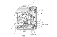
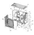
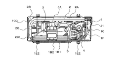
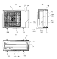
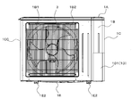
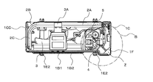
- FIG. 2A is a perspective view of the outdoor unit 100 according to the present embodiment.
- FIG. 2B is a perspective view of the outdoor unit 100 according to the present embodiment in an exploded state.
- FIG. 2C is a horizontal sectional view of the outdoor unit 100 according to the present embodiment.
- FIG. 2D is an enlarged view of region B shown in FIG. 2C.
- the outdoor unit 100 includes an outdoor heat exchanger 2 that functions as a condenser during a cooling operation and functions as an evaporator during a heating operation.
- the front panel 1B is defined as the front (front) of the outdoor unit, the side on which the first side panel 1CC is disposed toward the front is defined as the left side, and the second side toward the front.
- the side on which the panel 1C is disposed is defined as the right side.
- the casing of the outdoor unit 100 includes a top panel 1A that configures the upper surface of the outdoor unit 100, a front panel 1B that configures the front of the outdoor unit 100, and a first side panel 1CC that configures the left side of the outdoor unit 100.
- a second side panel 1C constituting the right side surface of the outdoor unit 100, a fan grill 1B2 provided on the front panel 1B and constituting a part of the front surface of the outdoor unit 100, and a bottom surface of the outdoor unit 100.
- a bottom panel 1E a bottom panel 1E.
- the 1st side panel 1CC, the front panel 1B, and the 2nd side panel 1C are the structures corresponding to a surrounding surface panel.
- the outdoor unit 100 includes a partition plate 5 that divides a space in the outdoor unit 100 into a left side and a right side, a compressor 4 that compresses and discharges refrigerant, an outdoor heat exchanger 2 that has an L-shaped horizontal cross section, an outdoor unit A blower 3 for supplying outside air to the heat exchanger 2 and a motor support 3A for holding the blower 3 are mounted.
- the outdoor unit 100 is also equipped with an electrical component box 6 provided with a control device for controlling the number of rotations of the four-way valve 8 and the compressor 4.
- the outdoor unit 100 is disposed at a corner C of the bottom panel 1E so as to be located inside the peripheral panel, and is fixed to the fixed panel 1F standing on the bottom panel 1E, the fixed panel 1F, and the refrigerant pipe P Are connected to each other, and a cover 1D attached to cover the valve 7 is provided.
- the top panel 1 ⁇ / b> A constitutes the upper surface of the outdoor unit 100.
- the top panel 1 ⁇ / b> A is provided at the upper end of the peripheral panel so as to cover the top of the outdoor heat exchanger 2.
- the top panel 1A is provided such that the front end and the left end are supported by being in contact with the front panel 1B and the first side panel 1CC, and the right end is in contact with and supported by the second side panel 1C.
- Top panel 1A is made of, for example, a metal plate.
- the front panel 1B constitutes a part of the front surface of the outdoor unit 100.
- the front panel 1B is provided with a first side panel 1CC at the left side end and a cover 1D at the right side end. Further, the front panel 1B is provided with a cover 1D at the right side end.
- the first side panel 1CC and the front panel 1B are connected and configured integrally.
- the front panel 1B has a lower end provided on the peripheral edge 1E1 of the bottom panel 1E, and a top panel 1A provided at the upper end.
- the right side edge part of the front surface component of the front panel 1B is provided along the side edge part on the front side of the second side panel 1C.
- the front panel 1B is formed with a circular opening 1B1 serving as an outside air inlet, for example.
- Fan grill 1B2 is provided so as to face the position where opening 1B1 is formed.
- Front panel 1B is made of, for example, resin.
- the first side panel 1CC is provided on the peripheral edge 1E1 of the bottom panel 1E.
- the first side panel 1CC is provided at a portion corresponding to one short side of the bottom panel 1E.
- the second side panel 1C is disposed at a position opposite to the first side panel 1CC.
- the front side surface portion of the first side panel 1CC is provided along the side end portion of the cover 1D.
- a plurality of openings are formed in the first side panel 1CC so that air is supplied to the outdoor heat exchanger 2.
- the second side panel 1C constitutes a part of the rear surface and the right side surface of the outdoor unit 100.
- the second side panel 1 ⁇ / b> C has a substantially L-shaped horizontal cross section, is vertically provided on the bottom panel 1 ⁇ / b> E, and is disposed on the side and rear side of the compressor 4.
- the second side panel 1C is provided such that the front end is along the side end of the cover 1D, the upper end is provided in contact with the top panel 1A, and the lower end is provided in contact with the bottom panel 1E. It has been.
- Second side panel 1C is made of, for example, ABS resin.
- the fan grille 1B2 constitutes a part of the front surface of the outdoor unit 100, and is used to prevent a user or the like from being injured by the blower 3.
- the fan grille 1B2 is a lattice-like member made up of vertical bars and horizontal bars, for example.
- the bottom panel 1E constitutes a part of the bottom surface of the outdoor unit 100.
- the bottom panel 1 ⁇ / b> E is a rectangular member that is disposed below the compressor 4 and the outdoor heat exchanger 2 and supports the compressor 4 and the outdoor heat exchanger 2.
- a peripheral edge 1E1 is formed on the periphery of the bottom panel 1E. That is, the peripheral edge 1E1 is a flange-shaped part formed on the peripheral edge of the bottom panel 1E.
- An outdoor heat exchanger 2, a compressor 4, a partition plate 5, and the like are provided above the bottom panel 1E.
- Bottom panel 1E is made of, for example, a metal plate.
- the leg part 1E2 utilized in order to mount the outdoor unit 100 is provided in the lower surface side of the bottom face panel 1E.
- Partition plate 5 The partition plate 5 is disposed so as to partition the side on which the compressor 4 and the valve 7 are disposed from the side on which the outdoor heat exchanger 2 and the blower 3 are disposed. That is, the partition plate 5 partitions the machine room R1 in which the compressor 4 is provided and the fan room R2 in which the outdoor heat exchanger 2, the blower 3, and the motor support 3A are provided. Partition plate 5 is disposed on bottom panel 1E, for example. And as for the partition plate 5, a front-end part is arrange
- the compressor 4 sucks the refrigerant, compresses the refrigerant, and discharges it in a high temperature / high pressure state.
- the compressor 4 is connected via a pipe to a four-way valve 8 that switches between a cooling operation and a heating operation by switching the refrigerant flow.
- a partition plate 5, a front panel 1B, a fixed panel 1F, and the like are arranged around the compressor 4, a partition plate 5, a front panel 1B, a fixed panel 1F, and the like are arranged.
- an electrical component box 6 used for various controls and the like is provided on the upper portion of the compressor 4.
- the compressor 4 does not need to be directly mounted on the bottom panel 1E, and may be mounted on the installation stand provided in the bottom panel 1E.
- Outdoor heat exchanger 2 The outdoor heat exchanger 2 performs heat exchange between the air taken into the outdoor unit 100 by the blower 3 and the refrigerant, condenses and liquefies the refrigerant during the cooling operation, and evaporates the refrigerant during the heating operation. .
- the outdoor heat exchanger 2 is provided on the bottom panel 1E, for example.
- the outdoor heat exchanger 2 does not need to be directly placed on the bottom panel 1E, and may be placed on an installation table provided on the bottom panel 1E.
- a motor support 3A On the upper part of the outdoor heat exchanger 2, a motor support 3A is provided so as to be hung.
- the outdoor heat exchanger 2 is configured by, for example, a fin-and-tube heat exchanger that can exchange heat between the refrigerant flowing through the heat transfer tubes and the air passing through the fins.
- the outdoor heat exchanger 2 includes a first heat exchange part 2A extending in parallel to the direction from the first side panel 1CC toward the second side panel 1C, a bent second heat exchange part 2B, And the third heat exchange part 2C provided to face the side panel 1CC.
- the first heat exchange unit 2A and the second heat exchange unit 2B are connected, and the second heat exchange unit 2B and the third heat exchange unit 2C are connected.
- a refrigerant circulation member 20 such as a header that distributes the refrigerant to various pipes and heat transfer pipes is disposed. That is, the refrigerant distribution member 20 is provided on the end side of the first heat exchange unit 2A.
- the third heat exchanging portion 2C is provided with a hairpin 2C1 in which the heat transfer tube is bent in a semicircular shape.
- the fixed panel 1F is configured to partition a space (machine room R1) on the side where the compressor 4 is disposed and a space on the side where the valve 7 is disposed.
- the fixed panel 1F is a flat plate-like member provided so as to extend in the vertical direction from the bottom panel 1E to the top panel 1A.
- the cover 1D and the second side panel 1C are also provided so as to extend in the vertical direction from the bottom panel 1E to the top panel 1A.
- One (front) side end of the fixed panel 1F is positioned to face the inner surface of the front panel 1B, and the other (rear) side end of the fixed panel 1F is the front end of the second side panel 1C. It is provided along the part.
- the fixed panel 1F is provided so as to form an acute angle with the front panel 1B.
- the valve 7 is attached to the fixed panel 1F.
- the valve 7 includes a narrow tube valve 7A and a thick tube valve 7B.
- a refrigerant pipe P is connected to the valve 7.
- the valve 7 is disposed in a closed space SP formed between the outer surface of the fixed panel 1F, the upper surface of the bottom panel 1E, and the inner surface of the cover 1D. For this reason, even if it ignites on the heat insulation cover wound around the refrigerant
- the cover 1D is disposed on the peripheral edge 1E1 of the bottom panel 1E and is detachably provided at a position facing the fixed panel 1F so as to cover the bulb 7.
- the cover 1D is attached at a position corresponding to the corner C of the bottom panel 1E.
- the cover 1D constitutes a part of the front surface and a part of the right side surface of the casing of the outdoor unit 100.
- the cover 1D has an L-shaped horizontal sectional view.
- the cover 1D is provided so as to extend in the vertical direction.
- the cover 1D includes a front surface portion 1D1 provided in parallel with the front panel 1B, a side surface portion 1D2 orthogonal to the front surface portion 1D1, and a drawer portion 1D3 used to draw out the refrigerant pipe P connected to the valve 7. It is a waste.
- the cover 1D is formed by integrally forming a front surface portion 1D1, a side surface portion 1D2, and a drawer portion 1D3.
- the cover 1D may be made of, for example, a resin or a metal plate.
- Front part 1D1 is a flat member formed to extend from bottom panel 1E to top panel 1A.
- the left side end portion of the front portion 1D1 is provided along the right end portion of the front panel 1B. Further, the right side end portion of the front surface portion 1D1 is connected to the side surface portion 1D2.
- Side part 1D2 is a flat plate-like member provided along the outer surface of second side panel 1C. Side part 1D2 is a flat plate-like member formed so as to extend from bottom panel 1E to top panel 1A.
- a drawer portion 1D3 is formed at the height position of the valve 7 at the rear side end portion of the side surface portion 1D2.
- the lead portion 1D3 is formed so as to protrude to the right side of the side surface portion 1D2.
- the side surface of the cover 1D has a stepped portion in which the lead portion 1D3 is formed. If the drawer 1D3 is not formed in the cover 1D, the refrigerant pipe P can be easily drawn, but rainwater or the like enters the casing of the outdoor unit 100. However, since the drawer 1D3 that protrudes from the side surface 1D2 is formed in the cover 1D, rainwater or the like can enter the housing of the outdoor unit 100 while avoiding interference with the refrigerant pipe P. Can be suppressed.
- the outdoor unit 100 according to the present embodiment is disposed at the corner C of the bottom panel 1E so as to be located inside the peripheral panel (the front panel 1B and the second side panel 1C), and is erected on the bottom panel 1E.
- the fixed panel 1 ⁇ / b> F and the valve 7 fixed to the fixed panel 1 ⁇ / b> F and connected to the refrigerant pipe P are provided.
- the valve 7 is positioned inside the peripheral edge portion 1E1 of the bottom panel 1E of the outdoor unit 100. That is, in the outdoor unit 100, it is possible to avoid the valve from jumping out from the outside of the casing of the outdoor unit as in the conventional outdoor unit. Therefore, the outdoor unit 100 according to the present embodiment can be reduced in size.
- the outdoor unit 100 since the fixed panel 1F is provided at the corner C of the bottom panel 1E, the outdoor unit 100 can be prevented from interfering with various pipes in the outdoor unit 100.
- the limited space within 100 can be used effectively.
- the valve 7 is provided on the fixed panel 1F, the heat insulating cover wound around the refrigerant pipe P connecting the inside and outside of the casing of the outdoor unit 100 is ignited. However, it is possible to prevent the flame from spreading into the machine room R1.
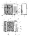
- FIG. 3A is a perspective view of Modification 1 of outdoor unit 100 according to the present embodiment.
- FIG. 3B is a perspective view of the outdoor unit 100 according to Modification 1 shown in FIG. 3A in an exploded state.
- FIG. 3C is a horizontal cross-sectional view of the outdoor unit 100 according to the second modification.
- FIG. 3D is an explanatory diagram in a state where the cover 1D of the outdoor unit 100 according to Modification 2 is removed.
- 3D (a) is a front view of the outdoor unit 100 according to Modification 1
- FIG. 3D (b) is a right side view of the outdoor unit 100 according to Modification 1
- FIG. 3D (c) are the perspective views of the outdoor unit 100 which concerns on the modification 1.
- FIG. In the first modification unlike the present embodiment, the height of the fixed panel 1F does not reach the top panel 1A.
- the front panel 1B has a front notch 1BH formed below the end of the second side panel 1C.
- the second side panel 1C has a side notch 1CH formed under the front side end portion that is the front panel 1B side.
- the fixed panel 1F is provided so as to extend from the bottom panel 1E side to the height positions of the upper ends of the front cutout 1BH and the side cutout 1CH.
- the cover 1D is provided in the front cutout 1BH and the side cutout 1CH.
- a roof panel 1FF is provided.
- the roof panel 1FF is connected to the upper end of the fixed panel 1F, the front cutout 1BH, and the side cutout 1CH, and is disposed on the upper side of the bulb 7.
- the roof panel 1FF can be composed of, for example, a triangular plate member.
- the roof panel 1FF is arranged so that the apex portion of the corner C of the bottom panel 1E comes below the apex.
- the apex of the roof panel 1FF is located at the corner of the right side end of the front panel 1B and the corner of the front side end of the second side panel 1C.
- this vertex has a larger angle than the other two vertices.
- the left side end portion of the front panel 1B and the front side end portion of the second side panel 1C are provided along.
- the front panel 1B and the second side panel 1C are separated from each other at the positions where the front notch 1BH and the side notch 1CH are formed.
- the outdoor unit 100 according to Modification 1 can increase the volume of the machine room R1 and is limited in the outdoor unit 100. There is an effect that it is easy to use space effectively.
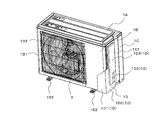
- FIG. 4A is a perspective view of Modification 2 of outdoor unit 100 according to the present embodiment.
- FIG. 4B is a perspective view of the outdoor unit 100 according to Modification 2 shown in FIG. 4A in an exploded state.
- FIG. 4C is a horizontal cross-sectional view of the outdoor unit 100 according to the second modification.
- FIG. 4D is an explanatory diagram in a state where the cover 1D of the outdoor unit 100 according to Modification 2 is removed.
- FIG. 4E is an explanatory diagram of the outdoor unit 100 according to the modified example 2, and is an explanatory diagram in a state where the cover 1D is attached.
- 4D (a) is a front view of the outdoor unit 100 according to Modification 2 and FIG.
- FIG. 4D (b) is a right side view of the outdoor unit 100 according to Modification 2.
- FIG. 4D (c) These are top view of the outdoor unit 100 which concerns on the modification 2.
- FIG. In the modification 2, the 1st protrusion part J is formed in the edge part of the outdoor heat exchanger 2, and it suppresses the enlargement of the outdoor unit 100, increasing the lateral width of the outdoor heat exchanger 2. It is possible.
- the bottom panel 1E includes a first protrusion J that is formed on the peripheral edge 1E1 where the second side panel 1C is provided and protrudes in the horizontal direction.
- This 1st protrusion part J is formed in the part corresponding to the edge part of 2 A of 1st heat exchange parts of the outdoor heat exchanger 2, and protrudes in a horizontal direction.
- the taper surface J1 which goes to the edge part of the 1st protrusion part J toward the part located in the lower side of the valve
- the cover 1D is formed with a terminal block protection portion 1D4 formed so as to cover the attachment portion Q such as a terminal block connected to the electrical component box 6.
- the terminal block protection part 1D4 is formed on the same plane as the drawer part 1D3, and is formed at a position protruding to the right side from the side part 1D2.
- the terminal block protection part 1D4 has a lower end connected to an upper end of the lead part 1D3. Further, the terminal block protection part 1D4 has a lower side end connected to the side part 1D2.
- the cover 1D is formed by integrally forming the front surface portion 1D1, the side surface portion 1D2, the drawer portion 1D3, and the terminal block protection portion 1D4. In the second modification, the cover 1D can protect not only the valve 7 but also the terminal block.
- outdoor unit 100 according to Modification 2 has the following effects. That is, in the outdoor unit 100 according to the modified example 2, the first protrusion J is formed at the end of the outdoor heat exchanger 2, and the lateral width of the outdoor heat exchanger 2 is increased, but the The increase in size can be suppressed.
- the second side panel 1C also has a tapered surface parallel to the tapered surface J1, so that the refrigerant pipe P can be disposed along the side surface. For this reason, it is possible to avoid the refrigerant pipe P from interfering and to prevent the refrigerant pipe P from being damaged.
- FIG. 5A is a front view of Modification 3 of outdoor unit 100 according to the present embodiment.
- FIG. 5B is a horizontal sectional view of the outdoor unit 100 according to Modification 3.
- FIG. 5C is an enlarged view of region B shown in FIG. 5B.
- FIG. 5D is an explanatory diagram in a state where the cover 1D of the outdoor unit 100 according to Modification 3 is removed.
- 5D (a) is a perspective view of the outdoor unit 100 according to the third modification
- FIG. 5D (b) is a top view of the outdoor unit 100 according to the third modification.
- the 2nd protrusion part Z is formed in the arrangement position of the valve
- the bottom panel 1E includes a second protrusion Z that is formed on the peripheral edge 1E1 on the side where the fixed panel 1F is provided and protrudes to the front side in the horizontal direction.
- the valve 7 is disposed on the upper side of the second protrusion Z.
- the front end of the second protrusion Z is provided so as not to protrude from the front end of the leg 1E2. That is, the front end of the second protrusion Z is disposed on the rear side in the front-rear direction of the casing of the outdoor unit 100 with respect to the front end of the leg 1E2.
- the outdoor unit 100 according to Modification 3 has the following effects in addition to the same effects as the outdoor unit 100 according to the present embodiment. That is, in the outdoor unit 100 according to the modified example 3, since the valve 7 is arranged above the second projecting portion Z, the volume of the machine room R1 can be increased correspondingly, and the outdoor unit 100 can be increased accordingly. The limited space inside can be used effectively. Further, the outdoor unit 100 according to the modified example 3 is provided so that the front end of the second projecting portion Z does not protrude from the front end of the leg portion 1E2, so that the transport efficiency of the outdoor unit 100 is not deteriorated. There is an effect that the machine room can be enlarged.
- the outdoor unit 100 according to the modified example 3 has the second protrusion Z formed on the bottom panel 1E, and the fixed panel 1F provided with the valve 7 is disposed at the position where the second protrusion Z is formed. Yes.
- the formation position of the second protrusion Z is a front space of the outdoor unit 100 and is a dead space that forms an air passage. For this reason, even if the outdoor unit 100 in which the 2nd protrusion part Z was formed is installed, it can avoid that it becomes difficult to use the space (a veranda etc.) in which the outdoor unit 100 was installed.
Landscapes
- Engineering & Computer Science (AREA)
- Chemical & Material Sciences (AREA)
- Combustion & Propulsion (AREA)
- Mechanical Engineering (AREA)
- General Engineering & Computer Science (AREA)
- Other Air-Conditioning Systems (AREA)
Priority Applications (6)
| Application Number | Priority Date | Filing Date | Title |
|---|---|---|---|
| JP2016565795A JP6227166B2 (ja) | 2014-12-26 | 2014-12-26 | 室外機 |
| PCT/JP2014/084489 WO2016103441A1 (ja) | 2014-12-26 | 2014-12-26 | 室外機 |
| US15/520,597 US10132512B2 (en) | 2014-12-26 | 2014-12-26 | Outdoor unit |
| CN201480083245.3A CN107076433B (zh) | 2014-12-26 | 2014-12-26 | 室外机 |
| EP14901009.2A EP3059509B1 (en) | 2014-12-26 | 2014-12-26 | Outdoor unit |
| CN201520788248.9U CN205174613U (zh) | 2014-12-26 | 2015-10-12 | 室外机 |
Applications Claiming Priority (1)
| Application Number | Priority Date | Filing Date | Title |
|---|---|---|---|
| PCT/JP2014/084489 WO2016103441A1 (ja) | 2014-12-26 | 2014-12-26 | 室外機 |
Publications (1)
| Publication Number | Publication Date |
|---|---|
| WO2016103441A1 true WO2016103441A1 (ja) | 2016-06-30 |
Family
ID=55738601
Family Applications (1)
| Application Number | Title | Priority Date | Filing Date |
|---|---|---|---|
| PCT/JP2014/084489 WO2016103441A1 (ja) | 2014-12-26 | 2014-12-26 | 室外機 |
Country Status (5)
| Country | Link |
|---|---|
| US (1) | US10132512B2 (zh) |
| EP (1) | EP3059509B1 (zh) |
| JP (1) | JP6227166B2 (zh) |
| CN (2) | CN107076433B (zh) |
| WO (1) | WO2016103441A1 (zh) |
Cited By (1)
| Publication number | Priority date | Publication date | Assignee | Title |
|---|---|---|---|---|
| CN111928349A (zh) * | 2020-08-24 | 2020-11-13 | 武汉宏海科技股份有限公司 | 一种新型空调外机前面板 |
Families Citing this family (7)
| Publication number | Priority date | Publication date | Assignee | Title |
|---|---|---|---|---|
| KR101900484B1 (ko) | 2015-01-23 | 2018-09-20 | 삼성전자주식회사 | 공기 조화기 |
| CN109028353B (zh) * | 2018-07-18 | 2020-05-22 | 广东美的制冷设备有限公司 | 空调室外机和空调器 |
| CN109163387A (zh) * | 2018-10-23 | 2019-01-08 | 珠海格力电器股份有限公司 | 一种用于空调室外机的气流反向结构及空调室外机 |
| JP2020128833A (ja) * | 2019-02-08 | 2020-08-27 | パナソニックIpマネジメント株式会社 | ヒートポンプシステム |
| USD957606S1 (en) | 2020-01-15 | 2022-07-12 | Lendell Martin, Sr. | Base for air system |
| US11976828B2 (en) * | 2020-03-30 | 2024-05-07 | Mitsubishi Electric Corporation | Outdoor unit of air-conditioning apparatus |
| CN112880127B (zh) * | 2021-01-28 | 2022-06-21 | 广东美的制冷设备有限公司 | 一种故障检测方法、装置、设备及存储介质 |
Citations (9)
| Publication number | Priority date | Publication date | Assignee | Title |
|---|---|---|---|---|
| US4153310A (en) * | 1978-06-26 | 1979-05-08 | Westinghouse Electric Corp. | Air conditioning outdoor section cabinet construction |
| JPS6425635U (zh) * | 1987-08-07 | 1989-02-13 | ||
| JPH05133571A (ja) | 1991-11-15 | 1993-05-28 | Matsushita Electric Ind Co Ltd | 空気調和機の室外ユニツト |
| JPH05296496A (ja) * | 1992-04-22 | 1993-11-09 | Mitsubishi Electric Corp | 空気調和機の室外ユニット |
| JPH08219495A (ja) * | 1995-02-08 | 1996-08-30 | Fujitsu General Ltd | 空気調和機の室外機 |
| JP2003254563A (ja) * | 2001-12-27 | 2003-09-10 | Sanyo Electric Co Ltd | 空気調和装置 |
| US20050204767A1 (en) * | 2002-05-24 | 2005-09-22 | Norrell Billy W | Base pan and cabinet for an air conditioner |
| JP2007120900A (ja) * | 2005-10-31 | 2007-05-17 | Daikin Ind Ltd | 閉鎖弁サポート部材及びそれを備えた空気調和装置の室外ユニット |
| US20130219942A1 (en) * | 2012-02-23 | 2013-08-29 | Rheem Manufacturing Company | Air Conditioner and Heat Pump Condensing Unit Chassis with Enhanced Serviceability Access |
Family Cites Families (4)
| Publication number | Priority date | Publication date | Assignee | Title |
|---|---|---|---|---|
| JP3523823B2 (ja) * | 2000-02-29 | 2004-04-26 | 東芝キヤリア株式会社 | 空気調和機の室外ユニット |
| JP2008020132A (ja) * | 2006-07-13 | 2008-01-31 | Daikin Ind Ltd | 空気調和機の室外機 |
| IT1400737B1 (it) * | 2009-05-20 | 2013-07-02 | Sanyo Electric Co | Unita' esterna per lo scambio di calore, particolarmente in scambiatori di calore e simili. |
| JP6099925B2 (ja) * | 2012-10-04 | 2017-03-22 | 三菱重工業株式会社 | 空気調和機の室外ユニット |
-
2014
- 2014-12-26 EP EP14901009.2A patent/EP3059509B1/en not_active Not-in-force
- 2014-12-26 JP JP2016565795A patent/JP6227166B2/ja active Active
- 2014-12-26 WO PCT/JP2014/084489 patent/WO2016103441A1/ja active Application Filing
- 2014-12-26 US US15/520,597 patent/US10132512B2/en not_active Expired - Fee Related
- 2014-12-26 CN CN201480083245.3A patent/CN107076433B/zh active Active
-
2015
- 2015-10-12 CN CN201520788248.9U patent/CN205174613U/zh active Active
Patent Citations (9)
| Publication number | Priority date | Publication date | Assignee | Title |
|---|---|---|---|---|
| US4153310A (en) * | 1978-06-26 | 1979-05-08 | Westinghouse Electric Corp. | Air conditioning outdoor section cabinet construction |
| JPS6425635U (zh) * | 1987-08-07 | 1989-02-13 | ||
| JPH05133571A (ja) | 1991-11-15 | 1993-05-28 | Matsushita Electric Ind Co Ltd | 空気調和機の室外ユニツト |
| JPH05296496A (ja) * | 1992-04-22 | 1993-11-09 | Mitsubishi Electric Corp | 空気調和機の室外ユニット |
| JPH08219495A (ja) * | 1995-02-08 | 1996-08-30 | Fujitsu General Ltd | 空気調和機の室外機 |
| JP2003254563A (ja) * | 2001-12-27 | 2003-09-10 | Sanyo Electric Co Ltd | 空気調和装置 |
| US20050204767A1 (en) * | 2002-05-24 | 2005-09-22 | Norrell Billy W | Base pan and cabinet for an air conditioner |
| JP2007120900A (ja) * | 2005-10-31 | 2007-05-17 | Daikin Ind Ltd | 閉鎖弁サポート部材及びそれを備えた空気調和装置の室外ユニット |
| US20130219942A1 (en) * | 2012-02-23 | 2013-08-29 | Rheem Manufacturing Company | Air Conditioner and Heat Pump Condensing Unit Chassis with Enhanced Serviceability Access |
Non-Patent Citations (1)
| Title |
|---|
| See also references of EP3059509A4 |
Cited By (1)
| Publication number | Priority date | Publication date | Assignee | Title |
|---|---|---|---|---|
| CN111928349A (zh) * | 2020-08-24 | 2020-11-13 | 武汉宏海科技股份有限公司 | 一种新型空调外机前面板 |
Also Published As
| Publication number | Publication date |
|---|---|
| EP3059509A4 (en) | 2016-12-28 |
| US10132512B2 (en) | 2018-11-20 |
| US20170314793A1 (en) | 2017-11-02 |
| CN107076433B (zh) | 2019-08-27 |
| CN205174613U (zh) | 2016-04-20 |
| EP3059509B1 (en) | 2019-05-08 |
| JP6227166B2 (ja) | 2017-11-08 |
| EP3059509A1 (en) | 2016-08-24 |
| JPWO2016103441A1 (ja) | 2017-04-27 |
| CN107076433A (zh) | 2017-08-18 |
Similar Documents
| Publication | Publication Date | Title |
|---|---|---|
| JP6227166B2 (ja) | 室外機 | |
| JP5218629B2 (ja) | ヒータ及びそれを備えた冷凍装置の室外ユニット | |
| JP6305619B2 (ja) | 室外機 | |
| EP2835587B1 (en) | Heat exchanger for air-conditioning device and air-conditioning device | |
| WO2013046724A1 (ja) | 室外機及び冷凍装置 | |
| JP6732110B2 (ja) | 室外機、空気調和機、及び、室外機の製造方法 | |
| JP6227167B2 (ja) | 室外機 | |
| JP2022146442A (ja) | 冷凍装置の室外ユニット | |
| KR20160077835A (ko) | 공기 조화기의 실외기 | |
| JP7086269B2 (ja) | 室内機 | |
| US11732971B2 (en) | Heat exchanger and air conditioner having the same | |
| JP7325600B2 (ja) | 室外機およびそれを備えた空気調和装置 | |
| WO2024071383A1 (ja) | ヒートポンプサイクル装置の室外機、及び、ヒートポンプサイクル装置 | |
| JP6835044B2 (ja) | 屋外空気調和装置 | |
| JP2024048129A (ja) | 空気調和機の室外機 | |
| KR200396503Y1 (ko) | 천정용 에어컨 | |
| JP5780189B2 (ja) | 空気調和機 | |
| KR100782989B1 (ko) | 천장형 공기조화기 |
Legal Events
| Date | Code | Title | Description |
|---|---|---|---|
| REEP | Request for entry into the european phase |
Ref document number: 2014901009 Country of ref document: EP |
|
| WWE | Wipo information: entry into national phase |
Ref document number: 2014901009 Country of ref document: EP |
|
| 121 | Ep: the epo has been informed by wipo that ep was designated in this application |
Ref document number: 14901009 Country of ref document: EP Kind code of ref document: A1 |
|
| ENP | Entry into the national phase |
Ref document number: 2016565795 Country of ref document: JP Kind code of ref document: A |
|
| WWE | Wipo information: entry into national phase |
Ref document number: 15520597 Country of ref document: US |
|
| NENP | Non-entry into the national phase |
Ref country code: DE |