WO2016098754A1 - 試料採取装置及び試料採取方法 - Google Patents
試料採取装置及び試料採取方法 Download PDFInfo
- Publication number
- WO2016098754A1 WO2016098754A1 PCT/JP2015/085002 JP2015085002W WO2016098754A1 WO 2016098754 A1 WO2016098754 A1 WO 2016098754A1 JP 2015085002 W JP2015085002 W JP 2015085002W WO 2016098754 A1 WO2016098754 A1 WO 2016098754A1
- Authority
- WO
- WIPO (PCT)
- Prior art keywords
- cylinder
- hydrogen
- valve
- hydrogen gas
- safety
- Prior art date
Links
- 238000000034 method Methods 0.000 title claims abstract description 24
- UFHFLCQGNIYNRP-UHFFFAOYSA-N Hydrogen Chemical compound [H][H] UFHFLCQGNIYNRP-UHFFFAOYSA-N 0.000 claims abstract description 143
- 239000001257 hydrogen Substances 0.000 claims abstract description 66
- 229910052739 hydrogen Inorganic materials 0.000 claims abstract description 66
- 238000005070 sampling Methods 0.000 claims abstract description 34
- 239000007789 gas Substances 0.000 claims abstract description 23
- 230000006837 decompression Effects 0.000 claims description 24
- 239000000446 fuel Substances 0.000 claims description 20
- 238000007599 discharging Methods 0.000 claims description 6
- 239000002737 fuel gas Substances 0.000 abstract 1
- 239000012535 impurity Substances 0.000 description 10
- 230000000694 effects Effects 0.000 description 4
- IJGRMHOSHXDMSA-UHFFFAOYSA-N Atomic nitrogen Chemical compound N#N IJGRMHOSHXDMSA-UHFFFAOYSA-N 0.000 description 2
- 238000005259 measurement Methods 0.000 description 2
- UGFAIRIUMAVXCW-UHFFFAOYSA-N Carbon monoxide Chemical compound [O+]#[C-] UGFAIRIUMAVXCW-UHFFFAOYSA-N 0.000 description 1
- RWSOTUBLDIXVET-UHFFFAOYSA-N Dihydrogen sulfide Chemical compound S RWSOTUBLDIXVET-UHFFFAOYSA-N 0.000 description 1
- 230000002411 adverse Effects 0.000 description 1
- QVGXLLKOCUKJST-UHFFFAOYSA-N atomic oxygen Chemical compound [O] QVGXLLKOCUKJST-UHFFFAOYSA-N 0.000 description 1
- 229910052799 carbon Inorganic materials 0.000 description 1
- 229910002091 carbon monoxide Inorganic materials 0.000 description 1
- 239000003054 catalyst Substances 0.000 description 1
- 238000010276 construction Methods 0.000 description 1
- 238000007796 conventional method Methods 0.000 description 1
- 238000001514 detection method Methods 0.000 description 1
- 238000011161 development Methods 0.000 description 1
- 230000007613 environmental effect Effects 0.000 description 1
- 229910000037 hydrogen sulfide Inorganic materials 0.000 description 1
- 238000009434 installation Methods 0.000 description 1
- 238000012423 maintenance Methods 0.000 description 1
- 239000000463 material Substances 0.000 description 1
- 229910052757 nitrogen Inorganic materials 0.000 description 1
- 239000001301 oxygen Substances 0.000 description 1
- 229910052760 oxygen Inorganic materials 0.000 description 1
- 238000010926 purge Methods 0.000 description 1
- 238000010792 warming Methods 0.000 description 1
- 239000002699 waste material Substances 0.000 description 1
Images


Classifications
-
- G—PHYSICS
- G01—MEASURING; TESTING
- G01N—INVESTIGATING OR ANALYSING MATERIALS BY DETERMINING THEIR CHEMICAL OR PHYSICAL PROPERTIES
- G01N1/00—Sampling; Preparing specimens for investigation
- G01N1/02—Devices for withdrawing samples
- G01N1/22—Devices for withdrawing samples in the gaseous state
- G01N1/2226—Sampling from a closed space, e.g. food package, head space
-
- F—MECHANICAL ENGINEERING; LIGHTING; HEATING; WEAPONS; BLASTING
- F17—STORING OR DISTRIBUTING GASES OR LIQUIDS
- F17C—VESSELS FOR CONTAINING OR STORING COMPRESSED, LIQUEFIED OR SOLIDIFIED GASES; FIXED-CAPACITY GAS-HOLDERS; FILLING VESSELS WITH, OR DISCHARGING FROM VESSELS, COMPRESSED, LIQUEFIED, OR SOLIDIFIED GASES
- F17C13/00—Details of vessels or of the filling or discharging of vessels
-
- G—PHYSICS
- G01—MEASURING; TESTING
- G01N—INVESTIGATING OR ANALYSING MATERIALS BY DETERMINING THEIR CHEMICAL OR PHYSICAL PROPERTIES
- G01N33/00—Investigating or analysing materials by specific methods not covered by groups G01N1/00 - G01N31/00
- G01N33/0004—Gaseous mixtures, e.g. polluted air
- G01N33/0009—General constructional details of gas analysers, e.g. portable test equipment
- G01N33/0011—Sample conditioning
- G01N33/0016—Sample conditioning by regulating a physical variable, e.g. pressure or temperature
-
- F—MECHANICAL ENGINEERING; LIGHTING; HEATING; WEAPONS; BLASTING
- F17—STORING OR DISTRIBUTING GASES OR LIQUIDS
- F17C—VESSELS FOR CONTAINING OR STORING COMPRESSED, LIQUEFIED OR SOLIDIFIED GASES; FIXED-CAPACITY GAS-HOLDERS; FILLING VESSELS WITH, OR DISCHARGING FROM VESSELS, COMPRESSED, LIQUEFIED, OR SOLIDIFIED GASES
- F17C2201/00—Vessel construction, in particular geometry, arrangement or size
- F17C2201/03—Orientation
- F17C2201/035—Orientation with substantially horizontal main axis
-
- F—MECHANICAL ENGINEERING; LIGHTING; HEATING; WEAPONS; BLASTING
- F17—STORING OR DISTRIBUTING GASES OR LIQUIDS
- F17C—VESSELS FOR CONTAINING OR STORING COMPRESSED, LIQUEFIED OR SOLIDIFIED GASES; FIXED-CAPACITY GAS-HOLDERS; FILLING VESSELS WITH, OR DISCHARGING FROM VESSELS, COMPRESSED, LIQUEFIED, OR SOLIDIFIED GASES
- F17C2201/00—Vessel construction, in particular geometry, arrangement or size
- F17C2201/05—Size
- F17C2201/056—Small (<1 m3)
-
- F—MECHANICAL ENGINEERING; LIGHTING; HEATING; WEAPONS; BLASTING
- F17—STORING OR DISTRIBUTING GASES OR LIQUIDS
- F17C—VESSELS FOR CONTAINING OR STORING COMPRESSED, LIQUEFIED OR SOLIDIFIED GASES; FIXED-CAPACITY GAS-HOLDERS; FILLING VESSELS WITH, OR DISCHARGING FROM VESSELS, COMPRESSED, LIQUEFIED, OR SOLIDIFIED GASES
- F17C2205/00—Vessel construction, in particular mounting arrangements, attachments or identifications means
- F17C2205/01—Mounting arrangements
- F17C2205/0103—Exterior arrangements
- F17C2205/0107—Frames
-
- F—MECHANICAL ENGINEERING; LIGHTING; HEATING; WEAPONS; BLASTING
- F17—STORING OR DISTRIBUTING GASES OR LIQUIDS
- F17C—VESSELS FOR CONTAINING OR STORING COMPRESSED, LIQUEFIED OR SOLIDIFIED GASES; FIXED-CAPACITY GAS-HOLDERS; FILLING VESSELS WITH, OR DISCHARGING FROM VESSELS, COMPRESSED, LIQUEFIED, OR SOLIDIFIED GASES
- F17C2205/00—Vessel construction, in particular mounting arrangements, attachments or identifications means
- F17C2205/01—Mounting arrangements
- F17C2205/0103—Exterior arrangements
- F17C2205/0111—Boxes
-
- F—MECHANICAL ENGINEERING; LIGHTING; HEATING; WEAPONS; BLASTING
- F17—STORING OR DISTRIBUTING GASES OR LIQUIDS
- F17C—VESSELS FOR CONTAINING OR STORING COMPRESSED, LIQUEFIED OR SOLIDIFIED GASES; FIXED-CAPACITY GAS-HOLDERS; FILLING VESSELS WITH, OR DISCHARGING FROM VESSELS, COMPRESSED, LIQUEFIED, OR SOLIDIFIED GASES
- F17C2205/00—Vessel construction, in particular mounting arrangements, attachments or identifications means
- F17C2205/01—Mounting arrangements
- F17C2205/0153—Details of mounting arrangements
- F17C2205/0157—Details of mounting arrangements for transport
- F17C2205/0161—Details of mounting arrangements for transport with wheels
-
- F—MECHANICAL ENGINEERING; LIGHTING; HEATING; WEAPONS; BLASTING
- F17—STORING OR DISTRIBUTING GASES OR LIQUIDS
- F17C—VESSELS FOR CONTAINING OR STORING COMPRESSED, LIQUEFIED OR SOLIDIFIED GASES; FIXED-CAPACITY GAS-HOLDERS; FILLING VESSELS WITH, OR DISCHARGING FROM VESSELS, COMPRESSED, LIQUEFIED, OR SOLIDIFIED GASES
- F17C2205/00—Vessel construction, in particular mounting arrangements, attachments or identifications means
- F17C2205/03—Fluid connections, filters, valves, closure means or other attachments
- F17C2205/0302—Fittings, valves, filters, or components in connection with the gas storage device
- F17C2205/0311—Closure means
- F17C2205/0314—Closure means breakable, e.g. with burst discs
-
- F—MECHANICAL ENGINEERING; LIGHTING; HEATING; WEAPONS; BLASTING
- F17—STORING OR DISTRIBUTING GASES OR LIQUIDS
- F17C—VESSELS FOR CONTAINING OR STORING COMPRESSED, LIQUEFIED OR SOLIDIFIED GASES; FIXED-CAPACITY GAS-HOLDERS; FILLING VESSELS WITH, OR DISCHARGING FROM VESSELS, COMPRESSED, LIQUEFIED, OR SOLIDIFIED GASES
- F17C2205/00—Vessel construction, in particular mounting arrangements, attachments or identifications means
- F17C2205/03—Fluid connections, filters, valves, closure means or other attachments
- F17C2205/0302—Fittings, valves, filters, or components in connection with the gas storage device
- F17C2205/0323—Valves
- F17C2205/0332—Safety valves or pressure relief valves
-
- F—MECHANICAL ENGINEERING; LIGHTING; HEATING; WEAPONS; BLASTING
- F17—STORING OR DISTRIBUTING GASES OR LIQUIDS
- F17C—VESSELS FOR CONTAINING OR STORING COMPRESSED, LIQUEFIED OR SOLIDIFIED GASES; FIXED-CAPACITY GAS-HOLDERS; FILLING VESSELS WITH, OR DISCHARGING FROM VESSELS, COMPRESSED, LIQUEFIED, OR SOLIDIFIED GASES
- F17C2205/00—Vessel construction, in particular mounting arrangements, attachments or identifications means
- F17C2205/03—Fluid connections, filters, valves, closure means or other attachments
- F17C2205/0302—Fittings, valves, filters, or components in connection with the gas storage device
- F17C2205/0323—Valves
- F17C2205/0335—Check-valves or non-return valves
-
- F—MECHANICAL ENGINEERING; LIGHTING; HEATING; WEAPONS; BLASTING
- F17—STORING OR DISTRIBUTING GASES OR LIQUIDS
- F17C—VESSELS FOR CONTAINING OR STORING COMPRESSED, LIQUEFIED OR SOLIDIFIED GASES; FIXED-CAPACITY GAS-HOLDERS; FILLING VESSELS WITH, OR DISCHARGING FROM VESSELS, COMPRESSED, LIQUEFIED, OR SOLIDIFIED GASES
- F17C2205/00—Vessel construction, in particular mounting arrangements, attachments or identifications means
- F17C2205/03—Fluid connections, filters, valves, closure means or other attachments
- F17C2205/0302—Fittings, valves, filters, or components in connection with the gas storage device
- F17C2205/0338—Pressure regulators
-
- F—MECHANICAL ENGINEERING; LIGHTING; HEATING; WEAPONS; BLASTING
- F17—STORING OR DISTRIBUTING GASES OR LIQUIDS
- F17C—VESSELS FOR CONTAINING OR STORING COMPRESSED, LIQUEFIED OR SOLIDIFIED GASES; FIXED-CAPACITY GAS-HOLDERS; FILLING VESSELS WITH, OR DISCHARGING FROM VESSELS, COMPRESSED, LIQUEFIED, OR SOLIDIFIED GASES
- F17C2205/00—Vessel construction, in particular mounting arrangements, attachments or identifications means
- F17C2205/03—Fluid connections, filters, valves, closure means or other attachments
- F17C2205/0302—Fittings, valves, filters, or components in connection with the gas storage device
- F17C2205/0352—Pipes
- F17C2205/0364—Pipes flexible or articulated, e.g. a hose
-
- F—MECHANICAL ENGINEERING; LIGHTING; HEATING; WEAPONS; BLASTING
- F17—STORING OR DISTRIBUTING GASES OR LIQUIDS
- F17C—VESSELS FOR CONTAINING OR STORING COMPRESSED, LIQUEFIED OR SOLIDIFIED GASES; FIXED-CAPACITY GAS-HOLDERS; FILLING VESSELS WITH, OR DISCHARGING FROM VESSELS, COMPRESSED, LIQUEFIED, OR SOLIDIFIED GASES
- F17C2221/00—Handled fluid, in particular type of fluid
- F17C2221/01—Pure fluids
- F17C2221/012—Hydrogen
-
- F—MECHANICAL ENGINEERING; LIGHTING; HEATING; WEAPONS; BLASTING
- F17—STORING OR DISTRIBUTING GASES OR LIQUIDS
- F17C—VESSELS FOR CONTAINING OR STORING COMPRESSED, LIQUEFIED OR SOLIDIFIED GASES; FIXED-CAPACITY GAS-HOLDERS; FILLING VESSELS WITH, OR DISCHARGING FROM VESSELS, COMPRESSED, LIQUEFIED, OR SOLIDIFIED GASES
- F17C2223/00—Handled fluid before transfer, i.e. state of fluid when stored in the vessel or before transfer from the vessel
- F17C2223/01—Handled fluid before transfer, i.e. state of fluid when stored in the vessel or before transfer from the vessel characterised by the phase
- F17C2223/0107—Single phase
- F17C2223/0123—Single phase gaseous, e.g. CNG, GNC
-
- F—MECHANICAL ENGINEERING; LIGHTING; HEATING; WEAPONS; BLASTING
- F17—STORING OR DISTRIBUTING GASES OR LIQUIDS
- F17C—VESSELS FOR CONTAINING OR STORING COMPRESSED, LIQUEFIED OR SOLIDIFIED GASES; FIXED-CAPACITY GAS-HOLDERS; FILLING VESSELS WITH, OR DISCHARGING FROM VESSELS, COMPRESSED, LIQUEFIED, OR SOLIDIFIED GASES
- F17C2223/00—Handled fluid before transfer, i.e. state of fluid when stored in the vessel or before transfer from the vessel
- F17C2223/03—Handled fluid before transfer, i.e. state of fluid when stored in the vessel or before transfer from the vessel characterised by the pressure level
- F17C2223/036—Very high pressure (>80 bar)
-
- F—MECHANICAL ENGINEERING; LIGHTING; HEATING; WEAPONS; BLASTING
- F17—STORING OR DISTRIBUTING GASES OR LIQUIDS
- F17C—VESSELS FOR CONTAINING OR STORING COMPRESSED, LIQUEFIED OR SOLIDIFIED GASES; FIXED-CAPACITY GAS-HOLDERS; FILLING VESSELS WITH, OR DISCHARGING FROM VESSELS, COMPRESSED, LIQUEFIED, OR SOLIDIFIED GASES
- F17C2225/00—Handled fluid after transfer, i.e. state of fluid after transfer from the vessel
- F17C2225/01—Handled fluid after transfer, i.e. state of fluid after transfer from the vessel characterised by the phase
- F17C2225/0107—Single phase
- F17C2225/0123—Single phase gaseous, e.g. CNG, GNC
-
- F—MECHANICAL ENGINEERING; LIGHTING; HEATING; WEAPONS; BLASTING
- F17—STORING OR DISTRIBUTING GASES OR LIQUIDS
- F17C—VESSELS FOR CONTAINING OR STORING COMPRESSED, LIQUEFIED OR SOLIDIFIED GASES; FIXED-CAPACITY GAS-HOLDERS; FILLING VESSELS WITH, OR DISCHARGING FROM VESSELS, COMPRESSED, LIQUEFIED, OR SOLIDIFIED GASES
- F17C2225/00—Handled fluid after transfer, i.e. state of fluid after transfer from the vessel
- F17C2225/03—Handled fluid after transfer, i.e. state of fluid after transfer from the vessel characterised by the pressure level
- F17C2225/035—High pressure, i.e. between 10 and 80 bars
-
- F—MECHANICAL ENGINEERING; LIGHTING; HEATING; WEAPONS; BLASTING
- F17—STORING OR DISTRIBUTING GASES OR LIQUIDS
- F17C—VESSELS FOR CONTAINING OR STORING COMPRESSED, LIQUEFIED OR SOLIDIFIED GASES; FIXED-CAPACITY GAS-HOLDERS; FILLING VESSELS WITH, OR DISCHARGING FROM VESSELS, COMPRESSED, LIQUEFIED, OR SOLIDIFIED GASES
- F17C2250/00—Accessories; Control means; Indicating, measuring or monitoring of parameters
- F17C2250/06—Controlling or regulating of parameters as output values
- F17C2250/0605—Parameters
- F17C2250/0636—Flow or movement of content
-
- F—MECHANICAL ENGINEERING; LIGHTING; HEATING; WEAPONS; BLASTING
- F17—STORING OR DISTRIBUTING GASES OR LIQUIDS
- F17C—VESSELS FOR CONTAINING OR STORING COMPRESSED, LIQUEFIED OR SOLIDIFIED GASES; FIXED-CAPACITY GAS-HOLDERS; FILLING VESSELS WITH, OR DISCHARGING FROM VESSELS, COMPRESSED, LIQUEFIED, OR SOLIDIFIED GASES
- F17C2265/00—Effects achieved by gas storage or gas handling
- F17C2265/06—Fluid distribution
- F17C2265/065—Fluid distribution for refueling vehicle fuel tanks
-
- F—MECHANICAL ENGINEERING; LIGHTING; HEATING; WEAPONS; BLASTING
- F17—STORING OR DISTRIBUTING GASES OR LIQUIDS
- F17C—VESSELS FOR CONTAINING OR STORING COMPRESSED, LIQUEFIED OR SOLIDIFIED GASES; FIXED-CAPACITY GAS-HOLDERS; FILLING VESSELS WITH, OR DISCHARGING FROM VESSELS, COMPRESSED, LIQUEFIED, OR SOLIDIFIED GASES
- F17C2270/00—Applications
- F17C2270/01—Applications for fluid transport or storage
- F17C2270/0134—Applications for fluid transport or storage placed above the ground
- F17C2270/0139—Fuel stations
-
- G—PHYSICS
- G01—MEASURING; TESTING
- G01N—INVESTIGATING OR ANALYSING MATERIALS BY DETERMINING THEIR CHEMICAL OR PHYSICAL PROPERTIES
- G01N1/00—Sampling; Preparing specimens for investigation
- G01N1/02—Devices for withdrawing samples
- G01N1/22—Devices for withdrawing samples in the gaseous state
- G01N1/2226—Sampling from a closed space, e.g. food package, head space
- G01N2001/2238—Sampling from a closed space, e.g. food package, head space the gas being compressed or pressurized
-
- Y—GENERAL TAGGING OF NEW TECHNOLOGICAL DEVELOPMENTS; GENERAL TAGGING OF CROSS-SECTIONAL TECHNOLOGIES SPANNING OVER SEVERAL SECTIONS OF THE IPC; TECHNICAL SUBJECTS COVERED BY FORMER USPC CROSS-REFERENCE ART COLLECTIONS [XRACs] AND DIGESTS
- Y02—TECHNOLOGIES OR APPLICATIONS FOR MITIGATION OR ADAPTATION AGAINST CLIMATE CHANGE
- Y02E—REDUCTION OF GREENHOUSE GAS [GHG] EMISSIONS, RELATED TO ENERGY GENERATION, TRANSMISSION OR DISTRIBUTION
- Y02E60/00—Enabling technologies; Technologies with a potential or indirect contribution to GHG emissions mitigation
- Y02E60/30—Hydrogen technology
- Y02E60/32—Hydrogen storage
Definitions
- the present invention relates to a sampling device and a sampling method for analyzing impurities in a fuel hydrogen gas supplied as a fuel for a fuel cell vehicle or the like at a hydrogen station or the like, and more particularly to a fuel hydrogen gas for a fuel cell.
- This is a technique that is composed of a decompression safety unit and a cylinder unit that collects sample hydrogen gas from a storage container into a cylinder, and has safety and portability.
- the hydrogen gas For fuel hydrogen gas supplied to hydrogen vehicles at hydrogen stations, etc., if the hydrogen gas contains impurities such as carbon monoxide and hydrogen sulfide, the performance of the fuel cell catalyst will deteriorate.
- the maximum allowable concentration of various impurities is specified. Therefore, it is necessary to identify and quantify the multiple impurities in the fuel hydrogen gas supplied to the hydrogen vehicle at a hydrogen station, etc., and confirm that the various impurities in the hydrogen gas are below the maximum allowable concentration. In addition, more accurate impurity analysis is required on a regular basis.
- sample collection devices and sample collection methods include gas sampling containers equipped with safety valve devices (see, for example, Patent Document 1), high-purity gas samplers (see, for example, Patent Document 2), and rapid gas samplers. (For example, refer to Patent Document 3).
- Patent Document 1 Patent Document 2, Patent Document 3
- the present invention is intended to solve such problems of the prior art, and maintains safety with a rupture disc and a safety valve, and prevents unnecessary exhaust of hydrogen gas.
- the purpose is to collect sample hydrogen gas in a plurality of cylinders from a plurality of hydrogen stations or the like by transporting one sample collection device.
- the sample collection device of the present invention is a sample collection device comprising a decompression safety unit for collecting a hydrogen gas for a sample from a storage container for fuel hydrogen gas supplied to a hydrogen vehicle and a cylinder unit.
- the decompression safety unit forms an equipment storage chamber for storing equipment, and a cylinder connection chamber capable of connecting a flexible hose for collection to the cylinder,
- the equipment storage chamber includes a supply line for introducing high-pressure hydrogen gas from the storage container, a safety line for discharging hydrogen gas in the supply line when a set pressure is exceeded, and a supply line.
- An exhaust pipe for exhausting the gas in the pipe leading to the cylinder A hydrogen inlet from the storage container is provided at one end of the supply pipeline, a hydrogen outlet to the cylinder is provided at the other end of the supply pipeline, and the hydrogen outlet is connected to the equipment storage chamber and the cylinder connection chamber.
- a pressure reducing valve for reducing the pressure of the high-pressure hydrogen gas introduced from the hydrogen inlet to the supply line; and a flow rate adjusting valve for adjusting the flow rate of the hydrogen gas reduced by the pressure reducing valve; From the branch part in the supply line in the middle of the pressure reducing valve and the flow rate control valve, branch the safety line and the exhaust line provided with an exhaust on-off valve, In order to the safety line in order from the branch part of the supply line, a rupture disk that releases the block of the safety line above the first set pressure, and a second set pressure lower than the first set pressure With a safety valve that opens and closes at a third set pressure lower than the second set pressure,
- the cylinder connection chamber has an opening surface portion opened to the outside,
- the cylinder unit is detachably accommodated in a casing capable of opening and closing the cylinder, except for the tip of the cylinder, the base and the exposed portion exposing the cylinder opening / closing valve.
- the exposed portion of the cylinder is formed so as to be insertable into the cylinder connection chamber from the opening surface portion of the cylinder connection chamber, and the base of the cylinder and the hydrogen outlet are connected by the flexible hose, and the sample hydrogen gas Is collected in the cylinder.
- the sample collection method of the present invention is a sample collection device comprising a decompression safety unit for collecting sample hydrogen gas from a storage container for fuel hydrogen gas supplied to a hydrogen vehicle into a cylinder and a cylinder unit.
- the decompression safety unit forms an equipment storage chamber for storing equipment, and a cylinder connection chamber capable of connecting a flexible hose for collection to the cylinder,
- the equipment storage chamber includes a supply line for introducing high-pressure hydrogen gas from the storage container, a safety line for discharging hydrogen gas in the supply line when a set pressure is exceeded, and a supply line.
- An exhaust pipe for exhausting the gas in the pipe leading to the cylinder A hydrogen inlet from the storage container is provided at one end of the supply pipeline, a hydrogen outlet to the cylinder is provided at the other end of the supply pipeline, and the hydrogen outlet is connected to the equipment storage chamber and the cylinder connection chamber.
- a pressure reducing valve for reducing the pressure of the high-pressure hydrogen gas introduced from the hydrogen inlet to the supply line; and a flow rate adjusting valve for adjusting the flow rate of the hydrogen gas reduced by the pressure reducing valve; From the branch part in the supply line in the middle of the pressure reducing valve and the flow rate control valve, branch the safety line and the exhaust line provided with an exhaust on-off valve, In order to the safety line in order from the branch part of the supply line, a rupture disk that releases the block of the safety line above the first set pressure, and a second set pressure lower than the first set pressure With a safety valve that opens and closes at a third set pressure lower than the second set pressure,
- the cylinder connection chamber has an opening surface portion opened to the outside,
- the cylinder unit is detachably accommodated in a casing capable of opening and closing the cylinder, except for the tip of the cylinder, the base and the exposed portion exposing the cylinder opening / closing valve.
- the exposed portion of the cylinder is inserted into the cylinder connection chamber from the opening surface portion of the cylinder connection chamber, the base of the cylinder and the hydrogen outlet are connected by the flexible hose, and the hydrogen inlet is connected to the storage container Connected to the filling port of The flow control valve is opened to fill the supply pipe, the flexible hose, and the exhaust pipe with hydrogen gas, then the flow control valve is closed to stop filling, and the exhaust on / off valve is opened. And exhausting the residual hydrogen gas in the cylinder by opening the cylinder opening / closing valve, The exhaust on-off valve is closed, the flow rate control valve is opened, and filling of the cylinder from the storage container is started, and the sample hydrogen gas is collected in the cylinder.
- a sampling device or a sampling method of the present invention in addition to the configuration of the sampling device of claim 1 or the configuration of the sampling method of claim 2,
- the bottom frame is provided with four moving wheels at the bottom and is portable, and the cylinder unit is provided with four moving wheels at the bottom and is portable.
- the sampling device or sampling method of the present invention according to claim 4 is added to the configuration of the sampling device according to claim 1 or 3, or in addition to the configuration of the sampling method according to claim 2 or 3,
- the cylinder unit casing has a horizontally long rectangular parallelepiped shape, the upper surface is divided at the center in the longitudinal direction, and the longitudinal section perpendicular to the longitudinal direction is formed into a pair of casings each having an L-shaped side surface and a divided upper surface.
- a plurality of hinges are provided at the lower end of each side surface of the casing, and an opening / closing handle is provided on each of the pair of divided upper surfaces to form a pair of openable / closable casings.
- the sample collection device or sample collection method of the present invention according to claim 5 is added to the configuration of the sample collection device according to claim 3 or the configuration of the sample collection method according to claim 3,
- a U-shaped frame provided with a pair of frame members parallel to the longitudinal direction of the cylinder and a first handle for connecting one end of the pair of frame members; and provided at an end of the frame
- a pair of wheels a connecting member for connecting the vicinity of the end of the frame, and one end rotatably mounted with the center of the connecting member as a fulcrum, and the other end as a fulcrum at the center in the longitudinal direction of the bottom frame of the cylinder unit
- a pivoting arm that is pivotably attached as a pair of wheels provided on the frame, and a pivoting frame having a variable position.
- a first locking portion and a second locking portion that lock the first handle are formed on the bottom frame
- the pair of position-variable wheels are positioned in the vicinity of the other pair of wheels on the bottom side of the cylinder by rotating the rotating frame and locking the first handle to the first locking portion.
- the rotating arm and the U-shaped frame body form a predetermined angle and one pair of The wheel and the other pair of wheels are located at a predetermined distance apart on the same plane, and the cylinder unit is in an inclined state.
- the sampling device of the present invention according to claim 1 or the sampling method according to claim 2 is provided in a supply line in the middle of a flow control valve and a pressure reducing valve provided in a supply line provided in the pressure reducing safety unit.
- the safety pipe and the exhaust pipe with an exhaust on-off valve are branched from the branch, and the safety valve is sealed in order from the branch point of the supply pipe to the safety pipe, and the safety pipe is sealed above the first set pressure.
- a safety valve that opens at a second set pressure lower than the first set pressure and closes at a third set pressure lower than the second set pressure.
- the sampling device is formed of a decompression safety unit and a cylinder unit, and the cylinder unit is placed in a casing capable of opening and closing the cylinder, except for the tip of the cylinder, the base and the exposed part exposing the cylinder opening / closing valve.
- the exposed portion of the cylinder is formed so as to be insertable into the cylinder connection chamber from the opening surface portion of the cylinder connection chamber, and the base of the cylinder and the hydrogen outlet are connected by the flexible hose, and the sample hydrogen gas Since the sample hydrogen gas cylinder can be exchanged, the fuel hydrogen supplied to the hydrogen vehicle at a plurality of hydrogen stations can be transferred by transporting one sample collection device. Sample hydrogen gas can be collected from a gas storage container into a plurality of cylinders.
- the decompression safety unit according to claim 3 The bottom frame is provided with four moving wheels and is portable, and the cylinder unit is provided with four moving wheels at the bottom and is portable. When collecting the gas, the decompression safety unit and the cylinder unit can be moved and installed and removed easily.
- the sampling device or sampling method of the present invention according to claim 4 includes a cylinder in addition to the effect of the sampling device of the present invention according to claim 1 or 2, or the sampling method of the present invention according to claim 2 or 3.
- the casing of the unit is in the shape of a horizontally long rectangular parallelepiped, the upper surface is divided at the center in the longitudinal direction, and the longitudinal section perpendicular to the longitudinal direction is formed into a pair of casings consisting of L-shaped side surfaces and the divided upper surface.
- a plurality of hinges are provided at the lower end of each side surface, and an opening / closing handle is provided on each pair of divided upper surfaces to form a pair of openable / closable casings, so that the cylinder can be easily attached to and detached from the cylinder unit. .
- the sample collection device or sample collection method of the present invention according to claim 5 includes a pair of cylinders parallel to the longitudinal direction of the cylinder.
- a U-shaped frame provided with a first handle for connecting one end of the frame member and the pair of frame members, a pair of wheels provided at the end of the frame, and the vicinity of the end of the frame
- a connecting member to be connected and a rotating arm having one end rotatably attached to the center of the connecting member as a fulcrum and the other end rotatably attached to the longitudinal center of the bottom frame of the cylinder unit as a fulcrum.
- a rotating frame with variable position of a pair of wheels provided on the frame When the rotating frame is rotated, a first locking portion and a second locking portion for locking the first handle are formed on the bottom frame, A pair of position-variable wheels are positioned in the vicinity of the other pair of wheels on the bottom side of the cylinder by rotating the rotating frame and locking the first handle to the first locking portion.
- the rotating arm and the U-shaped frame body By rotating the rotating frame and locking the first handle to the second locking portion, the rotating arm and the U-shaped frame body form a predetermined angle and one pair of Since the cylinder unit and the other pair of wheels are located at a predetermined distance on the same plane and the cylinder unit is inclined, the form (posture) of the cylinder unit can be changed to facilitate handling. It is.
- FIG. 3 is a plan view of FIG. 2. It is a front view which shows the apparatus of the pressure reduction safety unit which concerns on embodiment of this invention.
- FIG. 5 is a side view of FIG. 4.
- FIG. 6 is a plan view of FIG. 5. It is a front view shown in the state where the cylinder unit concerning an embodiment of the invention was turned upside down.
- FIG. 8 is a right side view of FIG. 7. It is the top view of FIG. 8 which showed the open / close state of the casing. It is a front view which shows the state which made the cylinder unit which concerns on embodiment of this invention slant.
- FIGS. 2 to 3 are drawings of a sampling device according to the embodiment of the present invention
- FIGS. 4 to 6 are drawings of a decompression safety unit constituting the sampling device according to the embodiment of the present invention
- FIGS. 10 is a drawing of a cylinder unit constituting the sample collection device according to the embodiment of the present invention.
- the sampling device 1 supplies a hydrogen gas for a sample 7 to a cylinder 7 through a nozzle (not shown) for filling a hydrogen vehicle on-board container from a fuel hydrogen gas storage container supplied to a hydrogen vehicle such as a hydrogen station. It consists of a decompression safety unit 2 and a cylinder unit 3 that perform sampling.
- the cylinder 7 needs to identify and quantify a plurality of impurities in the fuel hydrogen gas supplied to the hydrogen vehicle at a hydrogen station or the like to confirm that the various impurities in the hydrogen gas are below the maximum allowable concentration.
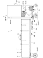
- the decompression safety unit 2 has two upper and lower frames 21a and 22a, and the upper frame 21a has a device storage chamber 21 for storing various devices, and the lower frame 22a can be used for collecting sample hydrogen gas.
- a cylinder connection chamber 22 for connecting the flexible hose 8 to the cylinder 7 is formed.
- the equipment storage chamber 21 has a supply line 4 for introducing high-pressure hydrogen gas of 70 MPa from a storage container for fuel hydrogen gas supplied to a hydrogen vehicle at a hydrogen station or the like, and when a set pressure exceeds 14.5 MPa, for example.
- a safety line 5 for discharging the hydrogen gas in the supply line 4
- an exhaust line 6 for discharging the gas in the pipe from the supply line 4 to the cylinder 7.
- a hydrogen inlet 41 from the storage container is provided at one end of the supply pipeline 4
- a hydrogen outlet 42 to the cylinder 7 is provided at the other end of the supply pipeline 4
- the hydrogen outlet 42 is connected to the equipment storage chamber 21 and the cylinder connection chamber. It is arranged in the vicinity of the boundary with 22.
- a pressure reducing valve 43 for reducing the pressure of the 70 MPa high-pressure hydrogen gas introduced from the hydrogen inlet 41 to 14 MPa and a flow rate adjusting valve 44 for adjusting the flow rate of the hydrogen gas reduced by the pressure reducing valve 43 are supplied to the supply line 4.
- a safety pipe 5 and an exhaust pipe 6 having an exhaust opening / closing valve 61 are branched from a branching portion 45 in the supply pipe 4 between the flow rate adjusting valve 44 and the pressure reducing valve 43.
- a safety valve 53 is provided which opens at the set pressure and closes at a pressure lower than the second set pressure.
- the cylinder 7 has specifications of a model 47L (7 type), an internal volume 47L, a diameter 232 mm, a length 1320 mm, a filling amount 7 m 3 (14.7 MPa), and the first set pressure is 14.5 MPa. It matches the specifications of the cylinder 7 with a maximum working pressure of 14.7 MPa.
- the rupturable plate 51 When the second set pressure is 14.0 MPa and the third set pressure is 13.5 MPa, and the inside of the safety line 5 becomes the first set pressure, the rupturable plate 51 immediately bursts and the safety line 5 is blocked. The hydrogen gas is discharged through the safety valve 53 and the safety is maintained. The safety valve 53 is automatically closed when the inside of the safety line 5 is lowered to the third set pressure due to exhaust, and prevents unnecessary exhaust of hydrogen gas.
- the rupture plate 51 is provided and the pressure gauge 54 is provided, unlike the case where only the safety valve 53 is installed, there is no inflow of atmospheric components from the outside, and when the rupture plate 51 has a fine crack.
- the pressure gauge 54 can be used for detection, adverse effects on the measurement of the concentration of nitrogen and oxygen, which are measurement items of the collected sample, can be prevented more effectively.
- the bottom surface of the device storage chamber 21 and the top surface of the cylinder connection chamber 22 are formed by placing the upper frame 21a so as to overlap the lower frame 22a.
- the cylinder connection chamber 22 has an open opening 22b on the left side surface.
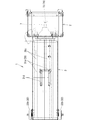
- the cylinder unit 3 includes a cylinder 7 in a cylinder 31 provided with a casing 31a capable of opening and closing the cylinder 7 except for a tip portion 71 of the cylinder 7, a base 72, and an exposed portion 74 exposing the on-off valve 73.
- the unit is leveled and detachable.
- the exposed portion 74 of the cylinder 7 can be inserted into the cylinder connection chamber 22 from the opening surface 22b of the cylinder connection chamber 22 of the decompression safety unit 2, and the base 72 of the cylinder 7 and the hydrogen outlet 42 of the decompression safety unit 2 are flexible.
- the sample hydrogen gas is collected in the cylinder 7 by connecting with a hose 8.
- the decompression safety unit 2 includes four moving wheels 23 at the bottom of the lower frame 22a and is portable so that it can be moved and moved when collecting the sample hydrogen gas from the storage container. And removal is made easy.
- the cylinder unit 3 is also provided with four moving wheels 32 at the bottom and is portable so that it can be moved when collecting the sample hydrogen gas from the storage container. Thus, installation and removal can be easily performed.
- the casing 31 of the cylinder unit 3 has a horizontally long rectangular parallelepiped shape. The upper surface is divided at the center in the longitudinal direction, and a longitudinal section perpendicular to the longitudinal direction has a pair of casings 31a each having an L-shaped side surface 31b and a divided upper surface 31c.
- a plurality of hinges 31d are provided at the lower ends of the side surfaces 31b of the pair of casings 31a, and an opening / closing handle 31e is provided on each of the pair of divided upper surfaces 31c to form a pair of openable / closable casings 31a.
- the cylinder 7 can be easily attached to and detached from the cylinder unit 3.
- a pair of arc-shaped support members 33 that support the cylindrical portion of the cylinder 7 are provided on the casing 31, and a cushioning material (not shown) is wound around the cylindrical portion of the cylinder 7 to form a pair of bands (not shown).
- a cushioning material (not shown) is wound around the cylindrical portion of the cylinder 7 to form a pair of bands (not shown).
- a rotation frame 37 is provided, which includes a rotation arm 35 that is rotatably mounted with the center in the longitudinal direction of the bottom frame 36 as a second fulcrum 35b, and a pair of wheels 32a provided on the frame body 34 is variable. ing.
- a first locking portion 37 a and a second locking portion 37 b that lock the first handle 34 b when the rotating frame 37 is rotated are formed on the bottom frame 36.
- the pair of position-variable wheels 32a are moved to the bottom side of the cylinder 7 by rotating the rotation frame 37 and locking the first handle 34b to the first locking portion 37a. It is made to position in the vicinity of the other pair of wheels 32b.
- the rotating arm 37 and the U-shaped frame 34 are fixed to each other.
- An angle, for example, 30 degrees is formed, and one pair of wheels 32a and the other pair of wheels 32b are positioned at a predetermined distance on the same plane so that the cylinder unit 3 is inclined at, for example, 50 degrees. ing.
- the bottom frame 36 below the exposed portion 74 of the cylinder 7 of the cylinder unit 3 is provided with a second handle 38 that is U-shaped in plan view and is inclined forward and downward.
- the cylinder unit 3 is lifted with the second handle 38 so that the exposed portion 74 of the cylinder 7 is upward,
- the pair of position-variable wheels 32 a is replaced with the other pair of wheels on the bottom side of the cylinder 7. It is made to position in the vicinity of 32b.
- 24 is a door provided with a door handle 24a provided in the equipment storage chamber 21, 46 is a pressure gauge indicating the pressure in the supply line 4 between the pressure reducing valve 43 and the flow rate adjusting valve 44, and 47 is a pressure gauge main valve.
- 54 is a pressure gauge showing the pressure in the safety line 5 between the rupturable plate 52 and the safety valve 53, 55 is an outlet of the safety line 5, and 62 is an exhaust port of the exhaust line 6.
- the outlet 55 and the exhaust port 62 of the exhaust pipe 6 are connected to an exhaust line (not shown) of the hydrogen station.
- the cylinder 7 is installed in the cylinder unit 3. It is preferable to use a cylinder in which residual hydrogen gas is stored.
- the pressure of the residual hydrogen gas may be higher than the atmospheric pressure and lower than the first set pressure at which the safety line 5 is released from the blockage, but it is more preferable to prevent atmospheric components from being mixed and waste of hydrogen gas. In order to reduce unnecessary exhaust, it is more preferable to set it to 0.3 MPa or more and 1 MPa or less.
- the base 72 of the cylinder 7 and the hydrogen outlet 42 are connected by the flexible hose 8, and the hydrogen inlet 41 is connected to the filling port of the storage container.
- the cylinder open / close valve 73 and the flow rate adjusting valve 44 is opened to stop filling and exhaust.
- the on-off valve 61 By opening and closing the on-off valve 61, the residual hydrogen gas in the cylinder 7 is used to purge the supply line 4, the flexible hose 8, and the exhaust line 6.
- the pressure reducing valve 43 is set to 5 MPa to fill the supply pipe 4 and the flexible hose 8 with hydrogen gas, and then the pressure reducing valve 43 is turned on.
- the filling is stopped (free) and the filling is stopped, and the exhaust opening / closing valve 61 is opened and exhausted, so that hydrogen gas in the storage container (that is, the collected sample) is used in the piping from the hydrogen inlet 41 to the pressure reducing valve 43 and the supply line 4 Inside, the flexible hose 8 and the exhaust pipe 6 are purged.
- the cylinder unit 3 is provided with a temperature sensor (not shown) for measuring the temperature of the cylinder 7 so that an alarm is output when the cylinder 7 is filled with hydrogen gas at ⁇ 10 ° C. or lower or 40 ° C. or higher. I have to.
- the decompression safety unit 2 is formed with the upper and lower frames 21a and 22a, the device storage chamber 21 is formed in the upper frame 21a, and the cylinder connection chamber 22 is formed in the lower frame 22a.
- the equipment storage chamber and the cylinder connection chamber may be formed on the left and right, or may be formed upside down.
- the decompression safety unit 2 and the cylinder unit 3 are each provided with four wheels. However, both units may be omitted, and one unit may be provided with wheels.
Landscapes
- Engineering & Computer Science (AREA)
- Health & Medical Sciences (AREA)
- Life Sciences & Earth Sciences (AREA)
- Chemical & Material Sciences (AREA)
- General Health & Medical Sciences (AREA)
- Pathology (AREA)
- Immunology (AREA)
- General Physics & Mathematics (AREA)
- Physics & Mathematics (AREA)
- Analytical Chemistry (AREA)
- Biochemistry (AREA)
- Biomedical Technology (AREA)
- Molecular Biology (AREA)
- Combustion & Propulsion (AREA)
- Food Science & Technology (AREA)
- Medicinal Chemistry (AREA)
- General Engineering & Computer Science (AREA)
- Mechanical Engineering (AREA)
- Filling Or Discharging Of Gas Storage Vessels (AREA)
- Sampling And Sample Adjustment (AREA)
Abstract
水素車両に供給される燃料水素ガスの貯蔵容器からの試料用水素ガスのボンベへの採取を行う減圧安全ユニットとボンベユニットとから構成して、安全性と可搬性とを備えた装置及び方法とした技術である。試料採取装置(1)を安全機器を収納する機器収納室とボンベ接続室とからなる減圧安全ユニット(2)及びボンベユニット(3)から形成して、ボンベユニット(3)は、ボンベ(7)の先端部、口金及びボンベ開閉弁(73)を露出させた露出部を除いて、ボンベ(7)を開閉可能なケーシング内に着脱可能に収納し、ボンベ(7)の露出部をボンベ接続室の開口面部からボンベ接続室に挿入可能に形成して、ボンベ(7)の口金と機器収納室の供給管路(4)における水素出口(42)とを可撓性ホース(8)で接続して、試料用水素ガスをボンベ(7)内に採取するようにした。
Description
本発明は、水素ステーションなどで燃料電池自動車などの燃料として供給される燃料水素ガス中の不純物を分析するための、試料採取装置及び試料採取方法に係り、特に、燃料電池用の燃料水素ガスの貯蔵容器からの試料用水素ガスのボンベへの採取を行う減圧安全ユニットとボンベユニットとから構成して、安全性と可搬性とを備えた装置及び方法とした技術である。
近年、地球環境保護の一環として、地球温暖化防止のために低炭素社会の構築が世界的な潮流となっており、我が国においても、燃料電池自動車・水素供給インフラ整備普及プロジェクトが官民挙げて推進されており、燃料電池自動車はもちろん燃料電池を利用した鉄道やバイク、フォークリフト、水素を直接燃料として用いる自動車などの車両(以下、「水素車両 」という。)も注目されている。
そこで、水素供給インフラとして、水素ステーションの整備が急ピッチで計画、推進されている。
そこで、水素供給インフラとして、水素ステーションの整備が急ピッチで計画、推進されている。
水素ステーションなどで水素車両に供給される燃料水素ガスについては、水素ガスに一酸化炭素や硫化水素などの不純物が含まれていると、燃料電池の触媒の性能劣化が生じるため、水素ガス中の各種不純物の最大許容濃度が規定されている。
したがって、水素ステーションなどで水素車両に供給される燃料水素ガス中の複数の不純物について、同定と定量を行って水素ガス中の各種不純物が最大許容濃度以下であることを確認することが必要であり、かつ、定期的により精密な不純物の分析が必要である。
したがって、水素ステーションなどで水素車両に供給される燃料水素ガス中の複数の不純物について、同定と定量を行って水素ガス中の各種不純物が最大許容濃度以下であることを確認することが必要であり、かつ、定期的により精密な不純物の分析が必要である。
しかしながら、水素ステーションは最近急激に設置されるようになったために、水素ステーションで供給される水素ガスを採取するために適した装置、方法は知られていない。
これまで知られている試料採取装置、試料採取方法としては、安全弁装置を備えたガスサンプリング容器(例えば、特許文献1参照)、高純度ガス用サンプラー(例えば、特許文献2参照)、迅速ガスサンプラー(例えば、特許文献3参照)などが知られている。
これまで知られている試料採取装置、試料採取方法としては、安全弁装置を備えたガスサンプリング容器(例えば、特許文献1参照)、高純度ガス用サンプラー(例えば、特許文献2参照)、迅速ガスサンプラー(例えば、特許文献3参照)などが知られている。
特許文献1、特許文献2及び特許文献3に記載された従来の技術では、水素ステーションで供給される70MPaという高圧の水素ガスを安全に採取することは開示されていない。
そこで、本発明は、このような従来の技術が有していた課題を解決しようとするものであり、破裂板と安全弁とで安全を保持し、かつ、不必要な水素ガスの排気を防止し、1台の試料採取装置を搬送することにより、複数の水素ステーション等から複数のボンベに試料用水素ガスを採取することを目的としている。
そこで、本発明は、このような従来の技術が有していた課題を解決しようとするものであり、破裂板と安全弁とで安全を保持し、かつ、不必要な水素ガスの排気を防止し、1台の試料採取装置を搬送することにより、複数の水素ステーション等から複数のボンベに試料用水素ガスを採取することを目的としている。
請求項1に係る本発明の試料採取装置は、水素車両に供給される燃料水素ガスの貯蔵容器から試料用水素ガスのボンベへの採取を行う減圧安全ユニットとボンベユニットとからなる試料採取装置であって、
前記減圧安全ユニットは、機器を収納する機器収納室と、採取用の可撓性ホースを前記ボンベに接続可能なボンベ接続室とを形成し、
前記機器収納室には、前記貯蔵容器から高圧水素ガスを導入する供給管路と、設定圧力を超えたときに前記供給管路内の水素ガスを排出する安全管路と、前記供給管路から前記ボンベに至る管内の気体を排気する排気管路とを備え、
前記供給管路の一端に前記貯蔵容器からの水素入口を設け、前記供給管路の他端に前記ボンベへの水素出口を設けるとともに、前記水素出口を前記機器収納室と前記ボンベ接続室との境界近傍に配置し、
前記供給管路に前記水素入口から導入した高圧水素ガスを減圧する減圧弁と、前記減圧弁で減圧された水素ガスの流量を調節する流量調節弁とを介設し、
前記減圧弁と前記流量調節弁との途中の前記供給管路における分岐部から、前記安全管路と排気開閉弁を介設した前記排気管路とを分岐し、
前記安全管路に前記供給管路の分岐部から順に元弁と、第一設定圧力以上で前記安全管路の封鎖を解除する破裂板と、前記第一設定圧力よりも低い第二設定圧力で開くとともに前記第二設定圧力未満の第三設定圧力で閉じる安全弁とを介設し、
前記ボンベ接続室には、外側に開口した開口面部を有し、
前記ボンベユニットは、前記ボンベの先端部、口金及びボンベ開閉弁を露出させた露出部を除いて、前記ボンベを開閉可能なケーシング内に着脱可能に収納し、
前記ボンベの露出部を前記ボンベ接続室の開口面部から前記ボンベ接続室に挿入可能に形成して、前記ボンベの口金と前記水素出口とを前記可撓性ホースで接続して、試料用水素ガスを前記ボンベ内に採取するようにしたものである。
請求項2に係る本発明の試料採取方法は、水素車両に供給される燃料水素ガスの貯蔵容器から試料用水素ガスのボンベへの採取を行う減圧安全ユニットとボンベユニットとからなる試料採取装置であって、
前記減圧安全ユニットは、機器を収納する機器収納室と、採取用の可撓性ホースを前記ボンベに接続可能なボンベ接続室とを形成し、
前記機器収納室には、前記貯蔵容器から高圧水素ガスを導入する供給管路と、設定圧力を超えたときに前記供給管路内の水素ガスを排出する安全管路と、前記供給管路から前記ボンベに至る管内の気体を排気する排気管路とを備え、
前記供給管路の一端に前記貯蔵容器からの水素入口を設け、前記供給管路の他端に前記ボンベへの水素出口を設けるとともに、前記水素出口を前記機器収納室と前記ボンベ接続室との境界近傍に配置し、
前記供給管路に前記水素入口から導入した高圧水素ガスを減圧する減圧弁と、前記減圧弁で減圧された水素ガスの流量を調節する流量調節弁とを介設し、
前記減圧弁と前記流量調節弁との途中の前記供給管路における分岐部から、前記安全管路と排気開閉弁を介設した前記排気管路とを分岐し、
前記安全管路に前記供給管路の分岐部から順に元弁と、第一設定圧力以上で前記安全管路の封鎖を解除する破裂板と、前記第一設定圧力よりも低い第二設定圧力で開くとともに前記第二設定圧力未満の第三設定圧力で閉じる安全弁とを介設し、
前記ボンベ接続室には、外側に開口した開口面部を有し、
前記ボンベユニットは、前記ボンベの先端部、口金及びボンベ開閉弁を露出させた露出部を除いて、前記ボンベを開閉可能なケーシング内に着脱可能に収納し、
前記ボンベの露出部を前記ボンベ接続室の開口面部から前記ボンベ接続室に挿入して、前記ボンベの口金と前記水素出口とを前記可撓性ホースで接続するとともに、前記水素入口を前記貯蔵容器の充填口に接続し、
前記流量調節弁を開いて前記供給管路内、前記可撓性ホース内及び前記排気管路内に水素ガスを充填した後に前記流量調節弁を閉じて充填を停止し、前記排気開閉弁を開いて排気するとともに、前記ボンベ開閉弁を開いて前記ボンベ内の残留水素ガスを排気し、
前記排気開閉弁を閉じ、前記流量調節弁を開いて前記貯蔵容器から前記ボンベ内への充填を開始して前記ボンベ内に試料用水素ガスを採取するようにしたものである。
請求項3に係る本発明の試料採取装置又は試料採取方法は、請求項1に記載の試料採取装置の構成に加え又は請求項2に記載の試料採取方法の構成に加え、前記減圧安全ユニットは、下側枠体の底部に4輪の移動用車輪を備えるとともに可搬可能とし、前記ボンベユニットは、底部に4輪の移動用車輪を備えるとともに可搬可能としたものである。
請求項4に係る本発明の試料採取装置又は試料採取方法は、請求項1又は3に記載の試料採取装置の構成に加え又は請求項2又は3に記載の試料採取方法の構成に加え、前記ボンベユニットのケーシングは、横長直方体状で、上面を長手方向中央で分割して、長手方向に直交する縦断面がL字型の側面と分割上面とからなる一対のケーシングに形成し、前記一対のケーシングの各側面下端に複数の蝶番を設け、前記一対の各分割上面に開閉用の取っ手を設けて、一対の開閉可能なケーシングとしたものである。
請求項5に係る本発明の試料採取装置又は試料採取方法は、請求項3に記載の試料採取装置の構成に加え又は請求項3に記載の試料採取方法の構成に加え、前記ボンベユニットには、前記ボンベの長手方向に平行な一対の枠材及び前記一対の枠材の一方の端部を連結する第一ハンドルを設けたコ字状の枠体と、前記枠体の端部に設けた一対の車輪と、前記枠体の端部近傍を連結する連結部材と、一端を前記連結部材の中央を支点として回動可能に取付けるとともに他端を前記ボンベユニットの底部フレームの長手方向中央を支点として回動可能に取付けた回動アームとを備えた、前記枠体に設けた一対の車輪を位置可変とした回動フレームを形成し、
前記回動フレームを回動したときに、前記第一ハンドルを係止する第一係止部と第二係止部とを前記底部フレームに形成し、
前記回動フレームを回動して前記第一ハンドルを第一係止部に係止することにより、前記一対の位置可変の車輪を前記ボンベの底部側の他方の一対の車輪近傍に位置させ、
前記回動フレームを回動して前記第一ハンドルを第二係止部に係止することにより、前記回動アームと前記コ字状の枠体とが所定の角度を形成するとともに一方の一対の車輪と他方の一対の車輪とが同一平面上で所定距離離れて位置し、前記ボンベユニットが傾斜状態となるようにしたものである。
前記回動フレームを回動したときに、前記第一ハンドルを係止する第一係止部と第二係止部とを前記底部フレームに形成し、
前記回動フレームを回動して前記第一ハンドルを第一係止部に係止することにより、前記一対の位置可変の車輪を前記ボンベの底部側の他方の一対の車輪近傍に位置させ、
前記回動フレームを回動して前記第一ハンドルを第二係止部に係止することにより、前記回動アームと前記コ字状の枠体とが所定の角度を形成するとともに一方の一対の車輪と他方の一対の車輪とが同一平面上で所定距離離れて位置し、前記ボンベユニットが傾斜状態となるようにしたものである。
請求項1に係る本発明の試料採取装置又は請求項2に係る試料採取方法は、減圧安全ユニット内に備えた供給管路に介設した流量調節弁と減圧弁との途中の供給管路における分岐部から、安全管路と排気開閉弁を介設した排気管路とを分岐し、安全管路に供給管路の分岐点から順に元弁と、第一設定圧力以上で安全管路の封鎖を解除する破裂板と、前記第一設定圧力よりも低い第二設定圧力で開くとともに前記第二設定圧力未満の第三設定圧力で閉じる安全弁とを介設したから、仮に、減圧弁の作動不良により供給管路内が第一設定圧力以上の過充填となった際には、即時に破裂板が安全管路の封鎖を解除して安全弁を通って水素ガスを排気して安全を保持するとともに、排気により安全管路内が第三設定圧力に下降すると安全弁を閉じて不必要な水素ガスの排気を防止するのである。
また、試料採取装置を減圧安全ユニットとボンベユニットから形成して、ボンベユニットは、ボンベの先端部、口金及びボンベ開閉弁を露出させた露出部を除いて、前記ボンベを開閉可能なケーシング内に着脱可能に収納し、
前記ボンベの露出部を前記ボンベ接続室の開口面部から前記ボンベ接続室に挿入可能に形成して、前記ボンベの口金と前記水素出口とを前記可撓性ホースで接続して、試料用水素ガスを前記ボンベ内に採取するようにしたから、試料用水素ガスのボンベの交換が可能であり、1台の試料採取装置を搬送することにより、複数の水素ステーションにおいて水素車両に供給される燃料水素ガスの貯蔵容器から複数のボンベに試料用水素ガスを採取することができるのである。
請求項3に係る本発明の試料採取装置又は試料採取方法は、請求項1に係る本発明の試料採取装置又は請求項3に係る本発明の試料採取方法の効果に加え、減圧安全ユニットは、下側枠体の底部に4輪の移動用車輪を備えるとともに可搬可能とし、ボンベユニットは、底部に4輪の移動用車輪を備えるとともに可搬可能としたから、貯蔵容器から試料用水素ガスを採取する際に、減圧安全ユニット及びボンベユニットを移動して設置及び撤去を簡単に行うことができるのである。
請求項4に係る本発明の試料採取装置又は試料採取方法は、請求項1又は2に係る本発明の試料採取装置又は請求項2又は3に係る本発明の試料採取方法の効果に加え、ボンベユニットのケーシングは、横長直方体状で、上面を長手方向中央で分割して、長手方向に直交する縦断面がL字型の側面と分割上面とからなる一対のケーシングに形成し、一対のケーシングの各側面下端に複数の蝶番を設け、一対の各分割上面に開閉用の取っ手を設けて、一対の開閉可能なケーシングとしたから、ボンベユニットへのボンベの着脱を簡単に行うことができるのである。
請求項5に係る本発明の試料採取装置又は試料採取方法は、請求項3に係る本発明の試料採取装置又は試料採取方法の効果に加え、ボンベユニットには、ボンベの長手方向に平行な一対の枠材及び一対の枠材の一方の端部を連結する第一ハンドルを設けたコ字状の枠体と、枠体の端部に設けた一対の車輪と、枠体の端部近傍を連結する連結部材と、一端を連結部材の中央を支点として回動可能に取付けるとともに他端をボンベユニットの底部フレームの長手方向中央を支点として回動可能に取付けた回動アームとを備えた、枠体に設けた一対の車輪を位置可変とした回動フレームを形成し、
回動フレームを回動したときに、第一ハンドルを係止する第一係止部と第二係止部とを底部フレームに形成し、
回動フレームを回動して第一ハンドルを第一係止部に係止することにより、一対の位置可変の車輪がボンベの底部側の他方の一対の車輪近傍に位置させ、
前記回動フレームを回動して前記第一ハンドルを第二係止部に係止することにより、前記回動アームと前記コ字状の枠体とが所定の角度を形成するとともに一方の一対の車輪と他方の一対の車輪とが同一平面上で所定距離離れて位置し、前記ボンベユニットが傾斜状態となるようにしたから、ボンベユニットの形態(姿勢)を変化させて取扱いを容易にできるのである。
回動フレームを回動したときに、第一ハンドルを係止する第一係止部と第二係止部とを底部フレームに形成し、
回動フレームを回動して第一ハンドルを第一係止部に係止することにより、一対の位置可変の車輪がボンベの底部側の他方の一対の車輪近傍に位置させ、
前記回動フレームを回動して前記第一ハンドルを第二係止部に係止することにより、前記回動アームと前記コ字状の枠体とが所定の角度を形成するとともに一方の一対の車輪と他方の一対の車輪とが同一平面上で所定距離離れて位置し、前記ボンベユニットが傾斜状態となるようにしたから、ボンベユニットの形態(姿勢)を変化させて取扱いを容易にできるのである。
以下、本発明の実施の形態を添付した図面により詳細に説明する。
図2~図3は本発明の実施の形態に係る試料採取装置の図面、図4~図6は本発明の実施の形態に係る試料採取装置を構成する減圧安全ユニットの図面及び図7~図10は本発明の実施の形態に係る試料採取装置を構成するボンベユニットの図面である。
図2~図3は本発明の実施の形態に係る試料採取装置の図面、図4~図6は本発明の実施の形態に係る試料採取装置を構成する減圧安全ユニットの図面及び図7~図10は本発明の実施の形態に係る試料採取装置を構成するボンベユニットの図面である。
本発明の実施の形態に係る試料採取装置について、図1~図10に基づき説明する。
試料採取装置1は、水素ステーションなどの水素車両に供給される燃料水素ガスの貯蔵容器から水素車輌の車載容器への充填用ノズル(図示せず)を介して試料用水素ガスのボンベ7への採取を行う減圧安全ユニット2とボンベユニット3とから構成している。
試料採取装置1は、水素ステーションなどの水素車両に供給される燃料水素ガスの貯蔵容器から水素車輌の車載容器への充填用ノズル(図示せず)を介して試料用水素ガスのボンベ7への採取を行う減圧安全ユニット2とボンベユニット3とから構成している。
ボンベ7は、水素ステーションなどで水素車両に供給される燃料水素ガス中の複数の不純物について、同定と定量を行って水素ガス中の各種不純物が最大許容濃度以下であることを確認することが必要であり、かつ、定期的により精密な不純物の分析が必要であるため、そのような不純物の分析用の試料用水素ガスを収納して運搬するための容器である。
減圧安全ユニット2は、上下二段の枠体21a、22aを形成して、上側枠体21aに各種機器を収納する機器収納室21を、下側枠体22aに試料用水素ガス採取用の可撓性ホース8をボンベ7に接続するボンベ接続室22をそれぞれ形成している。
減圧安全ユニット2は、上下二段の枠体21a、22aを形成して、上側枠体21aに各種機器を収納する機器収納室21を、下側枠体22aに試料用水素ガス採取用の可撓性ホース8をボンベ7に接続するボンベ接続室22をそれぞれ形成している。
機器収納室21には、水素ステーションなどで水素車両に供給される燃料水素ガスの貯蔵容器から、70MPaの高圧水素ガスを導入する供給管路4と、設定圧力、例えば14.5MPaを超えたときに供給管路4内の水素ガスを排出する安全管路5と、供給管路4からボンベ7に至る管内の気体を排気する排気管路6とを備えている。
また、供給管路4の一端に貯蔵容器からの水素入口41を設け、供給管路4の他端にボンベ7への水素出口42を設けるとともに、水素出口42を機器収納室21とボンベ接続室22との境界近傍に配置している。
また、供給管路4の一端に貯蔵容器からの水素入口41を設け、供給管路4の他端にボンベ7への水素出口42を設けるとともに、水素出口42を機器収納室21とボンベ接続室22との境界近傍に配置している。
そして、供給管路4に、水素入口41から導入した70MPaの高圧水素ガスを14MPaに減圧する減圧弁43と、減圧弁43で減圧された水素ガスの流量を調節する流量調節弁44とを介設している。
流量調節弁44と減圧弁43との途中の供給管路4における分岐部45から、安全管路5と排気開閉弁61を介設した排気管路6とを分岐している。
流量調節弁44と減圧弁43との途中の供給管路4における分岐部45から、安全管路5と排気開閉弁61を介設した排気管路6とを分岐している。
安全管路5に、供給管路4の分岐部45から順に元弁51と、第一設定圧力以上で安全管路5の封鎖を解除する破裂板52と、第一設定圧力よりも低い第二設定圧力で開くとともに第二設定圧力未満で閉じる安全弁53とを介設している。
ここで、ボンベ7は、型式47L(7型)、内容積47L、直径232mm、長さ1320mm、充填量7m3(14.7MPa)の仕様であり、前記第一設定圧力を14.5MPaとして、14.7MPaを最大使用圧力としているボンベ7の仕様に合わせている。
ここで、ボンベ7は、型式47L(7型)、内容積47L、直径232mm、長さ1320mm、充填量7m3(14.7MPa)の仕様であり、前記第一設定圧力を14.5MPaとして、14.7MPaを最大使用圧力としているボンベ7の仕様に合わせている。
また、第二設定圧力を14.0MPa及び第三設定圧力を13.5MPaとして、安全管路5内が第一設定圧力となると、即時に破裂板51が破裂して安全管路5の封鎖を解除して安全弁53を通って水素ガスを排気して安全を保持するようにしている。
安全弁53は、排気により安全管路5内が第三設定圧力に下降すると自動的に閉じて不必要な水素ガスの排気を防止するのである。
安全弁53は、排気により安全管路5内が第三設定圧力に下降すると自動的に閉じて不必要な水素ガスの排気を防止するのである。
さらに、破裂板51を設け、圧力計54を併設しているので、安全弁53のみ設置するのと異なり外部からの大気成分の流入がないことに加え、破裂板51に微細な亀裂が入った場合にも圧力計54で検知できるようにしたから、採取試料の測定項目である窒素や酸素の濃度測定に対する悪影響をより効果的に防止できる構成となっている 。
機器収納室21の底面とボンベ接続室22の上面とは、上側枠体21aを下側枠体22aに重ねて載置して、開口部としている。
機器収納室21の底面とボンベ接続室22の上面とは、上側枠体21aを下側枠体22aに重ねて載置して、開口部としている。
また、ボンベ接続室22は、開口した開口面部22bを左側側面に有している。
前記ボンベユニット3は、ボンベ7の先端部71、口金72及び開閉弁73を露出させた露出部74を除いてボンベ7を、開閉可能なケーシング31aを備えたケーシング31内に、ボンベ7の円筒部を水平にして着脱可能に収納している。
前記ボンベユニット3は、ボンベ7の先端部71、口金72及び開閉弁73を露出させた露出部74を除いてボンベ7を、開閉可能なケーシング31aを備えたケーシング31内に、ボンベ7の円筒部を水平にして着脱可能に収納している。
ボンベ7の露出部74を減圧安全ユニット2のボンベ接続室22の開口面部22bからボンベ接続室22内に挿入可能として、ボンベ7の口金72と減圧安全ユニット2の水素出口42とを可撓性ホース8で接続して、試料用水素ガスをボンベ7内に採取するようにしている。
減圧安全ユニット2は、下側枠体22aの底部に4輪の移動用の車輪23を備えるとともに可搬可能とすることにより、貯蔵容器から試料用水素ガスを採取する際に、移動して設置及び撤去を簡単に行うことができるようにしている。
減圧安全ユニット2は、下側枠体22aの底部に4輪の移動用の車輪23を備えるとともに可搬可能とすることにより、貯蔵容器から試料用水素ガスを採取する際に、移動して設置及び撤去を簡単に行うことができるようにしている。
また、ボンベユニット3も、減圧安全ユニット2と同様に、底部に4輪の移動用の車輪32を備えるとともに可搬可能とすることにより、貯蔵容器から試料用水素ガスを採取する際に、移動して設置及び撤去を簡単に行うことができるようにしている。
さらに、ボンベユニット3のケーシング31は、横長直方体状で、上面を長手方向中央で分割して、長手方向に直交する縦断面がL字型の側面31bと分割上面31cとからなる一対のケーシング31aに形成し、一対のケーシング31aの各側面31bの下端に複数の蝶番31dを設け、一対の各分割上面31cに開閉用の取っ手31eを設けて、一対の開閉可能なケーシング31aとすることにより、ボンベユニット3へのボンベ7の着脱を簡単に行うことができるようにしている。
さらに、ボンベユニット3のケーシング31は、横長直方体状で、上面を長手方向中央で分割して、長手方向に直交する縦断面がL字型の側面31bと分割上面31cとからなる一対のケーシング31aに形成し、一対のケーシング31aの各側面31bの下端に複数の蝶番31dを設け、一対の各分割上面31cに開閉用の取っ手31eを設けて、一対の開閉可能なケーシング31aとすることにより、ボンベユニット3へのボンベ7の着脱を簡単に行うことができるようにしている。
ボンベユニット3は、ボンベ7の円筒部を支持する円弧状の支持部材33をケーシング31に一対設けて、緩衝材(図示せず)をボンベ7の円筒部に巻きつけて一対のバンド(図示せず)により支持部材33に着脱自在に固定している。ボンベユニット3をこのように構成することで、輸送中の衝撃などからボンベ7を保護することもできる。
また、ボンベユニット3は、その形態(姿勢)を変化させて取扱いが容易となるようにしており、その構成を以下に説明する。
また、ボンベユニット3は、その形態(姿勢)を変化させて取扱いが容易となるようにしており、その構成を以下に説明する。
ボンベ7の長手方向に平行な一対の枠材34a及び一対の枠材34aの一方の端部を連結する第一ハンドル34bを設けたコ字状の枠体34と、枠体34の端部に設けた一対の前記車輪32aと、枠体34の端部近傍を連結する連結部材34cと、一端を連結部材34cの中央を第一支点35aとして回動可能に取付けるとともに他端をボンベユニット3の底部フレーム36の長手方向中央を第二支点35bとして回動可能に取付けた回動アーム35とを備えた、枠体34に設けた一対の車輪32aを位置可変とした回動フレーム37を形成している。
そして、回動フレーム37を回動したときに、第一ハンドル34bを係止する第一係止部37aと第二係止部37bとを底部フレーム36に形成している。
そして、回動フレーム37を回動したときに、第一ハンドル34bを係止する第一係止部37aと第二係止部37bとを底部フレーム36に形成している。
図7~図9に示すように、回動フレーム37を回動して第一ハンドル34bを第一係止部37aに係止することにより、一対の位置可変の車輪32aをボンベ7の底部側の他方の一対の車輪32bの近傍に位置させるようにしている。
図10に示すように、回動フレーム37を回動して第一ハンドル34bを第二係止部37bに係止することにより、回動アーム37とコ字状の枠体34とが所定の角度、例えば30度を形成するとともに一方の一対の車輪32aと他方の一対の車輪32bとが同一平面上で所定距離離れて位置し、ボンベユニット3が例えば、50度の傾斜状態となるようにしている。
図10に示すように、回動フレーム37を回動して第一ハンドル34bを第二係止部37bに係止することにより、回動アーム37とコ字状の枠体34とが所定の角度、例えば30度を形成するとともに一方の一対の車輪32aと他方の一対の車輪32bとが同一平面上で所定距離離れて位置し、ボンベユニット3が例えば、50度の傾斜状態となるようにしている。
また、図7に示すように、ボンベユニット3のボンベ7の露出部74の下方における底部フレーム36には、下方前方に傾斜する平面視コ字状の第二ハンドル38を設けている。
そして、ボンベユニット3を図7の形態のように倒立した形態にする場合には、第二ハンドル38を持って、ボンベユニット3をボンベ7の露出部74が上方となるように持ち上げるとともに、上述したように、回動フレーム37を回動して第一ハンドル34bを第一係止部37aに係止することにより、一対の位置可変の車輪32aをボンベ7の底部側の他方の一対の車輪32bの近傍に位置させるようにしている。
そして、ボンベユニット3を図7の形態のように倒立した形態にする場合には、第二ハンドル38を持って、ボンベユニット3をボンベ7の露出部74が上方となるように持ち上げるとともに、上述したように、回動フレーム37を回動して第一ハンドル34bを第一係止部37aに係止することにより、一対の位置可変の車輪32aをボンベ7の底部側の他方の一対の車輪32bの近傍に位置させるようにしている。
なお、24は機器収納室21に設けた扉ハンドル24aを備えた扉、46は減圧弁43と流量調節弁44の間の供給管路4内の圧力を示す圧力計、47は圧力計元弁、54は破裂板52と安全弁53の間の安全管路5内の圧力を示す圧力計、55は安全管路5の出口、62は排気管路6の排気口であり、安全管路5の出口55及び排気管路6の排気口62は、水素ステーションの排気ライン(図示せず)に接続するのである。
次に、以上のように構成した試料採取装置1を用いた、水素車両に供給される燃料水素ガスの貯蔵容器から試料用水素ガスのボンベ7への採取を行う試料採取方法について、説明する。
次に、以上のように構成した試料採取装置1を用いた、水素車両に供給される燃料水素ガスの貯蔵容器から試料用水素ガスのボンベ7への採取を行う試料採取方法について、説明する。
まず、ボンベユニット3にボンベ7を設置する。
ボンベ7には残留水素ガスが貯蔵されたものを用いることが好ましい。
ボンベ7には残留水素ガスが貯蔵されたものを用いることが好ましい。
残留水素ガスの圧力は、大気圧よりも高圧で、安全管路5の封鎖が解除される第一設定圧力未満であれば良いが、より好ましくは、大気成分の混入を防ぎかつ水素ガスの無駄な排気を減らすため、0.3MPa以上1MPa以下とすると尚良い。
次に、ボンベユニット3を移動させて、図2及び図3に示すように、ボンベ7の露出部74を減圧安全ユニット2におけるボンベ接続室22の開口面部22bからボンベ接続室22内に挿入する。
次に、ボンベユニット3を移動させて、図2及び図3に示すように、ボンベ7の露出部74を減圧安全ユニット2におけるボンベ接続室22の開口面部22bからボンベ接続室22内に挿入する。
次に、ボンベ7の口金72と水素出口42とを可撓性ホース8で接続するとともに、水素入口41を貯蔵容器の充填口に接続する。
ボンベ開閉弁73及び流量調節弁44を開いて供給管路4内及び可撓性ホース8内にボンベ7内の残留水素ガスを充填した後に、ボンベ開閉弁73を閉じて充填を停止するとともに排気開閉弁61を開いて排気することで、ボンベ7内の残留水素ガスを利用して供給管路4内、可撓性ホース8内及び排気管路6内のパージを行なう 。
ボンベ開閉弁73及び流量調節弁44を開いて供給管路4内及び可撓性ホース8内にボンベ7内の残留水素ガスを充填した後に、ボンベ開閉弁73を閉じて充填を停止するとともに排気開閉弁61を開いて排気することで、ボンベ7内の残留水素ガスを利用して供給管路4内、可撓性ホース8内及び排気管路6内のパージを行なう 。
次いで、ボンベ開閉弁73及び排気開閉弁61を閉じた状態で、減圧弁43を5MPaに設定して供給管路4内及び可撓性ホース8内に水素ガスを充填した後に、減圧弁43をフリー(閉)にして充填を停止するとともに排気開閉弁61を開いて排気することで、貯蔵容器の水素ガス(すなわち採取試料)により水素入口41から減圧弁43までの配管内、供給管路4内、可撓性ホース8内及び排気管路6内のパージを行なう。
なお、これらの工程の中で、ボンベ7内の残留水素ガスなどを利用して、供給管路4及び可撓性ホース8のリークチェックを行なうこともできる。
なお、これらの工程の中で、ボンベ7内の残留水素ガスなどを利用して、供給管路4及び可撓性ホース8のリークチェックを行なうこともできる。
そして、排気後に排気開閉弁61を閉じ、流量調節弁44を開いて貯蔵容器からの充填を開始してボンベ7内に試料用水素ガスを採取し、採取が終了すると、ボンベ7のボンベ開閉弁73を閉じ、流量調節弁44を閉じ、排気開閉弁61を開いて排気し、可撓性ホース8を取外すのである。
なお、ボンベユニット3 にはボンベ7の温度を測定する温度センサー(図示せず)が備え付けられており、ボンベ7への水素ガス充填時に-10℃以下あるいは40℃以上になると警報を出力するようにしている。
なお、ボンベユニット3 にはボンベ7の温度を測定する温度センサー(図示せず)が備え付けられており、ボンベ7への水素ガス充填時に-10℃以下あるいは40℃以上になると警報を出力するようにしている。
以上の実施の形態では、減圧安全ユニット2について、上下二段の枠体21a、22aを形成して、上側枠体21aに機器収納室21を、下側枠体22aにボンベ接続室22をそれぞれ形成したが、左右に機器収納室とボンベ接続室とを形成したり、上下逆に形成しても良い。
以上の実施の形態では、減圧安全ユニット2及びボンベユニット3にそれぞれ4輪の車輪を備えたが、両ユニットとも車輪を省略することができ、また、一方のユニットに車輪を備えても良い。
以上の実施の形態では、減圧安全ユニット2及びボンベユニット3にそれぞれ4輪の車輪を備えたが、両ユニットとも車輪を省略することができ、また、一方のユニットに車輪を備えても良い。
1 試料採取装置
2 減圧安全ユニット
21 機器収納室
22 ボンベ接続室
22b 開口面部
23 車輪
3 ボンベユニット
31 ケーシング
31a 開閉可能なケーシング
31b 側面
31c 分割上面
31d 蝶番
31e 取っ手
32 車輪
32a 一対の車輪
32b 一対の車輪
33 支持部材
34 枠体
34a 枠材
34b 第一ハンドル
34c 連結部材
35 回動アーム
35a 第一支点
35b 第二支点
36 底部フレーム
37 回動フレーム
37a 第一係止部
37b 第二係止部
4 供給管路
41 水素入口
42 水素出口
43 減圧弁
44 流量調節弁
45 分岐部
46 圧力計
47 圧力計元弁
5 安全管路
51 元弁
52 破裂板
53 安全弁
54 圧力計
55 出口
6 排気管路
61 排気開閉弁
62 排気口
7 ボンベ
71 先端部
72 口金
73 ボンベ開閉弁
74 露出部
8 可撓性ホース
Claims (5)
- 水素車両に供給される燃料水素ガスの貯蔵容器から試料用水素ガスのボンベへの採取を行う減圧安全ユニットとボンベユニットとからなる試料採取装置であって、
前記減圧安全ユニットは、機器を収納する機器収納室と、採取用の可撓性ホースを前記ボンベに接続可能なボンベ接続室とを形成し、
前記機器収納室には、前記貯蔵容器から高圧水素ガスを導入する供給管路と、設定圧力を超えたときに前記供給管路内の水素ガスを排出する安全管路と、前記供給管路から前記ボンベに至る管内の気体を排気する排気管路とを備え、
前記供給管路の一端に前記貯蔵容器からの水素入口を設け、前記供給管路の他端に前記ボンベへの水素出口を設けるとともに、前記水素出口を前記機器収納室と前記ボンベ接続室との境界近傍に配置し、
前記供給管路に前記水素入口から導入した高圧水素ガスを減圧する減圧弁と、前記減圧弁で減圧された水素ガスの流量を調節する流量調節弁とを介設し、
前記減圧弁と前記流量調節弁との途中の前記供給管路における分岐部から、前記安全管路と排気開閉弁を介設した前記排気管路とを分岐し、
前記安全管路に前記供給管路の分岐部から順に元弁と、第一設定圧力以上で前記安全管路の封鎖を解除する破裂板と、前記第一設定圧力よりも低い第二設定圧力で開くとともに前記第二設定圧力未満の第三設定圧力で閉じる安全弁とを介設し、
前記ボンベ接続室には、外側に開口した開口面部を有し、
前記ボンベユニットは、前記ボンベの先端部、口金及びボンベ開閉弁を露出させた露出部を除いて、前記ボンベを開閉可能なケーシング内に着脱可能に収納し、
前記ボンベの露出部を前記ボンベ接続室の開口面部から前記ボンベ接続室に挿入可能に形成して、前記ボンベの口金と前記水素出口とを前記可撓性ホースで接続して、試料用水素ガスを前記ボンベ内に採取するようにしたことを特徴とする試料採取装置。 - 水素車両に供給される燃料水素ガスの貯蔵容器から試料用水素ガスのボンベへの採取を行う減圧安全ユニットとボンベユニットとからなる試料採取装置であって、
前記減圧安全ユニットは、機器を収納する機器収納室と、採取用の可撓性ホースを前記ボンベに接続可能なボンベ接続室とを形成し、
前記機器収納室には、前記貯蔵容器から高圧水素ガスを導入する供給管路と、設定圧力を超えたときに前記供給管路内の水素ガスを排出する安全管路と、前記供給管路から前記ボンベに至る管内の気体を排気する排気管路とを備え、
前記供給管路の一端に前記貯蔵容器からの水素入口を設け、前記供給管路の他端に前記ボンベへの水素出口を設けるとともに、前記水素出口を前記機器収納室と前記ボンベ接続室との境界近傍に配置し、
前記供給管路に前記水素入口から導入した高圧水素ガスを減圧する減圧弁と、前記減圧弁で減圧された水素ガスの流量を調節する流量調節弁とを介設し、
前記減圧弁と前記流量調節弁との途中の前記供給管路における分岐部から、前記安全管路と排気開閉弁を介設した前記排気管路とを分岐し、
前記安全管路に前記供給管路の分岐部から順に元弁と、第一設定圧力以上で前記安全管路の封鎖を解除する破裂板と、前記第一設定圧力よりも低い第二設定圧力で開くとともに前記第二設定圧力未満の第三設定圧力で閉じる安全弁とを介設し、
前記ボンベ接続室には、外側に開口した開口面部を有し、
前記ボンベユニットは、前記ボンベの先端部、口金及びボンベ開閉弁を露出させた露出部を除いて、前記ボンベを開閉可能なケーシング内に着脱可能に収納し、
前記ボンベの露出部を前記ボンベ接続室の開口面部から前記ボンベ接続室に挿入して、前記ボンベの口金と前記水素出口とを前記可撓性ホースで接続するとともに、前記水素入口を前記貯蔵容器の充填口に接続し、
前記ボンベ開閉弁及び前記流量調節弁を開いて前記供給管路内及び前記可撓性ホース内に前記ボンベ内の残留水素ガスを充填した後に、前記ボンベ開閉弁を閉じて充填を停止するとともに前記排気開閉弁を開いて排気し、
前記排気開閉弁を閉じ、前記ボンベ開閉弁を開いて前記貯蔵容器から前記ボンベ内への充填を開始して前記ボンベ内に試料用水素ガスを採取するようにしたことを特徴とする試料採取方法。 - 前記減圧安全ユニットは、ユニット底部に4輪の車輪を備えるとともに可搬可能とし、前記ボンベユニットは、ユニット底部に4輪の車輪を備えるとともに可搬可能としたことを特徴とする請求項1に記載の試料採取装置又は請求項2に記載の試料採取方法。
- 前記ボンベユニットのケーシングは、横長直方体状で、上面を長手方向中央で分割して、長手方向に直交する縦断面がL字型の側面と分割上面とからなる一対のケーシングに形成し、前記一対のケーシングの各側面下端に複数の蝶番を設け、前記一対の各分割上面に開閉用取っ手を設けて、一対の開閉可能なケーシングとしたことを特徴とする請求項1又は3に記載の試料採取装置又は請求項2又は3に記載の試料採取方法。
- 前記ボンベユニットには、前記ボンベの長手方向に平行な一対の枠材及び前記一対の枠材の一方の端部を連結する第一ハンドルを設けたコ字状の枠体と、前記枠体の端部に設けた一対の車輪と、前記枠体の端部近傍を連結する連結部材と、一端を前記連結部材の中央を支点として回動可能に取付けるとともに他端を前記ボンベユニットの底部フレームの長手方向中央を支点として回動可能に取付けた回動アームとを備えた、前記枠体に設けた一対の車輪を位置可変とした回動フレームを形成し、
前記回動フレームを回動したときに、前記第一ハンドルを係止する第一係止部と第二係止部とを前記底部フレームに形成し、
前記回動フレームを回動して前記第一ハンドルを第一係止部に係止することにより、前記一対の位置可変の車輪を前記ボンベの底部側の他方の一対の車輪近傍に位置させ、
前記回動フレームを回動して前記第一ハンドルを第二係止部に係止することにより、前記回動アームと前記コ字状の枠体とが所定の角度を形成するとともに一方の一対の車輪と他方の一対の車輪とが同一平面上で所定距離離れて位置し、前記ボンベユニットが傾斜状態となることを特徴とする請求3に記載の試料採取装置又は請求項3に記載の試料採取方法。
Priority Applications (4)
| Application Number | Priority Date | Filing Date | Title |
|---|---|---|---|
| CN201580067075.4A CN107003213B (zh) | 2014-12-15 | 2015-12-15 | 试样采集装置及试样采集方法 |
| EP15869959.5A EP3236231B1 (en) | 2014-12-15 | 2015-12-15 | Sample collection device and sample collection method |
| KR1020177014697A KR101755190B1 (ko) | 2014-12-15 | 2015-12-15 | 시료 채취 장치 및 시료 채취 방법 |
| US15/617,497 US9869614B2 (en) | 2014-12-15 | 2017-06-08 | Sampling apparatus and sampling method |
Applications Claiming Priority (2)
| Application Number | Priority Date | Filing Date | Title |
|---|---|---|---|
| JP2014-253025 | 2014-12-15 | ||
| JP2014253025A JP6333714B2 (ja) | 2014-12-15 | 2014-12-15 | 試料採取装置及び試料採取方法 |
Related Child Applications (1)
| Application Number | Title | Priority Date | Filing Date |
|---|---|---|---|
| US15/617,497 Continuation US9869614B2 (en) | 2014-12-15 | 2017-06-08 | Sampling apparatus and sampling method |
Publications (1)
| Publication Number | Publication Date |
|---|---|
| WO2016098754A1 true WO2016098754A1 (ja) | 2016-06-23 |
Family
ID=56126643
Family Applications (1)
| Application Number | Title | Priority Date | Filing Date |
|---|---|---|---|
| PCT/JP2015/085002 WO2016098754A1 (ja) | 2014-12-15 | 2015-12-15 | 試料採取装置及び試料採取方法 |
Country Status (6)
| Country | Link |
|---|---|
| US (1) | US9869614B2 (ja) |
| EP (1) | EP3236231B1 (ja) |
| JP (1) | JP6333714B2 (ja) |
| KR (1) | KR101755190B1 (ja) |
| CN (1) | CN107003213B (ja) |
| WO (1) | WO2016098754A1 (ja) |
Cited By (1)
| Publication number | Priority date | Publication date | Assignee | Title |
|---|---|---|---|---|
| JP6204619B1 (ja) * | 2017-02-07 | 2017-09-27 | 東京瓦斯株式会社 | 試料採取装置、および、試料採取方法 |
Families Citing this family (9)
| Publication number | Priority date | Publication date | Assignee | Title |
|---|---|---|---|---|
| JP6632557B2 (ja) * | 2017-02-16 | 2020-01-22 | 東邦瓦斯株式会社 | 試料採取システム |
| JP6956023B2 (ja) * | 2017-03-23 | 2021-10-27 | 株式会社住化分析センター | 水素ガス分析用キット、水素ガス分析方法、及び水素ガスの品質管理方法 |
| JP2018159699A (ja) * | 2017-03-23 | 2018-10-11 | 株式会社住化分析センター | 水素ガス中の不純物の濃縮キット、水素ガス中の不純物の濃縮方法、及び水素ガスの品質管理方法 |
| JP7029252B2 (ja) * | 2017-08-31 | 2022-03-03 | 株式会社住化分析センター | 水素ガス分析用キット、水素ガス分析方法及び水素ガスの品質管理方法 |
| JP7007940B2 (ja) * | 2018-02-01 | 2022-02-10 | 株式会社住化分析センター | 水素ガス分析キット及び水素ガス分析方法 |
| FR3108701B1 (fr) * | 2020-03-25 | 2022-02-18 | Air Liquide France Ind | Dispositif de prélèvement d’échantillon de gaz |
| CN111638160B (zh) * | 2020-05-27 | 2023-07-11 | 佛山绿色发展创新研究院 | 一种高压氢气检测系统及其检测方法 |
| EP4377664A1 (fr) * | 2021-07-29 | 2024-06-05 | Air Liquide France Industrie | Dispositif de prélèvement d'échantillon de gaz |
| KR102507155B1 (ko) * | 2022-08-01 | 2023-03-07 | 엘제이솔루션 | 수소 충전소용 수소 연료 다이렉트 샘플링 장치 |
Citations (4)
| Publication number | Priority date | Publication date | Assignee | Title |
|---|---|---|---|---|
| JP2003057155A (ja) * | 2001-08-14 | 2003-02-26 | Dowa Mining Co Ltd | ガス試料採取装置及び方法 |
| JP2003336795A (ja) * | 2002-03-13 | 2003-11-28 | Nippon Sanso Corp | 燃料充填装置および燃料漏れ検出方法 |
| JP2006059745A (ja) * | 2004-08-23 | 2006-03-02 | Iwatani Internatl Corp | 水素燃料電池のセル電圧モニター装置及びその利用方法 |
| JP2006322790A (ja) * | 2005-05-18 | 2006-11-30 | Air Water Inc | 微量不純物分析装置および微量不純物分析方法 |
Family Cites Families (12)
| Publication number | Priority date | Publication date | Assignee | Title |
|---|---|---|---|---|
| US2411235A (en) * | 1943-02-11 | 1946-11-19 | Linde Air Prod Co | Apparatus and method for filling gas storage cylinders |
| JPH07294395A (ja) | 1994-04-21 | 1995-11-10 | Nippon Steel Corp | 迅速ガスサンプラー |
| US5562130A (en) * | 1995-03-16 | 1996-10-08 | Olin Corporation | Hazardous chemical transfer module |
| GB9724168D0 (en) * | 1997-11-14 | 1998-01-14 | Air Prod & Chem | Gas control device and method of supplying gas |
| JP2000171362A (ja) | 1998-12-03 | 2000-06-23 | Nippon Sanso Corp | 高純度ガス用サンプラー |
| JP4007538B2 (ja) * | 2002-01-08 | 2007-11-14 | 本田技研工業株式会社 | ガス燃料供給装置 |
| US7100461B2 (en) * | 2002-02-27 | 2006-09-05 | Microbial-Vac Systems, Inc. | Portable contaminant sampling system |
| US6779568B2 (en) * | 2002-07-16 | 2004-08-24 | General Hydrogen Corporation | Gas distribution system |
| US6786245B1 (en) * | 2003-02-21 | 2004-09-07 | Air Products And Chemicals, Inc. | Self-contained mobile fueling station |
| AT501577B1 (de) * | 2004-04-09 | 2007-05-15 | Franz Ing Stuhlbacher | Verfahren zum befüllen eines behältnisses mit einem gas |
| JP2008039440A (ja) | 2006-08-02 | 2008-02-21 | Taiyo Nippon Sanso Corp | 安全弁装置及びガスサンプリング容器 |
| CN101418908B (zh) * | 2008-11-28 | 2011-09-14 | 同济大学 | 可用于高压氢气加氢站的加气系统 |
-
2014
- 2014-12-15 JP JP2014253025A patent/JP6333714B2/ja active Active
-
2015
- 2015-12-15 CN CN201580067075.4A patent/CN107003213B/zh active Active
- 2015-12-15 KR KR1020177014697A patent/KR101755190B1/ko active IP Right Grant
- 2015-12-15 WO PCT/JP2015/085002 patent/WO2016098754A1/ja active Application Filing
- 2015-12-15 EP EP15869959.5A patent/EP3236231B1/en active Active
-
2017
- 2017-06-08 US US15/617,497 patent/US9869614B2/en active Active
Patent Citations (4)
| Publication number | Priority date | Publication date | Assignee | Title |
|---|---|---|---|---|
| JP2003057155A (ja) * | 2001-08-14 | 2003-02-26 | Dowa Mining Co Ltd | ガス試料採取装置及び方法 |
| JP2003336795A (ja) * | 2002-03-13 | 2003-11-28 | Nippon Sanso Corp | 燃料充填装置および燃料漏れ検出方法 |
| JP2006059745A (ja) * | 2004-08-23 | 2006-03-02 | Iwatani Internatl Corp | 水素燃料電池のセル電圧モニター装置及びその利用方法 |
| JP2006322790A (ja) * | 2005-05-18 | 2006-11-30 | Air Water Inc | 微量不純物分析装置および微量不純物分析方法 |
Cited By (1)
| Publication number | Priority date | Publication date | Assignee | Title |
|---|---|---|---|---|
| JP6204619B1 (ja) * | 2017-02-07 | 2017-09-27 | 東京瓦斯株式会社 | 試料採取装置、および、試料採取方法 |
Also Published As
| Publication number | Publication date |
|---|---|
| JP6333714B2 (ja) | 2018-05-30 |
| EP3236231A1 (en) | 2017-10-25 |
| JP2016114463A (ja) | 2016-06-23 |
| KR20170066677A (ko) | 2017-06-14 |
| US20170268965A1 (en) | 2017-09-21 |
| CN107003213A (zh) | 2017-08-01 |
| EP3236231A4 (en) | 2018-02-28 |
| CN107003213B (zh) | 2018-03-02 |
| KR101755190B1 (ko) | 2017-07-06 |
| EP3236231B1 (en) | 2018-08-15 |
| US9869614B2 (en) | 2018-01-16 |
Similar Documents
| Publication | Publication Date | Title |
|---|---|---|
| WO2016098754A1 (ja) | 試料採取装置及び試料採取方法 | |
| JP2016114463A5 (ja) | ||
| JP2009541998A5 (ja) | ||
| TW200819667A (en) | Leak containment apparatus for reactive gases | |
| KR101620262B1 (ko) | 천연가스 배관용 볼밸브의 누설 시험 장치 및 이를 이용한 천연가스 배관용 볼밸브의 누설 시험 방법 | |
| US6003540A (en) | Device for confining gas leaks from a gas cylinder | |
| CN109649699A (zh) | 过氧化氢预加注系统及飞行器 | |
| JP2005083475A (ja) | 既設配管、既設タンク内ガスの真空パージ方法及びそのためのシステム | |
| CN202453218U (zh) | 氯硅烷取样系统 | |
| JP2018132428A (ja) | 試料採取システム | |
| WO2008059241A3 (en) | Carrier device | |
| CN211856028U (zh) | 一种锂盐快速取样装置 | |
| CN105527130B (zh) | 液化气密闭取样系统和方法 | |
| TW201729219A (zh) | 用於放射性廢料的廢料容器的壓力釋放及惰化的裝置及方法 | |
| KR101446029B1 (ko) | 휴대용 부압 안전밸브 테스트 장치 | |
| CN206600609U (zh) | 一种防爆储气罐 | |
| JP5392220B2 (ja) | バッテリーボックス気密検査装置 | |
| FR3042584A1 (fr) | Bloc rdi de distribution de gaz avec dispositif indicateur agence au centre du volant de manœuvre | |
| KR20160125113A (ko) | 샘플 촉매를 이용한 검사 기능이 구비된 선택적 촉매 환원장치 | |
| JP3606787B2 (ja) | 放射性物質の貯蔵用容器の排気栓交換装置及び排気栓交換方法 | |
| CN217901164U (zh) | 储氢系统瓶阀转运装置及瓶阀高压振动测试系统 | |
| CN102182911B (zh) | 向金管中灌注气体的装置及使用方法 | |
| JP2017086398A (ja) | 移動式粉末消火設備 | |
| KR100910580B1 (ko) | 압력용기 배수장치 | |
| JP2005041517A (ja) | 訓練用水消火器の充填装置 |
Legal Events
| Date | Code | Title | Description |
|---|---|---|---|
| 121 | Ep: the epo has been informed by wipo that ep was designated in this application |
Ref document number: 15869959 Country of ref document: EP Kind code of ref document: A1 |
|
| ENP | Entry into the national phase |
Ref document number: 20177014697 Country of ref document: KR Kind code of ref document: A |
|
| REEP | Request for entry into the european phase |
Ref document number: 2015869959 Country of ref document: EP |
|
| NENP | Non-entry into the national phase |
Ref country code: DE |