WO2016093083A1 - 内燃機関のバルブタイミング制御装置 - Google Patents
内燃機関のバルブタイミング制御装置 Download PDFInfo
- Publication number
- WO2016093083A1 WO2016093083A1 PCT/JP2015/083384 JP2015083384W WO2016093083A1 WO 2016093083 A1 WO2016093083 A1 WO 2016093083A1 JP 2015083384 W JP2015083384 W JP 2015083384W WO 2016093083 A1 WO2016093083 A1 WO 2016093083A1
- Authority
- WO
- WIPO (PCT)
- Prior art keywords
- timing control
- valve timing
- combustion engine
- internal combustion
- cover member
- Prior art date
- Legal status (The legal status is an assumption and is not a legal conclusion. Google has not performed a legal analysis and makes no representation as to the accuracy of the status listed.)
- Ceased
Links
Images




Classifications
-
- F—MECHANICAL ENGINEERING; LIGHTING; HEATING; WEAPONS; BLASTING
- F01—MACHINES OR ENGINES IN GENERAL; ENGINE PLANTS IN GENERAL; STEAM ENGINES
- F01L—CYCLICALLY OPERATING VALVES FOR MACHINES OR ENGINES
- F01L1/00—Valve-gear or valve arrangements, e.g. lift-valve gear
- F01L1/34—Valve-gear or valve arrangements, e.g. lift-valve gear characterised by the provision of means for changing the timing of the valves without changing the duration of opening and without affecting the magnitude of the valve lift
- F01L1/344—Valve-gear or valve arrangements, e.g. lift-valve gear characterised by the provision of means for changing the timing of the valves without changing the duration of opening and without affecting the magnitude of the valve lift changing the angular relationship between crankshaft and camshaft, e.g. using helicoidal gear
- F01L1/352—Valve-gear or valve arrangements, e.g. lift-valve gear characterised by the provision of means for changing the timing of the valves without changing the duration of opening and without affecting the magnitude of the valve lift changing the angular relationship between crankshaft and camshaft, e.g. using helicoidal gear using bevel or epicyclic gear
-
- F—MECHANICAL ENGINEERING; LIGHTING; HEATING; WEAPONS; BLASTING
- F01—MACHINES OR ENGINES IN GENERAL; ENGINE PLANTS IN GENERAL; STEAM ENGINES
- F01L—CYCLICALLY OPERATING VALVES FOR MACHINES OR ENGINES
- F01L1/00—Valve-gear or valve arrangements, e.g. lift-valve gear
- F01L1/34—Valve-gear or valve arrangements, e.g. lift-valve gear characterised by the provision of means for changing the timing of the valves without changing the duration of opening and without affecting the magnitude of the valve lift
- F01L1/344—Valve-gear or valve arrangements, e.g. lift-valve gear characterised by the provision of means for changing the timing of the valves without changing the duration of opening and without affecting the magnitude of the valve lift changing the angular relationship between crankshaft and camshaft, e.g. using helicoidal gear
- F01L1/34403—Valve-gear or valve arrangements, e.g. lift-valve gear characterised by the provision of means for changing the timing of the valves without changing the duration of opening and without affecting the magnitude of the valve lift changing the angular relationship between crankshaft and camshaft, e.g. using helicoidal gear using helically teethed sleeve or gear moving axially between crankshaft and camshaft
-
- F—MECHANICAL ENGINEERING; LIGHTING; HEATING; WEAPONS; BLASTING
- F16—ENGINEERING ELEMENTS AND UNITS; GENERAL MEASURES FOR PRODUCING AND MAINTAINING EFFECTIVE FUNCTIONING OF MACHINES OR INSTALLATIONS; THERMAL INSULATION IN GENERAL
- F16C—SHAFTS; FLEXIBLE SHAFTS; ELEMENTS OR CRANKSHAFT MECHANISMS; ROTARY BODIES OTHER THAN GEARING ELEMENTS; BEARINGS
- F16C19/00—Bearings with rolling contact, for exclusively rotary movement
- F16C19/54—Systems consisting of a plurality of bearings with rolling friction
- F16C19/541—Systems consisting of juxtaposed rolling bearings including at least one angular contact bearing
-
- H—ELECTRICITY
- H02—GENERATION; CONVERSION OR DISTRIBUTION OF ELECTRIC POWER
- H02K—DYNAMO-ELECTRIC MACHINES
- H02K1/00—Details of the magnetic circuit
- H02K1/06—Details of the magnetic circuit characterised by the shape, form or construction
- H02K1/22—Rotating parts of the magnetic circuit
- H02K1/27—Rotor cores with permanent magnets
- H02K1/2786—Outer rotors
- H02K1/2787—Outer rotors the magnetisation axis of the magnets being perpendicular to the rotor axis
- H02K1/2789—Outer rotors the magnetisation axis of the magnets being perpendicular to the rotor axis the rotor consisting of two or more circumferentially positioned magnets
- H02K1/2791—Surface mounted magnets; Inset magnets
-
- H—ELECTRICITY
- H02—GENERATION; CONVERSION OR DISTRIBUTION OF ELECTRIC POWER
- H02K—DYNAMO-ELECTRIC MACHINES
- H02K23/00—DC commutator motors or generators having mechanical commutator; Universal AC/DC commutator motors
- H02K23/02—DC commutator motors or generators having mechanical commutator; Universal AC/DC commutator motors characterised by arrangement for exciting
- H02K23/20—DC commutator motors or generators having mechanical commutator; Universal AC/DC commutator motors characterised by arrangement for exciting having additional brushes spaced intermediately of the main brushes on the commutator, e.g. cross-field machines, metadynes, amplidynes or other armature-reaction excited machines
-
- H—ELECTRICITY
- H02—GENERATION; CONVERSION OR DISTRIBUTION OF ELECTRIC POWER
- H02K—DYNAMO-ELECTRIC MACHINES
- H02K5/00—Casings; Enclosures; Supports
- H02K5/04—Casings or enclosures characterised by the shape, form or construction thereof
- H02K5/10—Casings or enclosures characterised by the shape, form or construction thereof with arrangements for protection from ingress, e.g. water or fingers
-
- H—ELECTRICITY
- H02—GENERATION; CONVERSION OR DISTRIBUTION OF ELECTRIC POWER
- H02K—DYNAMO-ELECTRIC MACHINES
- H02K7/00—Arrangements for handling mechanical energy structurally associated with dynamo-electric machines, e.g. structural association with mechanical driving motors or auxiliary dynamo-electric machines
- H02K7/10—Structural association with clutches, brakes, gears, pulleys or mechanical starters
- H02K7/116—Structural association with clutches, brakes, gears, pulleys or mechanical starters with gears
-
- F—MECHANICAL ENGINEERING; LIGHTING; HEATING; WEAPONS; BLASTING
- F01—MACHINES OR ENGINES IN GENERAL; ENGINE PLANTS IN GENERAL; STEAM ENGINES
- F01L—CYCLICALLY OPERATING VALVES FOR MACHINES OR ENGINES
- F01L1/00—Valve-gear or valve arrangements, e.g. lift-valve gear
- F01L1/02—Valve drive
- F01L1/04—Valve drive by means of cams, camshafts, cam discs, eccentrics or the like
- F01L1/047—Camshafts
- F01L1/053—Camshafts overhead type
-
- F—MECHANICAL ENGINEERING; LIGHTING; HEATING; WEAPONS; BLASTING
- F01—MACHINES OR ENGINES IN GENERAL; ENGINE PLANTS IN GENERAL; STEAM ENGINES
- F01L—CYCLICALLY OPERATING VALVES FOR MACHINES OR ENGINES
- F01L1/00—Valve-gear or valve arrangements, e.g. lift-valve gear
- F01L1/02—Valve drive
- F01L1/04—Valve drive by means of cams, camshafts, cam discs, eccentrics or the like
- F01L1/047—Camshafts
- F01L2001/0476—Camshaft bearings
-
- F—MECHANICAL ENGINEERING; LIGHTING; HEATING; WEAPONS; BLASTING
- F01—MACHINES OR ENGINES IN GENERAL; ENGINE PLANTS IN GENERAL; STEAM ENGINES
- F01L—CYCLICALLY OPERATING VALVES FOR MACHINES OR ENGINES
- F01L2250/00—Camshaft drives characterised by their transmission means
- F01L2250/02—Camshaft drives characterised by their transmission means the camshaft being driven by chains
-
- F—MECHANICAL ENGINEERING; LIGHTING; HEATING; WEAPONS; BLASTING
- F01—MACHINES OR ENGINES IN GENERAL; ENGINE PLANTS IN GENERAL; STEAM ENGINES
- F01L—CYCLICALLY OPERATING VALVES FOR MACHINES OR ENGINES
- F01L2301/00—Using particular materials
-
- F—MECHANICAL ENGINEERING; LIGHTING; HEATING; WEAPONS; BLASTING
- F01—MACHINES OR ENGINES IN GENERAL; ENGINE PLANTS IN GENERAL; STEAM ENGINES
- F01L—CYCLICALLY OPERATING VALVES FOR MACHINES OR ENGINES
- F01L2820/00—Details on specific features characterising valve gear arrangements
- F01L2820/03—Auxiliary actuators
- F01L2820/032—Electric motors
-
- F—MECHANICAL ENGINEERING; LIGHTING; HEATING; WEAPONS; BLASTING
- F01—MACHINES OR ENGINES IN GENERAL; ENGINE PLANTS IN GENERAL; STEAM ENGINES
- F01L—CYCLICALLY OPERATING VALVES FOR MACHINES OR ENGINES
- F01L2820/00—Details on specific features characterising valve gear arrangements
- F01L2820/04—Sensors
- F01L2820/042—Crankshafts position
-
- F—MECHANICAL ENGINEERING; LIGHTING; HEATING; WEAPONS; BLASTING
- F01—MACHINES OR ENGINES IN GENERAL; ENGINE PLANTS IN GENERAL; STEAM ENGINES
- F01L—CYCLICALLY OPERATING VALVES FOR MACHINES OR ENGINES
- F01L2820/00—Details on specific features characterising valve gear arrangements
- F01L2820/04—Sensors
- F01L2820/044—Temperature
-
- H—ELECTRICITY
- H02—GENERATION; CONVERSION OR DISTRIBUTION OF ELECTRIC POWER
- H02K—DYNAMO-ELECTRIC MACHINES
- H02K13/00—Structural associations of current collectors with motors or generators, e.g. brush mounting plates or connections to windings; Disposition of current collectors in motors or generators; Arrangements for improving commutation
- H02K13/006—Structural associations of commutators
-
- H—ELECTRICITY
- H02—GENERATION; CONVERSION OR DISTRIBUTION OF ELECTRIC POWER
- H02K—DYNAMO-ELECTRIC MACHINES
- H02K5/00—Casings; Enclosures; Supports
- H02K5/04—Casings or enclosures characterised by the shape, form or construction thereof
- H02K5/14—Means for supporting or protecting brushes or brush holders
- H02K5/143—Means for supporting or protecting brushes or brush holders for cooperation with commutators
- H02K5/148—Slidably supported brushes
-
- H—ELECTRICITY
- H02—GENERATION; CONVERSION OR DISTRIBUTION OF ELECTRIC POWER
- H02K—DYNAMO-ELECTRIC MACHINES
- H02K5/00—Casings; Enclosures; Supports
- H02K5/04—Casings or enclosures characterised by the shape, form or construction thereof
- H02K5/22—Auxiliary parts of casings not covered by groups H02K5/06-H02K5/20, e.g. shaped to form connection boxes or terminal boxes
- H02K5/225—Terminal boxes or connection arrangements
Definitions
- the present invention relates to a valve timing control device for an internal combustion engine that controls opening and closing timings of intake valves and exhaust valves.
- This valve timing control device is provided with a cover member arranged with a predetermined space on the front end side of the motor housing of the electric motor.
- the cover member holds a pair of power supply brushes whose front ends face the space, while the power supply brush slides on a power supply plate disposed at the front end of the motor housing.
- a pair of slip rings for supplying power to the coil of the electric motor is provided.
- a sealing cap that prevents water and dust from entering the space between the cover member and the motor housing from the outside is provided in the working hole that is formed through substantially the center position of the cover member. Closely press-fitted and fixed.
- the current supplied from the battery power source is energized while each power supply brush is in sliding contact with each slip ring, and power is supplied when the valve timing is changed to the electric motor using the switching brush and the commutator.
- the rotational force of the electric motor is transmitted to the camshaft via the speed reduction mechanism, thereby converting the relative rotational phase of the camshaft with respect to the timing sprocket to control the opening / closing timing of the intake valve and the exhaust valve. ing.
- the space portion is hermetically sealed by a seal member provided between the seal cap and the motor housing outer peripheral surface and the outer peripheral surface of the cover member. It is sealed.
- the present invention has been devised in view of the above-mentioned conventional technical problems, and is provided with an internal combustion engine provided with a seal cap that can effectively suppress an increase in the internal pressure of the space portion by a ventilation filter and obtain a good mounting property. It aims at providing the valve timing control device of an engine.
- the invention according to claim 1 of the present invention includes, in particular, a cover member provided so as to cover at least a part of the electric motor, a slip ring provided on one of the electric motor and the cover member, and the electric motor.
- the slip ring is provided between the electric motor and the cover member, and is provided between the electric motor and the cover member, and is provided on one of the motor and the cover member, the tip portion sliding on the slip ring and supplying power to the electric motor.
- a space where the sliding portion of the power supply brush faces a communication hole provided in the cover member, communicating the space and the outside of the cover member, and press-fitted and fixed to the communication hole from the outside of the cover member.
- vent body the vent body is formed with a vent hole penetrating in the axial direction, and is engaged with an outer hole edge of the communication hole on the outer periphery, and an outer end side of the plug body Formed into A fitting portion that fits into the groove, and a ventilation filter that is disposed on the bottom surface side of the groove facing the vent hole and is held between the plug body and the fitting portion. It is characterized by having.
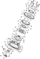
- FIG. 2 is a sectional view taken along line AA in FIG. 1.
- FIG. 2 is a sectional view taken along line BB in FIG.
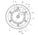
- It is a rear view of the electric power feeding plate provided to this embodiment.
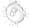
- It is a perspective view of the cover member provided for this embodiment.
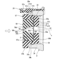
- It is the C section enlarged view of FIG.
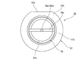
- It is a front view of the seal cap provided for this embodiment. It is a rear view of the seal cap.
- valve timing control device for an internal combustion engine according to the present invention
- the present invention is applied to the intake valve side.
- the valve timing control device is rotatably supported on a timing sprocket 1 that is a driving rotating body that is rotationally driven by a crankshaft of an internal combustion engine, and a cylinder head 01 via a bearing 02.
- the camshaft 2 rotated by the rotational force transmitted from the timing sprocket 1, the cover member 3 fixed to the chain cover 49 disposed at the front position of the timing sprocket 1, the timing sprocket 1 and the camshaft 2 And a phase changing mechanism 4 which is disposed between the two and changes the relative rotational phase of the two and two in accordance with the engine operating state.
- the timing sprocket 1 is formed integrally with an iron-based metal in an annular shape, and the inner peripheral surface is integrally provided on the outer periphery of the sprocket body 1a with a stepped diameter, and is wound outside the drawing.
- the gear part 1b which receives the rotational force from a crankshaft via this timing chain, and the internal-tooth structure part 19 integrally provided in the front-end side of the said sprocket main body 1a are comprised.
- the timing sprocket 1 has a single large-diameter ball bearing 43 interposed between a sprocket body 1a and a driven member 9 (described later) provided at the front end of the camshaft 2.
- the timing sprocket 1 and the camshaft 2 are supported by a ball bearing 43 so as to be relatively rotatable.
- the large-diameter ball bearing 43 includes an outer ring 43a, an inner ring 43b, and a ball 43c interposed between the two wheels 43a and 43b.
- the outer ring 43a is fixed to the inner peripheral side of the sprocket body 1a.
- the inner ring 43 b is fixed to the outer peripheral side of the driven member 9.
- the sprocket body 1a is formed with an annular groove-shaped outer ring fixing portion 60 opened on the camshaft 2 side on the inner peripheral side.
- the outer ring fixing portion 60 is formed in a stepped diameter shape so that the outer ring 43a of the large-diameter ball bearing 43 is press-fitted in the axial direction, and the outer ring 43a is positioned on one axial side. .
- the internal tooth component 19 is integrally provided on the outer peripheral side of the front end portion of the sprocket body 1a, is formed in a cylindrical shape extending forward of the phase changing mechanism 4, and has a plurality of wave shapes on the inner periphery.
- the inner teeth 19a are formed.
- annular female thread forming portion 6 integral with a motor housing 5 to be described later is disposed opposite to the front end side of the internal tooth constituting portion 19.
- annular holding plate 61 is disposed at the rear end of the sprocket body 1a opposite to the internal tooth component 19.
- the holding plate 61 is integrally formed of a metal plate material.
- the outer diameter is set to be substantially the same as the outer diameter of the sprocket body 1 a and the inner diameter is the same as that of the large-diameter ball bearing 43.
- the diameter is set smaller than the inner diameter of the outer ring 43a.
- the inner peripheral portion 61a of the holding plate 61 is disposed in contact with the outer end surface in the axial direction of the outer ring 43a. Further, a stopper convex portion 61b protruding inward in the radial direction, that is, in the central axis direction is integrally provided at a predetermined position on the inner peripheral edge of the inner peripheral portion 61a.
- the stopper convex portion 61b is formed in a substantially fan shape, and the tip edge 61c is formed in an arc shape along an arc-shaped inner peripheral surface of a stopper concave groove 2b described later.
- six bolt insertion holes 61d through which the respective bolts 7 are inserted are formed in the outer peripheral portion of the holding plate 61 at equal intervals in the circumferential direction.
- bolt insertion holes 1c and 61d are formed in the outer peripheral portions of the sprocket main body 1a (internal tooth constituting portion 19) and the holding plate 61, respectively, at substantially equal intervals in the circumferential direction.
- the female screw forming portion 6 is formed with six female screw holes 6a at positions corresponding to the bolt insertion holes 1c and 61d, and the timing sprocket 1 and the holding plate are formed by six bolts 7 inserted through these female screw holes 6a.
- 61 and the motor housing 5 are fastened together in the axial direction.
- the sprocket body 1a and the internal gear component 19 are configured as a casing for a speed reduction mechanism 8 to be described later.
- the outer diameters of the sprocket body 1a, the inner tooth component 19, the holding plate 61, and the female screw forming portion 6 are set to be substantially the same.
- the chain cover 49 extends in the vertical direction so as to cover the cylinder head 01 as the engine body and the chain outside the figure wound around the timing sprocket 1 on the front end side of the cylinder block outside the figure. Is fixed. Further, boss portions 49b are integrally formed at four locations in the circumferential direction of the annular wall 49a constituting the opening formed at a position corresponding to the phase changing mechanism 4, and each boss is formed from the annular wall 49a. A female screw hole 49c is formed over the inside of the portion 49b.
- the cover member 3 is integrally formed in a cup shape with an aluminum alloy material, and is disposed so as to cover the front end portion of the motor housing 5, and has a bulging shape.
- a cover main body 3a and an annular mounting flange 3b formed integrally with the outer peripheral edge on the opening side of the cover main body 3a are provided.
- a cup-shaped space 32 is defined between the inner surface 3 f of the cover member 3 and the outer surface of the front end portion of the motor housing 5.
- the cover body 3 a has a cylindrical wall 3 c that protrudes integrally along the axial direction on the outer peripheral side, and the cylindrical wall 3 c has a holding hole 3 d in the internal axial direction. It is formed through.
- a cylindrical portion 34 is provided so as to protrude parallel to the cylindrical wall 3c and along the axial direction.
- the cylindrical portion 34 has an upper end portion integrally coupled with a lower end portion of the cylindrical wall 3c, and a communication hole 35 that penetrates between the outside of the cover main body 3a and the space portion 32 is formed in the inner axial direction.
- a seal cap 56 as a vent plug is press-fitted and fixed inside the outer end.
- the mounting flange 3b is provided with four bosses 3e at approximately equal intervals in the circumferential direction (approximately 90 ° positions) at approximately equal intervals in the circumferential direction. As shown in FIG. 1, each boss portion 3e is formed with a bolt insertion hole 3g through which a bolt 54 screwed into each female screw hole 49d formed in the chain cover 49 is inserted. The cover member 3 is fixed to the chain cover 49 by 54.
- a large-diameter oil seal 50 is interposed between the inner peripheral surface of the stepped portion on the outer peripheral side of the cover body 3a and the outer peripheral surface of the motor housing 5.
- the large-diameter oil seal 50 is formed in a substantially U-shaped cross section, a core metal is embedded in the synthetic rubber base material, and an annular base on the outer peripheral side is the inner periphery of the cover member 3. It is fitted and fixed to a step ring portion 3h provided on the surface.
- the large-diameter oil seal 50 seals the space portion 32 in a liquid-tight manner so as to prevent the lubricating oil scattered mainly due to the rotational drive of the timing sprocket 1 from entering the space portion 32. It has become.
- the motor housing 5 includes a housing body 5a formed of a ferrous metal material in a bottomed cylindrical shape by press molding, a power feeding plate 11 that seals a front end opening of the housing body 5a, It has.
- the housing main body 5a has a disk-shaped partition wall 5b on the rear end side, and a large-diameter shaft insertion hole 5c through which an eccentric shaft portion 39, which will be described later, is inserted is formed substantially at the center of the partition wall 5b.
- a cylindrical extending portion 5d protruding in the axial direction of the camshaft 2 is integrally provided at the hole edge of the shaft insertion hole 5c.
- the female thread forming portion 6 is integrally provided on the outer peripheral side of the front end surface of the partition wall 5b.
- the camshaft 2 has two drive cams per cylinder for opening an intake valve (not shown) on the outer periphery, and the flange portion 2a is integrally provided at the front end.
- the flange portion 2a has an outer diameter set to be slightly larger than an outer diameter of a fixed end portion 9a of a driven member 9 to be described later, and after assembling each component, the outer peripheral portion of the front end surface Is arranged in contact with the axially outer end surface of the inner ring 43b of the large-diameter ball bearing 43. Further, the front end face of the flange portion 2a is coupled from the axial direction by the cam bolt 10 in a state of being in contact with the driven member 9 from the axial direction.
- stopper concave grooves 2b into which the stopper convex portions 61b of the holding plate 61 are engaged are formed on the outer periphery of the flange portion 2a along the circumferential direction.
- the stopper concave groove 2b is formed in a circular arc shape having a predetermined length in the circumferential direction, and both end edges of the stopper convex portion 61b rotated within this length range abut against the circumferential facing surfaces 2c and 2d, respectively.
- the relative rotational position of the camshaft 2 on the maximum advance angle side or the maximum retard angle side with respect to the timing sprocket 1 is regulated.
- the stopper convex portion 61b is disposed at a position closer to the camshaft 2 than a portion of the holding plate 61 fixed to the outer ring 43a of the large-diameter ball bearing 43 facing the outer side in the axial direction. 9 is not in contact with the fixed end 9a in the axial direction. Therefore, interference between the stopper convex portion 61b and the fixed end portion 9a can be sufficiently suppressed.
- the cam bolt 10 has an end surface of the head portion 10a that supports the inner ring of the small-diameter ball bearing 37 from the axial direction, and an inner shaft extending from the end portion of the camshaft 2 to the outer periphery of the shaft portion 10b.
- a male screw 10c is formed to be screwed onto the female screw formed in the direction.
- the driven member 9 is integrally formed of an iron-based metal, and as shown in FIG. 1, a disk-like fixed end portion 9a formed on the rear end side (camshaft 2 side), and the fixed end portion 9a.
- the rear end surface of the fixed end portion 9a is in contact with the front end surface of the flange portion 2a of the camshaft 2, and is fixed to the flange portion 2a by pressure contact with the axial force of the cam bolt 10 from the axial direction.
- the cylindrical portion 9b has an insertion hole 9d through which the shaft portion 10b of the cam bolt 10 is inserted, and a needle bearing 38 as a bearing member provided on the outer peripheral side. It has been.
- the retainer 41 is bent into a substantially L-shaped cross section forward from the front end of the outer peripheral portion of the fixed end portion 9a, and protrudes in the same direction as the cylindrical portion 9b. Is formed.
- the cylindrical tip portion 41a of the retainer 41 extends in the direction of the partition wall 5b of the motor housing 5 through an annular concave storage space 44 formed between the female screw forming portion 6 and the extending portion 5d. ing. Further, as shown in FIG. 1 and FIG. 2, a plurality of substantially rectangular roller holders that hold the plurality of rollers 48 in a freely rolling manner at substantially equal intervals in the circumferential direction of the cylindrical tip portion 41 a. Holes 41b are formed at equally spaced positions in the circumferential direction. The total number of the roller holding holes 41 b (rollers 48) is smaller than the total number of teeth of the internal teeth 19 a of the internal tooth component 19. As a result, the reduction ratio is obtained.
- the phase changing mechanism 4 includes the electric motor 12 disposed on the front end side of the cylindrical portion 9b of the driven member 9, a speed reducing mechanism 8 that reduces the rotational speed of the electric motor 12 and transmits the speed to the camshaft 2. Is mainly composed of
- the electric motor 12 is a brushed DC motor, the motor housing 5 being a yoke that rotates integrally with the timing sprocket 1, and the motor housing 5.
- a motor output shaft 13 that is rotatably provided, a pair of semicircular arc permanent magnets 14 and 15 that are stators fixed to the inner peripheral surface of the motor housing 5, and the power supply plate 11 are provided.
- the motor output shaft 13 is formed in a stepped cylindrical shape and functions as an armature, and has a large diameter portion 13a on the camshaft 2 side through a stepped portion 13c formed at a substantially central position in the axial direction, and the opposite side. And a small-diameter portion 13b.
- the large-diameter portion 13a has an iron core rotor 17 fixed to the outer periphery, and an eccentric shaft portion 39 constituting a part of the speed reduction mechanism 8 is integrally formed on the rear end side.
- the annular member 20 is press-fitted and fixed to the outer periphery of the small-diameter portion 13b, and a commutator 21 described later is press-fitted and fixed to the outer peripheral surface of the annular member 20 from the axial direction by the outer surface of the step portion 13c. Axial positioning is performed.
- the outer diameter of the annular member 20 is set to be substantially the same as the outer diameter of the large-diameter portion 13a, and the axial length is set slightly shorter than the small-diameter portion 13b.
- a plug body 55 that is supplied into the motor output shaft 13 and the eccentric shaft portion 39 and suppresses leakage of the lubricating oil for lubricating the bearings 37 and 38 to the outside. It is press-fitted and fixed.
- the iron core rotor 17 is formed of a magnetic material having a plurality of magnetic poles, and the outer peripheral side is configured as a bobbin having a slot around which the coil wire of the coil 18 is wound.
- the commutator 21 is formed in an annular shape by a conductive material, and the end of the coil wire from which the coil 18 is drawn is electrically connected to each segment divided into the same number as the number of poles of the iron core rotor 17. ing.
- the permanent magnets 14, 15 are formed in a cylindrical shape as a whole and have a plurality of magnetic poles in the circumferential direction, and the position in the axial direction is the power supply with respect to the axial center of the iron core rotor 17. It is offset on the plate 11 side. Accordingly, the front end portions of the permanent magnets 14 and 15 are arranged so as to overlap with switching brushes 25a and 25b described later provided on the commutator 21 and the power feeding plate 11 in the radial direction.
- the power supply plate 11 includes a disk-shaped rigid plate 16 (fixed plate) made of an iron-based metal material, and disk-shaped molds molded on both front and rear sides of the rigid plate 16. And a resin portion 22.
- the power feeding plate 11 is configured as a part of a power feeding mechanism for the electric motor 12.
- the rigid plate 16 is formed by caulking an annular stepped concave groove 5 e formed on the inner periphery of the front end portion of the motor housing 5 with an outer peripheral portion 16 a not covered with the resin portion 22.
- a shaft insertion hole 16b through which one end of the motor output shaft 13 and the like are inserted is formed through the center portion.
- the rigid plate 16 is formed by punching two holding holes 16c and 16d having different shapes at predetermined positions continuous to the inner peripheral edge of the shaft insertion hole 16b. Brush holders 23a and 23b, which will be described later, are fitted and held in the holding holes 16c and 16d.
- three U-shaped grooves 16e are formed at predetermined positions in the circumferential direction of the outer peripheral portion 16a so as to perform positioning in the circumferential direction with respect to the housing body 5a through a jig (not shown).
- the power feeding plate 11 is disposed inside the holding holes 16 c and 16 d of the rigid plate 16, and has a plurality of rivets 40 on the front end portion 22 a of the resin portion 22.
- Each of the front end surfaces is a pair of switching brushes 25a and 25b that are commutators that elastically contact the outer peripheral surface of the commutator 21 from the radial direction, and the front end portion 22a side of the resin portion 22 is exposed to the outer surface.
- the inner and outer double power supply slip rings 26a and 26b which are fixed by molding, are electrically connected to the switching brushes 25a and 25b and the slip rings 26a and 26b. Continue to harness 27a, and 27b, is provided. These and the power feeding plate 11 constitute a power feeding mechanism.
- the small slip ring 26a on the inner peripheral side and the large diameter slip ring 26b on the outer peripheral side are formed by punching a thin plate made of a copper material into an annular shape by pressing.
- a holding body 28 integrally molded with a synthetic resin material is fixed to the cover body 3a of the cover member 3.
- the holding body 28 is formed in a substantially crank shape when viewed from the side, and has a substantially bottomed cylindrical brush holding portion 28a inserted into the holding hole 3d of the cover member 3.
- the brush holding portion 28 a extends substantially in the horizontal direction (axial direction) and is parallel to the internal vertical position (inner and outer peripheral sides with respect to the axis of the motor housing 5).
- a pair of rectangular tube-shaped brush holders 29a and 29b are press-fitted and fixed in a pair of prismatic fixing holes formed in FIG.
- the power supply brushes 30a and 30b are held in the brush holders 29a and 29b so as to be slidable in the axial direction.
- the brush holding portion 28a is formed in the annular sealing member that elastically contacts the inner peripheral surface of the holding hole 3d in an annular fitting groove formed on the outer periphery of the base portion. 33 is fitted and held.
- the annular seal member 33 provides a liquid-tight seal between the space 32 and the outside of the cover member 3.
- Each of the brush holders 29a and 29b has an opening at the front and rear ends thereof, and the front ends of the power supply brushes 30a and 30b can be moved forward and backward from the opening on the front end side.
- One end of the pigtail harness (not shown) is connected to the rear end of each of the power supply brushes 30a and 30b via the opening by soldering.
- Each of the power supply brushes 30a and 30b is formed in a prismatic shape and set to a predetermined axial length, and each flat tip surface is in contact with each of the slip rings 26a and 26b from the axial direction. It has become.
- a pair of coil springs 42a and 42b for urging the power supply brushes 30a and 30b in the direction of the slip rings 26a and 26b are provided on the inner rear end sides of the brush holders 29a and 29b of the brush holding portion 28a. Is provided.
- the pair of power supply terminal pieces 31 and 31 are formed in a parallel and substantially crank shape along the vertical direction, and the terminals 31a and 31a on one side (lower end side) are exposed.
- the other side (upper end side) terminals 31b and 31b are provided so as to protrude into the fitting groove 28d of the connector portion 28b.
- the terminals 31a and 31a on the one side are arranged in contact with the upper surface of the bottom wall 28f, and the other ends of a pair of pigtail harnesses (not shown) are connected by soldering.
- each pigtail harness has a length that prevents the power supply brushes 30a and 30b from falling off the brush holders 29a and 29b even when the power supply brushes 30a and 30b are pushed out by the spring force of the coil springs 42a and 42b. Is set.
- the connector portion 28b is electrically connected to the control unit (not shown) via the male terminal by the other side terminals 31b and 31b facing the fitting groove 28d in which a male terminal (not shown) is inserted into the upper end portion. It is connected.
- the motor output shaft 13 and the eccentric shaft portion 39 are provided on the outer peripheral surface of the cylindrical portion 9b of the driven member 9 and the small-diameter ball bearing 37 provided on the outer peripheral surface of the shaft portion 10b of the cam bolt 10. And the needle bearing 38 arranged on the side in the axial direction.
- the needle bearing 38 includes a cylindrical retainer 38a press-fitted into the inner peripheral surface of the eccentric shaft portion 39, and a needle roller 38b, which is a plurality of rolling elements rotatably held inside the retainer 38a. Has been.
- the needle roller 38 b rolls on the outer peripheral surface of the cylindrical portion 9 b of the driven member 9.
- the small-diameter ball bearing 37 has an inner ring fixed between the front end edge of the cylindrical portion 9 b of the driven member 9 and the head 10 a of the cam bolt 10, while an outer ring has a step difference of the eccentric shaft portion 39. While being press-fitted and fixed to the inner peripheral surface of the diameter, the axial positioning is performed by contacting a step edge formed on the inner peripheral surface.
- the lubricating oil from the inside of the speed reduction mechanism 8 into the electric motor 12 is provided between the outer peripheral surface of the motor output shaft 13 (eccentric shaft portion 39) and the inner peripheral surface of the extending portion 5d of the motor housing 5, the lubricating oil from the inside of the speed reduction mechanism 8 into the electric motor 12 is provided.
- a small-diameter oil seal 46 is provided to prevent this leakage. The oil seal 46 separates the electric motor 12 and the speed reduction mechanism 8 with a sealing function.
- the control unit detects the current engine operating state based on information signals from various sensors such as a crank angle sensor, an air flow meter, a water temperature sensor, and an accelerator opening sensor (not shown), and performs engine control based on this information signal.
- the coil 18 is energized through the power supply brushes 30a, 30b, the slip rings 26a, 26b, the switching brushes 25a, 25b, the commutator 21, and the like to control the rotation of the motor output shaft 13, thereby reducing the speed reduction mechanism 8.
- the relative rotation phase of the camshaft 2 with respect to the timing sprocket 1 is controlled.
- the speed reduction mechanism 8 includes the eccentric shaft portion 39 that performs an eccentric rotational motion, a medium-diameter ball bearing 47 provided on the outer periphery of the eccentric shaft portion 39, and the medium-diameter ball.
- the roller 48 provided on the outer periphery of the bearing 47; the retainer 41 that allows the roller 48 to move in the radial direction while retaining the roller 48 in the rolling direction; and the driven member 9 that is integral with the retainer 41; Is mainly composed of
- the axial center Y of the cam surface 39a formed on the outer peripheral surface is slightly eccentric in the radial direction from the axial center X of the motor output shaft 13.
- the medium-diameter ball bearing 47 is disposed so as to be substantially overlapped at the radial position of the needle bearing 38, and includes an inner ring 47a, an outer ring 47b, and a ball 47c interposed between the wheels 47a and 47b. It is composed of The inner ring 47a is press-fitted and fixed to the outer peripheral surface of the eccentric shaft portion 39, whereas the outer ring 47b is in a free state without being fixed in the axial direction. That is, in the outer ring 47b, one end surface on the electric motor 12 side in the axial direction does not come into contact with any part, and the other end surface in the axial direction is between the inner side surface of the retainer 41 facing the minute end. One gap C is formed and is in a free state.
- the outer peripheral surface of the outer ring 47b is in contact with the outer peripheral surface of each roller 48 so as to be freely rotatable, and an annular second gap C1 is formed on the outer peripheral side of the outer ring 47b. Due to the second gap C1, the entire medium-diameter ball bearing 47 can move in the radial direction along with the eccentric rotation of the eccentric shaft portion 39, that is, can move eccentrically.
- Each of the rollers 48 is formed of an iron-based metal, and is fitted into the internal teeth 19a of the internal gear component 19 while moving in the radial direction along with the eccentric movement of the medium-diameter ball bearing 47.
- the roller holding hole 41b is caused to swing in the radial direction while being guided in the circumferential direction by both side edges.
- the inside of the speed reduction mechanism 8 is supplied with lubricating oil by lubricating oil supply means.
- This lubricating oil supply means is formed inside the bearing 02 of the cylinder head 01, and is formed in the oil supply passage through which the lubricating oil is supplied from a main oil gallery (not shown) and in the direction of the internal axis of the camshaft 2.
- An oil supply hole 51 communicating with the oil supply passage via a groove groove 51b, and an inner shaft direction of the driven member 9 is formed so that one end is open to the oil supply hole 51 and the other end is the
- the small-diameter oil hole 52 opened in the vicinity of the needle bearing 38 and the medium-diameter ball bearing 47, and an oil discharge hole (not shown) formed through the driven member 9 are also formed.
- this lubricating oil supply means lubricating oil is supplied and stays in the accommodation space 44, from which the medium-diameter ball bearing 47 and each roller 48 are lubricated, and further, the eccentric shaft portion 39 and the motor output shaft 13 It flows into the interior and is used to lubricate movable parts such as the needle bearing 38 and the small-diameter ball bearing 37.
- the lubricating oil staying in the housing space 44 is prevented from leaking into the motor housing 5 by the small diameter oil seal 46.
- the cylindrical portion 34 provided on the cover member 3 includes an annular locking convex portion 34a that is a locking portion on the inner periphery of the tip portion, and the locking portion.
- An annular locking recess 34b is integrally provided inside the projection 34a.
- the engaging protrusion 34 a is formed with an inner diameter substantially the same as the inner diameter d of the communication hole 35, while the engaging recess 34 b is formed with an inner diameter slightly larger than the inner diameter d of the communication hole 35.
- the protrusions 34a and the protrusions 34a are formed in a stepped shape.
- the communication hole 35 (cylindrical portion 34) is used for positioning work for adjusting the relative position between the hollow cylindrical motor output shaft 13 and the cover member 3 after the cover member 3 is assembled to the chain cover 49. It functions as a hole, and its axial center is formed substantially coaxially with the axial center X of a hollow cylindrical motor output shaft 13 to be described later, and its inner diameter d is slightly larger than the inner diameter of the motor output shaft 13. Is formed.
- the seal cap 56 is a cap body which is a bottomed cylindrical plug body formed in a substantially U-shaped longitudinal section and having a concave groove 57a formed substantially at the center of the outer surface. 57, a support portion 58 that is a fitting portion that is press-fitted into the concave groove 57a of the cap main body 57, and a bottom surface 57i of the concave groove 57a that is disposed and accommodated on the bottom surface 57i and the support portion 58. And a circular ventilation filter 59 held in a sandwiched state.
- the cap body 57 is integrally formed of an elastically deformable synthetic resin material, and is engaged with the engagement convex portion 34a of the cylindrical portion 34 on the outer peripheral surfaces of the bottom wall 57b and the outer peripheral wall 57c constituting the concave groove 57a.
- An annular engaging groove 57d is formed, and an annular engaging protrusion 57e that engages with the engaging recess 34b is integrally formed on the inner side in the axial direction of the engaging groove 57d.
- the concave groove 57a is formed with a circular first air hole 57f having a uniform inner diameter along the axial direction at substantially the center position of the bottom wall 57b and penetrating along the inner axial direction.
- An annular fitting groove 57g is formed on the inner peripheral surface.
- a flange-like protruding portion 57h is integrally formed on the outer peripheral surface front end side of the outer peripheral wall 57c, and the protruding portion 57h is formed when the cap body 57 is engaged with the front end opening of the communication hole 35. It serves as a stopper for preventing further engagement by abutting against the opening edge of the front end of the communication hole 35 in the axial direction.
- an escape groove 57k is formed in the upper end portion of the protruding portion 57h along the tangential direction so as to avoid interference with the lower end portion of the brush holding portion 28a.
- the support portion 58 is integrally formed in a substantially annular shape by an elastically deformable synthetic resin material, and has an axial width and thickness slightly smaller than the depth D of the concave groove 57a.
- a second vent hole 58a (a vent hole of the fitting portion) communicating with the first vent hole 57f is formed penetrating along the axial direction.
- the support 58 has an annular fitting protrusion 58b fitted and fixed to the fitting groove 57g of the cap main body 57 at the end of the outer peripheral surface on the concave groove bottom surface 57i side of the cap main body 57. It is provided integrally.
- a linear groove 58c is formed on the outer end surface of the support portion 58 along the diametrical direction to prevent erroneous assembly of the cap body 57 into the concave groove 57a.
- the second vent hole 58a is formed in a trumpet shape that expands from the outer end portion in the axial direction to the inner end portion on the first vent hole 57f side, and the passage portion 58d at the inner end portion is formed in a large diameter.
- the ventilation portion 58e at the outer end is formed in a small diameter, and by reducing the diameter of the ventilation portion 58e, intrusion of water, dust or the like from the outside is suppressed.
- the ventilation filter 59 is formed in a thin cloth-like disk shape that can be freely bent and deformed, and has an outer diameter smaller than the inner diameter of the concave groove bottom surface 57i of the cap body 57, and the whole is on the bottom surface 57i.
- the groove 57a of the main body 57 which is held horizontally, is inserted in advance and placed on the bottom surface 57i in this state, and in this state, the support portion 58 is press-fitted into the groove 57a.
- the bottom surface 57i and the front end surface 58f of the support portion 58 facing the bottom surface 57i are sandwiched and fixed.
- the ventilation filter 59 can pass air from the surface 59a on the support portion 58 side to the back surface 59b side on the concave groove bottom surface 57i side, but it does not pass from the back surface 59b side to the surface 59a side.
- a base material made of a material that suppresses permeation of liquid or dust is used.
- the coil 18 of the electric motor 12 is supplied from the control unit through the terminal pieces 31 and 31, the pigtail harness, the power supply brushes 30a and 30b, the slip rings 26a and 26b, and the like. Is energized. As a result, the motor output shaft 13 is rotationally driven, and the rotational force of this rotational force is transmitted to the camshaft 2 via the speed reduction mechanism 8.
- the rollers 48 are guided in the radial direction by the roller holding holes 41b of the retainer 41 for each rotation of the motor output shaft 13. It moves over the one internal tooth 19a of the internal tooth component 19 while rolling to another adjacent internal tooth 19a, and repeatedly contacts this in the circumferential direction. By the rolling contact of the rollers 48, the rotation of the motor output shaft 13 is decelerated and the rotational force is transmitted to the driven member 9.
- the reduction ratio at this time can be arbitrarily set according to the difference between the number of the inner teeth 19a and the number of rollers 48.
- the camshaft 2 rotates relative to the timing sprocket 1 in the forward and reverse directions and the relative rotational phase is converted, and the opening / closing timing of the intake valve is controlled to be advanced or retarded.
- the maximum position restriction (angular position restriction) of forward and reverse relative rotation of the camshaft 2 with respect to the timing sprocket 1 is such that each side surface of the stopper convex portion 61b is set to one of the opposing surfaces 2c and 2d of the stopper concave groove 2b. This is done by abutting.
- the opening / closing timing of the intake valve is converted to the maximum on the advance side or the retard side, and the fuel efficiency and output of the engine can be improved.
- the space 32 is sealed by the large-diameter oil seal 50 and the annular seal member 33.
- the seal cap 56 is provided on the cylindrical portion 34 of the cover member 3.
- Air can be quickly discharged through the first and second ventilation holes 57f and 58a and the ventilation filter 59.
- deformation and dropping of components such as the large-diameter oil seal 50 and the annular seal member 33 can be sufficiently suppressed.
- the ventilation filter 59 allows the air in the space portion 32 and the outside air outside the cover member 3 to pass therethrough, it can suppress the transmission of water, dust, etc. from the outside of the cover member 3. Intrusion of water and dust into the inside 32 can be suppressed.
- the seal cap 56 is pre-assembled with each component such as the cap body 57 before assembling the entire seal cap 56 into the communication hole 35.
- the cap body 57 is mounted.
- the inner end face 57j is placed horizontally on the upper surface of the base, and then the ventilation filter 59 is inserted into the groove 57a and placed on the bottom face 57i.
- the support portion 58 is pushed in with a finger against the elastic force and press-fitted into the inside from the front end opening of the concave groove 57a
- the fitting body 58b of the support portion 58 is elastically deformed while the cap body is deformed.
- the venting filter 59 is nipped and fixed between the bottom surface 57i of the concave groove 57a and the front end surface 58f of the support portion 58.
- the support portion 58 and the ventilation filter 59 can be fixed in the concave groove 57a with respect to the cap body 57, the assembling work of the support portion 58 and the ventilation filter 59 to the cap body 57 is easy. become.
- the bottom wall 57b of the cap body 57 is aligned with the front end opening of the communication hole 35, and is left as it is. If the center position of the outer end surface of the support portion 58, that is, the center position of the second ventilation hole 58a on the ventilation portion 58e side is pushed by the finger toward the bottom surface 57i of the groove 57a, the cylindrical projection 34 is deformed while the engagement projection 57e is deformed. At the same time, the engagement groove 57d is elastically locked to the locking projection 34a. As a result, the seal cap 56 can be easily and reliably attached to the front end opening of the communication hole 35 of the cylindrical portion 34 with one touch.
- a concave groove 57a is formed on the inner end side (electric motor 12 side) of the cap body 57, and the support portion 58 is fitted into the concave groove 57a from the inside.
- the concave groove 57a is formed on the electric motor 12 side. Since the support portion 58 is assembled by fitting into the concave groove 57a on the inner end side of the cap body 57 because the opening is directed to the operator, an operator can attach the cap body to the communication hole 35 when attaching to the communication hole 35. If the 57 is pushed into the communication hole 35 from the outside, the pressing force may cause the support portion 58 to come out of the concave groove 57a and drop out into the communication hole 35 (on the electric motor 12 side). That.
- seal cap 56 must be reassembled and attached, which may lead to a reduction in installation efficiency.
- a concave groove 57a is formed on the side opposite to the outer end side (electric motor 12) of the cap body 57, and the support portion 58 of the concave groove 57a is engaged and fixed from the outside.
- the center position of the support portion 58 is pushed from the outside to the concave groove 57a side by the finger. Regardless, the support portion 58 will not accidentally fall off from the cap body 57. As a result, the attaching operation of the seal cap 56 is facilitated, and the efficiency of the attaching operation can be improved.
- the ventilation filter 59 can be easily replaced.
- the brush holders 23a and 23b of the switching brushes 25a and 25b are fixed to the resin portion 22 in a state where the brush holders 23a and 23b are disposed in the thinned holding holes 16c and 16d of the rigid plate 16, respectively. That is, since the rigid plate 16 is arranged and fixed at substantially the center in the axial direction, the length of the power feeding mechanism in the axial direction can be shortened as much as possible. As a result, the entire apparatus can be reduced in the axial direction.
- the seal cap 56 is disposed radially inward from the inner and outer double power supply slip rings 26a and 26b, the power supply brushes 30a and 30b slide on the slip rings 26a and 26b. Even if abrasion powder is generated, clogging of the ventilation filter 59 can be suppressed without being easily applied to the seal cap 56.
- the present invention is not limited to the configuration of each of the above embodiments, and the structure of the cap body 57, the support portion 58, and the like can be further changed.
Landscapes
- Engineering & Computer Science (AREA)
- Power Engineering (AREA)
- General Engineering & Computer Science (AREA)
- Mechanical Engineering (AREA)
- Valve Device For Special Equipments (AREA)
Abstract
Description
〔第1実施形態〕
このバルブタイミング制御装置は、図1及び図2に示すように、内燃機関のクランクシャフトによって回転駆動する駆動回転体であるタイミングスプロケット1と、シリンダヘッド01上に軸受02を介して回転自在に支持され、前記タイミングスプロケット1から伝達された回転力によって回転するカムシャフト2と、タイミングスプロケット1の前方位置に配置されたチェーンカバー49に固定されたカバー部材3と、タイミングスプロケット1とカムシャフト2の間に配置されて、機関運転状態に応じて両者1,2の相対回転位相を変更する位相変更機構4と、を備えている。
〔本実施形態の作動〕
以下、本実施形態の作動について説明すると、まず、機関のクランクシャフトの回転駆動に伴ってタイミングチェーンを介してタイミングスプロケット1が回転して、その回転力が内歯構成部19と雌ねじ形成部6を介してモータハウジング5に伝達されて、該モータハウジング5が同期回転する。一方、前記内歯構成部19の回転力が、各ローラ48から保持器41及び従動部材9を経由してカムシャフト2に伝達される。これによって、カムシャフト2のカムが吸気弁を開閉作動させる。
Claims (12)
- 電動モータに通電することによってクランクシャフトに対するカムシャフトの相対回転位相を変更する内燃機関のバルブタイミング制御装置であって、
前記電動モータの少なくとも一部を覆うように設けられたカバー部材と、
前記電動モータとカバー部材のいずれか一方に設けられたスリップリングと、
前記電動モータとカバー部材のいずれか他方に設けられ、先端部が前記スリップリングに摺動して前記電動モータに給電する給電用ブラシと、
前記電動モータとカバー部材との間に形成されて、前記スリップリングと給電用ブラシの摺動部位が臨む空間部と、
前記カバー部材に設けられ、前記空間部とカバー部材の外部とを連通する連通孔と、
該連通孔に前記カバー部材の外部から圧入固定された通気用栓体と、
を備え、
前記通気用栓体は、軸方向に通気孔が貫通形成され、外周に前記連通孔の外側孔縁に係止する栓本体と、該栓本体の外端面側に形成された凹溝に嵌合する嵌合部と、前記凹溝の前記通気孔が臨む底面側に配置されて、前記栓本体と嵌合部との間に挟持状態に保持された通気用フィルタと、を有することを特徴とする内燃機関のバルブタイミング制御装置。 - 請求項1に記載の内燃機関のバルブタイミング制御装置において、
前記連通孔は内周に係止凸部を有し、
前記栓本体は外周に前記係止凸部に係合する係合突部を有することを特徴とする内燃機関のバルブタイミング制御装置。 - 請求項2に記載の内燃機関のバルブタイミング制御装置において、
前記嵌合部は外周に嵌合突部を有し、
前記栓本体の凹溝は底面側の内周に前記嵌合突部が嵌合する嵌合溝を有することを特徴とする内燃機関のバルブタイミング制御装置。 - 請求項3に記載の内燃機関のバルブタイミング制御装置において、
前記係止凸部と前記嵌合溝が前記通気用栓体の径方向に並んでいることを特徴とする内燃機関のバルブタイミング制御装置。 - 請求項1に記載の内燃機関のバルブタイミング制御装置において、
前記通気用フィルタは、前記空間部とカバー部材の外部と間の空気を透過可能で、かつ、前記カバー部材と空間部内との間での液体や塵芥の透過を抑制する材質によって形成されていることを特徴とする内燃機関のバルブタイミング制御装置。 - 請求項1に記載の内燃機関のバルブタイミング制御装置において、
前記栓本体の材質は弾性変形可能な合成樹脂であることを特徴とする内燃機関のバルブタイミング制御装置。 - 請求項1に記載の内燃機関のバルブタイミング制御装置において、
前記嵌合部の材質は弾性変形可能な合成樹脂であることを特徴とする内燃機関のバルブタイミング制御装置。 - 請求項1に記載の内燃機関のバルブタイミング制御装置において、
前記栓本体は、外周部に抜け止め用の突出部を有すると共に、該突出部が前記連通孔の外側孔縁部に軸方向から当接可能に形成されていることを特徴とする内燃機関のバルブタイミング制御装置。 - 請求項8に記載の内燃機関のバルブタイミング制御装置において、
前記カバー部材は、前記給電用ブラシを保持するブラシ保持部を有すると共に、
前記通気用栓体の突出部は、前記ブラシ保持部の外周部に対する逃げ溝が部分的に切欠形成されていることを特徴とする内燃機関のバルブタイミング制御装置。 - 請求項1に記載の内燃機関のバルブタイミング制御装置において、
前記嵌合部は、内部軸方向に前記栓本体の通気孔と連通する嵌合部の通気孔が貫通形成されていることを特徴とする内燃機関のバルブタイミング制御装置。 - 請求項10に記載の内燃機関のバルブタイミング制御装置において、
前記通気孔は外端面側の径が前記凹溝の底面側よりも小さいことを特徴とする内燃機関のバルブタイミング制御装置。 - 電動モータに通電することによってクランクシャフトに対するカムシャフトの相対回転位相を変更する内燃機関のバルブタイミング制御装置であって、
前記電動モータの少なくとも一部を覆うように設けられたカバー部材と、
前記カバー部材に設けられ、前記カバー部材の内部と外部を連通する連通孔と、
該連通孔に前記カバー部材の外部から圧入固定された通気用栓体と、
を備え、
前記通気用栓体は、軸方向に通気孔が貫通形成され、外周に前記連通孔の外側孔縁に係止する栓本体と、該栓本体の外端面側に形成された凹溝に嵌合する嵌合部と、前記嵌合部により前記凹溝内に保持される通気用フィルタと、を有することを特徴とする内燃機関のバルブタイミング制御装置。
Priority Applications (3)
| Application Number | Priority Date | Filing Date | Title |
|---|---|---|---|
| CN201580065069.5A CN107002519A (zh) | 2014-12-12 | 2015-11-27 | 内燃机的气门正时控制装置 |
| JP2016563615A JP6266810B2 (ja) | 2014-12-12 | 2015-11-27 | 内燃機関のバルブタイミング制御装置 |
| US15/534,160 US20180328239A1 (en) | 2014-12-12 | 2015-11-27 | Internal-combustion engine valve timing control device |
Applications Claiming Priority (2)
| Application Number | Priority Date | Filing Date | Title |
|---|---|---|---|
| JP2014251520 | 2014-12-12 | ||
| JP2014-251520 | 2014-12-12 |
Publications (1)
| Publication Number | Publication Date |
|---|---|
| WO2016093083A1 true WO2016093083A1 (ja) | 2016-06-16 |
Family
ID=56107273
Family Applications (1)
| Application Number | Title | Priority Date | Filing Date |
|---|---|---|---|
| PCT/JP2015/083384 Ceased WO2016093083A1 (ja) | 2014-12-12 | 2015-11-27 | 内燃機関のバルブタイミング制御装置 |
Country Status (4)
| Country | Link |
|---|---|
| US (1) | US20180328239A1 (ja) |
| JP (1) | JP6266810B2 (ja) |
| CN (1) | CN107002519A (ja) |
| WO (1) | WO2016093083A1 (ja) |
Families Citing this family (2)
| Publication number | Priority date | Publication date | Assignee | Title |
|---|---|---|---|---|
| JP6740938B2 (ja) * | 2017-03-15 | 2020-08-19 | 株式会社デンソー | 偏心揺動型減速装置 |
| CN117381498A (zh) * | 2023-10-23 | 2024-01-12 | 重庆渝江岚峰动力部件有限公司 | 一种圆盘铣夹具自动打开装置 |
Citations (5)
| Publication number | Priority date | Publication date | Assignee | Title |
|---|---|---|---|---|
| JPH046253U (ja) * | 1990-04-27 | 1992-01-21 | ||
| US5215312A (en) * | 1989-09-14 | 1993-06-01 | Siemens Aktiengesellschaft | Housing with a pressure-equalizing element which is retained water-tightly around the edges within a housing wall opening |
| JP2013113100A (ja) * | 2011-11-25 | 2013-06-10 | Honda Motor Co Ltd | モータドライバの取付構造 |
| JP2013167181A (ja) * | 2012-02-15 | 2013-08-29 | Hitachi Automotive Systems Ltd | 内燃機関のバルブタイミング制御装置 |
| JP2014157972A (ja) * | 2013-02-18 | 2014-08-28 | Denso Corp | 電子部品用収容部材、および、それを用いたバルブタイミング調整装置 |
Family Cites Families (2)
| Publication number | Priority date | Publication date | Assignee | Title |
|---|---|---|---|---|
| JP5976505B2 (ja) * | 2012-11-07 | 2016-08-23 | 日立オートモティブシステムズ株式会社 | 内燃機関のバルブタイミング制御装置 |
| JP5940002B2 (ja) * | 2013-02-14 | 2016-06-29 | 日立オートモティブシステムズ株式会社 | 内燃機関のバルブタイミング制御システム |
-
2015
- 2015-11-27 US US15/534,160 patent/US20180328239A1/en not_active Abandoned
- 2015-11-27 JP JP2016563615A patent/JP6266810B2/ja not_active Expired - Fee Related
- 2015-11-27 CN CN201580065069.5A patent/CN107002519A/zh active Pending
- 2015-11-27 WO PCT/JP2015/083384 patent/WO2016093083A1/ja not_active Ceased
Patent Citations (5)
| Publication number | Priority date | Publication date | Assignee | Title |
|---|---|---|---|---|
| US5215312A (en) * | 1989-09-14 | 1993-06-01 | Siemens Aktiengesellschaft | Housing with a pressure-equalizing element which is retained water-tightly around the edges within a housing wall opening |
| JPH046253U (ja) * | 1990-04-27 | 1992-01-21 | ||
| JP2013113100A (ja) * | 2011-11-25 | 2013-06-10 | Honda Motor Co Ltd | モータドライバの取付構造 |
| JP2013167181A (ja) * | 2012-02-15 | 2013-08-29 | Hitachi Automotive Systems Ltd | 内燃機関のバルブタイミング制御装置 |
| JP2014157972A (ja) * | 2013-02-18 | 2014-08-28 | Denso Corp | 電子部品用収容部材、および、それを用いたバルブタイミング調整装置 |
Also Published As
| Publication number | Publication date |
|---|---|
| US20180328239A1 (en) | 2018-11-15 |
| JP6266810B2 (ja) | 2018-01-24 |
| JPWO2016093083A1 (ja) | 2017-06-01 |
| CN107002519A (zh) | 2017-08-01 |
Similar Documents
| Publication | Publication Date | Title |
|---|---|---|
| JP5976505B2 (ja) | 内燃機関のバルブタイミング制御装置 | |
| KR101655225B1 (ko) | 내연기관의 밸브 타이밍 제어장치 | |
| KR101710251B1 (ko) | 내연 기관의 가변 밸브 장치 | |
| JP2013167181A (ja) | 内燃機関のバルブタイミング制御装置 | |
| KR101624776B1 (ko) | 내연 기관의 밸브 타이밍 제어 장치 및 마개체의 제거 방법 | |
| JP5978111B2 (ja) | 内燃機関のバルブタイミング制御装置 | |
| JP6174160B2 (ja) | 内燃機関のバルブタイミング制御装置 | |
| JP6125094B2 (ja) | 内燃機関のバルブタイミング制御装置 | |
| JP6266810B2 (ja) | 内燃機関のバルブタイミング制御装置 | |
| JP5693312B2 (ja) | 内燃機関のバルブタイミング制御装置 | |
| JP6030781B2 (ja) | 内燃機関のバルブタイミング制御装置 | |
| KR101710232B1 (ko) | 내연 기관의 밸브 타이밍 제어 장치 및 이 밸브 타이밍 제어 장치에 이용되는 급전 기구 | |
| JP2016048053A (ja) | 内燃機関のバルブタイミング制御装置及びバルブタイミング制御システム | |
| JP5873523B2 (ja) | 内燃機関のバルブタイミング制御装置 | |
| JP5993352B2 (ja) | 内燃機関の可変動弁装置及びローラ減速機構 | |
| JP6347764B2 (ja) | 内燃機関のバルブタイミング制御装置及びこの装置の組立方法 | |
| JP6274900B2 (ja) | 内燃機関のバルブタイミング制御装置 | |
| KR101646314B1 (ko) | 내연 기관의 밸브 타이밍 제어 장치 및 이 밸브 타이밍 제어 장치에 이용되는 커버 부재 | |
| JP2015178822A (ja) | 内燃機関のバルブタイミング制御装置 | |
| JP6720319B2 (ja) | 内燃機関のバルブタイミング制御装置と該バルブタイミング制御装置の製造方法及びブラシ保持部材 | |
| JP2015206308A (ja) | 内燃機関のバルブタイミング制御装置 |
Legal Events
| Date | Code | Title | Description |
|---|---|---|---|
| 121 | Ep: the epo has been informed by wipo that ep was designated in this application |
Ref document number: 15868015 Country of ref document: EP Kind code of ref document: A1 |
|
| ENP | Entry into the national phase |
Ref document number: 2016563615 Country of ref document: JP Kind code of ref document: A |
|
| WWE | Wipo information: entry into national phase |
Ref document number: 15534160 Country of ref document: US |
|
| NENP | Non-entry into the national phase |
Ref country code: DE |
|
| 122 | Ep: pct application non-entry in european phase |
Ref document number: 15868015 Country of ref document: EP Kind code of ref document: A1 |