WO2016092824A1 - 車両制御装置 - Google Patents
車両制御装置 Download PDFInfo
- Publication number
- WO2016092824A1 WO2016092824A1 PCT/JP2015/006103 JP2015006103W WO2016092824A1 WO 2016092824 A1 WO2016092824 A1 WO 2016092824A1 JP 2015006103 W JP2015006103 W JP 2015006103W WO 2016092824 A1 WO2016092824 A1 WO 2016092824A1
- Authority
- WO
- WIPO (PCT)
- Prior art keywords
- vehicle
- tire
- data
- friction coefficient
- braking distance
- Prior art date
- Legal status (The legal status is an assumption and is not a legal conclusion. Google has not performed a legal analysis and makes no representation as to the accuracy of the status listed.)
- Ceased
Links
Images




Classifications
-
- B—PERFORMING OPERATIONS; TRANSPORTING
- B60—VEHICLES IN GENERAL
- B60W—CONJOINT CONTROL OF VEHICLE SUB-UNITS OF DIFFERENT TYPE OR DIFFERENT FUNCTION; CONTROL SYSTEMS SPECIALLY ADAPTED FOR HYBRID VEHICLES; ROAD VEHICLE DRIVE CONTROL SYSTEMS FOR PURPOSES NOT RELATED TO THE CONTROL OF A PARTICULAR SUB-UNIT
- B60W30/00—Purposes of road vehicle drive control systems not related to the control of a particular sub-unit, e.g. of systems using conjoint control of vehicle sub-units
- B60W30/14—Adaptive cruise control
- B60W30/16—Control of distance between vehicles, e.g. keeping a distance to preceding vehicle
-
- B—PERFORMING OPERATIONS; TRANSPORTING
- B60—VEHICLES IN GENERAL
- B60C—VEHICLE TYRES; TYRE INFLATION; TYRE CHANGING; CONNECTING VALVES TO INFLATABLE ELASTIC BODIES IN GENERAL; DEVICES OR ARRANGEMENTS RELATED TO TYRES
- B60C19/00—Tyre parts or constructions not otherwise provided for
-
- B—PERFORMING OPERATIONS; TRANSPORTING
- B60—VEHICLES IN GENERAL
- B60C—VEHICLE TYRES; TYRE INFLATION; TYRE CHANGING; CONNECTING VALVES TO INFLATABLE ELASTIC BODIES IN GENERAL; DEVICES OR ARRANGEMENTS RELATED TO TYRES
- B60C99/00—Subject matter not provided for in other groups of this subclass
-
- B—PERFORMING OPERATIONS; TRANSPORTING
- B60—VEHICLES IN GENERAL
- B60T—VEHICLE BRAKE CONTROL SYSTEMS OR PARTS THEREOF; BRAKE CONTROL SYSTEMS OR PARTS THEREOF, IN GENERAL; ARRANGEMENT OF BRAKING ELEMENTS ON VEHICLES IN GENERAL; PORTABLE DEVICES FOR PREVENTING UNWANTED MOVEMENT OF VEHICLES; VEHICLE MODIFICATIONS TO FACILITATE COOLING OF BRAKES
- B60T7/00—Brake-action initiating means
- B60T7/12—Brake-action initiating means for automatic initiation; for initiation not subject to will of driver or passenger
- B60T7/22—Brake-action initiating means for automatic initiation; for initiation not subject to will of driver or passenger initiated by contact of vehicle, e.g. bumper, with an external object, e.g. another vehicle, or by means of contactless obstacle detectors mounted on the vehicle
-
- B—PERFORMING OPERATIONS; TRANSPORTING
- B60—VEHICLES IN GENERAL
- B60T—VEHICLE BRAKE CONTROL SYSTEMS OR PARTS THEREOF; BRAKE CONTROL SYSTEMS OR PARTS THEREOF, IN GENERAL; ARRANGEMENT OF BRAKING ELEMENTS ON VEHICLES IN GENERAL; PORTABLE DEVICES FOR PREVENTING UNWANTED MOVEMENT OF VEHICLES; VEHICLE MODIFICATIONS TO FACILITATE COOLING OF BRAKES
- B60T8/00—Arrangements for adjusting wheel-braking force to meet varying vehicular or ground-surface conditions, e.g. limiting or varying distribution of braking force
- B60T8/17—Using electrical or electronic regulation means to control braking
-
- B—PERFORMING OPERATIONS; TRANSPORTING
- B60—VEHICLES IN GENERAL
- B60T—VEHICLE BRAKE CONTROL SYSTEMS OR PARTS THEREOF; BRAKE CONTROL SYSTEMS OR PARTS THEREOF, IN GENERAL; ARRANGEMENT OF BRAKING ELEMENTS ON VEHICLES IN GENERAL; PORTABLE DEVICES FOR PREVENTING UNWANTED MOVEMENT OF VEHICLES; VEHICLE MODIFICATIONS TO FACILITATE COOLING OF BRAKES
- B60T8/00—Arrangements for adjusting wheel-braking force to meet varying vehicular or ground-surface conditions, e.g. limiting or varying distribution of braking force
- B60T8/17—Using electrical or electronic regulation means to control braking
- B60T8/172—Determining control parameters used in the regulation, e.g. by calculations involving measured or detected parameters
-
- B—PERFORMING OPERATIONS; TRANSPORTING
- B60—VEHICLES IN GENERAL
- B60T—VEHICLE BRAKE CONTROL SYSTEMS OR PARTS THEREOF; BRAKE CONTROL SYSTEMS OR PARTS THEREOF, IN GENERAL; ARRANGEMENT OF BRAKING ELEMENTS ON VEHICLES IN GENERAL; PORTABLE DEVICES FOR PREVENTING UNWANTED MOVEMENT OF VEHICLES; VEHICLE MODIFICATIONS TO FACILITATE COOLING OF BRAKES
- B60T8/00—Arrangements for adjusting wheel-braking force to meet varying vehicular or ground-surface conditions, e.g. limiting or varying distribution of braking force
- B60T8/17—Using electrical or electronic regulation means to control braking
- B60T8/172—Determining control parameters used in the regulation, e.g. by calculations involving measured or detected parameters
- B60T8/1725—Using tyre sensors, e.g. Sidewall Torsion sensors [SWT]
-
- B—PERFORMING OPERATIONS; TRANSPORTING
- B60—VEHICLES IN GENERAL
- B60T—VEHICLE BRAKE CONTROL SYSTEMS OR PARTS THEREOF; BRAKE CONTROL SYSTEMS OR PARTS THEREOF, IN GENERAL; ARRANGEMENT OF BRAKING ELEMENTS ON VEHICLES IN GENERAL; PORTABLE DEVICES FOR PREVENTING UNWANTED MOVEMENT OF VEHICLES; VEHICLE MODIFICATIONS TO FACILITATE COOLING OF BRAKES
- B60T8/00—Arrangements for adjusting wheel-braking force to meet varying vehicular or ground-surface conditions, e.g. limiting or varying distribution of braking force
- B60T8/17—Using electrical or electronic regulation means to control braking
- B60T8/173—Eliminating or reducing the effect of unwanted signals, e.g. due to vibrations or electrical noise
-
- B—PERFORMING OPERATIONS; TRANSPORTING
- B60—VEHICLES IN GENERAL
- B60W—CONJOINT CONTROL OF VEHICLE SUB-UNITS OF DIFFERENT TYPE OR DIFFERENT FUNCTION; CONTROL SYSTEMS SPECIALLY ADAPTED FOR HYBRID VEHICLES; ROAD VEHICLE DRIVE CONTROL SYSTEMS FOR PURPOSES NOT RELATED TO THE CONTROL OF A PARTICULAR SUB-UNIT
- B60W10/00—Conjoint control of vehicle sub-units of different type or different function
- B60W10/04—Conjoint control of vehicle sub-units of different type or different function including control of propulsion units
- B60W10/06—Conjoint control of vehicle sub-units of different type or different function including control of propulsion units including control of combustion engines
-
- B—PERFORMING OPERATIONS; TRANSPORTING
- B60—VEHICLES IN GENERAL
- B60W—CONJOINT CONTROL OF VEHICLE SUB-UNITS OF DIFFERENT TYPE OR DIFFERENT FUNCTION; CONTROL SYSTEMS SPECIALLY ADAPTED FOR HYBRID VEHICLES; ROAD VEHICLE DRIVE CONTROL SYSTEMS FOR PURPOSES NOT RELATED TO THE CONTROL OF A PARTICULAR SUB-UNIT
- B60W10/00—Conjoint control of vehicle sub-units of different type or different function
- B60W10/18—Conjoint control of vehicle sub-units of different type or different function including control of braking systems
- B60W10/184—Conjoint control of vehicle sub-units of different type or different function including control of braking systems with wheel brakes
-
- B—PERFORMING OPERATIONS; TRANSPORTING
- B60—VEHICLES IN GENERAL
- B60W—CONJOINT CONTROL OF VEHICLE SUB-UNITS OF DIFFERENT TYPE OR DIFFERENT FUNCTION; CONTROL SYSTEMS SPECIALLY ADAPTED FOR HYBRID VEHICLES; ROAD VEHICLE DRIVE CONTROL SYSTEMS FOR PURPOSES NOT RELATED TO THE CONTROL OF A PARTICULAR SUB-UNIT
- B60W30/00—Purposes of road vehicle drive control systems not related to the control of a particular sub-unit, e.g. of systems using conjoint control of vehicle sub-units
- B60W30/14—Adaptive cruise control
-
- B—PERFORMING OPERATIONS; TRANSPORTING
- B60—VEHICLES IN GENERAL
- B60W—CONJOINT CONTROL OF VEHICLE SUB-UNITS OF DIFFERENT TYPE OR DIFFERENT FUNCTION; CONTROL SYSTEMS SPECIALLY ADAPTED FOR HYBRID VEHICLES; ROAD VEHICLE DRIVE CONTROL SYSTEMS FOR PURPOSES NOT RELATED TO THE CONTROL OF A PARTICULAR SUB-UNIT
- B60W30/00—Purposes of road vehicle drive control systems not related to the control of a particular sub-unit, e.g. of systems using conjoint control of vehicle sub-units
- B60W30/14—Adaptive cruise control
- B60W30/143—Speed control
-
- B—PERFORMING OPERATIONS; TRANSPORTING
- B60—VEHICLES IN GENERAL
- B60W—CONJOINT CONTROL OF VEHICLE SUB-UNITS OF DIFFERENT TYPE OR DIFFERENT FUNCTION; CONTROL SYSTEMS SPECIALLY ADAPTED FOR HYBRID VEHICLES; ROAD VEHICLE DRIVE CONTROL SYSTEMS FOR PURPOSES NOT RELATED TO THE CONTROL OF A PARTICULAR SUB-UNIT
- B60W30/00—Purposes of road vehicle drive control systems not related to the control of a particular sub-unit, e.g. of systems using conjoint control of vehicle sub-units
- B60W30/18—Propelling the vehicle
- B60W30/18009—Propelling the vehicle related to particular drive situations
- B60W30/18109—Braking
-
- B—PERFORMING OPERATIONS; TRANSPORTING
- B60—VEHICLES IN GENERAL
- B60W—CONJOINT CONTROL OF VEHICLE SUB-UNITS OF DIFFERENT TYPE OR DIFFERENT FUNCTION; CONTROL SYSTEMS SPECIALLY ADAPTED FOR HYBRID VEHICLES; ROAD VEHICLE DRIVE CONTROL SYSTEMS FOR PURPOSES NOT RELATED TO THE CONTROL OF A PARTICULAR SUB-UNIT
- B60W40/00—Estimation or calculation of non-directly measurable driving parameters for road vehicle drive control systems not related to the control of a particular sub unit, e.g. by using mathematical models
- B60W40/02—Estimation or calculation of non-directly measurable driving parameters for road vehicle drive control systems not related to the control of a particular sub unit, e.g. by using mathematical models related to ambient conditions
- B60W40/06—Road conditions
- B60W40/068—Road friction coefficient
-
- B—PERFORMING OPERATIONS; TRANSPORTING
- B60—VEHICLES IN GENERAL
- B60W—CONJOINT CONTROL OF VEHICLE SUB-UNITS OF DIFFERENT TYPE OR DIFFERENT FUNCTION; CONTROL SYSTEMS SPECIALLY ADAPTED FOR HYBRID VEHICLES; ROAD VEHICLE DRIVE CONTROL SYSTEMS FOR PURPOSES NOT RELATED TO THE CONTROL OF A PARTICULAR SUB-UNIT
- B60W40/00—Estimation or calculation of non-directly measurable driving parameters for road vehicle drive control systems not related to the control of a particular sub unit, e.g. by using mathematical models
- B60W40/12—Estimation or calculation of non-directly measurable driving parameters for road vehicle drive control systems not related to the control of a particular sub unit, e.g. by using mathematical models related to parameters of the vehicle itself, e.g. tyre models
-
- B—PERFORMING OPERATIONS; TRANSPORTING
- B60—VEHICLES IN GENERAL
- B60W—CONJOINT CONTROL OF VEHICLE SUB-UNITS OF DIFFERENT TYPE OR DIFFERENT FUNCTION; CONTROL SYSTEMS SPECIALLY ADAPTED FOR HYBRID VEHICLES; ROAD VEHICLE DRIVE CONTROL SYSTEMS FOR PURPOSES NOT RELATED TO THE CONTROL OF A PARTICULAR SUB-UNIT
- B60W40/00—Estimation or calculation of non-directly measurable driving parameters for road vehicle drive control systems not related to the control of a particular sub unit, e.g. by using mathematical models
- B60W40/12—Estimation or calculation of non-directly measurable driving parameters for road vehicle drive control systems not related to the control of a particular sub unit, e.g. by using mathematical models related to parameters of the vehicle itself, e.g. tyre models
- B60W40/13—Load or weight
-
- B—PERFORMING OPERATIONS; TRANSPORTING
- B60—VEHICLES IN GENERAL
- B60C—VEHICLE TYRES; TYRE INFLATION; TYRE CHANGING; CONNECTING VALVES TO INFLATABLE ELASTIC BODIES IN GENERAL; DEVICES OR ARRANGEMENTS RELATED TO TYRES
- B60C19/00—Tyre parts or constructions not otherwise provided for
- B60C2019/004—Tyre sensors other than for detecting tyre pressure
-
- B—PERFORMING OPERATIONS; TRANSPORTING
- B60—VEHICLES IN GENERAL
- B60T—VEHICLE BRAKE CONTROL SYSTEMS OR PARTS THEREOF; BRAKE CONTROL SYSTEMS OR PARTS THEREOF, IN GENERAL; ARRANGEMENT OF BRAKING ELEMENTS ON VEHICLES IN GENERAL; PORTABLE DEVICES FOR PREVENTING UNWANTED MOVEMENT OF VEHICLES; VEHICLE MODIFICATIONS TO FACILITATE COOLING OF BRAKES
- B60T2201/00—Particular use of vehicle brake systems; Special systems using also the brakes; Special software modules within the brake system controller
- B60T2201/02—Active or adaptive cruise control system; Distance control
- B60T2201/024—Collision mitigation systems
-
- B—PERFORMING OPERATIONS; TRANSPORTING
- B60—VEHICLES IN GENERAL
- B60T—VEHICLE BRAKE CONTROL SYSTEMS OR PARTS THEREOF; BRAKE CONTROL SYSTEMS OR PARTS THEREOF, IN GENERAL; ARRANGEMENT OF BRAKING ELEMENTS ON VEHICLES IN GENERAL; PORTABLE DEVICES FOR PREVENTING UNWANTED MOVEMENT OF VEHICLES; VEHICLE MODIFICATIONS TO FACILITATE COOLING OF BRAKES
- B60T2210/00—Detection or estimation of road or environment conditions; Detection or estimation of road shapes
- B60T2210/10—Detection or estimation of road conditions
- B60T2210/12—Friction
-
- B—PERFORMING OPERATIONS; TRANSPORTING
- B60—VEHICLES IN GENERAL
- B60W—CONJOINT CONTROL OF VEHICLE SUB-UNITS OF DIFFERENT TYPE OR DIFFERENT FUNCTION; CONTROL SYSTEMS SPECIALLY ADAPTED FOR HYBRID VEHICLES; ROAD VEHICLE DRIVE CONTROL SYSTEMS FOR PURPOSES NOT RELATED TO THE CONTROL OF A PARTICULAR SUB-UNIT
- B60W50/00—Details of control systems for road vehicle drive control not related to the control of a particular sub-unit, e.g. process diagnostic or vehicle driver interfaces
- B60W2050/0001—Details of the control system
- B60W2050/0043—Signal treatments, identification of variables or parameters, parameter estimation or state estimation
- B60W2050/0057—Frequency analysis, spectral techniques or transforms
-
- B—PERFORMING OPERATIONS; TRANSPORTING
- B60—VEHICLES IN GENERAL
- B60W—CONJOINT CONTROL OF VEHICLE SUB-UNITS OF DIFFERENT TYPE OR DIFFERENT FUNCTION; CONTROL SYSTEMS SPECIALLY ADAPTED FOR HYBRID VEHICLES; ROAD VEHICLE DRIVE CONTROL SYSTEMS FOR PURPOSES NOT RELATED TO THE CONTROL OF A PARTICULAR SUB-UNIT
- B60W2400/00—Indexing codes relating to detected, measured or calculated conditions or factors
-
- B—PERFORMING OPERATIONS; TRANSPORTING
- B60—VEHICLES IN GENERAL
- B60W—CONJOINT CONTROL OF VEHICLE SUB-UNITS OF DIFFERENT TYPE OR DIFFERENT FUNCTION; CONTROL SYSTEMS SPECIALLY ADAPTED FOR HYBRID VEHICLES; ROAD VEHICLE DRIVE CONTROL SYSTEMS FOR PURPOSES NOT RELATED TO THE CONTROL OF A PARTICULAR SUB-UNIT
- B60W2420/00—Indexing codes relating to the type of sensors based on the principle of their operation
- B60W2420/10—Transducer, e.g. piezoelectric elements
-
- B—PERFORMING OPERATIONS; TRANSPORTING
- B60—VEHICLES IN GENERAL
- B60W—CONJOINT CONTROL OF VEHICLE SUB-UNITS OF DIFFERENT TYPE OR DIFFERENT FUNCTION; CONTROL SYSTEMS SPECIALLY ADAPTED FOR HYBRID VEHICLES; ROAD VEHICLE DRIVE CONTROL SYSTEMS FOR PURPOSES NOT RELATED TO THE CONTROL OF A PARTICULAR SUB-UNIT
- B60W2422/00—Indexing codes relating to the special location or mounting of sensors
- B60W2422/70—Indexing codes relating to the special location or mounting of sensors on the wheel or the tyre
-
- B—PERFORMING OPERATIONS; TRANSPORTING
- B60—VEHICLES IN GENERAL
- B60W—CONJOINT CONTROL OF VEHICLE SUB-UNITS OF DIFFERENT TYPE OR DIFFERENT FUNCTION; CONTROL SYSTEMS SPECIALLY ADAPTED FOR HYBRID VEHICLES; ROAD VEHICLE DRIVE CONTROL SYSTEMS FOR PURPOSES NOT RELATED TO THE CONTROL OF A PARTICULAR SUB-UNIT
- B60W2520/00—Input parameters relating to overall vehicle dynamics
- B60W2520/10—Longitudinal speed
-
- B—PERFORMING OPERATIONS; TRANSPORTING
- B60—VEHICLES IN GENERAL
- B60W—CONJOINT CONTROL OF VEHICLE SUB-UNITS OF DIFFERENT TYPE OR DIFFERENT FUNCTION; CONTROL SYSTEMS SPECIALLY ADAPTED FOR HYBRID VEHICLES; ROAD VEHICLE DRIVE CONTROL SYSTEMS FOR PURPOSES NOT RELATED TO THE CONTROL OF A PARTICULAR SUB-UNIT
- B60W2530/00—Input parameters relating to vehicle conditions or values, not covered by groups B60W2510/00 or B60W2520/00
- B60W2530/20—Tyre data
-
- B—PERFORMING OPERATIONS; TRANSPORTING
- B60—VEHICLES IN GENERAL
- B60W—CONJOINT CONTROL OF VEHICLE SUB-UNITS OF DIFFERENT TYPE OR DIFFERENT FUNCTION; CONTROL SYSTEMS SPECIALLY ADAPTED FOR HYBRID VEHICLES; ROAD VEHICLE DRIVE CONTROL SYSTEMS FOR PURPOSES NOT RELATED TO THE CONTROL OF A PARTICULAR SUB-UNIT
- B60W2552/00—Input parameters relating to infrastructure
- B60W2552/40—Coefficient of friction
-
- B—PERFORMING OPERATIONS; TRANSPORTING
- B60—VEHICLES IN GENERAL
- B60W—CONJOINT CONTROL OF VEHICLE SUB-UNITS OF DIFFERENT TYPE OR DIFFERENT FUNCTION; CONTROL SYSTEMS SPECIALLY ADAPTED FOR HYBRID VEHICLES; ROAD VEHICLE DRIVE CONTROL SYSTEMS FOR PURPOSES NOT RELATED TO THE CONTROL OF A PARTICULAR SUB-UNIT
- B60W2554/00—Input parameters relating to objects
- B60W2554/80—Spatial relation or speed relative to objects
- B60W2554/801—Lateral distance
-
- B—PERFORMING OPERATIONS; TRANSPORTING
- B60—VEHICLES IN GENERAL
- B60W—CONJOINT CONTROL OF VEHICLE SUB-UNITS OF DIFFERENT TYPE OR DIFFERENT FUNCTION; CONTROL SYSTEMS SPECIALLY ADAPTED FOR HYBRID VEHICLES; ROAD VEHICLE DRIVE CONTROL SYSTEMS FOR PURPOSES NOT RELATED TO THE CONTROL OF A PARTICULAR SUB-UNIT
- B60W2710/00—Output or target parameters relating to a particular sub-units
- B60W2710/06—Combustion engines, Gas turbines
- B60W2710/0605—Throttle position
-
- B—PERFORMING OPERATIONS; TRANSPORTING
- B60—VEHICLES IN GENERAL
- B60W—CONJOINT CONTROL OF VEHICLE SUB-UNITS OF DIFFERENT TYPE OR DIFFERENT FUNCTION; CONTROL SYSTEMS SPECIALLY ADAPTED FOR HYBRID VEHICLES; ROAD VEHICLE DRIVE CONTROL SYSTEMS FOR PURPOSES NOT RELATED TO THE CONTROL OF A PARTICULAR SUB-UNIT
- B60W2710/00—Output or target parameters relating to a particular sub-units
- B60W2710/18—Braking system
-
- B—PERFORMING OPERATIONS; TRANSPORTING
- B60—VEHICLES IN GENERAL
- B60W—CONJOINT CONTROL OF VEHICLE SUB-UNITS OF DIFFERENT TYPE OR DIFFERENT FUNCTION; CONTROL SYSTEMS SPECIALLY ADAPTED FOR HYBRID VEHICLES; ROAD VEHICLE DRIVE CONTROL SYSTEMS FOR PURPOSES NOT RELATED TO THE CONTROL OF A PARTICULAR SUB-UNIT
- B60W2720/00—Output or target parameters relating to overall vehicle dynamics
- B60W2720/10—Longitudinal speed
- B60W2720/106—Longitudinal acceleration
-
- B—PERFORMING OPERATIONS; TRANSPORTING
- B60—VEHICLES IN GENERAL
- B60W—CONJOINT CONTROL OF VEHICLE SUB-UNITS OF DIFFERENT TYPE OR DIFFERENT FUNCTION; CONTROL SYSTEMS SPECIALLY ADAPTED FOR HYBRID VEHICLES; ROAD VEHICLE DRIVE CONTROL SYSTEMS FOR PURPOSES NOT RELATED TO THE CONTROL OF A PARTICULAR SUB-UNIT
- B60W2754/00—Output or target parameters relating to objects
- B60W2754/10—Spatial relation or speed relative to objects
- B60W2754/30—Longitudinal distance
Definitions
- the present disclosure relates to a vehicle control device that performs acceleration / deceleration control of a vehicle so as to avoid a collision with a preceding vehicle or the like.
- ACC adaptive cruise control
- PCS pre-crash safety system
- the ACC adjusts the inter-vehicle distance with the preceding vehicle according to the traveling speed, and performs acceleration / deceleration control of the vehicle so as to avoid a collision between the preceding vehicle and the host vehicle (see, for example, Patent Document 1).
- the collision damage reduction brake system compares the distance of the obstacle with the preceding vehicle and the braking distance, warns the driver, and generates a braking force to avoid collision between the obstacle and the vehicle. Thus, acceleration / deceleration control of the vehicle is performed.
- the coefficient of friction ⁇ between the tire and the road surface is reduced, for example, when the road surface ⁇ is low and the road surface ⁇ is low, such as a snowy road or a frozen road, or when tire wear occurs.
- the grip force decreases and the braking distance increases.
- the braking distance can be extended when the tire air pressure is reduced or the ground contact load of the wheel is excessive.
- the vehicle acceleration / deceleration control is performed on the assumption that the friction coefficient ⁇ between the tire and the road surface is a high value, there is a possibility that accurate control cannot be performed.
- an appropriate inter-vehicle distance cannot be maintained.
- one of the objects of the present disclosure is to provide a vehicle control device that can more appropriately perform acceleration / deceleration control of a vehicle based on a change in a friction coefficient ⁇ between a tire and a road surface. There is to do.
- a vehicle control device includes a vibration detection unit that is attached to a rear surface of a tread of a tire provided on a wheel of the vehicle, and that outputs a detection signal according to the magnitude of tire vibration.
- a tire-side device having a signal processing unit that generates ⁇ data that is data indicating a friction coefficient between a tire and a road surface by signal processing a detection signal, and a transmitter that transmits ⁇ data
- a receiver that receives ⁇ data transmitted from the transmitter, a friction coefficient estimation unit that estimates a friction coefficient from the ⁇ data, a braking distance acquisition unit that acquires a braking distance of the vehicle based on the friction coefficient, and a braking distance
- a travel control unit including an acceleration / deceleration control unit that performs acceleration / deceleration control of the vehicle.
- the friction coefficient between the tire and the road surface is transmitted from the tire side device to the vehicle side device, and the vehicle acceleration / deceleration control is performed according to the friction coefficient.
- the braking distance is estimated according to the friction coefficient ⁇ , and acceleration / deceleration control of the vehicle is performed according to the braking distance. For this reason, it becomes possible to change the timing of acceleration / deceleration according to the braking distance estimated according to the friction coefficient.
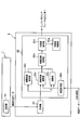
- FIG. 1A is a diagram illustrating a block configuration of a tire-side device of the vehicle control device according to the first embodiment.
- FIG. 1B is a diagram illustrating a block configuration of a vehicle-side device of the vehicle control device according to the first embodiment.
- FIG. 2 is a schematic cross-sectional view of a tire to which a tire side device is attached.
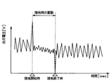
- FIG. 3 is an output voltage waveform diagram of the vibration power generation element during tire rotation.
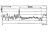
- FIG. 4A is a diagram showing a change in the output voltage of the vibration power generation element when traveling on a high ⁇ road surface having a relatively large road surface friction coefficient (hereinafter referred to as ⁇ ) like an asphalt road.
- FIG. 4B is a diagram showing a change in the output voltage of the vibration power generation element when traveling on a low ⁇ road surface where the road surface ⁇ is relatively small like an icy road.
- FIG. 5 is a diagram showing the result of frequency analysis of the output voltage during the grounding section when traveling on a high ⁇ road surface and when traveling on a low ⁇ road surface.
- FIG. 6 is a diagram showing the relationship between the friction coefficient ⁇ , the ground load, and the braking distance.
- FIG. 7 is a diagram showing the relationship between the inter-vehicle distance between the preceding vehicle and the host vehicle and the braking start position according to the change in the friction coefficient ⁇ .
- a vehicle control apparatus 100 according to the present embodiment will be described with reference to FIGS.
- the vehicle control apparatus 100 according to the present embodiment estimates a road surface condition during traveling based on vibrations on a ground contact surface of a tire provided on each wheel of the vehicle, and performs acceleration / deceleration control of the vehicle based on the estimation result. Used as
- the vehicle control device 100 has a tire-side device 1 provided on the tire side and a vehicle-side device 2 provided on the vehicle body side.
- the vehicle control device 100 includes data indicating the friction coefficient ⁇ between the tire and the running road surface from the tire side device 1 (hereinafter referred to as ⁇ data) and data regarding the contact time corresponding to the tire contact length (hereinafter referred to as ground contact). Long data).
- the vehicle control device 100 receives the ⁇ data and the contact length data transmitted from the tire side device 1 by the vehicle side device 2, estimates the friction coefficient ⁇ and the contact length based on the data, and sets the braking distance. Acquire and perform acceleration / deceleration control based on the acquired braking distance.
- the tire side device 1 and the vehicle side device 2 are configured as follows.
- the tire-side device 1 is configured to include a vibration power generation element 11, a power supply circuit 12, a signal processing circuit unit 13, and a transmitter 14, and as shown in FIG. Provided on the back side of the tread 31.
- the vibration power generation element 11 outputs a detection signal corresponding to the vibration in the direction in contact with the circular orbit drawn by the tire side device 1 when the tire 3 rotates, that is, in the tire tangential direction (direction of arrow X in FIG. 2).
- the vibration energy is converted into electric energy, and the power source of the tire side device 1 is generated based on the vibration energy. ing.
- the vibration power generation element 11 is disposed so as to generate power with respect to vibration in the tire tangential direction.
- an electrostatic induction type power generation element for example, an electrostatic induction type power generation element (electret), a piezoelectric element, a friction type, a magnetostriction type, or an electromagnetic induction type element can be applied.
- other devices such as an acceleration sensor may be used as long as the detection signal corresponding to the vibration in the tire tangential direction not taking into account the power generation application is output.
- an electrostatic induction type power generation element when used as the vibration power generation element 11, if the upper electrode charged positively by electrostatic induction is vibrated in the horizontal direction with respect to the lower electrode having a negative charge, Electricity is generated by changing the electric charge due to electrical induction and generating electromotive force. Based on such power generation by the vibration power generation element 11, the power source of the tire side device 1 is generated, and a detection signal corresponding to the magnitude of vibration in the tire tangential direction is generated.
- the vibration power generation element 11 when the vehicle equipped with the vehicle control device 100 travels, vibrations occur in the tread 31 of the tire 3 due to various factors such as the rotational movement of the tire 3 and the unevenness of the road surface.
- this vibration is transmitted to the vibration power generation element 11, power generation by the vibration power generation element 11 is performed, and when this vibration is transmitted to the power supply circuit 12, a power source for the tire side device 1 is generated.
- the signal processing circuit uses the output voltage of the vibration power generation element 11 as a detection signal representing the magnitude of vibration in the tire tangential direction. I tell it to the part 13.
- the output voltage of the vibration power generation element 11 is an alternating voltage because the upper electrode reciprocates due to vibration.
- the power supply circuit 12 is a circuit for storing power based on the output voltage of the vibration power generation element 11 to generate a power source and supplying power to the signal processing circuit unit 13 and the transmitter 14. 16 is provided.
- the rectifier circuit 15 is a known circuit that converts an alternating voltage output from the vibration power generation element 11 into a direct current.
- the AC voltage output from the vibration power generation element 11 is DC converted by the rectifier circuit 15 and output to the power storage circuit 16.
- the rectifier circuit 15 may be a full-wave rectifier circuit or a half-wave rectifier circuit.
- the accumulator circuit 16 is a circuit for accumulating the DC voltage applied from the rectifier circuit 15, and is constituted by a capacitor or the like.
- the output voltage of the vibration power generation element 11 is stored in the power storage circuit 16 via the rectifier circuit 15, and the voltage stored here is used as a power source to the signal processing circuit unit 13 and the transmitter 14 provided in the tire side device 1. Power is being supplied. Further, since the power supply circuit 12 includes the power storage circuit 16, when the vibration power generation element 11 is generating excessive power, the surplus is stored, and when the power generation amount is insufficient, the shortage is stored. It comes to be able to compensate.
- the signal processing circuit unit 13 is a part corresponding to the signal processing unit, and uses the output voltage of the vibration power generation element 11 as a detection signal representing vibration data in the tire tangential direction, and processes this detection signal to thereby determine the road surface condition. It is responsible for obtaining the data it represents and communicating it to the transmitter 14. That is, the signal processing circuit unit 13 is based on the time change of the output voltage of the vibration power generation element 11 and the grounding section of the vibration power generation element 11 when the tire 3 rotates (that is, the vibration power generation element 11 of the tread 31 of the tire 3). The section in which the portion corresponding to the arrangement location is grounded on the road surface) is extracted.
- the high frequency component included in the detection signal in the ground contact section of the vibration power generation element 11 represents the road surface condition
- the high frequency component is extracted and data representing the road surface condition is generated based on the extracted high frequency component.
- the signal processing circuit unit 13 measures the ground contact time of the vibration power generation element 11 during rotation of the tire 3 based on the time change of the output voltage of the vibration power generation element 11. Since the ground contact time of the vibration power generation element 11 becomes data related to the ground contact length on the ground contact surface of the tire 3, data representing the ground contact time is transmitted to the transmitter 14.
- the signal processing circuit unit 13 is configured by a known microcomputer including a CPU, a ROM, a RAM, an I / O, and the like, and performs the above processing according to a program stored in the ROM.
- the signal processing circuit unit 13 includes a peak detection unit 13a, a grounding time measurement unit 13b, and a high-frequency level calculation unit 13c as functional units that perform these processes.
- the peak detector 13a detects the peak value of the detection signal represented by the output voltage of the vibration power generation element 11.
- the output voltage waveform of the vibration power generation element 11 during tire rotation is, for example, the waveform shown in FIG.
- the output voltage of the vibration power generation element 11 reaches the maximum value at the start of grounding when the portion corresponding to the arrangement position of the vibration power generation element 11 of the tread 31 starts to ground as the tire 3 rotates.
- the peak detector 13a detects the start of grounding at which the output voltage of the vibration power generation element 11 takes a maximum value as the timing of the first peak value. Further, as shown in FIG.
- the portion of the tread 31 corresponding to the position where the vibration power generation element 11 is disposed is grounded from the state where the vibration power generation element 11 is not grounded.
- Output voltage takes the minimum value.
- the peak detector 13a detects the end of grounding when the output voltage of the vibration power generation element 11 takes a minimum value as the timing of the second peak value.
- the reason why the vibration power generation element 11 takes the peak value at the above timing is as follows. That is, when the portion of the tread 31 corresponding to the placement location of the vibration power generation element 11 comes into contact with the rotation of the tire 3, the portion of the tire 3 that has been substantially cylindrical in the vicinity of the vibration power generation element 11 is It is pressed and deformed into a flat shape. By receiving the impact at this time, the output voltage of the vibration power generation element 11 takes the first peak value. Further, when the portion of the tread 31 corresponding to the place where the vibration power generation element 11 is disposed is separated from the grounding surface as the tire 3 rotates, the tire 3 is released from pressing in the vicinity of the vibration power generation element 11 and is planar. To return to a substantially cylindrical shape.
- the output voltage of the vibration power generation element 11 takes the second peak value.
- the vibration power generation element 11 takes the first and second peak values when the grounding starts and when the grounding ends, respectively.
- the sign of the output voltage is also opposite.
- the peak detection unit 13a extracts detection signal data including the timings of the first and second peak values and transmits them to the ground contact time measurement unit 13b.
- the detection signal data including the timing of the first and second peak values indicates the detection signal itself during a predetermined period including the period from the first peak value to the second peak value.
- the time setting for a predetermined period including the period from the first peak value to the second peak value can be set to, for example, one rotation of the tire. For the period of one rotation of the tire, assuming that the vehicle speed at which the tire 3 is overloaded is to be determined, for example, when the vehicle speed range is 40 to 120 km / h or less, data of at least one rotation of the tire is included in the speed range. It is time to enter.
- a time for example, 250 ms in which the tire makes one revolution or more at a minimum speed of 40 km / h is set. Further, it may be from the timing when the first peak value is reached to the timing when the first peak value is next set.
- the detection signal data including the timings of the first and second peak values are extracted and transmitted to the contact time measuring unit 13b by the peak detection unit 13a, but the first and second peak values are obtained. Only the data relating to the timing may be transmitted to the contact time measuring unit 13b.
- the peak detection unit 13a obtains the first and second peak values
- the ground detection section of the vibration power generation element 11 is extracted by extracting the period between the first peak value and the second peak value
- the high frequency level calculator 13c is informed that it is in the grounding section.
- the detection signal data including the timings of the first and second peak values may be extracted by the peak detection unit 13a and transmitted to the high frequency level calculation unit 13c, or the first and second peak values may be transmitted.
- the data related to the timing obtained may be transmitted to the high frequency level calculation unit 13c.
- the peak detector 13a sends a transmission trigger to the transmitter 14 at this timing.
- the transmitter 14 transmits ground length data created by a ground time measuring unit 13b described later and ⁇ data created by the high frequency level calculating unit 13c. In this way, data transmission by the transmitter 14 is not always performed, but only when the vibration power generation element 11 is grounded, so that power consumption can be reduced.
- the grounding time measuring unit 13b measures the grounding time of the vibration power generation element 11 based on the data transmitted from the peak detecting unit 13a, and the measured grounding time is data indicating the grounding length.
- the data is transmitted to the transmitter 14 as data.
- the contact time measurement unit 13b measures the time interval between the timing of the first peak value and the timing of the second peak value from the data transmitted from the peak detection unit 13a. Thereby, the grounding time of the vibration power generation element 11 is measured.
- the transmitted data includes a plurality of first peak values and second peak values
- the timing of the smallest one of the second peak values and the timing of the first peak value immediately before the second peak value are included. You may measure the time interval between.
- the maximum value is detected as the first peak value.
- a minimum value is detected from a certain time after the timing of the maximum value, for example, a time shorter than one rotation of the tire of 120 km / h and longer than a contact time assumed at 40 km / h (for example, 30 ms). It detects as a 2nd peak value.
- the time difference between the timing at which the first peak value is reached and the timing at which the second peak value is reached can be set as the ground contact time.
- the high frequency level calculation unit 13c calculates the level of the high frequency component caused by the vibration of the tire 3 included in the output voltage of the vibration power generation element 11 during the period. To do. Then, the high-frequency level calculation unit 13c transmits the calculation result to the transmitter 14 as ⁇ data.
- the level of the high-frequency component is calculated as an index representing the friction coefficient ⁇ . The reason will be described with reference to FIGS. 4A, 4B and 5.
- FIG. 4A shows changes in the output voltage of the vibration power generation element 11 when the road surface ⁇ is traveling on a high ⁇ road surface having a relatively large road surface ⁇ such as an asphalt road and the friction coefficient ⁇ between the tire 3 and the road surface is high.
- 4B shows a change in the output voltage of the vibration power generation element 11 when the road surface ⁇ is traveling on a low ⁇ road surface having a relatively small road surface, such as a frozen road, and the friction coefficient ⁇ between the tire 3 and the road surface is low. Is shown.
- the first and second peak values appear at the beginning and end of the grounding section, that is, at the start and end of grounding of the vibration power generation element 11, regardless of the road surface ⁇ .
- the output voltage of the vibration power generation element 11 changes due to the influence of the friction coefficient ⁇ between the tire 3 and the road surface. For example, when the friction coefficient ⁇ is low, such as when traveling on a low ⁇ road surface, fine high-frequency vibration due to slip of the tire 3 is superimposed on the output voltage. Such a fine high-frequency signal due to the slip of the tire 3 is not superposed when the friction coefficient ⁇ is high, such as when traveling on a high ⁇ road surface.
- the frequency analysis of the output voltage in the grounding section is performed for each of the cases where the friction coefficient ⁇ is high and low, the result shown in FIG. 5 is obtained. That is, in the low frequency range, the level is high when the friction coefficient ⁇ is high or low, but in the high frequency range of 1 kHz or higher, the level is higher when the friction coefficient ⁇ is low than when it is high. become. For this reason, the level of the high frequency component of the output voltage of the vibration power generation element 11 is an index representing the road surface condition.
- the level of the high frequency component can be calculated by extracting the high frequency component from the output voltage of the vibration power generation element and integrating the extracted high frequency component during the grounding section.
- the high frequency components of the frequency bands fa to fb that are assumed to change according to the road surface condition and the road surface ⁇ are extracted by filtering or the like, and the voltages of the high frequency components of the frequency bands fa to fb extracted by the frequency analysis are obtained.
- Integrate For example, a capacitor (not shown) is charged. In this way, the amount of charge is higher when the friction coefficient ⁇ is higher than when traveling on a high ⁇ road surface, compared to when the friction coefficient ⁇ is low such as when traveling on a low ⁇ road surface. Become more. Using this charge amount as ⁇ data, the friction coefficient ⁇ can be estimated such that the road surface ⁇ is lower as the charge amount indicated by the ⁇ data is larger.
- the transmitter 14 transmits the contact length data and ⁇ data transmitted from the contact time measurement unit 13b and the high frequency level calculation unit 13c to the vehicle side device 2.
- Communication between the transmitter 14 and the receiver 21 included in the vehicle-side device 2 can be performed by a known short-range wireless communication technology such as Bluetooth (registered trademark).
- Bluetooth registered trademark
- each data is transmitted from the transmitter 14 by transmitting a transmission trigger from the peak detector 13a when the grounding of the vibration power generation element 11 is completed. It is supposed to be sent. In this way, data transmission by the transmitter 14 is not always performed, but only when the vibration power generation element 11 is grounded, so that power consumption can be reduced.
- each data is sent together with wheel specific identification information (hereinafter referred to as ID information) provided in advance for each tire 3 provided in the vehicle.
- ID information wheel specific identification information
- the position of each wheel can be specified by a well-known wheel position detecting device that detects where the wheel is attached to the vehicle. Therefore, by transmitting each data together with the ID information to the vehicle side device 2, it is possible to identify which wheel. Whether it is data can be determined.
- the vehicle side device 2 receives the contact length data and ⁇ data transmitted from the tire side device 1, and performs various processes based on these data, thereby performing various controls by the ACC and the collision damage reducing brake system. Do. Specifically, the vehicle side device 2 is configured to include a receiver 21 and a travel control unit 22.
- the receiver 21 is a device for receiving the contact length data and ⁇ data transmitted by the tire side device 1. Each data received by the receiver 21 is sequentially output to the traveling control unit 22 every time it is received.
- the traveling control unit 22 is configured by a known microcomputer including a CPU, a ROM, a RAM, an I / O, and the like, and performs various controls by the ACC and the collision damage reduction brake system according to a program stored in the ROM.
- the traveling control unit 22 is illustrated as a common unit that performs control of the ACC, the collision damage reduction brake system, and the like, but may be configured separately.
- the traveling control unit 22 includes a vehicle speed acquisition unit 22a, a calculation unit 22b, a friction coefficient estimation unit 22c, a ground load calculation unit 22d, a braking distance acquisition unit 22e, an acceleration / deceleration command unit 22f, and an acceleration / deceleration control unit 22g. Have.
- the vehicle speed acquisition unit 22a acquires vehicle speed data calculated by an in-vehicle ECU (electronic control unit) based on detection signals of a vehicle speed sensor and a wheel speed sensor through CAN (Controller Area Network) communication that is an in-vehicle network, The vehicle speed is acquired.
- an in-vehicle ECU electronic control unit
- CAN Controller Area Network
- the calculation unit 22b calculates an inter-vehicle distance and a relative speed difference and detects a pre-collision time (hereinafter referred to as TTC (Time to Colligion)) that is a time taken until the vehicle collides with a preceding vehicle. Since the calculation method of the inter-vehicle distance and the relative speed difference and the calculation method of the TTC are well-known, the description is omitted here, but the inter-vehicle distance and the relative speed difference with the preceding vehicle are calculated using, for example, a laser radar. In addition, the TTC is detected based on the inter-vehicle distance and the relative speed difference.
- TTC Time to Colligion
- the friction coefficient estimator 22c estimates the friction coefficient ⁇ based on the magnitude of the high-frequency level integrated voltage value indicated by the ⁇ data.
- the absolute value of the friction coefficient ⁇ may be estimated, or the magnitude of the friction coefficient ⁇ may be estimated.
- the friction coefficient ⁇ is estimated to be lower as the integrated voltage value indicated by the ⁇ data is larger.
- the determination threshold value is set, and the magnitude comparison between the integrated voltage value and the determination threshold value is performed. In this way, it can be estimated that the friction coefficient ⁇ is low when the integrated voltage value is larger than the determination threshold, and the friction coefficient ⁇ is high when the integral voltage value is small.
- the contact load calculation unit 22d calculates the contact load of the tire 3 based on the contact length data. Specifically, the contact load calculation unit 22d calculates the contact length of the tire 3 from the data representing the contact time sent from the tire side device 1 and the vehicle speed data acquired by the vehicle speed acquisition unit 22a. The contact length of the tire 3 is calculated by multiplying the vehicle speed and the contact time. For example, when the vehicle speed is 60 km / h and the contact time is 6 msec, the contact length can be calculated as 10 cm by multiplying them. Since the contact load corresponding to the contact length corresponding to the tire 3 is determined, the contact load corresponding to the calculated contact length is calculated.
- the braking distance acquisition unit 22e acquires the braking distance based on the friction coefficient ⁇ and the ground load obtained as described above.
- the braking distance is basically determined according to the friction coefficient ⁇ and the relative speed difference, and further increases as the wheel ground load increases.
- the relationship between the friction coefficient ⁇ and the braking distance when there is a predetermined relative vehicle speed difference is the relationship shown in FIG. 6, and the braking distance is shortened as the friction coefficient ⁇ increases. And this relationship shifts to the direction where braking distance extends, so that a ground contact load becomes large.
- the braking distance acquisition unit 22e stores a map showing the relationship of FIG. 6 or a function equation showing this relationship for each relative speed difference, and using this map or function equation, the friction coefficient obtained as described above is stored.
- Equation 1 L is a braking distance
- V is a relative speed difference
- ⁇ is a friction coefficient
- K is a coefficient set in accordance with the ground load.
- the acceleration / deceleration command unit 22f issues a command related to acceleration / deceleration control in the ACC and the collision damage reduction brake system based on the estimated value of the braking distance transmitted from the braking distance acquisition unit 22e, the inter-vehicle distance detected by the calculation unit 22b, and TTC. Do. For example, when the inter-vehicle distance is equal to or less than the braking distance, a deceleration command is issued in order to avoid a collision with the preceding vehicle. Further, when the inter-vehicle distance is greater than the braking distance and the possibility of collision with the preceding vehicle is low, an acceleration command is issued.
- the acceleration / deceleration control unit 22g performs various controls for accelerating / decelerating the vehicle based on the command of the acceleration / deceleration command unit 22f.
- the acceleration / deceleration control unit 22g is composed of, for example, an engine ECU or a brake ECU, and the engine ECU performs engine control according to a command from the acceleration / deceleration command unit 22f to generate acceleration, and the brake ECU performs brake control.
- the brake ECU drives a motor provided in the brake actuator to operate the pump, and controls various solenoid valves to generate a braking force. generate.
- each part which comprises the traveling control part 22 demonstrated here is comprised so that information exchange is possible mutually through CAN (Controller Area Network) communication which is a vehicle-mounted network, for example.
- CAN Controller Area Network
- the friction coefficient ⁇ between the tire 3 and the road surface is transmitted from the tire side apparatus 1 to the vehicle side apparatus 2, and ACC and collision are performed according to the friction coefficient ⁇ .
- the vehicle acceleration / deceleration control is performed in the damage reduction brake system. Specifically, the braking distance is estimated according to the friction coefficient ⁇ , and acceleration / deceleration control of the vehicle is performed according to the braking distance. Therefore, the acceleration / deceleration timing can be changed according to the braking distance estimated according to the friction coefficient ⁇ , and the vehicle acceleration / deceleration control can be performed more appropriately. In particular, when acquiring the braking distance, the braking distance corresponding to the vehicle state can be obtained more by acquiring the grounding load of the wheel.
- the braking distance is increased.
- the timing at which the inter-vehicle distance becomes equal to or less than the braking distance is earlier, and the deceleration can be generated at an earlier timing.
- more appropriate vehicle acceleration / deceleration control is performed based on the change in the friction coefficient ⁇ . Is possible.
- control is also performed in which the driver is warned at a stage prior to commanding deceleration, that is, a distance between vehicles longer than the distance between vehicles where deceleration starts.
- the threshold of the inter-vehicle distance that sets the timing of warning to the driver can also be changed according to the friction coefficient ⁇ . Therefore, when the friction coefficient ⁇ is low, it is possible to give a warning to the driver at an earlier timing, and it is possible to further improve traveling safety.
- the friction coefficient ⁇ set here indicates not only the road surface ⁇ but also the friction coefficient between the tire 3 and the road surface, that is, the grip force. Therefore, in addition to the change of the road surface ⁇ , the tire wear is taken into consideration. It is the value. Therefore, even when the braking distance is extended, such as when the road surface ⁇ is low or when the ground contact load of the wheel is excessive, it is possible to maintain a safer inter-vehicle distance and further improve driving safety. It becomes possible.
- the tire-side device 1 sends the contact length data to the vehicle-side device 2 in addition to the ⁇ data, and is obtained from the contact length data in addition to the friction coefficient ⁇ between the tire 3 and the road surface obtained from the ⁇ data.
- the braking distance is obtained by taking into account the wheel's ground contact load. This makes it possible to obtain a more accurate braking distance in consideration of the ground contact load.
- the braking distance may be acquired based on at least the friction coefficient ⁇ between the tire 3 and the road surface obtained from the ⁇ data.
Landscapes
- Engineering & Computer Science (AREA)
- Mechanical Engineering (AREA)
- Transportation (AREA)
- Automation & Control Theory (AREA)
- Physics & Mathematics (AREA)
- Mathematical Physics (AREA)
- Chemical & Material Sciences (AREA)
- Combustion & Propulsion (AREA)
- Regulating Braking Force (AREA)
- Control Of Driving Devices And Active Controlling Of Vehicle (AREA)
- Tires In General (AREA)
Abstract
タイヤ側装置(1)から車両側装置(2)に対してタイヤ(3)と路面との摩擦係数(μ)を伝え、摩擦係数(μ)に応じてアダプティブコントロール(ACC)や衝突被害軽減ブレーキシステムにおける車両の加減速制御を行う。具体的には、摩擦係数(μ)に応じて制動距離を推定し、この制動距離に応じて車両の加減速制御を行う。これにより、摩擦係数(μ)に応じて推定された制動距離に応じて加減速のタイミングを変えることが可能となり、より適切に車両の加減速制御を行うことが可能となる。
Description
本出願は、2014年12月12日に出願された日本国特許出願2014-251943号に基づくものであり、その開示をここに参照により援用する。
本開示は、先行車両などとの衝突を回避するように車両の加減速制御を行う車両制御装置に関するものである。
従来より、先行車両との衝突を回避するように車両の加減速制御を行うものとして、アダプティブクルーズコントロール(以下、ACCという)や衝突被害軽減ブレーキシステム(例えば、プリクラッシュセーフティシステム(PCS:登録商標))がある。ACCは、先行車両との車間距離を走行速度に応じて調整し、先行車両と自車両との衝突を回避するように車両の加減速制御を行う(例えば特許文献1参照)。衝突被害軽減ブレーキシステムは、先行車両などの障害物との距離と制動距離とを比較し、運転者に警告を行ったり、ブレーキ力を発生させることで障害物と自車両との衝突を回避するように車両の加減速制御を行う。
上記したACCや衝突被害軽減ブレーキシステムでは、タイヤと路面との間の摩擦係数μ、つまりグリップ力が高い値であること(例えば、μ=0.8)を前提として車両の加減速制御を行っている。
しかしながら、例えば雪道や凍結路のように走行路面の路面μが低い低μ路面である場合やタイヤ摩耗が生じた場合のように、タイヤと路面との間の摩擦係数μが低下しているとき、グリップ力が低下して制動距離が伸びることになる。また、タイヤ空気圧が低下していたり、車輪の接地荷重が過大である場合にも、同様に、制動距離が伸び得る。これらの場合、タイヤと路面との間の摩擦係数μが高い値であることを前提として車両の加減速制御を行うと、的確な制御が行えない可能性がある。例えば、ACCや衝突被害軽減ブレーキシステムにおいては、適切な車間距離を保てない可能性がある。
上記点に鑑みて、本開示の目的の一つは、タイヤと路面との間の摩擦係数μの変化に基づいて、より適切に車両の加減速制御を行うことが可能な車両制御装置を提供することにある。
本開示の一観点の車両制御装置は、車両における車輪に備えられたタイヤのトレッドの裏面に取り付けられ、タイヤの振動の大きさに応じた検出信号を出力する振動検出部と、振動検出部の検出信号を信号処理してタイヤと路面との間の摩擦係数を示すデータであるμデータを生成する信号処理部と、μデータを送信する送信機と、を有するタイヤ側装置を備えていると共に、送信機から送信されたμデータを受信する受信機と、μデータから摩擦係数を推定する摩擦係数推定部、摩擦係数に基づいて車両の制動距離を取得する制動距離取得部および制動距離に応じて車両の加減速制御を行うことを行う加減速制御部を含む走行制御部と、を有する車両側装置を備えている。
このように、タイヤ側装置から車両側装置に対してタイヤと路面との摩擦係数を伝え、摩擦係数に応じて車両の加減速制御を行うようにしている。具体的には、摩擦係数μに応じて制動距離を推定し、この制動距離に応じて車両の加減速制御を行っている。このため、摩擦係数に応じて推定された制動距離に応じて加減速のタイミングを変えることが可能となる。
本開示についての上記および他の目的、特徴や利点は、添付図面を参照した下記詳細な説明から、より明確になる。添付図面において、
図1Aは、第1実施形態にかかる車両制御装置のタイヤ側装置のブロック構成を示した図である。
図1Bは、第1実施形態にかかる車両制御装置の車両側装置のブロック構成を示した図である。
図2は、タイヤ側装置が取り付けられたタイヤの断面模式図である。
図3は、タイヤ回転時における振動発電素子の出力電圧波形図である。
図4Aは、アスファルト路のように路面摩擦係数(以下、μという)が比較的大きな高μ路面を走行している場合における振動発電素子の出力電圧の変化を示した図である。
図4Bは、凍結路のように路面μが比較的小さな低μ路面を走行している場合における振動発電素子の出力電圧の変化を示した図である。
図5は、高μ路面を走行している場合と低μ路面を走行してる場合それぞれについて、接地区間中における出力電圧の周波数解析を行った結果を示した図である。
図6は、摩擦係数μおよび接地荷重と制動距離との関係を示した図である。
図7は、先行車両と自車両との間の車間距離と摩擦係数μの変化に応じた制動開始位置との関係を示した図である。
以下、実施形態について図に基づいて説明する。なお、以下の各実施形態相互において、互いに同一もしくは均等である部分には、同一符号を付して説明を行う。
(第1実施形態)
図1~5を参照して、本実施形態にかかる車両制御装置100について説明する。本実施形態にかかる車両制御装置100は、車両の各車輪に備えられるタイヤの接地面における振動に基づいて走行中の路面状況を推定し、この推定結果に基づいて車両の加減速制御を行うものとして用いられる。
図1~5を参照して、本実施形態にかかる車両制御装置100について説明する。本実施形態にかかる車両制御装置100は、車両の各車輪に備えられるタイヤの接地面における振動に基づいて走行中の路面状況を推定し、この推定結果に基づいて車両の加減速制御を行うものとして用いられる。
図1A、Bに示すように車両制御装置100は、タイヤ側に設けられたタイヤ側装置1と、車体側に備えられた車両側装置2とを有する構成とされている。車両制御装置100は、タイヤ側装置1よりタイヤと走行中の路面との間の摩擦係数μを示すデータ(以下、μデータという)やタイヤの接地長に対応する接地時間に関するデータ(以下、接地長データという)を送信する。そして、車両制御装置100は、車両側装置2がタイヤ側装置1から送信されたμデータや接地長データを受信し、それらのデータに基づいて摩擦係数μや接地長を推定すると共に制動距離を取得し、取得した制動距離に基づいて加減速制御を行う。具体的には、タイヤ側装置1および車両側装置2は、以下のように構成されている。
タイヤ側装置1は、図1Aに示すように、振動発電素子11、電力供給回路12、信号処理回路部13、および送信機14を備えた構成とされ、図2に示されるように、タイヤ3のトレッド31の裏面側に設けられる。
振動発電素子11は、タイヤ3が回転する際にタイヤ側装置1が描く円軌道に対して接する方向、つまりタイヤ接線方向(図2中の矢印Xの方向)の振動に応じた検出信号を出力する振動検出部を構成するものである。本実施形態の場合、振動発電素子11でタイヤ接線方向の振動に応じた検出信号を出力させるのに加えて、振動エネルギーを電気エネルギーに変換し、それに基づいてタイヤ側装置1の電源を生成している。このため、振動発電素子11は、タイヤ接線方向の振動に対して発電するように配設されている。このような振動発電素子11としては、例えば静電誘導型の発電素子(エレクトレット)、圧電素子、摩擦式、磁歪式、電磁誘導型の素子を適用できる。また、発電用途を加味しないタイヤ接線方向の振動に応じた検出信号を出力するだけであれば他のもの、例えば加速度センサなどを用いることもできる。
例えば振動発電素子11として静電誘導型の発電素子を用いる場合には、マイナスの電荷を帯びる下部電極に対して静電誘導によってプラスに帯電させられる上部電極が水平方向に振動させられると、静電誘導による電荷が変動し、起電力を生じることで発電する。このような振動発電素子11の発電に基づいて、タイヤ側装置1の電源を生成すると共に、タイヤ接線方向の振動の大きさに応じた検出信号を生成する。
すなわち、車両制御装置100が備えられた車両が走行する際には、タイヤ3の回転運動や路面の凹凸などの種々の要因によって、タイヤ3のトレッド31に振動が生じる。この振動が振動発電素子11に伝わることで、振動発電素子11による発電が行われ、それが電力供給回路12に伝えられることでタイヤ側装置1の電源が生成される。また、振動発電素子11の発電の際の出力電圧が振動の大きさに応じて変化することから、振動発電素子11の出力電圧をタイヤ接線方向の振動の大きさを表す検出信号として信号処理回路部13に伝えるようにしている。なお、振動発電素子11の出力電圧は、上部電極が振動によって往復動することから、交流電圧となる。
電力供給回路12は、振動発電素子11の出力電圧に基づいて蓄電して電源を生成し、電力を信号処理回路部13および送信機14に供給するための回路であり、整流回路15および蓄電回路16を備えた構成とされている。
整流回路15は、振動発電素子11より出力される交流電圧を直流変換する公知の回路である。振動発電素子11で出力される交流電圧は、この整流回路15で直流変換され、蓄電回路16に出力される。整流回路15は、全波整流回路であっても半波整流回路であってもよい。
蓄電回路16は、整流回路15より印加される直流電圧を蓄電するための回路であり、コンデンサなどによって構成される。振動発電素子11の出力電圧は、整流回路15を介して蓄電回路16で蓄電され、ここで蓄電された電圧を電源として、タイヤ側装置1が備える信号処理回路部13や送信機14などへの電力供給を行っている。また、電力供給回路12が蓄電回路16を備えることによって、振動発電素子11が余剰に発電している時にはその余剰分を蓄電しておき、発電量が不足している場合に、その不足分を補えるようになっている。
信号処理回路部13は、信号処理部に相当する部分であり、振動発電素子11の出力電圧をタイヤ接線方向の振動データを表す検出信号として用いて、この検出信号を処理することで路面状況を表すデータを得て、それを送信機14に伝える役割を果たす。すなわち、信号処理回路部13は、振動発電素子11の出力電圧の時間変化に基づいて、タイヤ3の回転時における振動発電素子11の接地区間(つまり、タイヤ3のトレッド31のうち振動発電素子11の配置箇所と対応する部分が路面接地している区間)を抽出している。そして、この振動発電素子11の接地区間中の検出信号に含まれる高周波成分が路面状況を表していることから、この高周波成分を抽出すると共に抽出した高周波成分に基づいて路面状況を表すデータを生成し、送信機14に伝えている。同様に、信号処理回路部13は、振動発電素子11の出力電圧の時間変化に基づいて、タイヤ3の回転時における振動発電素子11の接地時間を計測している。この振動発電素子11の接地時間がタイヤ3の接地面における接地長に関するデータとなることから、この接地時間を表すデータを送信機14に伝えている。
具体的には、信号処理回路部13は、CPU、ROM、RAM、I/Oなどを備えた周知のマイクロコンピュータによって構成され、ROMなどに記憶されたプログラムに従って上記処理を行っている。そして、信号処理回路部13は、それらの処理を行う機能部としてピーク検出部13aや接地時間計測部13bおよび高周波レベル算出部13cを備えている。
ピーク検出部13aは、振動発電素子11の出力電圧で表される検出信号のピーク値を検出する。タイヤ回転時における振動発電素子11の出力電圧波形は例えば図3に示す波形となる。この図に示されるように、タイヤ3の回転に伴ってトレッド31のうち振動発電素子11の配置箇所と対応する部分が接地し始めた接地開始時に、振動発電素子11の出力電圧が極大値をとる。ピーク検出部13aでは、この振動発電素子11の出力電圧が極大値をとる接地開始時を第1ピーク値のタイミングとして検出している。さらに、図3に示されるように、タイヤ3の回転に伴ってトレッド31のうち振動発電素子11の配置箇所と対応する部分が接地していた状態から接地しなくなる接地終了時に、振動発電素子11の出力電圧が極小値をとる。ピーク検出部13aでは、この振動発電素子11の出力電圧が極小値をとる接地終了時を第2ピーク値のタイミングとして検出している。
振動発電素子11が上記のようなタイミングでピーク値をとるのは、以下の理由による。すなわち、タイヤ3の回転に伴ってトレッド31のうち振動発電素子11の配置箇所と対応する部分が接地する際、振動発電素子11の近傍においてタイヤ3のうちそれまで略円筒面であった部分が押圧されて平面状に変形する。このときの衝撃を受けることで、振動発電素子11の出力電圧が第1ピーク値をとる。また、タイヤ3の回転に伴ってトレッド31のうち振動発電素子11の配置箇所と対応する部分が接地面から離れる際には、振動発電素子11の近傍においてタイヤ3は押圧が解放されて平面状から略円筒状に戻る。このタイヤ3の形状が元に戻るときの衝撃を受けることで、振動発電素子11の出力電圧が第2ピーク値をとる。このようにして、振動発電素子11が接地開始時と接地終了時でそれぞれ第1、第2ピーク値をとるのである。また、タイヤ3が押圧される際の衝撃の方向と、押圧から開放される際の衝撃の方向は逆方向であるため、出力電圧の符号も逆方向となる。
そして、ピーク検出部13aは、第1、第2ピーク値のタイミングを含めた検出信号のデータを抽出して接地時間計測部13bに伝えている。ここでいう第1、第2ピーク値のタイミングを含めた検出信号のデータとは、第1ピーク値から第2ピーク値に至るまでの期間を含めた所定期間中の検出信号そのものを示している。このときの第1ピーク値から第2ピーク値に至るまでの期間を含めた所定期間の時間設定については、例えばタイヤ1回転分とすることができる。タイヤ1回転分の期間については、タイヤ3の過負荷状態の判定を行いたい車速、例えば車速範囲が40~120km/h以下のときを想定し、その速度範囲において少なくともタイヤ1回転以上のデータが入る時間としている。40~120km/hの速度範囲の場合、最低速度40km/hでタイヤ1回転以上となる時間(例えば250ms)に設定している。また、第1ピーク値となるタイミングから次に第1ピーク値となるタイミングまでとしても良い。なお、ここではピーク検出部13aにて第1、第2ピーク値のタイミングを含めた検出信号のデータを抽出して接地時間計測部13bに伝えているが、第1、第2ピーク値を得たタイミングに関するデータのみを接地時間計測部13bに伝えるようにしても良い。
同様に、ピーク検出部13aは、第1、第2ピーク値を得ると、第1ピーク値と第2ピーク値との間の期間を抽出することで振動発電素子11の接地区間を抽出し、接地区間中であることを高周波レベル算出部13cに伝える。上記と同様に、ピーク検出部13aにて第1、第2ピーク値のタイミングを含めた検出信号のデータを抽出して高周波レベル算出部13cに伝えても良いし、第1、第2ピーク値を得たタイミングに関するデータを高周波レベル算出部13cに伝えるようにしても良い。
また、振動発電素子11の出力電圧が第2ピーク値をとるタイミングが振動発電素子11の接地終了時となるため、ピーク検出部13aは、このタイミングで送信機14に送信トリガを送っている。これにより、送信機14より、後述する接地時間計測部13bで作成される接地長データや高周波レベル算出部13cで作成されるμデータを送信させている。このように、送信機14によるデータ送信を常に行うのではなく、振動発電素子11の接地終了時に限定して行うようにしているため、消費電力を低減することが可能となる。
接地時間計測部13bは、ピーク検出部13aから伝えられたデータに基づいて振動発電素子11の接地時間を計測し、計測した接地時間が接地長を示すデータであることから、その結果を接地長データとして送信機14に伝える。具体的には、接地時間計測部13bは、ピーク検出部13aから伝えられるデータから第1ピーク値のタイミングと第2ピーク値のタイミングとの間の時間間隔を計測する。これにより、振動発電素子11の接地時間を計測している。このとき、伝えられたデータ中に複数の第1ピーク値および第2ピーク値が含まれている場合には、例えば第1ピーク値の中でも最大値のもののタイミングと、その直後の第2ピーク値のタイミングとの間の時間間隔を計測している。逆に、伝えられたデータ中に複数の第1ピーク値および第2ピーク値が含まれている場合に、第2ピーク値の中でも最小値のもののタイミングと、その直前の第1ピーク値のタイミングとの間の時間間隔を計測しても良い。
例えば、上記した速度範囲(40~120km/h)における最低速度でタイヤ1回転以上となる時間の検出信号が送られてきた場合、その中の最大値を第1ピーク値として検出する。また、その最大値のタイミング以降の一定時間、例えば120km/hのタイヤ1回転より短く、40km/hで想定される接地時間より長い時間(例えば30ms)の中から最小値を検出し、それを第2ピーク値として検出する。そして、これら第1ピーク値となるタイミングと第2ピーク値となるタイミングとの時間差を接地時間とすることができる。
高周波レベル算出部13cは、ピーク検出部13aから接地区間中であることが伝えられると、その期間中に振動発電素子11の出力電圧に含まれるタイヤ3の振動に起因する高周波成分のレベルを算出する。そして、高周波レベル算出部13cは、その算出結果をμデータとして送信機14に伝える。ここで、摩擦係数μを表わす指標として高周波成分のレベルを算出するようにしているが、その理由について図4A、Bおよび図5を参照して説明する。
図4Aは、アスファルト路のように路面μが比較的大きな高μ路面を走行していて、タイヤ3と路面との間の摩擦係数μが高い場合における振動発電素子11の出力電圧の変化を示している。また、図4Bは、凍結路のように路面μが比較的小さな低μ路面を走行していて、タイヤ3と路面との間の摩擦係数μが低い場合における振動発電素子11の出力電圧の変化を示している。
これらの図から分かるように、路面μにかかわらず、接地区間の最初と最後、つまり振動発電素子11の接地開始時と接地終了時において第1、第2ピーク値が現れる。しかしながら、タイヤ3と路面との間の摩擦係数μの影響で、振動発電素子11の出力電圧が変化する。例えば、低μ路面の走行時のように摩擦係数μが低いときには、タイヤ3のスリップによる細かな高周波振動が出力電圧に重畳される。このようなタイヤ3のスリップによる細かな高周波信号は、高μ路面の走行時のように摩擦係数μが高い場合にはあまり重畳されない。
このため、摩擦係数μが高い場合と低い場合それぞれについて、接地区間中における出力電圧の周波数解析を行うと、図5に示す結果となる。すなわち、低周波域では摩擦係数μが高い場合と低い場合のいずれを走行する場合にも高いレベルになるが、1kHz以上の高周波域では摩擦係数μが低い場合の方が高い場合よりも高いレベルになる。このため、振動発電素子11の出力電圧の高周波成分のレベルが路面状況を表す指標となる。
したがって、高周波レベル算出部13cによって接地区間中における振動発電素子11の出力電圧の高周波成分のレベルを算出することで、これをμデータとすることが可能となる。
例えば、高周波成分のレベルは、振動発電素子の出力電圧から高周波成分を抽出し、接地区間中に抽出した高周波成分を積分することで算出することができる。具体的には、路面状況や路面μに応じて変化すると想定される周波数帯域fa~fbの高周波成分をフィルタリングなどによって抽出し、周波数解析によって取り出した周波数帯域fa~fbの高周波数成分の電圧を積分する。例えば、図示しないコンデンサにチャージさせる。このようにすれば、高μ路面を走行している場合のように摩擦係数μが高い場合の方が低μ路面を走行している場合のように摩擦係数μが低い場合よりもチャージ量が多くなる。このチャージ量をμデータとして用いて、μデータが示すチャージ量が多いほど路面μが低いというように摩擦係数μを推定できる。
送信機14は、接地時間計測部13bや高周波レベル算出部13cから伝えられた接地長データおよびμデータを車両側装置2に対して送信するものである。送信機14と車両側装置2が備える受信機21との間の通信は、例えば、Bluetooth(登録商標)などの公知の近距離無線通信技術によって実施可能である。各データを送信するタイミングについては任意であるが、上記したように、本実施形態では、振動発電素子11の接地終了時にピーク検出部13aから送信トリガが送られることで送信機14から各データが送られるようになっている。このように、送信機14によるデータ送信を常に行うのではなく、振動発電素子11の接地終了時に限定して行うようにしているため、消費電力を低減することが可能となる。
また、各データについては、車両に備えられたタイヤ3毎に予め備えられている車輪の固有識別情報(以下、ID情報という)と共に送られる。各車輪の位置については、車輪が車両のどの位置に取り付けられているかを検出する周知の車輪位置検出装置によって特定できることから、車両側装置2にID情報と共に各データを伝えることで、どの車輪のデータであるかが判別可能になる。
一方、車両側装置2は、タイヤ側装置1より送信された接地長データおよびμデータを受信し、これら各データに基づいて各種処理を行うことで、ACCや衝突被害軽減ブレーキシステムによる各種制御を行う。具体的には、車両側装置2は、受信機21および走行制御部22を備えた構成とされている。
受信機21は、タイヤ側装置1が送信した接地長データおよびμデータを受信するための装置である。受信機21で受信した各データは、受信するたびに走行制御部22に逐次出力される。
走行制御部22は、CPU、ROM、RAM、I/Oなどを備えた周知のマイクロコンピュータによって構成され、ROMなどに記憶されたプログラムに従ってACCや衝突被害軽減ブレーキシステムによる各種制御を行う。ここでは、走行制御部22をACCや衝突被害軽減ブレーキシステムなどの制御を行う共通のものとして図示してあるが、別々に構成されていても良い。具体的には、走行制御部22は、車速取得部22a、演算部22b、摩擦係数推定部22c、接地荷重演算部22d、制動距離取得部22e、加減速指令部22fおよび加減速制御部22gを有している。
車速取得部22aは、例えば車速センサや車輪速度センサの検出信号に基づいて車載ECU(電子制御装置)で演算された車速データを車載ネットワークであるCAN(Controller Area Network)通信を通じて取得することにより、車速を取得するものである。
演算部22bは、車間距離や相対速度差を演算すると共に先行車両に衝突するまでに掛かる時間である衝突前時間(以下、TTC(Time to Colligion)という)を検出する。
車間距離や相対速度差の演算手法やTTCの演算手法については周知であるため、ここでは説明を省略するが、例えばレーザレーダなどを用いて先行車両との間の車間距離や相対速度差を演算すると共に、車間距離と相対速度差に基づいてTTCを検出している。
車間距離や相対速度差の演算手法やTTCの演算手法については周知であるため、ここでは説明を省略するが、例えばレーザレーダなどを用いて先行車両との間の車間距離や相対速度差を演算すると共に、車間距離と相対速度差に基づいてTTCを検出している。
摩擦係数推定部22cは、μデータが示す高周波レベルの積分電圧値の大きさに基づいて摩擦係数μを推定する。摩擦係数μの絶対値を推定しても良いし、摩擦係数μの大小を推定しても良い。例えば、μデータが示す積分電圧値が大きいほど摩擦係数μが低いと推定する。もしくは、判定閾値を設定して積分電圧値と判定閾値との大小比較を行う。このようにすれば、積分電圧値が判定閾値よりも大きいときには摩擦係数μが低く、小さいときには摩擦係数μが高いと推定できる。
接地荷重演算部22dは、接地長データに基づいて、タイヤ3の接地荷重の演算を行う。具体的には、接地荷重演算部22dは、タイヤ側装置1から送られてきた接地時間を表すデータと車速取得部22aで取得した車速データとから、タイヤ3の接地長を演算しており、車速と接地時間を掛けることでタイヤ3の接地長を演算している。例えば、車速が60km/hで、接地時間が6msecの場合、これらを掛け算することによって接地長=10cmと演算することができる。そして、タイヤ3に応じた接地長に対応する接地荷重が決まっていることから、演算した接地長に対応する接地荷重を演算する。
制動距離取得部22eは、上記のようにして得た摩擦係数μと接地荷重とに基づいて制動距離を取得する。制動距離は、基本的には摩擦係数μや相対速度差に応じて決まり、さらに車輪の接地荷重が大きいほど伸びる。例えば、所定の相対車速差であった場合の摩擦係数μと制動距離との関係は、図6に示す関係となり、摩擦係数μが大きいほど制動距離が短くなるという関係を有している。そして、この関係が接地荷重が大きくなるほど制動距離が伸びる方にシフトする。制動距離取得部22eは、図6の関係を示すマップもしくはこの関係を示す関数式を相対速度差ごとに記憶しており、このマップもしくは関数式を用いて、上記のようにして得た摩擦係数μと接地荷重とに対応する制動距離の推定値を取得する。このようにして、制動距離を取得すると、制動距離取得部22eは、その結果を加減速指令部22fに伝える。なお、図6の関係を示す関数式は、例えば数式1で表される。数式1中のLは制動距離、Vは相対速度差、μは摩擦係数である。また、kは接地荷重に応じて設定される係数である。
(数1) L=l(V2/μ)
加減速指令部22fは、制動距離取得部22eから伝えられた制動距離の推定値と演算部22bで検出した車間距離およびTTCに基づいて、ACCや衝突被害軽減ブレーキシステムにおける加減速制御に関する指令を行う。例えば、車間距離が制動距離以下になると、前方車両との衝突を回避すべく減速指令を出す。また、車間距離が制動距離よりも大きく、前方車両との衝突可能性が低いときには加速指令を出す。
加減速指令部22fは、制動距離取得部22eから伝えられた制動距離の推定値と演算部22bで検出した車間距離およびTTCに基づいて、ACCや衝突被害軽減ブレーキシステムにおける加減速制御に関する指令を行う。例えば、車間距離が制動距離以下になると、前方車両との衝突を回避すべく減速指令を出す。また、車間距離が制動距離よりも大きく、前方車両との衝突可能性が低いときには加速指令を出す。
加減速制御部22gは、加減速指令部22fの指令に基づいて、車両を加減速させるための各種制御を行う。加減速制御部22gは、例えばエンジンECUやブレーキECUなどで構成され、加減速指令部22fの指令に応じて、エンジンECUがエンジン制御を行うことによって加速度を発生させ、ブレーキECUがブレーキ制御を行うことによって減速度を発生させる。具体的には、加速の指令が出されたときにはエンジンECUによってアクセル開度を増加させることで、指令に応じた加速度を発生させる。また、減速の指令が出されたときにはブレーキECUによってブレーキアクチュエータに備えられるモータを駆動することでポンプを作動させると共に、各種電磁弁を制御してブレーキ力を発生させ、指令に応じた減速度を発生させる。
なお、ここで説明した走行制御部22を構成する各部は、例えば車載ネットワークであるCAN(Controller Area Network)通信を通じて互いに情報交換が可能に構成されて
いる。
いる。
以上説明したように、本実施形態にかかる車両制御装置100では、タイヤ側装置1から車両側装置2に対してタイヤ3と路面との摩擦係数μを伝え、摩擦係数μに応じてACCや衝突被害軽減ブレーキシステムにおける車両の加減速制御を行うようにしている。具体的には、摩擦係数μに応じて制動距離を推定し、この制動距離に応じて車両の加減速制御を行っている。このため、摩擦係数μに応じて推定された制動距離に応じて加減速のタイミングを変えることが可能となり、より適切に車両の加減速制御を行うことが可能となる。特に、制動距離を取得するに当たり、車輪の接地荷重を加味して取得するようにすれば、より車両状態に応じた制動距離を求めることができる。
例えば、路面μが低い場合のように、路面μが高い場合と比較してタイヤ3と路面との摩擦係数μが低下する場合、制動距離が増加する。その場合、車間距離が制動距離以下になるタイミングが早くなり、より早いタイミングで減速度を発生させることが可能となる。このため、例えばACCや衝突被害軽減ブレーキシステムにおいて摩擦係数μに応じた適切な車間距離を保つことが可能になお、摩擦係数μの変化に基づいて、より適切な車両の加減速制御を行うことが可能となる。
具体的には、図7に示すように、先行車両の後を30km/hの速度で自車両が走行していた場合、路面がアスファルト路である場合には例えば路面μ=0.8となる。このような場合、タイヤ3と路面との間の摩擦係数μが高くなり、制動距離が4.5mとなる。これに対して、同条件において、路面が凍結路である場合には例えば路面μ=0.2となる。このような場合、タイヤ3と路面との間の摩擦係数μが低くなり、制動距離が17mとなる。したがって、図中に示したように、摩擦係数μが高い場合において減速が開始される車間距離L1と比較して、摩擦係数μが低い場合にはより長い車間距離L2から減速が開始される。
また、衝突被害軽減ブレーキシステムにおいては、減速を指令するよりも前の段階、つまり減速が開始される車間距離よりも長い車間距離を閾値として運転者に警告するという制御も行っている。この運転者への警告のタイミングを設定する車間距離の閾値についても、摩擦係数μに応じて変化させられる。したがって、摩擦係数μが低い場合には、より早いタイミングで運転者への警告を行うことが可能となり、より走行安全性を高めることが可能となる。
そして、ここで設定している摩擦係数μは、路面μだけでなく、タイヤ3と路面との摩擦係数、つまりグリップ力を示していることから、路面μの変化に加えてタイヤ摩耗まで加味された値となっている。したがって、路面μが低いときや車輪の接地荷重が過大であるときなど、制動距離が伸びるような状況下においても、より安全な車間距離を維持することができ、より走行安全性を高めることが可能となる。
(他の実施形態)
実施形態は、上記した実施形態に限定されるものではなく、適宜変更が可能である。
実施形態は、上記した実施形態に限定されるものではなく、適宜変更が可能である。
例えば、上記実施形態では、タイヤ側装置1から車両側装置2にμデータに加えて接地長データを送り、μデータから得られるタイヤ3と路面との摩擦係数μに加えて接地長データから得られる車輪の接地荷重を加味して制動距離を取得している。これにより、接地荷重を考慮したより正確な制動距離を得ることが可能となるが、少なくともμデータから得られるタイヤ3と路面との摩擦係数μに基づいて制動距離を取得すれば良い。
Claims (3)
- 車両における車輪に備えられたタイヤ(3)のトレッド(31)の裏面に取り付けられ、前記タイヤの振動の大きさに応じた検出信号を出力する振動検出部(11)と、前記振動検出部の検出信号を信号処理して前記タイヤと路面との間の摩擦係数を示すデータであるμデータを生成する信号処理部(13)と、前記μデータを送信する送信機(14)と、を有するタイヤ側装置(1)を備えていると共に、
前記送信機から送信された前記μデータを受信する受信機(21)と、前記μデータから前記摩擦係数を推定する摩擦係数推定部(22c)、前記摩擦係数に基づいて前記車両の制動距離を取得する制動距離取得部(22e)および前記制動距離に応じて前記車両の加減速制御を行うことを行う加減速制御部(22g)を含む走行制御部(22)と、を有する車両側装置(2)を備えている車両制御装置。 - 前記走行制御部は、
前記車両と先行車両との間の車間距離を演算する演算部(22b)と、
前記車間距離が前記制動距離以下になると前記車両の減速を指令する加減速指令部(22f)と、を備えている、
請求項1に記載の車両制御装置。 - 前記タイヤ側装置は、前記信号処理部にて、前記振動検出部の検出信号に基づいて前記タイヤにおける路面との接地長に関するデータである接地長データを出力すると共に、前記送信機を通じて前記接地長データを送信させ、
前記車両側装置は、前記車両の速度である車速を取得する車速取得部(22a)と、前記車速および前記接地長データに基づいて前記接地長を演算すると共に該接地長に基づいて接地荷重を演算する接地荷重演算部(22d)と、を有し、
前記制動距離取得部は、前記摩擦係数に加えて前記接地荷重に基づいて前記制動距離を推定する、
請求項1または2に記載の車両制御装置。
Priority Applications (1)
| Application Number | Priority Date | Filing Date | Title |
|---|---|---|---|
| US15/531,582 US10471959B2 (en) | 2014-12-12 | 2015-12-08 | Vehicle control device |
Applications Claiming Priority (2)
| Application Number | Priority Date | Filing Date | Title |
|---|---|---|---|
| JP2014251943A JP6515517B2 (ja) | 2014-12-12 | 2014-12-12 | 車両制御装置 |
| JP2014-251943 | 2014-12-12 |
Publications (1)
| Publication Number | Publication Date |
|---|---|
| WO2016092824A1 true WO2016092824A1 (ja) | 2016-06-16 |
Family
ID=56107036
Family Applications (1)
| Application Number | Title | Priority Date | Filing Date |
|---|---|---|---|
| PCT/JP2015/006103 Ceased WO2016092824A1 (ja) | 2014-12-12 | 2015-12-08 | 車両制御装置 |
Country Status (3)
| Country | Link |
|---|---|
| US (1) | US10471959B2 (ja) |
| JP (1) | JP6515517B2 (ja) |
| WO (1) | WO2016092824A1 (ja) |
Cited By (5)
| Publication number | Priority date | Publication date | Assignee | Title |
|---|---|---|---|---|
| CN107264523A (zh) * | 2017-06-14 | 2017-10-20 | 北京新能源汽车股份有限公司 | 车辆控制方法及系统 |
| CN108407810A (zh) * | 2018-04-13 | 2018-08-17 | 浙江吉利控股集团有限公司 | 跟车状态调整方法、装置及系统 |
| JP2021060935A (ja) * | 2019-10-09 | 2021-04-15 | 株式会社Soken | ブレーキ能力推定装置、安全距離決定装置およびブレーキ能力推定方法 |
| JP2024532318A (ja) * | 2021-08-27 | 2024-09-05 | ブリヂストン アメリカズ タイヤ オペレーションズ、 エルエルシー | タイヤ膨張圧力の関数としてのタイヤに作用する垂直負荷の推定 |
| DE112018002236B4 (de) | 2017-04-26 | 2025-02-06 | Denso Corporation | Reifenseitige vorrichtung und reifengerät, das diese enthält |
Families Citing this family (21)
| Publication number | Priority date | Publication date | Assignee | Title |
|---|---|---|---|---|
| US10233679B1 (en) | 2016-04-11 | 2019-03-19 | State Farm Mutual Automobile Insurance Company | Systems and methods for control systems to facilitate situational awareness of a vehicle |
| US10486708B1 (en) | 2016-04-11 | 2019-11-26 | State Farm Mutual Automobile Insurance Company | System for adjusting autonomous vehicle driving behavior to mimic that of neighboring/surrounding vehicles |
| US10222228B1 (en) | 2016-04-11 | 2019-03-05 | State Farm Mutual Automobile Insurance Company | System for driver's education |
| US11851041B1 (en) * | 2016-04-11 | 2023-12-26 | State Farm Mutual Automobile Insurance Company | System for determining road slipperiness in bad weather conditions |
| US10247565B2 (en) | 2016-04-11 | 2019-04-02 | State Farm Mutual Automobile Insurance Company | Traffic risk avoidance for a route selection system |
| US10026309B1 (en) | 2016-04-11 | 2018-07-17 | State Farm Mutual Automobile Insurance Company | Networked vehicle control systems to facilitate situational awareness of vehicles |
| US10872379B1 (en) | 2016-04-11 | 2020-12-22 | State Farm Mutual Automobile Insurance Company | Collision risk-based engagement and disengagement of autonomous control of a vehicle |
| US10019904B1 (en) | 2016-04-11 | 2018-07-10 | State Farm Mutual Automobile Insurance Company | System for identifying high risk parking lots |
| JP6551463B2 (ja) * | 2016-07-13 | 2019-07-31 | 株式会社デンソー | タイヤマウントセンサおよびそれを含む路面状態推定装置 |
| JP6627670B2 (ja) * | 2016-07-13 | 2020-01-08 | 株式会社デンソー | タイヤマウントセンサおよびそれを含む路面状態推定装置 |
| US10493988B2 (en) * | 2017-07-01 | 2019-12-03 | TuSimple | System and method for adaptive cruise control for defensive driving |
| JP6969399B2 (ja) | 2018-01-19 | 2021-11-24 | 株式会社Soken | タイヤシステム |
| JP7047466B2 (ja) * | 2018-03-02 | 2022-04-05 | 株式会社Soken | 路面状態判別装置 |
| JP7087826B2 (ja) * | 2018-08-24 | 2022-06-21 | 株式会社アイシン | 走行支援装置 |
| JP7335713B2 (ja) * | 2019-03-28 | 2023-08-30 | 株式会社Subaru | 路面判定装置 |
| WO2021054211A1 (ja) * | 2019-09-19 | 2021-03-25 | 株式会社Jvcケンウッド | 運転支援装置、運転支援方法、及びプログラム |
| JP7469868B2 (ja) * | 2019-12-02 | 2024-04-17 | Toyo Tire株式会社 | 制動距離予測システムおよび制動距離予測方法 |
| JP7463839B2 (ja) * | 2020-05-20 | 2024-04-09 | 株式会社デンソー | 判定装置 |
| CN112644497B (zh) * | 2020-12-31 | 2022-04-29 | 东风汽车集团有限公司 | 一种基于运行工况的制动颤振抑制方法和装置 |
| CN114889635A (zh) * | 2022-03-29 | 2022-08-12 | 徐州徐工汽车制造有限公司 | 车辆自动驾驶控制系统、方法、商用车以及存储介质 |
| FR3151560B1 (fr) * | 2023-07-24 | 2026-04-24 | Psa Automobiles Sa | Procédé et dispositif de contrôle d’un système de régulation adaptative de vitesse d’un véhicule en fonction de conditions d’adhérence |
Citations (4)
| Publication number | Priority date | Publication date | Assignee | Title |
|---|---|---|---|---|
| JPH0454600A (ja) * | 1990-06-21 | 1992-02-21 | Mazda Motor Corp | 車両用警報装置 |
| JP2002002472A (ja) * | 2000-06-16 | 2002-01-09 | Bridgestone Corp | 路面摩擦係数の推定方法と路面摩擦係数推定装置、路面状態推定装置、路面滑り警告装置、及び車輌制御方法と車輌制御装置 |
| JP2002067843A (ja) * | 2000-08-29 | 2002-03-08 | Toyota Central Res & Dev Lab Inc | 衝突防止制御装置 |
| JP2005205956A (ja) * | 2004-01-20 | 2005-08-04 | Bridgestone Corp | タイヤ状態推定方法とその装置、及び、センサ付タイヤ |
Family Cites Families (12)
| Publication number | Priority date | Publication date | Assignee | Title |
|---|---|---|---|---|
| JP3331310B2 (ja) * | 1997-09-25 | 2002-10-07 | 富士重工業株式会社 | 路面摩擦係数検出装置 |
| JP4606555B2 (ja) | 2000-09-13 | 2011-01-05 | 株式会社ブリヂストン | ハイドロプレーニングの検出方法及びハイドロプレーニング検出装置及び車輌制御装置 |
| JP2002142292A (ja) * | 2000-10-31 | 2002-05-17 | Pioneer Electronic Corp | スピーカ装置 |
| CN1321838C (zh) * | 2001-12-21 | 2007-06-20 | 株式会社普利司通 | 路面状况及轮胎行驶状态的推断方法和装置及利用它们的防滑刹车系统和车辆控制 |
| JP4055658B2 (ja) | 2003-06-09 | 2008-03-05 | トヨタ自動車株式会社 | 車両状態監視装置および接地面状態量取得装置 |
| JP4136889B2 (ja) | 2003-06-16 | 2008-08-20 | 富士通テン株式会社 | 車両制御装置 |
| JP4439985B2 (ja) | 2004-04-20 | 2010-03-24 | 株式会社ブリヂストン | 路面摩擦係数の推定方法、路面摩擦係数推定装置、及び、車両制御装置 |
| JP2006131136A (ja) * | 2004-11-08 | 2006-05-25 | Denso Corp | 車両用信号処理装置 |
| JP4030572B2 (ja) * | 2006-01-24 | 2008-01-09 | 横浜ゴム株式会社 | 車両制動距離予測装置および車両制動距離予測方法 |
| JP4388093B2 (ja) * | 2007-03-27 | 2009-12-24 | 株式会社東芝 | 磁気抵抗効果素子、磁気ヘッド、磁気記録再生装置 |
| JP5173224B2 (ja) * | 2007-03-29 | 2013-04-03 | 株式会社コーセー | 化粧料 |
| JP4497231B2 (ja) | 2007-10-09 | 2010-07-07 | 株式会社デンソー | 車両用速度制御装置 |
-
2014
- 2014-12-12 JP JP2014251943A patent/JP6515517B2/ja not_active Expired - Fee Related
-
2015
- 2015-12-08 US US15/531,582 patent/US10471959B2/en active Active
- 2015-12-08 WO PCT/JP2015/006103 patent/WO2016092824A1/ja not_active Ceased
Patent Citations (4)
| Publication number | Priority date | Publication date | Assignee | Title |
|---|---|---|---|---|
| JPH0454600A (ja) * | 1990-06-21 | 1992-02-21 | Mazda Motor Corp | 車両用警報装置 |
| JP2002002472A (ja) * | 2000-06-16 | 2002-01-09 | Bridgestone Corp | 路面摩擦係数の推定方法と路面摩擦係数推定装置、路面状態推定装置、路面滑り警告装置、及び車輌制御方法と車輌制御装置 |
| JP2002067843A (ja) * | 2000-08-29 | 2002-03-08 | Toyota Central Res & Dev Lab Inc | 衝突防止制御装置 |
| JP2005205956A (ja) * | 2004-01-20 | 2005-08-04 | Bridgestone Corp | タイヤ状態推定方法とその装置、及び、センサ付タイヤ |
Cited By (9)
| Publication number | Priority date | Publication date | Assignee | Title |
|---|---|---|---|---|
| DE112018002236B4 (de) | 2017-04-26 | 2025-02-06 | Denso Corporation | Reifenseitige vorrichtung und reifengerät, das diese enthält |
| CN107264523A (zh) * | 2017-06-14 | 2017-10-20 | 北京新能源汽车股份有限公司 | 车辆控制方法及系统 |
| WO2018227933A1 (zh) * | 2017-06-14 | 2018-12-20 | 北京新能源汽车股份有限公司 | 车辆控制方法及系统 |
| CN107264523B (zh) * | 2017-06-14 | 2019-06-04 | 北京新能源汽车股份有限公司 | 车辆控制方法及系统 |
| CN108407810A (zh) * | 2018-04-13 | 2018-08-17 | 浙江吉利控股集团有限公司 | 跟车状态调整方法、装置及系统 |
| JP2021060935A (ja) * | 2019-10-09 | 2021-04-15 | 株式会社Soken | ブレーキ能力推定装置、安全距離決定装置およびブレーキ能力推定方法 |
| JP7322649B2 (ja) | 2019-10-09 | 2023-08-08 | 株式会社Soken | 安全距離決定装置および安全距離決定方法 |
| JP2024532318A (ja) * | 2021-08-27 | 2024-09-05 | ブリヂストン アメリカズ タイヤ オペレーションズ、 エルエルシー | タイヤ膨張圧力の関数としてのタイヤに作用する垂直負荷の推定 |
| JP7797628B2 (ja) | 2021-08-27 | 2026-01-13 | ブリヂストン アメリカズ タイヤ オペレーションズ、 エルエルシー | タイヤ膨張圧力の関数としてのタイヤに作用する垂直負荷の推定 |
Also Published As
| Publication number | Publication date |
|---|---|
| US10471959B2 (en) | 2019-11-12 |
| JP2016112967A (ja) | 2016-06-23 |
| JP6515517B2 (ja) | 2019-05-22 |
| US20180118209A1 (en) | 2018-05-03 |
Similar Documents
| Publication | Publication Date | Title |
|---|---|---|
| JP6515517B2 (ja) | 車両制御装置 | |
| JP6544302B2 (ja) | 路面状況推定装置 | |
| JP6273937B2 (ja) | 路面状況推定装置 | |
| CN108698593B (zh) | 车辆用危险避免装置 | |
| JP6318743B2 (ja) | タイヤ状態検出装置 | |
| JP6281346B2 (ja) | 路面状況推定装置 | |
| JP6365503B2 (ja) | 路面状況推定装置 | |
| JP6614073B2 (ja) | 路面状態推定装置 | |
| JP6488986B2 (ja) | 路面状況推定装置 | |
| WO2018012249A1 (ja) | タイヤマウントセンサおよびそれを含む路面状態推定装置 | |
| US11142210B2 (en) | Road surface state estimation device | |
| JP2018009974A (ja) | タイヤマウントセンサおよびそれを含む路面状態推定装置 | |
| JP6372214B2 (ja) | タイヤ状態検出装置 | |
| JP6601261B2 (ja) | 路面状況推定装置 | |
| WO2018003693A1 (ja) | タイヤマウントセンサおよびそれを含む路面状態推定装置 |
Legal Events
| Date | Code | Title | Description |
|---|---|---|---|
| 121 | Ep: the epo has been informed by wipo that ep was designated in this application |
Ref document number: 15866860 Country of ref document: EP Kind code of ref document: A1 |
|
| WWE | Wipo information: entry into national phase |
Ref document number: 15531582 Country of ref document: US |
|
| NENP | Non-entry into the national phase |
Ref country code: DE |
|
| 122 | Ep: pct application non-entry in european phase |
Ref document number: 15866860 Country of ref document: EP Kind code of ref document: A1 |