WO2016084693A1 - 蓄電装置 - Google Patents
蓄電装置 Download PDFInfo
- Publication number
- WO2016084693A1 WO2016084693A1 PCT/JP2015/082522 JP2015082522W WO2016084693A1 WO 2016084693 A1 WO2016084693 A1 WO 2016084693A1 JP 2015082522 W JP2015082522 W JP 2015082522W WO 2016084693 A1 WO2016084693 A1 WO 2016084693A1
- Authority
- WO
- WIPO (PCT)
- Prior art keywords
- case
- impact
- electrode assembly
- terminal
- electrode
- Prior art date
- Legal status (The legal status is an assumption and is not a legal conclusion. Google has not performed a legal analysis and makes no representation as to the accuracy of the status listed.)
- Ceased
Links
Images




Classifications
-
- H—ELECTRICITY
- H01—ELECTRIC ELEMENTS
- H01G—CAPACITORS; CAPACITORS, RECTIFIERS, DETECTORS, SWITCHING DEVICES, LIGHT-SENSITIVE OR TEMPERATURE-SENSITIVE DEVICES OF THE ELECTROLYTIC TYPE
- H01G11/00—Hybrid capacitors, i.e. capacitors having different positive and negative electrodes; Electric double-layer [EDL] capacitors; Processes for the manufacture thereof or of parts thereof
- H01G11/14—Arrangements or processes for adjusting or protecting hybrid or EDL capacitors
-
- H—ELECTRICITY
- H01—ELECTRIC ELEMENTS
- H01M—PROCESSES OR MEANS, e.g. BATTERIES, FOR THE DIRECT CONVERSION OF CHEMICAL ENERGY INTO ELECTRICAL ENERGY
- H01M50/00—Constructional details or processes of manufacture of the non-active parts of electrochemical cells other than fuel cells, e.g. hybrid cells
- H01M50/50—Current conducting connections for cells or batteries
- H01M50/572—Means for preventing undesired use or discharge
- H01M50/584—Means for preventing undesired use or discharge for preventing incorrect connections inside or outside the batteries
- H01M50/59—Means for preventing undesired use or discharge for preventing incorrect connections inside or outside the batteries characterised by the protection means
- H01M50/591—Covers
-
- H—ELECTRICITY
- H01—ELECTRIC ELEMENTS
- H01G—CAPACITORS; CAPACITORS, RECTIFIERS, DETECTORS, SWITCHING DEVICES, LIGHT-SENSITIVE OR TEMPERATURE-SENSITIVE DEVICES OF THE ELECTROLYTIC TYPE
- H01G11/00—Hybrid capacitors, i.e. capacitors having different positive and negative electrodes; Electric double-layer [EDL] capacitors; Processes for the manufacture thereof or of parts thereof
- H01G11/74—Terminals, e.g. extensions of current collectors
-
- H—ELECTRICITY
- H01—ELECTRIC ELEMENTS
- H01G—CAPACITORS; CAPACITORS, RECTIFIERS, DETECTORS, SWITCHING DEVICES, LIGHT-SENSITIVE OR TEMPERATURE-SENSITIVE DEVICES OF THE ELECTROLYTIC TYPE
- H01G11/00—Hybrid capacitors, i.e. capacitors having different positive and negative electrodes; Electric double-layer [EDL] capacitors; Processes for the manufacture thereof or of parts thereof
- H01G11/78—Cases; Housings; Encapsulations; Mountings
-
- H—ELECTRICITY
- H01—ELECTRIC ELEMENTS
- H01G—CAPACITORS; CAPACITORS, RECTIFIERS, DETECTORS, SWITCHING DEVICES, LIGHT-SENSITIVE OR TEMPERATURE-SENSITIVE DEVICES OF THE ELECTROLYTIC TYPE
- H01G11/00—Hybrid capacitors, i.e. capacitors having different positive and negative electrodes; Electric double-layer [EDL] capacitors; Processes for the manufacture thereof or of parts thereof
- H01G11/78—Cases; Housings; Encapsulations; Mountings
- H01G11/82—Fixing or assembling a capacitive element in a housing, e.g. mounting electrodes, current collectors or terminals in containers or encapsulations
-
- H—ELECTRICITY
- H01—ELECTRIC ELEMENTS
- H01M—PROCESSES OR MEANS, e.g. BATTERIES, FOR THE DIRECT CONVERSION OF CHEMICAL ENERGY INTO ELECTRICAL ENERGY
- H01M50/00—Constructional details or processes of manufacture of the non-active parts of electrochemical cells other than fuel cells, e.g. hybrid cells
- H01M50/50—Current conducting connections for cells or batteries
- H01M50/572—Means for preventing undesired use or discharge
- H01M50/584—Means for preventing undesired use or discharge for preventing incorrect connections inside or outside the batteries
- H01M50/586—Means for preventing undesired use or discharge for preventing incorrect connections inside or outside the batteries inside the batteries, e.g. incorrect connections of electrodes
-
- Y—GENERAL TAGGING OF NEW TECHNOLOGICAL DEVELOPMENTS; GENERAL TAGGING OF CROSS-SECTIONAL TECHNOLOGIES SPANNING OVER SEVERAL SECTIONS OF THE IPC; TECHNICAL SUBJECTS COVERED BY FORMER USPC CROSS-REFERENCE ART COLLECTIONS [XRACs] AND DIGESTS
- Y02—TECHNOLOGIES OR APPLICATIONS FOR MITIGATION OR ADAPTATION AGAINST CLIMATE CHANGE
- Y02E—REDUCTION OF GREENHOUSE GAS [GHG] EMISSIONS, RELATED TO ENERGY GENERATION, TRANSMISSION OR DISTRIBUTION
- Y02E60/00—Enabling technologies; Technologies with a potential or indirect contribution to GHG emissions mitigation
- Y02E60/10—Energy storage using batteries
-
- Y—GENERAL TAGGING OF NEW TECHNOLOGICAL DEVELOPMENTS; GENERAL TAGGING OF CROSS-SECTIONAL TECHNOLOGIES SPANNING OVER SEVERAL SECTIONS OF THE IPC; TECHNICAL SUBJECTS COVERED BY FORMER USPC CROSS-REFERENCE ART COLLECTIONS [XRACs] AND DIGESTS
- Y02—TECHNOLOGIES OR APPLICATIONS FOR MITIGATION OR ADAPTATION AGAINST CLIMATE CHANGE
- Y02P—CLIMATE CHANGE MITIGATION TECHNOLOGIES IN THE PRODUCTION OR PROCESSING OF GOODS
- Y02P70/00—Climate change mitigation technologies in the production process for final industrial or consumer products
- Y02P70/50—Manufacturing or production processes characterised by the final manufactured product
Definitions
- the present invention relates to a power storage device having an electrode assembly, a case, and an electrode terminal.
- the secondary battery described in Patent Document 1 includes an electrode assembly having a positive electrode and a negative electrode that are alternately stacked via a separator, and a case that houses the electrode assembly.
- the positive electrode and the negative electrode have an active material layer.
- the electrode assembly has rectangular flat surfaces at both ends of the electrode assembly in the electrode and separator stacking direction (hereinafter simply referred to as “stacking direction”).
- the impact along the stacking direction may be applied to the wall portion of the secondary battery facing the uneven plane of the electrode assembly from the outer surface side. In this case, the case is crushed by the impact, and an impact along the stacking direction is applied to the electrode assembly, and the electrode assembly is damaged.
- An object of the present invention is to provide a power storage device that can protect an electrode assembly from an impact along the stacking direction.
- a power storage device for solving the above-mentioned problems is an electrode assembly in which electrodes of different polarities are alternately stacked via separators, a case in which the electrode assembly is accommodated, and a wall portion of the case
- An electrode terminal arranged to extend from the inside to the outside of the case, and for transferring power to and from the electrode assembly; and in a direction in which the electrode and the separator are stacked.
- An impact resistant member configured to receive an impact applied from the outside of the case in a certain stacking direction, and the dimension of the impact resistant member along the stacking direction is the electrode set along the stacking direction. It is more than the dimension of a solid.
- the impact when an impact is applied to the power storage device from the outside of the case along the stacking direction of the electrode assembly, the impact is applied to the impact-resistant member before being applied from the case to the electrode assembly. And since an impact-resistant member resists an impact, it can suppress that an impact load is applied to an electrode assembly, and can protect an electrode assembly from an impact.
- a power storage device for solving the above-mentioned problems is an electrode assembly in which electrodes of different polarities are alternately stacked via separators, a case in which the electrode assembly is accommodated, and a wall portion of the case
- the electrode terminal is arranged to extend from the inside to the outside of the case, and transmits and receives power to and from the electrode assembly, and the electrode terminal and the electrode having one polarity
- a current interrupting portion provided on an energization path between the assembly and configured to interrupt a current flowing through the energization path when an internal pressure of the case exceeds a set pressure; and the electrode and the separator
- An impact resistant member configured to receive an impact applied from the outside of the case in the laminating direction, which is a laminating direction, and the dimensions of the impact resistant member along the laminating direction include: Serial wherein at least the size of the current blocking portion along a stacking direction.
- the impact when an impact is applied to the power storage device from the outside of the case along the stacking direction of the electrode assembly, the impact is applied to the impact resistant member before being applied from the case to the electrode assembly and the current interrupting portion. And since an impact-resistant member resists an impact, it can suppress that an impact load reaches an electrode assembly and an electric current interruption part, and can protect an electrode assembly and an electric current interruption part from an impact.
- the current interrupting part for example, there is one provided with a deforming plate that is deformed when the internal pressure of the case reaches a predetermined pressure and interrupts the current flowing through the energization path.
- the deformable plate in order to be able to deform the deformable plate under the internal pressure of the case, the deformable plate cannot be given high rigidity, and the current interrupting part is provided with impact resistance. Have difficulty. Therefore, if the power storage device is configured so that the impact can be received by the impact resistant member, the current interrupting portion can be protected without imparting impact resistance to the current interrupting portion.
- the impact-resistant member is configured to be accommodated in the case, and the dimension of the impact-resistant member along the stacking direction is determined before the impact-resistant member is accommodated in the case. It is below the inner dimension of the case along the stacking direction both after being accommodated in the case.
- the electrode assembly includes an end surface facing the inner surface of the wall portion, and the impact-resistant member is disposed in the case so as to be separated from the end surface of the electrode assembly. .
- the impact when an impact is applied from outside the case along the stacking direction of the electrode assembly to the power storage device, the impact is applied to the impact resistant member. At this time, since the impact resistant member is isolated from the end face of the electrode assembly, it is possible to suppress the impact from being transmitted to the electrode assembly via the impact resistant member.
- the impact resistant member is a terminal insulating cover attached to a portion of the electrode terminal disposed in the case, and the terminal insulating cover connects the electrode terminal to the electrode assembly or the case. Insulate from.
- the terminal insulating cover is attached to the electrode terminal in the case, the electrode terminal can be protected from impact by the terminal insulating cover.
- a tab protruding from the end face of the electrode assembly is often disposed at a portion close to the electrode terminal.
- the tab has a structure in which the number of electrodes is stacked, and is easily distorted by an impact.
- the terminal insulating cover as an impact resistant member, the vicinity of the tab in the electrode assembly can be prevented from being distorted by the impact.
- the electrode terminal has a thread groove in a portion disposed outside the case, and the impact resistant member is formed in the thread groove to fix the electrode terminal to the wall portion of the case.
- a nut to be screwed may be used.
- the power storage device includes a conductive member having a different polarity in the case, and each conductive member electrically connects the electrode of each polarity to the electrode terminal of the same polarity as the electrode, Each of the conductive members is disposed between the wall portion to which the electrode terminal is fixed and the electrode assembly, and the impact resistant member is provided so as to straddle the conductive members having different polarities. And a conductive member cover that restricts contact between the conductive member and the wall.
- the conductive member cover since the conductive member cover is attached to the conductive member, the conductive member cover can also protect the conductive member from an impact. Further, the conductive member is often joined to a tab protruding from the end face of the electrode assembly.
- the tab has a structure in which the number of electrodes is overlapped, and is easily distorted by an impact load. However, distortion of the vicinity of the tab in the electrode assembly can be suppressed by making the conductive member cover an impact resistant member.
- the case includes a case side wall facing both end surfaces of the electrode assembly in the stacking direction, and the impact-resistant member has higher rigidity than the case side wall.
- the power storage device is a secondary battery.
- the electrode assembly can be protected from an impact along the stacking direction.
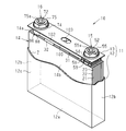
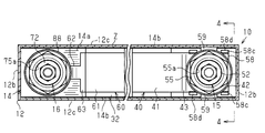
- the disassembled perspective view of the secondary battery of 1st Embodiment The perspective view of the secondary battery of 1st Embodiment. 1 is a cross-sectional plan view showing a secondary battery according to a first embodiment.
- FIG. 4 is a cross-sectional view taken along line 4-4 of FIG.
- the perspective view which shows the secondary battery of 2nd Embodiment.
- the fragmentary longitudinal cross-section which shows the secondary battery of 2nd Embodiment.
- the fragmentary longitudinal cross-section which shows the secondary battery of another example.
- the secondary battery 10 as a power storage device includes a rectangular parallelepiped case 11.
- the case 11 includes a rectangular parallelepiped case main body 12 having an opening, and a rectangular flat lid 13 that closes the opening of the case main body 12.
- the case body 12 and the lid 13 are joined by welding or the like.
- the case body 12 includes a rectangular bottom plate 12a, short side walls 12b extending from a pair of short side edges of the bottom plate 12a, and long side walls 12c extending from a pair of long side edges of the bottom plate 12a.
- the inner surface of the case body 12 is covered with an insulating film Z.
- the secondary battery 10 includes an electrode assembly 14 and an electrolytic solution (not shown) housed in a case 11, and electrode terminals that exchange power with the electrode assembly 14.
- a positive terminal 15 and a negative terminal 16 are provided.
- the positive electrode terminal 15 and the negative electrode terminal 16 are fastened to the lid 13 while penetrating the lid 13 of the case 11.
- the positive electrode terminal 15 and the negative electrode terminal 16 are arranged so as to extend from the inside to the outside of the case 11, and part of the positive electrode terminal 15 and the negative electrode terminal 16 is exposed from the case 11 to the outside.
- the lid 13 corresponds to the wall portion of the case 11 to which the positive terminal 15 and the negative terminal 16 are fixed.
- the secondary battery 10 of the present embodiment is, for example, a lithium ion battery.
- the electrode assembly 14 includes a plurality of positive electrodes 21 and a plurality of negative electrodes 22 as electrodes, and a plurality of separators 23, and the positive electrodes 21 and the negative electrodes 22 are alternately stacked via the separators 23. .
- the positive electrode 21, the negative electrode 22, and the separator 23 are rectangular sheets.
- Each positive electrode 21 has a positive electrode metal foil (for example, aluminum foil) and a positive electrode active material applied on both surfaces thereof.
- Each negative electrode 22 has a negative electrode metal foil (for example, copper foil) and a negative electrode active material applied on both surfaces thereof.
- the separator 23 is a porous film that can transmit ions related to electrical conduction.
- Each positive electrode 21 includes a positive electrode tab 31 protruding from the end of the positive electrode metal foil.
- Each negative electrode 22 includes a negative electrode tab 32 protruding from the end of the negative electrode metal foil.
- the positive electrode 21 is laminated so that the respective positive electrode tabs 31 are arranged in a line along the lamination direction of the electrodes 21 and 22.
- the negative electrode 22 is laminated so that the respective negative electrode tabs 32 are arranged in a row along the lamination direction of the electrodes 21 and 22 so as not to overlap the positive electrode tab 31.
- the direction in which the positive electrode 21, the separator 23, and the negative electrode 22 are stacked is defined as a stacking direction.
- the electrode assembly 14 includes flat surfaces 14b at both ends in the stacking direction. Each flat surface 14 b faces the inner surface of the long side wall 12 c of the case body 12. Therefore, in the present embodiment, the long side wall 12c constitutes a case side wall that faces both end surfaces (the flat surfaces 14b) of the electrode assembly 14 in the stacking direction.
- the length of the straight line connecting the flat surfaces 14 b with the shortest distance along the stacking direction is defined as the thickness N of the electrode assembly 14. That is, the thickness N of the electrode assembly 14 is a dimension along the stacking direction.
- the thickness N of the electrode assembly 14 is shorter than the inner dimension of the case body 12.
- the inner dimension of the case body 12 is the length of a straight line that connects the insulating films Z covering the inner surfaces of the opposed long side walls 12c with the shortest distance.
- the group of negative electrode tabs 32 is stacked in the stacking direction, and is folded toward one end of the electrode assembly 14 in the stacking direction in the stacked state, and then the other end of the electrode assembly 14. It is folded back.
- the group of the positive electrode tabs 31 is overlapped in the stacking direction, and is folded toward one end of the electrode assembly 14 in the stacking direction in the stacked state, and then folded toward the other end of the electrode assembly 14. Yes.
- the positive electrode tab 31 and the negative electrode tab 32 are folded back in the same direction.
- the electrode assembly 14 is accommodated in the case 11 in a state where the end surface 14a where the tabs 31 and 32 exist and the inner surface 13a of the lid 13 where the positive electrode terminal 15 and the negative electrode terminal 16 exist face each other.
- the secondary battery 10 includes a positive electrode conductive member 40 that is used to electrically connect the group of positive electrode tabs 31 to the positive electrode terminal 15.
- the positive electrode conductive member 40 is disposed between the lid 13 of the case 11 and the end surface 14 a of the electrode assembly 14, and is bonded to both the group of positive electrode tabs 31 and the positive electrode terminal 15.
- the positive electrode conductive member 40 is composed of a single metal plate, for example, an aluminum plate.
- the positive electrode conductive member 40 includes a positive electrode tab bonding portion 41 bonded to the group of positive electrode tabs 31 and a terminal bonding portion 42 bonded to the positive electrode terminal 15. Further, the positive electrode conductive member 40 has a positive electrode curved portion 43 that is continuous with both the positive electrode tab joint portion 41 and the terminal joint portion 42 and is curved (bent) in a crank shape.
- the positive terminal 15 has a prismatic terminal head 51, a cylindrical terminal that protrudes from the terminal head 51 toward the lid 13 and has a screw groove 52 a on the outer peripheral surface.
- a shaft portion 52 is provided. That is, the positive electrode terminal 15 has a screw groove 52 a in a portion disposed outside the case 11. The terminal shaft portion 52 protrudes outside the case 11 through the through hole 13 b of the lid 13.
- the terminal head 51 exists in the case 11 and protrudes from the inner surface 13 a of the lid 13 toward the electrode assembly 14.
- the terminal head 51 has an outer diameter larger than the inner diameter of the through hole 13b.
- a seal ring 53 is interposed between the opposing surfaces of the terminal head 51 and the lid 13 in the axial direction of the terminal shaft 52.
- a terminal shaft portion 52 is inserted through the seal ring 53.
- a flanged ring 54 is inserted into the terminal shaft portion 52.
- the flanged ring 54 is fitted in the through hole 13b.
- a nut 55 is screwed into the screw groove 52 a of the terminal shaft portion 52 from the outside of the lid 13.
- a flange of a flanged ring 54 is interposed between the nut 55 and the lid 13.
- the secondary battery 10 includes a first terminal insulating cover 57 on the positive electrode side that covers a part of the terminal head 51, a terminal bonding portion 42, and an end surface 14 a of the electrode assembly 14. And a second terminal insulating cover 58 on the positive electrode interposed therebetween.
- the first terminal insulating cover 57 is insulative and covers the end surface of the terminal head 51 that faces the lid 13 and the outer peripheral surface of the terminal head 51.
- the first terminal insulating cover 57 regulates contact between the end surface of the terminal head 51 and the inner surface 13 a of the lid 13 and insulates the positive terminal 15 from the lid 13 of the case 11.
- the second terminal insulating cover 58 has insulating properties, restricts contact between the terminal joint portion 42 and the end surface 14a of the electrode assembly 14, and insulates the positive electrode terminal 15 from the electrode assembly 14.
- the second terminal insulating cover 58 is made of resin.
- the secondary battery 10 includes a negative electrode conductive member 60 that is used to electrically connect a group of negative electrode tabs 32 to the negative electrode terminal 16.
- the negative electrode conductive member 60 is disposed between the lid 13 of the case 11 and the electrode assembly 14, and is bonded to both the group of negative electrode tabs 32 and the negative electrode terminal 16.
- the negative electrode conductive member 60 is composed of a single metal plate, for example, a copper plate.
- the negative electrode conductive member 60 has a negative electrode tab joint portion 61 joined to the group of negative electrode tabs 32 and a cut-off joint portion 62 joined to the current cut-off portion 80.
- the negative electrode conductive member 60 has a negative electrode curved portion 63 that is continuous with both the negative electrode tab joint portion 61 and the blocking joint portion 62 and is curved (bent) in a crank shape.
- the negative electrode terminal 16 includes a cylindrical terminal head portion 71 and a cylindrical terminal shaft portion 72 protruding from the terminal head portion 71 toward the lid 13 and having a thread groove 72a on the outer peripheral surface.
- the terminal shaft portion 72 protrudes outside the case 11 through the through hole 13 b of the lid 13.
- the terminal head 71 exists in the case 11 and extends from the inner surface 13 a of the lid 13 toward the electrode assembly 14.
- the terminal head 71 has an outer diameter larger than the inner diameter of the through hole 13b.
- a seal ring 73 is interposed between the opposing surfaces of the terminal head 71 and the lid 13 in the axial direction of the terminal shaft 72.
- a terminal shaft 72 is inserted through the seal ring 73.
- a flanged ring 74 is inserted into the terminal shaft portion 72.
- the flanged ring 74 is fitted in the through hole 13b.
- a nut 75 is screwed into the screw groove 72 a of the terminal shaft portion 72 from the outside of the lid 13.
- a flange of a flanged ring 74 is interposed between the nut 75 and the lid 13.
- the secondary battery 10 includes a current interrupting unit 80.
- the current interrupting unit 80 is integrated on the surface of the terminal head 71 close to the electrode assembly 14.
- the current interrupting unit 80 electrically connects the negative electrode terminal 16 to the negative electrode conductive member 60, and electrically connects the negative electrode terminal 16 and the negative electrode conductive member 60 when the pressure in the case 11 exceeds the set pressure. It is configured to block. That is, when the pressure in the case 11 is equal to or lower than the set pressure, the current interrupting unit 80 constitutes part of the energization path between the negative electrode terminal 16 and the negative electrode tab 32, while the pressure in the case 11 exceeds the set pressure. In such a case, the energization path is cut off.
- the current interruption unit 80 includes a deformation plate (not shown) that is deformed by the pressure in the case 11.
- the deformation plate is a diaphragm made of an elastic material, for example, a metal plate, and is disposed at a position closer to the electrode assembly 14 than the negative electrode conductive member 60.
- the deformable plate is deformed by the same pressure and interrupts the energization path in the negative electrode.
- the secondary battery 10 includes a terminal insulating cover 87 on the negative electrode side having insulation and covering an end surface of the terminal head 71 and an outer peripheral surface of the terminal head 71 in the negative electrode terminal 16, and a terminal head.
- a caulking member 88 that unitizes the unit 71 and the current interrupting unit 80.
- the terminal insulating cover 87 is attached to the terminal head 71 from the lid 13 side, restricts the contact of the lid 13 to the terminal head 71, and insulates the lid 13 of the case 11 from the negative terminal 16.
- the secondary battery 10 includes a conductive member cover 100 that is disposed between the positive electrode tab joint portion 41 and the lid 13 and that is disposed between the negative electrode tab joint portion 61 and the lid 13.
- the conductive member cover 100 straddles the positive electrode tab joint portion 41 and the negative electrode tab joint portion 61.
- the conductive member cover 100 is made of resin.
- the conductive member cover 100 includes a rectangular plate-shaped main body 101 and a protrusion 102 extending from the long side edge of the main body 101 toward the electrode assembly 14.
- the lid 13 includes a pressure release valve 103 that is opened when the pressure in the case 11 exceeds the open pressure at the center thereof, and the lid 13 has a portion facing the pressure release valve 103 in the main body 101 of the conductive member cover 100.
- a communication hole 101a exists.
- the pressure release valve 103 and the communication hole 101 a are disposed between the positive electrode tab joint portion 41 and the negative electrode tab joint portion 61 when the electrode assembly 14 is viewed from the lid 13.
- the second terminal insulating cover 58 that is a constituent member of the secondary battery 10 can withstand an impact applied in the stacking direction from the outside of the case 11 (or configured to receive the impact). Is configured.
- the second terminal insulating cover 58 has a rectangular plate shape as a whole.
- the second terminal insulating cover 58 is attached to the positive electrode terminal 15 (specifically, a portion disposed in the case 11) with the longitudinal direction thereof being along the stacking direction. Therefore, the short side direction of the second terminal insulating cover 58 is orthogonal to the stacking direction and extends in the direction along the flat plane 14b.
- the second terminal insulating cover 58 has a circular hole 58b into which a part of the terminal head 51 enters.
- the second terminal insulating cover 58 includes four arm portions 58c.
- the arm portions 58c are provided in pairs on both sides in the short direction of the second terminal insulating cover 58, and extend along the longitudinal direction from the peripheral edge of the hole 58b.
- the second terminal insulating cover 58 has a locking claw 58d at the tip of each arm portion 58c.
- Each locking claw 58d extends toward the positive electrode conductive member 40 from the tip of the arm portion 58c.
- the interval between the locking claws 58d facing the longitudinal direction of the second terminal insulating cover 58 is slightly longer than the length of the terminal joint portion 42 along the stacking direction.
- Each locking claw 58 d is locked to a portion of the positive electrode conductive member 40 that protrudes from the outer peripheral surface of the terminal head 51.
- the second terminal insulating cover 58 includes impact-proof projections 59 sandwiched between a pair of arm portions 58c on each of both longitudinal sides thereof.
- Each impact resistant protrusion 59 has a plate shape and extends in the longitudinal direction of the second terminal insulating cover 58 from the periphery of the hole 58b.
- Each impact-resistant projection 59 protrudes from the tip of each arm portion 58 c in the longitudinal direction of the second terminal insulating cover 58.
- the second terminal insulating cover 58 has a required rigidity along its longitudinal direction.
- the rigidity in the longitudinal direction of the second terminal insulating cover 58 is the resin material of the second terminal insulating cover 58, the thickness of the impact resistant protrusion 59, the length of the impact resistant protrusion 59 in the longitudinal direction and the short direction, It can be appropriately adjusted by changing the size or the like of the hole 58b.
- the rigidity in the longitudinal direction of the second terminal insulating cover 58 is higher than the rigidity of the long side wall 12c in the case body 12.
- the rigidity of the long side wall 12c is the rigidity in the direction (stacking direction) orthogonal to the outer surface of the long side wall 12c.
- the length of the straight line connecting the tips of the shock-proof projections 59 with the shortest distance is the length M of the second terminal insulating cover 58.
- the length M of the second terminal insulating cover 58 is larger than the thickness N of the electrode assembly 14.
- the length M of the second terminal insulating cover 58 is the same as the inner dimension of the case body 12. More specifically, the length M of the second terminal insulating cover 58 is such that the case 11 extends in the stacking direction both before the second terminal insulating cover 58 is accommodated in the case 11 and after it is accommodated in the case 11. It is the same as the inside dimension. For this reason, even if the second terminal insulating cover 58 functions as an impact resistant member, the insulating cover 58 can be easily accommodated in the case 11.
- the length M of the second terminal insulating cover 58 is longer than the thickness N of the electrode assembly 14 before the electrode assembly 14 is expanded in the stacking direction by charging. Although not shown, the surface of the second terminal insulating cover 58 facing the electrode assembly 14 is separated from the end surface 14 a of the electrode assembly 14.
- the length M of the second terminal insulating cover 58 and the inner dimension of the case body 12 are the same.
- the length M of the second terminal insulating cover 58 and the inner dimension of the case body 12 are completely the same. Not only that, but also that the length M of the second terminal insulating cover 58 is slightly different from the inner dimension of the case body 12 so as to allow some variation. For example, even if the length M of the second terminal insulating cover 58 is set slightly shorter than the inner dimension of the case body 12 in order to facilitate the insertion of the second terminal insulating cover 58 into the case 11, the second terminal The length M of the insulating cover 58 and the inner dimension of the case body 12 are considered to be the same.
- a point at the position where the short side of the lid 13 is divided into two equal parts is defined as a bisection point P (see FIG. 1), and a straight line connecting the bisection points P of both short sides is defined as a virtual line R.
- the center point of the terminal shaft portion 52 in the positive electrode terminal 15 is located on the virtual line R of the lid 13.
- the bisection point G of the second terminal insulating cover 58 G is located on the imaginary line R of the lid 13. For this reason, the length from the virtual line R to the tip of each impact-resistant projection 59 along the longitudinal direction of the second terminal insulating cover 58 is the same.
- each impact-resistant projection 59 is closer to each long side wall 12 c than each flat surface 14 b of the electrode assembly 14.
- the inner surface of the case body 12 is covered with an insulating film Z, and the tip of each impact-resistant projection 59 is in contact with the insulating film Z covering the corresponding long side wall 12c.
- An impact along the stacking direction may be applied to the long side wall 12c of the secondary battery 10 from the outer surface side.
- the long side wall 12c tends to be deformed toward the inside of the case body 12 along the stacking direction due to the impact.
- the impact-resistant projection 59 of the second terminal insulating cover 58 receives the long side wall 12c while withstanding the impact.
- the deformation of the long side wall 12c toward the inner side of the case main body 12 is suppressed by the tension of the impact resistant protrusion 59, and the impact reaches the flat surface 14b of the electrode assembly 14 through the long side wall 12c. Is suppressed.
- the second terminal insulating cover 58 that insulates the positive electrode terminal 15 from the electrode assembly 14 is disposed in the case 11 as an impact resistant member. Then, the length M of the second terminal insulating cover 58 (the length M at the location of the impact-resistant projection 59) was made longer than the thickness N of the electrode assembly 14. For this reason, even if an impact along the stacking direction is applied to the long side wall 12 c of the case 11, the impact-resistant projection 59 can withstand the impact, and the impact can be suppressed from reaching the electrode assembly 14.
- the electrode assembly 14 a portion where the plurality of positive electrode tabs 31 are overlapped or a portion where the plurality of negative electrode tabs 32 are overlapped is suppressed from being distorted. Moreover, it is possible to suppress the separator 23 from being broken by the impact, and thus it is possible to suppress the positive electrode 21 from being short-circuited to the negative electrode 22 at the location where the separator 23 is broken.
- the second terminal insulating cover 58 is an existing member that is disposed between the positive electrode terminal 15 and the electrode assembly 14 and is provided for restricting contact between the two, and is a constituent member of the secondary battery 10. is there.
- the rigidity of the second terminal insulating cover 58 in the longitudinal direction is made higher than the rigidity of the long side wall 12c. Therefore, even if the long side wall 12c is deformed by an impact, the second terminal insulating cover 58 is not crushed in the longitudinal direction by the impact, and the second terminal insulating cover 58 withstands the impact and protects the electrode assembly 14. can do.
- the second terminal insulating cover 58 is attached to a portion of the positive electrode terminal 15 disposed in the case 11. Therefore, the positive terminal 15 itself can be protected from impact by the second terminal insulating cover 58.
- the second terminal insulating cover 58 is disposed near the positive electrode tab 31 in the electrode assembly 14.
- the portion near the end face 14a of the electrode assembly 14 from which the positive electrode tab 31 protrudes does not have an active material and is vulnerable to impact.
- the presence of the second terminal insulating cover 58 can protect a portion near the end surface 14a of the electrode assembly 14 from an impact, and suppresses a portion near the end surface 14a of the electrode assembly 14 from being distorted by the impact. be able to.
- the second terminal insulating cover 58 does not have the impact-proof projection 59, and the length of the second terminal insulating cover 58 in the longitudinal direction at the arm portion 58c is It is shorter than the thickness N of the electrode assembly 14.
- the nuts 55 and 75 have female screw holes 55a and 75a.
- the maximum length L1 and the minimum length L2 of the nuts 55 and 75 which are dimensions along the radial direction of the female screw holes 55a and 75a, are a caulking member 88 that covers the thickness N of the electrode assembly 14 and the current interrupting portion 80. Greater than the outer diameter of
- the maximum length L1 of the nuts 55 and 75 is a length of a straight line connecting corners facing each other in the radial direction in each of the hexagonal nuts 55 and 75 in a plan view.
- the minimum length L2 of the nuts 55 and 75 is a length of a straight line connecting outer surfaces facing each other in the radial direction in each of the hexagonal nuts 55 and 75 in a plan view.
- the maximum length L1 is longer than the minimum length L2.
- the nuts 55 and 75 are made of metal and have a thickness in the radial direction, the rigidity is higher than that of the long side wall 12c.
- the outer surfaces of the nuts 55 and 75 are flush with the outer surface of the long side wall 12c in the case 11, and the nuts 55 and 75 are straight lines connecting the outer surfaces facing each other in the radial direction.
- the nuts 55 and 75 are arranged in the secondary battery 10 so that the minimum length L2 of the nuts 55 and 75 is larger than the thickness N of the electrode assembly 14.
- the nuts 55 and 75 that are constituent members of the secondary battery 10 function as an impact resistant member.
- the nuts 55 and 75 can withstand the impact, and the impact is applied to the case 11, and thus the electrode assembly. It can suppress reaching to the solid 14.
- the electrode assembly 14 a portion where the plurality of positive electrode tabs 31 are overlapped or a portion where the plurality of negative electrode tabs 32 are overlapped is suppressed from being distorted.
- the nuts 55 and 75 are members for fixing the positive electrode terminal 15 and the negative electrode terminal 16 to the lid 13, and the nuts 55 and 75 are constituent members of the secondary battery 10.
- the nuts 55 and 75 are made of metal, have excellent impact resistance, and are disposed outside the case 11. For this reason, the nuts 55 and 75 can first receive an impact from the outside of the case 11, and can suitably suppress the impact on the electrode assembly 14 and the current interrupting portion 80.
- the length K along the short side of the main body 101 in the conductive member cover 100 may be larger than the thickness N of the electrode assembly 14.
- Each protrusion 102 of the conductive member cover 100 has a side wall surface 102a facing the inner surface of the long side wall 12c.
- the length K along the short side of the main body 101 is a length of a straight line that connects the side wall surfaces 102a of the protrusions 102 with the shortest distance.
- the conductive member cover 100 which is a constituent member of the secondary battery 10 and is provided in the case 11 functions as an impact resistant member.
- the length K which is the dimension of the conductive member cover 100 along the stacking direction, is the case 11 (case body 12) both before and after the conductive member cover 100 is received in the case 11. It is less than the inner dimension. For this reason, even if it is a case where the conductive member cover 100 functions as an impact-resistant member, it is easy to accommodate the conductive member cover 100 in the case main body 12.
- each protrusion 102 in the conductive member cover 100 is separated from the end surface 14 a of the electrode assembly 14.
- the conductive member cover 100 has a required rigidity in the direction in which the short side extends.
- the rigidity in the extending direction of the short side of the conductive member cover 100 changes the resin material of the conductive member cover 100, the thickness of the conductive member cover 100, the length of the long side and the short side of the conductive member cover 100 in the extending direction, and the like. It can be adjusted as appropriate.
- the rigidity in the direction along the short side of the conductive member cover 100 is higher than the rigidity of the long side wall 12 c in the case body 12.
- the conductive member cover 100 When configured in this manner, even if an impact is applied to the long side wall 12c of the case 11 from the outer surface side, the conductive member cover 100 can withstand the impact, and the impact is prevented from reaching the case 11 and thus the electrode assembly 14. it can. In addition, the conductive member cover 100 is separated from the end surface 14 a of the electrode assembly 14. For this reason, even if an impact is transmitted to the conductive member cover 100, it is suppressed that the impact is transmitted to the electrode assembly 14.
- the electrode assembly 14 a portion where the plurality of positive electrode tabs 31 are overlapped or a portion where the plurality of negative electrode tabs 32 are overlapped is suppressed from being distorted. Moreover, it is possible to suppress the separator 23 from being broken by an impact, and thus it is possible to prevent the positive electrode 21 from being short-circuited to the negative electrode 22 at the location where the separator 23 is broken.
- the length K along the short side of the main body 101 in the conductive member cover 100 (the dimension along the stacking direction of the conductive member cover 100) K may be the same as the thickness N of the electrode assembly 14.
- the length K along the short side of the main body 101 in the conductive member cover 100 is set larger than the outer diameter of the caulking member 88 of the current interrupting portion 80 to make the conductive member cover 100 the current interrupting portion. You may make it function as an impact-resistant member which protects 80.
- the length K which is a dimension along the stacking direction is the case 11 (case body 12) both before the conductive member cover 100 is accommodated in the case 11 and after it is accommodated in the case 11. ) Or less.
- the front end surface of the protruding portion 102 in the conductive member cover 100 is separated from the end surface 14 a of the electrode assembly 14.
- the maximum length L1 and the minimum length L2 of the nuts 55 and 75 may be larger than the thickness N of the electrode assembly 14. That is, both the length M of the second terminal insulating cover 58 at the location of the impact-proof projection 59 and the maximum length L1 and the minimum length L2 of the nuts 55 and 75 are determined by the thickness N of the electrode assembly 14. It may be larger.
- the length K along the short side of the main body 101 in the conductive member cover 100 may be larger than the thickness N of the electrode assembly 14.
- the length M of the second terminal insulating cover 58 may be set longer than the thickness N of the electrode assembly 14 in a state where the electrode assembly 14 is expanded in the stacking direction by charging.
- the impact resistance is also obtained when the secondary battery 10 is manufactured and an impact is applied to the long side wall 12c of the case 11 before the initial charging.
- the projection 59 can withstand an impact, and the impact can be suppressed from reaching the electrode assembly 14.
- the current interrupting unit 80 may be omitted in the first embodiment.
- the first terminal insulating cover 57 and the second terminal insulating cover 58 are attached to the negative electrode terminal 16, and the first terminal insulating cover 57 and the second terminal insulating cover 58 are used as impact resistant members.
- the dimension along the stacking direction is set to be equal to or larger than the thickness N of the electrode assembly 14, and before the insulating covers 57 and 58 are accommodated in the case 11.
- the inner dimension of the case 11 (the case main body 12) may be equal to or less.
- the first terminal insulating cover 57 that is a constituent member of the secondary battery 10 functions as an impact-resistant member.
- the dimension along the stacking direction of the electrode assembly 14 may be equal to or greater than the thickness N of the electrode assembly 14.
- the dimension of the first terminal insulating cover 57 along the stacking direction is the case 11 (case case) before and after the first terminal insulating cover 57 is stored in the case 11. It is less than the inner dimension of the main body 12).
- one of the maximum length L1 and the minimum length L2 of the nuts 55 and 75 may be the same as the thickness N of the electrode assembly 14.
- the second terminal insulating cover 58 for insulating the positive electrode terminal 15 from the electrode assembly 14 is used as the impact resistant member. 11 may be arranged.
- the length M which is a dimension along the stacking direction, is both before the second terminal insulating cover 58 is accommodated in the case 11 and after it is accommodated in the case 11. It is below the inner dimension of case 11 (case main body 12). Further, the surface of the second terminal insulating cover 58 facing the electrode assembly 14 is separated from the end surface 14 a of the electrode assembly 14.
- the length M of the impact-resistant projection 59 in the second terminal insulating cover 58 may be the same as the thickness N of the electrode assembly 14.
- the electrode assembly 14 is not limited to the laminated type, but may be a wound type in which a belt-like positive electrode and a belt-like negative electrode are wound and laminated in layers. In the case of a wound electrode assembly, the direction in which the flat surfaces overlap is the stacking direction of the electrode assemblies.
- the electrode assembly 14 is a type in which the dimension (thickness N) in the stacking direction changes due to charging / discharging, but it may be a type in which the dimension in the stacking direction does not change due to charging / discharging. Good. Even in a secondary battery using an electrode assembly whose dimensions in the stacking direction do not change due to charge / discharge, the length M of the second terminal insulating cover 58 and the length K of the conductive member cover 100 are the same as the case 11. The inside dimension of the case 11 (case body 12) is less than or equal to both before and after being accommodated in the case 11.
- the secondary battery 10 is a lithium ion secondary battery, but is not limited thereto, and may be another secondary battery. In short, any secondary battery that transfers ions while transferring ions between the positive electrode active material and the negative electrode active material may be used. Each of the above embodiments may be applied to a capacitor as a power storage device.
- the case 11 of the secondary battery 10 does not have to be a square cylinder with the bottom plate 12a being rectangular, and the case 11 may be a square cylinder with the bottom plate being square.
Landscapes
- Engineering & Computer Science (AREA)
- Power Engineering (AREA)
- Chemical & Material Sciences (AREA)
- Chemical Kinetics & Catalysis (AREA)
- Electrochemistry (AREA)
- General Chemical & Material Sciences (AREA)
- Microelectronics & Electronic Packaging (AREA)
- Connection Of Batteries Or Terminals (AREA)
- Secondary Cells (AREA)
- Electric Double-Layer Capacitors Or The Like (AREA)
Abstract
蓄電装置は、異なる極性の電極がセパレータを介して交互に積層された電極組立体と、電極組立体が収容されているケースと、を有する。また蓄電装置は、ケースの壁部に固定されている電極端子であって、ケースの内側から外側にまで延びるように配置され、かつ電極組立体と電力の授受を行う電極端子と、電極及びセパレータが積層された方向である積層方向にケースの外側から加わる衝撃を受け止めるように構成された耐衝撃部材と、を有する。積層方向に沿った耐衝撃部材の寸法は、積層方向に沿った電極組立体の寸法以上である。
Description
本発明は、電極組立体と、ケースと、電極端子と、を有する蓄電装置に関する。
EV(Electric Vehicle)やPHV(Plug in Hybrid Vehicle)などの車両には、原動機である電動機への供給電力を蓄える蓄電装置としてリチウムイオン電池などの二次電池が搭載されている。例えば、特許文献1に記載の二次電池は、セパレータを介して交互に積層された正極電極と負極電極とを有する電極組立体と、電極組立体を収容するケースと、を有する。正極電極及び負極電極は活物質層を有している。電極組立体は、電極及びセパレータの積層方向(以下、単に「積層方向」という。)における電極組立体の両端に長方形状の偏平面を有する。
電極組立体の偏平面に対向した二次電池の壁部に対し、その外面側から、積層方向に沿った衝撃が加わる場合がある。この場合、衝撃によってケースが潰れるとともに、電極組立体にも積層方向に沿った衝撃が加わり、電極組立体が損傷等を受けてしまう。
本発明の目的は、積層方向に沿った衝撃から電極組立体を保護することができる蓄電装置を提供することにある。
上記問題点を解決するための蓄電装置は、異なる極性の電極がセパレータを介して交互に積層された電極組立体と、前記電極組立体が収容されているケースと、前記ケースの壁部に固定されている電極端子であって、前記ケースの内側から外側にまで延びるように配置され、かつ前記電極組立体と電力の授受を行う前記電極端子と、前記電極及び前記セパレータが積層された方向である積層方向に前記ケースの外側から加わる衝撃を受け止めるように構成された耐衝撃部材と、を有し、前記積層方向に沿った前記耐衝撃部材の寸法が、前記積層方向に沿った前記電極組立体の寸法以上である。
これによれば、蓄電装置に対し、電極組立体の積層方向に沿ってケースの外から衝撃が加わった場合、衝撃がケースから電極組立体に加わる前に耐衝撃部材に加わる。そして、耐衝撃部材が衝撃に耐えることで、電極組立体に衝撃荷重が及ぶことを抑制し、電極組立体を衝撃から保護することができる。
上記問題点を解決するための蓄電装置は、異なる極性の電極がセパレータを介して交互に積層された電極組立体と、前記電極組立体が収容されているケースと、前記ケースの壁部に固定されている電極端子であって、前記ケースの内側から外側にまで延びるように配置され、かつ前記電極組立体と電力の授受を行う前記電極端子と、一方の極性を有する前記電極端子と前記電極組立体との間の通電経路上に設けられ、前記ケースの内部圧力が設定圧力を超えたときに前記通電経路を流れる電流を遮断するように構成される電流遮断部と、前記電極及び前記セパレータが積層された方向である積層方向に前記ケースの外側から加わる衝撃を受け止めるように構成された耐衝撃部材と、を有し、前記積層方向に沿った前記耐衝撃部材の寸法が、前記積層方向に沿った前記電流遮断部の寸法以上である。
これによれば、蓄電装置に対し、電極組立体の積層方向に沿ってケースの外から衝撃が加わった場合、衝撃がケースから電極組立体及び電流遮断部に加わる前に耐衝撃部材に加わる。そして、耐衝撃部材が衝撃に耐えることで、電極組立体及び電流遮断部に衝撃荷重が及ぶことを抑制し、電極組立体及び電流遮断部を衝撃から保護することができる。
電流遮断部として、例えば、ケースの内圧が所定の圧力に達すると変形して通電経路を流れる電流を遮断する変形板を備えたものがある。このような電流遮断部において、ケースの内圧を受けて変形板を変形可能とするためには、変形板に高い剛性を持たせることができず、電流遮断部に耐衝撃性を持たせるのは困難である。そのため、耐衝撃部材によって衝撃を受け止めることが可能なように蓄電装置を構成すれば、電流遮断部に耐衝撃性を持たせることなく、電流遮断部を保護することができる。
また、蓄電装置について、前記耐衝撃部材は前記ケース内に収容されるように構成され、前記積層方向に沿った前記耐衝撃部材の寸法は、前記耐衝撃部材が前記ケースに収容される前と前記ケースに収容された後との双方において、前記積層方向に沿った前記ケースの内寸以下である。
これによれば、耐衝撃部材の寸法がケースの内寸以下であるため、耐衝撃部材をケース内に収容しやすい。
また、蓄電装置について、前記電極組立体は、前記壁部の内面に対向する端面を備え、前記耐衝撃部材は、前記電極組立体の前記端面から離隔するように前記ケース内に配置されている。
また、蓄電装置について、前記電極組立体は、前記壁部の内面に対向する端面を備え、前記耐衝撃部材は、前記電極組立体の前記端面から離隔するように前記ケース内に配置されている。
これによれば、蓄電装置に対し、電極組立体の積層方向に沿ってケースの外から衝撃が加わった場合、衝撃が耐衝撃部材に加わる。このとき、耐衝撃部材が電極組立体の端面から隔離しているため、衝撃が、耐衝撃部材を介して電極組立体に伝わることを抑制できる。
また、蓄電装置について、前記耐衝撃部材は、前記電極端子における前記ケース内に配置される部分に装着される端子絶縁カバーであり、該端子絶縁カバーは前記電極端子を前記電極組立体又は前記ケースから絶縁する。
これによれば、ケース内において、端子絶縁カバーは電極端子に装着されることから、端子絶縁カバーによって、電極端子も衝撃から保護することができる。また、電極組立体において、電極端子に近い部位には、電極組立体の端面から突出したタブが配置される場合が多い。タブは電極の枚数だけ重ねられた構成であり、衝撃によって歪みやすい。しかし、端子絶縁カバーを耐衝撃部材とすることで、電極組立体におけるタブ付近が衝撃によって歪むことを抑制することができる。
また、蓄電装置について、前記電極端子は、前記ケース外に配置される部分にネジ溝を有し、前記耐衝撃部材は、前記電極端子を前記ケースの壁部に固定するために前記ネジ溝に螺合されるナットであってもよい。
これによれば、ナットは、金属材料によって形成され、耐衝撃性に優れる。よって、ナットによって、ケースの外側からの衝撃を好適に受け止めることができる。
また、蓄電装置について、前記蓄電装置は、異なる極性の導電部材を前記ケース内に備え、前記各導電部材は各極性の前記電極を該電極と同じ極性の前記電極端子に電気的に接続し、前記各導電部材は、前記電極端子の固定された前記壁部と前記電極組立体との間に配設されており、前記耐衝撃部材は、異なる極性の前記導電部材同士に跨るように設けられて前記導電部材と前記壁部との接触を規制する導電部材カバーであってもよい。
また、蓄電装置について、前記蓄電装置は、異なる極性の導電部材を前記ケース内に備え、前記各導電部材は各極性の前記電極を該電極と同じ極性の前記電極端子に電気的に接続し、前記各導電部材は、前記電極端子の固定された前記壁部と前記電極組立体との間に配設されており、前記耐衝撃部材は、異なる極性の前記導電部材同士に跨るように設けられて前記導電部材と前記壁部との接触を規制する導電部材カバーであってもよい。
これによれば、導電部材カバーは、導電部材に装着されることから、導電部材カバーによって、導電部材も衝撃から保護することができる。また、導電部材は、電極組立体の端面から突出したタブに接合される場合が多い。タブは電極の枚数だけ重ねられた構成であり、衝撃荷重によって歪みやすい。しかし、導電部材カバーを耐衝撃部材とすることで、電極組立体においてタブ付近が歪むことを抑制することができる。
また、蓄電装置について、前記ケースは、前記電極組立体における前記積層方向の両端面に対向するケース側壁を備え、前記耐衝撃部材の剛性は、前記ケース側壁の剛性より高い方が好ましい。
これによれば、ケース側壁が衝撃荷重によって変形しても、耐衝撃部材が衝撃に耐えながら衝撃を受け止め、電極組立体に衝撃が及ぶことを抑制することができる。
前記蓄電装置は二次電池である。
前記蓄電装置は二次電池である。
本発明によれば、積層方向に沿った衝撃から電極組立体を保護することができる。
(第1の実施形態)
以下、二次電池10の第1の実施形態を図1~図4にしたがって説明する。
図2に示すように、蓄電装置としての二次電池10は、直方体形状のケース11を備えている。ケース11は、開口部を有する直方体状のケース本体12と、ケース本体12の開口部を塞ぐ長方形平板状の蓋13とを備えている。ケース本体12と蓋13とは、溶接などによって接合されている。ケース本体12は、矩形状の底板12aと、底板12aの一対の短側縁から延びる短側壁12bと、底板12aの一対の長側縁から延びる長側壁12cと、を備える。ケース本体12の内面は、絶縁フィルムZによって覆われている。
以下、二次電池10の第1の実施形態を図1~図4にしたがって説明する。
図2に示すように、蓄電装置としての二次電池10は、直方体形状のケース11を備えている。ケース11は、開口部を有する直方体状のケース本体12と、ケース本体12の開口部を塞ぐ長方形平板状の蓋13とを備えている。ケース本体12と蓋13とは、溶接などによって接合されている。ケース本体12は、矩形状の底板12aと、底板12aの一対の短側縁から延びる短側壁12bと、底板12aの一対の長側縁から延びる長側壁12cと、を備える。ケース本体12の内面は、絶縁フィルムZによって覆われている。
図1及び図2に示すように、二次電池10は、ケース11に収容されている電極組立体14及び電解液(図示略)と、電極組立体14と電力の授受を行う電極端子としての正極端子15及び負極端子16とを備えている。正極端子15及び負極端子16は、ケース11の蓋13を貫通した状態で蓋13に締結されている。正極端子15及び負極端子16は、ケース11の内側から外側にまで延びるように配置され、正極端子15及び負極端子16の一部は、ケース11から外部に露出している。本実施形態では、蓋13が、正極端子15及び負極端子16が固定された、ケース11の壁部に対応する。本実施形態の二次電池10は、例えばリチウムイオン電池である。
電極組立体14は、電極としての複数の正極電極21及び複数の負極電極22と、複数のセパレータ23とを有し、正極電極21及び負極電極22は、セパレータ23を介して交互に積層される。正極電極21、負極電極22及びセパレータ23は、長方形状のシートである。
各正極電極21は、正極金属箔(例えばアルミニウム箔)と、その両面に塗布される正極活物質とを有する。各負極電極22は、負極金属箔(例えば銅箔)と、その両面に塗布される負極活物質とを有する。セパレータ23は、電気伝導に係るイオンが透過可能な多孔質膜である。
各正極電極21は、正極金属箔の端部から突出した正極タブ31を備える。また、各負極電極22は、負極金属箔の端部から突出した負極タブ32を備える。正極電極21は、それぞれの正極タブ31が電極21,22の積層方向に沿って列状に配置されるように積層されている。同様に、負極電極22は、それぞれの負極タブ32が、正極タブ31と重ならないように電極21,22の積層方向に沿って列状に配置されるように積層されている。
図4に示すように、本実施形態において、正極電極21と、セパレータ23と、負極電極22とを積層した方向を、積層方向とする。電極組立体14は、積層方向の両端に偏平面14bを備える。各偏平面14bは、ケース本体12の長側壁12cの内面に対向している。よって、本実施形態では、長側壁12cが、電極組立体14における積層方向の両端面(偏平面14b)に対向するケース側壁を構成する。
電極組立体14において、積層方向に沿って偏平面14b同士を最短距離で結ぶ直線の長さを、電極組立体14の厚みNとする。すなわち、電極組立体14の厚みNは、積層方向に沿う寸法である。この電極組立体14の厚みNは、ケース本体12の内寸より短い。ケース本体12の内寸とは、対向した長側壁12cの内面を覆う絶縁フィルムZ同士を最短距離で結ぶ直線の長さである。
図1に示すように、負極タブ32の群は、積層方向に重ねられ、その重ねられた状態で積層方向における電極組立体14の一端に向けて折り曲げられてから電極組立体14の他端に向けて折り返されている。同様に正極タブ31の群は、積層方向に重ねられ、その重ねられた状態で積層方向における電極組立体14の一端に向けて折り曲げられてから電極組立体14の他端に向けて折り返されている。本実施形態では、正極タブ31及び負極タブ32は、同じ方向に折り返されている。そして、電極組立体14は、タブ31,32が存在する端面14aと、正極端子15及び負極端子16が存在する蓋13の内面13aとが対向する状態でケース11内に収容されている。
二次電池10は、正極タブ31の群を正極端子15と電気的に接続するのに用いられる正極導電部材40を備える。正極導電部材40は、ケース11の蓋13と電極組立体14の端面14aとの間に配置され、正極タブ31の群及び正極端子15の双方に接合されている。
正極導電部材40は、一枚の金属板、例えばアルミニウム板で構成されている。正極導電部材40は、正極タブ31の群に接合されている正極タブ接合部41と、正極端子15に接合されている端子接合部42とを有している。さらに、正極導電部材40は、正極タブ接合部41及び端子接合部42の双方と連続し、クランク状に湾曲(屈曲)した正極湾曲部43を有している。
図1及び図4に示すように、正極端子15は、角柱状の端子頭部51と、端子頭部51から蓋13に向けて突出し、かつ、外周面にネジ溝52aを有する筒形状の端子軸部52とを備えている。すなわち、正極端子15はケース11外に配置される部分にネジ溝52aを有する。端子軸部52は、蓋13の貫通孔13bを通ってケース11の外部に突出している。
端子頭部51は、ケース11内に存在し、蓋13の内面13aから電極組立体14に向けて突出している。端子頭部51は、貫通孔13bの内径よりも大きい外径を有している。端子軸部52の軸方向における端子頭部51と蓋13との対向面の間には、シールリング53が介在している。シールリング53には、端子軸部52が挿通されている。
端子軸部52には、フランジ付きリング54が挿通されている。フランジ付きリング54は、貫通孔13bに嵌合している。端子軸部52のネジ溝52aには、蓋13の外側からナット55が螺合されている。ナット55と蓋13との間には、フランジ付きリング54のフランジが介在している。
図1及び図4に示すように、二次電池10は、端子頭部51の一部を覆う正極側の第1端子絶縁カバー57と、端子接合部42と電極組立体14の端面14aとの間に介在する正極側の第2端子絶縁カバー58とを備える。第1端子絶縁カバー57は、絶縁性を有しており、端子頭部51における蓋13を向く端面、及び端子頭部51の外周面を覆う。第1端子絶縁カバー57は、端子頭部51の上記端面と蓋13の内面13aとの接触を規制し、正極端子15をケース11の蓋13から絶縁する。
第2端子絶縁カバー58は、絶縁性を有しており、端子接合部42と電極組立体14の端面14aとの接触を規制し、正極端子15を電極組立体14から絶縁する。第2端子絶縁カバー58は、樹脂製である。
図1又は図3に示すように、二次電池10は、負極タブ32の群を負極端子16と電気的に接続するのに用いられる負極導電部材60を備えている。負極導電部材60は、ケース11の蓋13と電極組立体14との間に配置され、負極タブ32の群及び負極端子16の双方に接合されている。
負極導電部材60は、一枚の金属板、例えば銅板で構成されている。負極導電部材60は、負極タブ32の群に接合されている負極タブ接合部61と、電流遮断部80に接合されている遮断接合部62とを有している。さらに、負極導電部材60は、負極タブ接合部61及び遮断接合部62の双方と連続し、クランク状に湾曲(屈曲)した負極湾曲部63を有している。
負極端子16は、円柱状の端子頭部71と、その端子頭部71から蓋13に向けて突出し、かつ外周面にネジ溝72aを有する筒形状の端子軸部72とを備えている。端子軸部72は、蓋13の貫通孔13bを通ってケース11外に突出している。
端子頭部71は、ケース11内に存在し、蓋13の内面13aから電極組立体14に向けて延びている。端子頭部71は、貫通孔13bの内径よりも大きい外径を有している。端子軸部72の軸方向における端子頭部71と蓋13との対向面の間には、シールリング73が介在している。シールリング73には、端子軸部72が挿通されている。
端子軸部72には、フランジ付きリング74が挿通されている。フランジ付きリング74は、貫通孔13bに嵌合している。端子軸部72のネジ溝72aには、蓋13の外側からナット75が螺合されている。ナット75と蓋13との間には、フランジ付きリング74のフランジが介在している。
二次電池10は、電流遮断部80を備える。電流遮断部80は、端子頭部71における電極組立体14に近い面に一体化されている。電流遮断部80は、負極端子16を負極導電部材60と電気的に接続し、ケース11内の圧力が設定圧力を超えた場合に、負極端子16と負極導電部材60との電気的な接続を遮断するように構成されている。つまり、電流遮断部80は、ケース11内の圧力が設定圧力以下である場合において負極端子16及び負極タブ32間の通電経路の一部を構成する一方、ケース11内の圧力が設定圧力を超えた場合において上記通電経路を遮断するように構成されている。
電流遮断部80は、ケース11内の圧力によって変形する変形板(図示せず)を備えている。変形板は、弾性材料、例えば金属板で構成されたダイヤフラムであり、負極導電部材60よりも電極組立体14に近い位置に配置されている。変形板は、ケース11内に設定圧力よりも大きい圧力が付与された場合には、同圧力によって変形して、負極における通電経路を遮断する。
図1に示すように、二次電池10は、負極端子16における端子頭部71の端面及び端子頭部71の外周面を覆う、絶縁性を有した負極側の端子絶縁カバー87と、端子頭部71及び電流遮断部80をユニット化するカシメ部材88とを備える。端子絶縁カバー87は、端子頭部71に対して蓋13側から取り付けられており、蓋13の端子頭部71への接触を規制し、ケース11の蓋13を負極端子16から絶縁する。
二次電池10は、正極タブ接合部41と蓋13との間に配置されるとともに負極タブ接合部61と蓋13との間に配置される導電部材カバー100を備えている。導電部材カバー100は、正極タブ接合部41と負極タブ接合部61とに跨る。導電部材カバー100は、樹脂製である。導電部材カバー100は、長方形の板状の本体部101と、この本体部101の長側縁から電極組立体14に向けて延びる突出部102とを有している。
蓋13は、その中央部にケース11内の圧力が開放圧を超えた場合に開放される圧力開放弁103を備え、導電部材カバー100の本体部101における圧力開放弁103と対向する部位には連通孔101aが存在する。圧力開放弁103及び連通孔101aは、蓋13から電極組立体14を見たときに、正極タブ接合部41と負極タブ接合部61との間に配置されている。
次に、第2端子絶縁カバー58について詳細に説明する。本実施形態では、二次電池10の構成部材である第2端子絶縁カバー58が、ケース11の外側から積層方向に加わる衝撃に耐え得る(あるいは、衝撃を受け止めるように構成された)耐衝撃部材を構成している。
第2端子絶縁カバー58は、全体として矩形板状である。そして、第2端子絶縁カバー58は、その長手方向が積層方向に沿う状態で正極端子15(詳細には、ケース11内に配置される部分)に装着されている。よって、第2端子絶縁カバー58の短手方向は、積層方向に直交し、偏平面14bに沿う方向に延びている。
第2端子絶縁カバー58は、端子頭部51の一部が入り込む円形状の孔58bを有する。また、第2端子絶縁カバー58は4つの腕部58cを備える。腕部58cは、第2端子絶縁カバー58の短手方向両側に一対ずつ設けられ、孔58bの周縁から長手方向に沿って延びる。また、第2端子絶縁カバー58は、各腕部58cの先端に係止爪58dを有する。各係止爪58dは、腕部58cの先端から正極導電部材40に向けて延びている。第2端子絶縁カバー58の長手方向に対向した係止爪58dの間隔は、積層方向に沿った端子接合部42の長さより若干長い。そして、各係止爪58dは、正極導電部材40における端子頭部51の外周面からはみ出した部分に係止している。
第2端子絶縁カバー58は、その長手方向両側の各々において、一対の腕部58cに挟まれた耐衝撃用突部59を備える。各耐衝撃用突部59は板状をなしており、孔58bの周縁から第2端子絶縁カバー58の長手方向に延びている。各耐衝撃用突部59は、第2端子絶縁カバー58の長手方向において、各腕部58cの先端より飛び出している。第2端子絶縁カバー58は、その長手方向に沿って所要の剛性を有している。第2端子絶縁カバー58の長手方向における剛性は、第2端子絶縁カバー58の樹脂材料、耐衝撃用突部59の厚み、耐衝撃用突部59の長手方向及び短手方向への長さ、孔58bの大きさ等を変更することで適宜調整可能である。
そして、第2端子絶縁カバー58の長手方向における剛性は、ケース本体12における長側壁12cの剛性より高い。長側壁12cの剛性とは、長側壁12cの外面に直交する方向(積層方向)に対しての剛性である。
図4に示すように、第2端子絶縁カバー58の長手方向に沿って、耐衝撃用突部59の先端同士を最短距離で結ぶ直線の長さを、第2端子絶縁カバー58の長さMとする。第2端子絶縁カバー58の長さMは、電極組立体14の厚みNより大きい。また、第2端子絶縁カバー58の長さMは、ケース本体12の内寸と同一である。より詳しくは、第2端子絶縁カバー58の長さMは、第2端子絶縁カバー58がケース11に収容される前とケース11に収容された後との双方において、積層方向に沿ったケース11の内寸と同一である。このため、第2端子絶縁カバー58が耐衝撃部材として機能する場合であっても、該絶縁カバー58をケース11内に収容しやすい。
また、第2端子絶縁カバー58の長さMは、電極組立体14が充電によって積層方向へ膨らむ前の状態において、電極組立体14の厚みNより長い。また、図示しないが、第2端子絶縁カバー58における電極組立体14への対向面は、電極組立体14の端面14aから離隔している。
第2端子絶縁カバー58の長さMと、ケース本体12の内寸とが同一であるとは、第2端子絶縁カバー58の長さMと、ケース本体12の内寸とが完全に同一であることだけでなく、ある程度のバラツキを許容するように、第2端子絶縁カバー58の長さMが、ケース本体12の内寸と若干異なることをも含む。例えば、第2端子絶縁カバー58をケース11内に挿入し易くするために、第2端子絶縁カバー58の長さMがケース本体12の内寸より若干短く設定されている場合も、第2端子絶縁カバー58の長さMと、ケース本体12の内寸とが同一であると見なされる。
ここで、蓋13における短辺を二等分する位置にある点を二等分点P(図1参照)とし、両短辺の二等分点P同士を結ぶ直線を仮想線Rとする。正極端子15における端子軸部52の中心点が、蓋13の仮想線R上に位置している。この正極端子15に取り付けられた第2端子絶縁カバー58における長手方向の長さMを二等分する位置にある点を二等分点Gとすると、第2端子絶縁カバー58の二等分点Gが、蓋13の仮想線R上に位置している。このため、仮想線Rから第2端子絶縁カバー58の長手方向に沿った、各耐衝撃用突部59の先端までの長さは同じである。
各耐衝撃用突部59の先端は、電極組立体14の各偏平面14bよりも各長側壁12cに近付いている。ケース本体12の内面は、絶縁フィルムZによって覆われており、各耐衝撃用突部59の先端は、対応する長側壁12cを覆った絶縁フィルムZに当接している。
次に、二次電池10の作用を記載する。
二次電池10の長側壁12cに対し、その外面側から、積層方向に沿った衝撃が加わる場合がある。この場合、長側壁12cはその衝撃によって、積層方向に沿ってケース本体12の内側に向けて変形しようとする。このとき、第2端子絶縁カバー58の耐衝撃用突部59が、衝撃に耐えながら長側壁12cを受け止める。そして、耐衝撃用突部59の突っ張りにより、ケース本体12の内側に向けた長側壁12cの変形が抑制され、長側壁12cを介して、上記衝撃が電極組立体14の偏平面14bに及ぶことが抑制される。
二次電池10の長側壁12cに対し、その外面側から、積層方向に沿った衝撃が加わる場合がある。この場合、長側壁12cはその衝撃によって、積層方向に沿ってケース本体12の内側に向けて変形しようとする。このとき、第2端子絶縁カバー58の耐衝撃用突部59が、衝撃に耐えながら長側壁12cを受け止める。そして、耐衝撃用突部59の突っ張りにより、ケース本体12の内側に向けた長側壁12cの変形が抑制され、長側壁12cを介して、上記衝撃が電極組立体14の偏平面14bに及ぶことが抑制される。
上記第1の実施形態によれば、以下のような効果を得ることができる。
(1)正極端子15を電極組立体14から絶縁する第2端子絶縁カバー58を耐衝撃部材としてケース11内に配置した。そして、第2端子絶縁カバー58の長さM(耐衝撃用突部59の箇所での長さM)を、電極組立体14の厚みNより長くした。このため、ケース11の長側壁12cに対し積層方向に沿った衝撃が加わっても、耐衝撃用突部59が衝撃に耐えて、この衝撃が電極組立体14に及ぶことを抑制できる。その結果として、電極組立体14において、複数の正極タブ31が重ねられた部位又は複数の負極タブ32が重ねられた部位が歪むことが抑制される。また、上記衝撃によってセパレータ23が破れることが抑制され、これによりセパレータ23の破れた箇所で正極電極21が負極電極22と短絡することも抑制できる。
(1)正極端子15を電極組立体14から絶縁する第2端子絶縁カバー58を耐衝撃部材としてケース11内に配置した。そして、第2端子絶縁カバー58の長さM(耐衝撃用突部59の箇所での長さM)を、電極組立体14の厚みNより長くした。このため、ケース11の長側壁12cに対し積層方向に沿った衝撃が加わっても、耐衝撃用突部59が衝撃に耐えて、この衝撃が電極組立体14に及ぶことを抑制できる。その結果として、電極組立体14において、複数の正極タブ31が重ねられた部位又は複数の負極タブ32が重ねられた部位が歪むことが抑制される。また、上記衝撃によってセパレータ23が破れることが抑制され、これによりセパレータ23の破れた箇所で正極電極21が負極電極22と短絡することも抑制できる。
(2)第2端子絶縁カバー58は、正極端子15と電極組立体14との間に配置されて両者の接触を規制するために設けられる既存の部材であり、二次電池10の構成部材である。この第2端子絶縁カバー58に耐衝撃用突部59を設けることで、衝撃が電極組立体14に及ぶことを抑制できる。したがって、ケース11内に新たに部品を追加することなく上記衝撃が電極組立体14に及ぶことを抑制できる。
(3)第2端子絶縁カバー58の長手方向における剛性を、長側壁12cの剛性より高くした。このため、衝撃を受けて長側壁12cが変形しても、その衝撃では第2端子絶縁カバー58は長手方向へ潰れずに、第2端子絶縁カバー58が衝撃に耐えて電極組立体14を保護することができる。
(4)第2端子絶縁カバー58は、正極端子15においてケース11内に配置される部分に装着される。このため、第2端子絶縁カバー58によって、正極端子15そのものも衝撃から保護することができる。また、第2端子絶縁カバー58は、電極組立体14における正極タブ31の近くに配置されている。正極タブ31が突出する電極組立体14の端面14a付近の部位は、活物質を有しておらず、衝撃に弱い。しかし、第2端子絶縁カバー58の存在により、電極組立体14の端面14a付近の部位を衝撃から保護することができ、電極組立体14の端面14a付近の部位が、衝撃によって歪むことを抑制することができる。
(第2の実施形態)
次に、二次電池10の第2の実施形態を図5~図6にしたがって説明する。なお、以下に説明する実施形態では、既に説明した第1の実施形態と同一構成についてその重複する説明を省略又は簡略する。また、第2の実施形態では、第2端子絶縁カバー58は耐衝撃用突部59を有しておらず、腕部58cの箇所での第2端子絶縁カバー58の長手方向における長さが、電極組立体14の厚みNより短い。
次に、二次電池10の第2の実施形態を図5~図6にしたがって説明する。なお、以下に説明する実施形態では、既に説明した第1の実施形態と同一構成についてその重複する説明を省略又は簡略する。また、第2の実施形態では、第2端子絶縁カバー58は耐衝撃用突部59を有しておらず、腕部58cの箇所での第2端子絶縁カバー58の長手方向における長さが、電極組立体14の厚みNより短い。
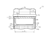
図5又は図6に示すように、ナット55,75は、雌ねじ孔55a,75aを有する。この雌ねじ孔55a,75aの径方向に沿った寸法である、ナット55,75の最大長さL1及び最小長さL2は、電極組立体14の厚みN、及び電流遮断部80を覆うカシメ部材88の外径より大きい。
ナット55,75の最大長さL1とは、平面視六角形状のナット55,75の各々において径方向に対向した角部同士を結ぶ直線の長さである。また、ナット55,75の最小長さL2とは、平面視六角形状のナット55,75の各々において径方向に対向した外側面同士を結ぶ直線の長さである。最大長さL1は、最小長さL2より長い。また、ナット55,75は金属製であり、しかも径方向において厚みを有することから、長側壁12cに比べて剛性が高い。
図6に示すように、ナット55,75の外側面が、ケース11における長側壁12cの外面と面一になっており、各ナット55,75は、径方向に対向する外側面同士を結ぶ直線が、電極組立体14の積層方向に沿うように配置されている。よって、ナット55,75の最小長さL2が電極組立体14の厚みNより大きくなるように、ナット55,75は二次電池10に配置されている。そして、本実施形態では、二次電池10の構成部材であるナット55,75が耐衝撃部材として機能している。
(5)したがって、第2の実施形態によれば、ケース11の長側壁12cに対し、外面側から衝撃が加わっても、ナット55,75が衝撃に耐えて、衝撃がケース11、ひいては電極組立体14に及ぶことを抑制できる。その結果として、電極組立体14において、複数の正極タブ31が重ねられた部位又は複数の負極タブ32が重ねられた部位が歪むことが抑制される。また、上記衝撃によってセパレータ23が破れることが抑制され、これによりセパレータ23の破れた箇所で正極電極21が負極電極22と短絡することも抑制できる。
さらには、ナット55,75が衝撃に耐えて、電流遮断部80に衝撃が及ぶことを抑制できる。その結果として、電流遮断部80を衝撃から保護できる。
(6)ナット55,75は、正極端子15及び負極端子16を蓋13に固定するための部材であり、ナット55,75は、二次電池10の構成部材である。ナット55、75のサイズを比較的大きくすることで、ケース11の外側からの衝撃が電極組立体14及び電流遮断部80に及ぶことを抑制できる。したがって、ケース11に新たに部品を追加することなく衝撃が電極組立体14及び電流遮断部80に及ぶことを抑制できる。
(6)ナット55,75は、正極端子15及び負極端子16を蓋13に固定するための部材であり、ナット55,75は、二次電池10の構成部材である。ナット55、75のサイズを比較的大きくすることで、ケース11の外側からの衝撃が電極組立体14及び電流遮断部80に及ぶことを抑制できる。したがって、ケース11に新たに部品を追加することなく衝撃が電極組立体14及び電流遮断部80に及ぶことを抑制できる。
(7)ナット55,75は金属製であり、耐衝撃性に優れ、しかも、ケース11の外側に配置されている。このため、ナット55,75はケース11の外側からの衝撃を最初に受け止めることができ、電極組立体14及び電流遮断部80に衝撃が及ぶのを好適に抑制することができる。
なお、本実施形態は以下のように変更してもよい。
○ 第1の実施形態において、図7に示すように、導電部材カバー100における本体部101の短辺に沿う長さKを、電極組立体14の厚みNより大きくしてもよい。導電部材カバー100の各突出部102は、長側壁12cの内面に対向する側壁面102aを有する。本体部101の短辺に沿う長さKは、突出部102の側壁面102a同士を最短距離で結ぶ直線の長さである。この実施形態では、二次電池10の構成部材であってケース11内に設けられた導電部材カバー100が耐衝撃部材として機能する。
○ 第1の実施形態において、図7に示すように、導電部材カバー100における本体部101の短辺に沿う長さKを、電極組立体14の厚みNより大きくしてもよい。導電部材カバー100の各突出部102は、長側壁12cの内面に対向する側壁面102aを有する。本体部101の短辺に沿う長さKは、突出部102の側壁面102a同士を最短距離で結ぶ直線の長さである。この実施形態では、二次電池10の構成部材であってケース11内に設けられた導電部材カバー100が耐衝撃部材として機能する。
積層方向に沿った導電部材カバー100の寸法である長さKは、導電部材カバー100がケース11に収容される前とケース11に収容された後との双方において、ケース11(ケース本体12)の内寸以下である。このため、導電部材カバー100が耐衝撃部材として機能する場合であっても、導電部材カバー100をケース本体12内に収容し易い。
また、導電部材カバー100における各突出部102の先端面は、電極組立体14の端面14aから離隔している。
導電部材カバー100は、その短辺の延びる方向において所要の剛性を有している。導電部材カバー100の短辺の延びる方向における剛性は、導電部材カバー100の樹脂材料、導電部材カバー100の厚み、導電部材カバー100の長辺及び短辺の延びる方向への長さ等を変更することで適宜調整可能である。そして、導電部材カバー100の短辺に沿う方向における剛性は、ケース本体12における長側壁12cの剛性より高い。
導電部材カバー100は、その短辺の延びる方向において所要の剛性を有している。導電部材カバー100の短辺の延びる方向における剛性は、導電部材カバー100の樹脂材料、導電部材カバー100の厚み、導電部材カバー100の長辺及び短辺の延びる方向への長さ等を変更することで適宜調整可能である。そして、導電部材カバー100の短辺に沿う方向における剛性は、ケース本体12における長側壁12cの剛性より高い。
このように構成した場合、ケース11の長側壁12cに対し、外面側から衝撃が加わっても、導電部材カバー100が衝撃に耐えて、衝撃がケース11、ひいては電極組立体14に及ぶことを抑制できる。また、導電部材カバー100は、電極組立体14の端面14aから離隔している。このため、衝撃が導電部材カバー100に伝わっても、その衝撃が電極組立体14に伝わることが抑制される。
その結果として、電極組立体14において、複数の正極タブ31が重ねられた部位又は複数の負極タブ32が重ねられた部位が歪むことが抑制される。また、衝撃によってセパレータ23が破れることが抑制され、これによりセパレータ23の破れた箇所で正極電極21が負極電極22と短絡することも抑制できる。
この形態において、導電部材カバー100における本体部101の短辺に沿う長さ(導電部材カバー100の積層方向に沿った寸法)Kを、電極組立体14の厚みNと同じにしてもよい。
○ 第2の実施形態において、導電部材カバー100における本体部101の短辺に沿う長さKを、電流遮断部80のカシメ部材88の外径より大きくして、導電部材カバー100を電流遮断部80を保護する耐衝撃部材として機能させてもよい。導電部材カバー100において、積層方向に沿った寸法である長さKは、導電部材カバー100がケース11に収容される前とケース11に収容された後との双方において、ケース11(ケース本体12)の内寸以下である。また、導電部材カバー100における突出部102の先端面は、電極組立体14の端面14aから離隔している。
○ 第1の実施形態において、ナット55,75の最大長さL1及び最小長さL2を電極組立体14の厚みNより大きくしてもよい。すなわち、耐衝撃用突部59の箇所での第2端子絶縁カバー58の長さMと、ナット55,75の最大長さL1及び最小長さL2との両方を、電極組立体14の厚みNより大きくしてもよい。
加えて、第1の実施形態において、導電部材カバー100における本体部101の短辺に沿う長さKを、電極組立体14の厚みNより大きくしてもよい。
○ 第1の実施形態において、第2端子絶縁カバー58の長さMは、電極組立体14が充電によって積層方向へ膨張した状態で、電極組立体14の厚みNより長く設定されてもよい。この場合、上記(1)~(4)の効果に加えて、二次電池10の製造時で、かつ初期充電の前にケース11の長側壁12cに対し衝撃が加わった場合にも、耐衝撃用突部59が衝撃に耐えて、衝撃が電極組立体14に及ぶことを抑制できる。
○ 第1の実施形態において、第2端子絶縁カバー58の長さMは、電極組立体14が充電によって積層方向へ膨張した状態で、電極組立体14の厚みNより長く設定されてもよい。この場合、上記(1)~(4)の効果に加えて、二次電池10の製造時で、かつ初期充電の前にケース11の長側壁12cに対し衝撃が加わった場合にも、耐衝撃用突部59が衝撃に耐えて、衝撃が電極組立体14に及ぶことを抑制できる。
○ 第1の実施形態において電流遮断部80を省略してもよい。この場合、負極端子16に第1端子絶縁カバー57及び第2端子絶縁カバー58を装着し、第1端子絶縁カバー57及び第2端子絶縁カバー58を、耐衝撃部材とする。そして、第1端子絶縁カバー57及び第2端子絶縁カバー58において、積層方向に沿った寸法を、電極組立体14の厚みN以上とし、且つこれら絶縁カバー57,58がケース11に収容される前とケース11に収容された後との双方において、ケース11(ケース本体12)の内寸以下としてもよい。
○ 第1の実施形態において、第2端子絶縁カバー58に代えて、二次電池10の構成部材である第1端子絶縁カバー57が耐衝撃部材として機能し、その第1端子絶縁カバー57において、電極組立体14の積層方向に沿った寸法を、電極組立体14の厚みN以上としてもよい。この場合、第1端子絶縁カバー57における、積層方向に沿った寸法は、第1端子絶縁カバー57がケース11に収容される前とケース11に収容された後との双方において、ケース11(ケース本体12)の内寸以下である。
○ 第2の実施形態において、ナット55,75の最大長さL1及び最小長さL2のうち、いずれか一方を電極組立体14の厚みNと同じにしてもよい。
○ 第2の実施形態において、電流遮断部80を保護する耐衝撃部材としてのナット55,75に加え、正極端子15を電極組立体14から絶縁する第2端子絶縁カバー58を耐衝撃部材としてケース11内に配置してもよい。そして、第2端子絶縁カバー58において、積層方向に沿った寸法である長さMは、第2端子絶縁カバー58がケース11に収容される前とケース11に収容された後との双方において、ケース11(ケース本体12)の内寸以下である。また、第2端子絶縁カバー58における電極組立体14への対向面は、電極組立体14の端面14aから離隔している。
○ 第2の実施形態において、電流遮断部80を保護する耐衝撃部材としてのナット55,75に加え、正極端子15を電極組立体14から絶縁する第2端子絶縁カバー58を耐衝撃部材としてケース11内に配置してもよい。そして、第2端子絶縁カバー58において、積層方向に沿った寸法である長さMは、第2端子絶縁カバー58がケース11に収容される前とケース11に収容された後との双方において、ケース11(ケース本体12)の内寸以下である。また、第2端子絶縁カバー58における電極組立体14への対向面は、電極組立体14の端面14aから離隔している。
○ 第1の実施形態において、第2端子絶縁カバー58における耐衝撃用突部59の長さMを、電極組立体14の厚みNと同じにしてもよい。
○ 上記各実施形態において、電極組立体14は、積層型に限らず、帯状の正極電極と帯状の負極電極を捲回して層状に積層した捲回型でもよい。捲回型の電極組立体の場合、偏平面が重なる方向を電極組立体の積層方向とする。
○ 上記各実施形態において、電極組立体14は、積層型に限らず、帯状の正極電極と帯状の負極電極を捲回して層状に積層した捲回型でもよい。捲回型の電極組立体の場合、偏平面が重なる方向を電極組立体の積層方向とする。
○ 上記各実施形態において、電極組立体14は、充放電によって積層方向への寸法(厚みN)が変化するタイプであったが、充放電によって積層方向への寸法が変化しないタイプであってもよい。充放電によって積層方向への寸法が変化しない電極組立体を用いた二次電池であっても、第2端子絶縁カバー58の長さM及び導電部材カバー100の長さKは、それらがケース11に収容される前とケース11に収容された後との双方において、ケース11(ケース本体12)の内寸以下である。
○ 上記各実施形態において、二次電池10は、リチウムイオン二次電池であったが、これに限らず、他の二次電池であってもよい。要は、正極活物質と負極活物質との間をイオンが移動するとともに電荷の授受を行う二次電池であればよい。また、上記各実施形態は、蓄電装置としてキャパシタに適用されてもよい。
○ 二次電池10のケース11は底板12aが長方形状となった四角筒状でなくてもよく、ケース11は底板が正方形状となった四角筒状であってもよい。
10…蓄電装置としての二次電池、11…ケース、12c…ケース側壁としての長側壁、13…壁部としての蓋、14…電極組立体、14a…端面、15…電極端子としての正極端子、16…電極端子としての負極端子、21…電極としての正極電極、22…電極としての負極電極、23…セパレータ、40…正極導電部材、52a,72a…ネジ溝、55,75…耐衝撃部材としてのナット、58…耐衝撃部材としての第2端子絶縁カバー、60…負極導電部材、80…電流遮断部、87…端子絶縁カバー、100…導電部材カバー。
Claims (9)
- 異なる極性の電極がセパレータを介して交互に積層された電極組立体と、
前記電極組立体が収容されているケースと、
前記ケースの壁部に固定されている電極端子であって、前記ケースの内側から外側にまで延びるように配置され、かつ前記電極組立体と電力の授受を行う前記電極端子と、
前記電極及び前記セパレータが積層された方向である積層方向に前記ケースの外側から加わる衝撃を受け止めるように構成された耐衝撃部材と、を有し、
前記積層方向に沿った前記耐衝撃部材の寸法が、前記積層方向に沿った前記電極組立体の寸法以上である蓄電装置。 - 異なる極性の電極がセパレータを介して交互に積層された電極組立体と、
前記電極組立体が収容されているケースと、
前記ケースの壁部に固定されている電極端子であって、前記ケースの内側から外側にまで延びるように配置され、かつ前記電極組立体と電力の授受を行う前記電極端子と、
一方の極性を有する前記電極端子と前記電極組立体との間の通電経路上に設けられ、前記ケースの内部圧力が設定圧力を超えたときに前記通電経路を流れる電流を遮断するように構成される電流遮断部と、
前記電極及び前記セパレータが積層された方向である積層方向に前記ケースの外側から加わる衝撃を受け止めるように構成された耐衝撃部材と、を有し、
前記積層方向に沿った前記耐衝撃部材の寸法が、前記積層方向に沿った前記電流遮断部の寸法以上である蓄電装置。 - 前記耐衝撃部材は前記ケース内に収容されるように構成され、前記積層方向に沿った前記耐衝撃部材の寸法は、前記耐衝撃部材が前記ケースに収容される前と前記ケースに収容された後との双方において、前記積層方向に沿った前記ケースの内寸以下である請求項1又は請求項2に記載の蓄電装置。
- 前記電極組立体は、前記壁部の内面に対向する端面を備え、前記耐衝撃部材は、前記電極組立体の前記端面から離隔するように前記ケース内に配置されている請求項1~請求項3のうちいずれか一項に記載の蓄電装置。
- 前記耐衝撃部材は、前記電極端子における前記ケース内に配置される部分に装着される端子絶縁カバーであり、該端子絶縁カバーは前記電極端子を前記電極組立体又は前記ケースから絶縁する請求項1~請求項4のうちいずれか一項に記載の蓄電装置。
- 前記電極端子は、前記ケース外に配置される部分にネジ溝を有し、前記耐衝撃部材は、前記電極端子を前記ケースの壁部に固定するために前記ネジ溝に螺合されるナットである請求項1に記載の蓄電装置。
- 前記蓄電装置は、異なる極性の導電部材を前記ケース内に備え、前記各導電部材は各極性の前記電極を該電極と同じ極性の前記電極端子に電気的に接続し、前記各導電部材は、前記電極端子の固定された前記壁部と前記電極組立体との間に配設されており、前記耐衝撃部材は、異なる極性の前記導電部材同士に跨るように設けられて前記導電部材と前記壁部との接触を規制する導電部材カバーである請求項1~請求項4のうちいずれか一項に記載の蓄電装置。
- 前記ケースは、前記電極組立体における前記積層方向の両端面に対向するケース側壁を備え、前記耐衝撃部材の剛性は、前記ケース側壁の剛性より高い請求項1~請求項7のうちいずれか一項に記載の蓄電装置。
- 前記蓄電装置は二次電池である請求項1~請求項8のうちいずれか一項に記載の蓄電装置。
Priority Applications (1)
| Application Number | Priority Date | Filing Date | Title |
|---|---|---|---|
| JP2016561533A JP6369562B2 (ja) | 2014-11-28 | 2015-11-19 | 蓄電装置 |
Applications Claiming Priority (2)
| Application Number | Priority Date | Filing Date | Title |
|---|---|---|---|
| JP2014-241000 | 2014-11-28 | ||
| JP2014241000 | 2014-11-28 |
Publications (1)
| Publication Number | Publication Date |
|---|---|
| WO2016084693A1 true WO2016084693A1 (ja) | 2016-06-02 |
Family
ID=56074260
Family Applications (1)
| Application Number | Title | Priority Date | Filing Date |
|---|---|---|---|
| PCT/JP2015/082522 Ceased WO2016084693A1 (ja) | 2014-11-28 | 2015-11-19 | 蓄電装置 |
Country Status (2)
| Country | Link |
|---|---|
| JP (1) | JP6369562B2 (ja) |
| WO (1) | WO2016084693A1 (ja) |
Citations (4)
| Publication number | Priority date | Publication date | Assignee | Title |
|---|---|---|---|---|
| JP2000067846A (ja) * | 1998-08-20 | 2000-03-03 | Dainippon Printing Co Ltd | 安全弁付き電池ケース |
| JP2002329493A (ja) * | 2001-05-02 | 2002-11-15 | Mitsubishi Cable Ind Ltd | シート型電池 |
| JP2014059973A (ja) * | 2012-09-14 | 2014-04-03 | Toyota Industries Corp | 蓄電装置 |
| JP2014107147A (ja) * | 2012-11-28 | 2014-06-09 | Toyota Industries Corp | 蓄電装置 |
Family Cites Families (5)
| Publication number | Priority date | Publication date | Assignee | Title |
|---|---|---|---|---|
| JP2009231139A (ja) * | 2008-03-24 | 2009-10-08 | Toshiba Corp | 二次電池 |
| KR101537000B1 (ko) * | 2008-12-22 | 2015-07-16 | 삼성에스디아이 주식회사 | 이차 전지 모듈 |
| JP5490406B2 (ja) * | 2008-12-27 | 2014-05-14 | 三洋電機株式会社 | 車両用の電源装置 |
| US9472802B2 (en) * | 2011-07-25 | 2016-10-18 | Samsung Sdi Co., Ltd. | Secondary battery |
| US9299972B2 (en) * | 2011-09-28 | 2016-03-29 | Samsung Sdi Co., Ltd | Rechargeable battery with separating member between current collector and battery case |
-
2015
- 2015-11-19 WO PCT/JP2015/082522 patent/WO2016084693A1/ja not_active Ceased
- 2015-11-19 JP JP2016561533A patent/JP6369562B2/ja not_active Expired - Fee Related
Patent Citations (4)
| Publication number | Priority date | Publication date | Assignee | Title |
|---|---|---|---|---|
| JP2000067846A (ja) * | 1998-08-20 | 2000-03-03 | Dainippon Printing Co Ltd | 安全弁付き電池ケース |
| JP2002329493A (ja) * | 2001-05-02 | 2002-11-15 | Mitsubishi Cable Ind Ltd | シート型電池 |
| JP2014059973A (ja) * | 2012-09-14 | 2014-04-03 | Toyota Industries Corp | 蓄電装置 |
| JP2014107147A (ja) * | 2012-11-28 | 2014-06-09 | Toyota Industries Corp | 蓄電装置 |
Also Published As
| Publication number | Publication date |
|---|---|
| JPWO2016084693A1 (ja) | 2017-10-05 |
| JP6369562B2 (ja) | 2018-08-08 |
Similar Documents
| Publication | Publication Date | Title |
|---|---|---|
| JP6369564B2 (ja) | 蓄電装置 | |
| JP6760293B2 (ja) | 蓄電装置 | |
| CN105122535B (zh) | 蓄电装置 | |
| JP5812087B2 (ja) | 蓄電装置 | |
| CN103035855A (zh) | 可再充电电池及包括该可再充电电池的车辆 | |
| CN108370020A (zh) | 蓄电装置 | |
| JP6878914B2 (ja) | 蓄電装置 | |
| JP6327069B2 (ja) | 蓄電装置 | |
| KR20160019785A (ko) | 파우치형 이차 전지 및 그 제조 방법 | |
| JP2016139586A (ja) | 蓄電装置 | |
| JP5999021B2 (ja) | 蓄電装置、蓄電モジュール、及び蓄電ユニット | |
| JP6390402B2 (ja) | 蓄電装置 | |
| JP6413758B2 (ja) | 蓄電装置 | |
| JP6476726B2 (ja) | 蓄電装置 | |
| JP5962276B2 (ja) | 蓄電装置 | |
| JP6369562B2 (ja) | 蓄電装置 | |
| EP3641017B1 (en) | Rechargeable battery | |
| JP6354454B2 (ja) | 蓄電装置 | |
| JP2019061746A (ja) | 蓄電装置 | |
| JP2016031851A (ja) | 蓄電装置 | |
| JP6547487B2 (ja) | 蓄電装置モジュール | |
| JP6341026B2 (ja) | 蓄電装置 | |
| US12482883B2 (en) | Power storage device | |
| US10056579B2 (en) | Secondary battery | |
| JP2018037223A (ja) | 蓄電装置 |
Legal Events
| Date | Code | Title | Description |
|---|---|---|---|
| 121 | Ep: the epo has been informed by wipo that ep was designated in this application |
Ref document number: 15863368 Country of ref document: EP Kind code of ref document: A1 |
|
| ENP | Entry into the national phase |
Ref document number: 2016561533 Country of ref document: JP Kind code of ref document: A |
|
| NENP | Non-entry into the national phase |
Ref country code: DE |
|
| 122 | Ep: pct application non-entry in european phase |
Ref document number: 15863368 Country of ref document: EP Kind code of ref document: A1 |