WO2016084637A1 - 車両制御装置及び車両制御方法 - Google Patents
車両制御装置及び車両制御方法 Download PDFInfo
- Publication number
- WO2016084637A1 WO2016084637A1 PCT/JP2015/082075 JP2015082075W WO2016084637A1 WO 2016084637 A1 WO2016084637 A1 WO 2016084637A1 JP 2015082075 W JP2015082075 W JP 2015082075W WO 2016084637 A1 WO2016084637 A1 WO 2016084637A1
- Authority
- WO
- WIPO (PCT)
- Prior art keywords
- vehicle
- lane
- probability
- width
- vehicle control
- Prior art date
- Legal status (The legal status is an assumption and is not a legal conclusion. Google has not performed a legal analysis and makes no representation as to the accuracy of the status listed.)
- Ceased
Links
Images


Classifications
-
- B—PERFORMING OPERATIONS; TRANSPORTING
- B60—VEHICLES IN GENERAL
- B60W—CONJOINT CONTROL OF VEHICLE SUB-UNITS OF DIFFERENT TYPE OR DIFFERENT FUNCTION; CONTROL SYSTEMS SPECIALLY ADAPTED FOR HYBRID VEHICLES; ROAD VEHICLE DRIVE CONTROL SYSTEMS FOR PURPOSES NOT RELATED TO THE CONTROL OF A PARTICULAR SUB-UNIT
- B60W30/00—Purposes of road vehicle drive control systems not related to the control of a particular sub-unit, e.g. of systems using conjoint control of vehicle sub-units
- B60W30/14—Adaptive cruise control
- B60W30/16—Control of distance between vehicles, e.g. keeping a distance to preceding vehicle
-
- B—PERFORMING OPERATIONS; TRANSPORTING
- B60—VEHICLES IN GENERAL
- B60W—CONJOINT CONTROL OF VEHICLE SUB-UNITS OF DIFFERENT TYPE OR DIFFERENT FUNCTION; CONTROL SYSTEMS SPECIALLY ADAPTED FOR HYBRID VEHICLES; ROAD VEHICLE DRIVE CONTROL SYSTEMS FOR PURPOSES NOT RELATED TO THE CONTROL OF A PARTICULAR SUB-UNIT
- B60W40/00—Estimation or calculation of non-directly measurable driving parameters for road vehicle drive control systems not related to the control of a particular sub unit, e.g. by using mathematical models
- B60W40/02—Estimation or calculation of non-directly measurable driving parameters for road vehicle drive control systems not related to the control of a particular sub unit, e.g. by using mathematical models related to ambient conditions
- B60W40/04—Traffic conditions
-
- B—PERFORMING OPERATIONS; TRANSPORTING
- B60—VEHICLES IN GENERAL
- B60R—VEHICLES, VEHICLE FITTINGS, OR VEHICLE PARTS, NOT OTHERWISE PROVIDED FOR
- B60R21/00—Arrangements or fittings on vehicles for protecting or preventing injuries to occupants or pedestrians in case of accidents or other traffic risks
-
- B—PERFORMING OPERATIONS; TRANSPORTING
- B60—VEHICLES IN GENERAL
- B60W—CONJOINT CONTROL OF VEHICLE SUB-UNITS OF DIFFERENT TYPE OR DIFFERENT FUNCTION; CONTROL SYSTEMS SPECIALLY ADAPTED FOR HYBRID VEHICLES; ROAD VEHICLE DRIVE CONTROL SYSTEMS FOR PURPOSES NOT RELATED TO THE CONTROL OF A PARTICULAR SUB-UNIT
- B60W2420/00—Indexing codes relating to the type of sensors based on the principle of their operation
- B60W2420/40—Photo, light or radio wave sensitive means, e.g. infrared sensors
- B60W2420/403—Image sensing, e.g. optical camera
-
- B—PERFORMING OPERATIONS; TRANSPORTING
- B60—VEHICLES IN GENERAL
- B60W—CONJOINT CONTROL OF VEHICLE SUB-UNITS OF DIFFERENT TYPE OR DIFFERENT FUNCTION; CONTROL SYSTEMS SPECIALLY ADAPTED FOR HYBRID VEHICLES; ROAD VEHICLE DRIVE CONTROL SYSTEMS FOR PURPOSES NOT RELATED TO THE CONTROL OF A PARTICULAR SUB-UNIT
- B60W2420/00—Indexing codes relating to the type of sensors based on the principle of their operation
- B60W2420/40—Photo, light or radio wave sensitive means, e.g. infrared sensors
- B60W2420/408—Radar; Laser, e.g. lidar
-
- B—PERFORMING OPERATIONS; TRANSPORTING
- B60—VEHICLES IN GENERAL
- B60W—CONJOINT CONTROL OF VEHICLE SUB-UNITS OF DIFFERENT TYPE OR DIFFERENT FUNCTION; CONTROL SYSTEMS SPECIALLY ADAPTED FOR HYBRID VEHICLES; ROAD VEHICLE DRIVE CONTROL SYSTEMS FOR PURPOSES NOT RELATED TO THE CONTROL OF A PARTICULAR SUB-UNIT
- B60W2554/00—Input parameters relating to objects
- B60W2554/80—Spatial relation or speed relative to objects
- B60W2554/801—Lateral distance
-
- B—PERFORMING OPERATIONS; TRANSPORTING
- B60—VEHICLES IN GENERAL
- B60W—CONJOINT CONTROL OF VEHICLE SUB-UNITS OF DIFFERENT TYPE OR DIFFERENT FUNCTION; CONTROL SYSTEMS SPECIALLY ADAPTED FOR HYBRID VEHICLES; ROAD VEHICLE DRIVE CONTROL SYSTEMS FOR PURPOSES NOT RELATED TO THE CONTROL OF A PARTICULAR SUB-UNIT
- B60W30/00—Purposes of road vehicle drive control systems not related to the control of a particular sub-unit, e.g. of systems using conjoint control of vehicle sub-units
- B60W30/08—Active safety systems predicting or avoiding probable or impending collision or attempting to minimise its consequences
- B60W30/095—Predicting travel path or likelihood of collision
-
- G—PHYSICS
- G08—SIGNALLING
- G08G—TRAFFIC CONTROL SYSTEMS
- G08G1/00—Traffic control systems for road vehicles
- G08G1/16—Anti-collision systems
- G08G1/167—Driving aids for lane monitoring, lane changing, e.g. blind spot detection
Definitions
- the present disclosure relates to a vehicle control technology that is mounted on a vehicle or the like and detects other vehicles existing in front of the vehicle.
- a millimeter wave or the like is transmitted as an exploration wave at regular intervals over a predetermined angle around the vehicle, and the position of the other vehicle is detected by receiving the reflected wave, and the own vehicle follows the detected other vehicle.
- a vehicle control apparatus that performs the above.
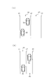
- FIG. 9A shows the positional relationship when the lane width is wide and the host vehicle 30 and the other vehicle 50 travel in the same lane.
- FIG. 9B shows the positional relationship when the lane width is narrow and the other vehicle 50 travels in the adjacent lane 45 of the own lane 44 where the host vehicle 30 is traveling.
- the host vehicle 30 is traveling on the own lane 44 between the first traveling lane line 41 and the second traveling lane line 42, and the other vehicle 50 is also traveling on the own lane 44. ing. At this time, the own vehicle 30 performs follow-up control with the other vehicle 50 as the preceding vehicle.
- the host vehicle 30 is traveling on the host lane 44 between the first travel lane line 41 and the second travel lane line 42, and the other vehicle 50 is in the second travel lane.
- the vehicle travels in the adjacent lane 45 between the line 42 and the third travel lane 43.
- the relative position in the lateral direction between the host vehicle 30 and the other vehicle 50 is close to the example shown in FIG.
- follow-up control may be performed in which the other vehicle 50 traveling in the adjacent lane 45 is the preceding vehicle.
- This disclosure is intended to provide a vehicle control technology that can suppress erroneous detection of other vehicles that are not on the course of the host vehicle.
- the present disclosure is a vehicle control device that is mounted on a host vehicle and controls the host vehicle in accordance with the position of another vehicle existing in front of the host vehicle, in a lateral direction that is a direction orthogonal to the course of the host vehicle.
- Setting means for setting whether or not the other vehicle is located on the course of the own vehicle according to the relative position of the other vehicle with respect to the own vehicle, and the other vehicle is located on the course of the own vehicle by the parameter.
- Determination means for determining whether or not, an acquisition means for acquiring a lane width that is a width of a lane in which the host vehicle travels, an adjustment means that changes a correspondence relationship between a relative position and a parameter based on the lane width; Is provided.
- the host vehicle can determine whether the other vehicle is positioned on the course of the host vehicle based on the relative position of the other vehicle in the lateral direction that is a direction orthogonal to the course of the host vehicle.
- the relative position of the other vehicle with respect to the parameter is associated with a parameter indicating whether the other vehicle is located on the course of the own vehicle. For this reason, in the vehicle control device of the present disclosure, it is possible to determine whether or not the other vehicle is located on the course of the own vehicle based on the parameter associated with the relative position of the other vehicle.
- the vehicle control device of the present disclosure determines whether another vehicle traveling in a lane (adjacent lane) adjacent to the lane in which the host vehicle is traveling (adjacent lane) is selected as the preceding vehicle.
- the lane width is acquired with the above configuration, and the relative position of the other vehicle with respect to the own vehicle and whether the other vehicle is positioned on the course of the own vehicle based on the acquired lane width.
- the correspondence relationship with the parameter indicating is changed.
- FIG. 1 is an overall configuration diagram of the vehicle control device.
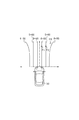
- FIG. 2 is a diagram showing a probability map.
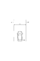
- FIG. 3 is a diagram illustrating the relationship among the host vehicle, the white line, and the lane width.
- FIG. 4 is a diagram showing a corrected probability map.
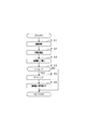
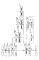
- FIG. 5 is a flowchart showing the processing according to the first embodiment.
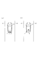
- FIG. 6A is a diagram showing a fusion state
- FIG. 6B is a diagram showing a state that is not a fusion state.
- FIG. 7 is a flowchart showing processing according to the second embodiment.
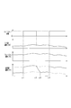
- FIG. 8 is a time chart when the processing according to the second embodiment is executed.
- FIG. 9 is a diagram showing a conventional example.
- a vehicle control device including an object detection device is mounted on a vehicle and has an ACC (Adaptive Cruise Control) function.
- the vehicle control device causes the host vehicle to follow the vehicle so that the distance between the other vehicle detected by the object detection device and the host vehicle becomes a target value of the inter-vehicle distance according to the vehicle speed. Further, the vehicle control device performs control so that the vehicle speed set as the target value is obtained when no other vehicle is detected.
- ACC Adaptive Cruise Control
- the vehicle control device includes a radar device 11, an image acquisition device 12, an inter-vehicle control ECU 13, an engine ECU 14, and a brake ECU 15.
- the inter-vehicle control ECU 13 functions as an object detection device using information acquired from the radar device 11 and the image acquisition device 12, and controls the inter-vehicle distance in cooperation with the engine ECU 14 and the brake ECU 15. To do.
- the radar device 11 and the image acquisition device 12 and the ECUs 13 to 15 are connected to each other via a vehicle-mounted network so that they can communicate with each other.
- An ACC switch 16 is connected to the inter-vehicle control ECU 13.
- a transmission 17, a throttle motor 18, and a throttle sensor 19 are connected to the engine ECU 14.
- a vehicle speed sensor 20 and a brake ACT (actuator) 21 are connected to the brake ECU 15.
- Each of these devices is connected by a dedicated line such as serial communication.
- the radar device 11, the image acquisition device 12, and the ECUs 13 to 15 are information processing devices equipped with a microcomputer, a wire harness interface, and the like.
- the microcomputer includes a CPU, a ROM, a RAM, an I / O port, a CAN communication device, and the like.
- the radar device 11 detects the distance, relative speed, and relative position for each of the other vehicles, and provides the detection result to the inter-vehicle control ECU 13.
- the image acquisition device 12 includes an imaging unit that captures an image of an object or the like, acquires a captured image around the host vehicle, performs predetermined processing, and provides the processing result to the inter-vehicle control ECU 13.
- the inter-vehicle control ECU 13 sends to the engine ECU 14 and the brake ECU 15 an acceleration instruction value for instructing the acceleration of the host vehicle based on the information on the other vehicle transmitted from the radar device 11 and the image acquisition device 12, the current vehicle speed, the acceleration, and the like. Send.
- ACC switch 16 accepts driver's operation for ACC.
- the inter-vehicle control ECU 13 transmits an acceleration instruction value to the engine ECU 14 and the brake ECU 15.
- the driver's operation for ACC includes, for example, ON / OFF of ACC, switching between a mode for keeping the inter-vehicle distance constant and a mode for keeping the vehicle speed constant, an indication value of the vehicle speed, and the like.
- the engine ECU 14 controls the throttle motor 18 while monitoring the throttle opening detected by the throttle sensor 19. For example, the engine ECU 14 determines the throttle opening based on the acceleration instruction value received from the inter-vehicle control ECU 13 and the current vehicle speed based on table data in which the throttle opening is associated with the vehicle speed and the acceleration instruction value. Further, the engine ECU 14 determines whether or not it is necessary to change gear positions (necessity) based on the vehicle speed and the throttle opening, and if necessary, instructs the transmission 17 to change gear positions.
- the brake ECU 15 brakes the host vehicle by controlling the opening / closing and opening of the valve of the brake ACT21.
- the brake ACT 21 controls the acceleration (or deceleration) of the host vehicle by increasing, maintaining, or reducing the wheel cylinder pressure of each wheel by the pressure generated by the pump in the working fluid (for example, oil).
- the brake ECU 15 brakes the host vehicle according to the acceleration instruction value transmitted by the inter-vehicle control ECU 13.
- the radar device 11 is, for example, a radar device that uses a millimeter-wave band high-frequency signal as a transmission wave.
- the radar device 11 detects a position of an object within the detection range by setting a region within a predetermined detection angle in front of the host vehicle as a detection range.
- the radar apparatus 11 includes a transmission / reception unit 11a that transmits a survey wave and receives a reflected wave by a plurality of antennas, and a distance calculation unit 11b that calculates a distance between the host vehicle and another vehicle.
- a relative speed calculation unit 11c that calculates a relative speed between the host vehicle and the other vehicle
- an orientation calculation unit 11d that calculates an orientation of the other vehicle with respect to the host vehicle are provided.
- the distance calculation unit 11b calculates the distance between the host vehicle and the other vehicle based on the transmission time of the exploration wave and the reception time of the reflected wave.
- the relative speed calculation unit 11c calculates the relative speed based on the frequency of the reflected wave reflected by the other vehicle (frequency changed by the Doppler effect).
- the direction calculation unit 11d calculates the direction of the other vehicle based on the phase difference of the reflected waves received by the plurality of antennas.
- the radar device 11 can specify the relative position of the other vehicle with respect to the host vehicle if the position and orientation of the other vehicle can be calculated.
- the radar apparatus 11 transmits the exploration wave to the other vehicle and receives the reflected wave from the other vehicle at predetermined intervals.
- the radar device 11 performs calculation of the reflection position, which is the position where the exploration wave is reflected, and calculation of the relative speed between the host vehicle and the other vehicle at predetermined intervals. As a result, the radar apparatus 11 transmits information including at least the reflection position (position based on the reflected wave) to the inter-vehicle control ECU 13 as the first detection information.
- the image acquisition device 12 includes an imaging unit 12a (imaging means), and the imaging unit 12a is a monocular imaging device, such as a CCD camera, a CMOS image sensor, or a near infrared camera.
- the imaging unit 12a is attached at a predetermined height in the center in the vehicle width direction of the vehicle, and an area (detection range by the radar device 11) that extends in a range of a predetermined angle toward the front of the vehicle from an overhead viewpoint.
- the image processing unit 12b extracts feature points (feature points indicating the presence of other vehicles) in the image captured by the imaging unit 12a. Specifically, the image processing unit 12b extracts edge points based on the luminance information of the image, and performs Hough transform on the extracted edge points.
- the image acquisition device 12 captures an image and extracts feature points at each control cycle that is the same as or different from that of the radar device 11. As a result, the image acquisition device 12 transmits information including at least a feature point extraction result (a position based on the captured image of the detection range) to the inter-vehicle control ECU 13 as second detection information.
- the inter-vehicle control ECU 13 uses the own lane probability S as a parameter for determining whether there is another vehicle in the lane (own lane) in which the own vehicle is traveling for each of the other vehicles present in front of the own vehicle. Is used.
- the own lane probability S will be described with reference to FIG.
- the other vehicle travels over the predetermined range on the virtual plane (virtual coordinate space) located in front of the own vehicle 30.
- a probability map which is a determination area for determining whether or not the object is positioned above, is set. This probability map is set within a detectable range of the radar apparatus 11.
- the own lane probability S is associated with the position (coordinates) on the probability map.
- the inter-vehicle control ECU 13 obtains the own lane probability S of the other vehicle with respect to the own vehicle 30 by mapping the relative position of the other vehicle with respect to the own vehicle 30 to the position on the coordinate space in the probability map.
- the own lane probabilities S of probability values 30 to 90 are associated with each other in a virtual coordinate space indicating the relative position of the other vehicle in front of the own vehicle 30.
- the value is set to gradually decrease as the distance from the position increases in the horizontal direction.
- the inter-vehicle control ECU 13 functions as a setting unit that sets a parameter indicating the relative position of the other vehicle with respect to the host vehicle 30 in the lateral direction orthogonal to the course of the host vehicle 30.
- the own lane probability S on the probability map is set such that the value gradually decreases from the course of the host vehicle 30 toward the lateral direction orthogonal to the course of the host vehicle 30. Furthermore, the own lane probability S is set such that the range of the corresponding position is partially enlarged as the distance from the own vehicle 30 increases. The reason for performing these settings is that the error in the position of the object detected by the radar apparatus 11 increases as the distance from the host vehicle 30 increases.
- the inter-vehicle control ECU 13 calculates the threshold Th that is a predetermined value and the calculated own vehicle probability. The value with the lane probability S is compared.
- the inter-vehicle control ECU 13 selects the other vehicle detected by the radar device 11 as the preceding vehicle used for the follow-up control of the own vehicle 30 when the value of the own lane probability S is equal to or greater than the threshold Th. .
- the inter-vehicle control ECU 13 has already selected the other vehicle detected by the radar device 11 as the preceding vehicle used for the follow-up control of the own vehicle 30 when the own lane probability S is a value less than the threshold Th. Cancel the selection of the vehicle.
- the own lane probability S is set in a plurality of stages so as to be, for example, one step.
- Each stage has a predetermined width in the horizontal direction (hereinafter referred to as “region width”). That is, the own lane probability S is set in a stepwise manner in association with a predetermined region width in the horizontal direction on the virtual coordinate space indicating the relative position of the other vehicle in front of the own vehicle 30. When the position of the other vehicle is included in the area width, the own lane probability S of the area width is associated.
- the reference value of each area width (hereinafter referred to as “reference width”) is determined in advance based on a general lane width of a road, for example, an expressway, on which follow-up control with respect to the preceding vehicle is assumed to be performed. .
- the host lane probability S is 90.
- the host lane probability S is 60.
- the host lane probability S is approximately 40.
- the threshold Th is set as 50
- the other vehicle at the position P1 or the position P2 is selected as the preceding vehicle because the own lane probability S is equal to or higher than the threshold Th (S ⁇ 50).
- the other vehicle at the position P3 is not selected as the preceding vehicle because the own lane probability S is less than the threshold Th (S ⁇ 50) (if the vehicle is selected as the preceding vehicle, the selection is canceled).
- the own lane probability S is a threshold value. It is set to be equal to or greater than Th. That is, the threshold Th is set so that the range in which the own lane probability S is equal to or greater than the threshold Th is within the lane width, and the range in which the own lane probability S is less than the threshold Th is outside the lane width.
- the specific probability value of the own lane probability S is shown in the probability map of FIG. 2, this is merely an example. That is, the probability map is such that the other vehicle is selected as the preceding vehicle as the lateral relative position of the other vehicle with respect to the own vehicle 30 moves toward a position near the course of the own vehicle 30 (near the center of the own lane).
- the own lane probability S may be set.
- the other vehicle when it is determined whether another vehicle should be selected as a preceding vehicle using the probability map shown in FIG. 2 on a road having a narrower lane width than expected, the other vehicle is a lane in which the host vehicle 30 is traveling.
- the vehicle is selected as the preceding vehicle even though the vehicle is traveling in a lane (adjacent lane) adjacent to (own lane).
- the width of the own lane is such that the own lane probability S falls within the range of 60 or more
- the lane probability S may be greater than or equal to a threshold Th (S ⁇ 50). That is, when the position of the other vehicle is detected at the position P2 in FIG.
- the own lane probability S is 60 even though the detected other vehicle is traveling in the adjacent lane, and the other vehicle is traveling in the adjacent lane.
- the vehicle is selected as the preceding vehicle.
- the follow-up control for the other vehicle traveling in the adjacent lane is performed, and the accuracy of the vehicle control is lowered.
- the probability map is corrected according to the lane width. Specifically, feature points are extracted based on luminance information of an image (road image) captured by the imaging unit 12a, and a white line (traveling division line) drawn on the road ahead of the host vehicle 30 is recognized. . At this time, as shown in FIG. 3, when both the left white line 41 and the right white line 42 are detected in the lane in which the host vehicle 30 is traveling (the own lane), between the left white line 41 and the right white line 42. A lane width L1 that is a distance of is calculated.
- the lane width L1 may be obtained by, for example, obtaining the lane width value at a plurality of locations, and using the average value of the plurality of width values as the value of the lane width L1, or the lane width L1 at a predetermined distance from the host vehicle 30.
- the width value may be used as the value of the lane width L1.
- the correction of the probability map using the lane width L1 is performed by reducing the area width of each area associated with the own lane probability S in the probability map in the lateral direction orthogonal to the course of the own vehicle 30. Is called. By doing this, even if the relative position of the other vehicle with respect to the own vehicle 30 is the same, the own lane probability S using the corrected probability map is smaller than the own lane probability S using the corrected probability map. Takes a value. As a result, when the corrected probability map is used, even if the relative position of the other vehicle with respect to the host vehicle 30 is the same, it is difficult for the other vehicle to be selected as the preceding vehicle.
- FIG. 4 shows an example of a probability map corrected by using the lane width L1.
- the area width of the own lane probability S in the probability map is reduced in the lateral direction orthogonal to the course of the own vehicle 30.
- the own lane probability S is approximately 75 at the position P1
- the own lane probability S is approximately 40 at the position P2. Therefore, when another vehicle is detected at the position P2, the own lane probability S is less than the threshold Th (S ⁇ 50), and the detected other vehicle is not selected as the preceding vehicle.
- FIG. 5 is a flowchart showing a process executed by the inter-vehicle control ECU 13 according to the present embodiment. The process of FIG. 5 is repeatedly executed at a predetermined control cycle.
- the inter-vehicle control ECU 13 first acquires an image (road image) captured by the imaging unit 12a (S101), extracts feature points of a white line (traveling line) from the luminance information of the image, and the like. Is recognized (S102). When recognizing the white line, the inter-vehicle control ECU 13 calculates a lane width L1 which is the width between the left white line 41 and the right white line 42 (S103). At this time, the inter-vehicle control ECU 13 functions as an acquisition unit that acquires the lane width L1 of the lane (own lane) in which the host vehicle 30 is traveling.
- the lane width L1 may be obtained, for example, by obtaining lane width values at a plurality of locations, and using an average value of the plurality of width values as the value of the lane width L1, or being separated from the host vehicle 30 by a predetermined distance.
- the width value of the position lane may be used as the value of the lane width L1.
- the processing of S101 and S102 may be executed by the image processing unit 12b of the image acquisition device 12.
- the inter-vehicle control ECU 13 determines whether or not the calculated lane width L1 is equal to or smaller than the reference width L (S104).
- the reference width L is a value determined in advance based on a general lane width such as a road on which the follow-up control for the preceding vehicle is assumed, for example, an expressway.
- the inter-vehicle control ECU 13 determines that the lane width L1 is larger than the reference width L (S104: NO), the series of processing ends. On the other hand, when determining that the lane width L1 is equal to or less than the reference width L (S104: YES), the inter-vehicle control ECU 13 calculates a correction coefficient K used when correcting the area width of the own lane probability S in the probability map (S105). .
- the correction coefficient K is calculated by dividing the lane width L1 by the reference width L.
- the inter-vehicle control ECU 13 calculates the corrected area width by multiplying the calculated correction coefficient K by the reference value of each area width of the own lane probability S, and corrects the area width of the own lane probability S in the probability map. (S106). Thereafter, the inter-vehicle distance control ECU 13 ends the series of processes.
- the inter-vehicle control ECU 13 functions as an adjusting unit that adjusts the area width of the own lane probability S in the probability map based on the lane width L1. That is, the inter-vehicle control ECU 13 changes the correspondence relationship between the relative position of the other vehicle with respect to the host vehicle 30 and the parameter indicating whether the other vehicle is located on the course of the host vehicle 30 based on the lane width L1. It functions as an adjustment means.
- the inter-vehicle control ECU 13 executes the processing shown in the flowchart of FIG. 5, and then based on the corrected probability map and the relative position of the other vehicle with respect to the own vehicle 30, the own lane of the other vehicle with respect to the own vehicle 30. Probability S is calculated. Then, the inter-vehicle control ECU 13 performs a determination process as to whether or not the calculated own lane probability S is greater than or equal to the threshold Th. The inter-vehicle control ECU 13 performs processing of selecting another vehicle as a preceding vehicle or excluding it as a selection target based on the determination result. Thus, the inter-vehicle control ECU 13 functions as a determination unit that determines whether or not another vehicle is positioned on the course of the host vehicle 30 based on the set parameters.
- the vehicle control device has the following effects due to the above configuration.
- the vehicle control device it is possible to determine whether or not the other vehicle is positioned on the course of the host vehicle 30 based on the relative position of the other vehicle in the lateral direction that is a direction orthogonal to the course of the host vehicle 30.
- the relative position of the other vehicle with respect to the own vehicle 30 and the parameter indicating whether the other vehicle is located on the course of the own vehicle 30 are associated with each other. More specifically, in the vehicle control device according to the present embodiment, the relative position of the other vehicle with respect to the own vehicle 30 and the own lane probability that is a parameter indicating whether the other vehicle is located on the course of the own vehicle 30.
- a probability map in which S is associated is used.
- the own lane probability S is set in a plurality of stages, and the set own lane probability S includes a lateral direction that is orthogonal to the course of the host vehicle 30 in each stage.
- the region width is as follows. Therefore, in the present embodiment, by mapping the relative position of the other vehicle to the own vehicle 30 in the coordinate space on the probability map, the own lane probability S can be associated with the position of the other vehicle. Thereby, in the vehicle control apparatus which concerns on this embodiment, it can determine whether the other vehicle is a preceding vehicle located on the course of the own vehicle 30 by the own lane probability S matched with the position of the other vehicle. .
- the vehicle control device In this time, on a road whose lane width is narrower than expected, there is a possibility that another vehicle traveling in a lane (adjacent lane) adjacent to the lane in which the host vehicle 30 is traveling (adjacent lane) may be selected as the preceding vehicle.
- the lane width L1 is acquired, and the area width of each own lane probability S in the probability map is changed based on the lane width L1 and the reference width L. That is, in the vehicle control device according to the present embodiment, based on the lane width L1, the relative position of the other vehicle with respect to the own vehicle 30 and the parameter indicating whether the other vehicle is located on the course of the own vehicle 30 The correspondence is changed.
- the vehicle control device it is possible to suppress the determination that another vehicle traveling in the adjacent lane exists on the course of the host vehicle 30 when the lane width L1 is narrow. That is, in the vehicle control device according to the present embodiment, erroneous detection of other vehicles that are not located on the course of the host vehicle 30 can be suppressed.
- Second Embodiment The overall configuration of the vehicle control device according to this embodiment is the same as that of the vehicle control device according to the first embodiment, and the control executed by the inter-vehicle control ECU 13 is partially different.
- position information of other vehicles is acquired by the radar device 11 (first position detection means) and the image acquisition device 12 (second position detection means).
- the radar apparatus 11 calculates the position of the other vehicle by receiving the reflected wave from the other vehicle.
- the image acquisition device 12 calculates the position of the other vehicle by acquiring feature points of an image obtained by imaging the other vehicle.
- the reflection position (first position) calculated by the radar apparatus 11 is calculated based on the transmission / reception time of the radar wave. Therefore, the radar device 11 can accurately calculate the position of the other vehicle.
- the reflected wave reflected at the center of the rear part of the other vehicle may be used for position calculation, or the reflected wave reflected by a part other than the rear part of the other vehicle (left and right ends, etc.) is received. Sometimes. As a result, in the radar apparatus 11, a deviation occurs in the calculated position.
- the image acquisition device 12 can accurately determine whether or not another vehicle exists by extracting feature points of the captured image.
- the imaging unit 12a is attached at a predetermined height, and the other vehicle is imaged from the overhead view point at the attachment position, and the feature points of the other vehicle are extracted based on the captured image. Yes. Therefore, in the image acquisition device 12, even if the position of the feature point of the captured image is corrected based on the mounting position of the imaging unit 12a, a deviation from the actual position may occur. Therefore, the image acquisition device 12 can accurately determine the presence or absence of the other vehicle, but the image position (second position) that is the position of the other vehicle calculated based on the feature point of the captured image and the actual position. May cause deviation.
- the value indicating the deviation between the reflection position calculated by the radar device 11 and the image position calculated by the image acquisition device 12 (hereinafter referred to as “deviation amount”) is small, another vehicle may exist at that position. High nature. In the present embodiment, such a state where the amount of deviation is small is referred to as a fusion state. That is, the state in which the position of the other vehicle can be accurately acquired by the radar device 11 and the image acquisition device 12 is referred to as a fusion state.
- the position obtained based on the reflection position and the image position at that time is set as the fusion position, and the fusion probability is obtained using the fusion position and the probability map.
- the fusion probability is obtained by the same means (method) as the own lane probability S described in the first embodiment.
- the millimeter wave probability is obtained using the reflection position and the probability map at that time.
- the millimeter wave probability is obtained by the same means (method) as the own lane probability S described in the first embodiment.
- FIG. 6A shows an example of the reflection position P and the image position Q of the other vehicle 50 in the fusion state
- FIG. 6B shows the other vehicle 50 in the fusion state.
- An example of the reflection position P and the image position Q is shown.
- the fusion position F is calculated based on the reflection position P and the image position Q
- the fusion probability is calculated based on the calculated fusion position F and the set probability map. calculate.
- the vehicle control apparatus calculates the millimeter wave probability based on the reflection position P and the probability map.
- FIG. 7 is a flowchart showing a series of processes in the inter-vehicle control ECU 13 according to the present embodiment. The process of FIG. 7 is repeatedly executed at a predetermined control cycle.
- the inter-vehicle control ECU 13 first acquires information on the reflection position P from the radar device 11 (S201), and acquires information on the image position Q from the image acquisition device 12 (S202). The inter-vehicle control ECU 13 determines whether or not it is in the fusion state based on the determination result of whether or not the deviation between the acquired reflection position P and the image position Q is less than a predetermined distance (the deviation amount is less than a predetermined value). (S203). When the inter-vehicle control ECU 13 determines that the vehicle is in the fusion state (S203: YES: when the deviation amount is less than a predetermined value), the fusion probability is set as the own lane probability S (S204). At this time, the inter-vehicle control ECU 13 calculates the fusion position F based on the reflection position P and the image position Q, and calculates the fusion probability based on the calculated fusion position F and the set probability map.
- the inter-vehicle control ECU 13 determines that the vehicle is not in the fusion state (S203: NO: when the deviation amount is a predetermined value or more)
- the inter-vehicle control ECU 13 acquires the own lane probability S and the millimeter wave probability one control cycle before, It is determined whether or not the own lane probability S is larger than the millimeter wave probability one control cycle before (S205).
- the millimeter wave probability is calculated based on the reflection position P and the probability map when not in the fusion state.
- the inter-vehicle control ECU 13 determines that the own lane probability S is larger than the millimeter wave probability (S205: YES), and subtracts a predetermined value from the own lane probability S, thereby bringing the own lane probability S closer to the millimeter wave probability ( S206). On the other hand, when determining that the own lane probability S is equal to or less than the millimeter wave probability (S205: NO), the inter-vehicle control ECU 13 determines whether the own lane probability S is a value smaller than the millimeter wave probability (S207).
- the inter-vehicle control ECU 13 When determining that the own lane probability S is smaller than the millimeter wave probability (S207: YES), the inter-vehicle control ECU 13 adds the predetermined value to the own lane probability S, thereby bringing the own lane probability S closer to the millimeter wave probability. (S208). On the other hand, when determining that the own lane probability S is the same value as the millimeter wave probability (S207: NO), the inter-vehicle control ECU 13 sets the millimeter wave probability as the own lane probability S (S209). Thus, in the present embodiment, the own lane probability S is gradually changed from the fusion probability to the value of the millimeter wave probability by the processing of S205 to S209.
- the own lane probability S when the own lane probability S after the subtraction is smaller than the millimeter wave probability, the own lane probability S is set as the millimeter wave probability.
- the own lane probability S after the addition when the own lane probability S after the addition is larger than the millimeter wave probability, the own lane probability is set as the millimeter wave probability.
- the inter-vehicle control ECU 13 compares the calculated own lane probability S with the threshold Th and determines whether or not the own lane probability S is equal to or greater than the threshold Th (S210). When it is determined that the calculated own lane probability S is equal to or greater than the threshold Th (S210: YES), the inter-vehicle control ECU 13 determines whether or not the target vehicle has already been selected as a preceding vehicle (S211). When determining that the target vehicle is a vehicle that has already been selected as the preceding vehicle (S211: YES), the inter-vehicle control ECU 13 ends the series of processes.
- the inter-vehicle control ECU 13 selects the target vehicle as the preceding vehicle, and ends the series of processes (S212).
- the inter-vehicle control ECU 13 determines whether the target vehicle is already selected as a preceding vehicle (S213).
- the inter-vehicle control ECU 13 excludes the target vehicle from the preceding vehicle and ends the series of processes (S214).
- the inter-vehicle control ECU 13 determines that the target vehicle is not the vehicle selected as the preceding vehicle (S213: NO), the series of processing ends. In this way, the inter-vehicle control ECU 13 executes the processes of S203 to S209, and based on at least one of the reflection position P and the image position Q according to the amount of deviation between the reflection position P and the image position Q, It functions as parameter acquisition means for acquiring the value of the own lane probability S.
- FIG. 8 is a time chart showing changes in the own lane probability S when the processing shown in the flowchart is executed.
- FIG. 8 shows a case where the fusion position F is closer to the front position of the host vehicle 30 than the millimeter wave position, and the fusion probability is higher than the millimeter wave probability.
- the initial state is not the fusion state, and in the subsequent state transition, the fusion state is indicated by “1”, and the non-fusion state (a state that is not the fusion state) is indicated by “0”.
- the fusion probability and the millimeter wave probability are respectively shown by broken lines.
- the deviation amount between the reflection position P and the image position Q is small, and it is determined that the state is a fusion state.
- the value of the own lane probability S changes from the value of the millimeter wave probability to the value of the fusion probability.
- the amount of divergence between the reflection position P and the image position Q increases, and it is determined that the fusion state is not established (non-fusion state).
- the value of the own lane probability S gradually changes from the fusion probability value to the millimeter wave probability value.
- the gradual change from the fusion probability value to the millimeter wave probability value continues until time t3 when the value of the own lane probability S becomes the millimeter wave probability value.
- the fusion state is determined again.
- the value of the own lane probability S changes from the value of the millimeter wave probability to the value of the fusion probability.
- FIG. 8 shows an example in which the fusion probability is higher than the millimeter wave probability
- the same control is performed even when the fusion probability is lower than the millimeter wave probability.
- the reason why the same control can be performed is that when the reflection position P is closer to the front position of the host vehicle 30 than the fusion position F, the millimeter wave probability calculated based on the reflection position P is higher than the fusion probability. Because.
- the following vehicle control device can be configured.
- the vehicle control device is a device that is mounted on the host vehicle 30 and controls the host vehicle 30 according to the position of the other vehicle 50 existing in front of the host vehicle 30.
- the vehicle control apparatus includes a radar apparatus 11 that functions as first position detection means.
- the radar apparatus 11 receives the reflected wave from the other vehicle 50 by transmitting the exploration wave, and sets the position based on the reflected wave to a reflection position P (first position) that is a relative position of the other vehicle 50 with respect to the own vehicle 30. Get as.
- the vehicle control device includes an image acquisition device 12 that functions as second position detection means.
- the image acquisition device 12 images the other vehicle 50 by the imaging unit 12a (imaging means), and sets the position based on the captured image to an image position Q (second position) that is a relative position of the other vehicle 50 with respect to the host vehicle 30.
- the vehicle control apparatus includes an inter-vehicle control ECU 13 that functions as a setting unit, a parameter acquisition unit, and a determination unit.
- the inter-vehicle control ECU 13 functions as a setting unit to set the own lane probability S corresponding to a parameter indicating the relative position of the other vehicle 50 with respect to the own vehicle 30 in the lateral direction that is a direction orthogonal to the course of the own vehicle 30. To do.
- the inter-vehicle control ECU 13 functions as parameter acquisition means, and acquires the own lane probability S based on the reflection position P and the image position Q when the deviation amount between the reflection position P and the image position Q is less than a predetermined value. . Further, the inter-vehicle control ECU 13 obtains the own lane probability S based on the reflection position P when the deviation amount between the reflection position P and the image position Q is a predetermined value or more. The inter-vehicle control ECU 13 functions as a determination unit, and determines whether or not the other vehicle 50 is located on the course of the own vehicle 30 based on the acquired own lane probability S.
- the inter-vehicle control ECU 13 acquires the own lane probability S for each predetermined control cycle. Then, the inter-vehicle distance control ECU 13 acquires the own lane probability S as follows. When the amount of divergence between the reflection position P and the image position Q changes from a state greater than or equal to a predetermined value to a state less than the predetermined value, the own lane probability S is acquired based on the first position and the second position. .
- the reflection position is calculated from the value of the own lane probability S acquired one control period before.
- a value approaching the value of the millimeter wave probability based on P by a predetermined value is acquired as the own lane probability S.
- the vehicle control device has the following effects due to the above configuration.
- the radar device 11 can calculate the position with high accuracy. Further, the image acquisition device 12 can accurately determine the presence or absence of a vehicle. In the fusion state in which the reflection position P and the image position Q acquired from each of the radar apparatus 11 and the image acquisition apparatus 12 having such characteristics are located in the vicinity, the reflection position P and the image position Q The possibility that the same vehicle is detected is high. Therefore, in the vehicle control device according to the present embodiment, the fusion position F is calculated based on the reflection position P and the image position Q, and the other vehicle 50 is calculated based on the calculated fusion position F and the set probability map. Can be accurately determined whether or not the vehicle is located on the course of the host vehicle 30.
- the reflection position P when it is not a fusion state in which the reflection position P and the image position Q are separated (in a non-fusion state), the reflection position P may be the same as the position where the other vehicle 50 exists. Therefore, in the vehicle control device according to the present embodiment, it is possible to determine whether or not the other vehicle 50 is located on the course of the host vehicle 30 based on the reflection position P and the probability map.
- the reflection position P and the image position Q are located in the vicinity, and the position of the other vehicle 50 can be detected with high accuracy. Therefore, in the vehicle control device according to the present embodiment, when the transition from the non-fusion state to the fusion state is performed, the other vehicle 50 is positioned on the course of the own vehicle 30 by immediately setting the own lane probability S as the fusion probability. The accuracy of determining whether or not can be improved. On the other hand, when the transition is made from the fusion state to the non-fusion state, the reflection position P is displaced. Thereby, the transition to the fusion state may occur again.
- the vehicle control device when the transition is made from the fusion state to the non-fusion state, the value of the own lane probability S is gradually changed so as to approach the value of the millimeter wave probability. It is possible to suppress a situation in which selection and cancellation of the preceding vehicle frequently occur.
- the region width of the own lane probability S in the probability map is corrected (the processing in S104 to S106), but the present invention is not limited to this.
- the correction of the area width of the own lane probability S in the probability map is, for example, by calculating the correction coefficient K by dividing the lane width L1 by the reference width L even when the lane width L1 is larger than the reference width L.
- the correction may be performed based on the calculated correction coefficient K. That is, the process of S104 shown in the flowchart of FIG. 5 may be omitted.
- the region width of all the lane probabilities S in the probability map is corrected.
- the correction of the area width of the own lane probability S in the probability map may be performed, for example, by correcting only a part of the area width.
- the other vehicle 50 located near the course of the host vehicle 30 should be selected as the preceding vehicle. Therefore, the area width of the own lane probability S in the probability map may not be corrected for an area in the vicinity of the course of the own vehicle 30, for example, an area within the range of the own vehicle 30.
- the acquisition method of the correction coefficient K in the first embodiment is not limited to the configuration in which the lane width L1 is divided by the reference width L.
- the correction coefficient K is obtained by associating the correction coefficient K with the lane width L1 in advance using, for example, a data table or the like, and acquiring the associated correction coefficient K according to the calculated lane width L1. It is good.
- the lane width L1 is calculated by recognizing the white line, but the present invention is not limited to this.
- the calculation of the lane width L1 may be a configuration in which the road shape is recognized based on travel lane lines other than the white line, and the lane width L1 is calculated from the recognition result.
- the lane width L1 is calculated by recognizing a road shape based on a structure (stationary object) on the road provided along a lane such as a guard rail or a median strip, and calculating the lane width L1 from the recognition result. It is good.
- the flowcharts shown in the first embodiment and the second embodiment are merely examples of processing executed by the inter-vehicle control ECU 13. Therefore, it is possible to change the execution order of the processes or to change some of the processing contents.
Landscapes
- Engineering & Computer Science (AREA)
- Mechanical Engineering (AREA)
- Automation & Control Theory (AREA)
- Transportation (AREA)
- Physics & Mathematics (AREA)
- Mathematical Physics (AREA)
- Traffic Control Systems (AREA)
Abstract
自車両に搭載され、自車両の前方に存在する他車両の位置に応じて自車両を制御する車両制御装置13であって、自車両の進路に直交する方向である横方向における、自車両に対する他車両の相対位置に応じて、他車両が自車両の進路上に位置するか否かを示すパラメータを設定する設定手段と、パラメータにより、他車両が自車両の進路上に位置するか否かを判定する判定手段と、自車両が走行する車線の幅である車線幅を取得する取得手段と、車線幅に基づいて、相対位置とパラメータとの対応関係を変化させる調整手段と、を備える。
Description
本開示は、車両等に搭載され、車両前方に存在する他車両の検知を行う車両制御技術に関する。
従来では、車両周囲の所定角度にわたり、一定期間ごとにミリ波などを探査波として送信し、反射波を受信することによって他車両の位置を検知し、検知した他車両に自車両を追従させる制御を行う車両制御装置が知られている。
この種の車両制御装置には、特許文献1に記載の車両制御装置がある。特許文献1に記載の車両制御装置では、自車線(自車両が走行中の車線)及び隣接車線(自車線に隣接する車線)を走行する他車両を検出し、隣接車線を走行する他車両が自車線に進入したか否かを判定している。また、特許文献1に記載の車両制御装置では、自車線を走行する他車両が自車線から離脱したか否かを判定している。このとき、自車線を走行する他車両が横方向へと移動し、自車線から離脱を行う挙動を開始した場合には、他車両の位置の検知幅を縮小することにより、他車両が検知範囲からの早い離脱を促している。一方、隣接車線を走行する他車両が横方向へと移動し、自車線へと移動する場合には、他車両の位置の検知幅を拡大することにより、他車両が検知範囲へのより早い進入を促している。
特許文献1に記載の車両制御装置では、自車線を走行する他車両を検知する。しかし、車線幅が想定よりも狭い場合には、隣接車線を走行する他車両が、自車線を走行していると判定することがある。
具体的には図9を用いて説明する。図9(a)は、車線幅が広く、自車両30と他車両50とが同一車線を走行する場合の位置関係を示す。また、図9(b)は、車線幅が狭く、他車両50が、自車両30が走行中の自車線44の隣接車線45を走行する場合の位置関係を示す。
図9(a)で示す例では、自車両30は第1走行区画線41と第2走行区画線42との間の自車線44を走行しており、他車両50も自車線44を走行している。このとき、自車両30では、他車両50を先行車両とする追従制御がなされる。
一方、図9(b)で示す例では、自車両30は第1走行区画線41と第2走行区画線42との間の自車線44を走行しており、他車両50は第2走行区画線42と第3走行区画線43との間の隣接車線45を走行している。このとき、車線幅が狭いため、自車両30と他車両50との横方向の相対的な位置は、図9(a)で示した例と近い位置となる。そのため、自車両30では、隣接車線45を走行する他車両50を先行車両とする追従制御がなされることがある。
本開示は、自車両の進路上に位置しない他車両についての誤った検知を抑制できる車両制御技術を提供することを目的とする。
本開示は、自車両に搭載され、自車両の前方に存在する他車両の位置に応じて自車両を制御する車両制御装置であって、自車両の進路に直交する方向である横方向における、自車両に対する他車両の相対位置に応じて、他車両が自車両の進路上に位置するか否かを示すパラメータを設定する設定手段と、パラメータにより、他車両が自車両の進路上に位置するか否かを判定する判定手段と、自車両が走行する車線の幅である車線幅を取得する取得手段と、車線幅に基づいて、相対位置とパラメータとの対応関係を変化させる調整手段と、を備える。
本開示の車両制御装置では、自車両の進路に直交する方向である横方向における他車両の相対位置により、他車両が自車両の進路上に位置するか否かを判定できるように、自車両に対する他車両の相対位置と、他車両が自車両の進路上に位置するか否かを示すパラメータとを対応付けている。このため、本開示の車両制御装置では、他車両の相対位置に対応付けられたパラメータにより、他車両が自車両の進路上に位置するか否かを判定できる。このとき、車線幅が想定よりも狭い道路では、自車両が走行中の車線(自車線)に隣接する車線(隣接車線)を走行する他車両を、先行車両として選択する可能性がある。この点、本開示の車両制御装置では、上記構成により、車線幅を取得し、取得した車線幅により、自車両に対する他車両の相対位置と、他車両が自車両の進路上に位置するか否かを示すパラメータとの対応関係を変化させている。これにより、本開示の車両制御装置では、車線幅が狭い場合において、隣接車線を走行する他車両が自車両の進路上に存在すると判定されることを抑制できる。つまり、本開示の車両制御装置では、自車両の進路上に位置しない他車両についての誤った検知を抑制できる。
以下、各実施形態を図面に基づいて説明する。なお、以下の各実施形態において、互いに同一もしくは均等である部分には、図中、同一符号を付しており、同一符号の部分についてはその説明を援用する。
<第1実施形態>
本開示の第1実施形態について図面を参照しながら説明する。物体検知装置を備える車両制御装置は、車両に搭載されており、ACC(Adaptive Cruise Control)機能を有している。車両制御装置は、ACC機能により、物体検知装置で検出した他車両と自車両との距離が、車速に応じた車間距離の目標値となるように、自車両を追従走行させる。また、車両制御装置は、他車両が検出されない場合、目標値として設定された車速となるように制御を行う。
本開示の第1実施形態について図面を参照しながら説明する。物体検知装置を備える車両制御装置は、車両に搭載されており、ACC(Adaptive Cruise Control)機能を有している。車両制御装置は、ACC機能により、物体検知装置で検出した他車両と自車両との距離が、車速に応じた車間距離の目標値となるように、自車両を追従走行させる。また、車両制御装置は、他車両が検出されない場合、目標値として設定された車速となるように制御を行う。
図1において、本実施形態に係る車両制御装置は、レーダ装置11、画像取得装置12、車間制御ECU13、エンジンECU14、及び、ブレーキECU15を備えている。そして、車両制御装置では、車間制御ECU13が、レーダ装置11及び画像取得装置12から取得した情報を用いて物体検知装置として機能し、エンジンECU14及びブレーキECU15と協働して車間距離の制御を実施する。
レーダ装置11及び画像取得装置12と各ECU13~15とは、車載ネットワークを介して相互に通信が可能に接続されている。車間制御ECU13にはACCスイッチ16が接続されている。エンジンECU14には、トランスミッション17、スロットルモータ18、及びスロットルセンサ19が接続されている。ブレーキECU15には、車速センサ20及びブレーキACT(アクチュエータ)21が接続されている。これらのデバイスは、それぞれシリアル通信等の専用線で接続されている。
レーダ装置11、画像取得装置12、及び各ECU13~15は、マイコンやワイヤハーネスのインタフェース等を搭載した情報処理装置である。また、マイコンは、CPU、ROM、RAM、I/Oポート、及びCAN通信装置等を備える。
レーダ装置11は、他車両ごとに距離、相対速度、及び相対位置を検出し、その検出結果を車間制御ECU13に提供する。画像取得装置12は、物体等の画像を撮像する撮像手段を有し、自車両の周囲の撮像画像を取得して所定の処理を行い、その処理結果を車間制御ECU13に提供する。
車間制御ECU13は、レーダ装置11及び画像取得装置12から送信される他車両の情報や、現在の車速、及び加速度等に基づき、自車両の加速度を指示する加速度指示値をエンジンECU14及びブレーキECU15に送信する。
ACCスイッチ16は、ACCについて運転者の操作を受け付ける。これを受けて、車間制御ECU13は、エンジンECU14及びブレーキECU15へ加速度指示値を送信する。なお、ACCについての運転者の操作は、例えば、ACCのON/OFF、車間距離を一定に保つモードと車速を一定に保つモードとの切り替え、車速の指示値等である。
エンジンECU14は、スロットルセンサ19が検出するスロットル開度を監視しながら、スロットルモータ18を制御する。例えば、エンジンECU14は、車速と加速度指示値とにスロットル開度が対応づけられたテーブルデータに基づき、車間制御ECU13から受信した加速度指示値と現在の車速とに応じてスロットル開度を決定する。また、エンジンECU14は、車速とスロットル開度とに基づき、変速段の切り替えが必要か否か(必要性)を判断し、必要であればトランスミッション17に変速段を指示する。
ブレーキECU15は、ブレーキACT21のバルブの開閉及び開度を制御することで自車両を制動する。ブレーキACT21は、ポンプが作動流体(例えば油等)に発生させた圧力により、各車輪のホイルシリンダ圧を増圧・維持・減圧することで、自車両の加速度(又は減速度)を制御する。ブレーキECU15は、車間制御ECU13が送信する加速度指示値に応じて自車両を制動する。
レーダ装置11は、例えば、ミリ波帯の高周波信号を送信波とするレーダ装置であり、自車両の前方において、所定の検知角に入る領域を検知範囲とし、検知範囲内の物体の位置を検出する。具体的には、レーダ装置11は、探査波を送信し、複数のアンテナにより反射波を受信する送受信部11aと、自車両と他車両との距離を算出する距離算出部11bとを備えている。また、自車両と他車両との相対速度を算出する相対速度算出部11cと、他車両の自車両に対する方位を算出する方位算出部11dとを備えている。距離算出部11bは、探査波の送信時刻と反射波の受信時刻とにより、自車両と他車両との距離を算出する。相対速度算出部11cは、他車両に反射された反射波の周波数(ドップラー効果により変化した周波数)により、相対速度を算出する。方位算出部11dは、複数のアンテナが受信した反射波の位相差により、他車両の方位を算出する。なお、レーダ装置11では、他車両の位置及び方位が算出できれば、自車両に対する他車両の相対位置を特定できる。レーダ装置11は、他車両への探査波の送信、及び、他車両からの反射波の受信を、所定周期ごとに行う。また、レーダ装置11は、探査波が反射された位置である反射位置の算出、及び、自車両と他車両との相対速度の算出を、所定周期ごとに行う。その結果、レーダ装置11は、少なくとも反射位置(反射波に基づく位置)を含む情報を第1検知情報として、車間制御ECU13に送信する。
画像取得装置12は、撮像部12a(撮像手段)を有しており、撮像部12aは単眼の撮像装置であり、例えばCCDカメラ、CMOSイメージセンサ、近赤外線カメラ等である。撮像部12aは、車両の車幅方向における中央の所定の高さに取り付けられており、車両の前方に向けて所定の角度の範囲で広がる領域(レーダ装置11による検知範囲)を、俯瞰視点から撮像する。画像処理部12bは、撮像部12aが撮像した画像における特徴点(他車両の存在を示す特徴点)を抽出する。具体的には、画像処理部12bは、画像の輝度情報に基づきエッジ点を抽出し、抽出したエッジ点に対してハフ変換を行う。ハフ変換では、例えば、エッジ点が複数個連続して並ぶ直線上の点や、直線同士が直交する点が、特徴点として抽出される。なお、画像取得装置12は、レーダ装置11と同じ、若しくはレーダ装置11と異なる制御周期ごとに、画像の撮像及び特徴点の抽出を行う。その結果、画像取得装置12は、少なくとも特徴点の抽出結果(検知範囲の撮像画像に基づく位置)を含む情報を第2検知情報として、車間制御ECU13に送信する。
続いて、本実施形態に係る車間制御ECU13が実行する処理(他車両が自車線に存在するか否かを判定するための処理)について説明する。車間制御ECU13は、自車両の前方に存在する他車両のそれぞれについて、自車両が走行中の車線(自車線)に他車両が存在するか否かを判定するためのパラメータとして、自車線確率Sを用いる。図2を用いて、自車線確率Sについて説明する。
他車両の位置に自車線確率Sを対応付けるために、本実施形態では、自車両30の前方に位置する仮想平面(仮想の座標空間)上において、所定範囲にわたり、他車両が自車両30の進路上に位置するか否かの判定領域である確率マップが設定されている。この確率マップは、レーダ装置11の検知可能な範囲内に設定される。確率マップ上の位置(座標)には、自車線確率Sが対応付けられている。これにより、車間制御ECU13は、自車両30に対する他車両の相対位置を、確率マップにおける座標空間上の位置にマッピングすることによって、自車両30に対する他車両の自車線確率Sを求める。図2には、自車両30の前方における他車両の相対位置を示す仮想の座標空間上に、確率値30~90の各自車線確率Sが対応付けられている確率マップの例が示されている。図2に示すように、自車線確率Sは、自車両30の進路近傍(自車線の中央近傍)に位置するほど高い値(S=90)が設定されており、自車両30の進路近傍の位置から横方向に遠ざかるほど、値が漸減するように設定されている。このように、車間制御ECU13は、自車両30の進路に直交する横方向において自車両30に対する他車両の相対位置を示すパラメータを設定する設定手段として機能する。
確率マップ上における自車線確率Sは、自車両30の進路上から、自車両30の進路に直交する横方向に向かうにつれて、値が漸減するように設定されている。さらに、自車線確率Sは、自車両30から遠方となるにつれて、対応付ける位置の範囲が一部拡大されるように設定されている。これらの設定を行う理由は、自車両30から遠方になるにつれて、レーダ装置11で検出された物体の位置の誤差が拡大するためである。車間制御ECU13は、検出された他車両の位置と、設定されている確率マップとに基づき、他車両の自車線確率Sを算出すると、予め定められた所定値である閾値Thと、算出した自車線確率Sとの値を比較する。その結果、車間制御ECU13は、自車線確率Sの値が閾値Th以上の値であった場合に、レーダ装置11で検出された他車両を、自車両30の追従制御に用いる先行車両として選択する。一方、車間制御ECU13は、自車線確率Sが閾値Th未満の値であった場合に、レーダ装置11で検出された他車両が、自車両30の追従制御に用いる先行車両として既に選択されている車両について、その選択を解除する。なお、図2においては、自車線確率Sが90、60、30の場合に取得される位置を示しているが、自車線確率Sは、例えば1刻みとなるように、複数段階に設定されており、各段階は、横方向に所定の幅(以下「領域幅」という)を有している。つまり、自車線確率Sは、自車両30の前方における他車両の相対位置を示す仮想の座標空間上において、横方向における所定の領域幅に対応付けて段階的に設定されている。そして、他車両の位置がその領域幅に含まれる場合には、その領域幅の自車線確率Sが対応付けられる。なお、各領域幅の基準値(以下「基準幅」という)は、先行車両に対する追従制御が行われると想定される道路、例えば高速道路等の一般的な車線幅に基づいて予め定められている。
例えば、図2に示す確率マップ上において、自車両30の進路近傍(自車線の中央近傍)の位置P1に、他車両の位置が検出された場合には、自車線確率Sは90となる。自車両30の進路から横方向にずれた位置P2に、他車両の位置が検出された場合には、自車線確率Sは60となる。また、自車両30の進路から横方向にさらにずれた位置P3に、他車両の位置が検出された場合には、自車線確率Sは概ね40となる。このとき、例えば閾値Thが50として設定されている場合、位置P1又は位置P2の他車両は、自車線確率Sが閾値Th以上(S≧50)であることから、先行車両として選択される。一方、位置P3の他車両は、自車線確率Sが閾値Th未満(S<50)であることから、先行車両として選択されない(先行車両として選択されている場合には、その選択を解除する)。ゆえに、自車両30と同じ車線を走行する他車両を先行車両として選択すべきであるため、標準的な車線幅内を走行する他車両の位置を検出した場合には、自車線確率Sが閾値Th以上となるように設定されている。すなわち、自車線確率Sが閾値Th以上となる範囲が、車線幅内となり、自車線確率Sが閾値Th未満となる範囲が、車線幅外となるように、閾値Thは設定されている。
なお、図2の確率マップには、自車線確率Sの具体的な確率値が示されているが、これはあくまで一例に過ぎない。すなわち、確率マップは、自車両30に対する他車両の横方向の相対位置が、自車両30の進路近傍(自車線の中央近傍)の位置に向かうにつれて、他車両が先行車両として選択されるように、自車線確率Sが設定されていればよい。
ところで、車線幅が想定よりも狭い道路において、図2で示した確率マップを用いて他車両を先行車両として選択すべきかの判定を行った場合、他車両は、自車両30が走行中の車線(自車線)に隣接する車線(隣接車線)を走行しているにも関わらず、先行車両として選択されることになる。例えば、図2において、自車線の幅が、自車線確率Sが60以上の値の範囲内となるような幅である場合には、隣接車線を走行する他車両の位置を検出すれば、自車線確率Sが閾値Th以上(S≧50)となることがある。すなわち、図2において位置P2に他車両の位置を検出した場合には、検出した他車両が隣接車線を走行しているにもかかわらず、自車線確率Sが60となり、隣接車線を走行する他車両を先行車両として選択される。その結果、自車両30の車両制御は、隣接車線を走行する他車両に対する追従制御が行われ、車両制御の精度が低下する。
そのため、本実施形態では、車線幅に応じて確率マップを補正する。具体的には、撮像部12aが撮像した画像(道路画像)の輝度情報に基づいて特徴点を抽出し、自車両30の前方の道路上に描かれた白線(走行区画線)の認識を行う。このとき、図3に示すように、自車両30が走行中の車線(自車線)において、左側白線41及び右側白線42がともに検出された場合には、左側白線41と右側白線42との間の距離である車線幅L1を算出する。なお、車線幅L1は、例えば、複数個所において車線の幅値を求め、複数の幅値の平均値を車線幅L1の値としてもよいし、自車両30から所定の距離離間した位置の車線の幅値を車線幅L1の値として用いればよい。
車線幅L1を用いた確率マップの補正は、確率マップにおいて、自車線確率Sが対応付けられた各領域の領域幅を、自車両30の進路に直交する横方向に向けて縮小することにより行われる。こうすることにより、自車両30に対する他車両の相対位置が同じであっても、補正後の確率マップを用いた自車線確率Sは、補正前の確率マップを用いた自車線確率Sよりも小さい値をとる。その結果、補正後の確率マップを用いた場合には、自車両30に対する他車両の相対位置が同じであっても、他車両が先行車両として選択されにくくなる。
図4には、車線幅L1を用いることにより補正された確率マップの例が示されている。上述したとおり、確率マップにおける自車線確率Sの領域幅は、自車両30の進路に直交する横方向に向けて縮小されている。このとき、図2で示した位置P1~P3と同じ位置に他車両が検出されたとすると、位置P1では自車線確率Sが概ね75となり、位置P2では自車線確率Sが概ね40となる。そのため、位置P2に他車両を検出した場合には、自車線確率Sが閾値Th未満(S<50)となり、検出した他車両が先行車両として選択されない。
図5は、本実施形態に係る車間制御ECU13が実行する処理を示すフローチャートである。図5の処理は、所定の制御周期で繰り返し実行される。
本実施形態に係る車間制御ECU13は、まず、撮像部12aが撮像した画像(道路画像)を取得し(S101)、画像の輝度情報等から白線(走行区画線)の特徴点を抽出して白線を認識する(S102)。車間制御ECU13は、白線を認識すると、左側白線41と右側白線42との間の幅である車線幅L1を算出する(S103)。このとき、車間制御ECU13は、自車両30が走行中の車線(自車線)の車線幅L1を取得する取得手段として機能する。なお、車線幅L1は、上述した通り、例えば、複数個所において車線の幅値を求め、複数の幅値の平均値を車線幅L1の値としてもよいし、自車両30から所定の距離離間した位置の車線の幅値を車線幅L1の値として用いてもよい。また、S101及びS102の処理は、画像取得装置12の画像処理部12bが実行してもよい。
車間制御ECU13は、算出した車線幅L1が基準幅L以下か否かを判定する(S104)。なお、基準幅Lは、先行車両に対する追従制御が行われると想定される道路、例えば高速道路等の一般的な車線幅に基づいて予め定められた値である。
車間制御ECU13は、車線幅L1が基準幅Lよりも大きいと判定した場合(S104:NO)、一連の処理を終了する。一方、車間制御ECU13は、車線幅L1が基準幅L以下と判定した場合(S104:YES)、確率マップにおける自車線確率Sの領域幅を補正する際に用いる補正係数Kを算出する(S105)。補正係数Kは、車線幅L1を基準幅Lで除算することにより算出する。車間制御ECU13は、算出した補正係数Kを、自車線確率Sの各領域幅の基準値に乗算することにより補正後の領域幅を算出し、確率マップにおける自車線確率Sの領域幅を補正する(S106)。その後、車間制御ECU13は、一連の処理を終了する。このように、車間制御ECU13は、車線幅L1に基づいて、確率マップにおける自車線確率Sの領域幅を調整する調整手段として機能する。つまり、車間制御ECU13は、車線幅L1に基づいて、自車両30に対する他車両の相対位置と、他車両が自車両30の進路上に位置するか否かを示すパラメータとの対応関係を変化させる調整手段として機能する。
なお、車間制御ECU13は、図5のフローチャートで示した処理を実行した後、補正後の確率マップと、自車両30に対する他車両の相対位置とに基づいて、自車両30に対する他車両の自車線確率Sを算出する。そして、車間制御ECU13は、算出した自車線確率Sが閾値Th以上か否かの判定処理を行う。車間制御ECU13は、判定結果に基づいて、他車両を先行車両として選択するか、選択対象として除外するかの処理を行う。このように、車間制御ECU13は、設定されたパラメータにより、他車両が自車両30の進路上に位置するか否かを判定する判定手段として機能する。
本実施形態に係る車両制御装置は、上記構成により以下の効果を奏する。
・本実施形態に係る車両制御装置では、自車両30の進路に直交する方向である横方向における他車両の相対位置により、他車両が自車両30の進路上に位置するか否かを判定できるように、自車両30に対する他車両の相対位置と、他車両が自車両30の進路上に位置するか否かを示すパラメータとを対応付けている。より具体的には、本実施形態に係る車両制御装置では、自車両30に対する他車両の相対位置と、他車両が自車両30の進路上に位置するか否かを示すパラメータである自車線確率Sとを対応付けた確率マップを用いる。本実施形態に係る確率マップには、自車線確率Sが複数段階に設定されており、設定された自車線確率Sには、それぞれの段階において、自車両30の進路に対して直行する横方向の領域幅を有している。そのため、本実施形態では、自車両30に対する他車両の相対位置を、確率マップ上の座標空間にマッピングすることによって、他車両の位置に自車線確率Sを対応付けることができる。これにより、本実施形態に係る車両制御装置では、他車両の位置に対応付けられた自車線確率Sにより、他車両が自車両30の進路上に位置する先行車両であるか否かを判定できる。このとき、車線幅が想定よりも狭い道路では、自車両30が走行中の車線(自車線)に隣接する車線(隣接車線)を走行する他車両を、先行車両として選択する可能性がある。この点、本実施形態に係る車両制御装置では、車線幅L1を取得し、車線幅L1と基準幅Lとに基づいて、確率マップにおける各自車線確率Sの領域幅を変化させている。つまり、本実施形態に係る車両制御装置では、車線幅L1に基づいて、自車両30に対する他車両の相対位置と、他車両が自車両30の進路上に位置するか否かを示すパラメータとの対応関係を変化させている。これにより、本実施形態に係る車両制御装置では、車線幅L1が狭い場合に、隣接車線を走行する他車両が自車両30の進路上に存在すると判定されることを抑制できる。つまり、本実施形態に係る車両制御装置では、自車両30の進路上に位置しない他車両についての誤った検知を抑制できる。
<第2実施形態>
本実施形態に係る車両制御装置は、全体の構成が第1実施形態に係る車両制御装置と共通しており、車間制御ECU13が実行する制御が一部異なっている。
本実施形態に係る車両制御装置は、全体の構成が第1実施形態に係る車両制御装置と共通しており、車間制御ECU13が実行する制御が一部異なっている。
本実施形態では、第1実施形態と同様に、レーダ装置11(第1位置検出手段)及び画像取得装置12(第2位置検出手段)により、他車両の位置情報を取得する。このとき、レーダ装置11は、他車両からの反射波を受信することにより他車両の位置を算出する。一方、画像取得装置12は、他車両を撮像した画像の特徴点を取得することにより他車両の位置を算出する。
このとき、レーダ装置11により算出される反射位置(第1位置)は、レーダ波の送受信時間に基づき算出される。そのため、レーダ装置11は、他車両の位置を精度よく算出することができる。しかしながら、レーダ装置11では、他車両の後部中央で反射された反射波が位置の算出に用いられることもあれば、他車両の後部以外の部分(左右端等)で反射された反射波を受信することもある。その結果、レーダ装置11では、算出する位置にズレが生ずる。
一方、画像取得装置12は、撮像した画像の特徴点を抽出することにより、他車両が存在するか否かを精度よく判定することができる。しかしながら、画像取得装置12では、撮像部12aが所定の高さに取り付けられており、取り付け位置における俯瞰視点から他車両を撮像し、撮像した画像に基づいて、他車両の特徴点を抽出している。そのため、画像取得装置12では、撮像した画像の特徴点の位置を、撮像部12aの取り付け位置に基づいて補正したとしても、実際の位置とのズレが生ずることがある。そのため、画像取得装置12では、他車両の存在の有無は精度よく判定できるが、撮像した画像の特徴点に基づき算出された他車両の位置である画像位置(第2位置)と実際の位置とには、ズレが生ずることがある。
そのため、レーダ装置11が算出した反射位置と、画像取得装置12が算出した画像位置との乖離を示す値(以下「乖離量」という)が小さい場合には、その位置に他車両が存在する可能性が高い。本実施形態では、このような乖離量が小さい状態をフュージョン状態と称す。つまり、レーダ装置11及び画像取得装置12により他車両の位置が精度よく取得できている状態を、フュージョン状態と称す。
本実施形態では、フュージョン状態であると判定した場合、そのときの反射位置と画像位置とに基づいて得られる位置をフュージョン位置とし、フュージョン位置と確率マップとを用いて、フュージョン確率を得る。なお、フュージョン確率は、第1実施形態で説明を行った自車線確率Sと同様の手段(方法)によって得られる。
一方、反射位置と画像位置とが乖離しており、フュージョン状態でないと判定した場合には、そのときの反射位置と確率マップとを用いて、ミリ波確率を得る。なお、ミリ波確率は、第1実施形態で説明を行った自車線確率Sと同様の手段(方法)によって得られる。
図6(a)には、フュージョン状態である場合における他車両50の反射位置Pと画像位置Qとの例が示されており、図6(b)には、フュージョン状態でない場合における他車両50の反射位置Pと画像位置Qとの例が示されている。図6(a)の例では、他車両50の反射位置Pと画像位置Qとが近傍に位置しているため(乖離量が小さいため)、フュージョン状態であると判定される。そのため、本実施形態に係る車両制御装置では、反射位置Pと画像位置Qとに基づきフュージョン位置Fを算出し、算出したフュージョン位置Fと、設定されている確率マップとに基づいて、フュージョン確率を算出する。一方、図6(b)では、他車両50の反射位置Pと画像位置Qとの乖離が所定距離以上のため(乖離量が大きいため)、フュージョン状態でないと判定される。そのため、本実施形態に係る車両制御装置では、反射位置Pと確率マップとに基づいて、ミリ波確率を算出する。
図7は、本実施形態に係る車間制御ECU13における一連の処理を示すフローチャートである。図7の処理は、所定の制御周期で繰り返し実行される。
本実施形態に係る車間制御ECU13は、まず、レーダ装置11から反射位置Pの情報を取得し(S201)、画像取得装置12から画像位置Qの情報を取得する(S202)。車間制御ECU13は、取得した反射位置Pと画像位置Qとの乖離が所定距離未満(乖離量が所定値未満)であるか否かの判定結果に基づき、フュージョン状態であるか否かを判定する(S203)。車間制御ECU13は、フュージョン状態であると判定した場合(S203:YES:乖離量が所定値未満の場合)、フュージョン確率を自車線確率Sとする(S204)。このとき、車間制御ECU13は、反射位置Pと画像位置Qとに基づきフュージョン位置Fを算出し、算出したフュージョン位置Fと、設定されている確率マップとに基づいてフュージョン確率を算出する。
一方、車間制御ECU13は、フュージョン状態でないと判定した場合(S203:NO:乖離量が所定値以上の場合)、1制御周期前における自車線確率S及びミリ波確率を取得し、1制御周期前の自車線確率Sが、1制御周期前のミリ波確率よりも大きい値であるか否かを判定する(S205)。なお、車間制御ECU13では、フュージョン状態でない場合に、反射位置Pと確率マップとに基づいてミリ波確率が算出されている。車間制御ECU13は、自車線確率Sがミリ波確率よりも大きい値と判定した(S205:YES)、自車線確率Sから所定値を減算することにより、自車線確率Sをミリ波確率に近づける(S206)。一方、車間制御ECU13は、自車線確率Sがミリ波確率以下と判定した場合(S205:NO)、自車線確率Sがミリ波確率よりも小さい値であるか否かを判定する(S207)。車間制御ECU13は、自車線確率Sがミリ波確率よりも小さい値と判定した場合(S207:YES)、自車線確率Sに所定値を加算することにより、自車線確率Sをミリ波確率に近づける(S208)。一方、車間制御ECU13は、自車線確率Sがミリ波確率と同じ値であると判定した場合(S207:NO)、ミリ波確率を自車線確率Sとする(S209)。このように、本実施形態では、S205~S209の処理により、自車線確率Sを、フュージョン確率からミリ波確率の値へと徐変させる。なお、S206の処理では、減算後の自車線確率Sがミリ波確率よりも小さくなる場合、自車線確率Sをミリ波確率とする。また、S208の処理では、加算後の自車線確率Sがミリ波確率よりも大きくなる場合、自車線確率をミリ波確率とする。
車間制御ECU13は、算出した自車線確率Sを閾値Thと比較し、自車線確率Sが閾値Th以上か否かを判定する(S210)。車間制御ECU13は、算出後の自車線確率Sが閾値Th以上と判定した場合(S210:YES)、対象車両が先行車両として既に選択されている車両か否かを判定する(S211)。車間制御ECU13は、対象車両が先行車両として既に選択されている車両と判定した場合(S211:YES)、一連の処理を終了する。一方、車間制御ECU13は、対象車両が先行車両として選択されている車両ではないと判定した場合(S211:NO)、その対象車両を先行車両として選択し、一連の処理を終了する(S212)。また、車間制御ECU13は、算出後の自車線確率Sが閾値Th未満と判定した場合(S210:NO)、対象車両が先行車両として既に選択されている車両か否かを判定する(S213)。車間制御ECU13は、対象車両が先行車両として既に選択されている車両と判定した場合(S213:YES)、その対象車両を先行車両から除外し、一連の処理を終了する(S214)。一方、車間制御ECU13は、対象車両が先行車両として選択されている車両ではないと判定した場合(S213:NO)、一連の処理を終了する。このように、車間制御ECU13は、S203~S209の処理を実行することにより、反射位置Pと画像位置Qとの乖離量に応じて、反射位置P及び画像位置Qの少なくとも1つの位置に基づき、自車線確率Sの値を取得するパラメータ取得手段として機能する。
図8は、上記フローチャートで示した処理を実行した場合における自車線確率Sの変化を示すタイムチャートである。図8では、フュージョン位置Fが、ミリ波位置よりも自車両30の正面位置に近く、フュージョン確率がミリ波確率よりも高い場合を示している。なお、図8では、初期状態がフュージョン状態ではないものとし、その後の状態遷移において、フュージョン状態を「1」、非フュージョン状態(フュージョン状態でない状態)を「0」で示している。また、図8では、自車線確率Sを示すうえで、フュージョン確率及びミリ波確率をそれぞれ破線で示している。
まず、時刻t1では、反射位置Pと画像位置Qとの乖離量が小さく、フュージョン状態であると判定される。このとき、自車線確率Sの値は、ミリ波確率の値からフュージョン確率の値へと変化する。続いて、時刻t2では、反射位置Pと画像位置Qとの乖離量が大きくなり、フュージョン状態ではない(非フュージョン状態)と判定される。このとき、自車線確率Sの値は、フュージョン確率の値からミリ波確率の値へと徐変する。フュージョン確率の値からミリ波確率の値への徐変は、自車線確率Sの値がミリ波確率の値となる時刻t3まで継続する。続いて、時刻t4では、再びフュージョン状態であると判定される。このとき、自車線確率Sの値は、ミリ波確率の値からフュージョン確率の値へと変化する。
なお、図8では、フュージョン確率がミリ波確率よりも高い場合の例を示しているが、フュージョン確率がミリ波確率よりも低い場合においても同様の制御が行われる。なお、同様の制御を行える理由は、反射位置Pが、フュージョン位置Fよりも、自車両30の正面位置に近い場合、反射位置Pに基づき算出されたミリ波確率のほうがフュージョン確率よりも高くなるためである。
このように、本実施形態では、下記のような車両制御装置を構成することができる。
本実施形態に係る車両制御装置は、自車両30に搭載され、自車両30の前方に存在する他車両50の位置に応じて自車両30を制御する装置である。本実施形態に係る車両制御装置は、第1位置検出手段として機能するレーダ装置11を備える。レーダ装置11は、探査波を送信することで他車両50からの反射波を受信し、反射波に基づく位置を、自車両30に対する他車両50の相対位置である反射位置P(第1位置)として取得する。また、本実施形態に係る車両制御装置は、第2位置検出手段として機能する画像取得装置12を備える。画像取得装置12は、撮像部12a(撮像手段)により他車両50を撮像し、撮像された画像に基づく位置を、自車両30に対する他車両50の相対位置である画像位置Q(第2位置)として取得する。また、本実施形態に係る車両制御装置は、設定手段、パラメータ取得手段、及び判定手段として機能する車間制御ECU13を備える。車間制御ECU13は、設定手段として機能することで、自車両30の進路に直交する方向である横方向における、自車両30に対する他車両50の相対位置を示すパラメータに相当する自車線確率Sを設定する。車間制御ECU13は、パラメータ取得手段として機能することで、反射位置Pと画像位置Qとの乖離量が所定値未満の場合に、反射位置Pと画像位置Qとに基づき自車線確率Sを取得する。また、車間制御ECU13は、反射位置Pと画像位置Qとの乖離量が所定値以上の場合に、反射位置Pに基づき自車線確率Sを取得する。車間制御ECU13は、判定手段として機能することで、取得した自車線確率Sにより、他車両50が自車両30の進路上に位置するか否かを判定する。
また、本実施形態に係る車両制御装置は、車間制御ECU13が、所定の制御周期ごとに自車線確率Sを取得する。そして、車間制御ECU13は、次のようにして自車線確率Sを取得する。反射位置Pと画像位置Qとの乖離量が所定値以上の状態から所定値未満の状態へと遷移した場合には、上記第1位置と上記第2位置とに基づき自車線確率Sを取得する。一方、反射位置Pと画像位置Qとの乖離量が所定値未満の状態から所定値以上の状態へと遷移した場合には、1制御周期前に取得した自車線確率Sの値から、反射位置Pに基づくミリ波確率の値へと、所定値分だけ近づいた値を、自車線確率Sとして取得する。
本実施形態に係る車両制御装置は、上記構成により以下の効果を奏する。
・レーダ装置11は、位置を精度よく算出できる。また、画像取得装置12は、車両の存在の有無を精度よく判断できる。このような特徴を有する、レーダ装置11及び画像取得装置12のそれぞれから取得した反射位置Pと画像位置Qとが近傍に位置するフュージョン状態の場合には、反射位置Pと画像位置Qとにより、同一の車両を検出している可能性が高い。そのため、本実施形態に係る車両制御装置では、反射位置Pと画像位置Qとに基づきフュージョン位置Fを算出し、算出したフュージョン位置Fと、設定されている確率マップとに基づいて、他車両50が自車両30の進路上に位置するか否かの判定を精度よく行うことができる。一方、反射位置Pと画像位置Qとが乖離しているフュージョン状態でない(非フュージョン状態の)場合には、反射位置Pが他車両50の存在する位置と同じ可能性がある。そのため、本実施形態に係る車両制御装置では、反射位置Pと確率マップとに基づいて、他車両50が自車両30の進路上に位置するか否かの判定を行うことができる。
・フュージョン状態では、反射位置Pと画像位置Qとが近傍に位置しており、他車両50の位置が精度よく検出できる。そのため、本実施形態に係る車両制御装置では、非フュージョン状態からフュージョン状態へと遷移した場合、自車線確率Sを直ちにフュージョン確率とすることで、他車両50が自車両30の進路上に位置するか否かの判定の精度を向上させることができる。一方、フュージョン状態から非フュージョン状態へと遷移した場合、反射位置Pにはズレが生ずる。これにより、再びフュージョン状態へと遷移することがある。そのため、フュージョン状態から非フュージョン状態へと遷移した場合には、自車線確率Sを直ちにミリ波確率としてしまうと、他車両50に対する先行車両の選択及び解除が頻繁に起こってしまう。この点、本実施形態に係る車両制御装置では、フュージョン状態から非フュージョン状態へと遷移した場合、自車線確率Sの値をミリ波確率の値に近づくように徐変させることで、他車両50に対する先行車両の選択及び解除が頻繁に起こる事態を抑制することができる。
<変形例>
・上記第1実施形態では、車線幅L1が基準幅L以下の場合に、確率マップにおける自車線確率Sの領域幅を補正する構成(S104~S106の処理)としているが、これに限らない。確率マップにおける自車線確率Sの領域幅の補正は、例えば、車線幅L1が基準幅Lよりも大きい場合であっても、車線幅L1を基準幅Lで除算することにより補正係数Kを算出し、算出した補正係数Kに基づき補正を行うようにしてもよい。すなわち、図5のフローチャートに示すS104の処理は省略してもよい。
・上記第1実施形態では、車線幅L1が基準幅L以下の場合に、確率マップにおける自車線確率Sの領域幅を補正する構成(S104~S106の処理)としているが、これに限らない。確率マップにおける自車線確率Sの領域幅の補正は、例えば、車線幅L1が基準幅Lよりも大きい場合であっても、車線幅L1を基準幅Lで除算することにより補正係数Kを算出し、算出した補正係数Kに基づき補正を行うようにしてもよい。すなわち、図5のフローチャートに示すS104の処理は省略してもよい。
・上記第1実施形態では、確率マップにおける自車線確率Sすべての領域幅を補正する構成としているが、これに限らない。確率マップにおける自車線確率Sの領域幅の補正は、例えば、一部の領域幅のみを補正するようにしてもよい。特に、自車両30の進路近傍に位置する他車両50は、先行車両として選択すべきである。そのため、自車両30の進路近傍の領域、例えば、自車両30の車幅に収まる範囲の領域については、確率マップにおける自車線確率Sの領域幅の補正を行わないようにしてもよい。
・上記第1実施形態における補正係数Kの取得方法は、車線幅L1を基準幅Lで除算する構成に限らない。補正係数Kの取得方法は、例えばデータテーブル等を用いて、車線幅L1に予め補正係数Kを対応付けておき、算出した車線幅L1に応じて、対応付けられた補正係数Kを取得する構成としてもよい。
・上記第1実施形態では、白線を認識することにより車線幅L1を算出する構成としているが、これに限らない。車線幅L1の算出は、白線以外の走行区画線に基づき道路形状を認識し、認識結果から車線幅L1を算出する構成としてもよい。また、車線幅L1の算出は、ガードレールや中央分離帯等の車線に沿って設けられた道路上の構造物(静止物体)に基づき道路形状を認識し、認識結果から車線幅L1を算出する構成としてもよい。
・上記第1実施形態及び上記第2実施形態で示したフローチャートは、車間制御ECU13が実行する処理の一例にすぎない。よって、処理の実行順序を変更したり、一部の処理内容を変更したりすることができる。
11…レーダ装置、12…画像取得装置、13…車間制御ECU、30…自車両、50…他車両、S…自車線確率。
Claims (5)
- 自車両(30)に搭載され、前記自車両の前方に存在する他車両(50)の位置に応じて前記自車両を制御する車両制御装置(13)であって、
前記自車両の進路に直交する方向である横方向における、前記自車両に対する前記他車両の相対位置に応じて、前記他車両が前記自車両の進路上に位置するか否かを示すパラメータ(S)を設定する設定手段と、
前記パラメータにより、前記他車両が前記自車両の進路上に位置するか否かを判定する判定手段と、
前記自車両が走行する車線の幅である車線幅(L1)を取得する取得手段と、
前記車線幅に基づいて、前記相対位置と前記パラメータとの対応関係を変化させる調整手段と、を備える車両制御装置。 - 前記調整手段は、取得した前記車線幅が所定の基準幅(L)以下の場合に、前記相対位置と前記パラメータとの対応関係を変化させる、請求項1に記載の車両制御装置。
- 前記自車両の前方には、前記他車両を検知する検知範囲内において、前記相対位置を示す仮想の座標空間が設けられており、
前記設定手段は、前記座標空間上において、前記横方向における所定の領域幅に対応付けて前記パラメータを段階的に設定し、
前記調整手段は、各段階の前記パラメータが対応付けられた前記領域幅を変化させる、請求項1又は2に記載の車両制御装置。 - 前記調整手段は、取得した前記車線幅を所定の基準幅(L)で除算することにより補正係数(K)を算出し、算出した前記補正係数を前記領域幅の基準値に乗算することにより補正後の領域幅を算出する、請求項3に記載の車両制御装置。
- 自車両(30)に搭載され、前記自車両の前方に存在する他車両(50)の位置に応じて前記自車両を制御する車両制御方法であって、
前記自車両の進路に直交する方向である横方向における、前記自車両に対する前記他車両の相対位置に応じて、前記他車両が前記自車両の進路上に位置するか否かを示すパラメータ(S)を設定する工程と、
前記パラメータにより、前記他車両が前記自車両の進路上に位置するか否かを判定する工程と、
前記自車両が走行する車線の幅である車線幅(L1)を取得する工程と、
前記車線幅に基づいて、前記相対位置と前記パラメータとの対応関係を変化させる工程と、を含む車両制御方法。
Priority Applications (1)
| Application Number | Priority Date | Filing Date | Title |
|---|---|---|---|
| US15/529,905 US10427689B2 (en) | 2014-11-28 | 2015-11-16 | Vehicle control apparatus |
Applications Claiming Priority (2)
| Application Number | Priority Date | Filing Date | Title |
|---|---|---|---|
| JP2014242234A JP6313198B2 (ja) | 2014-11-28 | 2014-11-28 | 車両制御装置 |
| JP2014-242234 | 2014-11-28 |
Publications (1)
| Publication Number | Publication Date |
|---|---|
| WO2016084637A1 true WO2016084637A1 (ja) | 2016-06-02 |
Family
ID=56074205
Family Applications (1)
| Application Number | Title | Priority Date | Filing Date |
|---|---|---|---|
| PCT/JP2015/082075 Ceased WO2016084637A1 (ja) | 2014-11-28 | 2015-11-16 | 車両制御装置及び車両制御方法 |
Country Status (3)
| Country | Link |
|---|---|
| US (1) | US10427689B2 (ja) |
| JP (1) | JP6313198B2 (ja) |
| WO (1) | WO2016084637A1 (ja) |
Families Citing this family (27)
| Publication number | Priority date | Publication date | Assignee | Title |
|---|---|---|---|---|
| JP6363516B2 (ja) * | 2015-01-21 | 2018-07-25 | 株式会社デンソー | 車両の走行制御装置 |
| WO2017017795A1 (ja) * | 2015-07-28 | 2017-02-02 | 日産自動車株式会社 | 走行制御装置の制御方法および走行制御装置 |
| DE102016208846B4 (de) * | 2016-05-23 | 2020-03-12 | Continental Teves Ag & Co. Ohg | Kommunikationssystem für ein Fahrzeug |
| JP6589760B2 (ja) * | 2016-07-07 | 2019-10-16 | 株式会社デンソー | 車両制御装置 |
| JP6669059B2 (ja) | 2016-12-27 | 2020-03-18 | トヨタ自動車株式会社 | 位置算出装置 |
| JP2019003234A (ja) * | 2017-06-09 | 2019-01-10 | トヨタ自動車株式会社 | 運転支援装置 |
| JP2019099034A (ja) * | 2017-12-06 | 2019-06-24 | ロベルト・ボッシュ・ゲゼルシャフト・ミト・ベシュレンクテル・ハフツングRobert Bosch Gmbh | モータサイクルの挙動を制御する制御装置及び制御方法 |
| US10255528B1 (en) * | 2017-12-06 | 2019-04-09 | Lytx, Inc. | Sensor fusion for lane departure behavior detection |
| JP2019099033A (ja) * | 2017-12-06 | 2019-06-24 | ロベルト・ボッシュ・ゲゼルシャフト・ミト・ベシュレンクテル・ハフツングRobert Bosch Gmbh | モータサイクルの挙動を制御する制御装置及び制御方法 |
| US11034359B2 (en) * | 2018-11-29 | 2021-06-15 | Dr. Ing. H.C. F. Porsche Aktiengesellschaft | Control device for a vehicle |
| CN113412212A (zh) * | 2019-02-07 | 2021-09-17 | 日产自动车株式会社 | 其它车辆动作预测方法以及其它车辆动作预测装置 |
| JP7176478B2 (ja) | 2019-06-14 | 2022-11-22 | トヨタ自動車株式会社 | 画像認識装置 |
| JP7131508B2 (ja) | 2019-08-21 | 2022-09-06 | トヨタ自動車株式会社 | レーダ装置 |
| CN114435389B (zh) * | 2020-11-02 | 2024-01-30 | 上海汽车集团股份有限公司 | 一种车辆控制方法、装置及车辆 |
| JP7600971B2 (ja) | 2021-12-03 | 2024-12-17 | トヨタ自動車株式会社 | 車載通知装置 |
| JP7567771B2 (ja) * | 2021-12-27 | 2024-10-16 | トヨタ自動車株式会社 | 自動車 |
| JP7626102B2 (ja) | 2022-06-20 | 2025-02-04 | トヨタ自動車株式会社 | 運転支援装置 |
| JP2024016501A (ja) | 2022-07-26 | 2024-02-07 | トヨタ自動車株式会社 | 車載カメラ遮蔽状態判定装置 |
| JP7694515B2 (ja) | 2022-09-14 | 2025-06-18 | トヨタ自動車株式会社 | 画像処理装置および画像処理方法 |
| JP7750206B2 (ja) | 2022-10-19 | 2025-10-07 | トヨタ自動車株式会社 | 車室内状態認識装置 |
| JP7722336B2 (ja) | 2022-11-11 | 2025-08-13 | トヨタ自動車株式会社 | 運転支援装置 |
| JP7694539B2 (ja) | 2022-11-15 | 2025-06-18 | トヨタ自動車株式会社 | 車載カメラの光軸位置調整方法及び光軸位置調整具 |
| JP7690943B2 (ja) | 2022-11-24 | 2025-06-11 | トヨタ自動車株式会社 | 報知装置 |
| JP7697450B2 (ja) | 2022-11-24 | 2025-06-24 | トヨタ自動車株式会社 | 消失点探索装置 |
| US12523493B2 (en) * | 2022-12-09 | 2026-01-13 | Woven By Toyota, Inc. | System and method for generating a semantic map for a road |
| JP2024171863A (ja) * | 2023-05-30 | 2024-12-12 | トヨタ自動車株式会社 | 自走搬送システム |
| US12422278B2 (en) * | 2024-01-30 | 2025-09-23 | Toyota Jidosha Kabushiki Kaisha | Point clustering based on roadways |
Citations (3)
| Publication number | Priority date | Publication date | Assignee | Title |
|---|---|---|---|---|
| JP2000235699A (ja) * | 1999-02-15 | 2000-08-29 | Denso Corp | 車間距離制御装置 |
| JP2004199512A (ja) * | 2002-12-19 | 2004-07-15 | Denso Corp | 車間距離制御装置 |
| JP2012234373A (ja) * | 2011-05-02 | 2012-11-29 | Mitsubishi Motors Corp | 運転支援装置 |
Family Cites Families (5)
| Publication number | Priority date | Publication date | Assignee | Title |
|---|---|---|---|---|
| DE19804944C2 (de) | 1998-02-07 | 2000-04-20 | Volkswagen Ag | Verfahren zur automatischen Abstandsregelung von Kraftfahrzeugen |
| JP4990629B2 (ja) * | 2003-12-24 | 2012-08-01 | オートモーティブ システムズ ラボラトリー インコーポレーテッド | 道路曲率推定システム |
| JP4595833B2 (ja) * | 2006-02-24 | 2010-12-08 | トヨタ自動車株式会社 | 物体検出装置 |
| US8316527B2 (en) | 2008-04-01 | 2012-11-27 | Western Digital (Fremont), Llc | Method for providing at least one magnetoresistive device |
| WO2014068668A1 (ja) * | 2012-10-30 | 2014-05-08 | トヨタ自動車株式会社 | 衝突回避支援装置及び衝突回避支援方法 |
-
2014
- 2014-11-28 JP JP2014242234A patent/JP6313198B2/ja active Active
-
2015
- 2015-11-16 WO PCT/JP2015/082075 patent/WO2016084637A1/ja not_active Ceased
- 2015-11-16 US US15/529,905 patent/US10427689B2/en active Active
Patent Citations (3)
| Publication number | Priority date | Publication date | Assignee | Title |
|---|---|---|---|---|
| JP2000235699A (ja) * | 1999-02-15 | 2000-08-29 | Denso Corp | 車間距離制御装置 |
| JP2004199512A (ja) * | 2002-12-19 | 2004-07-15 | Denso Corp | 車間距離制御装置 |
| JP2012234373A (ja) * | 2011-05-02 | 2012-11-29 | Mitsubishi Motors Corp | 運転支援装置 |
Also Published As
| Publication number | Publication date |
|---|---|
| JP2016103223A (ja) | 2016-06-02 |
| US10427689B2 (en) | 2019-10-01 |
| JP6313198B2 (ja) | 2018-04-18 |
| US20170327123A1 (en) | 2017-11-16 |
Similar Documents
| Publication | Publication Date | Title |
|---|---|---|
| JP6313198B2 (ja) | 車両制御装置 | |
| US11127300B2 (en) | Vehicle recognition device and vehicle recognition method | |
| CN107004366B (zh) | 车辆控制装置以及车辆控制方法 | |
| JP6363519B2 (ja) | 車両制御装置 | |
| US10384681B2 (en) | Vehicle cruise control device and cruise control method | |
| US10217024B2 (en) | Object detection apparatus | |
| JP6303956B2 (ja) | 軸ずれ量推定装置 | |
| CN109562788B (zh) | 行驶控制装置 | |
| US10871565B2 (en) | Object detection apparatus and object detection method | |
| US10380893B2 (en) | Object detection apparatus | |
| JP6354659B2 (ja) | 走行支援装置 | |
| JP2017054296A (ja) | 走行支援装置及び走行支援方法 | |
| JP6367697B2 (ja) | 物体検知装置 | |
| WO2016031919A1 (ja) | 軸ずれ診断装置 | |
| JP2006298254A (ja) | 走行支援装置 | |
| JP6543117B2 (ja) | 車両の運転支援装置 | |
| JP2017037465A (ja) | 情報送信装置 |
Legal Events
| Date | Code | Title | Description |
|---|---|---|---|
| 121 | Ep: the epo has been informed by wipo that ep was designated in this application |
Ref document number: 15863786 Country of ref document: EP Kind code of ref document: A1 |
|
| WWE | Wipo information: entry into national phase |
Ref document number: 15529905 Country of ref document: US |
|
| NENP | Non-entry into the national phase |
Ref country code: DE |
|
| 122 | Ep: pct application non-entry in european phase |
Ref document number: 15863786 Country of ref document: EP Kind code of ref document: A1 |