WO2016084465A1 - 光ファイバ、光ファイバの調芯方法およびその接続構造、テープ心線およびその製造方法 - Google Patents
光ファイバ、光ファイバの調芯方法およびその接続構造、テープ心線およびその製造方法 Download PDFInfo
- Publication number
- WO2016084465A1 WO2016084465A1 PCT/JP2015/076873 JP2015076873W WO2016084465A1 WO 2016084465 A1 WO2016084465 A1 WO 2016084465A1 JP 2015076873 W JP2015076873 W JP 2015076873W WO 2016084465 A1 WO2016084465 A1 WO 2016084465A1
- Authority
- WO
- WIPO (PCT)
- Prior art keywords
- optical fiber
- core
- cross
- clad
- longitudinal direction
- Prior art date
- Legal status (The legal status is an assumption and is not a legal conclusion. Google has not performed a legal analysis and makes no representation as to the accuracy of the status listed.)
- Ceased
Links
Images






Classifications
-
- G—PHYSICS
- G02—OPTICS
- G02B—OPTICAL ELEMENTS, SYSTEMS OR APPARATUS
- G02B6/00—Light guides; Structural details of arrangements comprising light guides and other optical elements, e.g. couplings
- G02B6/02—Optical fibres with cladding with or without a coating
-
- G—PHYSICS
- G02—OPTICS
- G02B—OPTICAL ELEMENTS, SYSTEMS OR APPARATUS
- G02B6/00—Light guides; Structural details of arrangements comprising light guides and other optical elements, e.g. couplings
- G02B6/24—Coupling light guides
- G02B6/255—Splicing of light guides, e.g. by fusion or bonding
-
- G—PHYSICS
- G02—OPTICS
- G02B—OPTICAL ELEMENTS, SYSTEMS OR APPARATUS
- G02B6/00—Light guides; Structural details of arrangements comprising light guides and other optical elements, e.g. couplings
- G02B6/44—Mechanical structures for providing tensile strength and external protection for fibres, e.g. optical transmission cables
Definitions
- the present invention relates to an optical fiber that can be easily aligned when connecting optical fibers.
- each core of the multi-core fiber needs to be connected to a different optical fiber, optical element, or the like to send and receive transmission signals.
- the core is arranged in addition to the center of the cross section of the multi-core fiber, there is a problem that alignment is difficult compared to a single-core optical fiber.
- the present invention has been made in view of such problems, and an object thereof is to provide an optical fiber and the like that can be easily aligned.
- the first invention is an optical fiber having a core group composed of a plurality of cores, a clad for covering the core group, and a resin coating for covering the clad,
- the shape of the cross section perpendicular to the longitudinal direction of the optical fiber is directional with respect to the rotational direction about the longitudinal direction of the optical fiber, and the position of the center of the cladding and the core group
- An optical fiber characterized in that the center position is different.
- the core group is formed by arranging a plurality of cores so as to have symmetry in a cross section perpendicular to the longitudinal direction of the optical fiber.
- a cross-sectional shape of the clad in a cross section perpendicular to the longitudinal direction of the optical fiber is a non-true circle.
- the cross-sectional shape of the clad in a cross section perpendicular to the longitudinal direction of the optical fiber may be an ellipse.
- the cross-sectional shape of the cladding in a cross section perpendicular to the longitudinal direction of the optical fiber may be a drop shape.
- the position of the center of the clad is different from the position of the center of the core group, so that the position of a specific core can be identified. Further, if the cores constituting the core group are arranged symmetrically, the structure is simple, and connection with another optical fiber, optical element, or the like is easy.
- the cross-sectional shape of the clad is a non-circular shape, since the approximate position of the core can be specified by the outer shape during alignment, alignment is easy.
- the direction of the rotation direction of the optical fiber can be regulated using a V-groove jig or the like by making the cross-sectional shape of the clad into an elliptical shape or a drop shape.
- a second invention is an optical fiber having a core, a cladding that covers the core, and a resin coating that covers the cladding, wherein the cladding has a cross section perpendicular to the longitudinal direction of the optical fiber.
- the cross-sectional shape is a non-circular shape, and the shape of the cross section perpendicular to the longitudinal direction of the optical fiber is directional with respect to the rotational direction about the longitudinal direction of the optical fiber, and
- the optical fiber is characterized in that the position of the center of the clad is different from the position of the center of the core.
- the cross-sectional shape of the clad is not even in a single-core optical fiber in which the position of the center of the clad and the position of the core are different in the cross section perpendicular to the longitudinal direction of the optical fiber. Since it is a perfect circle, the position of the core can be specified by the outer shape during alignment, so alignment is easy.
- a third invention is a tape core wire in which a plurality of optical fibers according to the first invention are provided side by side and the outer periphery thereof is covered with a tape resin coating, all in a cross section perpendicular to the longitudinal direction of the tape core wire.
- the optical fiber is arranged such that the clads of the optical fiber face in the same direction.
- a fourth invention is a tape core wire in which a plurality of optical fibers according to the second invention are provided, and the outer periphery thereof is coated with a tape resin coating, all in a cross section perpendicular to the longitudinal direction of the tape core wire.
- the optical fiber is arranged such that the clads of the optical fiber face in the same direction.
- the optical fibers since all the optical fibers have the same orientation at any position in the longitudinal direction, it is easy to connect to another optical fiber or optical element.
- the 5th invention is the alignment method of a pair of optical fiber which has the core group which consists of a plurality of cores, the clad which coats the core group, and the resin coating which coats the clad,
- the optical fiber The cross-sectional form perpendicular to the longitudinal direction of the optical fiber is directional with respect to the rotational direction about the longitudinal direction of the optical fiber, and the position of the center of the cladding and the center of the core group
- a centering method for an optical fiber characterized by comprising a centering step of rotating the.
- the core group is eccentric with respect to the clad in the cross section perpendicular to the longitudinal direction of the optical fiber, it is possible to prevent the optical fibers from being connected in the wrong direction.
- the 6th invention is the manufacturing method of the tape core wire using the several optical fiber which has the core which consists of a several core, the clad which coat
- the shape of the cross section perpendicular to the longitudinal direction of the optical fiber is directional with respect to the rotational direction about the longitudinal direction of the optical fiber, and the position of the center of the cladding and the core group
- the center position of the clad is different, the cross-sectional shape of the clad is a drop shape, and includes a bending step of bending each optical fiber along a roller, and a tape forming step for tapering the optical fiber.
- This is a method for manufacturing a tape core wire.
- a tape core wire can be manufactured by aligning the directions of the fibers.
- connection structure of a pair of optical fiber which has the core group which consists of a plurality of cores, the clad which coats the core group, and the resin coating which coats the clad
- the shape of the cross section perpendicular to the longitudinal direction is directional with respect to the rotational direction about the longitudinal direction of the optical fiber, and the position of the center of the clad and the position of the center of the core group Are different, and in the cross section perpendicular to the longitudinal direction of the optical fiber, the outer shape of the pair of optical fibers and the arrangement of the cores are substantially the same, and the cores and the clads are connected to each other.
- connection structure between optical fibers in which a core group or a core is eccentric with respect to a clad in a cross section perpendicular to the longitudinal direction of the optical fiber.
- FIG. 1 is a cross-sectional view showing a multicore fiber 1. It is a figure which shows the alignment process of multi-core fiber 1, Comprising: The figure which shows the state before alignment. It is a figure which shows the alignment process of multi-core fiber 1, Comprising: The figure which shows the state after alignment. Sectional drawing which shows the multi-core fiber 1a. Sectional drawing which shows the state which hold
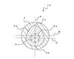
- Sectional drawing which shows the multi-core fiber 1b Sectional drawing which shows the state which hold
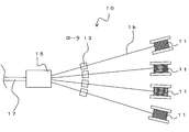
- the top view which shows the optical fiber tape core wire manufacturing apparatus 10.
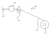
- FIG. The side view which shows the optical fiber tape cable manufacturing apparatus 10.
- FIG. Sectional drawing which shows the multi-core fiber 1b in the H section of FIG. Sectional drawing which shows the tape core wire 17.
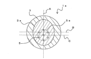
- FIG. 1 is a cross-sectional view of the multicore fiber 1 in a cross section perpendicular to the longitudinal direction of the multicore fiber 1 that is an optical fiber.
- the multi-core fiber 1 includes a plurality of cores 5, a clad 3 having a refractive index lower than that of the core 5 disposed on the outer periphery of the core 5, and a resin coating 7 that covers the clad 3.
- the plurality of cores 5 are arranged at a predetermined interval.
- the plurality of cores 5 are collectively referred to as a core group 5a.
- the core group 5a is composed of, for example, seven cores 5 in total, and the core 5 is disposed at each vertex of a regular hexagon around the center of the core group 5a and covered therewith. That is, the central core 5 and the surrounding six cores 5 are all at a constant interval, and the cores 5 are arranged to have symmetry within the core group 5a.
- the core 5 having symmetry in the core group 5a means that the arrangement of the cores 5 has an axis of symmetry.
- the core 5 serves as a signal light waveguide.
- the arrangement of the cores 5 is not limited to the illustrated example.
- a resin coating 7 is formed on the outer periphery of the cladding 3.
- the clad 3 and the resin coating 7 have a substantially circular cross section. Further, in the cross section perpendicular to the longitudinal direction of the multi-core fiber 1, the center positions of the clad 3 and the resin coating 7 are substantially the same.
- the position of the center of the multi-core fiber 1 (cladding 3) and the position of the center of the core group 5a are different.
- the center line of the multi-core fiber 1 (cladding 3) is A
- the center line perpendicular thereto is B
- the center line of the core group 5a is A
- the center line perpendicular thereto is C.
- the center line A is common
- the center line B and the center line C are shifted from each other.
- FIG. 1 shows an example in which the center line A is common, both may be shifted in a direction perpendicular to the center line A.
- the amount of deviation between the center position of the multi-core fiber 1 and the center position of the core group 5a is preferably larger than 1 ⁇ m, more preferably 2 ⁇ m or more from the viewpoint of identification.
- the amount of deviation is too large, there arises a problem that the outer diameter of the clad needs to be increased, so that the thickness is preferably 10 ⁇ m or less.
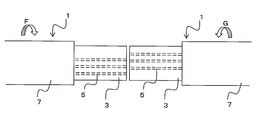
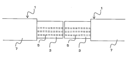
- FIG. 2A and FIG. 2B are diagrams showing the alignment process between the multi-core fibers 1.
- the resin coating 7 at the tip of each of the pair of multi-core fibers 1 to be connected is removed by a predetermined length (resin coating removing step).
- a pair of multi-core fibers 1 are arranged so as to face each other (fiber arrangement step).
- the position of the cladding 3 and the like is confirmed from a plurality of directions (for example, the D direction and the E direction in FIG. 1) perpendicular to the longitudinal direction of the multicore fiber 1.
- the positional deviation in the direction perpendicular to the longitudinal direction of the cladding 3 (the vertical direction in the figure and the direction perpendicular to the paper surface, hereinafter referred to as the X direction and the Y direction) can be adjusted by confirming the position of the outer shape. it can.
- the position in the rotation direction with the longitudinal direction of the multi-core fiber 1 as the rotation axis (hereinafter simply referred to as the rotation direction) is aligned.
- the rotation direction As described above, by confirming the clad 3 and the core 5 from a plurality of directions perpendicular to the longitudinal direction of the multi-core fiber 1, the position of the core 5 inside the clad 3 can be confirmed.
- the position of the core group 5a is decentered from the center of the clad 3, if the desired cores 5 are not positioned to face each other, the positions of the cores 5 are visually recognized as shifted.
- one or both of the multi-core fibers 1 are rotated with the longitudinal direction of the multi-core fiber 1 as the axis of rotation (arrow F, arrow G in the figure), and the core 5 Match the positions (alignment process).
- the alignment work between the multicore fibers 1 is completed.
- the ends of the multi-core fibers 1 are fusion-spliced to each other so that each of the multi-core fibers 1 whose outer shapes and core arrangements are substantially the same in a cross section perpendicular to the longitudinal direction of the multi-core fibers 1.
- the core group 5a is eccentric in the cross section of the clad 3 during the alignment work between the multi-core fibers 1, the erroneous cores 5 are not connected to each other. Further, since it is not necessary to arrange a marker for identifying the core at a position where the symmetry is broken, the structure is not complicated.
- the core 5 has a symmetrical arrangement, the layout design of the core 5 is easy, and connection with another optical fiber or optical element is also easy.
- the core group 5a is formed by arranging the plurality of cores 5 so as to have symmetry in the cross section perpendicular to the longitudinal direction of the multi-core fiber 1 has been described.
- the present invention is applicable as long as the shape of the cross section perpendicular to the longitudinal direction of 1 has directionality with respect to the rotational direction about the longitudinal direction of the multi-core fiber 1.
- the arrangement of the cores in the cross section has symmetry will be described unless otherwise specified, but it may be directional with respect to the rotation direction.
- FIG. 3 is a cross-sectional view showing a multi-core fiber 1a according to the second embodiment.
- components having the same functions as those of the multi-core fiber 1 and the like are denoted by the same reference numerals as those in FIG.
- the multi-core fiber 1a has substantially the same configuration as the multi-core fiber 1, but differs in that the cladding 3a is non-circular. More specifically, the clad 3a of the multicore fiber 1a is substantially elliptical.
- the multicore fiber 1a includes the center of the clad 3a of the multicore fiber 1a (intersection of the center line A in the major axis direction and the center line B in the minor axis direction) and the center of the core group 5a (center line A). And the intersection of the center line C) are shifted. That is, the core group 5a is arranged eccentrically with respect to the clad 3a.
- the eccentric direction of the core group 5a is preferably the long axis direction.
- the center line A in the major axis direction of the clad 3a and the center line A in the same direction of the core group 5a are common.
- the cross-sectional external shape of the resin coating 7 is a substantially perfect circle. Further, the center of the resin coating 7 and the center of the clad 3a substantially coincide.
- the resin coating 7 at each end of the pair of multi-core fibers 1a to be connected is removed by a predetermined length.
- the clad 3a is sandwiched between a pair of V-groove jigs 9a and 9b within a range where the resin coating 7 is removed.
- the V-groove jigs 9a and 9b are members each having a V-groove.
- V-groove jig is generally used for mechanical splices and the like.
- the major axis direction of the cross-section of the multi-core fiber 1a can be naturally restrained so as to be opposite to the V-groove jig. Therefore, it becomes easy to align so as to always be in a constant rotational direction.
- this mechanism is provided in the fiber holder of the fusion splicer, batch connection with multi-fiber tape is possible. This is because the rotation direction can be adjusted if the clad 3a with the resin coating 7 peeled is pressed by the V-groove if the multi-core tape is aligned to some extent.
- the rotation direction of the multi-core fiber 1a can be substantially aligned with the direction shown in the figure simply by sandwiching the clad 3a with the V-groove jigs 9a and 9b. it can.
- alignment can be easily performed.
- alignment may be performed by aligning the V-groove as a temporary alignment, and then rotating at least one of the multi-core fibers 1a so that the positions of the cores 5 coincide. As described above, by rotating at least one of the multi-core fibers 1a so that the positions of the cores 5 of the respective multi-core fibers 1a coincide with each other in the confirmation directions (D direction and E direction in FIG. 1) of the plurality of cores 5. Alignment can be performed.
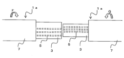
- the outer shape varies depending on the position of the multi-core fibers 1a in the rotational direction. Visible. Therefore, for example, by measuring the shape of the cladding 3a from the side surface of the multi-core fiber 1a with a plurality of external measuring instruments and rotating at least one multi-core fiber 1a so that the long axis and the short axis are aligned with each other, FIG. ), Alignment can be performed. Thereafter, it may be further confirmed that the positions of the cores 5 are matched. In this state, the ends of the multi-core fibers 1a are fusion-spliced so that the multi-core fibers can be connected to each other and a multi-core fiber connection structure can be obtained.
- the same effect as that of the first embodiment can be obtained.
- the clad 3a is non-circular (elliptical)
- alignment can be easily performed with a V-groove jig.
- alignment can be performed by checking the outer shape.
- the clad 3a has an elliptical shape, it can be expected that, for example, end portions in the major axis direction of the clad 3a are attracted to each other due to the surface tension of the molten glass. For this reason, there is a possibility that some displacement in the rotational direction is alleviated at the time of fusion.
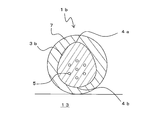
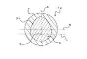
- FIG. 6 is a cross-sectional view illustrating a multi-core fiber 1b according to the third embodiment.
- the multi-core fiber 1b has substantially the same configuration as that of the multi-core fiber 1a, except that the clad 3b has a substantially drop shape. That is, the cladding 3b is also non-circular.
- the cross-sectional external shape of the resin coating 7 is a substantially perfect circle shape. Further, the center of the resin coating 7 and the center of the clad 3a substantially coincide.
- the drop shape is formed in an arc shape having a continuous entire circumference, and has a major axis and a minor axis perpendicular to the major axis, and is substantially line symmetric with the major axis as a symmetry axis.
- the radius of curvature of one arc portion on the long axis and the other arc portion facing the arc portion are different from each other.
- the upper arc portion on the center line A in the major axis direction is the small diameter portion 4a
- the lower arc portion is the large diameter portion 4b having a larger curvature radius than the small diameter portion 4a.
- the multicore fiber 1b includes the center of the clad 3b of the multicore fiber 1b (intersection of the center line A in the major axis direction and the center line B in the minor axis direction) and the center of the core group 5a (center line A). And the intersection of the center line C) are shifted.
- the center line B in the minor axis direction of the clad 3b is orthogonal to the center line A, and the length of the clad 3b in the major axis direction on the center line A (maximum length) is 1 / The center line passing through the position of 2.
- the core group 5a is arranged eccentrically with respect to the clad 3b.
- the eccentric direction of the core group 5a is preferably the long axis direction and the large diameter portion 4b side having a large curvature radius.
- the center line A in the major axis direction of the clad 3b and the center line in the same direction of the core group 5a are common.
- V-groove jigs 9a and 9b can be used as in the multi-core fiber 1a.
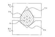
- the clad 3b is paired with a pair of V-grooves in the range where the resin coating 7 is removed as shown in FIG. It is sandwiched between jigs 9a and 9b.
- the V groove shape of the V groove jig 9a is a shape suitable for the large diameter portion 4b of the clad 3b
- the V groove shape of the V groove jig 9b is a shape suitable for the small diameter portion 4a of the clad 3b.
- the direction of the clad 3b can be naturally aligned.
- the rotation direction of the multi-core fiber 1b can be substantially aligned with the direction shown in the figure simply by sandwiching the clad 3b with the V groove jigs 9a and 9b. it can.
- alignment can be performed by making the multi-core fibers 1a sandwiched between the V-groove jigs 9a and 9b face each other.
- alignment may be performed by aligning the V-groove as a temporary alignment, and then rotating at least one of the multi-core fibers 1b so that the positions of the cores 5 coincide. As described above, by rotating at least one of the multi-core fibers 1b so that the positions of the cores 5 of the respective multi-core fibers 1b coincide with each other in the confirmation directions of the plurality of cores 5 (D direction and E direction in FIG. 1). Alignment can be performed.
- the outer shape of the clad 3b is measured in a state where the pair of multi-core fibers 1b are arranged so as to face each other without using a V-groove jig, and at least the long axis and the short axis are aligned with each other. Alignment can also be performed by rotating one multi-core fiber 1b. Thereafter, it may be further confirmed that the positions of the cores 5 are matched.
- V-groove jigs 9a and 9b can be taped with the respective rotational direction positions of the plurality of multicore fibers 1b aligned, but other methods can also be used. .
- FIG. 8 is a schematic plan view showing the optical fiber ribbon manufacturing apparatus 10
- FIG. 9 is a schematic side view showing the optical fiber ribbon manufacturing apparatus 10.
- the optical fiber ribbon manufacturing apparatus 10 includes a roller 13, a tape resin coating portion 15, and the like.
- an example in which four multicore fibers 1b are taped is shown, but the number of multicore fibers 1b is not limited.
- the multi-core fibers 1b fed out from the bobbin 11 are respectively sent to the rollers 13.
- the multi-core fiber 1b is bent in contact with the roller 13 in a state where a predetermined tension is applied.
- FIG. 10 is a partial cross-sectional view taken along a portion H in FIG.
- the multi-core fiber 1b when the multi-core fiber 1b is brought into contact with the roller 13 and bent in a state where a predetermined tension is applied, the multi-core fiber 1b rotates by itself so as to be in a more stable rotation direction. . Specifically, the multi-core fiber 1b rotates so that the center of gravity position (large diameter portion 4b) of the clad 3b is on the roller 13 side (inner peripheral side of the bent portion).
- the large-diameter portion 4b side is lighter and less stretchable than the small-diameter portion 4a side, and therefore the deformable small-diameter portion 4a faces the outer peripheral side and is deformed close to the center of gravity. This seems to be because the large-diameter portion 4 b that is difficult to press is pressed against the roller 13.
- the cross-section of the multi-core fiber 1b is taken along the center line of the resin coating 7 perpendicular to the major axis of the cladding 3b (ie, the center line B in FIG. 6).
- the proportion of the clad 3b in each region of the cross section of the multi-core fiber 1b is compared, and the proportion of the clad 3b is larger on the large-diameter portion 4b side than on the small-diameter portion 4a side.
- the ratio of the resin coating 7 is larger on the small diameter portion 4a side than on the diameter portion 4b side.
- the large diameter portion 4b side rotates in a direction in which it is pressed against the roller 13 side.
- each multi-core fiber 1b is aligned in a more stable direction by contact with the roller 13, and the multi-core fibers 1b all aligned in a certain direction pass through the tape resin coating portion 15.
- the tape resin coating portion 15 is an extruder composed of, for example, an alignment die or an extrusion die.
- the tape resin coating applied at the tape resin coating portion 15 is cured by drying or UV irradiation as necessary.
- the tape core wire 17 in which a plurality of multi-core fibers 1b are integrated is wound up by a winding device (not shown). Thus, the tape core wire 17 is manufactured.
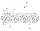
- FIG. 11 is a cross-sectional view of the tape core wire 17.
- the tape core wire 17 is formed by providing a plurality of multi-core fibers 1b and coating the outer periphery with the tape resin coating 19 so as to be integrated.
- the clads 3 b of all the multicore fibers 1 b are arranged so as to face in the same direction. More specifically, the large-diameter portion 4b of the clad 3b is arranged so as to align with the same surface direction of the tape core wire 17.
- the multi-core fibers 1b are arranged so that the cores 5 of all the multi-core fibers 1b are arranged in the same direction.
- the multi-core fiber 1 is disposed so that one center line of each of the multi-core fibers 1 connecting the three cores 5 is all directed in the thickness direction (vertical direction in the figure) of the tape core wire 17.
- the arrangement of the cores 5 is substantially constant over the entire length of the tape core wire 17 in the longitudinal direction. That is, the arrangement of the cores 5 is always substantially constant in any cross section in the longitudinal direction of the tape core wire 17.
- the same effect as in the second embodiment can be obtained. Further, since the clad 3b has a drop shape, the optical fiber tape core manufacturing apparatus 10 can easily manufacture the tape core other than the alignment method similar to that of the clad 3a.
- the self-rotation force of the multi-core fiber 1b is used. For this reason, it is necessary to provide a sufficient distance between the bobbin 11 and the roller 13 (if there is another configuration, between the other configuration and the roller 13). This is because if the distance is short, the rotation of the multi-core fiber 1b is restricted by the bobbin 11 or the like, and free rotation may be hindered.
- the multi-core fiber applicable to the present invention is not limited to the above-described form.
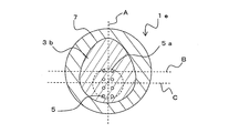
- the present invention can also be applied to a multi-core fiber 1d in which cores 5 are arranged in a row.
- the cores 5 are arranged in two rows is shown.
- the minimum circle including the core 5 may be the core group 5a, and the center may be arranged so as to be shifted from the center of the clad 3.
- such an arrangement of the core 5 may be combined with the elliptical clad 3a.
- such an arrangement of the cores 5 may be combined with a drop-shaped clad 3b.
- FIG. 13 is a cross-sectional view of a tape core wire 17a using the multicore fiber 1 as an example.
- the tape core wire 17a is manufactured by observing the position of the core 5 by side observation of the end face of the multi-core fiber 1 and providing a coating resin on the outer periphery while aligning the directions of all the multi-core fibers 1 to form a tape. The By doing in this way, in the cross section perpendicular
- optical fiber embodiments The present invention can also be applied to an optical fiber having a single core 5.
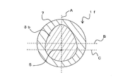
- an optical fiber 1f shown in FIG. 14A includes a single core 5, a clad 3b that covers the core 5, and a resin coating 7 that covers the clad 3b.
- the cross-sectional shape of the cladding 3b in a cross section perpendicular to the longitudinal direction of the optical fiber 1f is a non-true circle (an example of a drop shape is shown in the figure).
- the position of the core 5 (intersection of the center line A and the line C) is arranged at a position shifted from the center position of the clad 3b (intersection of the center lines A and B). Therefore, the shape of the cross section perpendicular to the longitudinal direction of the optical fiber 1f is directional with respect to the rotation direction about the longitudinal direction of the optical fiber 1f.
- the cross-sectional shape of the clad 3b is non-circular, the cross-section of the optical fiber 1f is suppressed by using the V-groove jigs 9a and 9b shown in FIG. Can be naturally restrained so that the major axis direction of this is the opposite direction of the V-groove jig. Therefore, it becomes easy to align so as to always be in a constant rotational direction.
- aligning a pair of optical fibers 1f at least one of the optical fibers 1f is aligned so that the positions of the cores 5 coincide with each other in the confirmation direction of the core 5 (D direction and E direction in FIG. 1). By rotating the fiber 1f, the pair of optical fibers 1f can be aligned.
- the outer shape is visually recognized to be different depending on the position of the optical fiber 1f in the rotation direction. Therefore, for example, the shape of the clad 3b is measured from the side surface of the optical fiber 1f with a plurality of outer shape measuring instruments, and alignment is performed by rotating at least one of the optical fibers 1f so that the major axis and the minor axis are aligned with each other. be able to.
- the resin coating 7 at the tip of each of the pair of optical fibers 1f to be connected is removed by a predetermined length (resin coating removing step), and the pair of optical fibers 1f are arranged to face each other (fiber Placement step), the pair of optical fibers are sandwiched and held by a pair of V-groove jigs, respectively, and the optical fibers 1f are reliably aligned by aligning the rotation direction of the optical fibers (alignment step). It can be performed.
- the optical fibers 1f having substantially the same outer shape and core arrangement of the optical fibers, and the cores 5 and the clad 3b.
- a connection structure of a pair of optical fibers can be obtained by fusing together.
- FIG. 14B is a diagram showing an optical fiber 1g in which a marker 6 is arranged separately from the core 5 with respect to the optical fiber 1f.
- the marker 6 may be arranged at a position that is easier to confirm than the core 5 from the side of the clad 3 b separately from the core 5.
- alignment is performed by rotating at least one of the optical fibers 1g so that the positions of the markers 6 of the respective optical fibers 1g coincide in the confirmation direction of the marker 6 (D direction and E direction in FIG. 1). Can be taped and connected.
- the optical fiber tape core manufacturing apparatus 10 shown in FIG. 8 and FIG. It is also possible to produce a 1 g tape core. That is, a tape core wire can be manufactured from a bending step of bending each optical fiber 1f, 1g along a roller and a tape forming step of forming the optical fibers 1f, 1g into a tape. Thus, a plurality of optical fibers 1f and 1g are provided side by side, and a tape core wire whose outer periphery is coated with a tape resin coating can be obtained. At this time, in the cross section perpendicular to the longitudinal direction of the tape core wire, the clads 3b of all the optical fibers 1f and 1g can be arranged so as to face in the same direction.
- the cross-sectional shape of the non-circular clad may be other than an elliptical shape or a drop shape.
Landscapes
- Physics & Mathematics (AREA)
- General Physics & Mathematics (AREA)
- Optics & Photonics (AREA)
- Engineering & Computer Science (AREA)
- Plasma & Fusion (AREA)
- Mechanical Coupling Of Light Guides (AREA)
- Optical Couplings Of Light Guides (AREA)
Abstract
マルチコアファイバ1は、複数のコア5と、コア5の周囲を被覆し、コア5よりも屈折率が低いクラッド3と、クラッド3を被覆する被覆樹脂7とからなる。複数のコア5をまとめて、コア群5aとする。コア群5aの範囲内において、コア5は対称性を有するように配置される。マルチコアファイバ1の長手方向と垂直な断面において、クラッド3と樹脂被覆の中心位置は略一致する。一方、マルチコアファイバ1の長手方向と垂直な断面において、マルチコアファイバの中心の位置と、コア群5aの中心の位置はずれている。
Description
本発明は、光ファイバ同士の接続時における調芯作業が容易な光ファイバ等に関するものである。
近年の光通信におけるトラフィックの急増により、一般的に用いられているシングルコアの光ファイバにおいて伝送容量の限界が近づいている。そこで、さらに通信容量を拡大する手段として、一本の光ファイバに複数のコアが形成されたマルチコアファイバが提案されている。マルチコアファイバを用いることで、光ファイバの敷設コストを抑え、伝送容量の拡大が可能となる。
マルチコアファイバが伝送路として用いられた場合、このマルチコアファイバの各コアは、それぞれ別の光ファイバや光素子等と接続されて伝送信号を送受する必要がある。別の光ファイバや光素子等と接続にあたっては、マルチコアファイバを調芯する必要がある。しかし、マルチコアファイバは、断面の中心以外にもコアが配置されているため、シングルコアの光ファイバと比較して調芯が難しいという問題がある。
このようなマルチコアファイバの調芯作業を容易にする方法としては、例えば、コアとは別にマーカを配置する方法がある(例えば特許文献1)。
また、マルチコアファイバ以外であっても、光ファイバの長手方向に対して垂直な断面形態が前記光ファイバの長手方向を軸とする回転方向に対して方向性を有する光ファイバは、マルチコアファイバと同様に中心に1つだけコアを有する一般的なシングルコアの光ファイバと比較して調芯が難しいという問題がある。
また、マルチコアファイバ以外であっても、光ファイバの長手方向に対して垂直な断面形態が前記光ファイバの長手方向を軸とする回転方向に対して方向性を有する光ファイバは、マルチコアファイバと同様に中心に1つだけコアを有する一般的なシングルコアの光ファイバと比較して調芯が難しいという問題がある。
このような、光ファイバの長手方向に対して垂直な断面において、コアの配置が光ファイバの長手方向を軸とする回転方向に対して方向性を有する光ファイバの調芯作業を容易にする方法が望まれている。
本発明は、このような問題に鑑みてなされたもので、調芯作業が容易な光ファイバ等を提供することを目的とする。
前述した目的を達成するため、第1の発明は、複数のコアからなるコア群と、前記コア群を被覆するクラッドと、前記クラッドを被覆する樹脂被覆と、を有する光ファイバであって、前記光ファイバの長手方向に対して垂直な断面の形態が、前記光ファイバの長手方向を軸とする回転方向に対して方向性を有し、かつ、前記クラッドの中心の位置と、前記コア群の中心の位置が異なることを特徴とする光ファイバである。
前記光ファイバの長手方向に対して垂直な断面において、複数の前記コアが対称性を有するように配置されて前記コア群が形成されることが望ましい。
前記光ファイバの長手方向に対して垂直な断面における前記クラッドの断面形状が、非真円形であることが望ましい。
前記光ファイバの長手方向に対して垂直な断面における前記クラッドの断面形状が楕円形であってもよい。
前記光ファイバの長手方向に対して垂直な断面における前記クラッドの断面形状がしずく形であってもよい。
第1の発明によれば、光ファイバの長手方向に垂直な断面において、クラッドの中心の位置と、コア群の中心の位置が異なるため、特定のコアの位置を識別可能である。また、コア群を構成するコアが対称性を有する配置となっていれば、構造が簡易であり、別の光ファイバや光素子等と接続も容易である。
また、クラッドの断面形状が非真円形であれば、調芯時において、外形によってもコアのおおよその位置を特定することができるため、調芯が容易である。この場合、クラッドの断面形状を楕円形やしずく形とすることで、V溝治具等を利用して、光ファイバの回転方向の向きを規制することができる。
第2の発明は、コアと、前記コアを被覆するクラッドと、前記クラッドを被覆する樹脂被覆と、を有する光ファイバであって、前記光ファイバの長手方向に対して垂直な断面における前記クラッドの断面形状が、非真円形であり、前記光ファイバの長手方向に対して垂直な断面の形態が、前記光ファイバの長手方向を軸とする回転方向に対して方向性を有し、かつ、前記クラッドの中心の位置と、前記コアの中心の位置が異なることを特徴とする光ファイバである。
第2の発明によれば、光ファイバの長手方向に垂直な断面において、クラッドの中心の位置と、コアの位置が異なるような、単心の光ファイバであっても、クラッドの断面形状が非真円形であるため、調芯時において、外形によってコアの位置を特定することができるため、調芯が容易である。
第3の発明は、第1の発明にかかる光ファイバを複数本併設し、その外周をテープ樹脂被覆により被覆したテープ心線であって、前記テープ心線の長手方向に垂直な断面において、全ての前記光ファイバの前記クラッドが同一の方向に向くように配置されていることを特徴とするテープ心線である。
第4の発明は、第2の発明にかかる光ファイバを複数本併設し、その外周をテープ樹脂被覆により被覆したテープ心線であって、前記テープ心線の長手方向に垂直な断面において、全ての前記光ファイバの前記クラッドが同一の方向に向くように配置されていることを特徴とするテープ心線である。
第3、第4の発明によれば、長手方向のいずれの位置においても、全ての光ファイバの向きがそろっているため、別の光ファイバや光素子等と接続も容易である。
第5の発明は、複数のコアからなるコア群と、前記コア群を被覆するクラッドと、前記クラッドを被覆する樹脂被覆と、を有する一対の光ファイバの調芯方法であって、前記光ファイバの長手方向に対して垂直な断面の形態が、前記光ファイバの長手方向を軸とする回転方向に対して方向性を有し、かつ、前記クラッドの中心の位置と、前記コア群の中心の位置が異なっており、一対の前記光ファイバの先端の前記樹脂被覆を所定長さ除去する樹脂被覆除去工程と、一対の前記光ファイバを対向するように配置するファイバ配置工程と、前記光ファイバの長手方向に対して垂直な複数方向から、前記クラッドにおける前記コアの位置を確認し、それぞれの前記光ファイバの前記コアの位置が一致するように、一方または両方の前記光ファイバを回転させる調芯工程と、を具備することを特徴とする光ファイバの調芯方法である。
第5の発明によれば、光ファイバの長手方向に垂直な断面において、コア群がクラッドに対して偏心しているため、誤った向きで光ファイバ同士を接続することを防止することができる。
第6の発明は、複数のコアからなるコアと、前記コアを被覆するクラッドと、前記クラッドを被覆する樹脂被覆と、を有する複数の光ファイバを用いたテープ心線の製造方法であって、前記光ファイバの長手方向に対して垂直な断面の形態が、前記光ファイバの長手方向を軸とする回転方向に対して方向性を有し、かつ、前記クラッドの中心の位置と、前記コア群の中心の位置が異なっており、前記クラッドの断面形状がしずく形であり、それぞれの前記光ファイバをローラに沿って屈曲させる屈曲工程と、前記光ファイバをテープ化するテープ化工程と、を具備することを特徴とするテープ心線の製造方法である。
第6の発明によれば、ローラに対して所定の張力で光ファイバを接触させると、しずく形クラッドの重心の偏心方向がローラの接触部に近い側に向くことを利用して、容易に光ファイバの向きを揃えて、テープ心線を製造することができる。
第7の発明は、複数のコアからなるコア群と、前記コア群を被覆するクラッドと、前記クラッドを被覆する樹脂被覆と、を有する一対の光ファイバの接続構造であって、前記光ファイバの長手方向に対して垂直な断面の形態が、前記光ファイバの長手方向を軸とする回転方向に対して方向性を有し、かつ、前記クラッドの中心の位置と、前記コア群の中心の位置が異なっており、前記光ファイバの長手方向に対して垂直な断面において、一対の前記光ファイバの外形および前記コアの配置が、ほぼ同じであり、それぞれのコア同士およびクラッド同士が接続されていることを特徴とする光ファイバの接続構造である。
第7の発明によれば、光ファイバの長手方向に垂直な断面において、コア群またはコアがクラッドに対して偏心している光ファイバ同士の接続構造を得ることができる。
本発明によれば、調芯作業が容易な光ファイバ等を提供することができる。
(第1実施形態)
以下、本発明にかかる光ファイバについて説明する。図1は光ファイバであるマルチコアファイバ1の長手方向と垂直な断面におけるマルチコアファイバ1の断面図である。
以下、本発明にかかる光ファイバについて説明する。図1は光ファイバであるマルチコアファイバ1の長手方向と垂直な断面におけるマルチコアファイバ1の断面図である。
マルチコアファイバ1は、複数のコア5と、コア5の外周に配置されたコア5よりも屈折率が低いクラッド3と、クラッド3を被覆する樹脂被覆7とからなる。複数のコア5は所定の間隔で配置される。ここで、本発明では、複数のコア5をまとめて、コア群5aとする。コア群5aは、例えば、全部で7つのコア5からなり、コア5は、コア群5aの中心と、その周囲に正六角形の各頂点位置に配置され、クラッド3で被覆される。すなわち、中心のコア5と周囲の6つのコア5とは全て一定の間隔となり、コア群5aの範囲内において、コア5は対称性を有するように配置される。
ここで、コア群5aにおいてコア5が対称性を有するとは、コア5の配置が対称軸を有することとする。コア5は、信号光の導波路となる。なお、コア5の配置は、図示した例には限られない。
クラッド3の外周には、樹脂被覆7が形成される。クラッド3および樹脂被覆7は、断面が略真円形状である。また、マルチコアファイバ1の長手方向と垂直な断面において、クラッド3と樹脂被覆7の中心位置は略一致する。
一方、マルチコアファイバ1の長手方向と垂直な断面において、マルチコアファイバ1(クラッド3)の中心の位置と、コア群5aの中心の位置は異なっている。ここで、マルチコアファイバ1(クラッド3)の中心線をAとし、これと垂直な中心線をBとする。また、同様に、コア群5aの中心線をA、これと垂直な中心線をCとする。図に示した例では、中心線Aが共通し、中心線Bと中心線Cがずれた位置となる。なお、図1は、中心線Aが共通する例を示したが、中心線Aと垂直な方向にも、両者がずれていてもよい。
また、マルチコアファイバ1の中心の位置と、コア群5aの中心の位置のずれ量は、識別の観点から1μmより大きいことが好ましく、より好ましくは2μm以上である。ただし、ずれ量が大きすぎるとクラッド外径を大きくする必要があるなどの問題が生じるため、10μm以下であることが好ましい。
マルチコアファイバ1の長手方向に対して垂直な断面の形態は、マルチコアファイバ1の長手方向を軸とする回転方向に対して方向性を有する。そこで、次に、マルチコアファイバ1を接続する際の調芯方法について説明する。図2(a)、図2(b)は、マルチコアファイバ1同士の調芯工程を示す図である。まず、接続対象である一対のマルチコアファイバ1のそれぞれの先端の樹脂被覆7を所定長さ除去する(樹脂被覆除去工程)。次に、図2(a)に示すように、一対のマルチコアファイバ1を対向するように配置する(ファイバ配置工程)。
この状態で、クラッド3の側方から、コア5の位置を確認する。より具体的には、まず、マルチコアファイバ1の長手方向に対して垂直な複数方向(例えば、図1のD方向およびE方向)から、クラッド3等の位置を確認する。クラッド3の長手方向に垂直な方向(図の上下方向および紙面に垂直な方向。以下、X方向およびY方向とする。)の位置ずれは、外形の位置を確認することで、調整することができる。
X方向、Y方向の調芯が完了すると、マルチコアファイバ1の長手方向を回転軸とした回転方向の位置(以下、単に回転方向とする)を調芯する。前述した様に、マルチコアファイバ1の長手方向に対して垂直な複数方向からクラッド3、コア5を確認することで、クラッド3内部のコア5の位置を確認することができる。本発明では、コア群5aの位置が、クラッド3の中心から偏心しているため、所望のコア5同士が対向する位置にないと、コア5の位置がずれて視認される。
次に、図2(b)に示すように、それぞれのマルチコアファイバ1の一方または両方を、マルチコアファイバ1の長手方向を回転軸として回転させて(図中矢印F、矢印G)、コア5の位置を一致させる(調芯工程)。いずれのコア5の確認方向(図1のD方向およびE方向)においても、それぞれのマルチコアファイバ1のコア5の位置が一致すると、マルチコアファイバ1同士の調芯作業が完了する。この状態で、マルチコアファイバ1同士の先端を融着接続することで、マルチコアファイバ1の長手方向に対して垂直な断面において、互いの外形およびコアの配置がほぼ同じであるマルチコアファイバ1同士のそれぞれのコア同士およびクラッド同士が接続され、一対のマルチコアファイバの接続構造を得ることができる。
以上、本実施の形態によれば、マルチコアファイバ1同士の調芯作業の際、コア群5aがクラッド3の断面において偏心しているため、誤ったコア5同士を接続してしまうことがない。また、対称性を壊す位置にコア識別のためのマーカ等を配置する必要がないため、構造が複雑化しない。
また、コア5が対称性を有する配置であるため、コア5のレイアウト設計が容易である上、別の光ファイバや光素子等と接続も容易である。
なお、以上の説明では、マルチコアファイバ1の長手方向に対して垂直な断面において、複数のコア5が対称性を有するように配置されてコア群5aが形成される例について説明したが、マルチコアファイバ1の長手方向に対して垂直な断面の形態が、マルチコアファイバ1の長手方向を軸とする回転方向に対して方向性を有するものであれば、本発明は適用可能である。以下の説明では、特に記載がない限り、断面のコアの配置が対称性を有する場合について説明するが、回転方向に対して方向性を有するものであってもよい。
(第2実施形態)
次に、第2の実施形態について説明する。図3は、第2の実施の形態にかかるマルチコアファイバ1aを示す断面図である。なお、以下の説明において、マルチコアファイバ1等と同様の機能を奏する構成については、図1等と同一の符号を付して、重複する説明を省略する。
次に、第2の実施形態について説明する。図3は、第2の実施の形態にかかるマルチコアファイバ1aを示す断面図である。なお、以下の説明において、マルチコアファイバ1等と同様の機能を奏する構成については、図1等と同一の符号を付して、重複する説明を省略する。
マルチコアファイバ1aは、マルチコアファイバ1とほぼ同様の構成であるが、クラッド3aが非真円形である点で異なる。より具体的には、マルチコアファイバ1aのクラッド3aは略楕円形である。
マルチコアファイバ1aは、マルチコアファイバ1と同様に、マルチコアファイバ1aのクラッド3aの中心(長軸方向の中心線Aと短軸方向の中心線Bの交点)と、コア群5aの中心(中心線Aと中心線Cの交点)がずれている。すなわち、コア群5aは、クラッド3aに対して偏心して配置される。なお、コア群5aの偏心方向は、長軸方向であることが望ましい。この場合、クラッド3aの長軸方向の中心線Aとコア群5aの同一方向の中心線Aとが共通する。なお、樹脂被覆7の断面外形は略真円である。また、樹脂被覆7の中心とクラッド3aの中心は略一致する。
マルチコアファイバ1aの調芯を行う場合には、マルチコアファイバ1と同様に、まず、接続対象である一対のマルチコアファイバ1aのそれぞれの先端の樹脂被覆7を所定長さ除去する。
次に、図4に示すように、樹脂被覆7を除去した範囲において、クラッド3aを一対のV溝治具9a、9bで挟み込む。V溝治具9a、9bは、それぞれV溝が形成された部材である。
なお、このようなV溝治具は、メカニカルスプライスなどで一般に使用されている。適切な形状のV溝で抑え込むと、マルチコアファイバ1aの断面の長軸方向がV溝治具の対向方向になるように自然と抑え込むことができる。従って、常に一定の回転方向にそろうように整列することが容易になる。例えば、融着機のファイバホルダーにこの機構を設ければ、多心テープで一括接続も可能になる。多心テープである程度の整列がされていれば、樹脂被覆7を剥いだ状態のクラッド3aをV溝で押さえ込めば、回転方向が合わせられるためである。
このように、V溝の形状をクラッド3aに対応させることで、クラッド3aをV溝治具9a、9bで挟み込むだけで、マルチコアファイバ1aの回転方向の向きを、概ね図示した方向に揃えることができる。このような、V溝治具9a、9bで挟み込まれたマルチコアファイバ1a同士を対向させることで、調芯を容易に行うことができる。
なお、V溝での調芯を仮調芯として、その後、それぞれのマルチコアファイバ1aの少なくとも一方を回転させて、コア5の位置を一致させることで、調芯を行ってもよい。前述した様に、複数のコア5の確認方向(図1のD方向およびE方向)において、それぞれのマルチコアファイバ1aのコア5の位置が一致するように少なくとも一方のマルチコアファイバ1aを回転させることで調芯を行うことができる。
また、図5(a)に示すように、V溝治具を用いなくても、一対のマルチコアファイバ1aを対向するように配置すると、マルチコアファイバ1aの回転方向の位置によって、外形が異なるように視認される。したがって、例えば、マルチコアファイバ1aの側面から複数の外形計測器でクラッド3aの形を計測し、互いの長軸と短軸を合わせるよう少なくとも一方のマルチコアファイバ1aを回転させることで、図5(b)に示すように、調芯を行うことができる。その後さらに、コア5の位置が一致していることを確認してもよい。この状態で、マルチコアファイバ1a同士の先端を融着接続することで、マルチコアファイバ同士を接続し、マルチコアファイバの接続構造を得ることができる。
第2の実施形態によれば、第1の実施形態と同様の効果を得ることができる。また、クラッド3aが非真円形(楕円形)であるため、V溝治具によって、容易に調芯を行うことができる。また、外形を確認することで、調芯を行うこともできる。
また、楕円形同士のクラッド3aを有するため、融着の際、溶融したガラスの表面張力によって、例えばクラッド3aの長軸方向の端部同士が引き寄せあうことが期待できる。このため、多少の回転方向の位置ずれが、融着時に緩和される可能性もある。
(第3実施形態)
次に、第3の実施形態について説明する。図6は、第3の実施の形態にかかるマルチコアファイバ1bを示す断面図である。マルチコアファイバ1bは、マルチコアファイバ1aとほぼ同様の構成であるが、クラッド3bが略しずく形である点が異なる。すなわち、クラッド3bも非真円形である。なお、樹脂被覆7の断面外形は略真円形状である。また、樹脂被覆7の中心とクラッド3aの中心は略一致する。
次に、第3の実施形態について説明する。図6は、第3の実施の形態にかかるマルチコアファイバ1bを示す断面図である。マルチコアファイバ1bは、マルチコアファイバ1aとほぼ同様の構成であるが、クラッド3bが略しずく形である点が異なる。すなわち、クラッド3bも非真円形である。なお、樹脂被覆7の断面外形は略真円形状である。また、樹脂被覆7の中心とクラッド3aの中心は略一致する。
ここで、しずく形とは、全周が連続した円弧状に形成されており、楕円と同様に、長軸およびこれと直交する短軸とを有し、長軸を対称軸として略線対称な形状であるとともに、長軸上の一方の円弧部とこれと対向する他方の円弧部の曲率半径が互いに異なる形状である。図示した例では、長軸方向の中心線A上の上方の円弧部が小径部4aであり、下方の円弧部が小径部4aよりも曲率半径の大きな大径部4bとなる。
マルチコアファイバ1bは、マルチコアファイバ1と同様に、マルチコアファイバ1bのクラッド3bの中心(長軸方向の中心線Aと短軸方向の中心線Bの交点)と、コア群5aの中心(中心線Aと中心線Cの交点)がずれている。ここで、クラッド3bの短軸方向の中心線Bは、中心線Aと直交し、中心線A上の長軸方向のクラッド3bの長さ(最大長さ)に対し、端部からその1/2となる位置を通る中心線をいう。
このように、コア群5aは、クラッド3bに対して偏心して配置される。なお、コア群5aの偏心方向は、長軸方向であって、曲率半径の大きな大径部4b側であることが望ましい。この場合、クラッド3bの長軸方向の中心線Aとコア群5aの同一方向の中心線とが共通する。
マルチコアファイバ1bの調芯を行う場合には、マルチコアファイバ1aと同様に、V溝治具9a、9bを用いることができる。まず、接続対象である一対のマルチコアファイバ1bのそれぞれの先端の樹脂被覆7を所定長さ除去した後、図7に示すように、樹脂被覆7を除去した範囲において、クラッド3bを一対のV溝治具9a、9bで挟み込む。
なお、適切な形状のV溝で抑え込むと、マルチコアファイバ1bの断面の長軸方向がV溝治具の対向方向になるように自然と抑え込むことができる。特に、V溝治具9aのV溝形状を、クラッド3bの大径部4bに適した形状とし、V溝治具9bのV溝形状を、クラッド3bの小径部4aに適した形状とすれば、クラッド3bの向きを自然とそろえることもできる。
このように、V溝の形状をクラッド3bに対応させることで、クラッド3bをV溝治具9a、9bで挟み込むだけで、マルチコアファイバ1bの回転方向の向きを、概ね図示した方向に揃えることができる。このようにして、V溝治具9a、9bで挟み込まれたマルチコアファイバ1a同士を対向させることで、調芯を行うことができる。
なお、V溝での調芯を仮調芯として、その後、それぞれのマルチコアファイバ1bの少なくとも一方を回転させて、コア5の位置を一致させることで、調芯を行ってもよい。前述した様に、複数のコア5の確認方向(図1のD方向およびE方向)において、それぞれのマルチコアファイバ1bのコア5の位置が一致するように少なくとも一方のマルチコアファイバ1bを回転させることで調芯を行うことができる。
また、前述した様に、V溝治具を用いなくても、一対のマルチコアファイバ1bを対向するように配置した状態でクラッド3bの外形を計測し、互いの長軸と短軸を合わせるよう少なくとも一方のマルチコアファイバ1bを回転させることで、調芯を行うこともできる。その後さらに、コア5の位置が一致していることを確認してもよい。
次に、マルチコアファイバ1bを用いたテープ心線の製造方法について説明する。前述したマルチコアファイバ1aと同様に、V溝治具9a、9bによって、複数のマルチコアファイバ1bのそれぞれの回転方向位置を揃えた状態でテープ化することもできるが、他の方法を用いることもできる。
図8は、光ファイバテープ心線製造装置10を示す概略平面図、図9は、光ファイバテープ心線製造装置10を示す概略側方図である。光ファイバテープ心線製造装置10は、ローラ13、テープ樹脂被覆部15等からなる。なお、図示した例では、4本のマルチコアファイバ1bをテープ化する例を示すが、マルチコアファイバ1bの本数は問わない。
ボビン11から繰り出されたマルチコアファイバ1bは、それぞれローラ13に送られる。マルチコアファイバ1bは、所定の張力が付与された状態でローラ13に接して屈曲する。
図10は、図9のH部における部分断面図である。図10に示すように、所定の張力を付した状態でマルチコアファイバ1bをローラ13に接触させて屈曲させると、マルチコアファイバ1bは、より安定な回転方向の向きとなるように、自身で回転する。具体的には、クラッド3bの重心位置(大径部4b)が、ローラ13側(屈曲部の内周側)にくるように、マルチコアファイバ1bが回転する。これは、大径部4b側は、小径部4a側と比較して、軽量で伸びやすい樹脂被覆7の量が少ないため、変形のしやすい小径部4aが外周側に向き、重心に近く変形のしにくい大径部4bがローラ13に押し付けられるようになるためと思われる。
より具体的には、マルチコアファイバ1bの長手方向に垂直な断面において、クラッド3bの長軸と直交する樹脂被覆7の中心線(すなわち、図6の中心線B)でマルチコアファイバ1bの断面を二つの領域に区分した場合、マルチコアファイバ1bの断面のそれぞれの領域におけるクラッド3bが占める割合を比較すると、小径部4a側よりも大径部4b側の方が、クラッド3bの占める割合が多く、大径部4b側よりも小径部4a側の方が、樹脂被覆7の占める割合が多い。ここで、マルチコアファイバ1bの断面における任意の中心線で領域を区分した場合において、最もクラッド3bの割合が多くなる方向が、ローラ13側となる方向に安定しやすい。したがって、大径部4b側がローラ13側に押し付けられる方向に回転する。
このように、それぞれのマルチコアファイバ1bがローラ13との接触によって、より安定な向きに揃えられ、すべて一定の向きに揃ったマルチコアファイバ1bは、テープ樹脂被覆部15を通過する。テープ樹脂被覆部15では、複数本のマルチコアファイバ1bが整列されて、外周部にテープ樹脂被覆が塗布される。テープ樹脂被覆部15は、例えば、整列ダイスや押出ダイスからなる押出機である。
テープ樹脂被覆部15で塗布されたテープ樹脂被覆は、必要に応じて、乾燥やUV照射によって硬化する。複数本のマルチコアファイバ1bが一体化されたテープ心線17は、図示を省略した巻き取り装置によって巻き取られる。以上により、テープ心線17が製造される。
図11は、テープ心線17の断面図である。前述した様に、テープ心線17は、複数のマルチコアファイバ1bが併設されて、その外周をテープ樹脂被覆19で被覆して一体化されたものである。テープ心線17の長手方向に垂直な断面において、全てのマルチコアファイバ1bのクラッド3bが同一の方向に向くように配置される。より具体的には、クラッド3bの大径部4bが、テープ心線17の同一の面方向に揃うように配置される。
この結果、全てのマルチコアファイバ1bのコア5の配置が、全て同じ向きに配列するようにマルチコアファイバ1bが配置される。例えば、図示した例では、3つのコア5をつなぐそれぞれのマルチコアファイバ1の一つの中心線が、全て、テープ心線17の厚み方向(図の上下方向)に向くようにマルチコアファイバ1が配置される。また、テープ心線17は、テープ心線17の長手方向の全長にわたって、コア5の配列が略一定である。すなわち、テープ心線17の長手方向の任意の断面において、常に、コア5の配列が略一定となる。
第3の実施形態によれば、第2の実施形態と同様の効果を得ることができる。また、クラッド3bがしずく形であるため、クラッド3aと同様の調芯方法以外に、光ファイバテープ心線製造装置10によって、容易にテープ心線を製造することができる。
なお、光ファイバテープ心線製造装置10においては、マルチコアファイバ1bの自己の回転力を利用する。このため、ボビン11とローラ13との間(他の構成がある場合には、他の構成とローラ13との間)の距離を十分にとる必要がある。この距離が短いと、マルチコアファイバ1bの回転がボビン11等によって拘束されて、自由な回転が阻害される恐れがあるためである。
(他のマルチコアファイバの実施形態)
本発明に適用可能なマルチコアファイバは、前述したような形態には限られない。例えば、図12(a)に示すように、コア5が列をなして配列したマルチコアファイバ1dにも適用が可能である。図示した例では、コア5が2列に配列した例を示す。この場合でも、コア5を包含する最小円をコア群5aとし、この中心がクラッド3の中心とずれるように配置すればよい。
本発明に適用可能なマルチコアファイバは、前述したような形態には限られない。例えば、図12(a)に示すように、コア5が列をなして配列したマルチコアファイバ1dにも適用が可能である。図示した例では、コア5が2列に配列した例を示す。この場合でも、コア5を包含する最小円をコア群5aとし、この中心がクラッド3の中心とずれるように配置すればよい。
また、図12(b)に示すマルチコアファイバ1dのように、このようなコア5の配置を、楕円形のクラッド3aと組み合わせてもよい。また、図12(c)に示すマルチコアファイバ1eのように、このようなコア5の配置を、しずく形のクラッド3bと組み合わせてもよい。
また、本発明は、マルチコアファイバ1b以外の他のマルチコアファイバについても、テープ心線とすることができる。図13は、一例としてマルチコアファイバ1を用いたテープ心線17aの断面図である。テープ心線17aは、マルチコアファイバ1の端面の側方観察で、コア5の位置を観察し、全てのマルチコアファイバ1の方向を合わせながら、外周に被覆樹脂を設けてテープ化することで製造される。このようにすることで、テープ心線17aの長手方向に垂直な断面において、全てのマルチコアファイバ1のクラッド3が同一の方向に向くように配置することができる。
(他の光ファイバの実施形態)
本発明は、単一のコア5を有する光ファイバにも適用が可能である。
本発明は、単一のコア5を有する光ファイバにも適用が可能である。
例えば、図14(a)に示す光ファイバ1fは、単一のコア5と、コア5を被覆するクラッド3bと、クラッド3bを被覆する樹脂被覆7とを有する。光ファイバ1fの長手方向に対して垂直な断面におけるクラッド3bの断面形状は、非真円形(図ではしずく形の例を示す)である。コア5の位置(中心線Aと線Cとの交点)は、クラッド3bの中心位置(中心線A,Bの交点)からずれた位置に配置される。したがって、光ファイバ1fの長手方向に対して垂直な断面の形態が、光ファイバ1fの長手方向を軸とする回転方向に対して方向性を有する。
この場合には、クラッド3bの断面形状は、非真円形であるので、図7に示したV溝治具9a、9bを用い、適切な形状のV溝で抑え込むことで、光ファイバ1fの断面の長軸方向がV溝治具の対向方向になるように自然と抑え込むことができる。従って、常に一定の回転方向にそろうように整列することが容易になる。また、一対の光ファイバ1fを調芯する場合は、コア5の確認方向(図1のD方向およびE方向)において、それぞれの光ファイバ1fのコア5の位置が一致するように少なくとも一方の光ファイバ1fを回転させることで、一対の光ファイバ1fの調芯を行うこともできる。
また、図5(a)に示すように、一対の光ファイバ1fを対向するように配置した場合、光ファイバ1fの回転方向の位置によって、外形が異なるように視認される。したがって、例えば、光ファイバ1fの側面から複数の外形計測器でクラッド3bの形を計測し、互いの長軸と短軸を合わせるよう少なくとも一方の光ファイバ1fを回転させることで、調芯を行うことができる。
このように、接続対象である一対の光ファイバ1fのそれぞれの先端の樹脂被覆7を所定長さ除去し(樹脂被覆除去工程)、一対の一対の光ファイバ1fを対向するように配置し(ファイバ配置工程)、一対の前記光ファイバを、一対のV溝治具でそれぞれ挟み込んで保持し、前記光ファイバの回転方向の向きを揃える(調芯工程)によって、確実に光ファイバ1f同士の調芯を行うことができる。
また、この様にして、一対の光ファイバの長手方向に対して垂直な断面において、それぞれの光ファイバの外形およびコアの配置がほぼ同じ光ファイバ1f同士に対し、互いのコア5同士およびクラッド3b同士を融着して接続することで、一対の光ファイバの接続構造を得ることができる。
また、図14(b)は、光ファイバ1fに対して、コア5とは別にマーカ6が配置された光ファイバ1gを示す図である。光ファイバ1gのように、コア5とは別に、クラッド3bの側方から、コア5よりも確認しやすい位置にマーカ6を配置してもよい。この場合、マーカ6の確認方向(図1のD方向およびE方向)において、それぞれの光ファイバ1gのマーカ6の位置が一致するように少なくとも一方の光ファイバ1gを回転させることで調芯を行い、テープ化や接続を行うことができる。
また、光ファイバ1f、1gのように、クラッドの外径がしずく形の場合には、図8、図9に示した光ファイバテープ心線製造装置10を用いて、単心の光ファイバ1f、1gからなるテープ心線を製造することも可能である。すなわち、それぞれの光ファイバ1f、1gをローラに沿って屈曲させる屈曲工程と、光ファイバ1f、1gをテープ化するテープ化工程とから、テープ心線を製造することができる。このように、複数の光ファイバ1f、1gが複数本併設され、その外周がテープ樹脂被覆により被覆されたテープ心線を得ることができる。また、この際、テープ心線の長手方向に垂直な断面において、全ての光ファイバ1f、1gのクラッド3bが同一の方向に向くように配置することができる。
以上、添付図を参照しながら、本発明の実施の形態を説明したが、本発明の技術的範囲は、前述した実施の形態に左右されない。当業者であれば、特許請求の範囲に記載された技術的思想の範疇内において各種の変更例または修正例に想到し得ることは明らかであり、それらについても当然に本発明の技術的範囲に属するものと了解される。
例えば、非真円形のクラッドの断面形状としては、楕円形やしずく形以外であってもよい。
1、1a、1b、1c………マルチコアファイバ
1f、1g………光ファイバ
3、3a、3b………クラッド
4a………小径部
4b………大径部
5………コア
5a………コア群
6………マーカ
7………樹脂被覆
9a、9b………V溝治具
10………光ファイバテープ心線製造装置
11………ボビン
13………ローラ
15………テープ樹脂被覆部
17………テープ心線
19………テープ樹脂被覆
1f、1g………光ファイバ
3、3a、3b………クラッド
4a………小径部
4b………大径部
5………コア
5a………コア群
6………マーカ
7………樹脂被覆
9a、9b………V溝治具
10………光ファイバテープ心線製造装置
11………ボビン
13………ローラ
15………テープ樹脂被覆部
17………テープ心線
19………テープ樹脂被覆
Claims (11)
- 複数のコアからなるコア群と、前記コア群を被覆するクラッドと、前記クラッドを被覆する樹脂被覆と、を有する光ファイバであって、
前記光ファイバの長手方向に対して垂直な断面の形態が、前記光ファイバの長手方向を軸とする回転方向に対して方向性を有し、かつ、前記クラッドの中心の位置と、前記コア群の中心の位置が異なることを特徴とする光ファイバ。 - 前記光ファイバの長手方向に対して垂直な断面において、複数の前記コアが対称性を有するように配置されて前記コア群が形成されることを特徴とする請求項1記載の光ファイバ。
- 前記光ファイバの長手方向に対して垂直な断面における前記クラッドの断面形状が、非真円形であることを特徴とする請求項1記載の光ファイバ。
- 前記光ファイバの長手方向に対して垂直な断面における前記クラッドの断面形状が楕円形であることを特徴とする請求項3記載の光ファイバ。
- 前記光ファイバの長手方向に対して垂直な断面における前記クラッドの断面形状がしずく形であることを特徴とする請求項3記載の光ファイバ。
- コアと、前記コアを被覆するクラッドと、前記クラッドを被覆する樹脂被覆と、を有する光ファイバであって、
前記光ファイバの長手方向に対して垂直な断面における前記クラッドの断面形状が、非真円形であり、
前記光ファイバの長手方向に対して垂直な断面の形態が、前記光ファイバの長手方向を軸とする回転方向に対して方向性を有し、かつ、前記クラッドの中心の位置と、前記コアの中心の位置が異なることを特徴とする光ファイバ。 - 請求項1記載の光ファイバを複数本併設し、その外周をテープ樹脂被覆により被覆したテープ心線であって、
前記テープ心線の長手方向に垂直な断面において、全ての前記光ファイバの前記クラッドが同一の方向に向くように配置されていることを特徴とするテープ心線。 - 請求項6記載の光ファイバを複数本併設し、その外周をテープ樹脂被覆により被覆したテープ心線であって、
前記テープ心線の長手方向に垂直な断面において、全ての前記光ファイバの前記クラッドが同一の方向に向くように配置されていることを特徴とするテープ心線。 - 複数のコアからなるコア群と、前記コア群を被覆するクラッドと、前記クラッドを被覆する樹脂被覆と、を有する一対の光ファイバの調芯方法であって、
前記光ファイバの長手方向に対して垂直な断面の形態が、前記光ファイバの長手方向を軸とする回転方向に対して方向性を有し、かつ、前記クラッドの中心の位置と、前記コア群の中心の位置が異なっており、
一対の前記光ファイバの先端の前記樹脂被覆を所定長さ除去する樹脂被覆除去工程と、
一対の前記光ファイバを対向するように配置するファイバ配置工程と、
前記光ファイバの長手方向に対して垂直な複数方向から、前記クラッドにおける前記コアの位置を確認し、それぞれの前記光ファイバの前記コアの位置が一致するように、一方または両方の前記光ファイバを回転させる調芯工程と、
を具備することを特徴とする光ファイバの調芯方法。 - 複数のコアからなるコア群と、前記コア群を被覆するクラッドと、前記クラッドを被覆する樹脂被覆と、を有する複数の光ファイバを用いたテープ心線の製造方法であって、
前記光ファイバの長手方向に対して垂直な断面の形態が、前記光ファイバの長手方向を軸とする回転方向に対して方向性を有し、かつ、前記クラッドの中心の位置と、前記コア群の中心の位置が異なっており、前記クラッドの断面形状がしずく形であり、
それぞれの前記光ファイバをローラに沿って屈曲させる屈曲工程と、
前記光ファイバをテープ化するテープ化工程と、
を具備することを特徴とするテープ心線の製造方法。 - 複数のコアからなるコア群と、前記コア群を被覆するクラッドと、前記クラッドを被覆する樹脂被覆と、を有する一対の光ファイバの接続構造であって、
前記光ファイバの長手方向に対して垂直な断面の形態が、前記光ファイバの長手方向を軸とする回転方向に対して方向性を有し、かつ、前記クラッドの中心の位置と、前記コア群の中心の位置が異なっており、
前記光ファイバの長手方向に対して垂直な断面において、一対の前記光ファイバの外形および前記コアの配置が、ほぼ同じであり、それぞれのコア同士およびクラッド同士が接続されていることを特徴とする光ファイバの接続構造。
Priority Applications (1)
| Application Number | Priority Date | Filing Date | Title |
|---|---|---|---|
| JP2016561434A JP6632544B2 (ja) | 2014-11-27 | 2015-09-24 | 光ファイバ、光ファイバの調芯方法およびその接続構造、テープ心線の製造方法 |
Applications Claiming Priority (2)
| Application Number | Priority Date | Filing Date | Title |
|---|---|---|---|
| JP2014-239850 | 2014-11-27 | ||
| JP2014239850 | 2014-11-27 |
Publications (1)
| Publication Number | Publication Date |
|---|---|
| WO2016084465A1 true WO2016084465A1 (ja) | 2016-06-02 |
Family
ID=56074044
Family Applications (1)
| Application Number | Title | Priority Date | Filing Date |
|---|---|---|---|
| PCT/JP2015/076873 Ceased WO2016084465A1 (ja) | 2014-11-27 | 2015-09-24 | 光ファイバ、光ファイバの調芯方法およびその接続構造、テープ心線およびその製造方法 |
Country Status (2)
| Country | Link |
|---|---|
| JP (1) | JP6632544B2 (ja) |
| WO (1) | WO2016084465A1 (ja) |
Cited By (7)
| Publication number | Priority date | Publication date | Assignee | Title |
|---|---|---|---|---|
| EP3982176A1 (en) * | 2020-10-09 | 2022-04-13 | Sumitomo Electric Industries, Ltd. | Multi-core optical fiber and multi-core optical fiber cable |
| WO2022210786A1 (ja) * | 2021-04-01 | 2022-10-06 | 住友電気工業株式会社 | マルチコア光ファイバ及びコア識別方法 |
| JPWO2024171835A1 (ja) * | 2023-02-14 | 2024-08-22 | ||
| WO2024202691A1 (ja) * | 2023-03-31 | 2024-10-03 | 株式会社フジクラ | マルチコアファイバ、光デバイス、ファンイン/ファンアウトデバイス、及びマルチコアファイバ集合体 |
| US12360309B2 (en) | 2020-10-09 | 2025-07-15 | Sumitomo Electric Industries, Ltd. | Multi-core optical fiber and multi-core optical fiber cable |
| WO2026028399A1 (ja) * | 2024-08-01 | 2026-02-05 | 住友電気工業株式会社 | 光ファイバテープ心線、および、光ケーブル |
| WO2026062739A1 (ja) * | 2024-09-17 | 2026-03-26 | 住友電気工業株式会社 | 光ファイバテープ心線、および、光ファイバテープ心線の製造方法 |
Citations (4)
| Publication number | Priority date | Publication date | Assignee | Title |
|---|---|---|---|---|
| JPS60108807A (ja) * | 1983-11-17 | 1985-06-14 | Fujikura Ltd | 定偏波光ファイバ |
| JPH0664211U (ja) * | 1993-02-10 | 1994-09-09 | 住友電気工業株式会社 | 光ファイバ及びそれを利用した偏波面保存ファイバ巻付け形偏光子 |
| JP2013050695A (ja) * | 2011-08-01 | 2013-03-14 | Furukawa Electric Co Ltd:The | マルチコアファイバの接続方法、マルチコアファイバ、マルチコアファイバの製造方法 |
| JP2013160800A (ja) * | 2012-02-01 | 2013-08-19 | Sumitomo Electric Ind Ltd | マルチコア光ファイバテープ |
Family Cites Families (6)
| Publication number | Priority date | Publication date | Assignee | Title |
|---|---|---|---|---|
| JPS59164505A (ja) * | 1983-03-10 | 1984-09-17 | Nippon Telegr & Teleph Corp <Ntt> | 単一偏波単一モ−ド光フアイバ |
| JPS6227307U (ja) * | 1985-08-05 | 1987-02-19 | ||
| AU2002323522A1 (en) * | 2001-08-29 | 2003-03-18 | 3M Innovative Properties Company | Optical devices using shaped optical fibers and methods for making optical devices with shaped optical fibers |
| US9069143B2 (en) * | 2010-03-16 | 2015-06-30 | Ofs Fitel, Llc | Multifiber connectors for multicore optical fiber cables |
| JP6081109B2 (ja) * | 2012-09-06 | 2017-02-15 | 三菱電線工業株式会社 | 多心コネクタ付テープ心線 |
| JP6421822B2 (ja) * | 2014-08-22 | 2018-11-14 | 住友電気工業株式会社 | 光ファイバ |
-
2015
- 2015-09-24 JP JP2016561434A patent/JP6632544B2/ja active Active
- 2015-09-24 WO PCT/JP2015/076873 patent/WO2016084465A1/ja not_active Ceased
Patent Citations (4)
| Publication number | Priority date | Publication date | Assignee | Title |
|---|---|---|---|---|
| JPS60108807A (ja) * | 1983-11-17 | 1985-06-14 | Fujikura Ltd | 定偏波光ファイバ |
| JPH0664211U (ja) * | 1993-02-10 | 1994-09-09 | 住友電気工業株式会社 | 光ファイバ及びそれを利用した偏波面保存ファイバ巻付け形偏光子 |
| JP2013050695A (ja) * | 2011-08-01 | 2013-03-14 | Furukawa Electric Co Ltd:The | マルチコアファイバの接続方法、マルチコアファイバ、マルチコアファイバの製造方法 |
| JP2013160800A (ja) * | 2012-02-01 | 2013-08-19 | Sumitomo Electric Ind Ltd | マルチコア光ファイバテープ |
Cited By (14)
| Publication number | Priority date | Publication date | Assignee | Title |
|---|---|---|---|---|
| EP4400888A3 (en) * | 2020-10-09 | 2024-10-02 | Sumitomo Electric Industries, Ltd. | Multi-core optical fiber and multi-core optical fiber cable |
| EP3982176A1 (en) * | 2020-10-09 | 2022-04-13 | Sumitomo Electric Industries, Ltd. | Multi-core optical fiber and multi-core optical fiber cable |
| US11604312B2 (en) | 2020-10-09 | 2023-03-14 | Sumitomo Electric Industries, Ltd. | Multi-core optical fiber and multi-core optical fiber cable |
| US12360309B2 (en) | 2020-10-09 | 2025-07-15 | Sumitomo Electric Industries, Ltd. | Multi-core optical fiber and multi-core optical fiber cable |
| JPWO2022210786A1 (ja) * | 2021-04-01 | 2022-10-06 | ||
| EP4318059A4 (en) * | 2021-04-01 | 2024-10-02 | Sumitomo Electric Industries, Ltd. | MULTI-CORE OPTICAL FIBER AND METHODS FOR CORE DISCRIMINATION |
| WO2022210786A1 (ja) * | 2021-04-01 | 2022-10-06 | 住友電気工業株式会社 | マルチコア光ファイバ及びコア識別方法 |
| JPWO2024171835A1 (ja) * | 2023-02-14 | 2024-08-22 | ||
| WO2024171835A1 (ja) * | 2023-02-14 | 2024-08-22 | 株式会社フジクラ | マルチコアファイバ |
| JP7591600B2 (ja) | 2023-03-31 | 2024-11-28 | 株式会社フジクラ | マルチコアファイバ、光デバイス、ファンイン/ファンアウトデバイス、及びマルチコアファイバ集合体 |
| JP2024146294A (ja) * | 2023-03-31 | 2024-10-15 | 株式会社フジクラ | マルチコアファイバ、光デバイス、ファンイン/ファンアウトデバイス、及びマルチコアファイバ集合体 |
| WO2024202691A1 (ja) * | 2023-03-31 | 2024-10-03 | 株式会社フジクラ | マルチコアファイバ、光デバイス、ファンイン/ファンアウトデバイス、及びマルチコアファイバ集合体 |
| WO2026028399A1 (ja) * | 2024-08-01 | 2026-02-05 | 住友電気工業株式会社 | 光ファイバテープ心線、および、光ケーブル |
| WO2026062739A1 (ja) * | 2024-09-17 | 2026-03-26 | 住友電気工業株式会社 | 光ファイバテープ心線、および、光ファイバテープ心線の製造方法 |
Also Published As
| Publication number | Publication date |
|---|---|
| JP6632544B2 (ja) | 2020-01-22 |
| JPWO2016084465A1 (ja) | 2017-09-07 |
Similar Documents
| Publication | Publication Date | Title |
|---|---|---|
| JP6632544B2 (ja) | 光ファイバ、光ファイバの調芯方法およびその接続構造、テープ心線の製造方法 | |
| US9116321B2 (en) | Optical fiber cord | |
| JP6046311B2 (ja) | テープ心線の製造方法 | |
| US9453979B2 (en) | Multi-core optical fiber tape | |
| JP6046310B2 (ja) | 光ファイバの製造方法 | |
| WO2010001663A1 (ja) | 光ファイバケーブル及び光ファイバテープ | |
| WO2012121320A1 (ja) | バンドル構造の製造方法、ファイバ接続方法、バンドル端末構造、ファイバの接続構造 | |
| JP2010008923A (ja) | 光ファイバケーブル | |
| JP2015052704A (ja) | 光ファイバテープ心線、光ケーブル、光ファイバコード、及びテープ心線接続方法 | |
| US9733424B2 (en) | Multicore fiber and method of manufacturing the same | |
| US12298571B2 (en) | Optical fiber bundle structure, optical connection structure, and method of manufacturing optical fiber bundle | |
| US20220003924A1 (en) | Optical fiber bundle structure, optical connector, optical fiber connection structure, and method of manufacturing optical fiber bundle structure | |
| WO2016021589A1 (ja) | 光ファイババンドル構造および光ファイバ接続構造 | |
| JP7297643B2 (ja) | 光ファイバテープ心線の製造方法及び光ファイバテープ心線の製造装置 | |
| US12117662B2 (en) | Intermittent connection-type optical fiber tape core, optical fiber cable and connector-equipped optical fiber cord | |
| US12481106B2 (en) | Optical-fiber bundle structure, optical connection structure, and method of manufacturing optical-fiber bundle structure | |
| JP2017167299A (ja) | 光ファイババンドル構造およびその製造方法、光コネクタ、光ファイバ接続構造 | |
| JP2006139209A (ja) | 光ファイバコード及び光ファイバコードと光コネクタとの接続方法 | |
| JP2023082856A (ja) | 光ファイババンドル構造、光接続構造体、及び、光ファイババンドル構造の製造方法 | |
| JP6380179B2 (ja) | 光ファイバ製造方法 | |
| JP4019428B2 (ja) | ガラス毛細管の製造方法 | |
| WO2025263438A1 (ja) | 光ファイバ、光ファイバ平型素線、光ファイバテープ心線、および、光ファイバテープ心線の製造方法 | |
| CN105549149A (zh) | 多模光纤及其制造方法 | |
| JP2006091336A (ja) | 光ファイバケーブル及び光ファイバケーブルの製造方法 |
Legal Events
| Date | Code | Title | Description |
|---|---|---|---|
| 121 | Ep: the epo has been informed by wipo that ep was designated in this application |
Ref document number: 15862159 Country of ref document: EP Kind code of ref document: A1 |
|
| ENP | Entry into the national phase |
Ref document number: 2016561434 Country of ref document: JP Kind code of ref document: A |
|
| NENP | Non-entry into the national phase |
Ref country code: DE |
|
| 122 | Ep: pct application non-entry in european phase |
Ref document number: 15862159 Country of ref document: EP Kind code of ref document: A1 |