WO2016080132A1 - 消失模型鋳造方法 - Google Patents
消失模型鋳造方法 Download PDFInfo
- Publication number
- WO2016080132A1 WO2016080132A1 PCT/JP2015/079474 JP2015079474W WO2016080132A1 WO 2016080132 A1 WO2016080132 A1 WO 2016080132A1 JP 2015079474 W JP2015079474 W JP 2015079474W WO 2016080132 A1 WO2016080132 A1 WO 2016080132A1
- Authority
- WO
- WIPO (PCT)
- Prior art keywords
- opening
- coating agent
- casting
- cavity
- model
- Prior art date
- Legal status (The legal status is an assumption and is not a legal conclusion. Google has not performed a legal analysis and makes no representation as to the accuracy of the status listed.)
- Ceased
Links
Images

Classifications
-
- B—PERFORMING OPERATIONS; TRANSPORTING
- B22—CASTING; POWDER METALLURGY
- B22C—FOUNDRY MOULDING
- B22C9/00—Moulds or cores; Moulding processes
- B22C9/02—Sand moulds or like moulds for shaped castings
- B22C9/04—Use of lost patterns
-
- B—PERFORMING OPERATIONS; TRANSPORTING
- B22—CASTING; POWDER METALLURGY
- B22C—FOUNDRY MOULDING
- B22C9/00—Moulds or cores; Moulding processes
- B22C9/02—Sand moulds or like moulds for shaped castings
- B22C9/04—Use of lost patterns
- B22C9/046—Use of patterns which are eliminated by the liquid metal in the mould
-
- B—PERFORMING OPERATIONS; TRANSPORTING
- B22—CASTING; POWDER METALLURGY
- B22C—FOUNDRY MOULDING
- B22C21/00—Flasks; Accessories therefor
- B22C21/12—Accessories
- B22C21/14—Accessories for reinforcing or securing moulding materials or cores, e.g. gaggers, chaplets, pins, bars
-
- B—PERFORMING OPERATIONS; TRANSPORTING
- B22—CASTING; POWDER METALLURGY
- B22C—FOUNDRY MOULDING
- B22C3/00—Selection of compositions for coating the surfaces of moulds, cores, or patterns
-
- B—PERFORMING OPERATIONS; TRANSPORTING
- B22—CASTING; POWDER METALLURGY
- B22C—FOUNDRY MOULDING
- B22C7/00—Patterns; Manufacture thereof so far as not provided for in other classes
- B22C7/02—Lost patterns
- B22C7/023—Patterns made from expanded plastic materials
-
- B—PERFORMING OPERATIONS; TRANSPORTING
- B22—CASTING; POWDER METALLURGY
- B22C—FOUNDRY MOULDING
- B22C9/00—Moulds or cores; Moulding processes
- B22C9/02—Sand moulds or like moulds for shaped castings
-
- B—PERFORMING OPERATIONS; TRANSPORTING
- B22—CASTING; POWDER METALLURGY
- B22C—FOUNDRY MOULDING
- B22C9/00—Moulds or cores; Moulding processes
- B22C9/10—Cores; Manufacture or installation of cores
Definitions
- the present invention relates to a vanishing model casting method for casting a casting.
- the disappearance model casting method a mold made by applying a coating agent to the surface of the foam model is buried in the casting sand, and then the molten metal is poured into the mold to eliminate the foam model and replace it with the molten metal. In this method, the casting is cast.
- Patent Document 1 discloses a disappearance model casting method in which the casting time during casting is set according to the modulus of the model (model volume / model surface area).
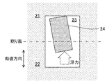
- FIG. 3 which is a side sectional view
- a core 24 having a shape corresponding to the internal space of the casting is disposed.
- FIG. 4 which is a side sectional view
- the core 24 is surrounded by the molten metal during casting and receives buoyancy in the vertical direction. Therefore, if there is no support portion for supporting the core 24, the core 24 will float. When the core 24 floats up, a casting with a displaced internal space is completed.
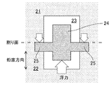
- FIG. 5 which is a side sectional view
- a surplus portion 25 called a baseboard protruding in the horizontal direction is provided in the core 24, and the upper die 21 and the lower die 22 are interposed via the surplus portion 25.
- the floating of the core 24 is prevented.
- the inside of the foam model is filled with casting sand to create the shape of the internal space, but a baseboard is provided outside the product to support the casting sand filled inside the foam model. I ca n’t do that. Therefore, during casting, the casting sand filled in the foamed model is surrounded by the molten metal, and “buoyed” is generated which floats by receiving buoyancy in the vertical direction.
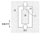
- FIG. 6 which is a side cross-sectional view
- a wide opening portion 17 is provided at the upper portion of the foam model 12 to communicate the outside of the foam model 12 surrounded by the casting sand 15 with the inside of the foam model.
- a product load higher than buoyancy is applied to the casting sand 16 filled in the model 12. This prevents the casting sand 16 filled in the foam model 12 from floating.
- the foamed model 12 cannot be provided with the wide opening portion 17, and the disappearance model casting method cannot be employed.
- An object of the present invention is to provide a disappearing model casting method capable of casting a casting having a good finished state by suppressing the casting sand filled in the foamed model from rising.
- a molten metal is poured into the mold to cause the foamed model to disappear.
- a molten metal is poured into the mold to cause the foamed model to disappear.
- an opening for communicating the outside of the mold and the cavity is provided in the foamed model, and the coating agent is provided in the opening.
- the volume of the cavity is defined as V (mm 3), ⁇ s (kg / mm 3) the bulk density of the molding sand to be filled in the cavity, the density of the molten metal ⁇ m (kg / mm 3), the angle of the opening with respect to the vertical direction theta,
- ⁇ b M Pa
- the cross-sectional shape of the opening, the angle of the opening, and the bending strength of the coating agent are selected so as to satisfy the following expression.
- an opening for communicating the outside of the mold with the cavity is provided in the foamed model, and the coating agent is applied to the opening.
- the cavity is supported by a coating agent applied to the opening.
- the coating agent for the opening that supports the cavity is a beam having a second moment of section I, a plate thickness h in the vertical direction, and a length L
- the above equation is derived from the beam theory. Therefore, by selecting the cross-sectional shape of the opening, the angle of the opening, and the bending strength of the coating agent so as to satisfy the above formula, the coating agent of the opening is prevented from being damaged. it can. Thereby, since it can suppress that the casting sand with which the inside of the foaming model was filled rises, a casting with a favorable finishing state can be cast.
- a mold formed by applying a coating agent on the surface of a foam model having a hollow portion therein is buried in casting sand (dry sand), and then a metal is placed in the mold.
- This is a method of casting a casting by pouring the molten metal and disappearing the foam model and replacing it with the molten metal.
- the hollow portion of the foam model is a hollow portion formed in the product by casting.
- the vanishing model casting method includes a melting step of melting metal (cast iron) to form a molten metal, a molding step of forming a foamed model, and a coating step of applying a coating agent on the surface of the foamed model to form a mold.
- the disappearance model casting method melts the foamed model by pouring molten metal (molten metal) into the casting mold and filling the casting sand into the casting mold by filling the casting mold in the casting sand.
- a casting step for replacing the molten metal has a cooling step of cooling the molten metal poured into the mold to form a casting, and a separation step of separating the casting from the casting sand.
- gray cast iron JIS-FC250
- flake graphite cast iron JIS-FC300
- a foam resin such as polystyrene foam
- a silica-based aggregate coating agent or the like can be used.
- the sand “silica sand” containing SiO 2 as a main component, zircon sand, chromite sand, synthetic ceramic sand and the like can be used.
- the thickness of the coating agent is preferably 3 mm or less. When the thickness of the coating agent is 3 mm or more, it is necessary to repeat coating and drying of the coating agent three times or more, which is troublesome and the thickness tends to be non-uniform.
- an opening for communicating the outside of the mold and the cavity is provided in the foam model, and a coating agent is applied to the opening, and the opening is formed so as to satisfy the following formula (1).
- the sectional shape of the part, the angle of the opening, and the bending strength of the coating agent are selected.
- ⁇ b is the bending strength (bending strength) (MPa) of the coating agent when the temperature becomes the highest during pouring
- V is the volume of the cavity
- ⁇ s is the bulk of the sand that fills the cavity.
- the density, ⁇ m is the density of the molten metal, and ⁇ is the angle of the opening with respect to the vertical direction.
- I is a secondary moment of section
- h is a plate thickness (mm) in the vertical direction
- L is a length (mm) of the beam.
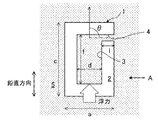
- FIG. 1 is a side sectional view of the mold
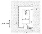
- FIG. 2 is a side view of FIG.
- the foam model 2 has a width of a (mm), a depth of b (mm), and a height of c (mm).
- the cavity 3 has a width d (mm), a depth e (mm), and a height f (mm).
- the opening 4 has a diameter of D (mm) and a length of 1 (mm).
- the mold 1 is covered with casting sand 5.
- the shape of the foam model 2 is not limited to a rectangular parallelepiped.
- the cavity 3 is supported by a coating agent applied to the opening 4.
- the coating agent for the opening 4 that supports the cavity 3 is assumed to be a beam having a cross-sectional secondary moment I, a vertical plate thickness h, and a length L. From the beam theory, when the maximum stress ⁇ max of the cantilever beam on which the buoyancy F acts on the end is obtained, it can be approximated as the following equation (3). It is assumed that the sand in the opening 4 does not bear a load.
- the coating agent is a tubular layer.
- the sectional secondary moment I can be expressed by the following formula (6).
- a coating agent having a hot strength ⁇ b that satisfies the formula (5) may be selected when the values obtained from the formula (6) and the formula (7) are substituted into the formula (5).
- the coating agent of the opening 4 is damaged by selecting the cross-sectional shape of the opening 4, the angle ⁇ of the opening 4, and the bending strength ⁇ b of the coating agent so as to satisfy the formula (12). You can avoid it.
- the coating agent of the opening 4 is prevented from being damaged by using the coating agent having the bending strength ⁇ b that satisfies the formula (12). Can do. Further, when the bending strength ⁇ b of the coating agent is determined, the cross-sectional shape and the angle ⁇ of the opening 4 are designed so that the second-order moment I satisfies the equation (12). The coating agent can be prevented from being damaged.
- the cavity was filled with “furan self-hardening sand”.
- This “furan self-hardening sand” is obtained by kneading sand, a resin and a curing agent.
- Sand used for self-hardening sand is silica sand (main component is SiO 2 ).
- the resin used for self-hardening sand as a binder is an acid curable furan resin containing furfuryl alcohol, and the amount of addition to the sand is 0.8%.
- curing agent used for self-hardening sand as a hardening catalyst is a hardening
- the bulk density ⁇ s of the self-hardening sand was 1.4 ⁇ 10 ⁇ 6 kg / mm 3 .
- the hot strength of the coating agent (the bending strength of the coating agent when the temperature becomes highest during pouring) is measured at the normal temperature (the coating agent is dried). Smaller than the bending strength). Therefore, in order to prevent “floating”, a coating agent having a bending strength at room temperature higher than 2.5 MPa, which is a hot strength, may be selected. Coating agent A was not adopted because it did not satisfy the formula (5). Coating agent B was selected because it had a bending strength at room temperature higher than 2.5 MPa. As a result, it was possible to cast a casting that did not “float”.
- the opening 4 for communicating the outside of the mold 1 and the cavity 3 is provided in the foamed model 2, and the coating agent is applied to the opening 4. Apply.
- the cavity 3 is supported by a coating agent applied to the opening 4.
- the coating agent for the opening 4 that supports the cavity 3 is a beam having a cross-sectional secondary moment I, a vertical plate thickness h, and a length L
- the above equation (12) is derived from the beam theory. Therefore, by selecting the cross-sectional shape of the opening 4, the angle of the opening 4, and the bending strength of the coating agent so as to satisfy the above formula (12), the coating agent of the opening 4 is damaged. You can avoid it. Thereby, since it can suppress that the casting sand with which the inside of the foam model 2 was filled rises, a casting with a favorable finishing state can be cast.
- the angle ⁇ of the opening 4 with respect to the vertical direction is 90 °
- the stress acting on the coating agent of the opening 4 is maximized.
- the coating agent of the opening 4 can be obtained. It can be prevented from being damaged.
Landscapes
- Engineering & Computer Science (AREA)
- Mechanical Engineering (AREA)
- Mold Materials And Core Materials (AREA)
- Molds, Cores, And Manufacturing Methods Thereof (AREA)
- Casting Devices For Molds (AREA)
Priority Applications (4)
| Application Number | Priority Date | Filing Date | Title |
|---|---|---|---|
| KR1020177012585A KR101949063B1 (ko) | 2014-11-18 | 2015-10-19 | 소실 모형 주조 방법 |
| US15/519,995 US10130989B2 (en) | 2014-11-18 | 2015-10-19 | Evaporate pattern casting method |
| CN201580061348.4A CN107107167B (zh) | 2014-11-18 | 2015-10-19 | 消失模铸造方法 |
| DE112015005190.2T DE112015005190B4 (de) | 2014-11-18 | 2015-10-19 | Verdampfungsmustergiessverfahren |
Applications Claiming Priority (2)
| Application Number | Priority Date | Filing Date | Title |
|---|---|---|---|
| JP2014233403A JP6284468B2 (ja) | 2014-11-18 | 2014-11-18 | 消失模型鋳造方法 |
| JP2014-233403 | 2014-11-18 |
Publications (1)
| Publication Number | Publication Date |
|---|---|
| WO2016080132A1 true WO2016080132A1 (ja) | 2016-05-26 |
Family
ID=56013689
Family Applications (1)
| Application Number | Title | Priority Date | Filing Date |
|---|---|---|---|
| PCT/JP2015/079474 Ceased WO2016080132A1 (ja) | 2014-11-18 | 2015-10-19 | 消失模型鋳造方法 |
Country Status (7)
| Country | Link |
|---|---|
| US (1) | US10130989B2 (enExample) |
| JP (1) | JP6284468B2 (enExample) |
| KR (1) | KR101949063B1 (enExample) |
| CN (1) | CN107107167B (enExample) |
| DE (1) | DE112015005190B4 (enExample) |
| TW (1) | TWI586455B (enExample) |
| WO (1) | WO2016080132A1 (enExample) |
Cited By (2)
| Publication number | Priority date | Publication date | Assignee | Title |
|---|---|---|---|---|
| CN106607545A (zh) * | 2016-08-31 | 2017-05-03 | 圣固(江苏)机械有限公司 | 一种油压卡钳及其制备方法 |
| CN112548042A (zh) * | 2019-09-10 | 2021-03-26 | 南阳二机石油装备集团股份有限公司 | 一种防止大型钻井泵铸造曲轴漂芯的方法及装置 |
Families Citing this family (2)
| Publication number | Priority date | Publication date | Assignee | Title |
|---|---|---|---|---|
| CN110614346B (zh) * | 2019-10-11 | 2020-11-03 | 柳州市顺昇机械有限公司 | 一种用消失模铸造工艺生产汽车模具的方法 |
| US12285798B2 (en) | 2020-06-01 | 2025-04-29 | LightSpeed Concepts Inc. | Tool-less method for making molds, cores, and temporary tools |
Citations (3)
| Publication number | Priority date | Publication date | Assignee | Title |
|---|---|---|---|---|
| JPH07124692A (ja) * | 1993-11-04 | 1995-05-16 | Sankyo Tekunika:Kk | ジャケット構造鋳物の鋳造方法 |
| JP2002321036A (ja) * | 2001-04-27 | 2002-11-05 | Kao Corp | 塗型剤及び塗装方法 |
| JP2008221288A (ja) * | 2007-03-14 | 2008-09-25 | Sintokogio Ltd | フルモールド鋳造法および該鋳造法に用いられる鋳型 |
Family Cites Families (15)
| Publication number | Priority date | Publication date | Assignee | Title |
|---|---|---|---|---|
| GB8529380D0 (en) * | 1985-11-29 | 1986-01-08 | Cosworth Res & Dev Ltd | Metal castings |
| JPS63183744A (ja) * | 1987-01-26 | 1988-07-29 | Nabeya:Kk | 多孔性鋳造品の製造方法 |
| JPH01266941A (ja) * | 1988-04-20 | 1989-10-24 | Mitsubishi Heavy Ind Ltd | 消失模型用塗型剤 |
| JPH0323032A (ja) * | 1989-06-20 | 1991-01-31 | Mazda Motor Corp | 鋳造用消失性模型の製造方法 |
| JPH04251631A (ja) * | 1991-01-23 | 1992-09-08 | Aisin Takaoka Ltd | 消失模型および消失模型鋳造法 |
| JPH0647485A (ja) * | 1992-08-03 | 1994-02-22 | Kubota Corp | 枝管付き菅の消失模型鋳造法 |
| JPH0899152A (ja) * | 1994-09-29 | 1996-04-16 | Kubota Corp | 消失模型鋳造用発泡模型 |
| JP3691430B2 (ja) * | 2001-11-20 | 2005-09-07 | 花王株式会社 | 消失模型鋳造法 |
| TW200539968A (en) * | 2004-06-15 | 2005-12-16 | shi-feng Huang | Vacuum lost form casting method |
| JP2006175492A (ja) * | 2004-12-24 | 2006-07-06 | Mie Katan Kogyo Kk | 消失模型鋳造法による鋳物の製造方法 |
| CN101607299B (zh) * | 2009-07-17 | 2011-09-21 | 泊头市青峰机械有限公司 | 大型复杂铸件的真空消失模铸造造型方法 |
| JP5491144B2 (ja) | 2009-11-26 | 2014-05-14 | 本田技研工業株式会社 | 消失模型鋳造法 |
| WO2011065410A1 (ja) | 2009-11-26 | 2011-06-03 | 本田技研工業株式会社 | 消失模型鋳造法 |
| US20130291463A1 (en) * | 2011-01-28 | 2013-11-07 | Yumi Kobayashi | Evaporative pattern for casting and casted product |
| CN103521703B (zh) * | 2013-09-18 | 2015-06-24 | 宁夏共享集团有限责任公司 | 一种防止消失模砂型漂移的方法 |
-
2014
- 2014-11-18 JP JP2014233403A patent/JP6284468B2/ja not_active Expired - Fee Related
-
2015
- 2015-10-19 WO PCT/JP2015/079474 patent/WO2016080132A1/ja not_active Ceased
- 2015-10-19 US US15/519,995 patent/US10130989B2/en not_active Expired - Fee Related
- 2015-10-19 CN CN201580061348.4A patent/CN107107167B/zh not_active Expired - Fee Related
- 2015-10-19 DE DE112015005190.2T patent/DE112015005190B4/de not_active Expired - Fee Related
- 2015-10-19 KR KR1020177012585A patent/KR101949063B1/ko not_active Expired - Fee Related
- 2015-11-03 TW TW104136165A patent/TWI586455B/zh not_active IP Right Cessation
Patent Citations (3)
| Publication number | Priority date | Publication date | Assignee | Title |
|---|---|---|---|---|
| JPH07124692A (ja) * | 1993-11-04 | 1995-05-16 | Sankyo Tekunika:Kk | ジャケット構造鋳物の鋳造方法 |
| JP2002321036A (ja) * | 2001-04-27 | 2002-11-05 | Kao Corp | 塗型剤及び塗装方法 |
| JP2008221288A (ja) * | 2007-03-14 | 2008-09-25 | Sintokogio Ltd | フルモールド鋳造法および該鋳造法に用いられる鋳型 |
Cited By (2)
| Publication number | Priority date | Publication date | Assignee | Title |
|---|---|---|---|---|
| CN106607545A (zh) * | 2016-08-31 | 2017-05-03 | 圣固(江苏)机械有限公司 | 一种油压卡钳及其制备方法 |
| CN112548042A (zh) * | 2019-09-10 | 2021-03-26 | 南阳二机石油装备集团股份有限公司 | 一种防止大型钻井泵铸造曲轴漂芯的方法及装置 |
Also Published As
| Publication number | Publication date |
|---|---|
| TW201634148A (zh) | 2016-10-01 |
| US10130989B2 (en) | 2018-11-20 |
| US20170312812A1 (en) | 2017-11-02 |
| TWI586455B (zh) | 2017-06-11 |
| JP6284468B2 (ja) | 2018-02-28 |
| DE112015005190T5 (de) | 2017-08-24 |
| CN107107167A (zh) | 2017-08-29 |
| KR101949063B1 (ko) | 2019-02-15 |
| DE112015005190B4 (de) | 2022-11-24 |
| JP2016097409A (ja) | 2016-05-30 |
| CN107107167B (zh) | 2019-03-01 |
| KR20170070119A (ko) | 2017-06-21 |
Similar Documents
| Publication | Publication Date | Title |
|---|---|---|
| JP6284468B2 (ja) | 消失模型鋳造方法 | |
| JP6096378B1 (ja) | 3次元積層造形鋳型製造用粒状材料の製造方法および3次元積層造形鋳型の製造方法 | |
| KR20120099278A (ko) | 유기산염을 포함하는 주조 혼합물 및 그 사용 방법 | |
| JP6470141B2 (ja) | 消失模型鋳造方法 | |
| JP6275024B2 (ja) | 浮力伝達治具 | |
| JP6231465B2 (ja) | 消失模型鋳造方法 | |
| JP6014087B2 (ja) | 消失模型鋳造方法 | |
| JP6172456B2 (ja) | 発泡砂を用いた砂型の成形方法、成形用金型及び砂型 | |
| JP4336474B2 (ja) | 自硬性流動鋳型造型法 | |
| CN105149518A (zh) | 一种砂芯及用砂芯进行深孔铸造成型的方法 | |
| JP2021016896A (ja) | 横穴の鋳抜き可否評価方法 | |
| WO2000027562A1 (en) | Casting mold assembly | |
| JP2018196889A (ja) | 中子の変形量予測方法 | |
| JP2011020165A (ja) | 鋳物砂、及びこれを用いた鋳型 | |
| PL188573B1 (pl) | Samoutwardzalna masa formierska i rdzeniowa oraz sposób wytwarzania form, zwłaszcza dla ciężkich odlewów staliwnych i żeliwnych |
Legal Events
| Date | Code | Title | Description |
|---|---|---|---|
| 121 | Ep: the epo has been informed by wipo that ep was designated in this application |
Ref document number: 15860904 Country of ref document: EP Kind code of ref document: A1 |
|
| WWE | Wipo information: entry into national phase |
Ref document number: 15519995 Country of ref document: US |
|
| ENP | Entry into the national phase |
Ref document number: 20177012585 Country of ref document: KR Kind code of ref document: A |
|
| WWE | Wipo information: entry into national phase |
Ref document number: 112015005190 Country of ref document: DE |
|
| 122 | Ep: pct application non-entry in european phase |
Ref document number: 15860904 Country of ref document: EP Kind code of ref document: A1 |