WO2016080132A1 - Evaporative pattern casting method - Google Patents
Evaporative pattern casting method Download PDFInfo
- Publication number
- WO2016080132A1 WO2016080132A1 PCT/JP2015/079474 JP2015079474W WO2016080132A1 WO 2016080132 A1 WO2016080132 A1 WO 2016080132A1 JP 2015079474 W JP2015079474 W JP 2015079474W WO 2016080132 A1 WO2016080132 A1 WO 2016080132A1
- Authority
- WO
- WIPO (PCT)
- Prior art keywords
- opening
- coating agent
- casting
- cavity
- model
- Prior art date
Links
Images

Classifications
-
- B—PERFORMING OPERATIONS; TRANSPORTING
- B22—CASTING; POWDER METALLURGY
- B22C—FOUNDRY MOULDING
- B22C9/00—Moulds or cores; Moulding processes
- B22C9/02—Sand moulds or like moulds for shaped castings
- B22C9/04—Use of lost patterns
-
- B—PERFORMING OPERATIONS; TRANSPORTING
- B22—CASTING; POWDER METALLURGY
- B22C—FOUNDRY MOULDING
- B22C9/00—Moulds or cores; Moulding processes
- B22C9/02—Sand moulds or like moulds for shaped castings
- B22C9/04—Use of lost patterns
- B22C9/046—Use of patterns which are eliminated by the liquid metal in the mould
-
- B—PERFORMING OPERATIONS; TRANSPORTING
- B22—CASTING; POWDER METALLURGY
- B22C—FOUNDRY MOULDING
- B22C21/00—Flasks; Accessories therefor
- B22C21/12—Accessories
- B22C21/14—Accessories for reinforcing or securing moulding materials or cores, e.g. gaggers, chaplets, pins, bars
-
- B—PERFORMING OPERATIONS; TRANSPORTING
- B22—CASTING; POWDER METALLURGY
- B22C—FOUNDRY MOULDING
- B22C3/00—Selection of compositions for coating the surfaces of moulds, cores, or patterns
-
- B—PERFORMING OPERATIONS; TRANSPORTING
- B22—CASTING; POWDER METALLURGY
- B22C—FOUNDRY MOULDING
- B22C7/00—Patterns; Manufacture thereof so far as not provided for in other classes
- B22C7/02—Lost patterns
- B22C7/023—Patterns made from expanded plastic materials
-
- B—PERFORMING OPERATIONS; TRANSPORTING
- B22—CASTING; POWDER METALLURGY
- B22C—FOUNDRY MOULDING
- B22C9/00—Moulds or cores; Moulding processes
- B22C9/02—Sand moulds or like moulds for shaped castings
-
- B—PERFORMING OPERATIONS; TRANSPORTING
- B22—CASTING; POWDER METALLURGY
- B22C—FOUNDRY MOULDING
- B22C9/00—Moulds or cores; Moulding processes
- B22C9/10—Cores; Manufacture or installation of cores
Definitions
- the present invention relates to a vanishing model casting method for casting a casting.
- the disappearance model casting method a mold made by applying a coating agent to the surface of the foam model is buried in the casting sand, and then the molten metal is poured into the mold to eliminate the foam model and replace it with the molten metal. In this method, the casting is cast.
- Patent Document 1 discloses a disappearance model casting method in which the casting time during casting is set according to the modulus of the model (model volume / model surface area).
- FIG. 3 which is a side sectional view
- a core 24 having a shape corresponding to the internal space of the casting is disposed.
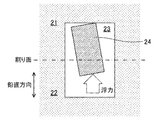
- FIG. 4 which is a side sectional view
- the core 24 is surrounded by the molten metal during casting and receives buoyancy in the vertical direction. Therefore, if there is no support portion for supporting the core 24, the core 24 will float. When the core 24 floats up, a casting with a displaced internal space is completed.
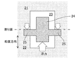
- FIG. 5 which is a side sectional view
- a surplus portion 25 called a baseboard protruding in the horizontal direction is provided in the core 24, and the upper die 21 and the lower die 22 are interposed via the surplus portion 25.
- the floating of the core 24 is prevented.
- the inside of the foam model is filled with casting sand to create the shape of the internal space, but a baseboard is provided outside the product to support the casting sand filled inside the foam model. I ca n’t do that. Therefore, during casting, the casting sand filled in the foamed model is surrounded by the molten metal, and “buoyed” is generated which floats by receiving buoyancy in the vertical direction.
- FIG. 6 which is a side cross-sectional view
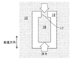
- a wide opening portion 17 is provided at the upper portion of the foam model 12 to communicate the outside of the foam model 12 surrounded by the casting sand 15 with the inside of the foam model.
- a product load higher than buoyancy is applied to the casting sand 16 filled in the model 12. This prevents the casting sand 16 filled in the foam model 12 from floating.
- the foamed model 12 cannot be provided with the wide opening portion 17, and the disappearance model casting method cannot be employed.
- An object of the present invention is to provide a disappearing model casting method capable of casting a casting having a good finished state by suppressing the casting sand filled in the foamed model from rising.
- a molten metal is poured into the mold to cause the foamed model to disappear.
- a molten metal is poured into the mold to cause the foamed model to disappear.
- an opening for communicating the outside of the mold and the cavity is provided in the foamed model, and the coating agent is provided in the opening.
- the volume of the cavity is defined as V (mm 3), ⁇ s (kg / mm 3) the bulk density of the molding sand to be filled in the cavity, the density of the molten metal ⁇ m (kg / mm 3), the angle of the opening with respect to the vertical direction theta,
- ⁇ b M Pa
- the cross-sectional shape of the opening, the angle of the opening, and the bending strength of the coating agent are selected so as to satisfy the following expression.
- an opening for communicating the outside of the mold with the cavity is provided in the foamed model, and the coating agent is applied to the opening.
- the cavity is supported by a coating agent applied to the opening.
- the coating agent for the opening that supports the cavity is a beam having a second moment of section I, a plate thickness h in the vertical direction, and a length L
- the above equation is derived from the beam theory. Therefore, by selecting the cross-sectional shape of the opening, the angle of the opening, and the bending strength of the coating agent so as to satisfy the above formula, the coating agent of the opening is prevented from being damaged. it can. Thereby, since it can suppress that the casting sand with which the inside of the foaming model was filled rises, a casting with a favorable finishing state can be cast.
- a mold formed by applying a coating agent on the surface of a foam model having a hollow portion therein is buried in casting sand (dry sand), and then a metal is placed in the mold.
- This is a method of casting a casting by pouring the molten metal and disappearing the foam model and replacing it with the molten metal.
- the hollow portion of the foam model is a hollow portion formed in the product by casting.
- the vanishing model casting method includes a melting step of melting metal (cast iron) to form a molten metal, a molding step of forming a foamed model, and a coating step of applying a coating agent on the surface of the foamed model to form a mold.
- the disappearance model casting method melts the foamed model by pouring molten metal (molten metal) into the casting mold and filling the casting sand into the casting mold by filling the casting mold in the casting sand.
- a casting step for replacing the molten metal has a cooling step of cooling the molten metal poured into the mold to form a casting, and a separation step of separating the casting from the casting sand.
- gray cast iron JIS-FC250
- flake graphite cast iron JIS-FC300
- a foam resin such as polystyrene foam
- a silica-based aggregate coating agent or the like can be used.
- the sand “silica sand” containing SiO 2 as a main component, zircon sand, chromite sand, synthetic ceramic sand and the like can be used.
- the thickness of the coating agent is preferably 3 mm or less. When the thickness of the coating agent is 3 mm or more, it is necessary to repeat coating and drying of the coating agent three times or more, which is troublesome and the thickness tends to be non-uniform.
- an opening for communicating the outside of the mold and the cavity is provided in the foam model, and a coating agent is applied to the opening, and the opening is formed so as to satisfy the following formula (1).
- the sectional shape of the part, the angle of the opening, and the bending strength of the coating agent are selected.
- ⁇ b is the bending strength (bending strength) (MPa) of the coating agent when the temperature becomes the highest during pouring
- V is the volume of the cavity
- ⁇ s is the bulk of the sand that fills the cavity.
- the density, ⁇ m is the density of the molten metal, and ⁇ is the angle of the opening with respect to the vertical direction.
- I is a secondary moment of section
- h is a plate thickness (mm) in the vertical direction
- L is a length (mm) of the beam.
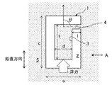
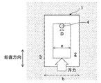
- FIG. 1 is a side sectional view of the mold
- FIG. 2 is a side view of FIG.
- the foam model 2 has a width of a (mm), a depth of b (mm), and a height of c (mm).
- the cavity 3 has a width d (mm), a depth e (mm), and a height f (mm).
- the opening 4 has a diameter of D (mm) and a length of 1 (mm).
- the mold 1 is covered with casting sand 5.
- the shape of the foam model 2 is not limited to a rectangular parallelepiped.
- the cavity 3 is supported by a coating agent applied to the opening 4.
- the coating agent for the opening 4 that supports the cavity 3 is assumed to be a beam having a cross-sectional secondary moment I, a vertical plate thickness h, and a length L. From the beam theory, when the maximum stress ⁇ max of the cantilever beam on which the buoyancy F acts on the end is obtained, it can be approximated as the following equation (3). It is assumed that the sand in the opening 4 does not bear a load.
- the coating agent is a tubular layer.
- the sectional secondary moment I can be expressed by the following formula (6).
- a coating agent having a hot strength ⁇ b that satisfies the formula (5) may be selected when the values obtained from the formula (6) and the formula (7) are substituted into the formula (5).
- the coating agent of the opening 4 is damaged by selecting the cross-sectional shape of the opening 4, the angle ⁇ of the opening 4, and the bending strength ⁇ b of the coating agent so as to satisfy the formula (12). You can avoid it.
- the coating agent of the opening 4 is prevented from being damaged by using the coating agent having the bending strength ⁇ b that satisfies the formula (12). Can do. Further, when the bending strength ⁇ b of the coating agent is determined, the cross-sectional shape and the angle ⁇ of the opening 4 are designed so that the second-order moment I satisfies the equation (12). The coating agent can be prevented from being damaged.
- the cavity was filled with “furan self-hardening sand”.
- This “furan self-hardening sand” is obtained by kneading sand, a resin and a curing agent.
- Sand used for self-hardening sand is silica sand (main component is SiO 2 ).
- the resin used for self-hardening sand as a binder is an acid curable furan resin containing furfuryl alcohol, and the amount of addition to the sand is 0.8%.
- curing agent used for self-hardening sand as a hardening catalyst is a hardening
- the bulk density ⁇ s of the self-hardening sand was 1.4 ⁇ 10 ⁇ 6 kg / mm 3 .
- the hot strength of the coating agent (the bending strength of the coating agent when the temperature becomes highest during pouring) is measured at the normal temperature (the coating agent is dried). Smaller than the bending strength). Therefore, in order to prevent “floating”, a coating agent having a bending strength at room temperature higher than 2.5 MPa, which is a hot strength, may be selected. Coating agent A was not adopted because it did not satisfy the formula (5). Coating agent B was selected because it had a bending strength at room temperature higher than 2.5 MPa. As a result, it was possible to cast a casting that did not “float”.
- the opening 4 for communicating the outside of the mold 1 and the cavity 3 is provided in the foamed model 2, and the coating agent is applied to the opening 4. Apply.
- the cavity 3 is supported by a coating agent applied to the opening 4.
- the coating agent for the opening 4 that supports the cavity 3 is a beam having a cross-sectional secondary moment I, a vertical plate thickness h, and a length L
- the above equation (12) is derived from the beam theory. Therefore, by selecting the cross-sectional shape of the opening 4, the angle of the opening 4, and the bending strength of the coating agent so as to satisfy the above formula (12), the coating agent of the opening 4 is damaged. You can avoid it. Thereby, since it can suppress that the casting sand with which the inside of the foam model 2 was filled rises, a casting with a favorable finishing state can be cast.
- the angle ⁇ of the opening 4 with respect to the vertical direction is 90 °
- the stress acting on the coating agent of the opening 4 is maximized.
- the coating agent of the opening 4 can be obtained. It can be prevented from being damaged.
Landscapes
- Engineering & Computer Science (AREA)
- Mechanical Engineering (AREA)
- Mold Materials And Core Materials (AREA)
- Molds, Cores, And Manufacturing Methods Thereof (AREA)
- Casting Devices For Molds (AREA)
Abstract
Description
σbI>V(ρm-ρs){(hL/2)sinθ-cosθ} In the present invention, after filling a mold formed by applying a coating agent on the surface of a foamed model having a hollow portion in casting sand, a molten metal is poured into the mold to cause the foamed model to disappear. In the vanishing model casting method in which a casting is cast by replacing the molten metal, an opening for communicating the outside of the mold and the cavity is provided in the foamed model, and the coating agent is provided in the opening. When the coating agent applied to the opening is regarded as a beam having a cross-sectional secondary moment of I, a vertical plate thickness of h, and a length of L, the volume of the cavity is defined as V (mm 3), ρs (kg / mm 3) the bulk density of the molding sand to be filled in the cavity, the density of the molten metal ρm (kg / mm 3), the angle of the opening with respect to the vertical direction theta, The bending strength of the coating agent when the temperature becomes the highest during pouring is expressed as σb (M Pa), the cross-sectional shape of the opening, the angle of the opening, and the bending strength of the coating agent are selected so as to satisfy the following expression.
σbI> V (ρm−ρs) {(hL / 2) sinθ−cosθ}
本発明の実施形態による消失模型鋳造方法は、内部に空洞部を有する発泡模型の表面に塗型剤を塗布してなる鋳型を鋳砂(乾燥砂)の中に埋めた後に、鋳型内に金属の溶湯を注ぎ込み、発泡模型を消失させて溶湯と置換することで、鋳物を鋳造する方法である。なお、発泡模型の空洞部は、鋳造によって製品内に形成される空洞部分である。 (Disappearance model casting method)
In the disappearance model casting method according to the embodiment of the present invention, a mold formed by applying a coating agent on the surface of a foam model having a hollow portion therein is buried in casting sand (dry sand), and then a metal is placed in the mold. This is a method of casting a casting by pouring the molten metal and disappearing the foam model and replacing it with the molten metal. The hollow portion of the foam model is a hollow portion formed in the product by casting.
σbI>V(ρm-ρs){(hL/2)sinθ-cosθ} ・・・式(1)
ここで、σbは注湯時に最も温度が高くなったときの塗型剤の抗折強度(曲げ強さ)(MPa)、Vは空洞部の体積、ρsは空洞部に充填する鋳砂のかさ密度、ρmは溶湯の密度、θは鉛直方向に対する開口部の角度である。また、開口部に塗布した塗型剤を梁とみなしたときに、Iは断面2次モーメント、hは鉛直方向の板厚(mm)、Lは梁の長さ(mm)である。 Here, in the present embodiment, an opening for communicating the outside of the mold and the cavity is provided in the foam model, and a coating agent is applied to the opening, and the opening is formed so as to satisfy the following formula (1). The sectional shape of the part, the angle of the opening, and the bending strength of the coating agent are selected.
σbI> V (ρm−ρs) {(hL / 2) sinθ−cosθ} (1)
Here, σb is the bending strength (bending strength) (MPa) of the coating agent when the temperature becomes the highest during pouring, V is the volume of the cavity, and ρs is the bulk of the sand that fills the cavity. The density, ρm is the density of the molten metal, and θ is the angle of the opening with respect to the vertical direction. Further, when the coating agent applied to the opening is regarded as a beam, I is a secondary moment of section, h is a plate thickness (mm) in the vertical direction, and L is a length (mm) of the beam.
図1は鋳型の側面断面図であり、図2は図1をA方向から見た側面図である。ここで、図1および図2に示すように、空洞部3を内部に有する直方体の発泡模型2に、発泡模型2の外部と空洞部3とを連通させる開口部4が水平方向(θ=90°)に設けられた鋳型1を用いて、内部に空洞部3を備えた鋳物を鋳造する場合について考える。ここで、発泡模型2は、幅がa(mm)、奥行きがb(mm)、高さがc(mm)である。また、空洞部3は、幅がd(mm)、奥行きがe(mm)、高さがf(mm)である。また、開口部4は、直径がD(mm)で長さがl(mm)である。また、鋳型1のまわりは鋳砂5で覆われている。なお、発泡模型2の形状は直方体に限定されない。 (Strength of coating agent)
FIG. 1 is a side sectional view of the mold, and FIG. 2 is a side view of FIG. Here, as shown in FIGS. 1 and 2, a rectangular
F=V(ρm-ρs) ・・・式(2) First, from Archimedes' principle, the buoyancy F acting on the
F = V (ρm−ρs) (2)
σmax =M/I×t/2=hFL/2I=hV(ρm-ρs)L/2I ・・・式(3) During casting, the
σmax = M / I × t / 2 = hFL / 2I = hV (ρm−ρs) L / 2I (3)
σb>σmax ・・・式(4) When the bending strength (hot strength) of the coating agent when the temperature becomes the highest during pouring is σb, the coating agent in the
σb> σmax (4)
σbI>hV(ρm-ρs)L/2 ・・・式(5) Substituting equation (3) into equation (4) yields equation (5).
σbI> hV (ρm−ρs) L / 2 Formula (5)
I=π{D4-(D-2t)4}/64 ・・・式(6)
h=D/2 ・・・式(7) For example, if the
I = π {D 4 − (D−2t) 4 } / 64 (6)
h = D / 2 Formula (7)
また、式(5)を変形すると、式(8)となる。
I>hV(ρm-ρs)L/2σb ・・・式(8) (Cross sectional shape of the opening)
Further, when Expression (5) is modified, Expression (8) is obtained.
I> hV (ρm−ρs) L / 2σb Equation (8)
ここで、上記した開口部4は、水平方向(θ=90°)に設けられている。開口部4を水平方向(θ=90°)に設けると、開口部4の塗型剤に作用する応力が最大となる。しかし、開口部4の角度を変えると、開口部4の塗型剤に作用する応力σmax を低減させることができる。鉛直方向に対する開口部4の角度をθ(0°≦θ≦180°)とし、開口部4の塗型剤を梁と仮定すると、浮力の軸方向成分Faは、以下の式(9)となり、その直角方向成分Fvは、以下の式(10)となる。
Fa=Fcosθ ・・・式(9)
Fv=Fsinθ ・・・式(10) (Opening angle)
Here, the
Fa = Fcos θ (9)
Fv = Fsinθ (10)
σmax =M/I×t/2-Fa=hFvL/2I-Fa
=V(ρm-ρs){(hL/2I)sinθ-cosθ} ・・・式(11) When the cross-sectional area of the coating agent in the
σmax = M / I × t / 2−Fa = hFvL / 2I−Fa
= V (ρm−ρs) {(hL / 2I) sinθ−cosθ} (11)
σbI>V(ρm-ρs){(hL/2)sinθ-cosθ} ・・・式(12) Substituting equation (11) into equation (4) yields equation (12).
σbI> V (ρm−ρs) {(hL / 2) sinθ−cosθ} (12)
次に、ねずみ鋳鉄(JIS-FC250)を溶湯として用いて、直方体の発泡模型の内部に、直方体の空洞部をもうけ、直径Dが16mmで長さlが25mmの開口部を水平方向(θ=90°)に配置した鋳型を用いて、鋳物を鋳造した。ここで、発泡模型は、図1および図2において、幅aが100mm、奥行きbが100mm、高さcが200mmであった。また、空洞部は、幅dが50mm、奥行きeが50mm、高さfが100mmであった。また、ねずみ鋳鉄の密度ρmは7.1×10⁻⁶ kg/mm3であった。塗型剤の種類を表1に示す。 (Example)
Next, using gray cast iron (JIS-FC250) as a molten metal, a rectangular parallelepiped cavity is provided inside the rectangular foam model, and an opening having a diameter D of 16 mm and a length l of 25 mm is formed in a horizontal direction (θ = The casting was cast using a mold placed at 90 °. Here, in FIGS. 1 and 2, the foam model had a width a of 100 mm, a depth b of 100 mm, and a height c of 200 mm. The hollow portion had a width d of 50 mm, a depth e of 50 mm, and a height f of 100 mm. The density ρm of gray cast iron was 7.1 × 10 −6 kg / mm 3 . Table 1 shows the types of coating agents.

F=V(ρm-ρs)=50×50×100×(7.1-1.4)
=1.4kgf=14N Substituting the density of gray cast iron and the bulk density of self-hardening sand into Equation (2) yields:
F = V (ρm−ρs) = 50 × 50 × 100 × (7.1-1.4)
= 1.4kgf = 14N
I=π{164-(16-2×0.8)4}/64=1.1×103 Here, a coating agent having an unknown hot strength σb was applied twice, and the average thickness of the coating agent was 0.8 mm. It is difficult to directly measure the hot strength of the coating agent. When substituting into the equation (5) and obtaining the cross-sectional secondary moment I of the coating agent at the opening, it is as follows.
I = π {16 4 − (16−2 × 0.8) 4 } /64=1.1×10 3
hV(ρm-ρs)L/2I=8×14×25/(1.1×103)
=2.5MPa Moreover, the right side of Formula (3) is as follows.
hV (ρm−ρs) L / 2I = 8 × 14 × 25 / (1.1 × 10 3 )
= 2.5 MPa
以上に述べたように、本実施形態に係る消失模型鋳造方法によると、鋳型1の外部と空洞部3とを連通させる開口部4を発泡模型2に設けて、開口部4に塗型剤を塗布する。鋳造に際し、空洞部3は、開口部4に塗布した塗型剤によって支持される。空洞部3を支持する開口部4の塗型剤を、断面2次モーメントI、鉛直方向の板厚h、長さLの梁と仮定すると、梁理論から上記の式(12)が導かれる。そこで、開口部4の断面形状、開口部4の角度、および、塗型剤の抗折強度を、上記の式(12)を満たすように選定することで、開口部4の塗型剤が損傷しないようにすることができる。これにより、発泡模型2の内部に充填した鋳砂が浮上するのを抑制することができるので、仕上がり状態が良好な鋳物を鋳造することができる。 (effect)
As described above, according to the disappearance model casting method according to the present embodiment, the
2 発泡模型
3 空洞部
4 開口部
5 鋳砂
12 発泡模型
15 鋳砂
16 鋳砂
17 開口部分
21 上型
22 下型
23 空洞
24 中子
25 余剰部 DESCRIPTION OF SYMBOLS 1
Claims (2)
- 内部に空洞部を有する発泡模型の表面に塗型剤を塗布してなる鋳型を鋳砂の中に埋めた後に、前記鋳型内に金属の溶湯を注ぎ込み、前記発泡模型を消失させて前記溶湯と置換することで、鋳物を鋳造する消失模型鋳造方法において、
前記鋳型の外部と前記空洞部とを連通させる開口部を前記発泡模型に設けて、前記開口部に前記塗型剤を塗布するとともに、
前記開口部に塗布した前記塗型剤を、断面2次モーメントがI、鉛直方向の板厚がh、長さがLの梁とみなしたときに、前記空洞部の体積をV(mm3)、前記空洞部に充填する前記鋳砂のかさ密度をρs(kg/mm3)、前記溶湯の密度をρm(kg/mm3)、鉛直方向に対する前記開口部の角度をθ、注湯時に最も温度が高くなったときの前記塗型剤の抗折強度をσb(MPa)とすると、以下の式を満たすように、前記開口部の断面形状、前記開口部の角度、および、前記塗型剤の抗折強度を選定することを特徴とする消失模型鋳造方法。
σbI>V(ρm-ρs){(hL/2)sinθ-cosθ} After filling the mold formed by applying a coating agent on the surface of the foam model having a hollow portion in the casting sand, the molten metal is poured into the mold, the foam model is disappeared and the melt In the disappearing model casting method of casting a casting by replacing,
An opening for communicating the outside of the mold and the cavity is provided in the foam model, and the coating agent is applied to the opening,
When the coating agent applied to the opening is regarded as a beam having a moment of inertia of cross section of I, a plate thickness in the vertical direction of h, and a length of L, the volume of the cavity is defined as V (mm 3 ). , ρs (kg / mm 3) the bulk density of the molding sand to be filled in the cavity, the density of the molten metal ρm (kg / mm 3), the angle of the opening with respect to the vertical direction theta, most during pouring When the bending strength of the coating agent when the temperature becomes high is σb (MPa), the cross-sectional shape of the opening, the angle of the opening, and the coating agent so as to satisfy the following formula: An evanescent model casting method characterized by selecting the bending strength of the steel.
σbI> V (ρm−ρs) {(hL / 2) sinθ−cosθ} - 鉛直方向に対する前記開口部の角度θを90°とすることを特徴とする請求項1に記載の消失模型鋳造方法。 The vanishing model casting method according to claim 1, wherein an angle θ of the opening with respect to the vertical direction is set to 90 °.
Priority Applications (4)
| Application Number | Priority Date | Filing Date | Title |
|---|---|---|---|
| CN201580061348.4A CN107107167B (en) | 2014-11-18 | 2015-10-19 | Lost-foam casting method |
| DE112015005190.2T DE112015005190B4 (en) | 2014-11-18 | 2015-10-19 | evaporation pattern casting process |
| US15/519,995 US10130989B2 (en) | 2014-11-18 | 2015-10-19 | Evaporate pattern casting method |
| KR1020177012585A KR101949063B1 (en) | 2014-11-18 | 2015-10-19 | Evaporative pattern casting method |
Applications Claiming Priority (2)
| Application Number | Priority Date | Filing Date | Title |
|---|---|---|---|
| JP2014233403A JP6284468B2 (en) | 2014-11-18 | 2014-11-18 | Disappearance model casting method |
| JP2014-233403 | 2014-11-18 |
Publications (1)
| Publication Number | Publication Date |
|---|---|
| WO2016080132A1 true WO2016080132A1 (en) | 2016-05-26 |
Family
ID=56013689
Family Applications (1)
| Application Number | Title | Priority Date | Filing Date |
|---|---|---|---|
| PCT/JP2015/079474 WO2016080132A1 (en) | 2014-11-18 | 2015-10-19 | Evaporative pattern casting method |
Country Status (7)
| Country | Link |
|---|---|
| US (1) | US10130989B2 (en) |
| JP (1) | JP6284468B2 (en) |
| KR (1) | KR101949063B1 (en) |
| CN (1) | CN107107167B (en) |
| DE (1) | DE112015005190B4 (en) |
| TW (1) | TWI586455B (en) |
| WO (1) | WO2016080132A1 (en) |
Cited By (2)
| Publication number | Priority date | Publication date | Assignee | Title |
|---|---|---|---|---|
| CN106607545A (en) * | 2016-08-31 | 2017-05-03 | 圣固(江苏)机械有限公司 | Oil pressure calipers and preparation method thereof |
| CN112548042A (en) * | 2019-09-10 | 2021-03-26 | 南阳二机石油装备集团股份有限公司 | Method and device for preventing large drilling pump from casting crankshaft floating core |
Families Citing this family (1)
| Publication number | Priority date | Publication date | Assignee | Title |
|---|---|---|---|---|
| CN110614346B (en) * | 2019-10-11 | 2020-11-03 | 柳州市顺昇机械有限公司 | Method for producing automobile mold by lost foam casting process |
Citations (3)
| Publication number | Priority date | Publication date | Assignee | Title |
|---|---|---|---|---|
| JPH07124692A (en) * | 1993-11-04 | 1995-05-16 | Sankyo Tekunika:Kk | Method for casting jacket structural cast product |
| JP2002321036A (en) * | 2001-04-27 | 2002-11-05 | Kao Corp | Facing material and coating method |
| JP2008221288A (en) * | 2007-03-14 | 2008-09-25 | Sintokogio Ltd | Full-mold casting method and mold for use in the casting method |
Family Cites Families (15)
| Publication number | Priority date | Publication date | Assignee | Title |
|---|---|---|---|---|
| GB8529380D0 (en) * | 1985-11-29 | 1986-01-08 | Cosworth Res & Dev Ltd | Metal castings |
| JPS63183744A (en) * | 1987-01-26 | 1988-07-29 | Nabeya:Kk | Production of porous casting |
| JPH01266941A (en) * | 1988-04-20 | 1989-10-24 | Mitsubishi Heavy Ind Ltd | Facing agent for lost foam pattern |
| JPH0323032A (en) * | 1989-06-20 | 1991-01-31 | Mazda Motor Corp | Manufacture of lost foam pattern for casting |
| JPH04251631A (en) * | 1991-01-23 | 1992-09-08 | Aisin Takaoka Ltd | Lost foam pattern and lost foam pattern casting method |
| JPH0647485A (en) * | 1992-08-03 | 1994-02-22 | Kubota Corp | Lost foam pattern casting method for pipe with branched pipe |
| JPH0899152A (en) * | 1994-09-29 | 1996-04-16 | Kubota Corp | Foamed pattern for casting lost foam pattern |
| JP3691430B2 (en) * | 2001-11-20 | 2005-09-07 | 花王株式会社 | Vanishing model casting method |
| TW200539968A (en) * | 2004-06-15 | 2005-12-16 | shi-feng Huang | Vacuum lost form casting method |
| JP2006175492A (en) * | 2004-12-24 | 2006-07-06 | Mie Katan Kogyo Kk | Method for manufacturing casting with lost-foam pattern casting method |
| CN101607299B (en) * | 2009-07-17 | 2011-09-21 | 泊头市青峰机械有限公司 | Vacuum expendable pattern casting (V-EPC) molding method of large complex castings |
| JP5491144B2 (en) | 2009-11-26 | 2014-05-14 | 本田技研工業株式会社 | Vanishing model casting method |
| WO2011065410A1 (en) * | 2009-11-26 | 2011-06-03 | 本田技研工業株式会社 | Evaporative pattern casing process |
| JP5445680B2 (en) * | 2011-01-28 | 2014-03-19 | トヨタ自動車株式会社 | Disappearance models and castings for casting |
| CN103521703B (en) * | 2013-09-18 | 2015-06-24 | 宁夏共享集团有限责任公司 | Method for preventing shifting of lost foam sand model |
-
2014
- 2014-11-18 JP JP2014233403A patent/JP6284468B2/en not_active Expired - Fee Related
-
2015
- 2015-10-19 US US15/519,995 patent/US10130989B2/en not_active Expired - Fee Related
- 2015-10-19 KR KR1020177012585A patent/KR101949063B1/en active IP Right Grant
- 2015-10-19 DE DE112015005190.2T patent/DE112015005190B4/en not_active Expired - Fee Related
- 2015-10-19 CN CN201580061348.4A patent/CN107107167B/en not_active Expired - Fee Related
- 2015-10-19 WO PCT/JP2015/079474 patent/WO2016080132A1/en active Application Filing
- 2015-11-03 TW TW104136165A patent/TWI586455B/en not_active IP Right Cessation
Patent Citations (3)
| Publication number | Priority date | Publication date | Assignee | Title |
|---|---|---|---|---|
| JPH07124692A (en) * | 1993-11-04 | 1995-05-16 | Sankyo Tekunika:Kk | Method for casting jacket structural cast product |
| JP2002321036A (en) * | 2001-04-27 | 2002-11-05 | Kao Corp | Facing material and coating method |
| JP2008221288A (en) * | 2007-03-14 | 2008-09-25 | Sintokogio Ltd | Full-mold casting method and mold for use in the casting method |
Cited By (2)
| Publication number | Priority date | Publication date | Assignee | Title |
|---|---|---|---|---|
| CN106607545A (en) * | 2016-08-31 | 2017-05-03 | 圣固(江苏)机械有限公司 | Oil pressure calipers and preparation method thereof |
| CN112548042A (en) * | 2019-09-10 | 2021-03-26 | 南阳二机石油装备集团股份有限公司 | Method and device for preventing large drilling pump from casting crankshaft floating core |
Also Published As
| Publication number | Publication date |
|---|---|
| US20170312812A1 (en) | 2017-11-02 |
| DE112015005190B4 (en) | 2022-11-24 |
| DE112015005190T5 (en) | 2017-08-24 |
| US10130989B2 (en) | 2018-11-20 |
| CN107107167B (en) | 2019-03-01 |
| TW201634148A (en) | 2016-10-01 |
| KR101949063B1 (en) | 2019-02-15 |
| CN107107167A (en) | 2017-08-29 |
| TWI586455B (en) | 2017-06-11 |
| KR20170070119A (en) | 2017-06-21 |
| JP2016097409A (en) | 2016-05-30 |
| JP6284468B2 (en) | 2018-02-28 |
Similar Documents
| Publication | Publication Date | Title |
|---|---|---|
| WO2016080132A1 (en) | Evaporative pattern casting method | |
| KR20120099278A (en) | Foundry mixes containing an organic acid salt and their uses | |
| JP6096378B1 (en) | Manufacturing method of granular material for manufacturing 3D additive manufacturing mold and manufacturing method of 3D additive manufacturing mold | |
| KR20170044135A (en) | Lost-foam casting method | |
| WO2012104096A1 (en) | Sand additives for molds/cores for metal casting | |
| JP6275024B2 (en) | Buoyancy transmission jig | |
| JP6231465B2 (en) | Disappearance model casting method | |
| JP6014087B2 (en) | Disappearance model casting method | |
| JP6172456B2 (en) | Sand mold forming method using foam sand, molding die and sand mold | |
| JP4336474B2 (en) | Self-hardening fluid mold making method | |
| WO2000027560A1 (en) | Multiple layered sleeves and their uses | |
| CN105149518A (en) | Sand core and method for casting molding of deep holes with same | |
| JP2021016896A (en) | Method for evaluating casting propriety of horizontal hole | |
| WO2000027562A1 (en) | Casting mold assembly | |
| JP2018196889A (en) | Method for predicting deformation volume of core | |
| PL188573B1 (en) | Self-hardenable foundry moulding and core compound, method of making foundry moulds in particular those for heavy cast steel and cast iron castings | |
| JP2011020165A (en) | Casting sand and mold using the same | |
| JP2011110573A (en) | Lost foam pattern casting method |
Legal Events
| Date | Code | Title | Description |
|---|---|---|---|
| 121 | Ep: the epo has been informed by wipo that ep was designated in this application |
Ref document number: 15860904 Country of ref document: EP Kind code of ref document: A1 |
|
| WWE | Wipo information: entry into national phase |
Ref document number: 15519995 Country of ref document: US |
|
| ENP | Entry into the national phase |
Ref document number: 20177012585 Country of ref document: KR Kind code of ref document: A |
|
| WWE | Wipo information: entry into national phase |
Ref document number: 112015005190 Country of ref document: DE |
|
| 122 | Ep: pct application non-entry in european phase |
Ref document number: 15860904 Country of ref document: EP Kind code of ref document: A1 |