WO2016076014A1 - リチウムイオン二次電池および電池システム - Google Patents
リチウムイオン二次電池および電池システム Download PDFInfo
- Publication number
- WO2016076014A1 WO2016076014A1 PCT/JP2015/076832 JP2015076832W WO2016076014A1 WO 2016076014 A1 WO2016076014 A1 WO 2016076014A1 JP 2015076832 W JP2015076832 W JP 2015076832W WO 2016076014 A1 WO2016076014 A1 WO 2016076014A1
- Authority
- WO
- WIPO (PCT)
- Prior art keywords
- active material
- lithium ion
- ion secondary
- secondary battery
- mass
- Prior art date
- Legal status (The legal status is an assumption and is not a legal conclusion. Google has not performed a legal analysis and makes no representation as to the accuracy of the status listed.)
- Ceased
Links
Images





Classifications
-
- H—ELECTRICITY
- H01—ELECTRIC ELEMENTS
- H01M—PROCESSES OR MEANS, e.g. BATTERIES, FOR THE DIRECT CONVERSION OF CHEMICAL ENERGY INTO ELECTRICAL ENERGY
- H01M4/00—Electrodes
- H01M4/02—Electrodes composed of, or comprising, active material
- H01M4/36—Selection of substances as active materials, active masses, active liquids
-
- H—ELECTRICITY
- H01—ELECTRIC ELEMENTS
- H01M—PROCESSES OR MEANS, e.g. BATTERIES, FOR THE DIRECT CONVERSION OF CHEMICAL ENERGY INTO ELECTRICAL ENERGY
- H01M10/00—Secondary cells; Manufacture thereof
- H01M10/42—Methods or arrangements for servicing or maintenance of secondary cells or secondary half-cells
- H01M10/48—Accumulators combined with arrangements for measuring, testing or indicating the condition of cells, e.g. the level or density of the electrolyte
-
- H—ELECTRICITY
- H01—ELECTRIC ELEMENTS
- H01M—PROCESSES OR MEANS, e.g. BATTERIES, FOR THE DIRECT CONVERSION OF CHEMICAL ENERGY INTO ELECTRICAL ENERGY
- H01M10/00—Secondary cells; Manufacture thereof
- H01M10/05—Accumulators with non-aqueous electrolyte
- H01M10/052—Li-accumulators
- H01M10/0525—Rocking-chair batteries, i.e. batteries with lithium insertion or intercalation in both electrodes; Lithium-ion batteries
-
- H—ELECTRICITY
- H01—ELECTRIC ELEMENTS
- H01M—PROCESSES OR MEANS, e.g. BATTERIES, FOR THE DIRECT CONVERSION OF CHEMICAL ENERGY INTO ELECTRICAL ENERGY
- H01M4/00—Electrodes
- H01M4/02—Electrodes composed of, or comprising, active material
- H01M4/36—Selection of substances as active materials, active masses, active liquids
- H01M4/38—Selection of substances as active materials, active masses, active liquids of elements or alloys
-
- H—ELECTRICITY
- H01—ELECTRIC ELEMENTS
- H01M—PROCESSES OR MEANS, e.g. BATTERIES, FOR THE DIRECT CONVERSION OF CHEMICAL ENERGY INTO ELECTRICAL ENERGY
- H01M4/00—Electrodes
- H01M4/02—Electrodes composed of, or comprising, active material
- H01M4/36—Selection of substances as active materials, active masses, active liquids
- H01M4/48—Selection of substances as active materials, active masses, active liquids of inorganic oxides or hydroxides
- H01M4/485—Selection of substances as active materials, active masses, active liquids of inorganic oxides or hydroxides of mixed oxides or hydroxides for inserting or intercalating light metals, e.g. LiTi2O4 or LiTi2OxFy
-
- H—ELECTRICITY
- H01—ELECTRIC ELEMENTS
- H01M—PROCESSES OR MEANS, e.g. BATTERIES, FOR THE DIRECT CONVERSION OF CHEMICAL ENERGY INTO ELECTRICAL ENERGY
- H01M4/00—Electrodes
- H01M4/02—Electrodes composed of, or comprising, active material
- H01M4/36—Selection of substances as active materials, active masses, active liquids
- H01M4/48—Selection of substances as active materials, active masses, active liquids of inorganic oxides or hydroxides
- H01M4/50—Selection of substances as active materials, active masses, active liquids of inorganic oxides or hydroxides of manganese
- H01M4/505—Selection of substances as active materials, active masses, active liquids of inorganic oxides or hydroxides of manganese of mixed oxides or hydroxides containing manganese for inserting or intercalating light metals, e.g. LiMn2O4 or LiMn2OxFy
-
- H—ELECTRICITY
- H01—ELECTRIC ELEMENTS
- H01M—PROCESSES OR MEANS, e.g. BATTERIES, FOR THE DIRECT CONVERSION OF CHEMICAL ENERGY INTO ELECTRICAL ENERGY
- H01M4/00—Electrodes
- H01M4/02—Electrodes composed of, or comprising, active material
- H01M4/36—Selection of substances as active materials, active masses, active liquids
- H01M4/48—Selection of substances as active materials, active masses, active liquids of inorganic oxides or hydroxides
- H01M4/52—Selection of substances as active materials, active masses, active liquids of inorganic oxides or hydroxides of nickel, cobalt or iron
- H01M4/525—Selection of substances as active materials, active masses, active liquids of inorganic oxides or hydroxides of nickel, cobalt or iron of mixed oxides or hydroxides containing iron, cobalt or nickel for inserting or intercalating light metals, e.g. LiNiO2, LiCoO2 or LiCoOxFy
-
- H—ELECTRICITY
- H01—ELECTRIC ELEMENTS
- H01M—PROCESSES OR MEANS, e.g. BATTERIES, FOR THE DIRECT CONVERSION OF CHEMICAL ENERGY INTO ELECTRICAL ENERGY
- H01M4/00—Electrodes
- H01M4/02—Electrodes composed of, or comprising, active material
- H01M4/36—Selection of substances as active materials, active masses, active liquids
- H01M4/58—Selection of substances as active materials, active masses, active liquids of inorganic compounds other than oxides or hydroxides, e.g. sulfides, selenides, tellurides, halogenides or LiCoFy; of polyanionic structures, e.g. phosphates, silicates or borates
- H01M4/583—Carbonaceous material, e.g. graphite-intercalation compounds or CFx
-
- H—ELECTRICITY
- H01—ELECTRIC ELEMENTS
- H01M—PROCESSES OR MEANS, e.g. BATTERIES, FOR THE DIRECT CONVERSION OF CHEMICAL ENERGY INTO ELECTRICAL ENERGY
- H01M4/00—Electrodes
- H01M4/02—Electrodes composed of, or comprising, active material
- H01M4/62—Selection of inactive substances as ingredients for active masses, e.g. binders, fillers
-
- Y—GENERAL TAGGING OF NEW TECHNOLOGICAL DEVELOPMENTS; GENERAL TAGGING OF CROSS-SECTIONAL TECHNOLOGIES SPANNING OVER SEVERAL SECTIONS OF THE IPC; TECHNICAL SUBJECTS COVERED BY FORMER USPC CROSS-REFERENCE ART COLLECTIONS [XRACs] AND DIGESTS
- Y02—TECHNOLOGIES OR APPLICATIONS FOR MITIGATION OR ADAPTATION AGAINST CLIMATE CHANGE
- Y02E—REDUCTION OF GREENHOUSE GAS [GHG] EMISSIONS, RELATED TO ENERGY GENERATION, TRANSMISSION OR DISTRIBUTION
- Y02E60/00—Enabling technologies; Technologies with a potential or indirect contribution to GHG emissions mitigation
- Y02E60/10—Energy storage using batteries
Definitions
- the present invention relates to a lithium ion secondary battery and a battery system.
- LiNiO 2 is expected as a positive electrode active material for realizing a high energy density lithium ion secondary battery.
- Patent Document 1 in order to suppress the interface resistance increased during the cycle is one of the challenges LiNiO 2, LiNixMyO 2 (where, M is Al, Mn, Fe, Ni, Co, Cr, Ti, Zn, The surface of the composite oxide particle represented by at least one element selected from P and B, wherein x is 0 ⁇ x ⁇ 1 and y is 0 ⁇ y ⁇ 1, is coated with Co, Al, and Mn. Processing is described.
- Patent Document 2 discloses that a lithium-ion secondary battery is configured using a negative electrode active material that is a composite of silicon oxide and a carbonaceous material as a raw material, thereby realizing a high capacity and suppression of deterioration in cycle characteristics. Are listed.
- Patent Document 3 describes that a lithium-ion secondary battery is configured using a negative electrode active material composed of a composite of a Si alloy and a carbonaceous material, thereby realizing high capacity and suppression of deterioration in cycle characteristics. Yes.
- the lithium ion secondary battery having both high energy density and low internal resistance is Not realized.
- the lithium ion secondary battery according to the present invention is a lithium ion secondary battery having a positive electrode, a negative electrode, and an electrolyte, and the active material of the positive electrode is represented by the general formula Li a Ni b Co c Ad Be O 2 .
- a, b, c, d, e and A, B are 1.0 ⁇ a ⁇ 1.1, 0.50 ⁇ b ⁇ 0.90, 0.05 ⁇ c + d ⁇ 0.5 0 ⁇ e ⁇ 0.005
- A includes at least one of Mn and Al
- B includes at least one of Mg, Mo, W, and Zr
- the negative electrode includes graphite and a Si alloy.
- One of the first active material and the second active material containing graphite and SiOx, and the ratio (D / E) of the mass D of the graphite and the mass E of the Si alloy in the first active material is 0.67 ⁇ (D / E) ⁇ 32.3, and the ratio of the mass F of graphite to the mass G of SiOx in the second active material F / G) is 1.5 ⁇ (F / G) ⁇ 32.3.
- a lithium ion secondary battery having high energy density and low internal resistance can be provided.
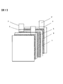
- FIG. 1 is an exploded perspective view of a laminated cell type lithium ion secondary battery.
- FIG. 2 is a diagram illustrating the configuration of the stacked electrode group.
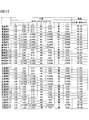
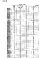
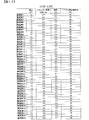
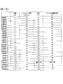
- FIG. 3 is a view showing positive electrode active materials and negative electrode active materials of Examples 1 to 15 and Comparative Examples 1 to 16.
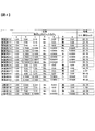
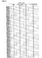
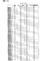
- FIG. 4 is a diagram showing positive electrode active materials and negative electrode active materials of Examples 16 to 30 and Comparative Examples 17 to 20.
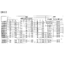
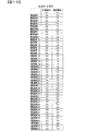
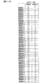
- FIG. 5 is a diagram showing the positive electrode active material and the negative electrode active material of Examples 31 to 40 and Comparative Examples 21 and 22.
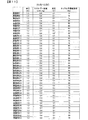
- FIG. 6 is a diagram showing positive electrode active materials and negative electrode active materials of Examples 41 to 43 and Comparative Examples 22 and 23.
- FIG. 7 is a diagram showing test results (capacity, energy density, internal resistance, cycle capacity maintenance rate) when the upper limit voltage is 4.2V and the lower limit voltage is 2.0V.
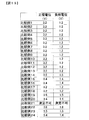
- FIG. 8 is a diagram showing test results (positive electrode potential, negative electrode potential) when the upper limit voltage is 4.2V and the lower limit voltage is 2.0V.
- FIG. 9 is a diagram showing test results (capacity, energy density, internal resistance, cycle capacity retention rate) when the upper limit voltage is 4.2V and the lower limit voltage is 1.5V.
- FIG. 10 is a diagram showing test results (positive electrode potential, negative electrode potential) when the upper limit voltage is 4.2V and the lower limit voltage is 1.5V.
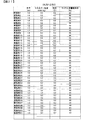
- FIG. 11 is a diagram showing test results (capacity, energy density, internal resistance, cycle capacity retention rate) when the upper limit voltage is 4.4V and the lower limit voltage is 2.0V.
- FIG. 12 is a diagram showing test results (positive electrode potential, negative electrode potential) when the upper limit voltage is 4.2V and the lower limit voltage is 2.0V.
- FIG. 13 is a diagram showing test results (capacity, energy density, internal resistance, cycle capacity maintenance ratio) when the upper limit voltage is 4.5V and the lower limit voltage is 1.5V.
- FIG. 14 is a diagram showing test results (capacity, energy density, internal resistance, cycle capacity maintenance rate) when the upper limit voltage is 4.1V and the lower limit voltage is 1.5V.
- FIG. 15 is a diagram showing test results (capacity, energy density, internal resistance, cycle capacity maintenance ratio) when the upper limit voltage is 4.0V and the lower limit voltage is 1.5V.
- FIG. 16 is a diagram showing test results (positive electrode potential, negative electrode potential) when the upper limit voltage is 4.0V and the lower limit voltage is 1.5V.
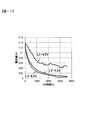
- FIG. 17 is a diagram showing a current decay curve during constant voltage charging.
- FIG. 18 is a diagram showing test results (capacity, energy density, internal resistance, cycle capacity maintenance ratio) of the comparative example.
- FIG. 19 is a diagram showing test results (positive electrode potential, negative electrode potential) of a comparative example.
- FIG. 20 is a diagram illustrating a battery system.
- FIG. 21 is a diagram showing test results (capacity, energy density, internal resistance, cycle capacity maintenance rate) when the upper limit voltage is 4.2V and the lower limit voltage is 2.5V.
- FIG. 1 and 2 are schematic views showing a schematic configuration of a lithium ion secondary battery in the present embodiment.
- FIG. 1 is an exploded perspective view of a laminated cell type lithium ion secondary battery.
- the laminate cell 11 is manufactured by sandwiching the laminated electrode group 9 between the laminate films 8 and 10 and then sealing the peripheral portions of the laminate films 8 and 10 by heat welding to each other.
- FIG. 2 is a diagram showing the configuration of the stacked electrode group 9.
- the laminated electrode group 9 has a configuration in which a plurality of plate-like positive electrodes 5 and a plurality of plate-like negative electrodes 6 are laminated via separators 7, respectively.
- the compositions of the positive electrode active materials of the plurality of positive electrodes 5 constituting one stacked electrode group 9 are all the same.
- the compositions of the negative electrode active materials of the plurality of negative electrodes 6 constituting one stacked electrode group 9 are all the same.
- the separator 7 is made of a material that blocks the movement of lithium ions due to thermal contraction when the lithium ion secondary battery generates heat for some reason.
- polyolefin can be used.
- Polyolefin is a chain polymer material represented by polyethylene and polypropylene. In Examples 1 to 8 described later, a composite material of polyethylene and polypropylene is used as the separator.
- polyolefin contain a heat resistant resin.
- the heat resistant resin polyamide, polyamideimide, polyimide, polysulfone, polyethersulfone, polyphenylsulfone, polyacrylonitrile, or the like is used.
- the inorganic filler layer is made of a material containing at least one of SiO 2 , Al 2 O 3 , montmorillonite, mica, ZnO, TiO 2 , BaTiO 3 , and ZrO 2 . From the viewpoint of cost and performance, SiO 2 or Al 2 O 3 is preferable.
- the positive electrode uncoated portions 3 of the plurality of positive electrodes 5 constituting the stacked electrode group 9 are bundled together and ultrasonically welded to the positive electrode terminal 1.
- the negative electrode uncoated portions 4 of the plurality of negative electrodes 6 are also bundled together and ultrasonically welded to the negative electrode terminal 2.
- Electrode welding is not limited to ultrasonic welding, and resistance welding or the like may be used.
- a heat welding resin may be applied in advance or attached to a portion where the positive electrode terminal 1 and the negative electrode terminal 2 are sealed.
- the laminated electrode group 9 formed as described above is housed in laminated films 8 and 10 as shown in FIG. 1 to produce a laminated cell type lithium ion secondary battery.
- laminated films 8 and 10 in order to provide a liquid injection port for injecting the electrolytic solution into the laminate cell, three sides excluding one side as the liquid injection port are thermally welded. And after injecting electrolyte solution into a lamination cell from an injection port, it heat seals and seals this one side in a vacuum.
- the thermal welding is adjusted so that the thermal welding strength of one side used as the liquid injection port is weaker than the thermal welding strength of the other three sides. This is because when a gas is generated in the laminate cell with charging / discharging, the gas discharge valve has an effect on one side where the thermal welding strength is weak.
- a thin part may be provided in a part of the laminate film 8, and gas may be exhausted from this thin part.
- EC ethylene carbonate
- EMC ethyl methyl carbonate
- the positive electrode active material and the negative electrode active material have the following configurations.
- an active material represented by the general formula Li a Ni b Co c Ad Be O 2 was used as the positive electrode active material.
- a, b, c, d, e, and A and B are 1.0 ⁇ a ⁇ 1.1, 0.50 ⁇ b ⁇ 0.90, 0.05 ⁇ c + d ⁇ 0.5, 0 ⁇ e ⁇ 0.005 is satisfied, A includes at least one of Mn and Al, and B includes at least one of Mg, Mo, W, and Zr.
- the cycle characteristics are significantly deteriorated only by LiNiO 2 , and therefore, the deterioration of the cycle characteristics is suppressed by using Co, Al, and Mn in the active material. Further, in order to further improve the cycle characteristics, substitution with Mg, Mo, W, and Zr is performed.
- the use of the active material for the positive electrode significantly increases the internal resistance at a positive electrode potential of less than 3.3V. Further, it has also been found that when the substitution with Mg, Mo, W, Zr is performed, the internal resistance is further increased at a positive electrode potential of less than 3.3V. Note that the amount e of the substitution element is optimal if it falls outside the above range, because the shape of the discharge curve changes and the initial discharge capacity is greatly reduced.
- the active material of the negative electrode in order not to use a remarkably high internal resistance of positive electrode potential of 3.5 V or less, it is made of graphite and Si alloy, and the mass ratio of graphite and Si alloy (ie, graphite mass / Si alloy mass). ) Is 0.67 or more and 32.3 or less.
- an active material made of graphite and SiOx and having a mass ratio of graphite to SiOx (graphite mass / SiOx mass) of 1.5 or more and 32.3 or less was used.
- the positive electrode active material used for the lithium ion secondary battery according to the present invention is represented by Li a Ni b Co c Ad Be O 2 .
- a, b, c, d, e, and A and B are 1.0 ⁇ a ⁇ 1.1, 0.50 ⁇ b ⁇ 0.90, 0.05 ⁇ c + d ⁇ 0.5, 0 ⁇ . e ⁇ 0.002 is satisfied,
- A includes one or more of Mn or Al, and B includes one or more of Mg, Mo, W, and Zr.
- nickel oxide, cobalt oxide, (manganese dioxide, aluminum oxide, magnesium oxide, molybdenum oxide, tungsten oxide, titanium oxide) is used as a raw material, and after weighing to a predetermined atomic ratio, pure water is added. In addition, a slurry was obtained.
- the slurry was pulverized with a bead mill until the average particle size became 0.2 ⁇ m.
- the polyvinyl alcohol (PVA) solution was added to this slurry in an amount of 1 wt% in terms of solid content ratio, further mixed for 1 hour, and granulated and dried by a spray dryer.
- Li: (NiCoAB) ratio was (1.0 or more and less than 1.1): 1.
- this powder was fired at 850 ° C. for 10 hours to have a crystal having a layered structure, and then pulverized to obtain a positive electrode active material.
- coarse particles having a particle size of 30 ⁇ m or more were removed by classification, and then used for electrode production.
- the method for manufacturing the positive electrode active material in this embodiment is not limited to the above method, and other methods such as a coprecipitation method may be used.
- the mixing ratio of the respective raw materials was changed to produce positive electrode active materials having different compositions.
- the compositions of the positive electrode active materials are shown as Examples 1 to 15 in FIG. 3 and Examples 16 to 30 in FIG.
- B described that it was substituted equally with respect to another transition metal, since it is a very small amount, it is unknown and is described as an assumption to the last.
- the positive electrode is configured by forming a coating layer of a positive electrode active material mixture containing a positive electrode active material on both surfaces of an aluminum foil as a positive electrode current collector.
- a positive electrode active material mixture in which a positive electrode active material, a binder (binder), and a conductive additive are dispersed in a solvent is prepared. Apply to the surface of the electrical body.
- Polyvinylidene fluoride hereinafter referred to as PVDF
- a carbon material was used as the conductive assistant.
- the mass ratio of the positive electrode active material, the binder, and the conductive material was 90: 5: 5.
- NMP N-methylpyrrolidone
- the coating amount of the positive electrode active material mixture on the positive electrode current collector was 240 g / m 2 .
- the density of the positive electrode active material mixture layer was 3.0 g / cm 3 by a roll press device. A roll press was performed. A positive electrode was produced by the process described above.
- the positive electrode uncoated part 3 where the positive electrode active material mixture is not applied is formed on a part of the positive electrode current collector, and the aluminum foil is exposed in this part.
- the negative electrode active material used in the lithium ion secondary battery according to the present invention is composed of a mixture of natural graphite and Si alloy or a mixture of natural graphite and SiO.
- the Si alloy is usually in a state where fine particles of metal silicon (Si) (particle size of about 10 nm) are dispersed in each particle of other metal elements, or other metal elements are each of Si. It is in a state of being dispersed in the particles.
- Other metal elements may be used as long as they contain at least one of Al, Ni, Cu, Fe, Ti, and Mn.
- the Si alloy is produced by mechanically synthesizing by a mechanical alloy method or by heating and cooling a mixture of Si particles and other metal elements. This time, it was synthesized by the mechanical alloy method.
- the composition of the Si alloy is preferably such that the atomic ratio of Si to another metal element is 50:50 to 90:10, more preferably 60:40 to 80:20.
- Silicon oxide is normally in a state where fine particles of metal silicon (Si) (particle size of about 10 nm) are dispersed in each particle of silicon dioxide (SiO 2 ).
- the production of silicon oxide is performed by heating a mixture of silicon dioxide particles and metal silicon particles to generate silicon monoxide gas, which is cooled to precipitate amorphous silicon oxide particles.
- the amorphous silicon oxide particles are represented by the general formula SiOx.
- the ratio of oxygen in the silicon oxide particles can be increased by oxidizing the silicon oxide particles obtained in the above process by heat treatment. That is, the value of x can be increased.
- the negative electrode is configured by forming a coating layer of a negative electrode active material mixture containing a negative electrode active material on both surfaces of a copper foil as a negative electrode current collector.
- a negative electrode active material mixture a negative electrode active material in which a Si alloy particle or SiOx particle as a negative electrode active material, a natural graphite particle, and a binder and a conductive additive are dispersed in a solvent.
- a mixture is prepared and applied to the surface of the negative electrode current collector.
- Polyamideimide was used as the binder, and acetylene black was used as the conductive auxiliary.
- polyamide imide may be polyimide, polyamide, or one containing one or more of these.
- the mixing amount of Si alloy particles or SiOx particles is 20 wt% or less, SBR, PVDF, an acrylic binder may be used, or they may be mixed with polyamideimide.
- the mass ratio of the negative electrode active material, the conductive material, and the binder was 93: 2: 5. Further, NMP was used as a solvent, and the viscosity was adjusted according to the amount.
- the mixing ratio of natural graphite particles and Si alloy particles in the negative electrode active material is preferably such that the mass ratio of natural graphite particles and Si alloy particles is in the range of 40:60 to 97: 3. That is, the value of natural graphite mass / Si alloy mass is preferably in the range of 0.67 to 32.3.
- the mixing ratio of natural graphite particles and silicon oxide particles is preferably such that the mass ratio of natural graphite particles and silicon oxide particles is in the range of 60:40 to 97: 3. That is, the value of the mass of natural graphite / mass of silicon oxide is preferably in the range of 1.5 to 32.3.
- This negative electrode active material mixture was applied to the surface of the negative electrode current collector to form a coating layer of the negative electrode active material mixture.
- the amount of the negative electrode active material mixture applied to the negative electrode current collector was adjusted so that the positive electrode capacity and the negative electrode capacity were equal.
- After the coating layer formed on the surface of the negative electrode current collector was dried, it was roll-pressed by a roll press device so that the density of the negative electrode active material mixture layer was 2.3 g / cm 3 .
- it dried at 250 degreeC.
- FIG. 2 shows the structure of the negative electrode produced. In the negative electrode 6, the negative electrode uncoated portion 4 where the negative electrode active material mixture is not applied is formed on a part of the negative electrode current collector, and the copper foil is exposed at this portion.
- the negative electrode active material When producing the negative electrode active material, the negative electrode was produced by changing the mixing ratio of natural graphite particles and Si alloy particles or SiO particles and the composition of the Si alloy.
- the Si alloy particles and the SiO particles used this time were coated with carbon on the surface, and the weight of each particle was 15 wt% with respect to the particles.
- the carbon coating amount is desirably 5 wt% or more and 30 wt% or less, and more desirably 10 wt% or more and 20 wt% or less.
- the electrical conductivity is substantially equal to that of graphite.
- a stacked electrode group was constructed using the positive electrode and the negative electrode produced by the above-described steps.
- the combinations of positive electrode and negative electrode compositions used are shown in FIGS.
- the lithium ion secondary battery (laminated cell) was charged with a constant voltage and constant current of voltage 4.2 V and current of 300 mA for 5 hours, and then discharged with a final voltage of 2.0 V and constant current of 300 mA. It was.
- the initial discharge capacity at this time was defined as the discharge capacity of each lithium ion secondary battery.
- the energy of the lithium ion secondary battery is the product of the discharge capacity and the average voltage, and the energy density was determined by dividing the energy by the mass of the lithium ion secondary battery.
- the internal resistance of the lithium ion secondary battery was obtained by charging from a voltage of 2.0 V at a current of 1 A for 10 seconds, and dividing the voltage change at this time by the current of 1 A.
- FIG. 7 shows the discharge capacity, energy density, and internal resistance. In the test, two cells were prepared, and the average value of the test results of the two cells was taken.
- FIG. 8 shows the discharge potentials of the positive electrode and the negative electrode during discharge.
- the lithium ion secondary batteries of Examples 1 to 43 have a discharge capacity of 1.1 to 1.2 Ah and an energy density of 0.8. It shows 3 kWh / kg and an internal resistance of 0.2 to 0.3 ⁇ . Further, as can be seen from FIG. 8, the voltage of the positive electrode during 2.0 V discharge is 3.4 V or higher.
- the active material of the positive electrode is represented by the general formula Li a Ni b Co c A d Be O 2 , A includes at least one of Mn and Al, and B includes Mg, Mo, An active material containing at least one of W and Zr is used, and a, b, c, d, and e in the formula are 1.0 ⁇ a ⁇ 1.1 and 0.50 ⁇ b ⁇ 0.90. 0.05 ⁇ c + d ⁇ 0.5 and 0 ⁇ e ⁇ 0.005 are satisfied.
- Examples 1 to 15 and 31 to 40 shown in FIGS. 3 and 5 are cases where an active material containing graphite and a Si alloy is used as the negative electrode active material.
- Examples 16 to 30 and 41 to 43 shown in FIGS. 4 and 6 are cases where an active material containing graphite and SiOx is used as the negative electrode active material, and the mass ratio of graphite to SiOx is 1.5 to 32. The case of 3 or less is shown.
- FIGS. 9 to 16 show the test results when the same tests as those described above were performed while changing the upper limit voltage and the lower limit voltage.
- 9 and 10 show the test results when the upper limit voltage is 4.2V and the lower limit voltage is 1.5V.
- the discharge capacity is 1.1 to 1.2 Ah
- the energy density is 0.3 kWh / kg
- the internal resistance is 0.2 to 0.3 ⁇ .
- the negative electrode potential becomes 2.0 V or more at the lower limit voltage of 1.5 V, lowering the lower limit voltage approaches the elution potential of copper at the negative electrode. This is the lower limit value of the lithium secondary battery of the embodiment.
- FIG. 21 shows the test results when the upper limit voltage is 4.2V and the lower limit voltage is 2.5V.
- Examples 1 to 41 are described.
- the energy density is lowered to 0.2 kWh / kg as compared with the cases shown in FIGS.
- the capacity is released at the high potential of the negative electrode (that is, the low voltage of the battery). For this reason, when the lower limit voltage is as high as 2.5 V, the capacity is small and is greatly reflected in the energy density.
- 11 and 12 show the test results when the upper limit voltage is 4.4V and the lower limit voltage is 2.0V. Compared with the case of the upper limit voltage of 4.2 V and the lower limit voltage of 2.0 V in FIGS. 7 and 8, the cycle characteristics were the same, the energy density was improved, and the internal resistance could be reduced. This is presumably because the potential of the positive electrode was increased by 0.05V.
- FIG. 13 shows the test results when the upper limit voltage is 4.5V and the lower limit voltage is 1.5V. In this case, it was found that the internal resistance was increased and the cycle characteristics were significantly deteriorated. This is considered to be due to the decomposition of the electrolytic solution.
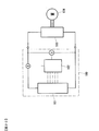
- a line L1 in FIG. 17 shows a current attenuation curve when constant voltage charging is performed at 4.5 V in the first embodiment. Lines L2 and L3 indicate current decay curves when constant voltage charging is performed at 4.3 V and 4.4 V, respectively.
- Figures 14 to 16 show the test results when the upper limit voltage is lowered below 4.2V.
- FIG. 14 shows the test results when the upper limit voltage is 4.1V and the lower limit voltage is 1.5V.
- 15 and 16 show the test results when the upper limit voltage is 4.0V and the lower limit voltage is 1.5V.
- the cycle characteristics and the internal resistance are the same as those of the upper limit voltage of 4.2 V and the lower limit voltage of 2.0 V shown in FIGS.
- the energy density is slightly higher.
- the upper limit voltage is 4.0 V and the lower limit voltage is 1.5 V (FIGS. 15 and 16)
- the cycle characteristics are the same, but the energy density is small.
- the positive electrode potential is as low as 3.2 V, the internal resistance is also as large as 0.3 ⁇ .
- the upper limit voltage is preferably 4.1 V or higher and 4.4 V or lower.
- Comparative Examples 1 to 24 in comparison with Examples 1 to 43.
- Comparative Examples 1 to 16, 21 and 22 correspond to Examples 1 to 15 and 31 to 40, in which an active material containing graphite and a Si alloy is used as the negative electrode active material.
- Comparative Examples 17 to 20, 23 and 24 correspond to Examples 16 to 30 and 41 to 43, and are cases where an active material containing graphite and SiOx is used as the negative electrode active material.
- Comparative Examples 1 to 11 are cases where the ratio of the mass of graphite to the mass of the Si alloy deviates from the range in the present embodiment (0.67 or more and 32.3 or less).
- the composition of the positive electrode is different, and the specification is a low Ni-containing positive electrode.
- Comparative Example 13 is an example in which the ratio of the mass of graphite to the mass of the Si alloy is out of the range, the Si alloy content is 1 wt%, and the Si alloy content is low.
- Comparative Example 14 is a case where the content of the Si alloy is large (70 wt%).
- Comparative Example 15 shows a case where the element substitution amount e of the positive electrode is out of the range.
- Comparative Example 16 is a case where the positive electrode is LiNiO 2 .
- the negative electrode active material in Comparative Examples 12 to 15 is an active material containing graphite and SiOx.
- the comparative example 21 of FIG. 5 is a case where the atomic ratio of Si and another element in the Si alloy active material is as low as 10:90.
- Comparative Example 22 is a case where the atomic ratio between Si and other elements in the Si alloy active material is as high as 95: 5.
- the corresponding atomic ratios of Examples 31 to 40 are 70:30 (Examples 31 to 38), 50:50 (Example 39), and 90:10 (Example 40).
- Comparative Examples 1 to 24 were also tested in the same manner as in the example with an upper limit voltage of 4.2 V and a lower limit voltage of 2.0 V. 18 and 19 show the test results.
- the negative electrode active material is the same as that of the present embodiment, but a comparative example in which the positive electrode active material is different from the present embodiment will be described.
- Comparative Examples 12 and 17 since the positive electrode has a specification of a low Ni-containing positive electrode as compared with the present embodiment, the internal resistance is kept low, but the energy density is low.
- Comparative Examples 15 and 20 are cases in which the element substitution amount e in the positive electrode active material is large and deviates from the range of this embodiment (0 ⁇ e ⁇ 0.005). Since the substituted element is not a transition metal, it has been found that the capacity is greatly reduced and the energy density is lowered.
- Comparative Example 16 since the positive electrode active material is LiNiO 2 , the cycle characteristics are poor.
- the positive electrode active material is the same as that of the present embodiment, a comparative example in which the negative electrode active material is different from the present embodiment will be described.
- the negative electrode active material has a specification that does not include Si alloy or SiOx, and therefore has a low energy density. Furthermore, since the positive electrode operating potential was less than 3.3 V, the result that the internal resistance was increased was obtained.
- Comparative Example 13 is when (graphite mass) / (Si alloy mass) is larger than 32.3
- Comparative Example 18 is when (graphite mass) / (SiO mass) is larger than 32.3.
- the positive electrode operating potential was less than 3.3 V, and the result that the internal resistance was high was obtained.
- Comparative Example 14 is a case where (graphite mass) / (Si alloy mass) is smaller than 0.67
- Comparative Example 19 is a case where (graphite mass) / (SiO mass) is smaller than 1.5. That is, the amount of Si alloy or SiO is larger than the range of the present embodiment, and if the amount exceeds this range, the characteristics of Si alloy and SiO are reflected rather than the characteristics of graphite, and the cycle characteristics are deteriorated. I found out that
- Comparative Example 21 the atomic ratio between Si and other elements in the Si alloy active material is as low as 10:90. For this reason, it was found that the amount of silicon fine particles in the active material was too small, and lithium ions could not move between Si and were not charged / discharged. Conversely, Comparative Example 22 is a case where the atomic ratio between Si and other elements in the Si alloy active material is as high as 95: 5, and it cannot be alloyed to suppress the expansion and contraction of Si. Since the conductive network is destroyed due to the expansion and contraction, the cycle characteristics are greatly deteriorated, and it cannot be used as a lithium ion secondary battery.
- the atomic ratio between the Si element and the other elements in the composition formula of the Si alloy is set in the range of 50:50 to 90:10. It is preferable to do this. More preferably, the range is from 60:40 to 80:20.
- the ratio of oxygen in the silicon oxide particles is increased by oxidizing the silicon oxide particles by heat treatment, the ratio of silicon dioxide generated by the disproportionation reaction increases as x increases.
- silicon dioxide is inactive, when such silicon oxide particles are used as the negative electrode active material of a lithium ion secondary battery, the irreversible capacity is increased, and the energy density tends to decrease as x increases. For this reason, it is more preferable to satisfy 1.0 ⁇ x ⁇ 1.2 in which x is kept smaller than the above range.
- the active material of the positive electrode includes the general formula Li a Ni b Co c Ad Be O 2 (where a, b, c, d, e and A, B are 1.0 ⁇ a ⁇ 1.1, 0.50 ⁇ b ⁇ 0.90, 0.05 ⁇ c + d ⁇ 0.5, 0 ⁇ e ⁇ 0.005, A includes at least one of Mn and Al, and B is Mg , Including at least one of Mo, W, and Zr), it is possible to increase the energy density of the battery.
- the active material of the negative electrode any one of the first active material containing graphite and Si alloy and the second active material containing graphite and SiOx is used.
- the ratio (D / E) of the mass D of the graphite to the mass E of the Si alloy is 0.67 ⁇ (D / E) ⁇ 32.3
- the mass F of the graphite and the mass of SiOx The ratio (F / G) with G is set to 1.5 ⁇ (F / G) ⁇ 32.3.
- the lithium ion secondary battery of the present embodiment has a use lower limit voltage of 1.5 V to 2.0 V and a use upper limit voltage of 4.1 V to 4 V.
- a use lower limit voltage of 1.5 V to 2.0 V and a use upper limit voltage of 4.1 V to 4 V.
- the voltage By setting the voltage to 0.4 V or less, a remarkably high internal resistance at a low positive electrode potential is not used, and a high energy density and a low internal resistance are combined.
- FIG. 20 is a diagram showing a battery system 100 using the lithium ion secondary battery of the present embodiment.
- the battery system 100 includes an assembled battery 101 and a battery control device 102 that controls the charge / discharge state of the assembled battery 101.
- the example shown in FIG. 20 shows a case where the present invention is applied to an electric vehicle such as an electric vehicle, and electric power is supplied from the battery system 100 to the motor 104 via the inverter device 103. During the braking operation of the vehicle, the assembled battery 101 is charged with regenerative power.
- the assembled battery 101 is obtained by connecting a plurality of the above-described lithium secondary batteries (laminate cells 11). Data such as the cell voltage value of each lithium ion secondary battery constituting the assembled battery 101, the total voltage value of the assembled battery 101, the current value of the assembled battery 101, and the battery temperature are input to the battery control device 102. Based on the data, the battery control device 102 sets the lithium ion secondary battery so that the use lower limit voltage is 1.5V to 2.0V and the use upper limit voltage is 4.1V to 4.4V. The charging / discharging of the battery 101 is controlled.
- the mass ratio (H / J) between the mass H of graphite and the mass J of Si alloy in the first active material containing graphite and Si alloy is 0.67 ⁇ (H / J) ⁇ 4, and graphite and SiOx.
- the mass ratio (K / L) of the mass K of graphite and the mass L of Si alloy in the second active material containing 1.5 ⁇ (K / L) ⁇ 4 the negative electrode expands and contracts. become prominent. Therefore, in order to ensure sufficient binding strength, it is preferable that the binder of the negative electrode contains at least one of polyamideimide, polyimide, and polyamide.
- the lithium ion secondary battery is in the form of a laminated laminate cell.
- the present invention can also be applied to lithium-in secondary batteries having other configurations.
- the present invention can be applied to a wound structure or a metal can.
Landscapes
- Chemical & Material Sciences (AREA)
- Chemical Kinetics & Catalysis (AREA)
- Electrochemistry (AREA)
- General Chemical & Material Sciences (AREA)
- Engineering & Computer Science (AREA)
- Inorganic Chemistry (AREA)
- Manufacturing & Machinery (AREA)
- Secondary Cells (AREA)
- Materials Engineering (AREA)
- Battery Electrode And Active Subsutance (AREA)
Abstract
本発明は、エネルギー密度が高く、かつ、内部抵抗の低いリチウムイオン二次電池を提供する。本発明のリチウムイオン二次電池の正極(5)の活物質は、一般式LiaNibCocAdBeO2で表され(式中、a、b、c、d、eおよびA,Bは、1.0≦a≦1.1、0.50≦b≦0.90、0.05≦c+d≦0.5、0≦e≦0.005を満たし、AはMnおよびAlの少なくとも一方を含み、BはMg、Mo、W、Zrの少なくとも一つを含む)、負極(6)は、黒鉛とSi合金とを含む第1活物質、および、黒鉛とSiOxとを含む第2活物質のいずれか一方を有し、第1活物質における黒鉛の質量DとSi合金の質量Eとの比(D/E)は0.67≦(D/E)≦32.3であり、第2活物質における黒鉛の質量FとSiOxの質量Gとの比(F/G)は1.5≦(F/G)≦32.3である。
Description
本発明は、リチウムイオン二次電池および電池システムに関する。
近年、地球温暖化や化石燃料枯渇の問題から、エネルギー消費の少ない電気自動車(EV)が各自動車メーカーにより開発されている。電気自動車の電源としては、エネルギー密度が高いリチウムイオン二次電池が求められているが、現状では十分なエネルギー密度を有するリチウムイオン二次電池は得られていない。
高いエネルギー密度のリチウムイオン二次電池を実現する正極活物質として、LiNiO2が期待されている。
特許文献1には、LiNiO2の課題の一つであるサイクル時の界面抵抗増加を抑制するために、LiNixMyO2(但し、MはAl,Mn,Fe,Ni,Co,Cr,Ti,Zn,P,Bから選ばれる少なくとも一種の元素を表し、xは0<x≦1、yは0≦y<1である)で表される複合酸化物粒子の表面を、Co,Al,Mnで被覆処理することが記載されている。
特許文献2には、酸化ケイ素と炭素質材料を原材料からなる複合体による負極活物質を用いてリチウムイオン二次電池を構成することで、高容量とサイクル特性の低下抑制が実現されることが記載されている。
特許文献3には、Si合金と炭素質材料の複合体による負極活物質を用いてリチウムイオン二次電池を構成することで、高容量とサイクル特性の低下抑制が実現されることが記載されている。
しかしながら、LiNiO2正極や、SiOおよびSi合金を含有する負極に対して、上述のような技術的な改良が種々行われているが、高いエネルギー密度と低い内部抵抗を併せ持つリチウムイオン二次電池は実現されていない。
本発明に係るリチウムイオン二次電池は、正極と負極と電解質とを有するリチウムイオン二次電池であって、前記正極の活物質は、一般式LiaNibCocAdBeO2で表され
(式中、a、b、c、d、eおよびA,Bは、1.0≦a≦1.1、0.50≦b≦0.90、0.05≦c+d≦0.5、0≦e≦0.005を満たし、AはMnおよびAlの少なくとも一方を含み、BはMg、Mo、W、Zrの少なくとも一つを含む)、前記負極は、黒鉛とSi合金とを含む第1活物質、および、黒鉛とSiOxとを含む第2活物質のいずれか一方を有し、前記第1活物質における黒鉛の質量DとSi合金の質量Eとの比(D/E)は0.67≦(D/E)≦32.3であり、前記第2活物質における黒鉛の質量FとSiOxの質量Gとの比(F/G)は1.5≦(F/G)≦32.3である。
(式中、a、b、c、d、eおよびA,Bは、1.0≦a≦1.1、0.50≦b≦0.90、0.05≦c+d≦0.5、0≦e≦0.005を満たし、AはMnおよびAlの少なくとも一方を含み、BはMg、Mo、W、Zrの少なくとも一つを含む)、前記負極は、黒鉛とSi合金とを含む第1活物質、および、黒鉛とSiOxとを含む第2活物質のいずれか一方を有し、前記第1活物質における黒鉛の質量DとSi合金の質量Eとの比(D/E)は0.67≦(D/E)≦32.3であり、前記第2活物質における黒鉛の質量FとSiOxの質量Gとの比(F/G)は1.5≦(F/G)≦32.3である。
本発明によれば、エネルギー密度が高く、かつ、内部抵抗の低いリチウムイオン二次電池を提供できる。
以下、図を参照して本発明を実施するための形態について説明する。図1,2は、本実施の形態におけるリチウムイオン二次電池の概略構成を示す模式図である。図1は、ラミネートセル型のリチウムイオン二次電池の分解斜視図を示す。ラミネートセル11は、積層型電極群9をラミネートフィルム8,10で挟んだ後、ラミネートフィルム8,10の周縁部を互いに熱溶着させて封止することにより作製される。
図2は、積層型電極群9の構成を示す図である。積層型電極群9は、複数の板状の正極5と複数の板状の負極6とがそれぞれセパレータ7を介して積層された構成となっている。一つの積層型電極群9を構成する複数の正極5の正極活物質の組成は全て同じものである。同様に、一つの積層型電極群9を構成する複数の負極6の負極活物質の組成も全て同じものである。
セパレータ7としては、リチウムイオン二次電池が何らかの原因により発熱した際に、熱収縮によりリチウムイオンの移動を遮断する材料が用いられる。例えば、ポリオレフィンを用いることができる。ポリオレフィンは、ポリエチレンやポリプロピレンを代表とする鎖状の高分子材料である。後述する実施例1~8では、セパレータとして、ポリエチレンとポリプロピレンの複合材が用いられている。
なお、セパレータに用いられる他の材料としては、ポリオレフィンに耐熱性樹脂を含有させたものがある。耐熱性樹脂には、ポリアミド、ポリアミドイミド、ポリイミド、ポリスルホン、ポリエーテルスルホン、ポリフェニルスルホン、ポリアクリロニトリル等が用いられる。さらに、セパレータの片面もしくは両面に無機フィラー層を形成してもよい。無機フィラー層は、SiO2、Al2O3、モンモリロナイト、雲母、ZnO、TiO2、BaTiO3、ZrO2のうちの少なくとも1種類を含む材料により構成される。コストや性能の観点からは、SiO2またはAl2O3が好ましい。
積層型電極群9を構成する複数の正極5の正極未塗工部3は、互いに束ねられて正極端子1に超音波溶接される。同様に、複数の負極6の負極未塗工部4も、互いに束ねられて負極端子2に超音波溶接される。電極の溶接は超音波溶接に限らず、抵抗溶接等を用いてもよい。また、リチウムイオン二次電池の封止をより確実にするために、正極端子1と負極端子2の封止される箇所に、予め熱溶着樹脂を塗布するか、あるいは取り付けておいてもよい。
上記のようにして形成された積層型電極群9を、図1に示すようにラミネートフィルム8,10に収納してラミネートセル型のリチウムイオン二次電池が作製される。ラミネートフィルム8,10で封止する際には、電解液をラミネートセル内に注入するための注液口を設けるために、注液口とする一辺を除いた三辺を熱溶着する。そして、注液口から電解液をラミネートセル内に注液した後に、この一辺を真空加圧しながら熱溶着を行い封止する。
なお、注液口とする一辺の熱溶着強度が他の三辺の熱溶着強度に比べて弱くなるように、熱溶着を調整する。これは充放電に伴ってラミネートセル内にガスが発生した場合に、熱溶着強度の弱い一辺にガス排出弁の効果を持たせるためである。ガス排出のための手段としては上記の他に、ラミネートフィルム8の一部に薄肉部を設け、この薄肉部からガスが排出されるようにしてもよい。
電解液には有機電解液が用いられる。有機電解液は、電解質として1mol/dm-3のLiPF6を、エチレンカーボネート(EC):エチルメチルカーボネート(EMC)=1:3(vol%)の有機溶媒に溶解させたものである。
電解液としては上記の他に、例えば、エチレンカーボネート、プロピレンカーボネート、ブチレンカーボネート、ジメチルカーボネート、エチルメチルカーボネート、ジエチルカーボネート、γ-ブチロラクトン、γ-バレロラクトン、メチルアセテート、エチルアセテート、メチルプロピオネート、テトラヒドロフラン、2-メチルテトラヒドロフラン、1,2-ジメトキシエタン、1-エトキシ-2-メトキシエタン、3-メチルテトラヒドロフラン、1,2-ジオキサン、1,3-ジオキサン、1,4-ジオキサン、1,3-ジオキソラン、2-メチル-1,3-ジオキソラン、4-メチル-1,3-ジオキソラン等のうちの少なくとも1種以上で構成された非水溶媒に、例えば、LiPF6、LiBF4、LiClO4、LiN(C2F5SO2)2等のうち少なくとも1種以上のリチウム塩を溶解させた有機電解液、あるいはリチウムイオンの伝導性を有する固体電解質、あるいはゲル状電解質、あるいは溶融塩等、既知のものを用いることができる。
本実施の形態では、エネルギー密度が高く、かつ、内部抵抗が低いリチウムイオン二次電池を達成するために、正極活物質および負極活物質を以下のような構成とした。まず、高エネルギー密度化を図るために、正極の活物質として、一般式LiaNibCocAdBeO2で表される活物質を用いた。なお、式中、a、b、c、d、eおよびA,Bは、1.0≦a≦1.1、0.50≦b≦0.90、0.05≦c+d≦0.5、0≦e≦0.005を満たし、AはMnおよびAlの少なくとも一方を含み、BはMg、Mo、W、Zrの少なくとも一つを含む。
従来から知られているように、LiNiO2のみではサイクル特性が著しく悪化するので、上記活物質においてはCo、Al、Mnを用いることでサイクル特性の悪化を抑制するようにした。さらに、よりサイクル特性を向上するため、Mg、Mo、W、Zrによる置換を行っている。
しかしながら、上記活物質を正極に用いることで、正極電位3.3V未満において内部抵抗が著しく増加することを見出した。また、Mg、Mo、W、Zrによる置換を行うと、正極電位3.3V未満において内部抵抗が更に増加することも見出した。なお、置換元素の量eは、上記範囲を外れると放電カーブの形状が変化し、かつ初期放電容量も大幅に減少してしまうので、上記範囲が最適である。
また、負極の活物質としては、正極電位3.5V以下の著しく高い内部抵抗を利用しないために、黒鉛とSi合金からなり、黒鉛とSi合金との質量比(すなわち、黒鉛質量/Si合金質量)が0.67以上、かつ、32.3以下である活物質を用いるようにした。または、黒鉛とSiOxからなり、黒鉛とSiOxとの質量比(黒鉛質量/SiOx質量)が1.5以上、かつ、32.3以下である活物質を用いた。
<正極活物質および正極の作製>
本発明に係るリチウムイオン二次電池に用いる正極活物質は、LiaNibCocAdBeO2で表される。式中、a、b、c、d、eおよびA,Bは、1.0≦a≦1.1、0.50≦b≦0.90、0.05≦c+d≦0.5、0≦e≦0.002を満たし、AはMnまたはAlを1種類以上含む、BはMg、Mo、W、Zrから1種類以上含むものである。
本発明に係るリチウムイオン二次電池に用いる正極活物質は、LiaNibCocAdBeO2で表される。式中、a、b、c、d、eおよびA,Bは、1.0≦a≦1.1、0.50≦b≦0.90、0.05≦c+d≦0.5、0≦e≦0.002を満たし、AはMnまたはAlを1種類以上含む、BはMg、Mo、W、Zrから1種類以上含むものである。
ここでは、原料として、酸化ニッケル,酸化コバルト,(二酸化マンガン,酸化アルミニウム,酸化マグネシウム,酸化モリブテン,酸化タングステン、酸化チタン)を使用し、所定の原子比となるように秤量した後に、純水を加えスラリーとした。
このスラリーを平均粒径が0.2μmとなるまでビーズミルで粉砕した。
このスラリーにポリビニルアルコール(PVA)溶液を固形分比に換算して1wt%添加し、更に1時間混合し、スプレードライヤ-により造粒および乾燥させた。
この造粒粒子に対し、Li:(NiCoAB)比が(1.0以上1.1未満):1となるように水酸化リチウムおよび炭酸リチウムを加えた。
次に、この粉末を850℃で10時間焼成することにより層状構造の結晶を有するものとし、その後、それを解砕して正極活物質を得た。
さらに、分級により粒径30μm以上の粗大粒子を除去した後、電極作製に用いた。
なお、本実施の形態に関する正極活物質の作製方法は、上記の方法に限定されず、共沈法など、他の方法を用いてもよい。
ここでは、正極活物質を作製する際に、前記それぞれの原料の混合比率を変化させて、異なる組成の正極活物質を作製した。それらを、図3に実施例1~15、図4に実施例16~30として正極活物質の組成を示した。なお、Bは、他の遷移金属に対して、均等に置換されているものと記載したが、微少量であるため、不明であり、あくまでも仮定として記載している。
正極は、正極集電体としてのアルミニウム箔の両面に、正極活物質を含む正極活物質合剤の塗工層が形成されて構成される。正極活物質合剤の塗工層を形成するには、正極活物質とバインダ(結着材)と導電助剤とを溶媒中に分散させた正極活物質合剤を作製し、これを正極集電体の表面に塗工する。バインダとしてはポリフッ化ビニリデン(以下、PVDFと記載する)を用い、導電助剤としては炭素材料を用いた。正極活物質、バインダ、および導電材の質量比は90:5:5とした。また、溶媒としてはN-メチルピロリドン(以下、NMPと略記する)を用い、その量により粘度調整を行った。正極集電体への正極活物質合剤の塗工量は240g/m2とした。正極活物質合剤を塗工した正極集電体は、正極活物質合剤の塗工層を乾燥させた後、ロールプレス装置により正極活物質合剤層の密度が3.0g/cm3となるようにロールプレスした。以上説明した工程により正極を作製した。
図2に示す正極5では、正極集電体の一部に正極活物質合剤の塗工されない正極未塗工部3が形成されており、この部分ではアルミニウム箔が露出している。
<負極活物質および負極の作製>
本発明に係るリチウムイオン二次電池に用いる負極活物質は、天然黒鉛とSi合金の混合物または天然黒鉛とSiOの混合物からなる。Si合金は、通常、金属ケイ素(Si)の微細な粒子(粒径10nm程度)が他の金属元素の各粒子中に分散された状態となっているか、または、他の金属元素がSiの各粒子中に分散された状態となっている。他の金属元素は、Al、Ni、Cu、Fe、Ti、Mnのいずれか1種類以上を含むものであれば、構わない。
本発明に係るリチウムイオン二次電池に用いる負極活物質は、天然黒鉛とSi合金の混合物または天然黒鉛とSiOの混合物からなる。Si合金は、通常、金属ケイ素(Si)の微細な粒子(粒径10nm程度)が他の金属元素の各粒子中に分散された状態となっているか、または、他の金属元素がSiの各粒子中に分散された状態となっている。他の金属元素は、Al、Ni、Cu、Fe、Ti、Mnのいずれか1種類以上を含むものであれば、構わない。
Si合金の作製方法としては、メカニカルアロイ法により機械的に合成するか、または、Si粒子と他の金属元素との混合物を加熱および冷却することで得られる。今回は、メカニカルアロイ法により合成した。後述するように、Si合金の組成は、Siと他の金属元素との原子比率が50:50~90:10であるのが望ましく、より望ましくは60:40~80:20である。
酸化ケイ素は、通常、金属ケイ素(Si)の微細な粒子(粒径10nm程度)が二酸化ケイ素(SiO2)の各粒子中に分散された状態となっている。酸化ケイ素の作製は、二酸化ケイ素粒子と金属ケイ素粒子との混合物を加熱して一酸化ケイ素ガスを生成させ、これを冷却して非晶質酸化ケイ素粒子を析出させることで行う。この非晶質酸化ケイ素粒子は一般式SiOxで表される。上記工程で得られた酸化ケイ素粒子を熱処理して酸化させることで酸化ケイ素粒子中の酸素の比率を増加させることができる。即ち、xの値を大きくすることができる。
負極は、負極集電体としての銅箔の両面に、負極活物質を含む負極活物質合剤の塗工層が形成されて構成される。負極活物質合剤の塗工層を形成するには、負極活物質としてのSi合金粒子またはSiOx粒子と、天然黒鉛粒子に加えてバインダと導電助剤とを溶媒中に分散させた負極活物質合剤を作製し、これを負極集電体の表面に塗工する。バインダとしてはポリアミドイミドを用い、導電助剤としてはアセチレンブラックを用いた。
なお、今回、ポリアミドイミドを用いたが、ポリイミド、ポリアミド、もしくはこれらを1種類以上含むものであってもかまわない。さらに、Si合金粒子またはSiOx粒子の混合量が20wt%以下の場合は、SBRやPVDFやアクリル系バインダを用いても構わないし、ポリアミドイミドと混合させても構わない。
負極活物質、導電材、およびバインダの質量比は93:2:5とした。また、溶媒としてはNMPを用い、その量により粘度調整を行った。負極活物質における天然黒鉛粒子とSi合金粒子の混合比は、天然黒鉛粒子とSi合金粒子の質量比を40:60~97:3の範囲とすることが好ましい。即ち、天然黒鉛質量/Si合金質量の値が0.67~32.3の範囲であることが好ましい。また、天然黒鉛粒子と酸化ケイ素粒子の混合比は、天然黒鉛粒子と酸化ケイ素粒子の質量比を60:40~97:3の範囲とすることが好ましい。即ち、天然黒鉛質量/酸化ケイ素質量の値が1.5~32.3の範囲であることが好ましい。
この負極活物質合剤を負極集電体の表面に塗工して負極活物質合剤の塗工層を形成した。負極集電体への負極活物質合剤の塗工量は、正極の容量と負極の容量が等しくなるように調節した。負極集電体の表面に形成した塗工層を乾燥させた後、ロールプレス装置により負極活物質合剤層の密度が2.3g/cm3となるようにロールプレスした。また、ポリアミドイミドを硬化させるために250℃で乾燥した。上記工程により負極を作製した。図2に作製された負極の構成を示す。負極6は、負極集電体の一部に負極活物質合剤の塗工されない負極未塗工部4が形成されており、この部分では銅箔が露出している。
負極活物質を作製する際に、天然黒鉛粒子とSi合金粒子またはSiO粒子の混合比やSi合金の組成を変化させて、負極を作製した。今回用いたSi合金粒子とSiO粒子は、表面に炭素をコートしたものであり、その重量は、それぞれ粒子に対して、炭素量は15wt%のものを用いた。炭素コート量は、5wt%以上30wt%以下が望ましく、より望ましくは、10wt%以上20wt%以下であり、これらであれば電気導電性は黒鉛とほぼ同等となる。
<リチウムイオン二次電池の作製>
上記説明の工程により作製した正極と負極を用いて積層型電極群を構成した。用いた正極と負極の組成の組み合わせは図3~6に示す。
上記説明の工程により作製した正極と負極を用いて積層型電極群を構成した。用いた正極と負極の組成の組み合わせは図3~6に示す。
<放電容量、平均電圧、エネルギー密度、および内部抵抗>
上記のリチウムイオン二次電池(ラミネートセル)に対して、電圧4.2V、電流300mAの定電圧定電流で5時間充電を行った後、終止電圧2.0V、電流300mAの定電流放電を行った。このときの初期の放電容量をそれぞれのリチウムイオン二次電池の放電容量とした。リチウムイオン二次電池のエネルギーは、放電容量と平均電圧の積であり、エネルギー密度は、エネルギーをリチウムイオン二次電池の質量で除算して求めた。リチウムイオン二次電池の内部抵抗は、電圧2.0Vから電流1Aで10秒間充電し、このときの電圧変化を電流1Aで除算して求めた。図7に、放電容量、エネルギー密度、および内部抵抗を示す。試験では、それぞれ2つずつセルを作製し、2つのセルの試験結果の平均値を取った。
上記のリチウムイオン二次電池(ラミネートセル)に対して、電圧4.2V、電流300mAの定電圧定電流で5時間充電を行った後、終止電圧2.0V、電流300mAの定電流放電を行った。このときの初期の放電容量をそれぞれのリチウムイオン二次電池の放電容量とした。リチウムイオン二次電池のエネルギーは、放電容量と平均電圧の積であり、エネルギー密度は、エネルギーをリチウムイオン二次電池の質量で除算して求めた。リチウムイオン二次電池の内部抵抗は、電圧2.0Vから電流1Aで10秒間充電し、このときの電圧変化を電流1Aで除算して求めた。図7に、放電容量、エネルギー密度、および内部抵抗を示す。試験では、それぞれ2つずつセルを作製し、2つのセルの試験結果の平均値を取った。
<サイクル特性>
エネルギーおよび内部抵抗の測定が終わった一方のセルを用いて、サイクル試験した。サイクル試験では、電圧4.2V、電流300mAの定電流充電し、その後、電圧2.0V、電流300mAの定電流放電する試験を100サイクル行う。そして、100サイクル後に、上記同様、電圧4.2V、電流300mAの定電圧定電流で5時間充電を行った後、電圧2.0V、電流300mAの定電流放電を行い、100サイクル後の放電容量を算出した。サイクル容量維持率は、(100サイクル後の放電容量)/(初期の放電容量)×100で算出した。図7の右端の縦列にサイクル容量維持率を記載した。
エネルギーおよび内部抵抗の測定が終わった一方のセルを用いて、サイクル試験した。サイクル試験では、電圧4.2V、電流300mAの定電流充電し、その後、電圧2.0V、電流300mAの定電流放電する試験を100サイクル行う。そして、100サイクル後に、上記同様、電圧4.2V、電流300mAの定電圧定電流で5時間充電を行った後、電圧2.0V、電流300mAの定電流放電を行い、100サイクル後の放電容量を算出した。サイクル容量維持率は、(100サイクル後の放電容量)/(初期の放電容量)×100で算出した。図7の右端の縦列にサイクル容量維持率を記載した。
<正極と負極における放電電位>
エネルギーおよび内部抵抗の測定が終わった他方のセルを用いて、リチウムイオン二次電池を解体して正極および負極を取り出し、リチウム金属参照極を備えた小型テストセルに装着して電圧2.0Vで放電させ、このときの正極および負極の放電電位をそれぞれ測定した。図8に放電時の正極および負極の放電電位を示す。
エネルギーおよび内部抵抗の測定が終わった他方のセルを用いて、リチウムイオン二次電池を解体して正極および負極を取り出し、リチウム金属参照極を備えた小型テストセルに装着して電圧2.0Vで放電させ、このときの正極および負極の放電電位をそれぞれ測定した。図8に放電時の正極および負極の放電電位を示す。
図7(上限電圧4.2V-下限電圧2.0V)の試験結果から分かるように、実施例1~43のリチウムイオン二次電池は、放電容量1.1~1.2Ah、エネルギー密度0.3kWh/kg、内部抵抗0.2~0.3Ωを示している。また、図8から分かるように、2.0V放電時の正極の電圧は3.4V以上を示している。
なお、実施例1~43は、正極の活物質として、一般式LiaNibCocAdBeO2で表され、AはMnおよびAlの少なくとも一方を含み、BはMg、Mo、W、Zrの少なくとも一つを含むような活物質が用いられ、式中のa、b、c、d、eが、1.0≦a≦1.1、0.50≦b≦0.90、0.05≦c+d≦0.5、0≦e≦0.005を満たしているものである。そして、実施例1~43の内、図3,5に示す実施例1~15,31~40は、負極活物質として黒鉛とSi合金とを含む活物質を用いる場合で、黒鉛とSi合金との質量比が0.67以上32.3以下の場合を示す。一方、図4,6に示す実施例16~30,41~43は、負極活物質として黒鉛とSiOxとを含む活物質を用いる場合で、黒鉛とSiOxとの質量比が1.5以上32.3以下の場合を示す。
図9~16は、上述した試験と同様の試験を、上限電圧および下限電圧を変えて実施した場合の試験結果を示したものである。図9,10は、上限電圧4.2V、下限電圧1.5Vの場合の試験結果を示す。この場合も、図7,8の場合と同様に、放電容量1.1~1.2Ah、エネルギー密度0.3kWh/kg、内部抵抗0.2~0.3Ωを示している。また、図10から分かるように、下限電圧1.5Vで負極電位が2.0V以上となることから、これ以上下限電圧を下げると、負極における銅の溶出電位に近づくため、1.5Vが本実施の形態のリチウム二次電池の下限値となる。
また、図21は、上限電圧4.2V、下限電圧2.5Vの場合の試験結果を示す。なお、図21では、実施例1~41について記載した。図21に示すデータでは、図7,9に示す場合と比べた場合、エネルギー密度が0.2kWh/kgと低下している。Si系負極の場合、負極の高電位(つまり電池の低電圧)で容量が放出される。そのため、下限電圧が2.5Vと高い場合には容量が少なく、エネルギー密度に大きく反映される。
図11,12は、上限電圧4.4V、下限電圧2.0Vの場合の試験結果を示す。図7,8の上限電圧4.2V、下限電圧2.0Vの場合と比較すると、サイクル特性は同等で、エネルギー密度は向上し、かつ、内部抵抗の低減も図ることができた。これは、正極の電位が0.05Vだけ高電位化したためであると考えられる。
図13は、上限電圧4.5V、下限電圧1.5Vの場合の試験結果を示す。この場合、内部抵抗は増加し、また、サイクル特性も著しく悪化することがわかった。これは、電解液の分解による影響と考えられる。図17のラインL1は、実施例1において4.5Vで定電圧充電をした際の電流減衰カーブを示す。ラインL2,L3は、それぞれ4.3V,4.4Vで定電圧充電を行った場合の電流減衰カーブを示す。
4.5Vでは定電圧充電時に電流が大きく流れ、かつ、ぶれており、これは電解液の分解を示唆する結果といえる。4.5Vで電解液が酸化分解し、正極表面に液分解由来の被膜をつくるため内部抵抗が増加し、また、電解液の組成が変化することにより、溶媒和するリチウムが減ることでサイクル特性が悪化したものと推察できる。
図14~16は、上限電圧を4.2Vよりも下げた場合の試験結果を示す。図14は、上限電圧4.1V、下限電圧1.5Vの場合の試験結果である。図15,16は、上限電圧4.0V、下限電圧1.5Vの場合の試験結果である。上限電圧4.1V、下限電圧1.5Vの場合(図14)には、図7,8の上限電圧4.2V、下限電圧2.0Vの場合と比較すると、サイクル特性および内部抵抗は同等で、エネルギー密度はやや大きくなっている。また、上限電圧4.0V、下限電圧1.5Vの場合(図15,16)には、サイクル特性は同等であるが、エネルギー密度は小さくなっている。また、正極電位が3.2Vと低くなるため、内部抵抗も0.3Ωと大きくなっている。以上のことから、本実施の形態のリチウム二次電池においては、上限電圧は4.1V以上4.4V以下であることが好ましい。
[実施例と比較例との対比]
図3~6には、実施例1~43に対させて比較例1~24も示している。比較例1~16,21,22は実施例1~15,31~40に対応するもので、負極活物質として黒鉛とSi合金とを含む活物質を用いる場合である。一方、比較例17~20,23,24は実施例16~30,41~43に対応するもので、負極活物質として黒鉛とSiOxとを含む活物質を用いる場合である。
図3~6には、実施例1~43に対させて比較例1~24も示している。比較例1~16,21,22は実施例1~15,31~40に対応するもので、負極活物質として黒鉛とSi合金とを含む活物質を用いる場合である。一方、比較例17~20,23,24は実施例16~30,41~43に対応するもので、負極活物質として黒鉛とSiOxとを含む活物質を用いる場合である。
比較例1~11は、黒鉛の質量とSi合金の質量との比が本実施の形態の場合の範囲(0.67以上32.3以下)から外れる場合である。比較例12は正極の組成が異なり、低Ni含有正極の仕様となっている。比較例13は、黒鉛の質量とSi合金の質量との比が範囲外であって、Si合金の含有量が1wt%であって、Si合金の含有量が少ない例である。逆に、比較例14はSi合金の含有量が多い場合(70wt%)である。比較例15は、正極の元素置換量eが範囲外の場合を示す。比較例16は、正極がLiNiO2の場合である。
図4の比較例17~20は、比較例12~15において負極活物質を黒鉛とSiOxとを含む活物質としたものである。図5の比較例21は、Si合金活物質におけるSiと他の元素との原子比率が10:90と低い場合である。逆に、比較例22は、Si合金活物質におけるSiと他の元素との原子比率が95:5と高い場合である。対応する実施例31~40の原子比率は、70:30(実施例31~38)、50:50(実施例39)、90:10(実施例40)である。
また、図6の比較例23は、SiOxのSi量が多い場合(x=0.5)であって、比較例24はSiOxのSi量が少ない場合(x=1.6)である。これらの比較例1~24に対しても、上限電圧4.2V、下限電圧2.0Vで実施例の場合と同様の試験を行った。図18,19は試験結果である。
まず、負極活物質については本実施の形態と同様であるが、正極活物質が本実施の形態と異なる比較例について説明する。比較例12,17は正極が本実施の形態と比べて低Ni含有正極の仕様となっているので、内部抵抗は低く抑えられているがエネルギー密度が低い。比較例15,20は正極活物質における元素置換量eが大きく、本実施の形態の範囲(0≦e≦0.005)から外れる場合である。置換した元素が遷移金属でないために容量を大きく低減させ、エネルギー密度を下げてしまうことがわかった。比較例16は正極活物質がLiNiO2であるために、サイクル特性が悪い。
次に、正極活物質については本実施の形態と同様であるが、負極活物質が本実施の形態と異なる比較例について説明する。比較例1~11は、負極活物質が本実施の形態の場合と異なりSi合金やSiOxを含まない仕様であるために、エネルギー密度が低い。さらに、正極作動電位が3.3V未満となるために、内部抵抗が高くなるという結果が得られた。
比較例13は(黒鉛質量)/(Si合金質量)が32.3よりも大きい場合で、比較例18は(黒鉛質量)/(SiO質量)が32.3よりも大きい場合である。この場合、本実施形態に比べてSi合金量またはSiO量が少な過ぎるため、負極の放電カーブ変化への影響が小さい。そのため、正極作動電位が3.3V未満となり、内部抵抗が高いという結果が得られた。
比較例14は(黒鉛質量)/(Si合金質量)が0.67よりも小さい場合で、また、比較例19は(黒鉛質量)/(SiO質量)が1.5よりも小さい場合である。すなわち、Si合金量またはSiO量が本実施の形態の範囲よりも多い仕様であり、この範囲を超える量の場合は、黒鉛の特性よりもSi合金やSiOの特性が反映され、サイクル特性を悪化させることがわかった。
比較例21は、Si合金活物質におけるSiと他の元素との原子比率が10:90と低い。そのため、活物質内におけるシリコン微粒子が少なすぎ、Si同士をリチウムイオンが移動できず、充放電されないことがわかった。逆に、比較例22はSi合金活物質におけるSiと他の元素との原子比率が95:5と高い場合であり、合金化してSiの膨張収縮を抑えることができない。その膨張収縮により導電ネットワークが破壊されるため、サイクル特性が大幅に低下し、リチウムイオン二次電池として利用することができない。
実施例31~40および比較例21,22に対する試験結果からも分かるように、Si合金の組成式におけるSi元素と他の元素との原子比率は、50:50から90:10までの範囲に設定するのが好ましい。より望ましくは、60:40から80:20の範囲とするのが良い。
図6の比較例23は、負極活物質に含まれるSiOxがx=0.5の場合である。SiOxは、シリコン微粒子をSiOxが覆うような粒子構造である。x=0.5の場合はシリコン微粒子の比率が高いことを意味しており、図18に示すようにサイクル特性が悪化する。比較例24はx=1.6の場合であり、Si量が少ない仕様である。シリコン微粒子を覆っているSiOxは、Si合金における合金と異なり、SiOx中をリチウムイオンが移動するものと考えられているが、拡散抵抗は高い。つまり、比較例24は、SiOx量が多いために、内部抵抗が高いものと考えられる。これらから、SiOxのxは、1.0≦x<1.6とするのが好ましい。
なお、上述したように、酸化ケイ素粒子を熱処理して酸化させることで酸化ケイ素粒子中の酸素の比率を増加させているので、xが大きくなるほど不均化反応によって発生する二酸化ケイ素の割合が大きくなる。二酸化ケイ素は不活性であるため、このような酸化ケイ素粒子をリチウムイオン二次電池の負極活物質に使用した場合、不可逆容量の増加を引き起こし、xが大きいほどエネルギー密度が下がる傾向となる。そのため、上記範囲よりもxを小さく抑えた1.0≦x<1.2とするのがより好ましい。
以上説明したように、本実施の形態のリチウムイオン二次電池は、正極の活物質に、一般式LiaNibCocAdBeO2(式中、a、b、c、d、eおよびA,Bは、1.0≦
a≦1.1、0.50≦b≦0.90、0.05≦c+d≦0.5、0≦e≦0.005を満たし、AはMnおよびAlの少なくとも一方を含み、BはMg、Mo、W、Zrの少なくとも一つを含む)で表される活物質を用いることにより、電池の高エネルギー密度化が可能となる。
a≦1.1、0.50≦b≦0.90、0.05≦c+d≦0.5、0≦e≦0.005を満たし、AはMnおよびAlの少なくとも一方を含み、BはMg、Mo、W、Zrの少なくとも一つを含む)で表される活物質を用いることにより、電池の高エネルギー密度化が可能となる。
そして、負極の活物質として、黒鉛とSi合金とを含む第1の活物質、および、黒鉛とSiOxとを含む第2の活物質のいずれか一方を使用し、第1の活物質の場合、黒鉛の質量DとSi合金の質量Eとの比(D/E)を0.67≦(D/E)≦32.3とし、第2の活物質の場合、黒鉛の質量FとSiOxの質量Gとの比(F/G)を1.5≦(F/G)≦32.3とする。このような活物質を負極に用いることにより、サイクル特性の低下を防止しつつ、正極電位の過度な低下による内部抵抗の増加を防止することができる。
また、上述した図9~16の試験結果から分かるように、本実施の形態のリチウムイオン二次電池は、利用下限電圧を1.5V以上2.0V以下、利用上限電圧が4.1V以上4.4V以下とすることで、正極電位が低いところにおける著しく高い内部抵抗を利用することがなく、高いエネルギー密度と低い内部抵抗を併せ持つことになる。
図20は、本実施の形態のリチウムイオン二次電池を用いた電池システム100を示す図である。電池システム100は、組電池101と、組電池101の充放電状態を制御する電池制御装置102とを備えている。図20に示す例は、電気自動車等の電動車両に適用した場合を示したものであり、電池システム100からインバータ装置103を介してモータ104に電力が供給される。車両の制動動作時には、回生電力によって組電池101が充電される。
組電池101は、上述したリチウム二次電池(ラミネートセル11)を複数接続したものである。電池制御装置102には、組電池101を構成する各リチウムイオン二次電池のセル電圧値、組電池101の総電圧値、組電池101の電流値、電池温度等のデータが入力される。電池制御装置102は、それらのデータに基づいて、リチウムイオン二次電池の利用下限電圧が1.5V以上2.0V以下、利用上限電圧が4.1V以上4.4V以下となるように、組電池101の充放電を制御する。
さらに、黒鉛とSi合金とを含む第1の活物質における黒鉛の質量HとSi合金の質量Jとの質量比(H/J)が0.67≦(H/J)≦4、黒鉛とSiOxとを含む第2の活物質における黒鉛の質量KとSi合金の質量Lとの質量比(K/L)が1.5≦(K/L)≦4の場合には、負極の膨張収縮が顕著となる。そのため、十分な結着強度を確保するためには、負極のバインダに、ポリアミドイミド、ポリイミド、ポリアミドの少なくとも一つを含むようにするのが好ましい。
以上説明した通り、本発明によれば、高いエネルギー密度と低い内部抵抗を併せ持つサイクル特性に優れたリチウムイオン二次電池を提供できる。
また、実施例では、リチウムイオン二次電池として積層型のラミネートセルの形態としたが、本発明は、それ以外の構成のリチウムイン二次電池にも適用できることは言うまでもない。例えば、捲回構造のものや金属缶に封入されたものに対しても適用可能である。
上記の通り、種々の実施の形態及び変形例について説明したが、本発明はこれらの内容に限定されるものではない。本発明の技術的思想の範囲内で考えられるその他の態様も本発明の範囲内に含まれる。
5…正極、6…負極、7…セパレータ、8,10…ラミネートフィルム、9…積層型電極群、11…ラミネートセル、100…電池システム、101…組電池、102…電池制御装置
Claims (7)
- 正極と負極と電解質とを有するリチウムイオン二次電池であって、
前記正極の活物質は、一般式LiaNibCocAdBeO2で表され(式中、a、b、c、d、eおよびA,Bは、1.0≦a≦1.1、0.50≦b≦0.90、0.05≦c+d≦0.5、0≦e≦0.005を満たし、AはMnおよびAlの少なくとも一方を含み、BはMg、Mo、W、Zrの少なくとも一つを含む)、
前記負極は、黒鉛とSi合金とを含む第1活物質、および、黒鉛とSiOxとを含む第2活物質のいずれか一方を有し、
前記第1活物質における黒鉛の質量DとSi合金の質量Eとの比(D/E)は0.67≦(D/E)≦32.3であり、
前記第2活物質における黒鉛の質量FとSiOxの質量Gとの比(F/G)は1.5≦(F/G)≦32.3である、リチウムイオン二次電池。 - 請求項1に記載のリチウムイオン二次電池において、
前記第1活物質におけるSi合金は、Al、Ni、Cu、Fe、TiおよびMnの少なくとも一つとSiとを含むSi合金であり、該Si合金の組成式におけるSi元素と他の元素との原子比率が50:50から90:10までの範囲に設定されている、リチウムイオン二次電池。 - 請求項1に記載のリチウムイオン二次電池において、
前記第2活物質におけるSiOxはシリコン微粒子と酸化ケイ素とを含み、
前記SiOxにおけるxが1.0≦x<1.6である、リチウムイオン二次電池。 - 請求項1乃至3のいずれかに記載のリチウムイオン二次電池において、
前記リチウムイオン二次電池の利用下限電圧が1.5V以上2.0V以下である、リチウムイオン二次電池。 - 請求項4に記載のリチウムイオン二次電池において、
前記リチウムイオン二次電池の利用上限電圧が4.1V以上4.4V以下である、リチウムイオン二次電池。 - 請求項1に記載のリチウムイオン二次電池において、
前記第1活物質における黒鉛の質量HとSi合金の質量Jとの質量比(H/J)が0.67≦(H/J)≦4であり、
前記第2活物質における黒鉛の質量KとSi合金の質量Lとの質量比(K/L)が1.5≦(K/L)≦4であって、
前記負極のバインダは、ポリアミドイミド、ポリイミド、ポリアミドの少なくとも一つを含む、リチウムイオン二次電池。 - 請求項1に記載のリチウムイオン二次電池と、
前記リチウムイオン二次電池の充放電状態を制御し、前記リチウムイオン二次電池の利用上限電圧を4.1V以上4.4V以下に、かつ、利用下限電圧を1.5V以上2.0V以下に制御する電池制御装置と、を備える電池システム。
Applications Claiming Priority (2)
| Application Number | Priority Date | Filing Date | Title |
|---|---|---|---|
| JP2014228617A JP6422742B2 (ja) | 2014-11-11 | 2014-11-11 | リチウムイオン二次電池および電池システム |
| JP2014-228617 | 2014-11-11 |
Publications (1)
| Publication Number | Publication Date |
|---|---|
| WO2016076014A1 true WO2016076014A1 (ja) | 2016-05-19 |
Family
ID=55954107
Family Applications (1)
| Application Number | Title | Priority Date | Filing Date |
|---|---|---|---|
| PCT/JP2015/076832 Ceased WO2016076014A1 (ja) | 2014-11-11 | 2015-09-24 | リチウムイオン二次電池および電池システム |
Country Status (2)
| Country | Link |
|---|---|
| JP (1) | JP6422742B2 (ja) |
| WO (1) | WO2016076014A1 (ja) |
Cited By (2)
| Publication number | Priority date | Publication date | Assignee | Title |
|---|---|---|---|---|
| CN106207122A (zh) * | 2016-08-12 | 2016-12-07 | 联想(北京)有限公司 | 聚合物锂离子电池负极材料以及聚合物锂离子电池和电子设备 |
| US20220029150A1 (en) * | 2018-12-11 | 2022-01-27 | Lg Energy Solution, Ltd. | Negative electrode for lithium secondary battery and lithium secondary battery including the same |
Families Citing this family (5)
| Publication number | Priority date | Publication date | Assignee | Title |
|---|---|---|---|---|
| JP6737091B2 (ja) * | 2016-09-09 | 2020-08-05 | 日産自動車株式会社 | 非水電解質二次電池用負極及びこれを用いた非水電解質二次電池 |
| KR102690813B1 (ko) * | 2018-10-26 | 2024-08-02 | 삼성전자주식회사 | 리튬전지 |
| JP2020149920A (ja) * | 2019-03-15 | 2020-09-17 | Tdk株式会社 | リチウム二次電池 |
| JP7381617B2 (ja) * | 2020-02-04 | 2023-11-15 | ビークルエナジージャパン株式会社 | 電池管理装置、電池管理方法、電力貯蔵システム |
| CN114180570B (zh) * | 2021-12-07 | 2023-01-31 | 远景动力技术(江苏)有限公司 | 硅碳负极材料及其制备方法与应用 |
Citations (7)
| Publication number | Priority date | Publication date | Assignee | Title |
|---|---|---|---|---|
| JPH10302768A (ja) * | 1997-04-24 | 1998-11-13 | Fuji Photo Film Co Ltd | リチウムイオン非水電解質二次電池 |
| WO2009063902A1 (ja) * | 2007-11-12 | 2009-05-22 | Hitachi Maxell, Ltd. | 非水二次電池用電極およびそれを用いた非水二次電池、並びに電極の製造方法 |
| JP2011522383A (ja) * | 2008-06-05 | 2011-07-28 | コミサリア ア レネルジー アトミック エ オ ゼネルジー アルテルナティブ | 薄層型酸化物から形成された、リチウムバッテリー用正電極材料 |
| WO2012086273A1 (ja) * | 2010-12-20 | 2012-06-28 | 日立マクセルエナジー株式会社 | 非水二次電池 |
| JP2014056683A (ja) * | 2012-09-12 | 2014-03-27 | Hitachi Maxell Ltd | 非水電解液二次電池 |
| WO2014178113A1 (ja) * | 2013-04-30 | 2014-11-06 | 日立オートモティブシステムズ株式会社 | リチウムイオン二次電池 |
| WO2015132856A1 (ja) * | 2014-03-03 | 2015-09-11 | 日立オートモティブシステムズ株式会社 | リチウムイオン二次電池 |
-
2014
- 2014-11-11 JP JP2014228617A patent/JP6422742B2/ja active Active
-
2015
- 2015-09-24 WO PCT/JP2015/076832 patent/WO2016076014A1/ja not_active Ceased
Patent Citations (7)
| Publication number | Priority date | Publication date | Assignee | Title |
|---|---|---|---|---|
| JPH10302768A (ja) * | 1997-04-24 | 1998-11-13 | Fuji Photo Film Co Ltd | リチウムイオン非水電解質二次電池 |
| WO2009063902A1 (ja) * | 2007-11-12 | 2009-05-22 | Hitachi Maxell, Ltd. | 非水二次電池用電極およびそれを用いた非水二次電池、並びに電極の製造方法 |
| JP2011522383A (ja) * | 2008-06-05 | 2011-07-28 | コミサリア ア レネルジー アトミック エ オ ゼネルジー アルテルナティブ | 薄層型酸化物から形成された、リチウムバッテリー用正電極材料 |
| WO2012086273A1 (ja) * | 2010-12-20 | 2012-06-28 | 日立マクセルエナジー株式会社 | 非水二次電池 |
| JP2014056683A (ja) * | 2012-09-12 | 2014-03-27 | Hitachi Maxell Ltd | 非水電解液二次電池 |
| WO2014178113A1 (ja) * | 2013-04-30 | 2014-11-06 | 日立オートモティブシステムズ株式会社 | リチウムイオン二次電池 |
| WO2015132856A1 (ja) * | 2014-03-03 | 2015-09-11 | 日立オートモティブシステムズ株式会社 | リチウムイオン二次電池 |
Cited By (2)
| Publication number | Priority date | Publication date | Assignee | Title |
|---|---|---|---|---|
| CN106207122A (zh) * | 2016-08-12 | 2016-12-07 | 联想(北京)有限公司 | 聚合物锂离子电池负极材料以及聚合物锂离子电池和电子设备 |
| US20220029150A1 (en) * | 2018-12-11 | 2022-01-27 | Lg Energy Solution, Ltd. | Negative electrode for lithium secondary battery and lithium secondary battery including the same |
Also Published As
| Publication number | Publication date |
|---|---|
| JP2016091962A (ja) | 2016-05-23 |
| JP6422742B2 (ja) | 2018-11-14 |
Similar Documents
| Publication | Publication Date | Title |
|---|---|---|
| JP7066223B2 (ja) | リチウム二次電池用正極材、これを含む正極及びリチウム二次電池 | |
| KR102708346B1 (ko) | 리튬 이차전지 | |
| KR102473873B1 (ko) | 비수전해질 이차 전지용 부극재 및 부극 활물질 입자의 제조 방법 | |
| KR102633418B1 (ko) | 비수전해질 이차 전지용 부극 활물질 및 비수전해질 이차 전지, 그리고 비수전해질 이차 전지용 부극재의 제조 방법 | |
| JP6422742B2 (ja) | リチウムイオン二次電池および電池システム | |
| US10347908B2 (en) | Lithium ion secondary battery and manufacturing method of the lithium ion secondary battery | |
| US9209462B2 (en) | Non-aqueous electrolyte solution type lithium ion secondary battery | |
| US20130149604A1 (en) | Electrode, secondary battery, battery pack, electric vehicle, electric power storage system, electric power tool, and electronic apparatus | |
| WO2017006480A1 (ja) | 非水電解質二次電池 | |
| JP6262834B2 (ja) | リチウム正極材料およびリチウム電池 | |
| JP6466161B2 (ja) | リチウムイオン電池用負極材料 | |
| WO2013145913A1 (ja) | 正極活物質、正極、二次電池、電池パック、電動車両、電力貯蔵システム、電動工具および電子機器 | |
| JP6448462B2 (ja) | 非水電解質二次電池用負極活物質及び非水電解質二次電池並びに非水電解質二次電池用負極活物質の製造方法 | |
| KR102075280B1 (ko) | 리튬 이온 이차 전지 | |
| CN106558725B (zh) | 锂离子二次电池 | |
| JP2018107053A (ja) | リチウムイオン二次電池 | |
| CN105934840A (zh) | 电器件 | |
| KR20210056932A (ko) | 비가역 첨가제, 상기 비가역 첨가제를 포함하는 양극재, 상기 양극재를 포함하는 리튬 이차전지 | |
| JP6067844B2 (ja) | リチウムイオン二次電池 | |
| JPWO2015132856A1 (ja) | リチウムイオン二次電池 | |
| CN108370027B (zh) | 二次电池 | |
| JP2017091886A (ja) | 非水電解液二次電池 | |
| WO2014068903A1 (ja) | 非水電解質二次電池 | |
| CN113036083B (zh) | 锂离子电池及其制造方法 | |
| JP2018206619A (ja) | リチウムイオン二次電池 |
Legal Events
| Date | Code | Title | Description |
|---|---|---|---|
| 121 | Ep: the epo has been informed by wipo that ep was designated in this application |
Ref document number: 15858669 Country of ref document: EP Kind code of ref document: A1 |
|
| NENP | Non-entry into the national phase |
Ref country code: DE |
|
| 122 | Ep: pct application non-entry in european phase |
Ref document number: 15858669 Country of ref document: EP Kind code of ref document: A1 |