WO2016067902A1 - アクチュエータ - Google Patents
アクチュエータ Download PDFInfo
- Publication number
- WO2016067902A1 WO2016067902A1 PCT/JP2015/078782 JP2015078782W WO2016067902A1 WO 2016067902 A1 WO2016067902 A1 WO 2016067902A1 JP 2015078782 W JP2015078782 W JP 2015078782W WO 2016067902 A1 WO2016067902 A1 WO 2016067902A1
- Authority
- WO
- WIPO (PCT)
- Prior art keywords
- yoke
- coil
- actuator
- actuator according
- base plate
- Prior art date
- Legal status (The legal status is an assumption and is not a legal conclusion. Google has not performed a legal analysis and makes no representation as to the accuracy of the status listed.)
- Ceased
Links
Images






Classifications
-
- H—ELECTRICITY
- H02—GENERATION; CONVERSION OR DISTRIBUTION OF ELECTRIC POWER
- H02K—DYNAMO-ELECTRIC MACHINES
- H02K41/00—Propulsion systems in which a rigid body is moved along a path due to dynamo-electric interaction between the body and a magnetic field travelling along the path
- H02K41/02—Linear motors; Sectional motors
- H02K41/03—Synchronous motors; Motors moving step by step; Reluctance motors
- H02K41/031—Synchronous motors; Motors moving step by step; Reluctance motors of the permanent magnet type
-
- H—ELECTRICITY
- H02—GENERATION; CONVERSION OR DISTRIBUTION OF ELECTRIC POWER
- H02K—DYNAMO-ELECTRIC MACHINES
- H02K41/00—Propulsion systems in which a rigid body is moved along a path due to dynamo-electric interaction between the body and a magnetic field travelling along the path
- H02K41/02—Linear motors; Sectional motors
- H02K41/035—DC motors; Unipolar motors
-
- H—ELECTRICITY
- H02—GENERATION; CONVERSION OR DISTRIBUTION OF ELECTRIC POWER
- H02K—DYNAMO-ELECTRIC MACHINES
- H02K1/00—Details of the magnetic circuit
- H02K1/06—Details of the magnetic circuit characterised by the shape, form or construction
-
- H—ELECTRICITY
- H02—GENERATION; CONVERSION OR DISTRIBUTION OF ELECTRIC POWER
- H02K—DYNAMO-ELECTRIC MACHINES
- H02K3/00—Details of windings
- H02K3/04—Windings characterised by the conductor shape, form or construction, e.g. with bar conductors
- H02K3/28—Layout of windings or of connections between windings
-
- H—ELECTRICITY
- H02—GENERATION; CONVERSION OR DISTRIBUTION OF ELECTRIC POWER
- H02K—DYNAMO-ELECTRIC MACHINES
- H02K5/00—Casings; Enclosures; Supports
- H02K5/04—Casings or enclosures characterised by the shape, form or construction thereof
- H02K5/18—Casings or enclosures characterised by the shape, form or construction thereof with ribs or fins for improving heat transfer
-
- H—ELECTRICITY
- H02—GENERATION; CONVERSION OR DISTRIBUTION OF ELECTRIC POWER
- H02K—DYNAMO-ELECTRIC MACHINES
- H02K7/00—Arrangements for handling mechanical energy structurally associated with dynamo-electric machines, e.g. structural association with mechanical driving motors or auxiliary dynamo-electric machines
- H02K7/10—Structural association with clutches, brakes, gears, pulleys or mechanical starters
- H02K7/106—Structural association with clutches, brakes, gears, pulleys or mechanical starters with dynamo-electric brakes
-
- H—ELECTRICITY
- H02—GENERATION; CONVERSION OR DISTRIBUTION OF ELECTRIC POWER
- H02K—DYNAMO-ELECTRIC MACHINES
- H02K9/00—Arrangements for cooling or ventilating
- H02K9/22—Arrangements for cooling or ventilating by solid heat conducting material embedded in, or arranged in contact with, the stator or rotor, e.g. heat bridges
- H02K9/227—Heat sinks
Definitions
- the present invention relates to an actuator, and more particularly to a linear actuator attached to a robot for assembling parts.
- One of the direct drive actuators is a voice coil motor (VCM) in which only a coil reciprocates in a strong magnetic field created by a permanent magnet such as a neodymium magnet.
- VCM voice coil motor
- the voice coil motor can design the movable part to be lightweight, it is a direct drive motor, so that there is a problem that the output per volume is low and heat is easily generated.
- heat is directly transmitted to an end effector such as a hand attached to the movable part, and the end effector becomes high temperature.
- the voice coil motor of Patent Document 1 has an air injection mechanism disposed on the stator. By air-cooling the armature coil, the characteristics are improved without changing the motor physique.
- the linear motor of Patent Document 2 has a plurality of voice coil linear motor units arranged in parallel. With this structure, while increasing the volume while suppressing the increase in volume, the movable part and the fixed part are thermally separated.
- JP 2004-328889 A Japanese Patent No. 3683199
- Patent Document 1 has a structure for cooling an armature coil, a structure for radiating generated heat is not disclosed. Moreover, since the armature coil installed in the movable part is directly cooled by air, the thrust of the movable part is affected.
- the linear motor of Patent Document 2 since the linear motor of Patent Document 2 has two inner yokes arranged side by side and the main magnetic path is formed by using outer yokes adjacent to each other, the linear motor using one inner yoke is used. The width is doubled. Furthermore, a structure (so-called “outer bearing structure”) is adopted in which the two inner yokes are housed in a bottomed box-shaped fixed base and the outer yoke is supported by a slider provided in the opening of the fixed base so as to move freely. ing. This structure has a problem that the linear motor cannot be sufficiently reduced in size.
- the present invention has been made to solve the above-described problems, and an object of the present invention is to provide a small and highly efficient actuator that suppresses a temperature rise.
- the actuator according to the present invention includes a rod-shaped inner yoke inserted through a cylindrical outer yoke, a support member that supports the outer yoke so as to move linearly along the axial direction of the inner yoke, and a coil wound around the inner yoke. And a magnet provided on the inner peripheral portion of the outer yoke so as to face the coil, a plate-like base plate provided on the end of the inner yoke, and a heat dissipation member in contact with the base plate.
- FIG. 3 is an exploded perspective view of the actuator according to the first embodiment of the present invention. It is a perspective view of the actuator of Embodiment 1 of this invention.
- FIG. 3 is a cross-sectional view taken along the plane ABCD of the actuator shown in FIG. It is a perspective view of the fixing
- FIG. 3 is an exploded perspective view of the actuator according to the first embodiment of the present invention. It is a perspective view of the actuator of Embodiment 1 of this invention.
- FIG. 3 is a cross-sectional view taken along the plane ABCD of the actuator shown in FIG. It is a perspective view of the fixing
- FIG. 8A is a characteristic diagram showing the magnitude of the magnetic flux density with respect to the position coordinates in the axial direction of the actuator according to the first embodiment of the present invention.
- FIG. 8B is an explanatory diagram showing the magnetic flux density distribution of the actuator according to the first embodiment of the present invention. It is explanatory drawing which shows the thermal radiation path
- FIG. 12 is a cross-sectional view taken along the ABCD plane of the actuator shown in FIG. It is explanatory drawing which shows the thermal radiation path
- Embodiment 1 FIG.
- the actuator according to the first embodiment of the present invention will be described with reference to FIGS.
- reference numeral 1 denotes a center yoke (inner yoke).
- the center yoke 1 is made of a substantially rod-shaped magnetic body.
- the first coil 2 and the second coil 3 are wound around the center yoke 1 with a gap therebetween.
- the first coil 2 and the second coil 3 are connected in series or parallel to a current source (not shown) so that currents in opposite directions flow.
- the third coil 4 is wound.
- the third coil 4 is connected to a current source via a switching control unit (not shown), and the direction of the flowing current can be switched independently of the first coil 2 and the second coil 3.
- a hollow bearing portion 5 is formed along the axis of the center yoke 1.
- Bearing members 6 a and 6 b are inserted through both ends of the bearing portion 5.
- a shaft 7 that is longer than the center yoke 1 is inserted through the hollow portions of the bearing members 6a and 6b. The shaft 7 is supported so as to be linearly movable in the axial direction with respect to the center yoke 1 and so as to be rotatable or not rotatable about the axis.
- the bearing members 6a and 6b are constituted by ball bushes or the like when they are rotatable, and are constituted by spline nuts or the like so as not to rotate.
- the center yoke 1 and the shaft 7 are thermally separated by the bearings of the bearing members 6a and 6b.
- a top bridge (first bridge portion) 8 is fitted and fixed to one end portion of the shaft 7.
- a bottom bridge (second bridge portion) 9 is fitted and fixed to the other end portion of the shaft 7.
- the top bridge 8 and the bottom bridge 9 have four arm portions 82 and 92 extending from the front end portions of the substantially cross-shaped main body portions 81 and 91 in the opposing direction.
- the shaft 7, the top bridge 8 and the bottom bridge 9 constitute a so-called “medium bearing structure” support member.
- the outer yoke (outer yoke) 10 is fixed between the distal end portion of the arm portion 82 of the top bridge 8 and the distal end portion of the arm portion 92 of the bottom bridge 9. That is, the outer yoke 10 is supported so as to be linearly movable with respect to the center yoke 1 and to be rotatable or not rotated.
- the outer yoke 10 is made of a substantially cylindrical magnetic body.
- the shape of the main body portions 81 and 91 is not limited to a cross shape, and the number of arm portions 82 and 92 is not limited to four.
- the top bridge 8 and the bottom bridge 9 support the outer yoke 10 so as to be at least linearly movable, those having an arbitrary shape may be used.
- a first magnet array (magnet) 11 is provided on the inner circumference of one end of the outer yoke 10 over the entire circumference.
- the first magnet array 11 is composed of a plurality of permanent magnets.
- the first magnet array 11 is opposed to the first coil 2 with a gap.
- the first magnet array 11 is also opposed to the third coil 4 in accordance with the linear movement position of the outer yoke 10.
- a second magnet array (magnet) 12 is provided over the entire circumference on the inner circumference of the other end of the outer yoke 10.
- the second magnet array 12 is composed of a plurality of permanent magnets.
- the second magnet array 12 is opposed to the second coil 3 with a gap.
- the second magnet array 12 is also opposed to the third coil 4 in accordance with the linear movement position of the outer yoke 10.
- the first magnet array 11 and the second magnet array 12 have opposite magnetic poles.
- the first magnet array 11 has an N pole on the contact surface side with the outer yoke 10 and an S pole on the surface facing the first coil 2 and the third coil 4.
- the second magnet array 12 has an S pole on the contact surface side with the outer yoke 10 and an N pole on the facing surface side with the second coil 3 and the third coil 4.
- a bowl-shaped base plate 13 is fixed to one end of the center yoke 1.
- the base plate 13 is provided with four through holes 131, and the arm portions 92 of the bottom bridge 9 are slidably inserted.
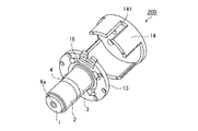
- a bottomed cylindrical mounting jig 14 is fixed to the base plate 13 so as to cover the bottom bridge 9.
- the bottom 141 of the mounting jig 14 is formed so as to be freely attachable to an external device such as a tip of a part assembly robot.
- a substantially cylindrical protective cover 15 is attached to the base plate 13 so as to cover the side peripheral portions of the center yoke 1 and the outer yoke 10.
- a gap is provided between the inner peripheral portion of the protective cover 15 and the center yoke 1, the outer yoke 10, the top bridge 8 and the bottom bridge 9.
- a plurality of heat radiating fins 151 are formed on the outer periphery of the protective cover 15.
- the mounting jig 14 and the protective cover 15 constitute a heat radiating member.
- the base plate 13 is provided with a ring-shaped magnetic plate 16.
- the magnetic body plate 16 is disposed to face the second magnet array 12.
- the magnetic plate 16 functions as a so-called “magnet clamp” for holding the second magnet array 12 in contact with the base plate 13 by the linear motion of the outer yoke 10 by magnetic force (attraction).
- the center yoke 1, the first coil 2, the second coil 3, the third coil 4, the bearing members 6 a and 6 b, the base plate 13, the mounting jig 14, the protective cover 15, and the magnetic body plate 16 constitute a fixed portion 200.
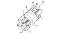
- the shaft 7, the top bridge 8, the bottom bridge 9, the outer yoke 10, the first magnet array 11, and the second magnet array 12 constitute a movable part 201.
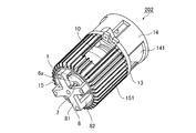
- the fixed portion 200 and the movable portion 201 constitute an actuator 202.
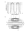
- FIG. 8A is a characteristic diagram showing the magnitude of the magnetic flux density by the first magnet array 11 and the second magnet array 12 with respect to the position coordinates in the axial direction of the movable portion 201.
- FIG. 8B shows the magnetic flux ⁇ formed by the first magnet array 11 and the second magnet array 12 in the cross section of the actuator 202 along the ABCD plane of FIG.
- the magnetic flux ⁇ formed by the first magnet array 11 and the second magnet array 12 is a loop-shaped magnetic flux passing through the entire circumference of the outer yoke 10 and the inside of the center yoke 1.
- a general voice coil motor is provided with a yoke (so-called “return yoke”) for folding the magnetic flux separately from the center yoke 1 and the outer yoke 10 in order to form a loop-shaped magnetic flux.
- the actuator 202 according to the first embodiment has a structure in which two motors are connected in series, the magnetic flux is folded back by the center yoke 1 and the outer yoke 10, so that a return yoke can be eliminated. With this structure, the actuator 202 can be reduced in size.
- the entire circumference of the outer yoke 10 can be used for a magnetic circuit, and the magnetic resistance is low. Become. For this reason, the thickness of the outer yoke 10 can be reduced, and the actuator 202 can be reduced in weight.
- the central portion of the center yoke 1 has a low magnetic flux density, the ratio contributing to the formation of the magnetic circuit is small. Therefore, even if the hollow bearing portion 5 is provided at the center of the center yoke 1, the efficiency of the actuator 202 does not decrease so much. For this reason, by adopting the middle bearing structure with the shaft 7, the top bridge 8 and the bottom bridge 9, it is smaller than the conventional linear motor which has adopted the outer bearing structure with the fixed base and the slider without reducing the efficiency. can do.
- a current source (not shown) supplies current to the first coil 2, the second coil 3, and the third coil 4, so that the movable portion 201 moves linearly with respect to the fixed portion 200.
- the first coil 2, the second coil 3, and the third coil 4 generate heat due to copper loss.
- the yoke material itself also generates heat due to iron loss. In applications where acceleration / deceleration is not repeated frequently with a linear motor, copper loss is dominant over iron loss, and the generated heat is transmitted to the center yoke 1.
- the center yoke 1 and the shaft 7 are thermally separated by the bearings of the bearing members 6a and 6b. That is, the fixed part 200 around which the first coil 2, the second coil 3, and the third coil 4 are wound and the movable part 201 provided with an end effector (not shown) are thermally separated. Thereby, it can prevent that the end effector etc. which were installed in the actuator movable part become high temperature.
- the heat capacity of the center yoke 1 is set to be sufficiently large with respect to the heat generation of the first coil 2, the second coil 3, and the third coil 4, the heat capacity that is a movable part as in Patent Document 1 is small. Compared with an actuator in which a coil is installed on a bobbin, the temperature of the center yoke 1 does not rise rapidly in a short time. In addition, since the coil of the heat generation source is directly installed in the movable part of the actuator of Patent Document 1, the heat radiation path is only natural air cooling via the end effector unless a forced air cooling mechanism using air is used.
- the heat transferred from the first coil 2, the second coil 3, and the third coil 4 to the center yoke 1 is radiated to the mounting jig 14 and the protective cover 15 having a lower thermal resistance via the base plate 13. Is done.
- the temperature rise upper limit value of the actuator 202 can be significantly suppressed, and the time for reaching the upper limit, that is, the thermal time constant can be lengthened.
- the outer yoke 10 is in contact with the base plate 13 by continuing to pass a current through the coil (that is, the movable portion 201 has moved to the end on the base plate 13 side).
- the heat generation of the coil is large, for example, when the end effector grips a heavy workpiece with the actuator facing downward.
- the actuator 202 of the first embodiment holds the state in which the outer yoke 10 is in contact with the base plate 13 by the magnetic force (attractive force) between the magnetic body plate 16 and the second magnet array 12.
- the electric current sent through the 1st coil 2, the 2nd coil 3, and the 3rd coil 4 can be reduced or made into zero power, and the heat generation of the 1st coil 2, the 2nd coil 3, and the 3rd coil 4 can be controlled.
- the maximum current may be applied for a short time. As a result, the second magnet array 12 is detached from the magnetic plate 16 in the shortest time.
- the attractive force between the second magnet array 12 and the magnetic material plate 16 is inversely proportional to the distance and is attenuated in an accelerated manner, so that the movement distance can be monitored by a position sensor (not shown) and the influence of the attractive force can be ignored.
- the control mode may be switched.
- the actuator 202 supports the rod-shaped center yoke 1 inserted through the cylindrical outer yoke 10 and the outer yoke 10 so as to be linearly movable along the axial direction of the center yoke 1.
- the first magnet array 11 and the second magnet array 12 provided so as to face each other, a plate-like base plate 13 provided at one end of the center yoke 1, and a heat radiating member in contact with the base plate 13. .
- bearing members 6a and 6b are interposed between the bearing portion 5 and the shaft 7. By thermally separating the bearing portion 5 and the shaft 7 by the bearings of the bearing members 6a and 6b, it is possible to prevent the end effector from reaching a high temperature.
- the actuator 202 uses a protective cover 15 that covers the side peripheral portions of the center yoke 1 and the outer yoke 10 as a heat radiating member.
- a plurality of radiating fins 151 are provided on the outer periphery of the protective cover 15.
- the base plate 13 has a magnetic plate 16 disposed to face the second magnet array 12. Since the magnetic plate 16 functions as a magnet clamp, the currents flowing through the first coil 2, the second coil 3, and the third coil 4 are reduced, and the first coil 2, the second coil 3, and the third coil 4 are reduced. Heat generation can be suppressed.
- the support member supports the outer yoke 10 so as to be rotatable with respect to the axis of the center yoke 1.
- the actuator 202 having a small size and two degrees of freedom can be obtained.
- FIG. 11 to 13 an actuator provided with holes for air cooling or refrigerant will be described. Components similar to those of the actuator 202 of the first embodiment shown in FIGS. 1 to 7 are denoted by the same reference numerals, and description thereof is omitted.
- the base plate 13 has a plurality of through holes 17 a and 17 b in the vicinity of the shaft 7.
- the center yoke 1 has a hole 18 communicating with the through holes 17a and 17b.
- the hole 18 connects the through holes 17a and 17b along the vicinity of the bearing portion 5 so that air or refrigerant flows. In this way, the actuator 203 is configured.
- the central portion of the center yoke 1 has a low magnetic flux density, and therefore does not contribute much to the formation of the magnetic circuit. Therefore, even if the hole 18 is provided along the vicinity of the axis of the center yoke 1, the operation efficiency of the actuator 202 is not greatly reduced.
- the heat generated by the first coil 2, the second coil 3, and the third coil 4 that cannot be cooled by the center yoke 1 is radiated to the mounting jig 14 and the protective cover 15 through the base plate 13. Thereby, the temperature rise of the actuator 202 can be suppressed, and the end effector can be prevented from becoming hot.
- the actuator 202 is provided with the hole 18 for air cooling or the refrigerant along the vicinity of the bearing portion 5 in the center yoke 1.
- the temperature rise can be further suppressed without lowering the operation efficiency of the actuator 202, and the end effector can be prevented from reaching a high temperature. .
- the actuator of the present invention can be used by being attached to a part assembly robot or the like.
Landscapes
- Engineering & Computer Science (AREA)
- Power Engineering (AREA)
- Physics & Mathematics (AREA)
- Chemical & Material Sciences (AREA)
- Combustion & Propulsion (AREA)
- Electromagnetism (AREA)
- Linear Motors (AREA)
- Motor Or Generator Cooling System (AREA)
- Reciprocating, Oscillating Or Vibrating Motors (AREA)
Abstract
アクチュエータ(202)は、筒状のアウターヨーク(10)に挿通された棒状のセンターヨーク(1)と、アウターヨーク(10)をセンターヨーク(1)の軸方向に沿って直動自在に支持する支持部材と、センターヨーク(1)に巻回された第1コイル(2)、第2コイル(3)及び第3コイル(4)と、アウターヨーク(10)の内周部に第1コイル(2)、第2コイル(3)及び第3コイル(4)と対向するように設けた第1マグネットアレイ(11)及び第2マグネットアレイ(12)と、センターヨーク(1)の一端部に設けた板状のベースプレート(13)と、ベースプレート(13)に当接した放熱部材とを有している。
Description
本発明は、アクチュエータに関するものであり、特に部品組み立て用のロボットなどに取り付けられるリニアアクチュエータに関する。
従来より、ロボットの先端部に、エンドエフェクタを取付けて部品組み立てなどの各種作業が行なわれているが、エンドエフェクタを駆動するアクチュエータとして固定部に対して可動部が直動自在なリニアアクチュエータが用いられる場合もある。
このリニアアクチュエータには、減速器を持たずに可動部を直接駆動する、いわゆる「ダイレクトドライブアクチュエータ」が用いられている。
ダイレクトドライブアクチュエータは、高速かつ高精度な動作制御が可能であり、ロボットと連動することにより作業範囲を拡大することができる反面、小型化や高出力化が難しい課題がある。また、ロボットの先端部に取り付けることができる重量は限られているため、小型かつ高出力で、発熱の少ないアクチュエータが求められている。
このリニアアクチュエータには、減速器を持たずに可動部を直接駆動する、いわゆる「ダイレクトドライブアクチュエータ」が用いられている。
ダイレクトドライブアクチュエータは、高速かつ高精度な動作制御が可能であり、ロボットと連動することにより作業範囲を拡大することができる反面、小型化や高出力化が難しい課題がある。また、ロボットの先端部に取り付けることができる重量は限られているため、小型かつ高出力で、発熱の少ないアクチュエータが求められている。
ダイレクトドライブアクチュエータの1つに、ネオジム磁石などの永久磁石が作る強力な磁界の中をコイルのみが往復運動するボイスコイルモータ(Voice Coil Motor,VCM)がある。ボイスコイルモータは、可動部を軽量に設計できる反面、ダイレクトドライブモータであるため体積当たりの出力が低く発熱しやすい課題がある。また、可動部に取り付けたハンドなどのエンドエフェクタに熱が直接伝わり、エンドエフェクタが高温になる課題がある。
これに対し、特許文献1のボイスコイルモータは、固定子にエアー注入機構を配置している。電機子コイルをエアー冷却することで、モータ体格を変更せずに特性を向上させている。
また、特許文献2のリニアモータは、複数のボイスコイル型リニアモータユニットを並設している。この構造により、体積増加を抑えつつ高出力化を図るとともに、可動部と固定部を熱的に分離している。
特許文献1のボイスコイルモータは、電機子コイルを冷却する構造を有しているものの、発生した熱を放熱する構造については開示されていない。
また可動部に設置された電機子コイルを直接エアーで冷却しているため、可動部の推力に影響を及ぼす。
また可動部に設置された電機子コイルを直接エアーで冷却しているため、可動部の推力に影響を及ぼす。
また、特許文献2のリニアモータは、2本の内ヨークを並設して、互いに隣接する外ヨークを用いて主磁路を形成しているため、1本の内ヨークを用いたリニアモータに対して幅が2倍になる。さらに、2本の内ヨークを有底箱状の固定台に収容し、固定台の開口部に設けたスライダによって外ヨークを直動自在に支持する構造(いわゆる「外軸受構造」)を採用している。この構造では、リニアモータを十分に小型化することができない課題があった。
本発明は、上記のような課題を解決するためになされたものであり、小型かつ高効率で、温度上昇を抑えたアクチュエータを提供することを目的とする。
本発明のアクチュエータは、筒状の外ヨークに挿通された棒状の内ヨークと、外ヨークを内ヨークの軸方向に沿って直動自在に支持する支持部材と、内ヨークに巻回されたコイルと、外ヨークの内周部にコイルと対向するように設けた磁石と、内ヨークの端部に設けた板状のベースプレートと、ベースプレートに当接した放熱部材と、を具備するものである。
本発明によれば、小型かつ高効率で、温度上昇を抑えたアクチュエータを得ることができる。
以下、この発明をより詳細に説明するために、この発明を実施するための形態について、添付の図面に従って説明する。
実施の形態1.
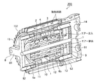
図1~図7を参照して、本発明の実施の形態1のアクチュエータについて説明する。
図中、1はセンターヨーク(内ヨーク)である。センターヨーク1は、略棒状の磁性体により構成されている。
実施の形態1.
図1~図7を参照して、本発明の実施の形態1のアクチュエータについて説明する。
図中、1はセンターヨーク(内ヨーク)である。センターヨーク1は、略棒状の磁性体により構成されている。
センターヨーク1には、互いの間に間隙を設けて第1コイル2及び第2コイル3が巻回されている。第1コイル2及び第2コイル3は、図示しない電流源に対して直列又は並列に接続されており、互いに逆向きの電流が流れるようになっている。
第1コイル2と第2コイル3間の間隙には、第3コイル4が巻回されている。第3コイル4は、図示しない切替制御部を介して電流源に接続されており、第1コイル2及び第2コイル3とは独立して、流れる電流の向きを切替自在になっている。
センターヨーク1の軸心に沿って、中空の軸受部5が形成されている。軸受部5の両端部には、軸受部材6a,6bがそれぞれ挿通されている。軸受部材6a,6bの中空部には、センターヨーク1よりも細長いシャフト7が挿通されている。シャフト7は、センターヨーク1に対して軸方向に直動自在に、かつ軸を中心に回動自在もしくは回動しない様に支持されている。
ここで、軸受部材6a,6bは、回動自在とする場合はボールブッシュなどで構成し、回動しない様にするためにはスプラインナットなどで構成する。センターヨーク1とシャフト7間は、軸受部材6a,6bが有するベアリングによって熱的に分離されている。
シャフト7の一端部には、トップブリッジ(第1ブリッジ部)8が嵌合され、かつ固定されている。シャフト7の他端部には、ボトムブリッジ(第2ブリッジ部)9が嵌合され、かつ固定されている。トップブリッジ8及びボトムブリッジ9は、略十字状の本体部81,91の先端部から、互いの対向方向に延伸された4本の腕部82,92を有している。シャフト7、トップブリッジ8及びボトムブリッジ9によって、いわゆる「中軸受構造」の支持部材が構成されている。
トップブリッジ8の腕部82の先端部とボトムブリッジ9の腕部92の先端部との間に、アウターヨーク(外ヨーク)10が固定されている。すなわち、アウターヨーク10は、センターヨーク1に対して直動自在、かつ回動自在もしくは回動しない様に支持されている。アウターヨーク10は、略筒状の磁性体により構成されている。
なお、本体部81,91の形状は十字状に限定されるものではなく、腕部82,92の本数は4本に限定されるものではない。トップブリッジ8及びボトムブリッジ9は、アウターヨーク10を少なくとも直動自在に支持するものであれば、任意の形状のものを用いて良い。
アウターヨーク10の一端部の内周部には、全周に亘って第1マグネットアレイ(磁石)11が設けられている。第1マグネットアレイ11は、複数個の永久磁石により構成されている。第1マグネットアレイ11は、間隙を設けて第1コイル2と対向している。また、第1マグネットアレイ11は、アウターヨーク10の直動位置に応じて第3コイル4とも対向するようになっている。
アウターヨーク10の他端部の内周部には、全周に亘って第2マグネットアレイ(磁石)12が設けられている。第2マグネットアレイ12は、複数個の永久磁石により構成されている。第2マグネットアレイ12は、間隙を設けて第2コイル3と対向している。また、第2マグネットアレイ12は、アウターヨーク10の直動位置に応じて第3コイル4とも対向するようになっている。
ここで、第1マグネットアレイ11と第2マグネットアレイ12とは、互いに逆向きの磁極を有している。例えば、第1マグネットアレイ11は、アウターヨーク10との当接面側にN極があり、第1コイル2及び第3コイル4との対向面側にS極がある。一方、第2マグネットアレイ12は、アウターヨーク10との当接面側にS極があり、第2コイル3及び第3コイル4との対向面側にN極がある。
センターヨーク1の一端部には、鍔状のベースプレート13が固定されている。ベースプレート13には4つの貫通孔131が設けられており、ボトムブリッジ9の腕部92のそれぞれが摺動自在に挿通している。
ベースプレート13には、ボトムブリッジ9を覆うように、有底筒状の取付冶具14が固定されている。取付冶具14の底部141は、部品組み立て用のロボットの先端部などの外部装置に対して取付自在に形成されている。
ベースプレート13には、センターヨーク1及びアウターヨーク10の側周部を覆うように、略円筒状の保護カバー15が取り付けられている。保護カバー15の内周部と、センターヨーク1、アウターヨーク10、トップブリッジ8及びボトムブリッジ9との間には間隙が設けられている。保護カバー15の外周部には、複数の放熱フィン151が形成されている。取付冶具14及び保護カバー15によって、放熱部材が構成されている。
ベースプレート13には、リング状の磁性体板16が設けられている。磁性体板16は、第2マグネットアレイ12と対向配置されている。磁性体板16は、アウターヨーク10の直動によりベースプレート13に当接した第2マグネットアレイ12を磁力(引力)によって保持する、いわゆる「マグネットクランプ」の機能を果たすものである。
センターヨーク1、第1コイル2、第2コイル3、第3コイル4、軸受部材6a,6b、ベースプレート13、取付冶具14、保護カバー15及び磁性体板16によって、固定部200が構成されている。シャフト7、トップブリッジ8、ボトムブリッジ9、アウターヨーク10、第1マグネットアレイ11及び第2マグネットアレイ12によって、可動部201が構成されている。固定部200及び可動部201によって、アクチュエータ202が構成されている。
次に、図8を参照して、アクチュエータ202の磁束密度の分布について説明する。
図8(a)は、可動部201の軸方向の位置座標に対する、第1マグネットアレイ11及び第2マグネットアレイ12による磁束密度の大きさを示す特性図である。図8(b)は、図2のA-B-C-D面に沿うアクチュエータ202の断面において、第1マグネットアレイ11及び第2マグネットアレイ12が形成する磁束φを示している。
図8(a)は、可動部201の軸方向の位置座標に対する、第1マグネットアレイ11及び第2マグネットアレイ12による磁束密度の大きさを示す特性図である。図8(b)は、図2のA-B-C-D面に沿うアクチュエータ202の断面において、第1マグネットアレイ11及び第2マグネットアレイ12が形成する磁束φを示している。
図8(b)に示す如く、第1マグネットアレイ11及び第2マグネットアレイ12が形成する磁束φは、アウターヨーク10の全周と、センターヨーク1の内部とを通るループ状の磁束となる。
一般的なボイスコイルモータは、ループ状の磁束を形成するために、磁束を折返すためのヨーク(いわゆる「リターンヨーク」)をセンターヨーク1及びアウターヨーク10とは別に設けている。実施の形態1のアクチュエータ202は、2つのモータを直列に接続した構造でありながら、センターヨーク1及びアウターヨーク10で磁束を折返しているためリターンヨークを不要とすることができる。この構造により、アクチュエータ202を小型にすることができる。
また、アウターヨーク10の両端部の全周に亘って第1マグネットアレイ11及び第2マグネットアレイ12を設けることで、アウターヨーク10の全周を磁気回路に使用できるようになり、磁気抵抗が低くなる。このため、アウターヨーク10の肉厚を薄くすることができ、アクチュエータ202を軽量にすることができる。
さらに、センターヨーク1の中心部は磁束密度が低いため、磁気回路の形成に寄与する割合が少ない。したがって、センターヨーク1の軸心に中空の軸受部5を設けても、アクチュエータ202の効率があまり低下しない。このため、シャフト7、トップブリッジ8及びボトムブリッジ9による中軸受構造を採用することで、固定台及びスライダによる外軸受構造を採用していた従来のリニアモータよりも、効率を落とすことなく小型にすることができる。
次に、図9を参照して、アクチュエータ202の放熱動作について説明する。
図示しない電流源が、第1コイル2、第2コイル3及び第3コイル4に電流を供給することで、固定部200に対して可動部201が直動する。流れた電流に応じて、銅損により第1コイル2、第2コイル3及び第3コイル4が発熱する。
また交番磁界が発生するように第1コイル2、第2コイル3及び第3コイル4に電流を流すと鉄損でヨーク材自体も発熱する。
尚、リニアモータで加減速を頻繁に繰り返さない用途では鉄損に対し銅損が支配的であり、発生した熱は、センターヨーク1に伝わる。
図示しない電流源が、第1コイル2、第2コイル3及び第3コイル4に電流を供給することで、固定部200に対して可動部201が直動する。流れた電流に応じて、銅損により第1コイル2、第2コイル3及び第3コイル4が発熱する。
また交番磁界が発生するように第1コイル2、第2コイル3及び第3コイル4に電流を流すと鉄損でヨーク材自体も発熱する。
尚、リニアモータで加減速を頻繁に繰り返さない用途では鉄損に対し銅損が支配的であり、発生した熱は、センターヨーク1に伝わる。
このとき、センターヨーク1とシャフト7間は、軸受部材6a,6bのベアリングによって熱的に分離されている。すなわち、第1コイル2、第2コイル3及び第3コイル4を巻回した固定部200と、図示しないエンドエフェクタを設けた可動部201とが熱的に分離されている。これにより、アクチュエータ可動部に設置されたエンドエフェクタなどが高温になるのを防ぐことができる。
また、センターヨーク1の熱容量は、第1コイル2、第2コイル3及び第3コイル4の発熱に対して十分に大きく設定されているため、特許文献1のように可動部である熱容量の小さいボビンにコイルを設置するアクチュエータと比較して、センターヨーク1の温度が短時間に急激に上昇することはない。
また特許文献1のアクチュエータは可動部に発熱源であるコイルが直接設置されているため、エアーによる強制空冷機構を使用しない限り放熱経路もエンドエフェクタを介しての自然空冷しかない。
一方、本願のアクチュエータにおいては第1コイル2、第2コイル3及び第3コイル4からセンターヨーク1に伝わった熱は、ベースプレート13を介してさらに熱抵抗の低い取付冶具14及び保護カバー15に放熱される。これにより、大幅にアクチュエータ202の温度上昇上限値を抑制し、上限に達する時間、つまり熱時定数を長くすることができる。
また特許文献1のアクチュエータは可動部に発熱源であるコイルが直接設置されているため、エアーによる強制空冷機構を使用しない限り放熱経路もエンドエフェクタを介しての自然空冷しかない。
一方、本願のアクチュエータにおいては第1コイル2、第2コイル3及び第3コイル4からセンターヨーク1に伝わった熱は、ベースプレート13を介してさらに熱抵抗の低い取付冶具14及び保護カバー15に放熱される。これにより、大幅にアクチュエータ202の温度上昇上限値を抑制し、上限に達する時間、つまり熱時定数を長くすることができる。
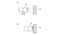
次に、図10を参照して、磁性体板16によるマグネットクランプ動作について説明する。
図10に示す如く、可動部201の直動により第2マグネットアレイ12がベースプレート13に対向配置されたリング状の磁性体板16に近づくと、第2マグネットアレイ12の側部から漏れた磁束によって、第2マグネットアレイ12が磁性体板16に引き寄せられる。第2マグネットアレイ12が磁性体板16に当接すると、磁性体板16は磁力によって第2マグネットアレイ12が当接した状態を保持する。
図10に示す如く、可動部201の直動により第2マグネットアレイ12がベースプレート13に対向配置されたリング状の磁性体板16に近づくと、第2マグネットアレイ12の側部から漏れた磁束によって、第2マグネットアレイ12が磁性体板16に引き寄せられる。第2マグネットアレイ12が磁性体板16に当接すると、磁性体板16は磁力によって第2マグネットアレイ12が当接した状態を保持する。
磁性体板16を有しない従来のアクチュエータは、コイルに電流を流し続けることで、アウターヨーク10がベースプレート13に当接した状態(すなわち、可動部201がベースプレート13側の端部まで移動した状態)を保持していた。このため、アクチュエータが下向きの状態においてエンドエフェクタで重量の大きいワークを把持する場合などコイルの発熱が大きくなっていた。
これに対し、実施の形態1のアクチュエータ202は、磁性体板16と第2マグネットアレイ12間の磁力(引力)によって、アウターヨーク10がベースプレート13に当接した状態を保持している。これにより、第1コイル2、第2コイル3及び第3コイル4に流す電流を低減もしくはゼロパワー化でき、第1コイル2、第2コイル3及び第3コイル4の発熱を抑制することができる。
尚、磁力によって第2マグネットアレイ12が磁性体板16に当接して保持されている状態を解除するためには最大電流を短い時間加えてやれば良い。
このことにより第2マグネットアレイ12は最短時間で磁性体板16から離脱する。
このとき第2マグネットアレイ12と磁性体板16の吸引力はその距離に応じて反比例し加速度的に減衰するので、図示していない位置センサにより移動距離を監視し吸引力の影響が無視できる位置(1mm程度)まで離れたら制御モードに切り換えれば良い。
尚、磁力によって第2マグネットアレイ12が磁性体板16に当接して保持されている状態を解除するためには最大電流を短い時間加えてやれば良い。
このことにより第2マグネットアレイ12は最短時間で磁性体板16から離脱する。
このとき第2マグネットアレイ12と磁性体板16の吸引力はその距離に応じて反比例し加速度的に減衰するので、図示していない位置センサにより移動距離を監視し吸引力の影響が無視できる位置(1mm程度)まで離れたら制御モードに切り換えれば良い。
以上のように、実施の形態1のアクチュエータ202は、筒状のアウターヨーク10に挿通された棒状のセンターヨーク1と、アウターヨーク10をセンターヨーク1の軸方向に沿って直動自在に支持する支持部材と、センターヨーク1に巻回された第1コイル2、第2コイル3及び第3コイル4と、アウターヨーク10の内周部に第1コイル2、第2コイル3及び第3コイル4と対向するように設けた第1マグネットアレイ11及び第2マグネットアレイ12と、センターヨーク1の一端部に設けた板状のベースプレート13と、ベースプレート13に当接した放熱部材とを有している。これにより、中軸受構造を採用することで、小型かつ高効率なアクチュエータ202を実現しつつ、アクチュエータ202の温度上昇を抑制することができる。
また、アクチュエータ202は、軸受部5とシャフト7間に軸受部材6a,6bを介在させている。軸受部材6a,6bのベアリングにより軸受部5とシャフト7間を熱的に分離することで、エンドエフェクタが高温になるのを防ぐことができる。
また、アクチュエータ202は、放熱部材にセンターヨーク1及びアウターヨーク10の側周部を覆う保護カバー15を用いている。保護カバー15の外周部に、複数の放熱フィン151を設けている。これにより、センターヨーク1からベースプレート13に放熱された熱が、取付冶具14を介してロボットなどの外部装置に伝わるのを低減することができる。
また、ベースプレート13は、第2マグネットアレイ12と対向配置された磁性体板16を有している。磁性体板16がマグネットクランプの機能を果たすことで、第1コイル2、第2コイル3及び第3コイル4に流す電流を低減して、第1コイル2、第2コイル3及び第3コイル4の発熱を抑制することができる。
また、支持部材は、アウターヨーク10をセンターヨーク1の軸心に対して回動自在に支持している。これにより、小型かつ2自由度のアクチュエータ202を得ることができる。
実施の形態2.
図11~図13を参照して、空冷用又は冷媒用の穴部を設けたアクチュエータについて説明する。なお、図1~図7に示す実施の形態1のアクチュエータ202と同様の構成部材には同一符号を付して説明を省略する。
図11~図13を参照して、空冷用又は冷媒用の穴部を設けたアクチュエータについて説明する。なお、図1~図7に示す実施の形態1のアクチュエータ202と同様の構成部材には同一符号を付して説明を省略する。
ベースプレート13は、シャフト7の近傍に複数の貫通孔17a,17bを有している。センターヨーク1は、貫通孔17a,17bと連通する穴部18を有している。穴部18は、軸受部5の近傍に沿うように貫通孔17a,17b間を繋いでおり、空気又は冷媒が流れるようになっている。このようにして、アクチュエータ203が構成されている。
次に、図13を参照して、アクチュエータ203の冷却動作について説明する。
まず、ベースプレート13の貫通孔17aに空気又は冷媒を注入する。空気又は冷媒は、センターヨーク1の穴部18を通過して、貫通孔17bから排出される。これにより、センターヨーク1を強制的に冷却する。
まず、ベースプレート13の貫通孔17aに空気又は冷媒を注入する。空気又は冷媒は、センターヨーク1の穴部18を通過して、貫通孔17bから排出される。これにより、センターヨーク1を強制的に冷却する。
ここで、実施の形態1で説明したように、センターヨーク1の中心部は磁束密度が低いため、磁気回路の形成にあまり寄与しない。したがって、センターヨーク1の軸心の近傍に沿って穴部18を設けても、アクチュエータ202の動作効率が大きく低下することはない。
また、センターヨーク1で冷却しきれなかった第1コイル2、第2コイル3及び第3コイル4の発熱は、ベースプレート13を介して取付冶具14及び保護カバー15に放熱される。これにより、アクチュエータ202の温度上昇を抑制するとともに、エンドエフェクタが高温なるのを防ぐことができる。
以上のように、実施の形態2のアクチュエータ202は、センターヨーク1に、軸受部5の近傍に沿うように空冷用又は冷媒用の穴部18を設けている。ベースプレート13の貫通孔17a,17bから空気又は冷媒を注入及び排出することで、アクチュエータ202の動作効率を低下させずに温度上昇をさらに抑制して、エンドエフェクタが高温になるのを防ぐことができる。
なお、本願発明はその発明の範囲内において、各実施の形態の自由な組み合わせ、あるいは各実施の形態の任意の構成要素の変形、もしくは各実施の形態において任意の構成要素の省略が可能である。
本発明のアクチュエータは、部品組み立て用のロボットなどに取り付けて用いることができる。
1 センターヨーク(内ヨーク)
2 第1コイル
3 第2コイル
4 第3コイル
5 軸受部
6a,6b 軸受部材
7 シャフト
8 トップブリッジ(第1ブリッジ部)
9 ボトムブリッジ(第2ブリッジ部)
10 アウターヨーク(外ヨーク)
11 第1マグネットアレイ(磁石)
12 第2マグネットアレイ(磁石)
13 ベースプレート
14 取付冶具
15 保護カバー
16 磁性体板
17a,17b 貫通孔
18 穴部
81 本体部
82 腕部
91 本体部
92 腕部
131 貫通孔
141 底部
151 放熱フィン
200 固定部
201 可動部
202,203 アクチュエータ
2 第1コイル
3 第2コイル
4 第3コイル
5 軸受部
6a,6b 軸受部材
7 シャフト
8 トップブリッジ(第1ブリッジ部)
9 ボトムブリッジ(第2ブリッジ部)
10 アウターヨーク(外ヨーク)
11 第1マグネットアレイ(磁石)
12 第2マグネットアレイ(磁石)
13 ベースプレート
14 取付冶具
15 保護カバー
16 磁性体板
17a,17b 貫通孔
18 穴部
81 本体部
82 腕部
91 本体部
92 腕部
131 貫通孔
141 底部
151 放熱フィン
200 固定部
201 可動部
202,203 アクチュエータ
Claims (11)
- 筒状の外ヨークに挿通された棒状の内ヨークと、
前記外ヨークを前記内ヨークの軸方向に沿って直動自在に支持する支持部材と、
前記内ヨークに巻回されたコイルと、
前記外ヨークの内周部に前記コイルと対向するように設けた磁石と、
前記内ヨークの一端部に設けた板状のベースプレートと、
前記ベースプレートに当接した放熱部材と、
を具備することを特徴とするアクチュエータ。 - 前記内ヨークの軸心に沿う中空の軸受部を具備し、
前記支持部材は、
前記軸受部に挿通され、前記内ヨークに対して直動自在に支持されたシャフトと、
前記シャフトの一端部に嵌合され、かつ前記外ヨークの一端部に当接した第1ブリッジ部と、
前記シャフトの他端部に嵌合され、かつ前記外ヨークの他端部に当接した第2ブリッジ部と、
を具備することを特徴とする請求項1記載のアクチュエータ。 - 前記軸受部と前記シャフト間にベアリングを介在させたことを特徴とする請求項2記載のアクチュエータ。
- 前記放熱部材は、前記内ヨーク及び前記外ヨークの側周部を覆う保護カバーであることを特徴とする請求項1記載のアクチュエータ。
- 前記保護カバーは円筒状であり、
前記保護カバーの内周部と前記内ヨーク及び前記外ヨークとの間に間隙を設け、
前記保護カバーの外周部に複数の放熱フィンを設けた
ことを特徴とする請求項4記載のアクチュエータ。 - 前記放熱部材は、前記ベースプレートから前記内ヨークと逆向きに延伸され、かつ外部装置に取付自在な取付冶具であることを特徴とする請求項1記載のアクチュエータ。
- 前記取付冶具は、部品組み立て用のロボットに取付自在に形成されていることを特徴とする請求項6記載のアクチュエータ。
- 前記ベースプレートは、前記磁石と対向配置された磁性体板を具備することを特徴とする請求項1記載のアクチュエータ。
- 前記磁石は前記外ヨークの内周部の全周に亘って設けられており、
前記磁性体板はリング状である
ことを特徴とする請求項8記載のアクチュエータ。 - 前記内ヨークは、前記軸受部の近傍に沿うように空冷用又は冷媒用の穴部を具備することを特徴とする請求項2記載のアクチュエータ。
- 前記支持部材は、前記外ヨークを前記内ヨークの軸心に対して回動自在に支持することを特徴とする請求項1記載のアクチュエータ。
Priority Applications (2)
| Application Number | Priority Date | Filing Date | Title |
|---|---|---|---|
| CN201580058218.5A CN107112861B (zh) | 2014-10-28 | 2015-10-09 | 致动器 |
| US15/522,663 US10594199B2 (en) | 2014-10-28 | 2015-10-09 | Actuator having heat radiation member |
Applications Claiming Priority (2)
| Application Number | Priority Date | Filing Date | Title |
|---|---|---|---|
| JP2014219525A JP6335754B2 (ja) | 2014-10-28 | 2014-10-28 | アクチュエータ |
| JP2014-219525 | 2014-10-28 |
Publications (1)
| Publication Number | Publication Date |
|---|---|
| WO2016067902A1 true WO2016067902A1 (ja) | 2016-05-06 |
Family
ID=55857243
Family Applications (1)
| Application Number | Title | Priority Date | Filing Date |
|---|---|---|---|
| PCT/JP2015/078782 Ceased WO2016067902A1 (ja) | 2014-10-28 | 2015-10-09 | アクチュエータ |
Country Status (4)
| Country | Link |
|---|---|
| US (1) | US10594199B2 (ja) |
| JP (1) | JP6335754B2 (ja) |
| CN (1) | CN107112861B (ja) |
| WO (1) | WO2016067902A1 (ja) |
Citations (2)
| Publication number | Priority date | Publication date | Assignee | Title |
|---|---|---|---|---|
| JP2009136118A (ja) * | 2007-11-30 | 2009-06-18 | Hitachi Ltd | 同期形リニアモータ |
| JP2009290991A (ja) * | 2008-05-29 | 2009-12-10 | Iai:Kk | ボイスコイルモータとアクチュエータ |
Family Cites Families (15)
| Publication number | Priority date | Publication date | Assignee | Title |
|---|---|---|---|---|
| EP1020013B1 (en) * | 1997-10-04 | 2004-04-28 | Z & D Limited | Linear motor compressor |
| JP2000023442A (ja) * | 1998-07-03 | 2000-01-21 | Foster Electric Co Ltd | リニアアクチュエータ |
| JP3683199B2 (ja) | 2001-03-16 | 2005-08-17 | 松下電器産業株式会社 | リニアモータ |
| JP2004328889A (ja) | 2003-04-24 | 2004-11-18 | Yaskawa Electric Corp | ボイスコイルモータ |
| US7242118B2 (en) * | 2003-07-31 | 2007-07-10 | Japan Servo Co., Ltd. | Toroidal-coil linear stepping motor, toroidal-coil linear reciprocating motor, cylinder compressor and cylinder pump using these motors |
| US7032400B2 (en) * | 2004-03-29 | 2006-04-25 | Hussmann Corporation | Refrigeration unit having a linear compressor |
| US8615976B1 (en) * | 2010-06-21 | 2013-12-31 | Hydro-Gear Limited Partnership | Electric motor clutch/brake assembly |
| US20130169071A1 (en) * | 2010-06-30 | 2013-07-04 | Nidec Copal Corporation | Oscillating actuator |
| JP5603724B2 (ja) * | 2010-09-21 | 2014-10-08 | カヤバ工業株式会社 | リニアアクチュエータ |
| CN102013783B (zh) * | 2010-12-23 | 2012-07-25 | 天津职业技术师范大学 | 一种轻型直流直线电机 |
| WO2013137578A1 (ko) * | 2012-03-16 | 2013-09-19 | 크레신 주식회사 | 선형 진동자 |
| CN103560639A (zh) * | 2013-11-20 | 2014-02-05 | 东南大学 | 一种高功率因数直线往复振荡电机 |
| CN104253520B (zh) * | 2014-09-23 | 2017-01-25 | 中国北方车辆研究所 | 一种鼠笼式圆筒型直线电机 |
| JP6289396B2 (ja) * | 2014-10-28 | 2018-03-07 | アズビル株式会社 | アクチュエータ |
| CN109983677A (zh) * | 2016-11-16 | 2019-07-05 | 松下知识产权经营株式会社 | 致动器和照相机装置 |
-
2014
- 2014-10-28 JP JP2014219525A patent/JP6335754B2/ja active Active
-
2015
- 2015-10-09 US US15/522,663 patent/US10594199B2/en active Active
- 2015-10-09 CN CN201580058218.5A patent/CN107112861B/zh active Active
- 2015-10-09 WO PCT/JP2015/078782 patent/WO2016067902A1/ja not_active Ceased
Patent Citations (2)
| Publication number | Priority date | Publication date | Assignee | Title |
|---|---|---|---|---|
| JP2009136118A (ja) * | 2007-11-30 | 2009-06-18 | Hitachi Ltd | 同期形リニアモータ |
| JP2009290991A (ja) * | 2008-05-29 | 2009-12-10 | Iai:Kk | ボイスコイルモータとアクチュエータ |
Also Published As
| Publication number | Publication date |
|---|---|
| JP2016086596A (ja) | 2016-05-19 |
| CN107112861B (zh) | 2019-03-22 |
| US20170338727A1 (en) | 2017-11-23 |
| CN107112861A (zh) | 2017-08-29 |
| JP6335754B2 (ja) | 2018-05-30 |
| US10594199B2 (en) | 2020-03-17 |
Similar Documents
| Publication | Publication Date | Title |
|---|---|---|
| US7732951B2 (en) | Moving-magnet type linear motor | |
| JP6301463B2 (ja) | 機械式共鳴システム及び空冷ボイスコイル式アクチュエータ | |
| EP2621067B1 (en) | Linear actuator | |
| JP2016537963A (ja) | 平型ボイスコイルモータ | |
| JP5646476B2 (ja) | アクチュエータ | |
| JP2010158140A (ja) | リニアモータ | |
| JP6289396B2 (ja) | アクチュエータ | |
| KR0183618B1 (ko) | 보이스 코일 모터 | |
| JP6335754B2 (ja) | アクチュエータ | |
| JP5072064B2 (ja) | 円筒型リニアモータ | |
| JP5447308B2 (ja) | リニアモータ | |
| JP2009136118A (ja) | 同期形リニアモータ | |
| JP2005328592A (ja) | 球面モータ | |
| JP2002218727A (ja) | 磁石式アクチュエータ | |
| JP5375039B2 (ja) | 直動発電機 | |
| JP2008206356A (ja) | 可動磁石型リニアアクチュエータ | |
| JP2010063313A (ja) | リニアモータ | |
| JP7115185B2 (ja) | 可動コイル型ボイスコイルモータ | |
| JPH1169754A (ja) | 永久磁石可動形リニア直流モータ | |
| US12149142B1 (en) | Linear electromagnetic actuator with improved coil cooling | |
| JP5696403B2 (ja) | リニアアクチュエータ | |
| US20170179807A1 (en) | Magnetic motor device of an electrodynamic transducer | |
| CN111146920B (zh) | 一种音圈电机 | |
| KR20260028704A (ko) | 릴럭턴스 액추에이터 | |
| WO2016067903A1 (ja) | アクチュエータ |
Legal Events
| Date | Code | Title | Description |
|---|---|---|---|
| 121 | Ep: the epo has been informed by wipo that ep was designated in this application |
Ref document number: 15854062 Country of ref document: EP Kind code of ref document: A1 |
|
| NENP | Non-entry into the national phase |
Ref country code: DE |
|
| 122 | Ep: pct application non-entry in european phase |
Ref document number: 15854062 Country of ref document: EP Kind code of ref document: A1 |