WO2016067563A1 - 基板洗浄ロール、基板洗浄装置、及び基板洗浄方法 - Google Patents
基板洗浄ロール、基板洗浄装置、及び基板洗浄方法 Download PDFInfo
- Publication number
- WO2016067563A1 WO2016067563A1 PCT/JP2015/005280 JP2015005280W WO2016067563A1 WO 2016067563 A1 WO2016067563 A1 WO 2016067563A1 JP 2015005280 W JP2015005280 W JP 2015005280W WO 2016067563 A1 WO2016067563 A1 WO 2016067563A1
- Authority
- WO
- WIPO (PCT)
- Prior art keywords
- substrate
- substrate cleaning
- cleaning
- cleaning roll
- bevel
- Prior art date
- Legal status (The legal status is an assumption and is not a legal conclusion. Google has not performed a legal analysis and makes no representation as to the accuracy of the status listed.)
- Ceased
Links
Images



Classifications
-
- H—ELECTRICITY
- H10—SEMICONDUCTOR DEVICES; ELECTRIC SOLID-STATE DEVICES NOT OTHERWISE PROVIDED FOR
- H10P—GENERIC PROCESSES OR APPARATUS FOR THE MANUFACTURE OR TREATMENT OF DEVICES COVERED BY CLASS H10
- H10P72/00—Handling or holding of wafers, substrates or devices during manufacture or treatment thereof
- H10P72/04—Apparatus for manufacture or treatment
- H10P72/0402—Apparatus for fluid treatment
- H10P72/0406—Apparatus for fluid treatment for cleaning followed by drying, rinsing, stripping, blasting or the like
- H10P72/0411—Apparatus for fluid treatment for cleaning followed by drying, rinsing, stripping, blasting or the like for wet cleaning or washing
- H10P72/0412—Apparatus for fluid treatment for cleaning followed by drying, rinsing, stripping, blasting or the like for wet cleaning or washing using mainly scrubbing means, e.g. brushes
-
- B—PERFORMING OPERATIONS; TRANSPORTING
- B08—CLEANING
- B08B—CLEANING IN GENERAL; PREVENTION OF FOULING IN GENERAL
- B08B1/00—Cleaning by methods involving the use of tools
- B08B1/10—Cleaning by methods involving the use of tools characterised by the type of cleaning tool
- B08B1/14—Wipes; Absorbent members, e.g. swabs or sponges
-
- B—PERFORMING OPERATIONS; TRANSPORTING
- B08—CLEANING
- B08B—CLEANING IN GENERAL; PREVENTION OF FOULING IN GENERAL
- B08B1/00—Cleaning by methods involving the use of tools
- B08B1/30—Cleaning by methods involving the use of tools by movement of cleaning members over a surface
- B08B1/32—Cleaning by methods involving the use of tools by movement of cleaning members over a surface using rotary cleaning members
- B08B1/34—Cleaning by methods involving the use of tools by movement of cleaning members over a surface using rotary cleaning members rotating about an axis parallel to the surface
-
- B—PERFORMING OPERATIONS; TRANSPORTING
- B08—CLEANING
- B08B—CLEANING IN GENERAL; PREVENTION OF FOULING IN GENERAL
- B08B3/00—Cleaning by methods involving the use or presence of liquid or steam
- B08B3/04—Cleaning involving contact with liquid
- B08B3/08—Cleaning involving contact with liquid the liquid having chemical or dissolving effect
-
- H—ELECTRICITY
- H10—SEMICONDUCTOR DEVICES; ELECTRIC SOLID-STATE DEVICES NOT OTHERWISE PROVIDED FOR
- H10P—GENERIC PROCESSES OR APPARATUS FOR THE MANUFACTURE OR TREATMENT OF DEVICES COVERED BY CLASS H10
- H10P52/00—Grinding, lapping or polishing of wafers, substrates or parts of devices
-
- H—ELECTRICITY
- H10—SEMICONDUCTOR DEVICES; ELECTRIC SOLID-STATE DEVICES NOT OTHERWISE PROVIDED FOR
- H10P—GENERIC PROCESSES OR APPARATUS FOR THE MANUFACTURE OR TREATMENT OF DEVICES COVERED BY CLASS H10
- H10P70/00—Cleaning of wafers, substrates or parts of devices
- H10P70/20—Cleaning during device manufacture
-
- H—ELECTRICITY
- H10—SEMICONDUCTOR DEVICES; ELECTRIC SOLID-STATE DEVICES NOT OTHERWISE PROVIDED FOR
- H10P—GENERIC PROCESSES OR APPARATUS FOR THE MANUFACTURE OR TREATMENT OF DEVICES COVERED BY CLASS H10
- H10P70/00—Cleaning of wafers, substrates or parts of devices
- H10P70/50—Cleaning of wafers, substrates or parts of devices characterised by the part to be cleaned
- H10P70/54—Cleaning of wafer edges
-
- H—ELECTRICITY
- H10—SEMICONDUCTOR DEVICES; ELECTRIC SOLID-STATE DEVICES NOT OTHERWISE PROVIDED FOR
- H10P—GENERIC PROCESSES OR APPARATUS FOR THE MANUFACTURE OR TREATMENT OF DEVICES COVERED BY CLASS H10
- H10P70/00—Cleaning of wafers, substrates or parts of devices
- H10P70/60—Cleaning only by mechanical processes
-
- H—ELECTRICITY
- H10—SEMICONDUCTOR DEVICES; ELECTRIC SOLID-STATE DEVICES NOT OTHERWISE PROVIDED FOR
- H10P—GENERIC PROCESSES OR APPARATUS FOR THE MANUFACTURE OR TREATMENT OF DEVICES COVERED BY CLASS H10
- H10P72/00—Handling or holding of wafers, substrates or devices during manufacture or treatment thereof
- H10P72/70—Handling or holding of wafers, substrates or devices during manufacture or treatment thereof for supporting or gripping
- H10P72/76—Handling or holding of wafers, substrates or devices during manufacture or treatment thereof for supporting or gripping using mechanical means, e.g. clamps or pinches
- H10P72/7604—Handling or holding of wafers, substrates or devices during manufacture or treatment thereof for supporting or gripping using mechanical means, e.g. clamps or pinches the wafers being placed on a susceptor, stage or support
- H10P72/7618—Handling or holding of wafers, substrates or devices during manufacture or treatment thereof for supporting or gripping using mechanical means, e.g. clamps or pinches the wafers being placed on a susceptor, stage or support characterised by a movable susceptor, stage or support, others than those only rotating on their own vertical axis, e.g. susceptors on a rotating carrousel
-
- H—ELECTRICITY
- H10—SEMICONDUCTOR DEVICES; ELECTRIC SOLID-STATE DEVICES NOT OTHERWISE PROVIDED FOR
- H10P—GENERIC PROCESSES OR APPARATUS FOR THE MANUFACTURE OR TREATMENT OF DEVICES COVERED BY CLASS H10
- H10P70/00—Cleaning of wafers, substrates or parts of devices
- H10P70/20—Cleaning during device manufacture
- H10P70/23—Cleaning during device manufacture during, before or after processing of insulating materials
- H10P70/237—Cleaning during device manufacture during, before or after processing of insulating materials the processing being a planarisation of insulating layers
-
- H—ELECTRICITY
- H10—SEMICONDUCTOR DEVICES; ELECTRIC SOLID-STATE DEVICES NOT OTHERWISE PROVIDED FOR
- H10P—GENERIC PROCESSES OR APPARATUS FOR THE MANUFACTURE OR TREATMENT OF DEVICES COVERED BY CLASS H10
- H10P70/00—Cleaning of wafers, substrates or parts of devices
- H10P70/20—Cleaning during device manufacture
- H10P70/27—Cleaning during device manufacture during, before or after processing of conductive materials, e.g. polysilicon or amorphous silicon layers
- H10P70/277—Cleaning during device manufacture during, before or after processing of conductive materials, e.g. polysilicon or amorphous silicon layers the processing being a planarisation of conductive layers
Definitions
- the present technology relates to a substrate cleaning roll for scrub cleaning the surface of a substrate, a substrate cleaning apparatus and a substrate cleaning method for cleaning a substrate using the same.
- a substrate having a fine structure a substrate on which various material films having different physical properties are formed
- CMP apparatus substrate polishing apparatus
- various materials having different physical properties are formed on the substrate surface.
- a film metal film, barrier film, insulating film, etc.
- a pencil cleaning that scrubs the surface of the substrate by rotating a member such as a sponge around an axis perpendicular to the surface of the substrate, or a two-fluid cleaning that mixes liquid and gas and sprays on the surface of the substrate.
- roll cleaning is known in which a surface of the substrate is scrubbed by rotating a member (substrate cleaning roll) such as a cylindrical sponge around an axis parallel to the surface of the substrate.
- a large number of small cylindrical protrusions are formed on the surface of the substrate cleaning roll.
- the nodules sequentially move the surface of the substrate.
- the surface of the substrate is cleaned by rubbing (see, for example, Patent Document 1).
- the substrate to be cleaned has a disk shape, and has a bevel portion protruding outward at the periphery so that the thickness decreases toward the edge.
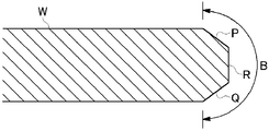
- 4A is a cross-sectional view showing a bevel portion of a so-called straight type substrate
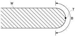
- FIG. 4B is a cross-sectional view showing a bevel portion of a so-called round type substrate.
- the bevel portion B includes an upper inclined portion (upper bevel portion) P, a lower inclined portion (lower bevel portion) Q, and a side portion (apex) R.
- the side portion R is the outermost edge portion of the substrate S, and thus the outermost edge portion is a surface (a line in the cross section).
- the bevel portion B is a portion having a curved section that is convex outward.
- the center point T in the thickness direction of the substrate S in the bevel portion B is the outermost edge, and thus the outermost edge is a line (a point in the cross section).
- the substrate cleaning roll is a roller having a rotation axis parallel to the surface of the substrate, the substrate cleaning roll cannot rub the bevel portion of the substrate S, and particles remain in the bevel portion. Therefore, in the conventional roll cleaning apparatus, a side roller having a rotation axis perpendicular to the surface of the substrate is provided separately from the substrate cleaning roll, and the side roller is rubbed against the side of the substrate, or the end of the substrate cleaning roll is
- the bevel part is washed by devising the shape (for example, refer to Patent Document 2).
- FIG. 5 is a diagram showing the overall configuration of the substrate cleaning apparatus disclosed in Patent Document 2.
- FIG. FIG. 6 is a side view showing a substrate cleaning roll and a substrate of the substrate cleaning apparatus of Patent Document 2.
- a pair of substrate cleaning rolls 2 a and 2 b can contact and retract on the upper surface (front surface) and lower surface (back surface) of the substrate S so as to sandwich the substrate S from above and below. Is arranged.
- the substrate cleaning rolls 2a and 2b are formed to be slightly thick at both ends. Thereby, as shown in FIG. 6, the substrate cleaning rolls 2a and 2b rub along the bevel portion of the substrate S at both ends of the substrate cleaning rolls 2a and 2b, and the bevel portion is cleaned.
- the substrate cleaning apparatus 1 includes a side roller 3 provided at a position where it does not interfere with the substrate cleaning rolls 2a and 2b.
- the side roller 3 has a columnar shape and rubs and cleans the outermost portion of the substrate S that does not reach the end of the substrate cleaning rolls 2a and 2b.
- the bevel portion of the substrate S can be cleaned by the substrate cleaning rolls 2 a and 2 b and the side roller 3.
- the substrate cleaning rolls 2a and 2b are not sufficient, and a side roller different from that is used. 3 is required. This is because the substrate cleaning rolls 2a and 2b cannot clean the outermost edge of the substrate S.
- the present technology has been made in view of the above problems, and an object of the present technology is to provide a substrate cleaning roll capable of cleaning the outermost edge of the substrate, a substrate cleaning apparatus using the substrate cleaning roll, and a substrate cleaning method.
- the substrate cleaning roll has a cylindrical shape, contacts the substrate so that the longitudinal direction thereof is parallel to the surface of the substrate, and rotates around the rotation axis in the longitudinal direction.
- the bevel cleaning section may have a trapezoidal shape in which a cross section by a virtual plane including the rotation axis includes the contact surface. With this configuration, the bevel cleaning section can be easily deformed so as to wrap around the peripheral bevel portion of the substrate.
- the substrate cleaning roll may be formed with a plurality of nodules that come into contact with the surface of the substrate when cleaning the surface of the substrate, and the bevel cleaning unit is higher than the nodules. It may be high. Also with this configuration, the bevel cleaning part can be easily deformed so as to wrap around the bevel part on the periphery of the substrate.
- the skin layer may be removed from the inclined surface.
- the bevel cleaning part can be easily deformed so as to wrap around the bevel part on the periphery of the substrate.
- a substrate cleaning apparatus includes a substrate holding unit that holds a substrate, a columnar shape, and is in contact with the substrate so that a longitudinal direction thereof is parallel to the surface of the substrate.
- the substrate cleaning roll for scrub cleaning the surface of the substrate by rotating around, the substrate cleaning roll on the surface of the substrate held by the substrate holding means, and the longitudinal direction on the surface of the substrate
- the at least one end side in the longitudinal direction is the outermost edge portion of the bevel portion at the periphery of the substrate when the substrate cleaning roll comes into contact with the substrate by the vertical drive mechanism It has a configuration having a bevel cleaning unit having an inclined surface that conflicting. Also with this configuration, the outermost edge of the bevel portion at the periphery of the substrate is cleaned by the bevel cleaning portion of the substrate cleaning roll.
- the substrate cleaning roll when the bevel portion on the periphery of the substrate has two inclined portions and a side portion therebetween, the substrate cleaning roll is held by the substrate holding means.
- the inclined surface When the substrate is pressed against the substrate by the vertical drive mechanism, the inclined surface may be deformed, and the inclined surface may come into contact with one of the inclined portion and the side portion of the substrate.
- the substrate cleaning roll when the bevel portion at the periphery of the substrate has a curved section that is convex outward, the substrate cleaning roll is attached to the substrate held by the substrate holding means.
- the inclined surface When pressed by the vertical drive mechanism, the inclined surface may be deformed, and the inclined surface may contact a portion between the surface of the substrate and the edge of the bevel portion.
- the two substrate cleaning rolls may be provided as two substrate cleaning rolls for cleaning the two surfaces of the substrate, respectively.
- one of the two substrate cleaning rolls comes into contact with an arbitrary portion of the bevel portion on the peripheral edge of the substrate, and the bevel portion can be scrub cleaned without a gap.
- the substrate cleaning roll having a cylindrical shape is rotated around the rotation axis in the longitudinal direction by holding and rotating the substrate, and the rotating substrate cleaning roll is rotated in the longitudinal direction.
- a substrate cleaning method for scrub cleaning the surface of the substrate by contacting the rotating substrate so as to be parallel to the surface of the substrate, when the substrate cleaning roll contacts the substrate
- the substrate cleaning roll has a configuration in which the edge of the bevel cleaning portion formed on at least one end side in the longitudinal direction comes into contact with the outermost edge of the bevel at the periphery of the substrate and cleans the outermost portion. ing. Also with this configuration, the outermost edge of the bevel portion at the periphery of the substrate is cleaned by the bevel cleaning portion of the substrate cleaning roll.
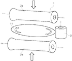
- FIG. 1 is a perspective view illustrating an outline of a cleaning device according to an embodiment of the present technology.
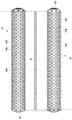
- FIG. 2 is a side view showing the upper substrate cleaning roll, the lower substrate cleaning roll, and the substrate of the substrate cleaning apparatus according to the embodiment of the present technology.
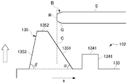
- FIG. 3A is an enlarged cross-sectional view showing one end of the scrub member of the lower substrate cleaning roll (retracted state) in the embodiment of the present technology.
- FIG. 3B is an enlarged cross-sectional view showing one end of the scrub member of the lower substrate cleaning roll (cleaned state) in the embodiment of the present technology.
- FIG. 4A is a cross-sectional view showing a bevel portion of a straight type substrate.
- FIG. 4B is a cross-sectional view showing a bevel portion of a round type substrate.
- FIG. 5 is a diagram showing an overall configuration of a conventional substrate cleaning apparatus.
- FIG. 6 is a side view showing a substrate cleaning roll and a substrate of a conventional substrate cleaning apparatus.
- FIG. 1 is a perspective view showing an outline of a substrate cleaning apparatus according to an embodiment of the present technology.
- the substrate cleaning apparatus 10 has a plurality of horizontally movable substrates (in FIG. 1) that support the peripheral portion of the substrate S and horizontally rotate the substrate S with the surface horizontal. 4) spindles 11 (substrate holding means), an upper substrate cleaning roll (roll sponge) 12 rotatably supported on a roll holder (not shown), and a lower substrate cleaning roll rotatably supported on a roll holder (not shown). (Roll sponge) 13.
- the upper substrate cleaning roll 12 and the lower substrate cleaning roll 13 have a cylindrical shape and extend in a long shape.
- the upper substrate cleaning roll 12 can be moved up and down with respect to the upper surface (front surface) of the substrate S by the roll holder, and the lower substrate cleaning roll 13 is lowered by the roll holder (lower surface ( It can be raised and lowered with respect to the back surface.
- the upper substrate cleaning roll 12 is rotated as indicated by an arrow F1 by a driving mechanism (rotation driving means) (not shown), and the lower substrate cleaning roll 13 is rotated as indicated by an arrow F2 by a driving mechanism (not shown).
- Two cleaning liquid supply nozzles 14 and 15 for supplying a cleaning liquid to the surface of the substrate S are disposed above the substrate S to be supported and rotated by the spindle 11.
- the cleaning liquid supply nozzle 14 is a nozzle that supplies a rinsing liquid (for example, ultrapure water) to the surface of the substrate S
- the cleaning liquid supply nozzle 15 is a nozzle that supplies a chemical liquid to the surface of the substrate S.
- the substrate cleaning apparatus 10 rotates (spins) the top 11a by positioning the peripheral edge of the substrate S in a fitting groove formed on the outer peripheral side of the top 11a provided on the spindle 11 and pressing it inwardly.
- the substrate S is rotated horizontally.
- two pieces 11a out of four pieces 11a give a rotational force to the substrate S, and the other two pieces 11a function as a bearing that receives the rotation of the substrate S.
- all the tops 11a may be coupled to the drive mechanism to apply a rotational force to the substrate S.
- the rinsing liquid is supplied from the cleaning liquid supply nozzle 14 to the surface of the substrate S, and the chemical liquid is supplied from the cleaning liquid supply nozzle 15 to the surface of the substrate S.
- the roll 12 is lowered by a vertical driving mechanism (not shown) and brought into contact with the surface of the rotating substrate S, while the lower substrate cleaning roll 13 is rotated and raised by a vertical driving mechanism (not shown).
- a vertical driving mechanism not shown
- the surface of the substrate S is scrubbed by the upper substrate cleaning roll 12 in the presence of the cleaning liquid (rinsing liquid and chemical liquid).
- Each of the upper and lower drive cleaning mechanisms of the upper substrate cleaning roll 12 and the lower substrate cleaning roll 13 may move the upper substrate cleaning roll 12 and the lower substrate cleaning roll 13 up and down in a direction perpendicular to the surface of the substrate S. It may be moved up and down in an oblique direction with respect to the surface of the substrate S, may be pivoted from a certain point, or may be a combination of these operations.
- the lengths of the upper substrate cleaning roll 12 and the lower substrate cleaning roll 13 are both set slightly longer than the diameter of the substrate S.
- Upper substrate cleaning roll 12 and the lower substrate cleaning roll 13 is parallel to the central axis (rotation axis) O 1 and O 2 is, the central axis (i.e., center of rotation) O S substantially orthogonal (substrate S on the surface of the substrate S And is disposed so as to extend over the entire length of the diameter of the substrate S. Thereby, the entire front and back surfaces of the substrate S are simultaneously cleaned.
- the upper substrate cleaning roll 12 and the lower substrate cleaning roll 13 are parallel across the substrate S, but the upper substrate cleaning roll 12 and the lower substrate cleaning roll 13 are They may be parallel to the surface of the substrate S and have a predetermined angle with each other.
- the substrate cleaning apparatus 10 may clean the substrate S having a diameter of 450 mm, may clean the substrate S having a diameter of 300 mm, or may clean the substrate S having a smaller diameter.
- the upper substrate cleaning roll 12 and the lower substrate cleaning roll 13 may have the same length as the diameter of the substrate S to be cleaned by the substrate cleaning apparatus 10.
- FIG. 2 is a side view showing the upper substrate cleaning roll 12 and the lower substrate cleaning roll 13 and the substrate S of the substrate cleaning apparatus 10.
- the upper substrate cleaning roll 12 and the lower substrate cleaning roll 13 (hereinafter collectively referred to simply as “substrate cleaning roll”) are fixed to the cylindrical core members 121 and 131 and the outer peripheral surfaces of the core members 121 and 131. It consists of cylindrical scrub members 122 and 132.
- the scrub members 122 and 132 are porous members made of sponge, PVA, or the like.
- the scrub members 122 and 132 have a shape in which a plurality of nodules 124 and 134 protrude from base surfaces 123 and 133 that are cylindrical surfaces.
- the plurality of nodules 124 and 134 are arranged on a plurality of straight lines arranged in parallel with the rotation axis direction (longitudinal direction) a of the substrate cleaning roll. These straight lines are separated at equal intervals in the circumferential direction of the substrate cleaning roll.
- the nodules 124 and 134 adjacent in the circumferential direction are shifted from each other by a half pitch in the rotation axis direction. Therefore, the plurality of nodules 124 and 134 are arranged at equiangular intervals in the circumferential direction.
- positioning of a some nodule is only an example, and other arrangement
- nodules 124 and 134 and a bevel cleaning section are provided on one end of the scrub member 122 of the upper substrate cleaning roll 12 (right end in FIG. 2) and one end of the scrub member 132 of the lower substrate cleaning roll 13 (left end in FIG. 2).
- Edge nodules 125 and 135 are alternately formed in the circumferential direction.
- the edge nodules 125 and 135 are formed on the same straight line as the nodules 124 and 134 so as to surround the ends of the scrub members 122 and 132.
- the positions and intervals may be arbitrary.
- the edge nodules 125 and 135 and the nodules 124 and 134 are alternately formed.
- one edge nodule 125 and 135 is formed every two or more nodules 124 and 134.
- one nodule 124, 134 may be formed every two or more edge nodules 125, 135.
- the outermost nodules 124 and 134 provided between the edge nodules 125 and 135 are such that the surfaces thereof are the edges of the planar portion of the upper surface of the substrate S (the boundary between the upper surface and the bevel portion) and the substrate S.
- the lower surface of the lower surface of the substrate S is formed at a position in contact with the edge of the flat surface portion (the boundary between the lower surface and the bevel portion). It is formed at a position in contact with the edge of the portion (boundary between the upper surface and the bevel portion) and the edge of the flat portion of the lower surface of the substrate S (boundary between the lower surface and the bevel portion).
- 3A and 3B are cross-sectional views of a virtual plane including a rotation axis of the lower substrate cleaning roll 13, showing one end (left end in FIG. 2) of the scrub member 132 of the lower substrate cleaning roll 13 in an enlarged manner. Since one end of the upper substrate cleaning roll 12 (the right end in FIG. 2) is rotationally symmetric with the configuration shown in FIGS. 3A and 3B, with the description of the lower substrate cleaning roll 13 with reference to FIGS. 3A and 3B, The description of the upper substrate cleaning roll 12 is omitted.
- FIG. 3A shows a retracted state in which the substrate S is not in contact with the lower substrate cleaning roll 13 and FIG. 3B shows a cleaning state in which the substrate S is in contact with the lower substrate cleaning roll 13.
- FIG. 3B shows a cleaning state in which the substrate S is in contact with the lower substrate cleaning roll 13.
- 3A and 3B the substrate S is held by a plurality of tops 11a (see FIG. 1).
- 3A and 3B show an example in which the substrate S is a so-called straight type.
- the lower substrate cleaning roll 13 is raised by the vertical drive mechanism from the state of FIG. 3A and contacts the substrate S as shown in FIG. 3B.
- an arrow a indicates the longitudinal direction (rotational axis direction) of the lower substrate cleaning roll 13.
- the edge nodule 135 has a shape in which a cross section by a virtual plane including the rotation axis of the lower substrate cleaning roll 13 is a trapezoidal shape. That is, the edge nodule 135 includes a substrate-side inclined surface 1351, a top surface 1352, and an outer inclined surface 1353. Note that the edge nodule 135 may not have the top surface 1352 and may have a triangular cross section, and the top surface 1352 may be a curved surface.
- the edge nodule 135 is higher in height than the nodule 134. Further, the edge nodule 135 is formed such that the substrate side inclined surface 1351 covers the entire lower inclined portion Q of the bevel portion B of the substrate S in the radial direction of the substrate S (longitudinal direction a of the lower substrate cleaning roll 13). And provided at such a position. Therefore, when the substrate S comes into contact with the scrub member 132 of the lower substrate cleaning roll 13, the side portion R that is the outermost portion of the substrate S comes into contact with the substrate-side inclined surface 1351 of the edge nodule 135.
- the first contact portion C of the edge nodule 135 that first comes into contact with the substrate S when the lower substrate cleaning roll 13 rises and contacts the substrate S is on the substrate-side inclined surface 1351 and from the top surface 1341 of the nodule 134. Is also in a high position.
- the angle ⁇ formed by the substrate-side inclined surface 1351 with the base surface 133 and the angle ⁇ formed by the outer inclined surface 1353 with the base surface 133 are both acute angles. Further, ⁇ and ⁇ have a relationship of ⁇ ⁇ , that is, the substrate-side inclined surface 1351 has a gentler inclination than the outer inclined surface 1353.
- the lower substrate cleaning roll 13 is raised by the vertical drive mechanism of the substrate cleaning apparatus 10. As shown in FIG. 3B, the lower substrate cleaning roll 13 is raised until the nodule 134 is further crushed by the substrate S after the top surface 1341 of the nodule 134 contacts the surface of the substrate S. Therefore, the edge nodule 135 is also deformed by further raising of the lower substrate cleaning roll 13 after contacting the bevel portion B of the substrate S at the first contact location C of the substrate side inclined surface 1351.
- the nodule 134 is pushed and crushed by the surface of the substrate S, and the edge nodule 135 is crushed downward by the bevel portion B of the substrate S at the substrate-side inclined surface 1351.
- the top surface 1352 and the outer inclined surface 1353 of the edge nodule 135 are slightly inclined inward, and the bevel portion B of the substrate S bites into the substrate-side inclined surface 1351, so that the substrate-side inclined surface 1351 is It contacts the entire lower sloped portion Q of S and the entire side portion R which is the outermost portion.
- the edge nodule 135 is deformed so that the substrate-side inclined surface 1351 is along the lower inclined portion Q and the side portion R of the substrate S. At this time, the substrate-side inclined surface 1351 is in contact with the lower inclined portion Q over the entire radial direction of the substrate S, and is in contact with the side portion R over the entire vertical direction.
- the height of the nodule 134 is, for example, 3.0 to 4.5 mm, and the pushing amount of the nodule 134 by the substrate S in the cleaning state (the collapsing amount of the nodule 134) is, for example, 0.5 to 2.0 mm. Further, the height of the edge nodule 135 is, for example, 4.0 mm to 7.0 mm, the inclination angle ⁇ is desirably 40 to 70 degrees, and the inclination angle ⁇ is desirably 80 to 90 degrees.
- the design of the scrub member 132 is not limited to these.
- the scrub member 132 is a porous member, but generally, a layer called a skin layer with a relatively small gap is formed on the surface thereof.
- this skin layer is removed at least on the substrate-side inclined surface 1351, that is, the surface in contact with the substrate S. Therefore, the deformation
- the edge nodule 135 may be designed such that the edge nodule 135 contacts the entire bevel part B including the upper bevel part P.
- the edge nodule 135 of the lower substrate cleaning roll 13 has been described above, as described above, the upper substrate cleaning roll 12 is also formed with the same edge nodule 125 at one end, and the upper substrate cleaning roll 12 is moved up and down. Is lowered toward the substrate S, the edge nodule 125 is crushed by the bevel portion B of the substrate S and comes into contact with the upper inclined portion P and the side portion R of the bevel portion B so as to wrap. At this time, the substrate-side inclined surface of the edge nodule 125 is in contact with the upper inclined portion P over the entire radial direction of the substrate S, and is in contact with the side portion R over the entire vertical direction.
- the upper substrate cleaning roll 12 is retracted upward by the vertical drive mechanism, and the lower substrate cleaning roll 13 is retracted downward by the vertical drive mechanism.
- this retracted state cleaning preparation state
- the substrate S is held by the rollers 11a of the plurality of spindles 11, and the spindle 11 is driven to rotate, whereby the substrate S is horizontally rotated around its center.
- the cleaning liquid is supplied from the cleaning liquid supply nozzles 14 and 15 to the surface of the substrate S, respectively.
- the upper substrate cleaning roll 12 is rotationally driven around the rotational axis in the longitudinal direction by the rotational drive mechanism
- the lower substrate cleaning roll 12 is rotationally driven around the rotational axis in the longitudinal direction by the rotational drive mechanism.
- the rotating upper substrate cleaning roll 12 is lowered toward the substrate S by the vertical drive mechanism until the nodule 124 is crushed by the substrate S, whereby the bevel portion B of the substrate S is edged.
- the bevel part B of the substrate S is made to bite into the substrate-side inclined surface of the nodule 125, and the rotating lower substrate cleaning roll 13 is raised toward the substrate S by the vertical drive mechanism until the nodule 134 is crushed by the substrate S.
- the edge nodule 135 is bitten into the substrate-side inclined surface 1351.
- the upper substrate cleaning roll 12 and the lower substrate cleaning roll 13 are parallel to each other in the longitudinal direction, and the edge nodules 125 and 135 are provided on opposite sides. Therefore, even in the cleaning state, the edge nodule 125 of the upper substrate cleaning roll 12 and the edge nodule 135 of the lower substrate cleaning roll 13 do not interfere (contact) each other.
- the portions of the scrub members 122 and 132 that come into contact with the substrate S are the upper substrate cleaning roll 12 and the lower substrate cleaning roll 13.
- the movement direction is provided by the rotation of the cleaning roll 13 and the surface portion of the substrate S that is in contact with the portions of the scrub members 122 and 132 is provided on the follow side (the left front side in FIG. 1) that coincides with the direction of movement by the rotation of the substrate S.
- it may be provided on the counter side (the back right side in FIG. 1) opposite to that.
- the edge nodule 125 of the upper substrate cleaning roll 12 is in contact with the entire side portion R in the vertical direction
- the edge nodule 135 of the lower substrate cleaning roll 13 is in the vertical direction of the side portion R. Since it is in contact with the whole, the entire surface of the side portion R is in contact with both the edge nodule 125 and the edge nodule 135 and is rubbed.
- edge nodules 125 and 135 are not necessarily in contact with the side portion R over the entire vertical direction. If the portion is rubbed by at least one of the edge nodule 125 and the edge nodule 135, the entire bevel portion B can be cleaned.
- the edge nodule 125 and the edge nodule 135 have the same shape, the edge nodule 125 contacts at least from the upper side to the center of the substrate S in the thickness direction (the upper half of the upper inclined portion P and the upper half of the side portion R), and the edge If the nodule 135 is in contact with at least the lower side to the center of the substrate S in the thickness direction (the lower half of the lower inclined portion Q and the lower side R), the entire bevel portion B can be cleaned.
- the edge nodule 125 wraps at least the bevel portion B above the outermost edge T, and the edge nodule 135 is at least the outermost edge T.
- the entire bevel portion B can be cleaned by the cooperation of the upper substrate cleaning roll 12 and the lower substrate cleaning roll 13.
- the substrate cleaning apparatus 10 may further include a conventional side roller (see FIG. 5) in addition to the upper substrate cleaning roll 12 and the lower substrate cleaning roll 13 having the above-described configuration. This enhances the cleaning of the bevel portion B, particularly the outermost edge portion and the periphery thereof.
- the substrate cleaning apparatus 10 has a pair of substrate cleaning rolls above and below the substrate S. However, only one of the upper substrate cleaning roll 12 and the lower substrate cleaning roll 13 is provided. Also good.
- the edge nodules 125 and 135 are formed only on one end side in the upper substrate cleaning roll 12 and the lower substrate cleaning roll 13, but edge nodules may be formed on both ends.
- the upper substrate cleaning roll 12 and the lower substrate cleaning roll 13 are provided in parallel to each other on the front side and the back side of the substrate S, and the edge nodules 125 of the upper substrate cleaning roll 12 are provided.
- the edge nodule 135 of the lower substrate cleaning roll 13 and the edge nodule 135 of the lower substrate cleaning roll 13 are formed on the same side. Also good.
- a plurality of edge nodules 125 and 135 are provided over the entire circumference of the substrate cleaning roll. However, these may be integrally formed over the entire circumference. In this case, the portions of the scrub member 122 and the scrub member 132 that bite into the bevel portion B of the substrate S become the bevel cleaning portion.
- the cross-sectional shape of the bevel cleaning section may be the same as that shown in FIGS. 3A and 3B.
- the present technology has an effect that the outermost edge of the bevel portion on the periphery of the substrate can be cleaned by the bevel cleaning portion of the substrate cleaning roll, and the substrate cleaning roll for scrub cleaning the surface of the substrate, and the substrate using the same. It is useful as a substrate cleaning apparatus for cleaning.
- Substrate cleaning device 11 Spindle (substrate holding means) 12 Upper substrate cleaning roll 13 Lower substrate cleaning roll 122, 132 Scrub member 124, 134 Nodule 125, 135 Edge nodule (Bevel cleaning unit)
Landscapes
- Chemical & Material Sciences (AREA)
- Chemical Kinetics & Catalysis (AREA)
- General Chemical & Material Sciences (AREA)
- Cleaning Or Drying Semiconductors (AREA)
Abstract
Description
11 スピンドル(基板保持手段)
12 上部基板洗浄ロール
13 下部基板洗浄ロール
122、132 スクラブ部材
124、134 ノジュール
125、135 エッジノジュール(ベベル洗浄部)
Claims (9)
- 円柱形状を有し、長手方向が基板の表面と平行になるように前記基板に接触して前記長手方向の回転軸周りに回転することで前記基板の表面をスクラブ洗浄するための基板洗浄ロールであって、
前記長手方向の少なくとも一端側に、前記基板洗浄ロールが前記基板と接触して前記基板の表面を洗浄するときに前記基板の周縁のベベル部の最縁部に抵触する傾斜面を有するベベル洗浄部を備えたことを特徴とする基板洗浄ロール。 - 前記ベベル洗浄部は、前記回転軸を含む仮想平面による断面が前記接触面を含む台形形状を有することを特徴とする請求項1に記載の基板洗浄ロール。
- 前記基板洗浄ロールには、前記基板の表面を洗浄する際に前記基板の表面と接触する複数のノジュールが形成されており、
前記ベベル洗浄部は、前記ノジュールより高さが高いことを特徴とする請求項1又は2に記載の基板洗浄ロール。 - 前記傾斜面は、スキン層が除去されていることを特徴とする請求項1ないし3のいずれか一項に記載の基板洗浄ロール。
- 基板を保持する基板保持手段と、
円柱形状を有し、長手方向が基板の表面と平行になるように前記基板に接触して前記長手方向の回転軸周りに回転することで前記基板の表面をスクラブ洗浄するための基板洗浄ロールと、
前記基板洗浄ロールを、前記基板保持手段によって保持された前記基板の表面に、前記長手方向が前記基板の表面に水平になるように押し付ける上下駆動機構と、
前記上下駆動機構によって前記基板の表面に押し付けられた前記基板洗浄ロールを前記長手方向の回転軸周りに回転させる回転駆動機構と、
を備え、
前記基板洗浄ロールは、前記長手方向の少なくとも一端側に、前記基板洗浄ロールが前記上下駆動機構によって前記基板と接触したときに前記基板の周縁のベベル部の最縁部に抵触する傾斜面を有するベベル洗浄部を備えたことを特徴とする基板洗浄装置。 - 前記基板の周縁の前記ベベル部は、2つの傾斜部とその間の側部とを有し、
前記基板洗浄ロールは、前記基板保持手段によって保持された前記基板に、前記上下駆動機構によって押し付けられたときに、前記傾斜面が変形して、前記傾斜面が前記基板の1つの前記傾斜部と前記側部とに接触することを特徴とする請求項5に記載の基板洗浄装置。 - 前記基板の周縁の前記ベベル部は、外側に凸の湾曲した断面を有し、
前記基板洗浄ロールは、前記基板保持手段によって保持された前記基板に、前記上下駆動機構によって押し付けられたときに、前記傾斜面が変形して、前記傾斜面が前記基板の前記表面から前記ベベル部の最縁部までの間の部分に接触することを特徴とする請求項5に記載の基板洗浄装置。 - 前記基板の2つ表面をそれぞれ洗浄する2つの基板洗浄ロールとして、前記基板洗浄ロールを2つ備えたことを特徴とする請求項5なしい7のいずれか一項に記載の基板洗浄装置。
- 基板を保持して回転させ、
円柱形状を有する基板洗浄ロールをその長手方向の回転軸周りに回転させ、
回転する前記基板洗浄ロールを、前記長手方向が前記基板の表面と平行になるように、回転する前記基板に接触させることで、前記基板の表面をスクラブ洗浄する基板洗浄方法であって、
前記基板洗浄ロールが前記基板と接触したときに、前記基板洗浄ロールが、前記長手方向の少なくとも一端側に形成されたベベル洗浄部の傾斜面で、前記基板の周縁のベベル部の最縁部に接触して前記最縁部を洗浄することを特徴とする基板洗浄方法。
Priority Applications (6)
| Application Number | Priority Date | Filing Date | Title |
|---|---|---|---|
| CN201580058746.0A CN107078046B (zh) | 2014-10-31 | 2015-10-20 | 基板清洗辊、基板清洗装置及基板清洗方法 |
| JP2016556207A JP6377758B2 (ja) | 2014-10-31 | 2015-10-20 | 基板洗浄ロール、基板洗浄装置、及び基板洗浄方法 |
| KR1020177014701A KR20170077210A (ko) | 2014-10-31 | 2015-10-20 | 기판 세정 롤, 기판 세정 장치, 및 기판 세정 방법 |
| US15/522,596 US10892173B2 (en) | 2014-10-31 | 2015-10-20 | Substrate cleaning roll, substrate cleaning apparatus, and substrate cleaning method |
| MYPI2017701322A MY182464A (en) | 2014-10-31 | 2015-10-20 | Substrate cleaning roll, substrate cleaning apparatus, and substrate cleaning method |
| SG11201703375WA SG11201703375WA (en) | 2014-10-31 | 2015-10-20 | Substrate cleaning roll, substrate cleaning apparatus, and substrate cleaning method |
Applications Claiming Priority (2)
| Application Number | Priority Date | Filing Date | Title |
|---|---|---|---|
| JP2014-223728 | 2014-10-31 | ||
| JP2014223728 | 2014-10-31 |
Publications (1)
| Publication Number | Publication Date |
|---|---|
| WO2016067563A1 true WO2016067563A1 (ja) | 2016-05-06 |
Family
ID=55856930
Family Applications (1)
| Application Number | Title | Priority Date | Filing Date |
|---|---|---|---|
| PCT/JP2015/005280 Ceased WO2016067563A1 (ja) | 2014-10-31 | 2015-10-20 | 基板洗浄ロール、基板洗浄装置、及び基板洗浄方法 |
Country Status (8)
| Country | Link |
|---|---|
| US (1) | US10892173B2 (ja) |
| JP (1) | JP6377758B2 (ja) |
| KR (1) | KR20170077210A (ja) |
| CN (1) | CN107078046B (ja) |
| MY (1) | MY182464A (ja) |
| SG (1) | SG11201703375WA (ja) |
| TW (1) | TWI669158B (ja) |
| WO (1) | WO2016067563A1 (ja) |
Cited By (4)
| Publication number | Priority date | Publication date | Assignee | Title |
|---|---|---|---|---|
| KR20200018279A (ko) | 2018-08-09 | 2020-02-19 | 가부시키가이샤 에바라 세이사꾸쇼 | 기판용 세정구, 기판 세정 장치, 기판 처리 장치, 기판 처리 방법 및 기판용 세정구의 제조 방법 |
| JP2020145256A (ja) * | 2019-03-05 | 2020-09-10 | 株式会社ディスコ | 加工装置及び洗浄方法 |
| JP2021005738A (ja) * | 2020-10-15 | 2021-01-14 | 株式会社荏原製作所 | 基板洗浄装置および基板洗浄方法ならびに基板洗浄装置用のロールスポンジ |
| KR20210147853A (ko) | 2019-04-09 | 2021-12-07 | 가부시키가이샤 에바라 세이사꾸쇼 | 기판 처리 장치 및 기판 세정 방법 |
Families Citing this family (3)
| Publication number | Priority date | Publication date | Assignee | Title |
|---|---|---|---|---|
| CN107971261B (zh) * | 2017-11-23 | 2021-03-02 | Tcl华星光电技术有限公司 | 清洁装置 |
| CN115440576B (zh) * | 2022-09-30 | 2025-09-09 | 中国科学院光电技术研究所 | 衬底上光刻结构的返工清洗方法 |
| CN116787253A (zh) * | 2023-08-18 | 2023-09-22 | 浙江求是半导体设备有限公司 | 驱动机构、晶片表面清理设备及抛光设备 |
Citations (3)
| Publication number | Priority date | Publication date | Assignee | Title |
|---|---|---|---|---|
| JPH11283952A (ja) * | 1998-03-30 | 1999-10-15 | Shibaura Mechatronics Corp | ブラシ洗浄装置 |
| JP2002313767A (ja) * | 2001-04-17 | 2002-10-25 | Ebara Corp | 基板処理装置 |
| JP2013520803A (ja) * | 2010-02-22 | 2013-06-06 | インテグリス・インコーポレーテッド | Cmp後の洗浄ブラシ |
Family Cites Families (9)
| Publication number | Priority date | Publication date | Assignee | Title |
|---|---|---|---|---|
| WO1998020987A1 (en) | 1996-11-08 | 1998-05-22 | Kanebo Limited | Sponge roller for cleaning |
| US6299698B1 (en) * | 1998-07-10 | 2001-10-09 | Applied Materials, Inc. | Wafer edge scrubber and method |
| JP2003163196A (ja) | 2001-11-28 | 2003-06-06 | Kaijo Corp | 半導体基板の基板洗浄装置及び洗浄方法 |
| EP1973152A4 (en) * | 2006-01-10 | 2010-09-29 | Tokyo Electron Ltd | SUBSTRATE CLEANING DEVICE, SUBSTRATE CLEANING PROCESS, SUBSTRATE TREATMENT SYSTEM AND RECORDING MEDIUM |
| JP2008142590A (ja) * | 2006-12-06 | 2008-06-26 | Speedfam Clean System Co Ltd | スクラブ洗浄装置 |
| US8578953B2 (en) * | 2006-12-20 | 2013-11-12 | Tokyo Electron Limited | Substrate cleaning apparatus, substrate cleaning method, and computer-readable storage medium |
| US20100043160A1 (en) * | 2008-08-20 | 2010-02-25 | United Microelectronics Corp. | Wafer cleaning roller |
| JP5645752B2 (ja) * | 2011-05-25 | 2014-12-24 | 株式会社荏原製作所 | 基板洗浄方法及びロール洗浄部材 |
| JP6212253B2 (ja) * | 2012-11-15 | 2017-10-11 | 株式会社荏原製作所 | 基板洗浄装置及び基板洗浄方法 |
-
2015
- 2015-10-20 CN CN201580058746.0A patent/CN107078046B/zh active Active
- 2015-10-20 MY MYPI2017701322A patent/MY182464A/en unknown
- 2015-10-20 KR KR1020177014701A patent/KR20170077210A/ko not_active Ceased
- 2015-10-20 WO PCT/JP2015/005280 patent/WO2016067563A1/ja not_active Ceased
- 2015-10-20 US US15/522,596 patent/US10892173B2/en active Active
- 2015-10-20 SG SG11201703375WA patent/SG11201703375WA/en unknown
- 2015-10-20 JP JP2016556207A patent/JP6377758B2/ja active Active
- 2015-10-26 TW TW104135057A patent/TWI669158B/zh active
Patent Citations (3)
| Publication number | Priority date | Publication date | Assignee | Title |
|---|---|---|---|---|
| JPH11283952A (ja) * | 1998-03-30 | 1999-10-15 | Shibaura Mechatronics Corp | ブラシ洗浄装置 |
| JP2002313767A (ja) * | 2001-04-17 | 2002-10-25 | Ebara Corp | 基板処理装置 |
| JP2013520803A (ja) * | 2010-02-22 | 2013-06-06 | インテグリス・インコーポレーテッド | Cmp後の洗浄ブラシ |
Cited By (9)
| Publication number | Priority date | Publication date | Assignee | Title |
|---|---|---|---|---|
| KR20200018279A (ko) | 2018-08-09 | 2020-02-19 | 가부시키가이샤 에바라 세이사꾸쇼 | 기판용 세정구, 기판 세정 장치, 기판 처리 장치, 기판 처리 방법 및 기판용 세정구의 제조 방법 |
| US11424138B2 (en) | 2018-08-09 | 2022-08-23 | Ebara Corporation | Substrate cleaning tool, substrate cleaning apparatus, substrate processing apparatus, substrate processing method, and method of manufacturing substrate cleaning tool |
| JP2020145256A (ja) * | 2019-03-05 | 2020-09-10 | 株式会社ディスコ | 加工装置及び洗浄方法 |
| JP7320358B2 (ja) | 2019-03-05 | 2023-08-03 | 株式会社ディスコ | 加工装置及び洗浄方法 |
| KR20210147853A (ko) | 2019-04-09 | 2021-12-07 | 가부시키가이샤 에바라 세이사꾸쇼 | 기판 처리 장치 및 기판 세정 방법 |
| JP2021005738A (ja) * | 2020-10-15 | 2021-01-14 | 株式会社荏原製作所 | 基板洗浄装置および基板洗浄方法ならびに基板洗浄装置用のロールスポンジ |
| JP2022031560A (ja) * | 2020-10-15 | 2022-02-18 | 株式会社荏原製作所 | 基板洗浄装置および基板洗浄方法ならびに基板洗浄装置用のロールスポンジ |
| JP7093390B2 (ja) | 2020-10-15 | 2022-06-29 | 株式会社荏原製作所 | 基板洗浄装置 |
| JP7315648B2 (ja) | 2020-10-15 | 2023-07-26 | 株式会社荏原製作所 | 基板洗浄装置および基板洗浄方法ならびに基板洗浄装置用のロールスポンジ |
Also Published As
| Publication number | Publication date |
|---|---|
| TW201628724A (zh) | 2016-08-16 |
| JPWO2016067563A1 (ja) | 2017-06-01 |
| MY182464A (en) | 2021-01-25 |
| CN107078046A (zh) | 2017-08-18 |
| TWI669158B (zh) | 2019-08-21 |
| SG11201703375WA (en) | 2017-05-30 |
| US10892173B2 (en) | 2021-01-12 |
| US20170316959A1 (en) | 2017-11-02 |
| CN107078046B (zh) | 2020-11-27 |
| JP6377758B2 (ja) | 2018-08-22 |
| KR20170077210A (ko) | 2017-07-05 |
Similar Documents
| Publication | Publication Date | Title |
|---|---|---|
| JP6377758B2 (ja) | 基板洗浄ロール、基板洗浄装置、及び基板洗浄方法 | |
| JP6366544B2 (ja) | 洗浄装置及びロール洗浄部材 | |
| US11642704B2 (en) | Roll-type processing member, pencil-type processing member, and substrate processing apparatus including any one of these | |
| JP5886224B2 (ja) | 基板洗浄方法 | |
| JP5645752B2 (ja) | 基板洗浄方法及びロール洗浄部材 | |
| KR102661661B1 (ko) | 기판 세정 장치 | |
| JP2010212295A (ja) | 基板洗浄装置および基板洗浄方法 | |
| KR20130007467A (ko) | 기판 세정 방법 | |
| CN111048442B (zh) | 基板清洗部件及基板清洗装置 | |
| JP2007022866A (ja) | 円盤状ガラス基板の洗浄方法および磁気ディスク | |
| KR102171900B1 (ko) | 기판 세정 장치 | |
| CN120834041A (zh) | 晶片的清洗方法以及清洗装置 |
Legal Events
| Date | Code | Title | Description |
|---|---|---|---|
| 121 | Ep: the epo has been informed by wipo that ep was designated in this application |
Ref document number: 15854715 Country of ref document: EP Kind code of ref document: A1 |
|
| ENP | Entry into the national phase |
Ref document number: 2016556207 Country of ref document: JP Kind code of ref document: A |
|
| WWE | Wipo information: entry into national phase |
Ref document number: 15522596 Country of ref document: US |
|
| WWE | Wipo information: entry into national phase |
Ref document number: 11201703375W Country of ref document: SG |
|
| NENP | Non-entry into the national phase |
Ref country code: DE |
|
| ENP | Entry into the national phase |
Ref document number: 20177014701 Country of ref document: KR Kind code of ref document: A |
|
| 122 | Ep: pct application non-entry in european phase |
Ref document number: 15854715 Country of ref document: EP Kind code of ref document: A1 |