WO2016067535A1 - 駐車支援装置 - Google Patents
駐車支援装置 Download PDFInfo
- Publication number
- WO2016067535A1 WO2016067535A1 PCT/JP2015/005170 JP2015005170W WO2016067535A1 WO 2016067535 A1 WO2016067535 A1 WO 2016067535A1 JP 2015005170 W JP2015005170 W JP 2015005170W WO 2016067535 A1 WO2016067535 A1 WO 2016067535A1
- Authority
- WO
- WIPO (PCT)
- Prior art keywords
- vehicle
- display
- parking
- image
- line
- Prior art date
- Legal status (The legal status is an assumption and is not a legal conclusion. Google has not performed a legal analysis and makes no representation as to the accuracy of the status listed.)
- Ceased
Links
Images







Classifications
-
- G—PHYSICS
- G06—COMPUTING OR CALCULATING; COUNTING
- G06V—IMAGE OR VIDEO RECOGNITION OR UNDERSTANDING
- G06V20/00—Scenes; Scene-specific elements
- G06V20/50—Context or environment of the image
- G06V20/56—Context or environment of the image exterior to a vehicle by using sensors mounted on the vehicle
- G06V20/588—Recognition of the road, e.g. of lane markings; Recognition of the vehicle driving pattern in relation to the road
-
- B—PERFORMING OPERATIONS; TRANSPORTING
- B60—VEHICLES IN GENERAL
- B60K—ARRANGEMENT OR MOUNTING OF PROPULSION UNITS OR OF TRANSMISSIONS IN VEHICLES; ARRANGEMENT OR MOUNTING OF PLURAL DIVERSE PRIME-MOVERS IN VEHICLES; AUXILIARY DRIVES FOR VEHICLES; INSTRUMENTATION OR DASHBOARDS FOR VEHICLES; ARRANGEMENTS IN CONNECTION WITH COOLING, AIR INTAKE, GAS EXHAUST OR FUEL SUPPLY OF PROPULSION UNITS IN VEHICLES
- B60K35/00—Instruments specially adapted for vehicles; Arrangement of instruments in or on vehicles
- B60K35/10—Input arrangements, i.e. from user to vehicle, associated with vehicle functions or specially adapted therefor
-
- B—PERFORMING OPERATIONS; TRANSPORTING
- B60—VEHICLES IN GENERAL
- B60K—ARRANGEMENT OR MOUNTING OF PROPULSION UNITS OR OF TRANSMISSIONS IN VEHICLES; ARRANGEMENT OR MOUNTING OF PLURAL DIVERSE PRIME-MOVERS IN VEHICLES; AUXILIARY DRIVES FOR VEHICLES; INSTRUMENTATION OR DASHBOARDS FOR VEHICLES; ARRANGEMENTS IN CONNECTION WITH COOLING, AIR INTAKE, GAS EXHAUST OR FUEL SUPPLY OF PROPULSION UNITS IN VEHICLES
- B60K35/00—Instruments specially adapted for vehicles; Arrangement of instruments in or on vehicles
- B60K35/20—Output arrangements, i.e. from vehicle to user, associated with vehicle functions or specially adapted therefor
- B60K35/21—Output arrangements, i.e. from vehicle to user, associated with vehicle functions or specially adapted therefor using visual output, e.g. blinking lights or matrix displays
- B60K35/22—Display screens
-
- B—PERFORMING OPERATIONS; TRANSPORTING
- B60—VEHICLES IN GENERAL
- B60K—ARRANGEMENT OR MOUNTING OF PROPULSION UNITS OR OF TRANSMISSIONS IN VEHICLES; ARRANGEMENT OR MOUNTING OF PLURAL DIVERSE PRIME-MOVERS IN VEHICLES; AUXILIARY DRIVES FOR VEHICLES; INSTRUMENTATION OR DASHBOARDS FOR VEHICLES; ARRANGEMENTS IN CONNECTION WITH COOLING, AIR INTAKE, GAS EXHAUST OR FUEL SUPPLY OF PROPULSION UNITS IN VEHICLES
- B60K35/00—Instruments specially adapted for vehicles; Arrangement of instruments in or on vehicles
- B60K35/50—Instruments characterised by their means of attachment to or integration in the vehicle
-
- B—PERFORMING OPERATIONS; TRANSPORTING
- B60—VEHICLES IN GENERAL
- B60K—ARRANGEMENT OR MOUNTING OF PROPULSION UNITS OR OF TRANSMISSIONS IN VEHICLES; ARRANGEMENT OR MOUNTING OF PLURAL DIVERSE PRIME-MOVERS IN VEHICLES; AUXILIARY DRIVES FOR VEHICLES; INSTRUMENTATION OR DASHBOARDS FOR VEHICLES; ARRANGEMENTS IN CONNECTION WITH COOLING, AIR INTAKE, GAS EXHAUST OR FUEL SUPPLY OF PROPULSION UNITS IN VEHICLES
- B60K35/00—Instruments specially adapted for vehicles; Arrangement of instruments in or on vehicles
- B60K35/60—Instruments characterised by their location or relative disposition in or on vehicles
-
- B—PERFORMING OPERATIONS; TRANSPORTING
- B60—VEHICLES IN GENERAL
- B60R—VEHICLES, VEHICLE FITTINGS, OR VEHICLE PARTS, NOT OTHERWISE PROVIDED FOR
- B60R1/00—Optical viewing arrangements; Real-time viewing arrangements for drivers or passengers using optical image capturing systems, e.g. cameras or video systems specially adapted for use in or on vehicles
- B60R1/20—Real-time viewing arrangements for drivers or passengers using optical image capturing systems, e.g. cameras or video systems specially adapted for use in or on vehicles
- B60R1/22—Real-time viewing arrangements for drivers or passengers using optical image capturing systems, e.g. cameras or video systems specially adapted for use in or on vehicles for viewing an area outside the vehicle, e.g. the exterior of the vehicle
- B60R1/23—Real-time viewing arrangements for drivers or passengers using optical image capturing systems, e.g. cameras or video systems specially adapted for use in or on vehicles for viewing an area outside the vehicle, e.g. the exterior of the vehicle with a predetermined field of view
- B60R1/26—Real-time viewing arrangements for drivers or passengers using optical image capturing systems, e.g. cameras or video systems specially adapted for use in or on vehicles for viewing an area outside the vehicle, e.g. the exterior of the vehicle with a predetermined field of view to the rear of the vehicle
-
- B—PERFORMING OPERATIONS; TRANSPORTING
- B62—LAND VEHICLES FOR TRAVELLING OTHERWISE THAN ON RAILS
- B62D—MOTOR VEHICLES; TRAILERS
- B62D15/00—Steering not otherwise provided for
- B62D15/02—Steering position indicators ; Steering position determination; Steering aids
- B62D15/027—Parking aids, e.g. instruction means
-
- G—PHYSICS
- G06—COMPUTING OR CALCULATING; COUNTING
- G06V—IMAGE OR VIDEO RECOGNITION OR UNDERSTANDING
- G06V20/00—Scenes; Scene-specific elements
- G06V20/50—Context or environment of the image
- G06V20/56—Context or environment of the image exterior to a vehicle by using sensors mounted on the vehicle
- G06V20/58—Recognition of moving objects or obstacles, e.g. vehicles or pedestrians; Recognition of traffic objects, e.g. traffic signs, traffic lights or roads
- G06V20/586—Recognition of moving objects or obstacles, e.g. vehicles or pedestrians; Recognition of traffic objects, e.g. traffic signs, traffic lights or roads of parking space
-
- H—ELECTRICITY
- H04—ELECTRIC COMMUNICATION TECHNIQUE
- H04N—PICTORIAL COMMUNICATION, e.g. TELEVISION
- H04N23/00—Cameras or camera modules comprising electronic image sensors; Control thereof
- H04N23/60—Control of cameras or camera modules
- H04N23/63—Control of cameras or camera modules by using electronic viewfinders
- H04N23/633—Control of cameras or camera modules by using electronic viewfinders for displaying additional information relating to control or operation of the camera
- H04N23/634—Warning indications
-
- H—ELECTRICITY
- H04—ELECTRIC COMMUNICATION TECHNIQUE
- H04N—PICTORIAL COMMUNICATION, e.g. TELEVISION
- H04N23/00—Cameras or camera modules comprising electronic image sensors; Control thereof
- H04N23/90—Arrangement of cameras or camera modules, e.g. multiple cameras in TV studios or sports stadiums
-
- H—ELECTRICITY
- H04—ELECTRIC COMMUNICATION TECHNIQUE
- H04N—PICTORIAL COMMUNICATION, e.g. TELEVISION
- H04N7/00—Television systems
- H04N7/18—Closed-circuit television [CCTV] systems, i.e. systems in which the video signal is not broadcast
- H04N7/181—Closed-circuit television [CCTV] systems, i.e. systems in which the video signal is not broadcast for receiving images from a plurality of remote sources
-
- B—PERFORMING OPERATIONS; TRANSPORTING
- B60—VEHICLES IN GENERAL
- B60K—ARRANGEMENT OR MOUNTING OF PROPULSION UNITS OR OF TRANSMISSIONS IN VEHICLES; ARRANGEMENT OR MOUNTING OF PLURAL DIVERSE PRIME-MOVERS IN VEHICLES; AUXILIARY DRIVES FOR VEHICLES; INSTRUMENTATION OR DASHBOARDS FOR VEHICLES; ARRANGEMENTS IN CONNECTION WITH COOLING, AIR INTAKE, GAS EXHAUST OR FUEL SUPPLY OF PROPULSION UNITS IN VEHICLES
- B60K2360/00—Indexing scheme associated with groups B60K35/00 or B60K37/00 relating to details of instruments or dashboards
- B60K2360/20—Optical features of instruments
- B60K2360/21—Optical features of instruments using cameras
-
- B—PERFORMING OPERATIONS; TRANSPORTING
- B60—VEHICLES IN GENERAL
- B60R—VEHICLES, VEHICLE FITTINGS, OR VEHICLE PARTS, NOT OTHERWISE PROVIDED FOR
- B60R2300/00—Details of viewing arrangements using cameras and displays, specially adapted for use in a vehicle
- B60R2300/30—Details of viewing arrangements using cameras and displays, specially adapted for use in a vehicle characterised by the type of image processing
-
- B—PERFORMING OPERATIONS; TRANSPORTING
- B60—VEHICLES IN GENERAL
- B60R—VEHICLES, VEHICLE FITTINGS, OR VEHICLE PARTS, NOT OTHERWISE PROVIDED FOR
- B60R2300/00—Details of viewing arrangements using cameras and displays, specially adapted for use in a vehicle
- B60R2300/80—Details of viewing arrangements using cameras and displays, specially adapted for use in a vehicle characterised by the intended use of the viewing arrangement
- B60R2300/806—Details of viewing arrangements using cameras and displays, specially adapted for use in a vehicle characterised by the intended use of the viewing arrangement for aiding parking
Definitions
- the present disclosure relates to a parking assist device for a vehicle.
- a technology for assisting reverse parking of the vehicle there is a technology (so-called back monitor) that displays images captured by a camera provided at the rear of the vehicle on a display in the vehicle interior, and images captured by cameras provided at the front, rear, left and right of the vehicle.
- a technique (so-called top view monitor) for displaying a bird's eye view obtained by synthesis on a display in a vehicle interior is known.
- a parking assist device that additionally displays images captured by cameras provided on the left and right sides of the vehicle that capture the rear of the vehicle (images corresponding to side mirrors) on the left and right sides of the bird's-eye view displayed on the display in the passenger compartment. (See Patent Document 1).
- the inventor of the present application has found the following regarding a parking assist device for a vehicle.
- the top view monitor can grasp the positional relationship between the vehicle and the parking frame even after the vehicle enters the parking frame.
- the top view monitor does not actually capture the image directly above the vehicle, but converts it into a captured image. Since the image is a composite image that has been subjected to, a blind spot that cannot be visually recognized may occur. That is, there is a possibility that the back monitor and the bird's eye view alone are not sufficient for visually recognizing the situation behind the vehicle.
- This disclosure is intended to provide a parking assist technology that makes it easy to park a vehicle evenly on the left and right sides of a parking frame while suppressing the trouble of alternately checking left and right images equivalent to a side mirror.
- a parking support device mounted on a vehicle includes a display processing unit and a calculation unit.
- the display processing unit is installed in front of the right side of the vehicle and displays a captured image obtained by a camera that captures the rear side of the right side of the vehicle on a right display disposed on the right side with respect to a driver in the vehicle interior.
- a captured image obtained by a camera that is installed in front of the left side and captures the rear left side of the vehicle is displayed on a left display disposed on the left side with respect to a driver in the vehicle interior.
- the calculation unit recognizes the boundary line of the parking area behind the vehicle, specifies the left and right intervals in the vehicle width direction between the vehicle and the boundary line, and determines the left-right bias.
- a display process part displays the vehicle bias image which shows the result determined by the calculation part with the captured image of a camera on each of the right side display and the left side display.
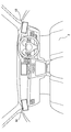
- FIG. 1 is a block diagram showing a configuration of a vehicle.
- FIG. 2 is a diagram illustrating an example of a display layout.
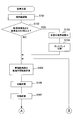
- FIG. 3 is a part of a flowchart of the parking support process.
- FIG. 4 is a part of a flowchart of the parking support process.
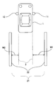
- FIG. 5 is a diagram showing a left-right bias calculation of the vehicle with respect to the parking frame
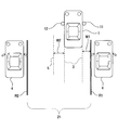
- FIG. 6 is a diagram illustrating a left / right deviation calculation of a vehicle with respect to another vehicle.
- FIG. 7 is a diagram showing a left / right deviation calculation of the vehicle with respect to the virtual line
- FIG. 1 is a block diagram showing a configuration of a vehicle.
- FIG. 2 is a diagram illustrating an example of a display layout.
- FIG. 3 is a part of a flowchart of the parking support process.
- FIG. 4 is a part of a flowchart of the parking support process.
- FIG. 5 is a diagram showing a left-
- FIG. 8 is a diagram showing the left / right deviation calculation when the vehicle is not parallel to the boundary line.
- FIG. 9 is a diagram showing an image for display display in a state where the vehicle is biased to the right
- FIG. 10 is a diagram illustrating a display display image in a state where the vehicle is biased to the left.
- FIG. 11 is a diagram showing a display display image in a state in which the vehicle is evenly accommodated on the left and right.
- FIG. 12 is a diagram showing a display display image in a state where the vehicle is tilted to the right.
- FIG. 13 is a diagram showing a display display image in a state where the vehicle is inclined leftward.
- FIG. 14A is a diagram illustrating a display example on the left display in a state where the vehicle is biased to the right with respect to the parking frame
- FIG. 14B is a diagram showing a display example on the right display in a state where the vehicle is biased to the right with respect to the parking frame
- FIG. 15 is a diagram showing a display example on the right display in a state where the vehicle is biased to the left with respect to the parking frame
- FIG. 16 is a diagram showing a display example on the right display in a state where the vehicle is evenly placed on the left and right with respect to the parking frame.
- FIG. 17 is a diagram showing a display example on the right display in a state where the vehicle is biased to the left with respect to the boundary line based on the other vehicle
- FIG. 18 is a diagram illustrating a display example on the right-side display in a state where the vehicle is equally left and right with respect to the boundary line based on the other vehicle.
- the vehicle 1 shown in FIG. 1 includes a right camera 11, a left camera 12, a right display 13, a left display 14, a control computer 15, a steering angle sensor 16, a shift position sensor 17, and a vehicle speed sensor 18.
- the right camera 11 is arranged in front of the right side of the vehicle 1 and images the right rear of the vehicle 1.
- the left camera 12 is disposed in front of the left side of the vehicle 1 and images the left rear of the vehicle 1.
- the front here means, for example, the front of the driver's seat.
- the right camera 11 is attached near the front of the door on the right front of the vehicle 1
- the left camera 12 is attached near the front of the door on the left front of the vehicle 1.
- attachment positions of the right camera 11 and the left camera 12 are merely examples, and are not limited thereto.
- the right camera 11 and the left camera 12 may be attached to left and right pillars, fenders, and the like.
- the right camera 11 and the left camera 12 of the present embodiment are wide angle cameras having an angle of view of about 180 degrees.
- the vicinity of the front door on the right front side of the vehicle 1 is usually an example of a position where the right side mirror is provided.
- the vicinity of the front side of the left front door of the vehicle 1 is typically an example of a position where the left side mirror is provided.
- the angle of view is also called a viewing angle.
- the right display 13 and the left display 14 are display devices that display an image for the driver to visually recognize.
- the right display 13 is disposed on the right side with respect to the driver in the driver's seat 20 in the vehicle 1, and the left display 14 is disposed on the left side with respect to the driver in the vehicle 1.
- the right display 13 is disposed on the right side of the instrument panel, and the left display 14 is disposed on the left side of the instrument panel.
- the instrument panel here is a general term for the equipment part in the front part of the passenger compartment in which meters, glove boxes, and the like are housed.
- the arrangement position of such a display is an example, and is not limited to this.
- the display may be arranged on each of the left and right pillars.
- the right display 13 displays an image acquired from the right camera 11, and the left display 14 displays an image acquired from the left camera 12. That is, the right display 13 and the left display 14 serve as so-called electronic side mirrors.
- the control computer 15 is a well-known electronic control device mainly composed of a microcomputer, controls each part of the vehicle 1 and executes a parking support process described later.
- this control computer 15 may be prepared for exclusive use of the parking assistance process, and may be a general-purpose computer that can execute processes other than the parking assistance process.
- the steering angle sensor 16 is a sensor that detects the steering angle of the steering of the vehicle 1, and outputs a signal corresponding to the actual steering angle based on the steering angle when traveling straight to the control computer 15.
- the shift position sensor 17 detects the shift position of the vehicle 1 and outputs the detection result to the control computer 15.
- the vehicle speed sensor 18 detects the vehicle speed and outputs a vehicle speed signal corresponding to the detected vehicle speed to the control computer 15.
- control computer 15 is a boundary line of the parking area 21 located behind the vehicle 1 where the driver intends to park from the captured images obtained by the right camera 11 and the left camera 12 by a known image processing technique.
- a boundary line representing a boundary in the vehicle width direction is recognized (S101).
- the boundary line refers to a parking frame 22 drawn in the parking lot in order to divide the parking lot, for example, as shown in FIG.
- the present invention is not limited to this.
- a boundary line based on the other vehicle 4 that is parked adjacent to the left and right across the parking area 21 where no parking frame is drawn is also recognized.
- the boundary line based on the other vehicle 4 is specified as a line that passes through a position corresponding to the vehicle width direction end of the other vehicle 4 and is parallel to the front-rear direction of the other vehicle 4.
- the parallel lines are shown as line R1 and line R2 in the example of FIG.
- the position corresponding to the vehicle width direction end here is the tip position of the side mirror of the other vehicle 4.
- the parking frame 22 and the lines R1 and R2 are recognized as boundary lines, but the boundary lines are not limited to these.
- the control computer 15 may recognize a boundary line based on an obstacle other than the other vehicle 4 such as a garage by a known image processing.
- the control computer 15 determines whether or not the length of the parking area 21 in the vehicle width direction (the distance between the two boundary lines) is more than twice the reference length. Is determined (S102).
- the reference length here is a general length in the vehicle width direction of an area for one vehicle that is divided by a parking frame in a parking lot or the like. That is, twice the reference length means that two common vehicles can be parked side by side.
- the parking frame 22 divides the parking lot at an interval of one vehicle, so the length of the parking area 21 in the vehicle width direction. Is determined to be less than twice the reference length (S102: NO).
- the parking area 21 in the vehicle width direction is also provided. Is determined to be less than twice the reference length (S102: NO).
- the length of the parking area 21 in the vehicle width direction Is determined to be at least twice the reference length (S102: YES).
- the control computer 15 calculates a virtual line 5 that divides the parking area 21. (S103), the process proceeds to S104.
- the virtual line 5 is a line that equally divides the length of the parking area 21 in the vehicle width direction (interval from the line R1 to the line R2) and is treated as a boundary line in the subsequent processing. Specifically, when the length of the parking area 21 in the vehicle width direction is N times or more and less than N + 1 times the reference length, N ⁇ 1 pieces of the length of the parking area 21 in the vehicle width direction are equally divided into N.
- a virtual line 5 is calculated (N is an integer of 2 or more). In the example illustrated in FIG. 7, the length of the parking area 21 in the vehicle width direction is two times or more and less than three times the reference length, and one virtual area that bisects the length of the parking area 21 in the vehicle width direction. Line 5 is calculated.
- the position of the vanishing point is specified in the images captured by the right camera 11 and the left camera 12.
- the position of the vanishing point is obtained, for example, by detecting the optical flow from the change in the captured image accompanying the movement of the vehicle 1.
- the present invention is not limited to this.
- the right camera 11 and the left camera 12 may be obtained from the installation positions and imaging directions.
- the three-dimensional shape of the other vehicle 4 in the captured image is estimated based on the position of the vanishing point.
- a position corresponding to the vehicle width direction end of the other vehicle 4 and a line parallel to the front-rear direction of the other vehicle 4 are specified.
- the position corresponding to the vehicle width direction end of the other vehicle 4 corresponds to the tip position of the side mirror.
- the lines parallel to the front-rear direction of the other vehicle 4 passing through the point corresponding to the end in the vehicle width direction down to the height of the ground are calculated as the above-described lines R1 and R2.
- N ⁇ 1 virtual lines 5 that divide line R1 and line R2 into N equal parts are calculated.
- the calculation method of such a virtual line 5 is an example, and is not limited to this.
- the three-dimensional shape of an obstacle such as the other vehicle 4 may be specified using a radar sensor, the line R1 and the line R2 may be calculated based on the specified three-dimensional shape, and the virtual line 5 may be calculated based on these. .
- the control computer 15 based on the three-dimensional shape of the other vehicle 4 described above, out of the other vehicles 4 parked adjacent to the left and right across the parking area 21, Determine which one is further away. Then, either the right display 13 or the left display 14 located on the side determined to be further away is switched to the wide range display mode (S104).
- the wide display mode here is a mode in which the wide-angle zoom of the right camera 11 and the left camera 12 to be switched to the wide display mode is performed at a predetermined ratio to display a wider range of captured images.
- the switching between the right camera 11 and the left camera 12 at a predetermined ratio is the wide-angle zoom, but the present invention is not limited to this.
- the other vehicle 4 may be zoomed at a ratio displayed in the image.
- the wide-angle zoom ratio may be changed according to the relative position of the other vehicle 4 with respect to the vehicle 1.
- one of the right display 13 and the left display 14 is switched to the wide range display mode.
- both the right display 13 and the left display 14 may be switched to the wide display mode.
- the right camera 11 and the left camera 12 are zoomed at a wide angle to display a wider range of captured images.
- the present invention is not limited to this. For example, by expanding the width of the right display 13 and the left display 14 (so-called wide display), the captured image may be displayed more widely.
- control computer 15 determines in S102 that the length of the parking area 21 in the vehicle width direction is not more than twice the reference length (S102: NO), the process proceeds to S105 without performing the process of S103. .
- control computer 15 detects the snake angle of the vehicle 1 by the steering angle sensor 16, and calculates the predicted trajectory 3 predicted from the snake angle as shown in FIG.
- the predicted trajectory 3 can be generated based on signals from the steering angle sensor 16 and the vehicle speed sensor 18 by using, for example, the Ackermann-Jantault method.
- the control computer 15 specifies the left and right intervals (interval W1 and interval W2) in the vehicle width direction between the predicted trajectory 3 and the boundary line (S106, S107).
- the method for specifying the interval is not particularly limited.
- the predicted trajectory 3 and the boundary line are combined in an image captured by the right camera 11 and the left camera 12, and the interval between the predicted trajectory 3 and the boundary line is specified in the image (for example, the number of pixels is counted). Good.
- the control computer 15 determines the left / right deviation of the vehicle 1 with respect to the boundary line (S108). Specifically, first, the difference between the value of the interval W1 specified in S106 and S107 and the value of the interval W2 is calculated. If the difference is outside the preset allowable range, if the value of the interval W1 is smaller than the value of the interval W2, it is determined that the value is biased to the right, and the interval W2 is greater than the interval W1. If the value is smaller than the value, it is determined that it is left biased. On the other hand, when the difference is within the allowable range, it is determined that the distance between the vehicle 1 and the boundary line is equal to the left and right.
- the allowable range is set to a range in which re-parking is not required due to the deviation of the vehicle 1 with respect to the boundary line (for example, the deviation is small), such as no inconvenience in getting on and off.
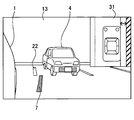
- the control computer 15 When it is determined that the image is right-biased (S108: right-bias), the control computer 15, for example, as shown in FIGS. 14A and 14B, shows a right-biased image 31 (FIG. 9) showing the result determined to be right-biased. ) Are displayed on the right display 13 and the left display 14 together with images taken from the right camera 11 and the left camera 12 (S109).
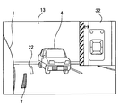
- the control computer 15 causes the right display 13 and the left display 14 to display a left-biased image 32 (FIG. 10) indicating the result determined to be left-biased. ) Are displayed together with images taken from the right camera 11 and the left camera 12 (S110).
- FIG. 15 is a display example of the right display 13 at that time.
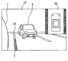
- the control computer 15 displays the equal image 33 indicating the result determined to be equal on the right display 13 and the left display 14.
- FIG. 11 is displayed together with images taken from the right camera 11 and the left camera 12 (S111).
- FIG. 16 shows a display example of the right display 13 at that time.
- the control computer 15 displays the right-biased image 31, the left-biased image 32 or the equivalent image 33 in the upper right portion of the image taken from the right camera 11 in the right display 13 and in the left camera 12 in the left display 14. Are displayed in an overlapping manner on the upper left part of the image taken from the above.
- the structure displayed on the upper right part of the right display 13 and the upper left part of the left display 14 was illustrated here, it is not limited to this, For example, you may display on the other position which does not overlap with the vehicle body of the vehicle 1. .
- the control computer 15 calculates a mark line 7 as a mark of the left and right deviation of the vehicle 1 with respect to the boundary line based on the boundary line and the predicted trajectory 3, and the calculated mark line 7 is
- the right display 13 displays the image captured from the right camera 11 and the left display 14 displays the image captured from the left camera 12.
- the mark line 7 is drawn as a solid line and is displayed as follows. First, as shown in FIGS. 14A and 14B, when it is determined that the vehicle 1 is biased to the right, the mark line 7 is displayed on the right side with respect to the parking frame 22 that is a boundary line. On the other hand, as shown in FIG. 15, for example, when it is determined that the vehicle 1 is biased to the left, the mark line 7 is displayed on the left side with respect to the parking frame 22 that is a boundary line. When it is determined that the vehicle 1 is equally biased and the boundary line is the parking frame 22, the mark line 7 is displayed on the same line as the center of the parking frame 22 in the vehicle width direction.
- the boundary line is the other vehicle 4
- the mark line 7 is drawn with a dotted line, and the following display is performed.
- the mark line 7 is on the left side with respect to the boundary lines (the lines R ⁇ b> 1 and R ⁇ b> 2 in FIG. 6) based on the other vehicle 4. Is displayed.
- the mark line 7 is displayed on the right side with respect to the boundary line based on the other vehicle 4.
- the mark line 7 is displayed on the same line as the boundary line based on the other vehicle 4.
- the boundary line based on the other vehicle 4 is not displayed.
- the present invention is not limited to this.
- the boundary line based on the other vehicle 4 may be displayed in addition to the mark line 7. Good.
- the control computer 15 may display the right-biased image 31, the left-biased image 32, or the uniform image 33 and the mark line 7 at the same time, or only one of them. May be.
- the mark line 7 is a solid line so that the driver can easily recognize which boundary line of the parking frame 22 and the other vehicle 4.
- the dotted line is used, but the present invention is not limited to this.
- the mark line 7 may be the same type of line in the parking frame 22 and the other vehicle 4.
- the lines L1, L2 and L3 in the images shown in FIGS. 9 to 11 all represent boundary lines and have different colors.
- the line L1 is displayed in red
- the line L2 is displayed in white
- the line L3 is displayed in green.
- the position of the vehicle icon 6 shown in each figure also varies depending on the biased situation of the vehicle 1. For example, as illustrated in FIG. 9, when it is determined that the vehicle 1 is biased to the right with respect to the boundary line, an image in which the vehicle icon 6 is biased to the right (line L1 side) is displayed. Also, as shown in FIG. 10, when it is determined that the vehicle 1 is biased to the left with respect to the boundary line, an image in which the vehicle icon 6 is biased to the left (line L1 side) is displayed.
- the arrow A in the images shown in FIGS. 9 and 10 is displayed between the line L ⁇ b> 1 and the vehicle icon 6 in order to emphasize the left / right bias of the vehicle 1 more.
- FIG. 11 when it is determined that the vehicle 1 is equal to the boundary line, an image in which the vehicle icon 6 is evenly positioned between the two lines L3 is displayed. With such a display mode, the driver who is parked backward can easily grasp the position of the vehicle 1 in the vehicle width direction with a glance at the image.
- the control computer 15 calculates the inclination of the vehicle 1 with respect to the boundary line (S113).
- the inclination of the vehicle 1 with respect to the boundary line can be determined by known image processing. For example, a method of calculating a center line that is equidistant from both of the recognized boundary lines and determining an angle formed by the center line and the center line of the vehicle 1 that has been grasped in advance may be used.
- the control computer 15 determines whether or not the magnitude of the inclination is greater than or equal to the reference angle (S114).
- the reference angle referred to here is an angle that becomes a boundary on whether the inclination of the vehicle 1 with respect to the boundary line may require re-parking such as inconvenience when getting on and off.
- control computer 15 determines whether the vehicle 1 is tilted to the left or right (S115).
- the control computer 15 displays the right tilt image 34 (FIG. 12) indicating the result determined to be right tilt as the right display 13 and the left display. 14 are displayed together with images taken from the right camera 11 and the left camera 12 (S116).
- the control computer 15 displays the left tilt image 35 (FIG. 13) indicating the result determined to be left tilt as the right display 13 and Each of the left displays 14 is displayed together with images taken from the right camera 11 and the left camera 12 (S117).
- control computer 15 displays the equal image 33 (FIG. 11) indicating the result of determination as parallel to the right display 13 and the left side.
- Each of the displays 14 is displayed together with images taken from the right camera 11 and the left camera 12 (S118).
- the line L4 in the images shown in FIGS. 12 and 13 means a boundary line as in the above-described L1 to L3.
- the line L4 is displayed in yellow.
- a right tilt image 34 in which the vehicle icon 6 is tilted to the right (line L4 side) is displayed.
- a left tilt image 35 in which the vehicle icon 6 is tilted to the left (line L4 side) is displayed.
- the driver can easily grasp the inclination of the vehicle 1 with respect to the boundary line at the end of parking, just by looking at the image.
- control computer 15 determines whether or not the engine of the vehicle 1 is off (S119). When it determines with an engine being off (S119: YES), the parking assistance process of this embodiment is complete
- control computer 15 determines whether or not a preset reference time has elapsed since the shift lever position was changed to D (drive) by the driver's operation, and the vehicle speed is equal to or higher than the preset reference speed. Determine whether. That is, it is determined whether or not the vehicle has shifted to normal traveling.
- the control computer 15 When it is determined that the reference time has not elapsed since the shift lever position was changed to D, or when it is determined that the vehicle speed is less than the reference speed (S120: NO), the control computer 15 performs processing. To S105. On the other hand, when it is determined that the reference time has elapsed since the shift lever position is changed to D and the vehicle speed is equal to or higher than the reference speed (S120: YES), the control computer 15 ends the parking assistance process.
- the control computer 15 displays a right-biased image 31, a left-biased image 32, or an equivalent image 33 indicating the left-right bias of the vehicle 1 together with the captured images on the right display 13 and the left display 14 that function as so-called electronic side mirrors. Therefore, according to the present embodiment, the driver can grasp the left-right bias of the vehicle 1 only by confirming one of the right display 13 and the left display 14, and can easily perform the driving operation during reverse parking. . That is, for example, in order to grasp the left-right bias of the vehicle 1 with a normal side mirror during reverse parking, the left and right side mirrors must be checked alternately.
- each of the right display 13 and the left display 14 displays an image corresponding to the side mirror and an image showing the left-right bias (the same image), so only one display is confirmed.
- the left / right bias of the vehicle 1 can be grasped.
- the control computer 15 recognizes the parking frame 22 that divides the parking lot as a boundary line. Therefore, according to this embodiment, a parking assistance process can be performed in the parking lot where the parking frame 22 is drawn.
- the control computer 15 draws lines (line R1 and line R2) parallel to the front-rear direction of the other vehicle 4 passing through a position corresponding to the vehicle width direction end of the side surface of the other vehicle 4 parked adjacent to the parking area 21. Recognize as a boundary line. Therefore, according to the present embodiment, the parking support process can be performed even in a place where the parking frame 22 does not exist.
- the control computer 15 calculates a virtual line 5 that divides the parking area 21 in the vehicle width direction, and sets the virtual line 5 as a boundary. Recognize as a line. Therefore, when the vehicle 1 parks backward, even if there are two or more spaces in the parking area 21, it is possible to perform appropriate parking assistance processing by calculating the virtual line 5 that divides the parking area 21.
- the control computer 15 When the length of the parking area 21 in the vehicle width direction is twice or more the reference length, the control computer 15 is located on the side of either the left or right other vehicle 4 that is further away from the vehicle 1. The right display 13 and the left display 14 are switched to the wide display mode. Therefore, when the vehicle 1 parks backward, even if there are two or more spaces in the parking area 21, the driver can more appropriately grasp the parking area 21 and the other vehicle 4.
- the control computer 15 detects the steering angle of the vehicle 1 by the steering angle sensor 16, and calculates the expected trajectory 3 according to the snake angle. Therefore, the control computer 15 can grasp the backward direction of the vehicle 1.
- the control computer 15 recognizes the boundary line, specifies the left and right intervals in the vehicle width direction between the predicted trajectory 3 and the boundary line, and determines left and right bias. Further, a right-biased image 31, a left-biased image 32, or an equivalent image 33 indicating the determined result is displayed on the right display 13 and the left display 14 together with images taken from the right camera 11 and the left camera 12. Therefore, it is possible to perform a parking assist process that predicts the backward direction of the vehicle.
- the control computer 15 calculates a mark line 7 that serves as a mark for the left and right deviation of the vehicle 1 with respect to the boundary line, and displays the calculated mark line 7 on the right display 13 and the left side.
- Each of the displays 14 is displayed together with a right-biased image 31, a left-biased image 32, or a uniform image 33. Therefore, when checking the display, the driver can grasp not only the right-biased image 31, the left-biased image 32, or the uniform image 33 but also the left-right bias of the vehicle 1 not only by the mark line 7.
- the control computer 15 determines the inclination of the vehicle 1 with respect to the boundary line, and displays the right inclination image 34, the left inclination image 35 or the equal image 33 indicating the determined result on the right display 13 and the left display 14, respectively. And displayed together with images taken from the right camera 11 and the left camera 12. Therefore, the driver can easily grasp the inclination of the vehicle 1 at the end of parking.
- the control computer 15 displays a right-biased image 31, a left-biased image 32, a uniform image 33, a right-tilted image 34, and a left-tilted image 35 on the right side (outside) of the right display 13 and the left side (outside) of the left display 14, respectively. To do. Therefore, in each of the right display 13 and the left display 14, the right-biased image 31, the left-biased image 32, and the like can be displayed at positions where the vehicle 1 of the vehicle 1 is difficult to overlap.
- control computer 15 corresponds to an example of a parking assistance device
- S101 to S108, S112 to S115 correspond to an example of processing as a calculation unit
- S109 to S111, S116 to S118 are display processing units.
- the calculation unit is also called a calculation processing unit.
- S102 corresponds to an example of processing as a length determination unit
- S103 corresponds to an example of processing as a first calculation unit
- S105 corresponds to an example of processing as a second calculation unit
- S106 to S108 Corresponds to an example of processing as a bias determination unit.
- the right bias image 31, the left bias image 32, the uniform image 33, and the mark line 7 correspond to an example of a vehicle bias image
- the uniform image 33, the right tilt image 34, and the left tilt image 35 correspond to an example of a vehicle tilt image.
- the length determination unit is also called a first determination unit
- the bias determination unit is also called a second determination unit.
- the form of the right display 13 and the left display 14 in the above embodiment is not particularly limited.
- a liquid crystal display, an organic EL display, a plasma display, or the like may be used, and an image may be displayed over a landscape that can be seen through a transparent member.
- the reference length is a general length for one vehicle in the vehicle width direction divided by a parking lot or the like, but is not limited to this.
- the driver may directly input the reference length to the control computer 15.
- the position corresponding to is the tip position of the side mirror of the other vehicle 4, but is not limited to this.
- the vehicle body side surface of the other vehicle 4 may be a position corresponding to the vehicle width direction end.
- the allowable range of the difference between the interval W1 and the interval W2 is set in advance, but the present invention is not limited to this.
- the driver may directly input the allowable range to the control computer 15.
- the present invention is not limited to this.
- the image is not displayed, and only when the vehicle 1 is determined to be biased to the right or left, the right-biased image 31 or It may be configured to display the left biased image 32.
- the mark line 7 may be displayed in addition to the right-biased image 31 or the left-biased image 32 as in the above embodiment.
- the mark line 7 may be displayed instead of the right biased image 31 or the left biased image 32.
- the configuration in which any one of the right-biased image 31, the left-biased image 32, and the equivalent image 33 shown in FIGS. 9 to 11 is displayed on the right display 13 and the left display 14 is illustrated. It is not something. For example, not only the right-biased image 31, the left-biased image 32, or the uniform image 33, but an image that matches the reverse state of the vehicle 1 may be displayed. For example, when the vehicle 1 is not located between the boundary lines, such as when reverse parking starts, the vehicle icon 6 displayed in FIGS. 9 to 11 is higher than between the line L1, the line L2, or the line L3. You may make it display the image arrange
- the vehicle icon 6 displays an image arranged between the line L1, the line L2, or the line L3. It may be. Also, for example, when the vehicle 1 is biased to the right with respect to the boundary line, an image in which the vehicle icon 6 is arranged to the right is displayed, and when the vehicle 1 is biased to the left with respect to the boundary line, the vehicle icon 6 is An image arranged on the left side may be displayed.
- the line L1, the line L2, and the line L3 have different colors, but the present invention is not limited to this.
- all the colors may be unified, the line L1 and the line L2 may be the same color, and the line L3 may be divided as a different color.
- the present invention is not limited to this.
- the arrow A may not be displayed.
- the present invention is not limited to this.
- the mark line 7 may not be displayed, the expected trajectory 3 may be displayed instead of the mark line 7, or both may be displayed.
- the configuration for determining whether or not the magnitude of the inclination of the vehicle 1 is equal to or larger than the reference angle is exemplified, but the present invention is not limited to this.
- the driver may directly input the reference angle to the control computer 15.
- the line L4 displayed in the right tilt image 34 and the left tilt image 35 of the vehicle 1 is a single color, but the present invention is not limited to this.
- the line L4 may have different colors for the right tilt image 34 and the left tilt image 35.
- the configuration in which the equal image 33, the right tilt image 34, or the left tilt image 35 indicating the result of determining the tilt of the vehicle 1 is displayed on the right display 13 and the left display 14 is illustrated, but the present invention is not limited thereto. It is not something.
- the right bias image 31, the left bias image 32, or the uniform image 33 indicating the determined result may be displayed together with the tilt image while the tilt is determined at the same time.
- a preset reference time it is determined whether or not a preset reference time has elapsed since the shift lever position is changed to D (drive) by a driver operation, and the vehicle speed is equal to or higher than a preset reference speed.
- the present invention is not limited to this.
- the driver may directly input one or both of the reference time and the reference speed to the control computer 15.
- the right display 13 and the left display 14 serve as so-called electronic side mirrors, but are not limited thereto.
- the vehicle 1 may be configured to provide a general side mirror together with the right display 13 and the left display 14 (electronic side mirror).
- one component in the above embodiment may be distributed as a plurality of components, or the functions of a plurality of components may be integrated into one component. Moreover, you may abbreviate
- at least a part of the configuration of the above embodiment may be added to or replaced with the configuration of the other embodiment.
- the present disclosure can be realized in various forms such as a program executed by the control computer 15 described above, a medium storing the program, a vehicle control method, and the like.
- each step is expressed as, for example, S101. Further, each step can be divided into a plurality of sub-steps, while a plurality of steps can be combined into one step.
Landscapes
- Engineering & Computer Science (AREA)
- Mechanical Engineering (AREA)
- Multimedia (AREA)
- Chemical & Material Sciences (AREA)
- Combustion & Propulsion (AREA)
- Transportation (AREA)
- Signal Processing (AREA)
- Physics & Mathematics (AREA)
- General Physics & Mathematics (AREA)
- Theoretical Computer Science (AREA)
- Closed-Circuit Television Systems (AREA)
- Traffic Control Systems (AREA)
- Image Analysis (AREA)
Abstract
駐車支援装置は、車両(1)に搭載され、車両の右側後方を撮像するカメラによって得られた撮像画像を、右側ディスプレイに表示し、車両の左側後方を撮像するカメラによって得られた撮像画像を、左側ディスプレイ(14)に表示する、表示処理部と、駐車領域(21)の境界線を認識し、車両と境界線との間隔を特定して左右の偏りを判定する計算部と、を備える。表示処理部は、計算部によって判定された結果を示す車両偏り画像(31)を、右側ディスプレイと左側ディスプレイそれぞれに撮像画像とともに表示する。
Description
本出願は、2014年10月29日に出願された日本国特許出願2014-220326号に基づくものであり、その開示をここに参照により援用する。
本開示は、車両用の駐車支援装置に関する。
車両の後退駐車を支援する技術として、車両リア部に設けられたカメラによる撮像画像を車室内のディスプレイに表示する技術(いわゆるバックモニター)や、車両の前後左右に設けられたカメラによる撮像画像を合成して得られた鳥瞰図を車室内のディスプレイに表示する技術(いわゆるトップビューモニター)が知られている。また、車両の後方を撮像する車両左右に設けられたカメラによる撮像画像(サイドミラー相当の画像)を、車室内のディスプレイに表示されている鳥瞰図の左右に追加表示させる駐車支援装置が提案されている(特許文献1参照)。
本願発明者は車両用の駐車支援装置に関して下記を見出した。
バックモニターでは、車両を後退駐車する際、駐車枠内に車両が進入していくと、駐車枠がカメラの視野から外れ、ドライバーは駐車枠と車両との位置関係をバックモニターから視認できなくなるおそれがある。トップビューモニターは、車両が駐車枠へ進入後も車両と駐車枠との位置関係を把握することができるが、実際に車両の真上から撮像された画像ではなく、撮像された画像に変換処理を施し合成した画像であるため、視認できない死角が発生し得る。つまり、バックモニターや鳥瞰図だけでは車両後方の状況を視認するには十分ではないおそれがある。
例えば前述した特許文献1に記載の構成では、鳥瞰図だけでなくサイドミラー相当の画像も確認する必要がある。ただし、サイドミラー相当の画像はディスプレイにおいて左右に分かれて表示されているため、駐車枠の間に車両が均等に入るようにするには、ディスプレイに表示された左右の画像を交互に何度も確認しなければならないおそれがある。なお、この問題は通常のサイドミラーにも生じ得る。
特に運転初心者など後退駐車に慣れていない運転者は、サイドミラー相当の画像又はサイドミラーをそれぞれ注視しながら1度で左右均等に駐車するのは困難な場合が多く、駐車し直さなければならないおそれがある。
本開示は、サイドミラー相当の左右の画像を交互に確認する手間を抑制しつつ、駐車枠内に左右均等に車両を駐車しやすくする駐車支援技術の提供を目的としている。
本開示の一例に係る、車両に搭載された駐車支援装置は、表示処理部と、計算部と、を備える。表示処理部は、車両の右側前方に設置され、車両の右側後方を撮像するカメラによって得られた撮像画像を、車両の室内のドライバーに対して右側に配置された右側ディスプレイに表示し、車両の左側前方に設置され、車両の左側後方を撮像するカメラによって得られた撮像画像を、車両の室内のドライバーに対して左側に配置された左側ディスプレイに表示する。計算部は、車両の後方にある駐車領域の境界線を認識し、車両と境界線との車幅方向における間隔を左右それぞれ特定して左右の偏りを判定する。そして、表示処理部は、計算部によって判定された結果を示す車両偏り画像を、右側ディスプレイと左側ディスプレイそれぞれにカメラの撮像画像とともに表示する。
このような構成によれば、サイドミラー相当の画像を表示する左右のディスプレイのうち、一方のディスプレイを確認するだけで車両の左右の偏りを把握することができる。したがって、後退駐車中の運転操作が容易となる。
本開示についての上記および他の目的、特徴や利点は、添付の図面を参照した下記の詳細な説明から、より明確になる。添付図面において、
図1は、車両の構成を示すブロック図であり、
図2は、ディスプレイ配置レイアウトの一例を示す図であり、
図3は、駐車支援処理のフローチャートの一部であり、
図4は、駐車支援処理のフローチャートの一部であり、
図5は、駐車枠に対する車両の左右の偏り算出を示す図であり、
図6は、他車両に対する車両の左右の偏り算出を示す図であり、
図7は、仮想線に対する車両の左右の偏り算出を示す図であり、
図8は、境界線に対し車両が平行でない場合の左右の偏り算出を示す図であり、
図9は、車両が右に偏っている状態のディスプレイ表示用画像を示す図であり、
図10は、車両が左に偏っている状態のディスプレイ表示用画像を示す図であり、
図11は、車両が左右均等に収まっている状態のディスプレイ表示用画像を示す図であり、
図12は、車両が右斜めに傾いている状態のディスプレイ表示用画像を示す図であり、
図13は、車両が左斜めに傾いている状態のディスプレイ表示用画像を示す図であり、
図14Aは、駐車枠に対し車両が右に偏っている状態の左側ディスプレイにおける表示例を示す図であり、
図14Bは、駐車枠に対し車両が右に偏っている状態の右側ディスプレイにおける表示例を示す図であり、
図15は、駐車枠に対し車両が左に偏っている状態の右側ディスプレイにおける表示例を示す図であり、
図16は、駐車枠に対し車両が左右均等に収まっている状態の右側ディスプレイにおける表示例を示す図であり、
図17は、他車両に基づく境界線に対し車両が左に偏っている状態の右側ディスプレイにおける表示例を示す図であり、
図18は、他車両に基づく境界線に対し車両が左右均等に収まっている状態の右側ディスプレイにおける表示例を示す図である。
以下、本開示の例示的な実施形態について図面を参照しながら説明する。
(1.構成)
図1に示す車両1は、右側カメラ11、左側カメラ12、右側ディスプレイ13、左側ディスプレイ14、制御コンピュータ15、操舵角センサ16、シフトポジションセンサ17及び車速センサ18を備える。
図1に示す車両1は、右側カメラ11、左側カメラ12、右側ディスプレイ13、左側ディスプレイ14、制御コンピュータ15、操舵角センサ16、シフトポジションセンサ17及び車速センサ18を備える。
右側カメラ11は、車両1の右側前方に配置され、車両1の右側後方を撮像する。同様に、左側カメラ12は、車両1の左側前方に配置され、車両1の左側後方を撮像する。ここでいう前方とは、例えば運転席よりも前方を意味する。具体的には、図5等に示すように、右側カメラ11は車両1の右側前方のドア前方付近に、左側カメラ12は車両1の左側前方のドア前方付近に取り付けられている。ただし、このような右側カメラ11及び左側カメラ12の取付位置は一例であり、これに限定されず、例えば、左右それぞれのピラーやフェンダーなどに取り付けられてもよい。また、本実施形態の右側カメラ11及び左側カメラ12は、約180度の画角を持つ広角カメラである。車両1の右側前方のドア前方付近は、通常、右側のサイドミラーが設けられる位置の一例である。車両1の左側前方のドア前方付近は、通常、左側のサイドミラーが設けられる位置の一例である。画角は視野角とも呼ぶ。
図2に示すように、右側ディスプレイ13及び左側ディスプレイ14は、ドライバーが視認するための画像を表示する表示装置である。右側ディスプレイ13は、車両1の室内の運転席20にいるドライバーに対して右側に配置され、左側ディスプレイ14は、車両1の室内のドライバーに対して左側に配置されている。本実施形態では、右側ディスプレイ13は、インストルメントパネルの右側に配置され、左側ディスプレイ14は、インストルメントパネルの左側に配置されている。ここでいうインストルメントパネルは、メータ類やグローブボックス等が収まっている車室前部の装備部分の総称を意味する。ただし、このようなディスプレイの配置位置は一例であり、これに限定されず、例えば左右それぞれのピラーに配置されてもよい。右側ディスプレイ13は、右側カメラ11から取得した画像を、左側ディスプレイ14は、左側カメラ12から取得した画像を表示する。つまり、右側ディスプレイ13及び左側ディスプレイ14は、いわゆる電子サイドミラーの役割を果たす。
制御コンピュータ15は、マイクロコンピュータを中心に構成された周知の電子制御装置であり、車両1の各部を制御し、後述する駐車支援処理を実行する。なお、この制御コンピュータ15は、駐車支援処理専用に用意されたものであってもよく、また、駐車支援処理以外の処理についても実行可能な汎用のコンピュータであってもよい。
操舵角センサ16は、車両1のステアリングの操舵角を検出するセンサであり、直進時の操舵角を基準とした実際の操舵角に応じた信号を制御コンピュータ15に出力する。
シフトポジションセンサ17は、車両1のシフトポジションを検出し、検出結果を制御コンピュータ15に出力する。
車速センサ18は、車速を検出し、検出された車速に応じた車速信号を制御コンピュータ15に出力する。
(2.駐車支援処理の概要)
次に、本実施形態の制御コンピュータ15により実現される駐車支援処理の概要について、図3及び図4のフローチャートを用いて説明する。この駐車支援処理は、ドライバーの操作によってシフトレバー位置がR(リバース)に変更され、シフトポジションセンサ17による検出情報が制御コンピュータ15に入力されることにより開始される。なお、制御コンピュータ15は、駐車支援処理の開始前後にかかわらず、右側カメラ11によって得られた撮像画像を右側ディスプレイ13に、左側カメラ12によって得られた撮像画像を左側ディスプレイ14に、常に表示する。
次に、本実施形態の制御コンピュータ15により実現される駐車支援処理の概要について、図3及び図4のフローチャートを用いて説明する。この駐車支援処理は、ドライバーの操作によってシフトレバー位置がR(リバース)に変更され、シフトポジションセンサ17による検出情報が制御コンピュータ15に入力されることにより開始される。なお、制御コンピュータ15は、駐車支援処理の開始前後にかかわらず、右側カメラ11によって得られた撮像画像を右側ディスプレイ13に、左側カメラ12によって得られた撮像画像を左側ディスプレイ14に、常に表示する。
まず、制御コンピュータ15は、右側カメラ11及び左側カメラ12によって得られた撮像画像から、周知の画像処理技術によって、ドライバーが駐車しようとする車両1の後方にある駐車領域21の境界線であって車幅方向の境界を表す境界線を認識する(S101)。
ここでいう境界線とは、例えば図5に示すように、駐車場を区分するために駐車場に描かれている駐車枠22である。ただし、これに限らず、例えば図6に示すように、駐車枠の描かれていない駐車領域21を挟んで左右に隣接して駐車された他車両4に基づく境界線も認識する。他車両4に基づく境界線は、当該他車両4の車幅方向末端に相当する位置を通過する、当該他車両4の前後方向に平行な線として特定される。平行な線は、図6の例では線R1及び線R2として示される。ここでいう車幅方向末端に相当する位置とは、本実施形態では、他車両4のサイドミラーの先端位置とする。また、線R1及び線R2の具体的な算出方法については後述する。なお、本実施形態では駐車枠22及び線R1、線R2を境界線として認識するようにしているが、境界線はこれらに限定されない。例えば、制御コンピュータ15は、車庫などのような他車両4以外の障害物に基づく境界線についても周知の画像処理によって認識してもよい。
次に、制御コンピュータ15は、S101で認識した境界線に基づいて、車幅方向における駐車領域21の長さ(2つの境界線間の距離)が基準長さの2倍以上であるか否かを判定する(S102)。ここでいう基準長さとは、駐車場などで駐車枠により区分される車両1台分の領域の車幅方向における一般的な長さである。つまり基準長さの2倍とは、一般的な車両が2台並んで駐車できることを意味する。
例えば図5に示すように、認識した境界線が駐車枠22である場合、駐車枠22は駐車場を車両1台分ずつの間隔で区分しているので、車幅方向における駐車領域21の長さが基準長さの2倍未満であると判定される(S102:NO)。
また、例えば図6に示すように、認識した境界線が線R1及び線R2であって線R1から線R2までの間隔が車両2台分未満である場合にも、車幅方向における駐車領域21の長さが基準長さの2倍未満であると判定される(S102:NO)。
一方、例えば図7に示すように、認識した境界線が線R1及び線R2であって線R1から線R2までの間隔が車両2台分以上である場合、車幅方向における駐車領域21の長さが基準長さの2倍以上であると判定される(S102:YES)。
S102で、制御コンピュータ15は、車幅方向における駐車領域21の長さが基準長さの2倍以上であると判定した場合(S102:YES)、駐車領域21を区分する仮想線5を算出して(S103)、S104へ移行する。仮想線5は、車幅方向における駐車領域21の長さ(線R1から線R2までの間隔)を複数等分する線であり、以降の処理において境界線として扱われる。具体的には、車幅方向における駐車領域21の長さが基準長さのN倍以上N+1倍未満である場合、車幅方向における駐車領域21の長さをN等分するN-1本の仮想線5が算出される(Nは2以上の整数)。図7に示す例では、車幅方向における駐車領域21の長さが基準長さの2倍以上3倍未満であり、車幅方向における駐車領域21の長さを2等分する1本の仮想線5が算出される。
ここで、仮想線5の算出方法の一例について説明する。まず、右側カメラ11及び左側カメラ12による撮像画像において、消失点の位置が特定される。消失点の位置は、例えば、車両1の動きに伴う撮像画像の変化からオプティカルフローを検出することによって求められる。ただし、これに限定されず、例えば、右側カメラ11及び左側カメラ12の設置位置や撮像方向などから求められるようにしてもよい。次に、消失点の位置に基づいて、撮像画像における他車両4の立体形状が推測される。こうして推測された他車両4の立体形状に基づき、当該他車両4の車幅方向末端に相当する位置と、当該他車両4の前後方向に平行な線と、が特定される。当該他車両4の車幅方向末端に相当する位置は、本実施形態ではサイドミラーの先端位置に相当する。そして、車幅方向末端に相当する位置を地面の高さまで下ろした点を通り、他車両4の前後方向に平行な線が、前述した線R1及び線R2として算出される。その後、線R1及び線R2をN等分するN-1本の仮想線5が算出される。なお、このような仮想線5の算出方法は一例であり、これに限定されない。例えば、レーダーセンサ等を用いて他車両4等の障害物の立体形状を特定し、特定した立体形状に基づき線R1及び線R2を算出し、これらに基づいて仮想線5を算出してもよい。
次に、制御コンピュータ15は、図17に示すように、前述した他車両4の立体形状に基づき、駐車領域21を挟んで左右に隣接して駐車された他車両4のうち、車両1との距離がより離れている方を判定する。そして、より離れていると判定された方の側に位置する、右側ディスプレイ13又は左側ディスプレイ14のいずれか一方を、広範囲表示モードに切り替える(S104)。ここでいう広範囲表示モードは、右側カメラ11及び左側カメラ12のうち広範囲表示モードに切り替える方を所定の比率で広角ズームし、撮像される画像の範囲をより広く表示するモードである。なお、本実施形態では、所定の比率で右側カメラ11及び左側カメラ12のうち切り替える方を広角ズームするとしたが、これに限定されない。例えば、他車両4が画像に表示される比率でズームするようにしてもよい。換言すれば、車両1に対する他車両4の相対位置に応じて広角ズームの比率を変更してもよい。また、本実施形態では、右側ディスプレイ13又は左側ディスプレイ14のいずれか一方を広範囲表示モードに切り替えるとしたが、これに限定されない。例えば、右側ディスプレイ13及び左側ディスプレイ14の両方を広範囲表示モードに切り替えてもよい。また、本実施形態では、右側カメラ11及び左側カメラ12を広角ズームすることにより、撮像される画像の範囲をより広く表示するとしたが、これに限定されない。例えば、右側ディスプレイ13及び左側ディスプレイ14の幅を拡張することにより(いわゆるワイド表示)、撮像される画像をより広く表示させてもよい。
一方、S102で、制御コンピュータ15は、車幅方向における駐車領域21の長さが基準長さの2倍以上でないと判定した場合(S102:NO)、S103の処理を行わずにS105へ移行する。
S105で、制御コンピュータ15は、操舵角センサ16により車両1の蛇角を検出して、図8に示すように、当該蛇角から予想した予想軌跡3を計算する。予想軌跡3については、例えば、アッカ―マン・ジャントー式等を用いれば、操舵角センサ16及び車速センサ18からの信号に基づいて生成することができる。
次に、制御コンピュータ15は、予想軌跡3と境界線との車幅方向における間隔(間隔W1及び間隔W2)を、左右それぞれ特定する(S106、S107)。間隔の特定方法は特に限定されない。例えば、予想軌跡3及び境界線を右側カメラ11及び左側カメラ12によって撮像された画像中に合成し、当該画像において予想軌跡3と境界線との間隔を特定(例えばピクセル数をカウント)してもよい。
次に、制御コンピュータ15は、境界線に対する車両1の左右の偏りを判定する(S108)。具体的には、まずS106及びS107で特定した間隔W1の値と間隔W2の値との差分を計算する。そして、当該差分があらかじめ設定されている許容範囲外である場合には、間隔W1の値の方が間隔W2の値よりも小さければ右偏りであると判定し、間隔W2の方が間隔W1の値よりも小さければ左偏りであると判定する。一方、当該差分が許容範囲内の場合には、境界線に対する車両1の間隔は左右均等であると判定する。ここでいう許容範囲とは、例えば、乗降車の際不都合が生じることがないなど、境界線に対する車両1の偏りによって駐車のやり直しが必要とならない範囲(偏りが小さい範囲)に設定されている。
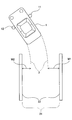
右偏りであると判定された場合(S108:右偏り)、制御コンピュータ15は、例えば図14A及び図14Bに示すように、右偏りであると判定された結果を示す右偏り画像31(図9)を、右側ディスプレイ13及び左側ディスプレイ14に、右側カメラ11及び左側カメラ12から撮像した画像とともに表示する(S109)。
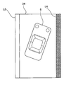
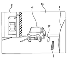
また、左偏りであると判定された場合(S108:左偏り)、制御コンピュータ15は、右側ディスプレイ13及び左側ディスプレイ14に、左偏りであると判定された結果を示す左偏り画像32(図10)を、右側カメラ11及び左側カメラ12から撮像した画像とともに表示する(S110)。図15はその際の右側ディスプレイ13の表示例である。
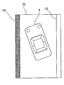
一方、間隔W1と間隔W2とが均等であると判定された場合(S108:均等)、制御コンピュータ15は、右側ディスプレイ13及び左側ディスプレイ14に、均等であると判定された結果を示す均等画像33(図11)を、右側カメラ11及び左側カメラ12から撮像した画像とともに表示する(S111)。図16はその際の右側ディスプレイ13の表示例である。
S109~S111において、制御コンピュータ15は、右偏り画像31、左偏り画像32又は均等画像33を、右側ディスプレイ13には右側カメラ11から撮像した画像における右上部に、左側ディスプレイ14には左側カメラ12から撮像した画像における左上部に、重ねて表示する。なお、ここでは、右側ディスプレイ13の右上部及び左側ディスプレイ14の左上部に表示する構成を例示したが、これに限定せず、例えば車両1の車体に重ならない他の位置に表示してもよい。
また、S109~S111において、制御コンピュータ15は、境界線と予想軌跡3とに基づいて、境界線に対する車両1の左右の偏りの目印となる目印線7を算出し、算出した目印線7を、右側ディスプレイ13には右側カメラ11から撮像した画像に重ねて、左側ディスプレイ14には左側カメラ12から撮像した画像に重ねて表示する。
本実施形態では、境界線が駐車枠22である場合、目印線7は実線で描かれ、次のように表示される。まず、図14A及び図14Bに示すように、車両1が右に偏っていると判定された場合、目印線7は境界線である駐車枠22に対して右側に表示される。一方、例えば図15に示すように、車両1が左に偏っていると判定された場合、目印線7は境界線である駐車枠22に対して左側に表示される。車両1の偏りが均等であると判定され、境界線が駐車枠22の場合、目印線7は車幅方向における駐車枠22の中心と同一線上に表示される。
一方、境界線が他車両4である場合、目印線7は点線で描かれ、以下の表示を行う。まず、図17に示すように、車両1が左に偏っていると判定された場合、目印線7は、他車両4に基づく境界線(図6でいう線R1及び線R2)に対し左側に表示される。車両1が右に偏っていると判定された場合には、目印線7は、他車両4に基づく境界線に対し右側に表示される。車両1の偏りが均等であると判定された場合、目印線7は他車両4に基づく境界線と同一線上に表示される。なお、本実施形態では、他車両4に基づく境界線が表示されないとしたが、これに限定されず、例えば、目印線7に加えて他車両4に基づく境界線も表示されるようにしてもよい。
また、図14A~図16に示すように、制御コンピュータ15は、右偏り画像31、左偏り画像32又は均等画像33と目印線7とを同時に表示してもよいし、いずれか一方のみを表示してもよい。また、本実施形態では、ドライバーが駐車枠22及び他車両4のうちいずれの境界線であるか、より認識しやすいように、境界線が駐車枠2である場合は目印線7を実線とし、他車両4である場合においては点線としたが、これに限定されるものではない。例えば、目印線7を駐車枠22及び他車両4で同一の種類の線としてもよい。
ここで、図9~図11に示す画像中の線L1、線L2及び線L3はすべて境界線を意味し、それぞれ異なる色である。例えば、線L1は赤色、線L2は白色、線L3は緑色で表示される。また、それぞれの図中に示されている車両アイコン6の位置も、車両1の偏り状況によって異なる。例えば図9に示すように、境界線に対し車両1が右に偏っていると判定された場合は、車両アイコン6が右(線L1側)に偏っている画像が表示される。また、図10に示すように、境界線に対し車両1が左に偏っていると判定された場合は、車両アイコン6が左(線L1側)に偏っている画像が表示される。ここで、図9及び図10に示す画像中の矢印Aは、車両1の左右の偏りをより強調させるために、線L1と車両アイコン6との間に表示される。また、図11に示すように、境界線に対し車両1が均等であると判定された場合は、車両アイコン6が2本の線L3の間に均等に位置する画像が表示される。このような表示態様により、後退駐車中のドライバーは、画像を一目見ただけで、車幅方向における車両1の位置を容易に把握することができる。
図4に戻り、制御コンピュータ15は、車速センサ18による車速=0km/hの検出情報及びシフトポジションセンサ17によるシフトレバー位置=P(パーキング)の検出情報のうち少なくとも一方が入力されたか否かを判定する(S112)。
少なくとも一方の検出情報が入力されたと判定した場合(S112:YES)、制御コンピュータ15は、境界線に対する車両1の傾きを計算する(S113)。境界線に対する車両1の傾きは、周知の画像処理によって判定可能である。例えば、認識された境界線の双方から等距離にある中心線を算出し、当該中心線と、あらかじめ把握されている車両1の中心線とがなす角度を判定する方法を用いてもよい。
次に、制御コンピュータ15は、傾きの大きさが基準の角度以上であるか否かを判定する(S114)。ここでいう基準の角度とは、例えば境界線に対する車両1の傾きが、乗降車の際不都合が生じるなど、駐車のやり直しが必要となるかならないかの境界となる角度である。
傾きの大きさが基準の角度以上であると判定した場合(S114:YES)、制御コンピュータ15は、車両1が左右いずれかに傾いているかを判定する(S115)。
車両1が右側に傾いていると判定した場合(S115:右傾き)、制御コンピュータ15は、右傾きであると判定した結果を示す右傾き画像34(図12)を、右側ディスプレイ13及び左側ディスプレイ14それぞれに、右側カメラ11及び左側カメラ12から撮像した画像とともに表示する(S116)。
一方、車両1が左側に傾いていると判定した場合(S115:左傾き)、制御コンピュータ15は、左傾きであると判定した結果を示す左傾き画像35(図13)を、右側ディスプレイ13及び左側ディスプレイ14それぞれに、右側カメラ11及び左側カメラ12から撮像した画像とともに表示する(S117)。
一方、判定した傾きが基準の角度未満であると判定した場合(S114:NO)、制御コンピュータ15は、平行であると判定した結果を示す均等画像33(図11)を、右側ディスプレイ13及び左側ディスプレイ14それぞれに、右側カメラ11及び左側カメラ12から撮像した画像とともに表示する(S118)。
図12及び図13に示す画像中の線L4は、前述したL1~L3と同様、境界線を意味する。例えば、線L4は黄色で表示される。図12に示すように、境界線に対し車両1が右に傾いていると判定された場合は、車両アイコン6が右(線L4側)に傾いている右傾き画像34が表示される。また、図13に示すように、境界線に対し車両1が左に傾いていると判定された場合は、車両アイコン6が左(線L4側)に傾いている左傾き画像35が表示される。このような表示態様により、ドライバーは、画像を一目見ただけで、駐車終了時の境界線に対する車両1の傾きを容易に把握することができる。
次に、制御コンピュータ15は、車両1のエンジンがオフであるか否かを判定する(S119)。エンジンがオフであると判定した場合(S119:YES)、本実施形態の駐車支援処理を終了し、エンジンがオフでないと判定した場合(S119:NO)、処理をS112に戻す。
S112にて、制御コンピュータ15は、車速センサ18による車速=0km/hの検出情報及びシフトポジションセンサ17によるシフトレバー位置=P(パーキング)の検出情報のいずれも入力されないと判定した場合(S112:NO)、処理をS120へ移行する。
S120で、制御コンピュータ15は、ドライバーの操作によってシフトレバー位置がD(ドライブ)に変更されてからあらかじめ設定された基準時間が経過し、かつ車速があらかじめ設定された基準の速度以上であるか否かを判定する。つまり、通常走行へ移行したか否かが判定される。
シフトレバー位置がDに変更されてから基準時間が経過していないと判定した場合、又は、車速が基準の速度未満であると判定した場合には(S120:NO)、制御コンピュータ15は、処理をS105に戻す。一方、シフトレバー位置がDに変更されてから基準時間が経過し、かつ車速が基準の速度以上であると判定した場合(S120:YES)、制御コンピュータ15は、駐車支援処理を終了する。
(3.効果)
以上詳述した実施形態によれば、以下の効果が得られる。
以上詳述した実施形態によれば、以下の効果が得られる。
制御コンピュータ15は、車両1の左右の偏りを示す右偏り画像31、左偏り画像32又は均等画像33を、いわゆる電子サイドミラーとして機能する右側ディスプレイ13及び左側ディスプレイ14それぞれに撮像画像とともに表示する。したがって、本実施形態によれば、ドライバーは、右側ディスプレイ13及び左側ディスプレイ14のうち一方を確認するだけで車両1の左右の偏りを把握でき、後退駐車中の運転操作を容易に行うことができる。すなわち、例えば後退駐車中に通常のサイドミラーにより車両1の左右の偏りを把握するためには、左右のサイドミラーを交互に確認しなければならない。これに対し、本実施形態では、右側ディスプレイ13及び左側ディスプレイ14それぞれに、サイドミラー相当の画像とともに、左右の偏りを示した画像(同一の画像)を表示するため、片方のディスプレイを確認するだけで、車両1の左右の偏りを把握することができる。
制御コンピュータ15は、駐車場を区分する駐車枠22を境界線として認識する。したがって、本実施形態によれば、駐車枠22が描かれている駐車場で駐車支援処理を行うことができる。
制御コンピュータ15は、駐車領域21に隣接して駐車された他車両4の側面の車幅方向末端に相当する位置を通過する他車両4の前後方向に平行な線(線R1及び線R2)を、境界線として認識する。したがって、本実施形態によれば、駐車枠22が存在しない場所でも駐車支援処理を行うことができる。
制御コンピュータ15は、車幅方向における駐車領域21の長さが基準長さの2倍以上である場合に、駐車領域21を車幅方向において区分する仮想線5を計算し、仮想線5を境界線として認識する。したがって、車両1が後退駐車する際、駐車領域21に2台以上分の空間がある場合でも、駐車領域21を区分する仮想線5を計算することによって適切な駐車支援処理を行うことができる。
制御コンピュータ15は、車幅方向における駐車領域21の長さが基準長さの2倍以上である場合に、車両1とより離れている、いずれか一方の左右の他車両4の側に位置する、右側ディスプレイ13及び左側ディスプレイ14を、広範囲表示モードに切り替える。したがって、車両1が後退駐車する際、駐車領域21に2台以上分の空間がある場合でも、ドライバーはより適切に駐車領域21及び他車両4を把握することができる。
制御コンピュータ15は、操舵角センサ16により車両1の舵角を検出し、当該蛇角に応じた予想軌跡3を計算する。したがって、制御コンピュータ15は、車両1の後退方向を把握することができる。
制御コンピュータ15は、境界線を認識し、予想軌跡3と境界線との車幅方向における間隔を左右それぞれ特定して、左右の偏りを判定する。さらに、判定された結果を示す右偏り画像31、左偏り画像32又は均等画像33を、右側ディスプレイ13及び左側ディスプレイ14それぞれに、右側カメラ11及び左側カメラ12から撮像した画像とともに表示する。したがって、車両の後退方向を予想した駐車支援処理を行うことができる。
制御コンピュータ15は、境界線と予想軌跡3との位置関係に基づいて境界線に対する車両1の左右の偏りの目印となる目印線7を算出し、算出した目印線7を、右側ディスプレイ13及び左側ディスプレイ14それぞれに、右偏り画像31、左偏り画像32又は均等画像33とともに表示する。したがって、ドライバーはディスプレイを確認する際、右偏り画像31、左偏り画像32又は均等画像33だけでなく、目印線7でも車両1の左右の偏りを把握できる。
駐車終了時、制御コンピュータ15は、境界線に対する車両1の傾きを判定し、判定された結果を示す右傾き画像34、左傾き画像35又は均等画像33を、右側ディスプレイ13及び左側ディスプレイ14それぞれに、右側カメラ11及び左側カメラ12から撮像した画像とともに表示する。したがって、ドライバーは駐車終了時の車両1の傾きを容易に把握することができる。
制御コンピュータ15は、右偏り画像31、左偏り画像32又は均等画像33又は右傾き画像34、左傾き画像35を、右側ディスプレイ13における右側(外側)及び左側ディスプレイ14における左側(外側)にそれぞれ表示する。したがって、右側ディスプレイ13及び左側ディスプレイ14のそれぞれにおいて、車両1の車体が表示されている部分に重なりにくい位置に右偏り画像31、左偏り画像32等を表示させることができる。
なお、本実施形態では、制御コンピュータ15が駐車支援装置の一例に相当し、S101~S108,S112~S115が計算部としての処理の一例に相当し、S109~S111,S116~S118が表示処理部としての処理の一例に相当する。計算部は計算処理部とも呼ぶ。また、S102が長さ判定部としての処理の一例に相当し、S103が第一計算部としての処理の一例に相当し、S105が第二計算部としての処理の一例に相当し、S106~S108が偏り判定部としての処理の一例に相当する。また、右偏り画像31、左偏り画像32、均等画像33及び目印線7が車両偏り画像の一例に相当し、均等画像33、右傾き画像34及び左傾き画像35が車両傾き画像の一例に相当する。長さ判定部は第一判定部とも呼び、偏り判定部は第二判定部とも呼ぶ。
(4.他の実施形態)
以上、本開示の実施形態について説明したが、本開示は、上記実施形態に限定されることなく、種々の形態を採り得ることは言うまでもない。
以上、本開示の実施形態について説明したが、本開示は、上記実施形態に限定されることなく、種々の形態を採り得ることは言うまでもない。
上記実施形態における右側ディスプレイ13及び左側ディスプレイ14の形態は、特に限定されない。例えば、液晶ディスプレイ、有機ELディスプレイ、プラズマディスプレイなどでもよく、また、透明部材を通して見ることのできる景色に重ねて画像を表示するものでもよい。
上記実施形態では、基準長さを駐車場などで区分される車幅方向における車両1台分の一般的な長さとしたが、これに限定されるものではない。例えば、ドライバーが直接基準長さを制御コンピュータ15に入力する構成にしてもよい。
上記実施形態では、他車両4の車幅方向末端に相当する位置を通過する、当該他車両4の前後方向に平行な線(図6の例では線R1及び線R2)において、車幅方向末端に相当する位置を当該他車両4のサイドミラーの先端位置としたが、これに限定されるものではない。例えば、他車両4の車体側面を車幅方向末端に相当する位置としてもよい。
上記実施形態では、間隔W1と間隔W2との差分の許容範囲があらかじめ設定されているとしたが、これに限定されるものではない。例えば、ドライバーが直接許容範囲を制御コンピュータ15に入力する構成にしてもよい。
上記実施形態では、間隔W1と間隔W2とが均等であると判定された場合、右側ディスプレイ13及び左側ディスプレイ14に、均等であると判定された結果を示す均等画像33を表示する構成を例示したが、これに限定されるものではない。例えば、間隔W1と間隔W2とが均等であると判定された場合は当該画像を表示せず、車両1が右又は左のいずれかに偏っていると判定された場合のみ、右偏り画像31又は左偏り画像32を表示する構成にしてもよい。なお、このような構成においても、上記実施形態と同様、右偏り画像31又は左偏り画像32に加えて目印線7を表示してもよい。一方、右偏り画像31又は左偏り画像32に代えて目印線7を表示してもよい。
上記実施形態では、図9~図11に示す右偏り画像31、左偏り画像32又は均等画像33のいずれかを、右側ディスプレイ13及び左側ディスプレイ14に表示する構成を例示したが、これに限定されるものではない。例えば、右偏り画像31、左偏り画像32又は均等画像33に限らず、車両1の後退状況に合わせた画像を表示するようにしてもよい。例えば、後退駐車開始時など車両1が境界線の間に位置していないときは、図9~図11に表示されている車両アイコン6が、線L1、線L2又は線L3の間よりも上方に配置されている画像を表示するようにしてもよい。そして、車両1が境界線の間に位置しているときは、図9~図11に示すように、車両アイコン6が線L1、線L2又は線L3の間に配置された画像を表示するようにしてもよい。また例えば、車両1が境界線に対して右に偏っているときは、車両アイコン6が右寄りに配置された画像を表示し、境界線に対して左に偏っているときは、車両アイコン6が左寄りに配置された画像を表示してもよい。
上記実施形態では、線L1、線L2及び線L3をそれぞれ異なる色としたが、これに限定されるものではない。例えば、すべての色を統一してもよいし、線L1及び線L2は同様の色とし、線L3は異なる色として分けてもよい。
上記実施形態では、右偏り画像31及び左偏り画像32に矢印Aを表示する構成を例示したが、これに限定されるものではない。例えば、矢印Aを表示しなくてもよい。
上記実施形態では、目印線7を、右偏り画像31、左偏り画像32又は均等画像33とともに右側ディスプレイ13及び左側ディスプレイ14に表示する構成を例示したが、これに限定されるものではない。例えば、目印線7を表示しなくてもよいし、目印線7の代わりに予想軌跡3を表示、若しくは両方を表示してもよい。
上記実施形態では、車速センサ18による車両1の速度=0km/hの検出情報又はシフトポジションセンサ17によるシフトレバー位置=P(パーキング)の検出情報のうち少なくとも一方が入力されたか否かを判定する構成を例示したが、これに限定されるものではない。例えば、制御コンピュータ15は、車速センサ18による車両1の速度=0km/hの検出情報のみを判定する構成にしてもよい。また例えば、制御コンピュータ15は、シフトポジションセンサ17によるシフトレバー位置=P(パーキング)の検出情報のみを判定する構成にしてもよい。
上記実施形態では、車両1の傾きの大きさが基準の角度以上であるか否かを判定する構成を例示したが、これに限定されるものではない。例えば、ドライバーが直接基準の角度を制御コンピュータ15に入力する構成にしてもよい。
上記実施形態では、車両1の右傾き画像34及び左傾き画像35に表示される線L4を単色としたが、これに限定されるものではない。例えば、線L4を右傾き画像34と左傾き画像35とでそれぞれ異なる色にしてもよい。
上記実施形態では、車両1の傾きを判定した結果を示す均等画像33、右傾き画像34又は左傾き画像35を、右側ディスプレイ13及び左側ディスプレイ14に表示する構成を例示したが、これに限定されるものではない。例えば、傾きを判定するのと同時に偏りも判定し、判定された結果を示す右偏り画像31、左偏り画像32又は均等画像33を、当該傾き画像とともに表示してもよい。
上記実施形態では、ドライバーの操作によってシフトレバー位置がD(ドライブ)に変更されてからあらかじめ設定された基準時間が経過し、かつ車速があらかじめ設定された基準の速度以上であるか否かを判定する構成を例示したが、これに限定されるものではない。例えば、ドライバーが直接、基準時間及び基準の速度のいずれか一方又は両方を制御コンピュータ15に入力する構成にしてもよい。
上記実施形態では、右側ディスプレイ13及び左側ディスプレイ14が、いわゆる電子サイドミラーの役割を果たすとしたが、これに限定されるものではない。例えば、車両1は、右側ディスプレイ13及び左側ディスプレイ14(電子サイドミラー)とともに、一般的なサイドミラーを設ける構成にしてもよい。
上記実施形態における1つの構成要素が有する機能を複数の構成要素として分散させたり、複数の構成要素が有する機能を1つの構成要素に統合したりしてもよい。また、上記実施形態の構成の一部を、課題を解決できる限りにおいて省略してもよい。また、上記実施形態の構成の少なくとも一部を、他の上記実施形態の構成に対して付加、置換等してもよい。
本開示は、前述した制御コンピュータ15に実行させるプログラム、このプログラムを記録した媒体、車両制御方法など、種々の形態で実現することができる。
なお、この出願に記載されるフローチャート、あるいは、フローチャートの処理は、複数のステップ(あるいはセクションと言及される)から構成され、各ステップは、たとえば、S101と表現される。さらに、各ステップは、複数のサブステップに分割されることができる、一方、複数のステップが合わさって一つのステップにすることも可能である。
以上、本開示に係る駐車支援装置の実施形態、構成、態様を例示したが、本開示に係る実施形態、構成、態様は、上述した各実施形態、各構成、各態様に限定されるものではない。例えば、異なる実施形態、構成、態様にそれぞれ開示された技術的部を適宜組み合わせて得られる実施形態、構成、態様についても本開示に係る実施形態、構成、態様の範囲に含まれる。
Claims (9)
- 車両(1)に搭載された駐車支援装置(15)であって、
前記車両の右側前方に設置され前記車両の右側後方を撮像するカメラ(11)によって得られた撮像画像を、前記車両の室内のドライバーに対して右側に配置された右側ディスプレイ(13)に表示し、前記車両の左側前方に設置され前記車両の左側後方を撮像するカメラ(12)によって得られた撮像画像を、前記車両の室内のドライバーに対して左側に配置された左側ディスプレイ(14)に表示する、表示処理部(S109~S111,S116~S118)と、
前記車両の後方にある駐車領域(21)の境界線を認識し、前記車両と前記境界線との車幅方向における間隔を左右それぞれ特定して左右の偏りを判定する計算部(S101~S108,S112~S115)と、
を備え、
前記表示処理部は、前記計算部によって判定された結果を示す車両偏り画像(7,31,32,33)を、前記右側ディスプレイと前記左側ディスプレイそれぞれに前記撮像画像とともに表示する、駐車支援装置。 - 請求項1に記載の駐車支援装置であって、
前記計算部(S101)は、前記駐車領域に描かれている駐車枠(22)を前記境界線として認識する、駐車支援装置。 - 請求項1又は請求項2に記載の駐車支援装置であって、
前記計算部(S101)は、前記駐車領域を挟んで左右に隣接して駐車された他車両(4)側面の車幅方向末端に相当する位置を通過する前記他車両の前後方向に平行な線(R1,R2)を、前記境界線として認識する、駐車支援装置。 - 請求項1から請求項3までのいずれか1項に記載の駐車支援装置であって、
前記計算部は、
車幅方向における前記駐車領域の長さが基準長さの2倍以上であるかを判定する長さ判定部(S102)と、
前記長さ判定部により前記基準長さの2倍以上であると判定された場合、前記駐車領域を車幅方向において区分する仮想線(5)を計算し、前記仮想線を前記境界線として認識する第一計算部(S103)と、
を備える、駐車支援装置。 - 請求項4に記載の駐車支援装置であって、
前記計算部は、
前記長さ判定部により前記基準長さの2倍以上であると判定された場合、前記右側ディスプレイ及び前記左側ディスプレイのうち少なくとも一方において、表示される撮像画像の範囲を拡張する、駐車支援装置。 - 請求項1から請求項5までのいずれか1項に記載の駐車支援装置であって、
前記計算部は、前記車両の舵角を検出して前記車両の予想軌跡(3)を計算する第二計算部(104)を備える、駐車支援装置。 - 請求項6に記載の駐車支援装置であって、
前記計算部は、前記境界線を認識し、前記第二計算部により計算された前記予想軌跡と前記境界線との車幅方向における間隔を左右それぞれ特定して左右の偏りを判定する偏り判定部(S106~S108)を更に備え、
前記表示処理部(S109~S111)は、前記偏り判定部によって判定された結果を示す前記車両偏り画像を、前記右側ディスプレイと前記左側ディスプレイそれぞれに前記撮像画像とともに表示する、駐車支援装置。 - 請求項1から請求項7までのいずれか1項に記載の駐車支援装置であって、
前記表示処理部(S109~S111)は、前記計算部により認識された前記境界線との位置関係により、前記車両の左右の偏りを示す目印線(7)を、前記車両偏り画像として表示する、駐車支援装置。 - 請求項1から請求項8までのいずれか1項に記載の駐車支援装置であって、
前記計算部(S112~S115)は、駐車終了時、前記境界線に対する前記車両の傾きを判定し、
前記表示処理部(S116~S118)は、前記計算部によって判定された結果を示す車両傾き画像(33,34,35)を、前記右側ディスプレイと前記左側ディスプレイそれぞれに前記撮像画像とともに表示する、駐車支援装置。
Priority Applications (2)
| Application Number | Priority Date | Filing Date | Title |
|---|---|---|---|
| US15/518,948 US10268905B2 (en) | 2014-10-29 | 2015-10-13 | Parking assistance apparatus |
| DE112015004971.1T DE112015004971T5 (de) | 2014-10-29 | 2015-10-13 | Parkunterstützungsvorrichtung |
Applications Claiming Priority (2)
| Application Number | Priority Date | Filing Date | Title |
|---|---|---|---|
| JP2014-220326 | 2014-10-29 | ||
| JP2014220326A JP6365238B2 (ja) | 2014-10-29 | 2014-10-29 | 駐車支援装置 |
Publications (1)
| Publication Number | Publication Date |
|---|---|
| WO2016067535A1 true WO2016067535A1 (ja) | 2016-05-06 |
Family
ID=55856904
Family Applications (1)
| Application Number | Title | Priority Date | Filing Date |
|---|---|---|---|
| PCT/JP2015/005170 Ceased WO2016067535A1 (ja) | 2014-10-29 | 2015-10-13 | 駐車支援装置 |
Country Status (4)
| Country | Link |
|---|---|
| US (1) | US10268905B2 (ja) |
| JP (1) | JP6365238B2 (ja) |
| DE (1) | DE112015004971T5 (ja) |
| WO (1) | WO2016067535A1 (ja) |
Cited By (1)
| Publication number | Priority date | Publication date | Assignee | Title |
|---|---|---|---|---|
| CN111605544A (zh) * | 2019-02-25 | 2020-09-01 | 现代自动车株式会社 | 车辆中的用于控制远程停车的装置及方法 |
Families Citing this family (21)
| Publication number | Priority date | Publication date | Assignee | Title |
|---|---|---|---|---|
| DE102015200522B4 (de) * | 2015-01-15 | 2022-03-31 | Ford Global Technologies, Llc | Verfahren zum Unterstützen eines Manövriervorganges eines Kraftfahrzeuges sowie Fahrassistenzsystem |
| JP6828266B2 (ja) * | 2016-04-18 | 2021-02-10 | ソニー株式会社 | 画像表示装置及び画像表示装置、並びに移動体 |
| JP6937558B2 (ja) * | 2016-10-13 | 2021-09-22 | 日産自動車株式会社 | 駐車支援方法及び駐車支援装置 |
| JP6730614B2 (ja) | 2017-02-28 | 2020-07-29 | 株式会社Jvcケンウッド | 車両用表示制御装置、車両用表示システム、車両用表示制御方法およびプログラム |
| JP6730619B2 (ja) * | 2017-05-17 | 2020-07-29 | 株式会社Jvcケンウッド | 俯瞰映像生成装置、俯瞰映像表示装置、俯瞰映像生成方法およびプログラム |
| JP6730618B2 (ja) * | 2017-05-17 | 2020-07-29 | 株式会社Jvcケンウッド | 俯瞰映像生成装置、俯瞰映像表示装置、俯瞰映像生成方法およびプログラム |
| WO2018186086A1 (ja) * | 2017-04-03 | 2018-10-11 | 株式会社Jvcケンウッド | 俯瞰映像生成装置、俯瞰映像表示装置、俯瞰映像生成方法およびプログラム |
| JP6763348B2 (ja) * | 2017-06-08 | 2020-09-30 | 株式会社Jvcケンウッド | 表示制御装置、表示制御システム、表示制御方法及び表示制御プログラム |
| JP6909388B2 (ja) * | 2017-07-27 | 2021-07-28 | 株式会社Jvcケンウッド | 表示制御装置、表示システム、表示制御方法、及び、プログラム |
| JP6984079B2 (ja) * | 2017-10-30 | 2021-12-17 | ダイハツ工業株式会社 | 駐車支援装置 |
| JP7201315B2 (ja) * | 2017-11-08 | 2023-01-10 | トヨタ自動車株式会社 | 電子ミラー装置 |
| JP6875551B2 (ja) * | 2017-12-14 | 2021-05-26 | 本田技研工業株式会社 | 車両のモニタ配置構造 |
| JP7147548B2 (ja) * | 2018-12-26 | 2022-10-05 | トヨタ自動車株式会社 | 電子ミラーシステム |
| KR102671622B1 (ko) * | 2019-02-01 | 2024-06-03 | 주식회사 에이치엘클레무브 | 주차 공간 검출 장치 및 방법 |
| KR102177878B1 (ko) * | 2019-03-11 | 2020-11-12 | 현대모비스 주식회사 | 영상 처리 장치 및 방법 |
| DE102019209049B3 (de) * | 2019-06-21 | 2020-09-03 | Volkswagen Aktiengesellschaft | Verfahren und Vorrichtung zum Unterstützen bei einem Ausparkvorgang eines Kraftfahrzeuges aus einer Querparklücke |
| DE102019123778A1 (de) * | 2019-09-05 | 2021-03-11 | Valeo Schalter Und Sensoren Gmbh | Darstellen einer Fahrzeugumgebung zum Bewegen des Fahrzeugs zu einer Zielposition |
| US11383699B2 (en) | 2019-10-08 | 2022-07-12 | Ford Global Technologie, Llc | Vehicle parking |
| CA3204574A1 (en) * | 2021-03-22 | 2022-09-29 | Dong Wook Lee | Image processing method for processing plurality of camera images of ship cleaning robot to generate one image, computer readable recording medium, computer program, and robot control method using same |
| US20230311854A1 (en) * | 2022-03-29 | 2023-10-05 | Continental Autonomous Mobility US, LLC | Autonomous vehicle garage parking |
| DE102023200181A1 (de) | 2023-01-11 | 2024-07-11 | Stellantis Auto Sas | Parkunterstützung für Fahrzeug mit korpulentem Insassen |
Citations (8)
| Publication number | Priority date | Publication date | Assignee | Title |
|---|---|---|---|---|
| JP2003189293A (ja) * | 2001-09-07 | 2003-07-04 | Matsushita Electric Ind Co Ltd | 車両周囲状況表示装置および映像提示システム |
| JP2003259356A (ja) * | 2002-03-05 | 2003-09-12 | Nissan Motor Co Ltd | 車両周辺監視装置 |
| JP2004064150A (ja) * | 2002-07-24 | 2004-02-26 | Sumitomo Electric Ind Ltd | 画像変換システム及び画像処理装置 |
| JP2005309812A (ja) * | 2004-04-22 | 2005-11-04 | Denso Corp | 車両周辺表示制御装置 |
| JP2008080959A (ja) * | 2006-09-27 | 2008-04-10 | Aisin Aw Co Ltd | 駐車支援装置および駐車支援方法 |
| JP2008179253A (ja) * | 2007-01-24 | 2008-08-07 | Nissan Motor Co Ltd | 駐車支援装置及び駐車支援方法 |
| JP2011006005A (ja) * | 2009-06-26 | 2011-01-13 | Kyocera Corp | 駐車時における運転支援装置及び方法 |
| JP2013220802A (ja) * | 2012-04-19 | 2013-10-28 | Toyota Motor Corp | 駐車支援装置、駐車支援方法、及び駐車支援プログラム |
Family Cites Families (10)
| Publication number | Priority date | Publication date | Assignee | Title |
|---|---|---|---|---|
| JP2001199297A (ja) | 2000-01-14 | 2001-07-24 | Mitsubishi Motors Corp | 駐車補助装置 |
| JP4918200B2 (ja) * | 2001-04-24 | 2012-04-18 | パナソニック株式会社 | 駐車運転支援装置 |
| DE60207655T2 (de) * | 2001-09-07 | 2006-06-08 | Matsushita Electric Industrial Co., Ltd., Kadoma | Vorrichtung zum Anzeigen der Umgebung eines Fahrzeuges und System zur Bildbereitstellung |
| JP2007030700A (ja) * | 2005-07-27 | 2007-02-08 | Aisin Seiki Co Ltd | 駐車支援装置 |
| JP3928660B2 (ja) | 2006-03-23 | 2007-06-13 | 日産自動車株式会社 | 車両周辺監視装置 |
| JP2009055098A (ja) | 2007-08-23 | 2009-03-12 | Denso Corp | 車両用後方撮影表示装置 |
| TW201100279A (en) * | 2009-06-23 | 2011-01-01 | Automotive Res & Testing Ct | Composite-image-type parking auxiliary system |
| JP5187369B2 (ja) | 2010-09-24 | 2013-04-24 | 株式会社デンソー | 車両用の後退駐車支援装置および後退駐車支援装置用のプログラム |
| JP5516992B2 (ja) | 2010-11-30 | 2014-06-11 | アイシン精機株式会社 | 駐車位置調整装置 |
| US9987983B2 (en) * | 2016-02-11 | 2018-06-05 | GM Global Technology Operations LLC | Parking assist system for a vehicle and method of using the same |
-
2014
- 2014-10-29 JP JP2014220326A patent/JP6365238B2/ja not_active Expired - Fee Related
-
2015
- 2015-10-13 US US15/518,948 patent/US10268905B2/en active Active
- 2015-10-13 WO PCT/JP2015/005170 patent/WO2016067535A1/ja not_active Ceased
- 2015-10-13 DE DE112015004971.1T patent/DE112015004971T5/de not_active Withdrawn
Patent Citations (8)
| Publication number | Priority date | Publication date | Assignee | Title |
|---|---|---|---|---|
| JP2003189293A (ja) * | 2001-09-07 | 2003-07-04 | Matsushita Electric Ind Co Ltd | 車両周囲状況表示装置および映像提示システム |
| JP2003259356A (ja) * | 2002-03-05 | 2003-09-12 | Nissan Motor Co Ltd | 車両周辺監視装置 |
| JP2004064150A (ja) * | 2002-07-24 | 2004-02-26 | Sumitomo Electric Ind Ltd | 画像変換システム及び画像処理装置 |
| JP2005309812A (ja) * | 2004-04-22 | 2005-11-04 | Denso Corp | 車両周辺表示制御装置 |
| JP2008080959A (ja) * | 2006-09-27 | 2008-04-10 | Aisin Aw Co Ltd | 駐車支援装置および駐車支援方法 |
| JP2008179253A (ja) * | 2007-01-24 | 2008-08-07 | Nissan Motor Co Ltd | 駐車支援装置及び駐車支援方法 |
| JP2011006005A (ja) * | 2009-06-26 | 2011-01-13 | Kyocera Corp | 駐車時における運転支援装置及び方法 |
| JP2013220802A (ja) * | 2012-04-19 | 2013-10-28 | Toyota Motor Corp | 駐車支援装置、駐車支援方法、及び駐車支援プログラム |
Cited By (2)
| Publication number | Priority date | Publication date | Assignee | Title |
|---|---|---|---|---|
| CN111605544A (zh) * | 2019-02-25 | 2020-09-01 | 现代自动车株式会社 | 车辆中的用于控制远程停车的装置及方法 |
| CN111605544B (zh) * | 2019-02-25 | 2024-12-24 | 现代自动车株式会社 | 车辆中的用于控制远程停车的装置及方法 |
Also Published As
| Publication number | Publication date |
|---|---|
| JP6365238B2 (ja) | 2018-08-01 |
| DE112015004971T5 (de) | 2017-07-20 |
| US10268905B2 (en) | 2019-04-23 |
| US20170228605A1 (en) | 2017-08-10 |
| JP2016088104A (ja) | 2016-05-23 |
Similar Documents
| Publication | Publication Date | Title |
|---|---|---|
| JP6365238B2 (ja) | 駐車支援装置 | |
| EP3800111B1 (en) | Periphery monitoring device | |
| JP5713623B2 (ja) | ドライバーアシスト方法 | |
| JP5316550B2 (ja) | 後方視界支援システム | |
| EP2281720B1 (en) | In-vehicle image display device | |
| US8953043B2 (en) | Parking assistance device configured to generate forward guide markers | |
| JP6562081B2 (ja) | 駐車スペースの枠線の検出方法および装置 | |
| EP2981077B1 (en) | Periphery monitoring device and program | |
| JP5636609B2 (ja) | 車両周辺表示装置 | |
| JP6281289B2 (ja) | 周辺監視装置、及びプログラム | |
| JP5724446B2 (ja) | 車両の運転支援装置 | |
| JP2012001144A (ja) | 駐車支援装置 | |
| KR20130117889A (ko) | 주차 지원 장치 | |
| JP4623396B2 (ja) | 車両周辺表示装置 | |
| US10618469B2 (en) | Systems and methods for the representation of a rear outer region of a vehicle | |
| JP5213578B2 (ja) | 運転支援装置 | |
| JP2010215027A (ja) | 車両用運転支援装置 | |
| JP2007221200A (ja) | 車両周辺監視装置 | |
| JP6559083B2 (ja) | 駐車支援装置および駐車支援方法 | |
| CN104670092B (zh) | 停车辅助装置及其方法 | |
| JP2011211432A (ja) | 車載用撮像装置 | |
| JP5943207B2 (ja) | 車両の駐車操作支援用映像表示装置 | |
| JP6984079B2 (ja) | 駐車支援装置 | |
| JP6827817B2 (ja) | 駐車支援装置および走行予測線表示方法 | |
| JP2004314781A (ja) | 駐車支援装置 |
Legal Events
| Date | Code | Title | Description |
|---|---|---|---|
| 121 | Ep: the epo has been informed by wipo that ep was designated in this application |
Ref document number: 15855653 Country of ref document: EP Kind code of ref document: A1 |
|
| WWE | Wipo information: entry into national phase |
Ref document number: 112015004971 Country of ref document: DE |
|
| 122 | Ep: pct application non-entry in european phase |
Ref document number: 15855653 Country of ref document: EP Kind code of ref document: A1 |