WO2016056270A1 - 受電コイル装置および非接触給電システム - Google Patents
受電コイル装置および非接触給電システム Download PDFInfo
- Publication number
- WO2016056270A1 WO2016056270A1 PCT/JP2015/063009 JP2015063009W WO2016056270A1 WO 2016056270 A1 WO2016056270 A1 WO 2016056270A1 JP 2015063009 W JP2015063009 W JP 2015063009W WO 2016056270 A1 WO2016056270 A1 WO 2016056270A1
- Authority
- WO
- WIPO (PCT)
- Prior art keywords
- power
- receiving coil
- coil device
- power receiving
- length
- Prior art date
Links
Images


Classifications
-
- H—ELECTRICITY
- H01—ELECTRIC ELEMENTS
- H01F—MAGNETS; INDUCTANCES; TRANSFORMERS; SELECTION OF MATERIALS FOR THEIR MAGNETIC PROPERTIES
- H01F38/00—Adaptations of transformers or inductances for specific applications or functions
- H01F38/14—Inductive couplings
-
- B—PERFORMING OPERATIONS; TRANSPORTING
- B60—VEHICLES IN GENERAL
- B60L—PROPULSION OF ELECTRICALLY-PROPELLED VEHICLES; SUPPLYING ELECTRIC POWER FOR AUXILIARY EQUIPMENT OF ELECTRICALLY-PROPELLED VEHICLES; ELECTRODYNAMIC BRAKE SYSTEMS FOR VEHICLES IN GENERAL; MAGNETIC SUSPENSION OR LEVITATION FOR VEHICLES; MONITORING OPERATING VARIABLES OF ELECTRICALLY-PROPELLED VEHICLES; ELECTRIC SAFETY DEVICES FOR ELECTRICALLY-PROPELLED VEHICLES
- B60L53/00—Methods of charging batteries, specially adapted for electric vehicles; Charging stations or on-board charging equipment therefor; Exchange of energy storage elements in electric vehicles
- B60L53/10—Methods of charging batteries, specially adapted for electric vehicles; Charging stations or on-board charging equipment therefor; Exchange of energy storage elements in electric vehicles characterised by the energy transfer between the charging station and the vehicle
- B60L53/12—Inductive energy transfer
- B60L53/126—Methods for pairing a vehicle and a charging station, e.g. establishing a one-to-one relation between a wireless power transmitter and a wireless power receiver
-
- H—ELECTRICITY
- H01—ELECTRIC ELEMENTS
- H01F—MAGNETS; INDUCTANCES; TRANSFORMERS; SELECTION OF MATERIALS FOR THEIR MAGNETIC PROPERTIES
- H01F27/00—Details of transformers or inductances, in general
- H01F27/34—Special means for preventing or reducing unwanted electric or magnetic effects, e.g. no-load losses, reactive currents, harmonics, oscillations, leakage fields
- H01F27/36—Electric or magnetic shields or screens
- H01F27/363—Electric or magnetic shields or screens made of electrically conductive material
-
- H—ELECTRICITY
- H02—GENERATION; CONVERSION OR DISTRIBUTION OF ELECTRIC POWER
- H02J—CIRCUIT ARRANGEMENTS OR SYSTEMS FOR SUPPLYING OR DISTRIBUTING ELECTRIC POWER; SYSTEMS FOR STORING ELECTRIC ENERGY
- H02J50/00—Circuit arrangements or systems for wireless supply or distribution of electric power
- H02J50/10—Circuit arrangements or systems for wireless supply or distribution of electric power using inductive coupling
- H02J50/12—Circuit arrangements or systems for wireless supply or distribution of electric power using inductive coupling of the resonant type
-
- H—ELECTRICITY
- H02—GENERATION; CONVERSION OR DISTRIBUTION OF ELECTRIC POWER
- H02J—CIRCUIT ARRANGEMENTS OR SYSTEMS FOR SUPPLYING OR DISTRIBUTING ELECTRIC POWER; SYSTEMS FOR STORING ELECTRIC ENERGY
- H02J50/00—Circuit arrangements or systems for wireless supply or distribution of electric power
- H02J50/90—Circuit arrangements or systems for wireless supply or distribution of electric power involving detection or optimisation of position, e.g. alignment
-
- Y—GENERAL TAGGING OF NEW TECHNOLOGICAL DEVELOPMENTS; GENERAL TAGGING OF CROSS-SECTIONAL TECHNOLOGIES SPANNING OVER SEVERAL SECTIONS OF THE IPC; TECHNICAL SUBJECTS COVERED BY FORMER USPC CROSS-REFERENCE ART COLLECTIONS [XRACs] AND DIGESTS
- Y02—TECHNOLOGIES OR APPLICATIONS FOR MITIGATION OR ADAPTATION AGAINST CLIMATE CHANGE
- Y02T—CLIMATE CHANGE MITIGATION TECHNOLOGIES RELATED TO TRANSPORTATION
- Y02T10/00—Road transport of goods or passengers
- Y02T10/60—Other road transportation technologies with climate change mitigation effect
- Y02T10/70—Energy storage systems for electromobility, e.g. batteries
-
- Y—GENERAL TAGGING OF NEW TECHNOLOGICAL DEVELOPMENTS; GENERAL TAGGING OF CROSS-SECTIONAL TECHNOLOGIES SPANNING OVER SEVERAL SECTIONS OF THE IPC; TECHNICAL SUBJECTS COVERED BY FORMER USPC CROSS-REFERENCE ART COLLECTIONS [XRACs] AND DIGESTS
- Y02—TECHNOLOGIES OR APPLICATIONS FOR MITIGATION OR ADAPTATION AGAINST CLIMATE CHANGE
- Y02T—CLIMATE CHANGE MITIGATION TECHNOLOGIES RELATED TO TRANSPORTATION
- Y02T10/00—Road transport of goods or passengers
- Y02T10/60—Other road transportation technologies with climate change mitigation effect
- Y02T10/7072—Electromobility specific charging systems or methods for batteries, ultracapacitors, supercapacitors or double-layer capacitors
-
- Y—GENERAL TAGGING OF NEW TECHNOLOGICAL DEVELOPMENTS; GENERAL TAGGING OF CROSS-SECTIONAL TECHNOLOGIES SPANNING OVER SEVERAL SECTIONS OF THE IPC; TECHNICAL SUBJECTS COVERED BY FORMER USPC CROSS-REFERENCE ART COLLECTIONS [XRACs] AND DIGESTS
- Y02—TECHNOLOGIES OR APPLICATIONS FOR MITIGATION OR ADAPTATION AGAINST CLIMATE CHANGE
- Y02T—CLIMATE CHANGE MITIGATION TECHNOLOGIES RELATED TO TRANSPORTATION
- Y02T90/00—Enabling technologies or technologies with a potential or indirect contribution to GHG emissions mitigation
- Y02T90/10—Technologies relating to charging of electric vehicles
- Y02T90/12—Electric charging stations
-
- Y—GENERAL TAGGING OF NEW TECHNOLOGICAL DEVELOPMENTS; GENERAL TAGGING OF CROSS-SECTIONAL TECHNOLOGIES SPANNING OVER SEVERAL SECTIONS OF THE IPC; TECHNICAL SUBJECTS COVERED BY FORMER USPC CROSS-REFERENCE ART COLLECTIONS [XRACs] AND DIGESTS
- Y02—TECHNOLOGIES OR APPLICATIONS FOR MITIGATION OR ADAPTATION AGAINST CLIMATE CHANGE
- Y02T—CLIMATE CHANGE MITIGATION TECHNOLOGIES RELATED TO TRANSPORTATION
- Y02T90/00—Enabling technologies or technologies with a potential or indirect contribution to GHG emissions mitigation
- Y02T90/10—Technologies relating to charging of electric vehicles
- Y02T90/14—Plug-in electric vehicles
Definitions
- This disclosure relates to a power receiving coil device and a non-contact power feeding system.
- This application is based on Japanese Patent Application No. 2014-209001 filed on October 10, 2014 and claims the benefit of priority thereto, the entire contents of which are referred to Is incorporated herein by reference.
- the non-contact power feeding system includes a power transmission coil device and a power receiving coil device, and realizes non-contact power transmission using electromagnetic induction or magnetic field resonance between the coils.
- a power supply system of an electric vehicle or a plug-in hybrid vehicle can be cited.
- the power receiving coil device is mounted on the vehicle.
- Patent Documents Conventionally, it is known to dispose a conductive plate or the like on the back surface of the power receiving coil device (that is, the surface opposite to the surface facing the power transmitting coil device and between the power receiving coil device and the vehicle) (for example, Patent Documents). 1 and Patent Document 2).
- the conductive plate described in Patent Document 1 is provided to prevent leakage of a magnetic field to the outside. Thereby, the magnetic flux which generate
- the metal frame described in Patent Document 2 is provided to prevent the power receiving coil device from colliding with another object and being damaged.
- Patent Document 1 does not discuss at all how the conductive plate should be provided (for example, the size of the conductive plate) from the viewpoint of preventing leakage of the magnetic field.
- the power receiving coil device is installed in a moving body such as a vehicle, depending on the stop position of the moving body, even if the conductive plate is provided in the power receiving coil device, the moving coil is not located at the opposite position of the power transmitting coil device.
- This disclosure describes a power receiving coil device and a non-contact power feeding system that can suppress a decrease in power efficiency even when a position shift of the power receiving coil device occurs.
- a power receiving coil device is a power receiving coil device that is attached to a moving body and receives power from the power transmitting coil device in a contactless manner, and includes a power receiving coil unit including a conductive wire, a moving body, and power receiving A non-magnetic body disposed between the coil portion and the non-magnetic body, wherein the non-magnetic body projects in the first direction to the outside of one end of the region where the power receiving coil portion is projected in the second direction.
- the first direction is orthogonal to the second direction in which the power receiving coil device faces the power transmission coil device, and the length of the first protrusion is between the power receiving coil unit and the power transmission coil unit of the power transmission coil device. It is greater than the allowable maximum positional deviation.
- the power receiving coil device attached to the moving body receives electric power from the power transmitting coil device in a non-contact manner when the moving body stops at a predetermined position and faces the power transmitting coil device.
- the non-magnetic material disposed between the moving body and the power receiving coil portion includes a first protrusion that protrudes outside one end of the region where the power receiving coil portion is projected in the second direction. Since the length of the first protrusion of the non-magnetic material is equal to or greater than the allowable maximum positional deviation amount, the non-magnetic material is not affected even when a positional deviation corresponding to the allowable maximum positional deviation amount occurs in the first direction. It will face the power transmission coil section.
- the magnetic flux from the power transmitting coil unit is moved by the non-magnetic material. Can be prevented from leaking toward As a result, the magnetic flux from the power transmission coil section can easily pass through the power receiving coil section, and the reduction in power efficiency can be suppressed.
- a gap length that is an interval in the second direction is formed between the power transmission coil unit and the power reception coil unit, and the length of the first protrusion corresponds to the allowable maximum positional deviation amount. It is more than the length including the gap length.
- the swelling of the magnetic flux substantially corresponds to the gap length. Since the length of the first projecting portion of the nonmagnetic material includes the gap length, leakage of the expanded magnetic flux toward the moving body can be suppressed. With this configuration, it is possible to further suppress the flow of magnetic flux through the moving body.
- the power receiving coil unit is shorter than the power transmission coil unit in the first direction, and when the center of the power receiving coil unit in the first direction and the center of the power transmission coil unit in the first direction are combined, One end portion of the power transmission coil portion protrudes a certain length from one end portion of the power receiving coil portion, and the length of the first protrusion portion is equal to or greater than the allowable maximum positional deviation amount and the gap length plus the certain length. is there.
- the power transmission coil unit protrudes a certain length from the power reception coil unit.
- the moving body Since the length of the first projecting portion of the non-magnetic material includes this fixed length, the moving body also relates to the magnetic flux that is formed to protrude further outward in the first direction than the power receiving coil portion due to the power transmitting coil portion protruding. Can be prevented from leaking toward
- the nonmagnetic material further includes a second protrusion that protrudes from the other end in the first direction of the region, and the length of the second protrusion is set in the same manner as the length of the first protrusion. Is done. According to this configuration, the length of the second projecting portion of the nonmagnetic material is set in the same manner as in any one of the above aspects, even if a positional shift occurs in any direction along the first direction. Therefore, the magnetic flux from the power transmission coil portion can be prevented from leaking toward the moving body.
- the non-magnetic body includes an entire circumferential protrusion that protrudes from the outer periphery of the region over the entire circumference, and the length of the entire circumferential protrusion is the same as the protruding length of the non-magnetic body from the one end. Is set. According to this configuration, the length of the entire circumference protrusion of the non-magnetic material is set in the same manner as in any of the above aspects, regardless of the direction in which the position shift occurs. It can suppress that the magnetic flux from a part leaks toward the moving body.
- the power receiving coil portion includes a magnetic member and is a solenoid type in which a conducting wire is wound around the magnetic member, and one end portion of the region corresponds to one end portion in the first direction of the magnetic member.
- the solenoid type power receiving coil portion also in the solenoid type power receiving coil portion, the magnetic flux from the power transmitting coil portion easily passes through the magnetic member, and it is possible to suppress a decrease in power efficiency at the time of displacement.
- the power receiving coil portion is a circular type in which a conducting wire is wound around an axis along the second direction, and one end of the region corresponds to an outer peripheral portion in the first direction of the conducting wire.
- the magnetic flux from the power transmitting coil portion easily passes through the conducting wire, and a reduction in power efficiency can be suppressed.
- the non-contact power feeding system including the power receiving coil device as described above and a power transmitting coil device that supplies power to the power receiving coil device so as to face the power receiving coil device, between the power transmitting coil device and the power receiving coil device. Even when the position shift occurs, it is possible to suppress a decrease in power efficiency.
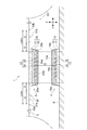
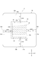
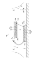
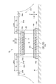
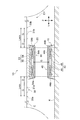
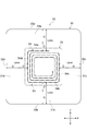
- FIG. 1 It is a sectional side view showing typically the non-contact electric supply system concerning a 1st embodiment of the present invention. It is a top view which shows the receiving coil apparatus in FIG. It is a sectional side view which shows the state which the position shift produced in the non-contact electric power feeding system of FIG. It is a sectional side view which shows the state which the position shift produced in the conventional non-contact electric power feeding system. It is a sectional side view which shows typically the non-contact electric power feeding system which concerns on 2nd Embodiment of this invention. (A) And (b) is a sectional side view which shows the other example of a receiving coil apparatus, respectively. It is a sectional side view which shows typically the non-contact electric power feeding system which concerns on 3rd Embodiment of this invention. It is a top view which shows the receiving coil apparatus in FIG.
- the same elements are denoted by the same reference numerals, and redundant descriptions are omitted.
- Each drawing is made for the purpose of explanation, and is drawn so as to particularly emphasize the target portion of the explanation. Therefore, the dimensional ratio of each member in the drawings does not necessarily match the actual one.
- the left-right direction X, the front-rear direction Y, and the up-down direction Z mean directions based on the electric vehicle EV.
- the non-contact power supply system 1 includes a power transmission coil device 4 and a power reception coil device 5, and is a system for supplying power from the power transmission coil device 4 to the power reception coil device 5 in a contactless manner.
- the power transmission coil device 4 and the power reception coil device 5 are separated in the up-down direction Z (opposing direction, that is, the second direction).
- the power transmission coil device 4 is installed on a road surface R such as a parking lot, for example.
- the power receiving coil device 5 is mounted on, for example, an electric vehicle (mobile body) EV.
- the non-contact power supply system 1 is configured to supply electric power to an electric vehicle EV that has arrived at a parking lot or the like by using magnetic coupling between coils such as a magnetic resonance method or an electromagnetic induction method.
- the power transmission coil device 4 is provided so as to protrude upward from the road surface R.
- the power transmission coil device 4 has, for example, a flat frustum shape or a rectangular parallelepiped shape.
- the power transmission coil device 4 is connected to a controller, an inverter, and the like (none of which are shown). Desired AC power generated by a DC power supply or an AC power supply is sent to the power transmission coil device 4. When AC power is sent to the power transmission coil device 4, the power transmission coil device 4 generates magnetic flux.
- the power transmission coil device 4 may be embedded in the road surface R without protruding from the road surface R.
- the power transmission coil device 4 includes a flat power transmission coil unit 13 that generates magnetic flux, and a housing 10 that houses the power transmission coil unit 13.
- the flat housing 10 includes, for example, a base 11 fixed to the road surface R and a protective cover 12 that is fixed to the base 11 and forms an accommodation space between the base 11 and the base 11.
- the base 11 and the protective cover 12 are made of resin, for example.
- the base 11 that does not face the power receiving coil device 5 may be realized by a nonmagnetic and conductive material (for example, aluminum).
- the power transmission coil unit 13 includes a ferrite plate 15 that is a rectangular plate-like magnetic member, and a conductive wire 14 wound around the ferrite plate 15.
- the conducting wire 14 which is a litz wire is wound around the ferrite plate 15 in a spiral shape.
- the conducting wire 14 may be wound directly around the ferrite plate 15 or may be wound around bobbins (wound plates) disposed on both sides of the ferrite plate 15.
- the power transmission coil unit 13 is a solenoid type coil. In the present embodiment, the power transmission coil unit 13 is arranged such that the winding axis direction (left-right direction in the drawing) is along the front-rear direction Y and the winding direction (perpendicular to the paper surface) is along the left-right direction X.
- the power receiving coil device 5 is attached to the bottom surface of the body of the electric vehicle EV (iron chassis C or the like), and faces the power transmission coil device 4 in the vertical direction (opposing direction) Z.
- the direction in which the power receiving coil device 5 faces the power transmitting coil device 4 (opposite direction) is a direction from the power receiving coil device 5 that is perpendicular to the road surface R on which the power transmitting coil device 4 is provided.
- the facing direction when the positional deviation occurs is not a direction that is obliquely directed to the road surface R from the power receiving coil device 5 to the power transmitting coil device 4.
- the power receiving coil device 5 has, for example, a flat frustum shape or a rectangular parallelepiped shape.
- the power receiving coil device 5 is connected to a controller, a rectifier and the like (none of which are shown).
- the receiving coil device 5 generates an induced current when the magnetic flux generated by the power transmitting coil device 4 is linked to the receiving coil device 5.
- the receiving coil apparatus 5 receives the electric power from the power transmission coil apparatus 4 in non-contact.
- the electric power received by the receiving coil device 5 is supplied to a load (for example, a battery).
- the power receiving coil device 5 includes a flat power receiving coil portion 23 that generates an induced current, and a housing 20 that houses the power receiving coil portion 23.
- the flat housing 20 includes, for example, a base 21 fixed to the vehicle body of the electric vehicle EV, and a protective cover 22 fixed to the base 21 and forming an accommodation space between the base 21 and the base 21.
- the base 21 and the protective cover 22 are made of resin, for example.
- the base 21 that does not face the power transmission coil device 4 may be realized by a nonmagnetic and conductive material (for example, aluminum).
- the power receiving coil unit 23 includes a ferrite plate 25 that is a rectangular plate-like magnetic member and a conductive wire 24 wound around the ferrite plate 25.
- the conducting wire 24, which is a litz wire, is spirally wound around the ferrite plate 25.
- the conducting wire 24 may be wound directly around the ferrite plate 25 or may be wound around bobbins (wound plates) disposed on both sides of the ferrite plate 25.
- the power receiving coil unit 23 is a solenoid type coil.
- the power receiving coil portion 23 is arranged so that the winding axis direction (the left-right direction in the drawing) is along the front-rear direction Y and the winding direction (the vertical direction on the paper) is along the left-right direction X.
- the shape and size of the power transmission coil unit 13 and the shape and size of the power reception coil unit 23 are equal.
- the power transmission coil device 4 and the power receiving coil device 5 a common coil device can be used.
- both ends of the power transmission coil unit 13, that is, front and rear of the front end 15a and the rear end 15b of the ferrite plate 15 The position in the direction Y matches the position in the front-rear direction Y of the front end portion 25a and the rear end portion 25b of the ferrite plate 25.
- the surface of the power transmission coil unit 13 of the power transmission coil device 4 (that is, the upper surface on the surface 12a side of the protective cover 12) and the surface of the power reception coil unit 23 of the power reception coil device 5 (that is, the surface 22a side of the protective cover 22).
- a gap length G that is an interval in the vertical direction Z is formed between the lower surface and the lower surface. This gap length G is the minimum distance between the power transmission coil unit 13 and the power reception coil unit 23.
- the surface of the power transmission coil unit 13 and the surface of the power reception coil unit 23 that define the gap length G are the surface 14 s of the conductive wire 14 of the power transmission coil unit 13 and the surface 24 s of the conductive wire 24 of the power reception coil unit 23.
- the front end portion 15a and the rear end portion 15b of the ferrite plate 15 are bent toward the power receiving coil portion 23 side, the front end portion 25a and the rear end portion 25b of the ferrite plate 25 are similarly bent toward the power transmission coil portion 13 side. It is assumed that the minimum distance between the portion 13 and the power receiving coil portion 23 is formed by the ferrite plates 15 and 25.
- the surface of the power transmission coil unit 13 that defines the gap length and the surface of the power reception coil unit 23 are the end 15a (or the end 15b) of the ferrite plate 15 of the power transmission coil unit 13 and the ferrite of the power reception coil unit 23.
- the end 25a (or end 25b) of the plate 25 may be used.
- the gap length G can vary depending on, for example, the type of electric vehicle EV and the vehicle case.
- the receiving coil device 5 includes a single aluminum plate 30 that is a non-magnetic material and is disposed between the body (chassis C or the like) of the electric vehicle EV and the receiving coil unit 23.
- the plate-like aluminum plate 30 is provided between the base 21 of the housing 20 and the iron chassis C (that is, on the back side of the power receiving coil portion 23).
- the aluminum plate 30 may be configured by a single plate material or may be configured by combining a plurality of plate materials.
- the aluminum plate 30 protrudes outside the rectangular region in which the power receiving coil portion 23 is provided in the left-right direction X and the front-rear direction Y (first direction).
- the aluminum plate 30 protrudes outward from the outer peripheral portion of the power receiving coil portion 23 (that is, the front end portion 25a, the rear end portion 25b, the right end portion 25c, and the left end portion 25d shown in FIG. 2) over the entire circumference.
- the aluminum plate 30 includes projecting portions 31a, 31b, 31c, 31d (all projecting portions) projecting over the entire circumference.
- the aluminum plate 30 covers the projection area when the power receiving coil portion 23 is projected in the vertical direction Z.
- the area of the aluminum plate 30 is wider than the projected area in the vertical direction Z of the power receiving coil portion 23.
- the aluminum plate 30 is a shield member provided to prevent the magnetic flux generated in the power transmission coil device 4 from leaking to the electric vehicle EV side.
- the possibility that the power receiving coil device 5 is misaligned with respect to the power transmitting coil device 4 is considered.
- the aluminum plate 30 is provided in a range in which the magnetic flux generated in the power transmitting coil device 4 can pass (that is, reach).
- the aluminum plate 30 protrudes from the front end portion of the power receiving coil portion 23, that is, the front end portion 25 a (one end portion) of the ferrite plate 25 corresponding to the front end portion of the power receiving coil portion 23.
- the aluminum plate 30 includes a protruding portion 31 a (first protruding portion) that protrudes outside the front end portion of the projection region of the power receiving coil portion 23.
- the length (projection length) Lmin (the distance from the front end portion 25a to the front end portion 30a) of the protrusion 31a is allowed between the power receiving coil unit 23 of the power receiving coil device 5 and the power transmission coil unit 13 of the power transmitting coil device 4. This corresponds to the sum of the allowable maximum positional deviation amount D and the gap length G described above.
- the forward protruding length of the aluminum plate 30 may be larger than the protruding length Lmin. In other words, the forward protruding length of the aluminum plate 30 may be equal to or longer than the allowable maximum positional deviation amount D plus the gap length G.
- the aluminum plate 30 protrudes from the rear end portion 25 b (one end portion) of the ferrite plate 25 corresponding to the rear end portion of the power receiving coil portion 23, that is, the rear end portion of the power receiving coil portion 23, in the front-rear direction Y.
- the aluminum plate 30 includes a protruding portion 31 b (second protruding portion) that protrudes outside the rear end portion of the projection region of the power receiving coil portion 23.
- the length (projection length) Lmin (distance from the rear end portion 25b to the rear end portion 30b) of the protrusion 31b corresponds to the sum of the allowable maximum positional deviation amount D and the gap length G described above.
- the protruding length of the aluminum plate 30 to the rear may be larger than the protruding length Lmin. In other words, the protruding length of the aluminum plate 30 to the rear may be equal to or longer than the allowable maximum positional deviation amount D plus the gap length G.
- the protruding length of the aluminum plate 30 is also set in the left-right direction X in the same manner as described above. That is, in the left-right direction X, the aluminum plate 30 protrudes from the right end portion of the power receiving coil portion 23, that is, the right end portion 25 c of the ferrite plate 25. The aluminum plate 30 protrudes from the left end portion of the power receiving coil portion 23, that is, the left end portion 25 d of the ferrite plate 25. In other words, the aluminum plate 30 includes a protruding portion 31 c that protrudes outside the right end portion of the projection region of the power receiving coil portion 23.
- the aluminum plate 30 includes a protruding portion 31 d that protrudes outside the left end portion of the projection region of the power receiving coil portion 23.
- Their protruding lengths Lmin are the receiving coil portion 23 of the receiving coil device 5 and the transmitting coil of the transmitting coil device 4. This corresponds to the sum of the allowable maximum positional deviation amount D that can be allowed between the portion 13 and the gap length G described above.
- the protruding length of the aluminum plate 30 to the left and right sides may be larger than the protruding length Lmin. In other words, the protruding length of the aluminum plate 30 to the left and right sides may be equal to or greater than the allowable maximum positional deviation amount D plus the gap length G.
- the allowable maximum positional deviation amount D is, for example, the maximum value among the predetermined positional deviation amounts so as to satisfy a predetermined power efficiency.
- the allowable maximum misregistration amount D is a maximum value of misregistration amounts obtained by measuring the power efficiency in advance by changing the misregistration and obtaining a power efficiency of a certain level or more.
- the maximum value of the positional deviation amounts such that the decrease in power efficiency with respect to the maximum power efficiency is within 5% or 10% can be used.
- the power efficiency indicates the ratio of the power at a certain location in the power receiving device including the power receiving coil device 5 to the power at the certain location in the power transmitting device including the power transmission coil device 4.
- the power efficiency is, for example, the ratio of the output power of the rectifier of the power receiving device to the input power of the inverter of the power transmission device.
- the inverter of the power transmission device refers to desired AC power transmitted from the power transmission coil device 4 to the power reception coil device 5 from DC power (output from the DC power supply, power rectified from the AC power supply, or the like). Is to be generated.
- the rectifier of the power receiving device converts AC power received by the power receiving coil device 5 into DC power (for example, power input to the battery).
- the allowable maximum positional deviation amount D is not a predetermined power efficiency, but a positional deviation at which the power receiving device including the power receiving coil device 5 can supply predetermined power (for example, 3 kW) to a load connected to the power receiving device. It can also be defined as the maximum of the quantities.
- the allowable maximum positional deviation amount D is a positional deviation amount described in a specification or a use manual of the non-contact power feeding system 1 from a viewpoint of a predetermined usage mode of the non-contact power feeding system 1.
- the allowable maximum positional deviation amount D may vary depending on the type of electric vehicle EV, the vehicle case, and the like, and examples include numerical values such as 100 mm in the front-rear direction Y and 200 mm in the left-right direction X.
- the use manual describes that “the position displacement should be within a range of 100 mm in the front-rear direction Y and 200 mm in the left-right direction X, use a non-contact power feeding system”.
- that there is no position shift can mean the positional relationship between the power transmission coil device 4 and the power reception coil device 5 in which the maximum power efficiency of the wireless power supply system 1 is realized.
- the fact that no positional deviation occurs means that the center of the surface in the front-rear direction Y of the power transmission coil unit 13 and the center of the surface in the front-rear direction Y of the power receiving coil unit 23 coincide in the vertical direction Z.
- the fact that no positional deviation has occurred may mean the positional relationship between the power transmission coil device 4 and the power receiving coil device 5 that is defined as no positional deviation in the specification or use manual of the non-contact power feeding system 1. . Deviations from these reference positions indicating that there is no positional deviation are defined as positional deviations.
- the allowable maximum positional deviation amount D different numerical values can be set in the front-rear direction Y and the left-right direction X, respectively.
- the allowable maximum positional deviation amount D in the front-rear direction Y (winding axis direction of the receiving coil device 5) is the left-right direction X (winding direction of the receiving coil device 5).
- the allowable maximum positional deviation amount D is smaller than the allowable maximum positional deviation amount D.
- the protruding length of the aluminum plate 30 in each of the front-rear direction Y and the left-right direction X is such that the magnetic flux generated in the power transmission coil device 4 can pass when the power reception coil device 5 is displaced with respect to the power transmission coil device 4. It is set within the range. That is, the aluminum plate 30 terminates in a range where the magnetic flux from the power transmission coil device 4 can reach when a positional deviation equal to or less than the allowable maximum positional deviation amount D occurs (provided only within the range). ), It does not extend to a range where the magnetic flux from the power transmission coil device 4 does not reach.
- the magnetic flux generated by the power transmission coil device 104 gathers in the chassis C of the electric vehicle EV when a positional deviation of the allowable maximum positional deviation amount D occurs. It was. As a result, the magnetic flux interlinked with the receiving coil device 105 is reduced, and the power efficiency is lowered. According to the non-contact power feeding system 1 and the power receiving coil device 5 of the present embodiment, even when a positional deviation of the allowable maximum positional deviation amount D occurs, a magnetic flux interlinking with the power receiving coil device 5 can be secured, and the power A decrease in efficiency can be suppressed.
- the protruding length of the aluminum plate 30 has a length including the gap length G.
- the swelling of the magnetic flux substantially corresponds to the gap length G. Therefore, leakage of the expanded magnetic flux toward the electric vehicle EV can be suppressed. With this configuration, the flow of magnetic flux to the electric vehicle EV is further suppressed.
- the aluminum plate 30 protrudes from the ferrite plate 25 both in the front and rear. Therefore, even if a positional shift occurs in either the front or rear direction, the magnetic flux from the power transmission coil portion 13 leaks toward the electric vehicle EV by the aluminum plate 30 protruding with a predetermined protruding length. Can be suppressed.
- the aluminum plate 30 protrudes over the entire circumference of the ferrite plate 25. Therefore, even if a positional shift occurs in any of the front, rear, left and right directions, the magnetic flux from the power transmission coil portion 13 leaks toward the electric vehicle EV by the aluminum plate 30 protruding with a predetermined protruding length. Can be suppressed.
- the solenoid-type power receiving coil unit 23 When the solenoid-type power receiving coil unit 23 is employed as in the power receiving coil device 5, the magnetic flux from the power transmitting coil unit 13 easily passes through the ferrite plate 25, and a reduction in power efficiency at the time of displacement is suppressed.
- Patent Document 2 Although there is a description of the metal frame between the power receiving coil device and the vehicle body, there is nothing about the size of the metal frame in terms of preventing magnetic flux from the power transmitting coil device 4 from passing through the chassis C. Not considered.
- the purpose is to suppress heat generation due to the magnetic flux passing through the side of the metal frame, and the range where the magnetic flux cannot reach The side portion of the metal frame is disposed on the surface.
- the size of the metal frame is set so that the side portion of the metal frame is disposed far away.
- the bigger the size, the better. Therefore, the invention described in Patent Document 2 does not examine the size regulation of the metal frame such that the metal frame is arranged in a range where the magnetic flux can reach when the position is shifted as in the present embodiment.
- size of the aluminum plate 30 can be terminated in the range which the magnetic flux from the power transmission coil apparatus 4 can reach
- the larger the size of the metal frame the better. Therefore, the eddy current passing through the flat portion (the portion other than the side portion) of the metal frame 37 becomes large.
- the non-contact electric power feeding system 1A which concerns on 2nd Embodiment is demonstrated.
- the non-contact power feeding system 1A is different from the non-contact power feeding system 1 of the first embodiment in that power transmission larger than the power receiving coil device 5 is used instead of the power transmitting coil device 4 having the same shape and size as the power receiving coil device 5.
- the coil device 4A is provided.
- the power transmission coil unit 13 ⁇ / b> A of the power transmission coil device 4 ⁇ / b> A is larger than the power reception coil unit 23 of the power reception coil device 5.
- the housing 10 ⁇ / b> A of the power transmission coil device 4 ⁇ / b> A is larger than the housing 20 of the power receiving coil device 5.
- the ferrite plate 25 of the power receiving coil device 5 is smaller than the ferrite plate 15A of the power transmission coil device 4A around which the conducting wire 14A is wound (short in the front-rear direction Y). Therefore, when the center in the front-rear direction Y of the power receiving coil device 5 and the center in the front-rear direction Y of the power transmission coil device 4A are matched (see FIG. 5), both end portions of the power transmission coil portion 13A, that is, the front end portion 15a of the ferrite plate 15A.
- the rear end portion 15b protrudes a predetermined length S from the front end portion 25a and the rear end portion 25b of the ferrite plate 25, respectively.
- the protrusion length Lmin of the aluminum plate 30A in each of the front and rear corresponds to a length obtained by adding a certain length S to the allowable maximum positional deviation amount D and the gap length G.
- the protruding length of the aluminum plate 30A may be larger than the protruding length Lmin.
- the forward and backward protruding lengths of the aluminum plate 30A may be equal to or greater than the allowable maximum positional deviation amount D and the gap length G plus a certain length S.
- the power transmission coil device 4A when the power transmission coil device 4A is larger in the front-rear direction Y than the power reception coil device 5, the power transmission coil device 4A protrudes from the power reception coil device 5 by a certain length S when viewed from the vertical direction Z. According to this configuration, it is possible to suppress a variation in the distance between the magnetic poles (the ferrite plate 15A and the ferrite plate 25) between the power transmission coil device 4A and the power reception coil device 5 at the time of positional deviation, and it is possible to suppress a decrease in power efficiency.
- the protruding length of the aluminum plate 30 includes a certain length S
- the electric vehicle is also related to the magnetic flux that is formed to protrude further outward in the front-rear direction Y than the power receiving coil portion 23 due to the protruding power transmission coil portion 13A. Leakage toward the EV can be suppressed, and the power receiving coil device 5 can be efficiently linked.
- the following examples are also conceivable as modifications of the first embodiment and the second embodiment.
- a structure in which the receiving coil device 5 is embedded in a rectangular parallelepiped recess formed in the chassis C of the electric vehicle EV may be employed.
- the power receiving coil device 5 is located at a position higher than the lowest ground clearance of the electric vehicle EV.
- the protruding length Lmin in the front-rear direction Y (and the left-right direction X) of the aluminum plate 30B provided on the back side of the power receiving coil device 5 can be set in the same manner as the protruding length Lmin in each of the embodiments described above.
- a structure in which the receiving coil device 5 is embedded in a quadrangular pyramid-shaped depression formed in the chassis C of the electric vehicle EV may be employed.
- the power receiving coil device 5 is located at a position higher than the lowest ground clearance of the electric vehicle EV.
- the protruding length Lmin in the front-rear direction Y (and the left-right direction X) of the aluminum plate 30C provided on the back side of the power receiving coil device 5 can be set in the same manner as the protruding length Lmin in each of the embodiments described above.
- the non-contact electric power feeding system 1D which concerns on 3rd Embodiment is demonstrated.
- the difference between the contactless power feeding system 1D and the contactless power feeding system 1 of the first embodiment is that, instead of the power transmitting coil device 4 and the power receiving coil device 5 in which the solenoid type power transmitting coil unit 13 and the power receiving coil unit 23 are adopted, The point is that a circular power transmission coil unit 43 and a power reception coil unit 53 are employed, and a power transmission coil device 40 and a power reception coil device 50 are provided.
- the housing 10 of the power transmission coil device 40 accommodates a ferrite plate 45 and a rectangular spiral conductive wire 44 fixed on the ferrite plate 45.
- the ferrite plate 45 is disposed on the back side of the conducting wire 44.
- the housing 20 of the power receiving coil device 50 accommodates a ferrite plate 55 and a rectangular spiral conductive wire 54 fixed on the ferrite plate 55.
- the ferrite plate 55 is disposed on the back side of the conducting wire 54.
- the shape and size of the power transmission coil unit 43 and the shape and size of the power reception coil unit 53 are equal.
- both ends of the power transmission coil unit 43 that is, the front-rear direction of the front end 44 a and the rear end 44 b of the conducting wire 44.
- the position of Y coincides with the position of the front end portion 54a and the rear end portion 54b of the conducting wire 54 in the front-rear direction Y.
- the aluminum plate 30 of the power receiving coil device 50 is the front end of the power receiving coil 53, that is, the front end of the conducting wire 54 corresponding to the front end of the power receiving coil 53.
- Projecting length Lmin (or more) protrudes from 54a (outer periphery).
- the aluminum plate 30 protrudes from the rear end portion of the power receiving coil portion 53, that is, the rear end portion 54 b (outer peripheral portion) corresponding to the rear end portion of the power receiving coil portion 53, with a protruding length Lmin (or more). .
- the aluminum plate 30 protrudes from the right end portion of the power receiving coil portion 53, that is, the right end portion 54 c of the conducting wire 54, by a protruding length Lmin (or more).
- the aluminum plate 30 protrudes from the left end portion of the power receiving coil portion 53, that is, the left end portion 54 d of the conducting wire 54, by a protruding length Lmin (or more).
- the aluminum plate 30 includes projecting portions 31a, 31b, 31c, 31d (all projecting portions) projecting over the entire circumference.
- the length (protrusion length) Lmin of the entire circumference protruding portion is the allowable maximum positional deviation amount D that can be allowed between the power receiving coil portion 53 of the power receiving coil device 50 and the power transmitting coil portion 43 of the power transmitting coil device 40, and the gap. It corresponds to the sum of the long G.
- the gap length G in the circular type coil is such that the surface 44s (the upper surface on the power receiving coil device 50 side) of the conductive wire 44 of the power transmission coil unit 43 and the surface 54s (the power transmission coil device 40 side) of the conductive wire 54 of the power receiving coil unit 53 are. The distance between the lower surface and the lower surface.
- the aluminum plate 30 protrudes over the entire circumference of the conducting wire 54. Therefore, even if a positional shift occurs in any of the front, rear, left, and right directions, the magnetic flux from the power transmission coil portion 43 leaks toward the electric vehicle EV by the aluminum plate 30 protruding with a predetermined protruding length. Can be suppressed.
- the protruding length Lmin is the same as that of the non-contact power supply system 1A (see FIG. 5).
- the protruding length of the aluminum plate 30 may not include the gap length G.
- the aluminum plate 30 may protrude only on either the front or rear side. That is, the aluminum plate 30 may include any one, two, or three of the protrusions 31a, 31b, 31c, and 31d described above.
- the aluminum plate 30 may protrude only on either the left or right side.
- the protruding lengths before and after the aluminum plate 30 may be different.
- the left and right protruding lengths of the aluminum plate 30 may be different.
- the protruding length of the aluminum plate 30 may not include the fixed length S, and the gap The length G may not be included. As long as the aluminum plate 30 has a length that includes at least the allowable maximum positional deviation amount D, a reduction in power efficiency can be suppressed even if some positional deviation occurs.
- the winding axis direction and the winding direction may be opposite to those in the above embodiment. That is, the direction in which the power receiving coil device 5 is attached may be different by 90 degrees (or any other angle) around the axis line in the vertical direction Z.
- the shape of the conducting wire 54 is not limited to a rectangular shape, and may be a circular shape.
- the ferrite plate may be omitted.
- Non-magnetic material is not limited to aluminum plate.
- the nonmagnetic material may be a copper plate, for example.
- the nonmagnetic material is not limited to a rectangular shape. When an obstacle exists in the vehicle body (moving body), a notch or the like may be provided as appropriate in the nonmagnetic material.
- the nonmagnetic material is not limited to a plate shape, and may be a block shape. Note that the present invention is not limited to the case where a nonmagnetic material is provided separately from the housing 20. For example, even if the base 21 of the housing 20 is made of a nonmagnetic material and the base 21 protrudes from the region of the power receiving coil portion 23. Good. A base 21 made of a nonmagnetic material and another nonmagnetic material disposed around the base 21 may be provided.
- the magnetic member is the ferrite plate 15, 25, 45, 55
- the magnetic member is not limited to the ferrite plate 15, 25, 45, 55.
- the magnetic member may be realized by other magnetic materials (for example, silicon steel plate, amorphous magnetic alloy, magnet).
- the magnetic member may be a soft magnetic material (for example, ferrite, silicon steel plate, amorphous magnetic alloy) in terms of improving power efficiency.
- the conductive wires 14, 24, 44, and 54 may be conductive wires other than litz wires as long as they function as a coil device for non-contact power feeding.
- the types, forms, types, materials, configurations, shapes, and dimensions of the conductive wires 14, 24, 44, and 54 can be arbitrarily selected.
- the present invention is not limited to the vehicle body of a vehicle traveling on the ground, but can be applied to other moving bodies such as an underwater vehicle. That is, the present invention can be applied to any moving body in which a positional deviation between the power transmission coil device and the power reception coil device can occur.
- the protruding portion 31a (hereinafter, the same applies to the protruding portions 31b, 31c, 31d) is expressed by a plane, but is not limited thereto.
- the protrusion 31a may be provided with one or more recesses, and the protrusion 31a may have a bumpy surface.
- a recess is provided on the surface of the protruding portion 31a facing the power transmission coil devices 4, 4A, 40.
- the eddy current hardly flows through the protrusion 31a. Then, the eddy current-dependent magnetic flux that cancels the magnetic flux generated by the power transmission coil devices 4, 4 ⁇ / b> A, 40 is reduced, and the magnetic flux linked to the power receiving coil devices 5, 50 is increased. Thereby, power efficiency improves.
Landscapes
- Engineering & Computer Science (AREA)
- Power Engineering (AREA)
- Computer Networks & Wireless Communication (AREA)
- Transportation (AREA)
- Mechanical Engineering (AREA)
- Current-Collector Devices For Electrically Propelled Vehicles (AREA)
- Electric Propulsion And Braking For Vehicles (AREA)
Abstract
受電コイル装置は、移動体に取り付けられて、送電コイル装置から非接触で電力を受け取るための受電コイル装置であって、導線を含む受電コイル部と、移動体と受電コイル部との間に配置された非磁性体と、を備える。非磁性体は、第1方向において、受電コイル部が第2方向に投影された領域の一端部の外側に突出する第1突出部を含む。第1方向は、受電コイル装置が送電コイル装置と対向する第2方向に直交する。第1突出部の長さは、受電コイル部と送電コイル装置の送電コイル部との間で許容し得る許容最大位置ずれ量以上である。
Description
本開示は、受電コイル装置および非接触給電システムに関する。本出願は、2014年10月10日に提出された日本特許出願第2014-209001号に基づいており、それに対して優先権の利益を主張するものであり、その内容全体は、参照されることによって本出願に援用される。
非接触給電システムは、送電コイル装置および受電コイル装置を備え、コイル間の電磁誘導や磁界共鳴等を利用して、非接触での送電を実現している。非接触給電システムの適用先としては、たとえば、電気自動車やプラグインハイブリッド車の給電システムが挙げられる。この場合、受電コイル装置は、車両に搭載されることになる。
従来、受電コイル装置の背面(すなわち、送電コイル装置と対向する面の反対面であり、受電コイル装置と車両との間)に導電板等を配置することが知られている(たとえば、特許文献1および特許文献2参照)。特許文献1に記載された導電板は、外部への磁界の漏洩を防止するために設けられている。これにより、送電コイル装置から発生した磁束が、車両の床面を構成する鉄板に通過することを防いでいる。特許文献2に記載された金属フレームは、受電コイル装置が他の物体に衝突して損傷することを防止するために設けられている。
しかしながら、特許文献1には、磁界の漏洩防止の観点において、導電板をどのように設けるべきか(たとえば導電板の大きさ等)について何ら検討されていない。受電コイル装置が車両等の移動体に設置される場合、移動体の停止位置によっては、導電板を受電コイル装置に設けていても、送電コイル装置の対向位置に、導電板ではなく移動体の鉄板等が存在する可能性がある。この場合、送電コイル装置からの磁束が、受電コイル装置ではなくその鉄板等を通過してしまい、電力効率の低下を招いてしまう。
本開示は、受電コイル装置の位置ずれが生じた場合であっても、電力効率の低下を抑えることができる受電コイル装置および非接触給電システムを説明する。
本発明の一態様に係る受電コイル装置は、移動体に取り付けられて、送電コイル装置から非接触で電力を受け取るための受電コイル装置であって、導線を含む受電コイル部と、移動体と受電コイル部との間に配置された非磁性体と、を備え、非磁性体は、第1方向において、受電コイル部が第2方向に投影された領域の一端部の外側に突出する第1突出部を含み、第1方向は、受電コイル装置が送電コイル装置と対向する第2方向に直交し、第1突出部の長さは、受電コイル部と送電コイル装置の送電コイル部との間で許容し得る許容最大位置ずれ量以上である。
この受電コイル装置によれば、移動体に取り付けられた受電コイル装置は、移動体が所定の位置で停止して送電コイル装置に対向した場合に、送電コイル装置から非接触で電力を受け取る。移動体と受電コイル部との間に配置された非磁性体は、受電コイル部が第2方向に投影された領域の一端部の外側に突出する第1突出部を含む。非磁性体の第1突出部の長さは、許容最大位置ずれ量以上であるため、第1方向において許容最大位置ずれ量に相当する位置ずれが生じた場合であっても、非磁性体が送電コイル部に正対することになる。よって、第1方向において受電コイル装置の位置ずれが生じることにより、受電コイル部が送電コイル部に完全に正対しない場合であっても、非磁性体によって、送電コイル部からの磁束が移動体の方へ漏れるのを抑えることができる。その結果として、送電コイル部からの磁束が受電コイル部を通過し易くなり、電力効率の低下を抑えることができる。
いくつかの態様において、送電コイル部と受電コイル部との間には、第2方向の間隔であるギャップ長が形成されており、第1突出部の長さは、許容最大位置ずれ量に当該ギャップ長を加えた長さ以上である。磁束の膨らみは、略ギャップ長に相当する。非磁性体の第1突出部の長さがギャップ長を含むため、膨らんだ分の磁束に関しても、移動体の方へ漏れるのを抑えることができる。この構成により、移動体に磁束が流れることをより一層抑えることができる。
いくつかの態様において、受電コイル部は、第1方向において送電コイル部よりも短くなっており、受電コイル部の第1方向の中心と送電コイル部の第1方向の中心とを合わせたとき、送電コイル部の一端部は受電コイル部の一端部よりも一定長突出しており、第1突出部の長さは、許容最大位置ずれ量およびギャップ長に、当該一定長を加えた長さ以上である。送電コイル部が受電コイル部よりも第1方向において大きい場合、送電コイル部は、受電コイル部よりも一定長はみ出る。非磁性体の第1突出部の長さがこの一定長を含むため、送電コイル部がはみ出たことで受電コイル部よりも第1方向に更に外側に張り出して形成される磁束に関しても、移動体の方へ漏れるのを抑えることができる。
いくつかの態様において、非磁性体は、領域の第1方向における他端部から突出する第2突出部を更に含み、第2突出部の長さは、第1突出部の長さと同様に設定される。この構成によれば、第1方向に沿ういずれの方向に位置ずれが生じた場合であっても、非磁性体の第2突出部の長さが上記のいずれかの態様と同様に設定されるため、送電コイル部からの磁束が移動体の方へ漏れるのを抑えることができる。
いくつかの態様において、非磁性体は、領域の外周部から全周にわたって突出する全周突出部を含み、全周突出部の長さは、一端部からの非磁性体の突出長さと同様に設定される。この構成によれば、どのような方向に位置ずれが生じた場合であっても、非磁性体の全周突出部の長さが上記のいずれかの態様と同様に設定されるため、送電コイル部からの磁束が移動体の方へ漏れるのを抑えることができる。
いくつかの態様において、受電コイル部は、磁性部材を含み、当該磁性部材に対して導線が巻かれたソレノイド型であり、領域の一端部は、磁性部材の第1方向における一端部に相当する。この場合、ソレノイド型の受電コイル部においても、送電コイル部からの磁束が磁性部材を通過し易くなり、位置ずれ時の電力効率の低下を抑えることができる。
いくつかの態様において、受電コイル部は、第2方向に沿う軸線を中心に導線が巻かれたサーキュラー型であり、領域の一端部は、導線の第1方向における外周部に相当する。この場合、サーキュラー型の受電コイル部においても、送電コイル部からの磁束が導線を通過し易くなり、電力効率の低下を抑えることができる。
上記したような受電コイル装置と、受電コイル装置に対向して受電コイル装置に電力を供給する送電コイル装置と、を備える非接触給電システムによれば、送電コイル装置と受電コイル装置との間で位置ずれが生じた場合であっても、電力効率の低下を抑えることができる。
本発明のいくつかの態様によれば、受電コイル装置の位置ずれが生じた場合であっても、電力効率の低下を抑えることができる。
以下、本発明の実施形態について、図面を参照しながら説明する。なお、図面の説明において同一要素には同一符号を付し、重複する説明は省略する。また、各図面は説明用のために作成されたものであり、説明の対象部位を特に強調するように描かれている。そのため、図面における各部材の寸法比率は、必ずしも実際のものとは一致しない。以下の説明において、左右方向X、前後方向Yおよび上下方向Zは、電気自動車EVを基準とした方向を意味する。
図1を参照して、本実施形態の非接触給電システム1及びこれに適用された受電コイル装置5について説明する。非接触給電システム1は、送電コイル装置4と受電コイル装置5とを備えており、送電コイル装置4から受電コイル装置5に非接触で電力を供給するためのシステムである。送電コイル装置4および受電コイル装置5は、上下方向Z(対向方向すなわち第2方向)に離間している。送電コイル装置4は、たとえば駐車場等の路面Rに設置される。受電コイル装置5は、たとえば電気自動車(移動体)EVに搭載される。非接触給電システム1は、駐車場等に到着した電気自動車EVに対し、磁界共鳴方式又は電磁誘導方式等のコイル間の磁気結合を利用して、電力を供給するように構成されている。
送電コイル装置4は、路面Rから上方に突出するように設けられている。送電コイル装置4は、たとえば扁平な錘台状や直方体状をなしている。送電コイル装置4には制御器やインバータ等(いずれも図示せず)が接続されている。直流電源や交流電源で生成された所望の交流電力は、送電コイル装置4に送られる。送電コイル装置4に交流電力が送られることにより、送電コイル装置4は、磁束を発生させる。なお、送電コイル装置4は、路面Rから突出せずに、路面Rに埋め込まれていてもよい。
送電コイル装置4は、磁束を発生させる平板状の送電コイル部13と、送電コイル部13を収容するハウジング10とを備える。扁平なハウジング10は、たとえば、路面Rに固定されたベース11と、ベース11に固定されて、ベース11との間に収容空間を形成する保護カバー12とを含む。ベース11及び保護カバー12は、例えば、樹脂製である。また、受電コイル装置5に対向しないベース11は、非磁性且つ導電性の材料(例えば、アルミニウム)で実現されてもよい。
送電コイル部13は、矩形板状の磁性部材であるフェライト板15と、フェライト板15に対して巻かれた導線14とを含む。リッツ線である導線14は、フェライト板15に対して螺旋状に巻かれている。導線14は、フェライト板15に直接巻き付けられてもよいし、フェライト板15の両面に配置されたボビン(巻付板)に巻き付けられてもよい。送電コイル部13は、ソレノイド型のコイルである。本実施形態では、巻軸方向(図示左右方向)が前後方向Yに沿い、巻線方向(紙面垂直方向)が左右方向Xに沿うように、送電コイル部13が配置されている。
受電コイル装置5は、電気自動車EVの車体(鉄製のシャーシC等)の底面に取り付けられており、上下方向(対向方向)Zにおいて送電コイル装置4に対向する。なお、受電コイル装置5が送電コイル装置4に対向する方向(対向方向)とは、受電コイル装置5から、送電コイル装置4が設けられた路面Rに垂直に向いた方向である。そのため、位置ずれが生じている場合の対向方向は、受電コイル装置5から送電コイル装置4へ路面Rに対して斜めに向く方向ではない。受電コイル装置5は、たとえば扁平な錘台状や直方体状をなしている。受電コイル装置5には制御器や整流器等(いずれも図示せず)が接続されている。受電コイル装置5は、送電コイル装置4で発生した磁束が受電コイル装置5に鎖交することによって誘導電流を発生させる。これにより、受電コイル装置5は、非接触で送電コイル装置4からの電力を受け取る。受電コイル装置5が受け取った電力は、負荷(例えば、バッテリ)に供給される。
受電コイル装置5は、誘導電流を発生する平板状の受電コイル部23と、受電コイル部23を収容するハウジング20とを備える。扁平なハウジング20は、たとえば、電気自動車EVの車体に固定されたベース21と、ベース21に固定されて、ベース21との間に収容空間を形成する保護カバー22とを含む。ベース21及び保護カバー22は、例えば、樹脂製である。また、送電コイル装置4に対向しないベース21は、非磁性且つ導電性の材料(例えば、アルミニウム)で実現されてもよい。
受電コイル部23は、矩形板状の磁性部材であるフェライト板25と、フェライト板25に対して巻かれた導線24とを含む。リッツ線である導線24は、フェライト板25に対して螺旋状に巻かれている。導線24は、フェライト板25に直接巻き付けられてもよいし、フェライト板25の両面に配置されたボビン(巻付板)に巻き付けられてもよい。受電コイル部23は、ソレノイド型のコイルである。本実施形態では、巻軸方向(図示左右方向)が前後方向Yに沿い、巻線方向(紙面垂直方向)が左右方向Xに沿うように、受電コイル部23が配置されている。
非接触給電システム1においては、送電コイル部13の形状およびサイズと、受電コイル部23の形状およびサイズとは等しくなっている。送電コイル装置4および受電コイル装置5として、共通のコイル装置を用いることができる。受電コイル装置5の前後方向Yの中心と送電コイル装置4の前後方向Yの中心とを合わせたとき、送電コイル部13の両端部、すなわちフェライト板15の前端部15aおよび後端部15bの前後方向Yの位置は、フェライト板25の前端部25aおよび後端部25bの前後方向Yの位置に一致している。さらに、送電コイル装置4の送電コイル部13の表面(すなわち、保護カバー12の表面12a側の上面)と、受電コイル装置5の受電コイル部23の表面(すなわち、保護カバー22の表面22a側の下面)との間には、上下方向Zの間隔であるギャップ長Gが形成されている。このギャップ長Gは、送電コイル部13と受電コイル部23との間の最小距離である。図1において、ギャップ長Gを規定する送電コイル部13の表面と受電コイル部23の表面とは、送電コイル部13の導線14の表面14sと受電コイル部23の導線24の表面24sである。また、仮にフェライト板15の前端部15aおよび後端部15bが、受電コイル部23側へ折れ曲がり、フェライト板25の前端部25aおよび後端部25bも同様に送電コイル部13側へ折れ曲がり、送電コイル部13と受電コイル部23との間の最小距離がフェライト板15及び25により形成されているとする。この場合は、ギャップ長を規定する送電コイル部13の表面と受電コイル部23の表面とは、送電コイル部13のフェライト板15の端部15a(または端部15b)と受電コイル部23のフェライト板25の端部25a(または端部25b)であってもよい。このギャップ長Gは、たとえば、電気自動車EVの種類や車格等に応じて変わり得る。
ここで、受電コイル装置5は、電気自動車EVの車体(シャーシC等)と受電コイル部23との間に配置された、非磁性体である1枚のアルミニウム板30を備えている。板状のアルミニウム板30は、ハウジング20のベース21と鉄製のシャーシCとの間(すなわち受電コイル部23の背面側)に設けられている。アルミニウム板30は、1枚の板材から構成されてもよいし、複数の板材が組み合わされることで構成されてもよい。
図1および図2に示されるように、アルミニウム板30は、左右方向Xおよび前後方向Y(第1方向)において、受電コイル部23が設けられた長方形の領域の外側に突出している。言い換えれば、アルミニウム板30は、受電コイル部23の外周部(すなわち図2に示される前端部25a、後端部25b、右端部25cおよび左端部25d)から、全周にわたって外方に突出している。言い換えれば、アルミニウム板30は、全周にわたって突出する突出部31a,31b,31c,31d(全周突出部)を含む。このように、アルミニウム板30は、受電コイル部23を上下方向Zに投影した場合に、その投影領域を覆っている。アルミニウム板30の面積は、受電コイル部23の上下方向Zの投影面積よりも広くなっている。
アルミニウム板30は、送電コイル装置4で発生した磁束が電気自動車EV側に漏洩するのを防止するために設けられたシールド部材である。このアルミニウム板30では、送電コイル装置4に対する受電コイル装置5の位置ずれの可能性が考慮されている。送電コイル装置4に対する受電コイル装置5の位置ずれが生じた場合に、アルミニウム板30は、送電コイル装置4で発生した磁束が通過し得る(すなわち到達し得る)範囲内に設けられている。
図1および図2を参照して、アルミニウム板30の構成についてより詳細に説明する。アルミニウム板30は、前後方向Yにおいて、受電コイル部23の前端部、すなわち受電コイル部23の前端部に相当するフェライト板25の前端部25a(一端部)から突出している。言い換えれば、アルミニウム板30は、受電コイル部23の上記投影領域の前端部の外側に突出する突出部31a(第1突出部)を含む。突出部31aの長さ(突出長さ)Lmin(前端部25aから前端部30aまでの距離)は、受電コイル装置5の受電コイル部23と送電コイル装置4の送電コイル部13との間で許容し得る許容最大位置ずれ量Dと、上記したギャップ長Gとの和に相当している。アルミニウム板30の前方への突出長さは、突出長さLminより大きくてもよい。言い換えれば、アルミニウム板30の前方への突出長さは、許容最大位置ずれ量Dにギャップ長Gを加えた長さ以上であってもよい。
アルミニウム板30は、前後方向Yにおいて、受電コイル部23の後端部、すなわち受電コイル部23の後端部に相当するフェライト板25の後端部25b(一端部)から突出している。言い換えれば、アルミニウム板30は、受電コイル部23の上記投影領域の後端部の外側に突出する突出部31b(第2突出部)を含む。突出部31bの長さ(突出長さ)Lmin(後端部25bから後端部30bまでの距離)は、許容最大位置ずれ量Dと、上記したギャップ長Gとの和に相当している。アルミニウム板30の後方への突出長さは、突出長さLminより大きくてもよい。言い換えれば、アルミニウム板30の後方への突出長さは、許容最大位置ずれ量Dにギャップ長Gを加えた長さ以上であってもよい。
図2に示されるように、左右方向Xにおいても、アルミニウム板30の突出長さは、上記と同様に設定されている。すなわち、左右方向Xにおいて、アルミニウム板30は、受電コイル部23の右端部すなわちフェライト板25の右端部25cから突出している。アルミニウム板30は、受電コイル部23の左端部すなわちフェライト板25の左端部25dから突出している。言い換えれば、アルミニウム板30は、受電コイル部23の上記投影領域の右端部の外側に突出する突出部31cを含む。アルミニウム板30は、受電コイル部23の上記投影領域の左端部の外側に突出する突出部31dを含む。それらの突出長さLmin(右端部25cから右端部30cまでの距離、および、左端部25dから左端部30dまでの距離)は、受電コイル装置5の受電コイル部23と送電コイル装置4の送電コイル部13との間で許容し得る許容最大位置ずれ量Dと、上記したギャップ長Gとの和に相当している。アルミニウム板30の左右側方への突出長さは、突出長さLminより大きくてもよい。言い換えれば、アルミニウム板30の左右側方への突出長さは、許容最大位置ずれ量Dにギャップ長Gを加えた長さ以上であってもよい。
許容最大位置ずれ量Dは、たとえば、所定の電力効率を満足し得るよう予め定められた位置ずれ量の内の最大値である。許容最大位置ずれ量Dは、具体的には、事前に、位置ずれを変化させて電力効率を測定し、一定以上の電力効率が得られる位置ずれ量の内の最大値である。許容最大位置ずれ量Dの別の例として、たとえば、最大電力効率に対する電力効率の低下が5%または10%以内であるような位置ずれ量の内の最大値とすることもできる。電力効率とは、送電コイル装置4を含む送電装置内のある箇所での電力に対する、受電コイル装置5を含む受電装置内のある箇所での電力の割合を示すものである。電力効率は、例えば、送電装置のインバータの入力の電力に対する受電装置の整流器の出力の電力の割合である。ここで、送電装置のインバータとは、送電コイル装置4から受電コイル装置5へ伝送される所望の交流電力を直流電力(直流電源からの出力や交流電源からの出力が整流された電力等)から生成するものである。受電装置の整流器とは、受電コイル装置5が受けた交流電力を直流電力(例えば、バッテリに入力される電力)に変換するものである。
また、許容最大位置ずれ量Dは、所定の電力効率ではなく、受電コイル装置5を含む受電装置が、この受電装置に接続されている負荷に所定の電力(例えば、3kW)を供給できる位置ずれ量の内の最大値と規定することもできる。
更に、許容最大位置ずれ量Dの別の例は、予め定められた非接触給電システム1の使用態様の観点から、非接触給電システム1の仕様書もしくは使用マニュアル等に記載される位置ずれ量である。許容最大位置ずれ量Dは、電気自動車EVの種類や車格等によって変わり得るが、たとえば、前後方向Yにおいて100mm、左右方向Xにおいて200mmといった数値が挙げられる。この場合、使用マニュアルには、「位置ずれは、前後方向Yで100mm、左右方向Xで200mmの範囲内であるよう、非接触給電システムをお使いください」等と記載されることが考えられる。
なお、位置ずれがないとは、本非接触給電システム1の最大電力効率が実現される送電コイル装置4と受電コイル装置5との位置関係を意味することができる。また、位置ずれが生じていないとは、送電コイル部13の前後方向Yにおける面の中心と受電コイル部23の前後方向Yにおける面の中心とが上下方向Zにおいて一致することを意味してもよい。更に、位置ずれが生じていないとは、非接触給電システム1の仕様書もしくは使用マニュアル等に位置ずれ無しとして規定される送電コイル装置4と受電コイル装置5との位置関係を意味してもよい。位置ずれがないことを示すこれらの基準位置からのずれを位置ずれとする。
許容最大位置ずれ量Dとして、前後方向Yと、左右方向Xとにおいて、それぞれ別々の数値が設定され得る。電気自動車EVのように前後方向Yに走行する移動体では、前後方向Y(受電コイル装置5の巻軸方向)の許容最大位置ずれ量Dは、左右方向X(受電コイル装置5の巻線方向)の許容最大位置ずれ量Dよりも小さくなるように決められ得る。
前後方向Yおよび左右方向Xの各方向におけるアルミニウム板30の突出長さは、送電コイル装置4に対する受電コイル装置5の位置ずれが生じた場合に、送電コイル装置4で発生した磁束が通過し得る範囲内に設定されている。すなわち、アルミニウム板30は、許容最大位置ずれ量D以下の位置ずれが生じた場合に、送電コイル装置4からの磁束が到達し得る範囲で終端しており(当該範囲内にのみ設けられており)、送電コイル装置4からの磁束が到達しない範囲までは延在していない。
このような非接触給電システム1および受電コイル装置5によれば、図3に示されるように、前後方向Yにおいて許容最大位置ずれ量Dに相当する位置ずれが生じた場合であっても、アルミニウム板30が送電コイル装置4に正対することになる。よって、前後方向Yにおいて受電コイル装置5の位置ずれが生じることにより、受電コイル部23が送電コイル部13に完全に正対していない場合であっても、アルミニウム板30のシールド効果によって、送電コイル部13からの磁束が電気自動車EVの方へ漏れるのが抑えられる。その結果として、送電コイル部13からの磁束が受電コイル部23を通過し易くなり、電力効率の低下が抑えられる。
図4に示されるように、従来の非接触給電システム100では、送電コイル装置104で発生した磁束は、許容最大位置ずれ量Dの位置ずれが生じた場合には電気自動車EVのシャーシCに集まってしまっていた。その結果、受電コイル装置105に鎖交する磁束が減少してしまい、電力効率が低下してしまっていた。本実施形態の非接触給電システム1および受電コイル装置5によれば、許容最大位置ずれ量Dの位置ずれが生じた場合でも、受電コイル装置5に鎖交する磁束を確保することができ、電力効率の低下を抑えることができる。
しかも、アルミニウム板30の突出長さがギャップ長Gを含んだ長さを有している。ここで、磁束の膨らみは、略ギャップ長Gに相当する。よって、膨らんだ分の磁束に関しても、電気自動車EVの方へ漏れるのを抑えることができる。この構成により、電気自動車EVに磁束が流れることがより一層抑えられている。
また、アルミニウム板30は、前方および後方の両方においてフェライト板25から突出している。よって、前方および後方のいずれの方向に位置ずれが生じた場合であっても、所定の突出長さで突出するアルミニウム板30により、送電コイル部13からの磁束が電気自動車EVの方へ漏れるのを抑えることができる。
さらには、アルミニウム板30は、フェライト板25の全周にわたって突出する。よって、前後左右のいずれの方向に位置ずれが生じた場合であっても、所定の突出長さで突出するアルミニウム板30により、送電コイル部13からの磁束が電気自動車EVの方へ漏れるのを抑えることができる。
受電コイル装置5のように、ソレノイド型の受電コイル部23を採用した場合において、送電コイル部13からの磁束がフェライト板25を通過し易くなり、位置ずれ時の電力効率の低下が抑えられる。
特に、送電コイル装置4からの磁束が到達し得る範囲でアルミニウム板30が終端している上記の構成では、上述した特許文献2に記載の発明に対して有利な効果を奏する。特許文献2では、受電コイル装置と車体との間の金属フレームについて記載はあるものの、送電コイル装置4からの磁束がシャーシCを通過することを防ぐという観点での金属フレームの大きさについては何ら検討されていない。特許文献2に記載の発明では、磁束が到達し得る範囲に金属フレームを配置するどころか、磁束が金属フレームの側部を通過することによる発熱を抑えることを目的とし、磁束が到達し得ない範囲に金属フレームの側部を配置するものである。つまり、本実施形態と特許文献2に記載の発明とは技術思想が真逆であり、特許文献2に記載の発明では、金属フレームの側部が遠くに配置されるように、金属フレームの大きさは大きいほど良いことになる。そのため、特許文献2に記載の発明は、本実施形態のように、位置ずれ時に磁束が到達し得る範囲に金属フレームが配置されるような金属フレームの大きさ規定について検討するものではない。また、本実施形態では、送電コイル装置4からの磁束が到達し得る範囲でアルミニウム板30の大きさを終端することができる。これにより、アルミニウム板30への磁束の通過により発生する渦電流が過剰に大きくなることを防ぎ、熱損失を抑えることができる。特許文献2に記載の発明では、金属フレームの大きさは大きいほど良いため、金属フレーム37の平面部(側部ではない部分)を通過する渦電流は大きくなってしまう。
図5を参照して、第2実施形態に係る非接触給電システム1Aについて説明する。非接触給電システム1Aが第1実施形態の非接触給電システム1と違う点は、受電コイル装置5と同形状・同サイズとされた送電コイル装置4に代えて、受電コイル装置5よりも大きい送電コイル装置4Aを備えた点である。送電コイル装置4Aの送電コイル部13Aは、受電コイル装置5の受電コイル部23よりも大きい。送電コイル装置4Aのハウジング10Aは、受電コイル装置5のハウジング20よりも大きい。言い換えれば、受電コイル装置5のフェライト板25は、導線14Aが巻かれた送電コイル装置4Aのフェライト板15Aよりも小さい(前後方向Yにおいて短い)。よって、受電コイル装置5の前後方向Yの中心と送電コイル装置4Aの前後方向Yの中心とを合わせたとき(図5参照)、送電コイル部13Aの両端部、すなわちフェライト板15Aの前端部15aおよび後端部15bは、フェライト板25の前端部25aおよび後端部25bよりも、それぞれ一定長S突出している。
前方および後方のそれぞれにおけるアルミニウム板30Aの突出長さLminは、許容最大位置ずれ量Dおよびギャップ長Gに、一定長Sを加えた長さに相当している。アルミニウム板30Aの突出長さは、突出長さLminより大きくてもよい。言い換えれば、アルミニウム板30Aの前方および後方への突出長さは、許容最大位置ずれ量Dおよびギャップ長Gに、一定長Sを加えた長さ以上であってもよい。
このように、送電コイル装置4Aが受電コイル装置5よりも前後方向Yにおいて大きい場合、送電コイル装置4Aは、上下方向Zから見た場合に、受電コイル装置5よりも一定長Sはみ出ている。この構成によれば、位置ずれ時に、送電コイル装置4Aと受電コイル装置5との磁極(フェライト板15Aおよびフェライト板25)間の距離の変動を抑えることができ、電力効率の低下が抑えられる。しかも、アルミニウム板30の突出長さが一定長Sを含むため、送電コイル部13Aがはみ出たことで受電コイル部23よりも前後方向Yに更に外側に張り出して形成される磁束に関しても、電気自動車EVの方へ漏れるのを抑え、受電コイル装置5に効率良く鎖交させることができる。
なお、上記第1実施形態および第2実施形態の変形例として、以下の例も考えられる。たとえば、図6(a)に示されるように、電気自動車EVのシャーシCに形成された直方体状の窪みに受電コイル装置5が埋め込まれたような構造であってもよい。この場合、受電コイル装置5は、電気自動車EVの最低地上高よりも高い位置に収まっている。この受電コイル装置5の背面側に設けられたアルミニウム板30Bの前後方向Y(および左右方向X)の突出長さLminは、上記した各実施形態の突出長さLminと同様に設定され得る。
また、図6(b)に示されるように、電気自動車EVのシャーシCに形成された四角錐台状の窪みに受電コイル装置5が埋め込まれたような構造であってもよい。この場合、受電コイル装置5は、電気自動車EVの最低地上高よりも高い位置に収まっている。この受電コイル装置5の背面側に設けられたアルミニウム板30Cの前後方向Y(および左右方向X)の突出長さLminは、上記した各実施形態の突出長さLminと同様に設定され得る。上記したアルミニウム板30B,30Cのように、平板状ではなく、受電コイル装置5を収容する凹部が形成された非磁性体を採用することができる。この場合でも、アルミニウム板30B,30Cが延在する長さではなく、アルミニウム板30B,30Cを上下方向Zに投影した場合の大きさ(すなわち突出長さ)が、磁束の漏洩防止の観点から重要である。
図7および図8を参照して、第3実施形態に係る非接触給電システム1Dについて説明する。非接触給電システム1Dが第1実施形態の非接触給電システム1と違う点は、ソレノイド型の送電コイル部13および受電コイル部23が採用された送電コイル装置4および受電コイル装置5に代えて、サーキュラー型の送電コイル部43および受電コイル部53が採用された送電コイル装置40および受電コイル装置50を備えた点である。送電コイル装置40のハウジング10には、フェライト板45と、フェライト板45上に固定された矩形渦巻き状の導線44とが収容されている。フェライト板45は、導線44の背面側に配置されている。受電コイル装置50のハウジング20には、フェライト板55と、フェライト板55上に固定された矩形渦巻き状の導線54とが収容されている。フェライト板55は、導線54の背面側に配置されている。送電コイル部43の形状およびサイズと、受電コイル部53の形状およびサイズとは等しくなっている。受電コイル装置50の前後方向Yの中心と送電コイル装置40の前後方向Yの中心とを合わせたとき、送電コイル部43の両端部、すなわち導線44の前端部44aおよび後端部44bの前後方向Yの位置は、導線54の前端部54aおよび後端部54bの前後方向Yの位置に一致している。
このような非接触給電システム1Dにおいても、前後方向Yにおいて、受電コイル装置50のアルミニウム板30は、受電コイル部53の前端部、すなわち受電コイル部53の前端部に相当する導線54の前端部54a(外周部)から突出長さLmin(またはそれ以上)突出している。アルミニウム板30は、受電コイル部53の後端部、すなわち受電コイル部53の後端部に相当する導線54の後端部54b(外周部)から突出長さLmin(またはそれ以上)突出している。また、左右方向Xにおいて、アルミニウム板30は、受電コイル部53の右端部すなわち導線54の右端部54cから突出長さLmin(またはそれ以上)突出している。アルミニウム板30は、受電コイル部53の左端部すなわち導線54の左端部54dから突出長さLmin(またはそれ以上)突出している。言い換えれば、アルミニウム板30は、全周にわたって突出する突出部31a,31b,31c,31d(全周突出部)を含む。全周突出部の長さ(突出長さ)Lminは、受電コイル装置50の受電コイル部53と送電コイル装置40の送電コイル部43との間で許容し得る許容最大位置ずれ量Dと、ギャップ長Gとの和に相当している。なお、サーキュラー型のコイルにおけるギャップ長Gは、送電コイル部43の導線44の表面44s(受電コイル装置50側の上面)と、受電コイル部53の導線54の表面54s(送電コイル装置40側の下面)との間の距離である。
受電コイル装置50のように、サーキュラー型の受電コイル部53を採用した場合においても、送電コイル部43からの磁束が導線54を通過し易くなり、位置ずれ時の電力効率の低下が抑えられる。
アルミニウム板30は、導線54の全周にわたって突出している。よって、前後左右のいずれの方向に位置ずれが生じた場合であっても、所定の突出長さで突出するアルミニウム板30により、送電コイル部43からの磁束が電気自動車EVの方へ漏れるのを抑えることができる。
なお、サーキュラー型の送電コイル部43、受電コイル部53において、受電コイル部53よりも送電コイル部43が大きい場合には、突出長さLminは、非接触給電システム1A(図5参照)と同様に一定長Sを含む長さとすることができる。
以上、本発明の実施形態について説明したが、本発明は上記実施形態に限られない。たとえば、アルミニウム板30の突出長さは、ギャップ長Gを含んでいなくてもよい。アルミニウム板30は、前後のいずれか一方にのみ突出していてもよい。すなわち、アルミニウム板30は、上記した突出部31a,31b,31c,31dのうちのいずれか1つ、2つまたは3つを含んでもよい。アルミニウム板30は、左右のいずれか一方にのみ突出していてもよい。アルミニウム板30の前後の突出長さが異なっていてもよい。アルミニウム板30の左右の突出長さが異なっていてもよい。
受電コイル装置5の受電コイル部23よりも送電コイル装置4の送電コイル部13の方が大きい場合において、アルミニウム板30の突出長さは、一定長Sを含んでいなくてもよく、またギャップ長Gを含んでいなくてもよい。アルミニウム板30は、少なくとも許容最大位置ずれ量Dを含んだ長さを有していれば、何らかの位置ずれが生じた場合であっても、電力効率の低下を抑えることができる。
ソレノイド型の受電コイル部を採用する場合において、巻軸方向と巻線方向とが、上記実施形態とは逆であっていてもよい。すなわち、受電コイル装置5が取り付けられる向きが、上下方向Zの軸線を中心として90度(または他の任意の角度)異なっていてもよい。サーキュラー型の送電コイル装置および受電コイル部を採用する場合において、導線54が巻かれる形状は、矩形である場合に限られず、円形であってもよい。サーキュラー型の送電コイル装置および受電コイル部を採用する場合において、フェライト板を省略してもよい。
非磁性体は、アルミニウム板に限られない。非磁性体は、たとえば銅板等であってもよい。非磁性体は、矩形状である場合に限られない。車体(移動体)に障害物が存在する場合には、非磁性体に適宜切欠き等を設けてもよい。非磁性体は、板状である場合に限られず、ブロック状であってもよい。なお、ハウジング20とは別体に非磁性体が設けられる場合に限られず、たとえば、ハウジング20のベース21が非磁性材料からなり、そのベース21が、受電コイル部23の領域から突出していてもよい。非磁性材料からなるベース21と、ベース21の周囲に配置された別の非磁性体とが設けられてもよい。
上記実施形態では、磁性部材がフェライト板15,25,45,55である場合について説明したが、磁性部材はフェライト板15,25,45,55に限定されない。磁性部材は、他の磁性材料(例えば、ケイ素鋼板、アモルファス磁性合金、磁石)で実現されてもよい。磁性部材は、電力効率向上の点で軟磁性材料(例えば、フェライト、ケイ素鋼板、アモルファス磁性合金)であってもよい。
上記実施形態では、導線14,24,44,54としてリッツ線を用いる例を示したが、これに限られない。導線14,24,44,54は、非接触給電用のコイル装置として機能する限りにおいて、リッツ線以外の導線であってもよい。たとえば、導線14,24,44,54の種類・形態・形式・材料・構成・形状・寸法は任意に選択できる事項である。
本発明は、地上を走行する車両の車体に限られず、水中航走体等の他の移動体に適用することもできる。すなわち、本発明は、送電コイル装置と受電コイル装置との位置ずれが発生し得る、あらゆる移動体に適用することができる。
上記実施形態を説明する図面では、突出部31a(以下、突出部31b,31c,31dについても同様)は、平面で表現されているが、これに限られない。突出部31aには、1つまたは複数の凹部が設けられ、突出部31aは、でこぼこの面を有していてもよい。特に、送電コイル装置4,4A,40に対向する突出部31aの面に凹部が設けられる。突出部31aに磁束が鎖交することにより、突出部31aに渦電流が流れるが、凹部により渦電流の流路が長くなり、磁気抵抗が増える。その結果、突出部31aで渦電流が流れにくくなる。すると、送電コイル装置4,4A,40によって発生する磁束を打ち消す渦電流依存の磁束が減り、受電コイル装置5,50に鎖交する磁束が増える。これにより、電力効率が向上する。
本発明のいくつかの態様によれば、受電コイル装置の位置ずれが生じた場合であっても、電力効率の低下を抑えることができる。
1 非接触給電システム
1A 非接触給電システム
1D 非接触給電システム
4 送電コイル装置
4A 送電コイル装置
5 受電コイル装置
10 ハウジング
10A ハウジング
13 送電コイル部
13A 送電コイル部
14 導線
14A 導線
15 フェライト板(磁性部材)
15A フェライト板(磁性部材)
20 ハウジング
23 受電コイル部
24 導線
25 フェライト板(磁性部材)
25a 前端部(一端部)
25b 後端部(一端部)
25c 右端部(一端部)
25d 左端部(一端部)
30 アルミニウム板(非磁性体)
30A アルミニウム板(非磁性体)
30B アルミニウム板(非磁性体)
30C アルミニウム板(非磁性体)
31a、31b、31c、31d 突出部(第1突出部、第2突出部、全周突出部)
40 送電コイル装置
43 送電コイル部
44 導線
45 フェライト板(磁性部材)
50 受電コイル装置
53 受電コイル部
54 導線
55 フェライト板(磁性部材)
D 許容最大位置ずれ量
EV 電気自動車(移動体)
G ギャップ長
S 一定長
X 左右方向(第1方向)
Y 前後方向(第1方向)
Z 上下方向(対向方向、第2方向)
Claims (8)
- 移動体に取り付けられて、送電コイル装置から非接触で電力を受け取るための受電コイル装置であって、
導線を含む受電コイル部と、
前記移動体と前記受電コイル部との間に配置された非磁性体と、を備え、
前記非磁性体は、第1方向において、前記受電コイル部が第2方向に投影された領域の一端部の外側に突出する第1突出部を含み、前記第1方向は、前記受電コイル装置が送電コイル装置と対向する前記第2方向に直交し、
前記第1突出部の長さは、前記受電コイル部と前記送電コイル装置の送電コイル部との間で許容し得る許容最大位置ずれ量以上である受電コイル装置。 - 前記送電コイル部と前記受電コイル部との間には、前記第2方向の間隔であるギャップ長が形成されており、
前記第1突出部の長さは、前記許容最大位置ずれ量に当該ギャップ長を加えた長さ以上である請求項1に記載の受電コイル装置。 - 前記受電コイル部は、前記第1方向において前記送電コイル部よりも短くなっており、
前記受電コイル部の前記第1方向の中心と前記送電コイル部の前記第1方向の中心とを合わせたとき、前記送電コイル部の一端部は前記受電コイル部の前記一端部よりも一定長突出しており、
前記第1突出部の長さは、前記許容最大位置ずれ量および前記ギャップ長に、当該一定長を加えた長さ以上である請求項2に記載の受電コイル装置。 - 前記非磁性体は、前記領域の前記第1方向における他端部から突出する第2突出部を更に含み、
前記第2突出部の長さは、前記第1突出部の長さと同様に設定される請求項1~3のいずれか一項に記載の受電コイル装置。 - 前記非磁性体は、前記領域の外周部から全周にわたって突出する全周突出部を含み、
前記全周突出部の長さは、前記一端部からの前記非磁性体の突出長さと同様に設定される請求項1~3のいずれか一項に記載の受電コイル装置。 - 前記受電コイル部は、磁性部材を含み、当該磁性部材に対して前記導線が巻かれたソレノイド型であり、
前記領域の前記一端部は、前記磁性部材の前記第1方向における一端部に相当する請求項1~5のいずれか一項に記載の受電コイル装置。 - 前記受電コイル部は、前記第2方向に沿う軸線を中心に前記導線が巻かれたサーキュラー型であり、
前記領域の前記一端部は、前記導線の前記第1方向における外周部に相当する請求項1~5のいずれか一項に記載の受電コイル装置。 - 請求項1~7のいずれか一項に記載の受電コイル装置と、
前記受電コイル装置に対向して前記受電コイル装置に電力を供給する前記送電コイル装置と、を備える非接触給電システム。
Priority Applications (3)
| Application Number | Priority Date | Filing Date | Title |
|---|---|---|---|
| EP15849049.0A EP3206281B1 (en) | 2014-10-10 | 2015-04-30 | Power reception coil device and wireless power supply system |
| CN201580043955.8A CN106575886B (zh) | 2014-10-10 | 2015-04-30 | 受电线圈装置以及非接触供电系统 |
| US15/434,600 US10315527B2 (en) | 2014-10-10 | 2017-02-16 | Power reception coil device and wireless power transfer system |
Applications Claiming Priority (2)
| Application Number | Priority Date | Filing Date | Title |
|---|---|---|---|
| JP2014209001A JP6476721B2 (ja) | 2014-10-10 | 2014-10-10 | 受電コイル装置および非接触給電システム |
| JP2014-209001 | 2014-10-10 |
Related Child Applications (1)
| Application Number | Title | Priority Date | Filing Date |
|---|---|---|---|
| US15/434,600 Continuation US10315527B2 (en) | 2014-10-10 | 2017-02-16 | Power reception coil device and wireless power transfer system |
Publications (1)
| Publication Number | Publication Date |
|---|---|
| WO2016056270A1 true WO2016056270A1 (ja) | 2016-04-14 |
Family
ID=55652897
Family Applications (1)
| Application Number | Title | Priority Date | Filing Date |
|---|---|---|---|
| PCT/JP2015/063009 WO2016056270A1 (ja) | 2014-10-10 | 2015-04-30 | 受電コイル装置および非接触給電システム |
Country Status (5)
| Country | Link |
|---|---|
| US (1) | US10315527B2 (ja) |
| EP (1) | EP3206281B1 (ja) |
| JP (1) | JP6476721B2 (ja) |
| CN (1) | CN106575886B (ja) |
| WO (1) | WO2016056270A1 (ja) |
Cited By (1)
| Publication number | Priority date | Publication date | Assignee | Title |
|---|---|---|---|---|
| JP2017200334A (ja) * | 2016-04-28 | 2017-11-02 | 昭和飛行機工業株式会社 | 外部磁気遮蔽式の非接触給電装置 |
Families Citing this family (4)
| Publication number | Priority date | Publication date | Assignee | Title |
|---|---|---|---|---|
| JP6596942B2 (ja) | 2015-06-04 | 2019-10-30 | 株式会社Ihi | コイル装置 |
| JP6794949B2 (ja) * | 2017-07-13 | 2020-12-02 | トヨタ自動車株式会社 | 車両前部構造 |
| EP3857676A1 (en) * | 2019-12-18 | 2021-08-04 | Google LLC | Wireless charging for devices with metal housings |
| CN112757924B (zh) * | 2020-12-23 | 2022-08-30 | 中兴新能源科技有限公司 | 电动汽车无线充电系统、原副边偏移量检测方法及装置 |
Citations (3)
| Publication number | Priority date | Publication date | Assignee | Title |
|---|---|---|---|---|
| JP2012204468A (ja) * | 2011-03-24 | 2012-10-22 | Fujifilm Corp | 銅配線の形成方法、配線基板の製造方法および配線基板 |
| JP2014166070A (ja) * | 2013-02-26 | 2014-09-08 | Toyota Motor Corp | 送電装置、受電装置および電力伝送システム |
| JP2014193056A (ja) * | 2013-03-28 | 2014-10-06 | Tdk Corp | ワイヤレス電力伝送装置 |
Family Cites Families (20)
| Publication number | Priority date | Publication date | Assignee | Title |
|---|---|---|---|---|
| JP5467569B2 (ja) | 2009-01-21 | 2014-04-09 | 国立大学法人埼玉大学 | 非接触給電装置 |
| JP5354539B2 (ja) | 2009-08-25 | 2013-11-27 | 国立大学法人埼玉大学 | 非接触給電装置 |
| US8410637B2 (en) * | 2009-11-30 | 2013-04-02 | Broadcom Corporation | Wireless power system with selectable control channel protocols |
| KR101753607B1 (ko) * | 2010-08-24 | 2017-07-04 | 삼성전자주식회사 | 방사형 무선 전력 전송 및 수신 장치 |
| US20120153739A1 (en) * | 2010-12-21 | 2012-06-21 | Cooper Emily B | Range adaptation mechanism for wireless power transfer |
| EP3185263A1 (en) * | 2011-01-19 | 2017-06-28 | Technova Inc. | Contactless power transfer apparatus |
| JP5813973B2 (ja) * | 2011-03-24 | 2015-11-17 | 株式会社テクノバ | 非接触給電用コイル装置 |
| US9948204B2 (en) * | 2011-05-19 | 2018-04-17 | Enphase Energy, Inc. | Method and apparatus for controlling resonant converter output power |
| WO2013099222A1 (ja) * | 2011-12-27 | 2013-07-04 | パナソニック株式会社 | 非接触充電装置 |
| JP6147741B2 (ja) * | 2012-06-05 | 2017-06-14 | 国立大学法人埼玉大学 | 非接触給電トランス |
| CN104471831B (zh) * | 2012-07-02 | 2017-11-10 | 富士机械制造株式会社 | 静电耦合方式非接触供电装置 |
| WO2014006895A1 (ja) * | 2012-07-05 | 2014-01-09 | パナソニック株式会社 | 無線電力伝送装置、無線電力送電装置および受電装置 |
| WO2014057343A1 (en) * | 2012-10-11 | 2014-04-17 | Powermat Technologies Ltd. | Inductive power transmission system and method for concurrently transmitting digital messages |
| JP6003565B2 (ja) | 2012-11-19 | 2016-10-05 | 株式会社デンソー | 非接触給電装置 |
| JP6546371B2 (ja) | 2013-03-14 | 2019-07-17 | 矢崎総業株式会社 | コイルユニット及び非接触給電装置 |
| JP6124119B2 (ja) * | 2013-03-29 | 2017-05-10 | パナソニックIpマネジメント株式会社 | 給電装置及び受電装置 |
| US9369001B2 (en) * | 2013-05-16 | 2016-06-14 | Delphi Technologies, Inc. | Magnetic field detection apparatus for a wireless power transfer system |
| JP6166598B2 (ja) * | 2013-06-26 | 2017-07-19 | キヤノン株式会社 | 送電装置、受電装置、無線電力伝送システム、制御方法、及びプログラム |
| JP6060878B2 (ja) * | 2013-11-20 | 2017-01-18 | トヨタ自動車株式会社 | 送受電部を備えた車両 |
| US9853507B2 (en) * | 2014-05-05 | 2017-12-26 | Apple Inc. | Self-locating inductive coil |
-
2014
- 2014-10-10 JP JP2014209001A patent/JP6476721B2/ja active Active
-
2015
- 2015-04-30 WO PCT/JP2015/063009 patent/WO2016056270A1/ja active Application Filing
- 2015-04-30 EP EP15849049.0A patent/EP3206281B1/en active Active
- 2015-04-30 CN CN201580043955.8A patent/CN106575886B/zh active Active
-
2017
- 2017-02-16 US US15/434,600 patent/US10315527B2/en active Active
Patent Citations (3)
| Publication number | Priority date | Publication date | Assignee | Title |
|---|---|---|---|---|
| JP2012204468A (ja) * | 2011-03-24 | 2012-10-22 | Fujifilm Corp | 銅配線の形成方法、配線基板の製造方法および配線基板 |
| JP2014166070A (ja) * | 2013-02-26 | 2014-09-08 | Toyota Motor Corp | 送電装置、受電装置および電力伝送システム |
| JP2014193056A (ja) * | 2013-03-28 | 2014-10-06 | Tdk Corp | ワイヤレス電力伝送装置 |
Cited By (1)
| Publication number | Priority date | Publication date | Assignee | Title |
|---|---|---|---|---|
| JP2017200334A (ja) * | 2016-04-28 | 2017-11-02 | 昭和飛行機工業株式会社 | 外部磁気遮蔽式の非接触給電装置 |
Also Published As
| Publication number | Publication date |
|---|---|
| US20170158066A1 (en) | 2017-06-08 |
| CN106575886A (zh) | 2017-04-19 |
| JP2016082618A (ja) | 2016-05-16 |
| EP3206281A4 (en) | 2018-05-30 |
| EP3206281A1 (en) | 2017-08-16 |
| CN106575886B (zh) | 2019-06-25 |
| US10315527B2 (en) | 2019-06-11 |
| EP3206281B1 (en) | 2020-04-22 |
| JP6476721B2 (ja) | 2019-03-06 |
Similar Documents
| Publication | Publication Date | Title |
|---|---|---|
| JP5467569B2 (ja) | 非接触給電装置 | |
| WO2016056270A1 (ja) | 受電コイル装置および非接触給電システム | |
| JP6217518B2 (ja) | ワイヤレス給電システムおよびワイヤレス電力伝送システム | |
| JP6300106B2 (ja) | 非接触電力伝送装置 | |
| JP5286445B1 (ja) | 電動式移動体の無線給電装置 | |
| KR101934018B1 (ko) | 수전 장치 및 송전 장치 | |
| JP6003565B2 (ja) | 非接触給電装置 | |
| JP2011010435A (ja) | 非接触式電力供給装置および非接触式電力供給ユニット | |
| JP6300107B2 (ja) | 非接触電力伝送装置 | |
| CA2981778C (en) | Ground-side coil unit | |
| US10673276B2 (en) | Coil device, wireless power transfer system, and auxiliary magnetic member | |
| WO2016194739A1 (ja) | コイル装置 | |
| JP6458466B2 (ja) | コイルユニット | |
| JP2014023262A (ja) | 非接触給電装置 | |
| US9748773B2 (en) | Contactless power supply device | |
| JP5253607B1 (ja) | 無線給電装置及び無線給電システム | |
| WO2014147985A1 (ja) | 非接触充電装置 | |
| JP6684579B2 (ja) | 非接触給電システム | |
| JP6285810B2 (ja) | 非接触給電装置におけるコイルユニット | |
| WO2020189077A1 (ja) | 走行中給電システム |
Legal Events
| Date | Code | Title | Description |
|---|---|---|---|
| 121 | Ep: the epo has been informed by wipo that ep was designated in this application |
Ref document number: 15849049 Country of ref document: EP Kind code of ref document: A1 |
|
| NENP | Non-entry into the national phase |
Ref country code: DE |
|
| REEP | Request for entry into the european phase |
Ref document number: 2015849049 Country of ref document: EP |