WO2016052063A1 - Dispositif d'analyse automatique - Google Patents
Dispositif d'analyse automatique Download PDFInfo
- Publication number
- WO2016052063A1 WO2016052063A1 PCT/JP2015/074987 JP2015074987W WO2016052063A1 WO 2016052063 A1 WO2016052063 A1 WO 2016052063A1 JP 2015074987 W JP2015074987 W JP 2015074987W WO 2016052063 A1 WO2016052063 A1 WO 2016052063A1
- Authority
- WO
- WIPO (PCT)
- Prior art keywords
- reagent container
- reagent
- automatic analyzer
- opening
- transport tool
- Prior art date
Links
Images


Classifications
-
- G—PHYSICS
- G01—MEASURING; TESTING
- G01N—INVESTIGATING OR ANALYSING MATERIALS BY DETERMINING THEIR CHEMICAL OR PHYSICAL PROPERTIES
- G01N35/00—Automatic analysis not limited to methods or materials provided for in any single one of groups G01N1/00 - G01N33/00; Handling materials therefor
- G01N35/02—Automatic analysis not limited to methods or materials provided for in any single one of groups G01N1/00 - G01N33/00; Handling materials therefor using a plurality of sample containers moved by a conveyor system past one or more treatment or analysis stations
- G01N35/025—Automatic analysis not limited to methods or materials provided for in any single one of groups G01N1/00 - G01N33/00; Handling materials therefor using a plurality of sample containers moved by a conveyor system past one or more treatment or analysis stations having a carousel or turntable for reaction cells or cuvettes
-
- F—MECHANICAL ENGINEERING; LIGHTING; HEATING; WEAPONS; BLASTING
- F25—REFRIGERATION OR COOLING; COMBINED HEATING AND REFRIGERATION SYSTEMS; HEAT PUMP SYSTEMS; MANUFACTURE OR STORAGE OF ICE; LIQUEFACTION SOLIDIFICATION OF GASES
- F25D—REFRIGERATORS; COLD ROOMS; ICE-BOXES; COOLING OR FREEZING APPARATUS NOT OTHERWISE PROVIDED FOR
- F25D25/00—Charging, supporting, and discharging the articles to be cooled
-
- G—PHYSICS
- G01—MEASURING; TESTING
- G01N—INVESTIGATING OR ANALYSING MATERIALS BY DETERMINING THEIR CHEMICAL OR PHYSICAL PROPERTIES
- G01N35/00—Automatic analysis not limited to methods or materials provided for in any single one of groups G01N1/00 - G01N33/00; Handling materials therefor
- G01N2035/00346—Heating or cooling arrangements
- G01N2035/00435—Refrigerated reagent storage
-
- G—PHYSICS
- G01—MEASURING; TESTING
- G01N—INVESTIGATING OR ANALYSING MATERIALS BY DETERMINING THEIR CHEMICAL OR PHYSICAL PROPERTIES
- G01N35/00—Automatic analysis not limited to methods or materials provided for in any single one of groups G01N1/00 - G01N33/00; Handling materials therefor
- G01N2035/00346—Heating or cooling arrangements
- G01N2035/00445—Other cooling arrangements
-
- G—PHYSICS
- G01—MEASURING; TESTING
- G01N—INVESTIGATING OR ANALYSING MATERIALS BY DETERMINING THEIR CHEMICAL OR PHYSICAL PROPERTIES
- G01N35/00—Automatic analysis not limited to methods or materials provided for in any single one of groups G01N1/00 - G01N33/00; Handling materials therefor
- G01N35/02—Automatic analysis not limited to methods or materials provided for in any single one of groups G01N1/00 - G01N33/00; Handling materials therefor using a plurality of sample containers moved by a conveyor system past one or more treatment or analysis stations
- G01N35/04—Details of the conveyor system
- G01N2035/0401—Sample carriers, cuvettes or reaction vessels
- G01N2035/0406—Individual bottles or tubes
- G01N2035/041—Individual bottles or tubes lifting items out of a rack for access
-
- G—PHYSICS
- G01—MEASURING; TESTING
- G01N—INVESTIGATING OR ANALYSING MATERIALS BY DETERMINING THEIR CHEMICAL OR PHYSICAL PROPERTIES
- G01N35/00—Automatic analysis not limited to methods or materials provided for in any single one of groups G01N1/00 - G01N33/00; Handling materials therefor
- G01N35/02—Automatic analysis not limited to methods or materials provided for in any single one of groups G01N1/00 - G01N33/00; Handling materials therefor using a plurality of sample containers moved by a conveyor system past one or more treatment or analysis stations
- G01N35/04—Details of the conveyor system
- G01N2035/0439—Rotary sample carriers, i.e. carousels
- G01N2035/0443—Rotary sample carriers, i.e. carousels for reagents
-
- G—PHYSICS
- G01—MEASURING; TESTING
- G01N—INVESTIGATING OR ANALYSING MATERIALS BY DETERMINING THEIR CHEMICAL OR PHYSICAL PROPERTIES
- G01N35/00—Automatic analysis not limited to methods or materials provided for in any single one of groups G01N1/00 - G01N33/00; Handling materials therefor
- G01N35/02—Automatic analysis not limited to methods or materials provided for in any single one of groups G01N1/00 - G01N33/00; Handling materials therefor using a plurality of sample containers moved by a conveyor system past one or more treatment or analysis stations
- G01N35/04—Details of the conveyor system
- G01N2035/046—General conveyor features
- G01N2035/0465—Loading or unloading the conveyor
-
- G—PHYSICS
- G01—MEASURING; TESTING
- G01N—INVESTIGATING OR ANALYSING MATERIALS BY DETERMINING THEIR CHEMICAL OR PHYSICAL PROPERTIES
- G01N35/00—Automatic analysis not limited to methods or materials provided for in any single one of groups G01N1/00 - G01N33/00; Handling materials therefor
- G01N35/02—Automatic analysis not limited to methods or materials provided for in any single one of groups G01N1/00 - G01N33/00; Handling materials therefor using a plurality of sample containers moved by a conveyor system past one or more treatment or analysis stations
- G01N35/04—Details of the conveyor system
- G01N2035/0496—Other details
Definitions
- the present invention relates to an automatic analyzer used for chemical analysis such as biochemical analysis and immunological analysis in clinical tests.
- Automatic analyzers used for chemical analysis such as biochemical analyzers and immunoanalyzers in clinical tests, hold multiple types of reagents in the reagent storage according to the analysis items, and from the reagent containers in the reagent storage at the timing of use. A predetermined amount of reagent is aspirated, mixed with the sample, and measurement is performed. When the amount of reagents held in the reagent storage is insufficient during analysis, the analysis efficiency is lowered when the analysis is stopped and the reagent is replenished at the shortage stage.
- the automatic analyzer issues a warning about reagent shortage when a reagent shortage is likely to occur, so that it is possible to prevent a situation in which the operation of the device must be stopped for replenishment or replacement of the reagent during analysis.
- Patent Document 1 an automatic loading system in which a reagent container can be attached inside is provided in a part of a fixed disk so that any of the reagent containers can be changed regardless of the operating state of the reagent fixed disk. An analyzer is described.
- Patent Document 1 does not particularly consider an apparatus structure for reliably and easily performing an operation of attaching a reagent container to a loading system.
- An object of the present invention is to provide an automatic analyzer having a structure that allows an operator to reliably and easily perform a reagent replenishment / replacement operation.
- An automatic analyzer includes a reagent container loading part having an opening for introducing a reagent container into the apparatus, a plurality of reagent container insertion slots arranged radially and a vertically movable reagent container transporting tool,
- the upper part has an opening through which the reagent container transport tool passes, and has a cool box for keeping a plurality of reagent containers cool, and an elevating mechanism for raising and lowering the reagent container transport tool.
- a plurality of guide grooves for guiding the reagent containers are arranged radially, and the plurality of radially arranged guide grooves communicate with the plurality of radially arranged slots of the reagent container transport tool at the raised position, respectively. .
- throwing-in part of an automatic analyzer The perspective schematic diagram which shows the reagent container of a sealing state.
- 1 is a schematic top view showing an embodiment of an automatic analyzer according to the present invention.
- the schematic diagram which shows the other example of the guide groove provided in a reagent container insertion part The schematic diagram which shows the other example of the guide groove provided in a reagent container insertion part.
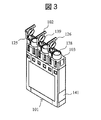
- FIGS. 2 and 3 are perspective schematic views showing an example of a reagent container used in the automatic analyzer of the present invention.
- this reagent container 101 one set is constituted by three containers.
- one set is constituted by a magnetic particle solution and two kinds of reagents.
- Each container includes a main body for storing the reagent, an opening 138 accessible to the reagent, and a lid 102 capable of sealing the opening 138.
- the entire outer shape of the reagent container 101 is a substantially rectangular parallelepiped shape having a shoulder 103, and three openings 138 are arranged above the shoulder and protrude upward.
- a round bar-like projection 126 is provided at one end of the lid 102, and the reagent container 101 is placed on the lid 102. Projects in the lateral direction.
- An RFID tag 141 is attached to the end surface of the reagent container 101.
- the built-in memory of the RFID tag 141 stores a container ID for identifying the reagent container 101, the type of reagent contained in the reagent container 101, the amount of reagent, the expiration date of the reagent, and other necessary information. ing.
- information of the reagent container 101 is obtained using RFID (Radio Frequency IDentification), but not limited to RFID, a bar code or other information reading means may be used.
- FIG. 2 is a schematic perspective view showing a sealed reagent container.
- the opening 138 is sealed by the lid 102.
- a sealing member 139 that can be inserted into the opening 138 and sealed is provided on the lid. If the opening 138 is always open, the internal reagent may evaporate or the concentration of the reagent may change. Also, if the reagent container 101 is accidentally tilted during handling, there is a risk that the reagent in the reagent container 101 will spill. These inconveniences can be reduced by sealing the opening 138 with the lid 102 and opening the lid 102 when necessary.
- FIG. 3 is a schematic perspective view showing the reagent container in an open state.
- the lid 102 is pivoted about the hinge 125 as a rotation axis, so that the lid 102 is opened from the projection 126. At this time, the sealing member 139 is completely removed from the opening 138, and the lid 102 is opened at a large angle around the hinge 125.
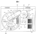
- FIG. 4 is a schematic top view showing an embodiment of the automatic analyzer according to the present invention.
- the automatic analyzer according to the present embodiment stirs a reagent cooler 105 having a reagent loader mechanism 104 that automatically loads and unloads the reagent container 101, and a reagent (particularly, a reagent containing magnetic particles) in the reagent cooler.
- Magnetic particle agitation device 107 magazine 130 for holding a plurality of consumables necessary for analysis (for example, reaction containers and sample dispensing tips), reaction container / sample dispensing for transporting consumables on magazine 130 to an appropriate position With the chip transport device 131 and the sample dispensing chip mounted, the sample dispensing device 132 for dispensing a predetermined amount of sample from the sample container in the sample rack 133 on the transport line to the reaction container, and the reaction container containing the sample.
- a reaction tank 134 held at a predetermined temperature
- a reagent dispensing device 108 that sucks a predetermined amount of reagent in the reagent cooler 105 and discharges it into the reaction container, and the sample and reagent in the reaction container are mixed.
- the reagent cooler 105 is provided with an RFID 143 for reading information of an RFID tag attached to the reagent container in a contactless manner at an access position by the reagent dispensing device 108.
- the reagent cooler 105 is hermetically sealed with a lid (not shown) on the upper surface, but the reagent loader mechanism 104, the stirrer of the magnetic particle stirring device 107, and the probe of the reagent dispensing device 108 are passed through a part of the lid. An opening is provided to allow
- a reagent disk 127 having a plurality of slots in which reagent containers can be installed is provided inside the reagent cool box 105. By rotating the reagent disk 127, any reagent container 101 can be attached to each mechanism. It can be transported to the access position.
- the reagent container moving device 128 can move the reagent container 101 between the reagent loader mechanism 104, the slot of the reagent disk 127, and the stirring position by the magnetic particle stirring device 107.
- the reagent container lid opening / closing device 129 opens the lid of the reagent container 101 at an appropriate timing before processing by the magnetic particle stirring device 107 or the reagent dispensing device 108 and closes after the use of the reagent after the processing is completed. be able to.
- the reagent container 101 used for the analysis is set on the reagent disk 127 in the reagent cold storage 105.
- the operator inserts the reagent container 101 into the reagent loader mechanism 104.
- the reagent loader mechanism 104 is lowered and returned to the reagent cooler 105, and the reagent container 101 mounted on the reagent loader mechanism 104 is moved to the slot of the reagent disk 127 by the reagent container moving device 128.
- the reagent container 101 moved to the reagent disk 127 is used for analysis processing.
- the up and down movement of the reagent loader mechanism 104 may be performed from a screen for operating the automatic analyzer, or a switch may be installed in the vicinity of the reagent loader mechanism 104 and operated by the switch operation. good. Details of the reagent loader mechanism 104 and a method for inserting the reagent container 101 into the reagent loader mechanism 104 will be described later.
- the analysis process is started after the introduction of the reagent container 101 necessary for the analysis is completed.
- the analysis process is automatically executed according to a predetermined procedure under the control of the host computer.
- the reaction vessel / sample dispensing tip transport device 131 transfers the reaction vessel mounted in the magazine 130 into the reaction tank 134, and the sample dispensing tip is further transferred to the probe of the sample dispensing device 132. Transfer to the position to attach to the tip.
- the reaction tank 134 can be driven to rotate horizontally while holding a plurality of reaction containers.
- the reaction tank 134 rotates to the reagent dispensing position, and the reagent in the reagent container 101 is first transferred to the reaction container by the reagent dispensing device 108. Dispensed by the determined amount.
- the host computer communicates with the RFID 143 that has read the information of the RFID tag 141 attached to the reagent container 101 to confirm that the reagent dispensed into the reaction container is a desired reagent.
- the sample dispensing device 132 equipped with the sample dispensing chip aspirates the sample from the sample container mounted on the sample rack 133, and the reaction container into which the reagent is dispensed is rotated to the sample dispensing position by the rotation of the reaction tank 134. The sample is dispensed into the reaction container by the sample dispensing device 132.
- the reaction vessel containing the reagent and the sample is kept warm in the reaction vessel 134 for a certain period of time.
- the reaction container again moves to the reagent dispensing position, and the magnetic particles in the reagent container 101 are dispensed by the reagent dispensing apparatus 108.
- the reaction vessel 134 rotates, the reaction vessel on the reaction vessel 134 is moved to the reaction solution stirring device 135 by the reaction vessel / sample dispensing chip transfer device 131, and the reaction vessel stirring device 135 causes the magnetism in the reaction vessel to move. Agitate the particles and the reagent and specimen reacted for a certain period of time.
- reaction vessel is returned again to the reaction vessel 134 by the reaction vessel / sample dispensing chip transfer device 131 and further reacted for a certain period of time in the reaction vessel 134, and then the reaction solution (reagent / sample / Magnetic particles) are introduced into the detection unit 137, and detection is performed.
- the reaction liquid cleaning device 136 may perform a reaction liquid cleaning process for the purpose of removing impurities contained in the reaction liquid before the detection process. This series of processes can be performed continuously.
- the host computer manages the type, remaining amount, expiration date, and the like of the reagent held by each reagent container in the reagent cooler 105, and displays warnings regarding reagent replenishment and replacement at an appropriate timing.
- the reagent container 101 in which the reagent is accommodated is mounted in the reagent cold storage 105 having the cold keeping function for analysis. Loading / unloading of the reagent container 101 to / from the reagent cooler 105 is performed using a reagent loader mechanism 104 capable of mounting a plurality of sets of reagent containers 101.
- a reagent loader mechanism 104 capable of mounting a plurality of sets of reagent containers 101.
- a plurality of sets of reagent containers 101 are mounted and the reagent disk 127 can be rotated.
- the reagent container 101 can be moved between the reagent loader mechanism 104 and the reagent disk 127.
- a reagent container lid opening / closing device 129 capable of opening and closing the lid 102 of the reagent container 101 in the process is provided.
- a magnetic particle agitation device 107, a reagent dispensing device 108, and the like are provided outside the reagent cooler 105, and these devices are located at an opening provided in a lid that covers the upper part of the reagent cooler 105, and a reagent disk.
- the reagent container 101 mounted on 127 can be accessed.
- the reagent disk 127 can be driven to rotate in the horizontal direction.
- the mounted reagent container 101 is moved to the stirring and dispensing position, and the lid 102 of the reagent container 101 is opened by the reagent container lid opening / closing device 129.
- the magnetic particle stirring device 107 stirs the magnetic particles in the reagent container 101
- the reagent dispensing device 108 dispenses and dispenses the reagent contained in the reagent container 101.
- the lid 102 of the reagent container 101 after the stirring of magnetic particles, reagent dispensing, and dispensing is closed by the reagent container lid opening / closing device 129. Processing and operation by each device in the automatic analyzer are performed under the control of the host computer.
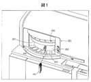
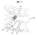
- FIG. 1 is a schematic diagram showing an example of a reagent container loading part of an automatic analyzer.
- the reagent container 101 is carried into the reagent cooler 105 of the automatic analyzer through the reagent container loading unit 201.
- the reagent container loading unit 201 of the present embodiment has an approach region configured by an opening 202 through which the reagent container is introduced into the apparatus, and a space between an upper surface 203 and a lower surface 204 in front of the opening connected to the opening 202.
- the reagent loader mechanism 104 that holds the reagent container 101 and conveys it into the reagent cooler 105 of the automatic analyzer is installed in the apparatus main body inside the opening 202 and does not appear in FIG.
- FIG. 1 shows a state in which the opening 202 is closed by a shielding member provided in the reagent container transport tool of the reagent loader mechanism 104, as will be described later.
- a plurality of guide grooves 205 for guiding the reagent container are radially arranged on the lower surface in front of the opening connected to the opening 202.
- the guide groove 205 is for sliding the lower end portion of the reagent container 101 therein and guiding it toward the inside of the opening 202.
- the five guide grooves are along the insertion direction of the reagent container. Is provided.
- a display lamp 206 for indicating the state is provided at the upper part of the front surface of the reagent container loading part and above each guide groove.
- FIG. 5 to FIG. 7 are schematic cross-sectional views showing the procedure for bringing the reagent container into the automatic analyzer of this embodiment.
- an approach region in front of the opening of the reagent container loading unit, a reagent loader mechanism 104, and a reagent cold storage 105 are shown.
- the procedure for carrying the reagent container into the reagent cooler from the opening of the reagent container loading unit will be described with reference to these drawings.
- FIG. 5 is a schematic cross-sectional view of the automatic analyzer when the reagent container transport tool 210 of the reagent loader mechanism 104 is in the raised position.
- the reagent loader mechanism 104 includes a reagent container transport tool 210 that can move up and down and a lifting mechanism 220 that lifts and lowers the reagent container transport tool.
- the reagent container transporter 210 has a plurality (five in the present embodiment) of slots 211 for inserting reagent containers arranged in a radial pattern, and the cross section is L-shaped above the slot 211.
- the shielding member 212 is provided. The reagent container transport tool 210 can be moved between the raised position shown in FIG. 5 and the lowered position shown in FIG.
- the reagent cooler 105 has an opening 106 for allowing the reagent container transporter 210 to pass therethrough and includes a rotatable reagent disk 127 inside.
- the reagent disk 127 has an annular reagent container placement region on the outer peripheral side.
- An RFID 142 is provided on a side surface of the opening 106.
- the automatic analyzer of the present embodiment has a retreat space in which the shielding member 212 is retreated from the opening of the reagent container insertion unit above the reagent container transporter 210.
- the opening 106 provided in the reagent cooler 105 is not closed by the reagent container transport tool 210 and is opened in this state.
- the guide groove 205 of the reagent container loading unit 201 communicates with the slot 211 of the reagent container transport tool 210. Therefore, the operator can hold the reagent container with one hand, slide it along the guide groove 205 as it is, bring it to the reagent container transport tool 210 of the reagent loader mechanism 104, and insert the reagent container into the slot 211 with certainty.
- the slot 211 of the reagent container transporter 210 is cut out so that a part of the side wall forming the slot does not touch the operator's hand or finger that holds the reagent container and inserts it into the slot.
- the notch 213 is provided at a position corresponding to the position of the operator's hand that holds the reagent container. Therefore, the operator can safely and reliably mount the reagent container in the slot 211 of the reagent container transporting tool 210 without the hand holding the reagent container being obstructed by the wall forming the slot. In other words, the provision of the notch 213 makes it easier for a finger to enter the reagent container transport tool 210, and it is easy to remove the reagent container from the slot when the reagent container is inserted into the slot.
- the reagent container transport tool 210 of the reagent loader mechanism has five slots as the number of the guide grooves 205 provided in the reagent container insertion portion 201 so that the five reagent containers can be held radially.
- the slot width is almost the same as the width of the reagent container and there is not enough room, and the internal viewing state may not be sufficient. It is difficult to insert it quickly and reliably into the slot of the container transporter.
- the guide grooves arranged radially when the plurality of reagent containers are grasped by hand and inserted, the reagent containers do not interfere with each other, and the reagent containers can be prevented from being unexpectedly dropped or spilled.
- the light from the LED 222 held on the substrate 221 provided on the back surface of the reagent container loading unit 201 is guided to the upper surface of the reagent container loading unit 201 by the light guide member 223.
- the light guide member may be omitted by exposing the LED to the upper surface of the reagent container loading unit 201.
- the contact sensor 224 may be provided on the innermost wall where the reagent container 101 of the reagent container insertion slot 211 of the reagent container transporting tool 210 contacts.
- the reagent container transport tool 210 is lowered in that state. Then, the reagent container 101 is sandwiched between adjacent members, and the subsequent processing cannot be performed, or the member is damaged.
- the contact sensor 224 is for dealing with this problem.
- the LED 222 corresponding to the input position that is, the display lamp 206 is turned on to notify the operator.
- the operator can confirm that the reagent container is completely inserted by pushing the reagent container 101 into the slot of the reagent container transport tool 210 until the display lamp 206 is lit.
- FIG. 6 is a schematic cross-sectional view of the automatic analyzer when the reagent container transport tool 210 of the reagent loader mechanism 104 is in the raised position, as in FIG. FIG. 6 shows a state in which the necessary reagent container 101 has been inserted into the reagent container transport tool 210 of the reagent loader mechanism 140. As shown in the figure, the reagent container 101 is fully pushed into the slot of the reagent container transporter 210 and inserted. By providing the guide groove 205 in the reagent container loading unit 201 and the notch 213 in the slot 211, the operator can easily and reliably insert the reagent container 101 into the reagent container transport tool 210 of the reagent loader mechanism 104. It is supposed to be.
- the reagent container transporter 210 is then moved down into the reagent cooler 105 through the opening 106 at the top of the reagent cooler 105 by the lifting mechanism 220.
- the reagent container transport tool 210 moves downward through the opening 106, information on the RFID tag included in the reagent container 101 inserted into the reagent container transport tool 210 is read by the RFID 142.
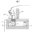
- FIG. 7 is a schematic cross-sectional view of the automatic analyzer when the reagent container transport tool 210 of the reagent loader mechanism 104 is in the lowered position.
- the slot 211 that holds the reagent container of the reagent container transport tool 210 is positioned in the reagent cooler 105.
- the space that can be formed above the shielding member 212 of the reagent container transporter 210 is a retreat space in which the shielding member 212 is retracted from the opening 202 of the reagent container insertion unit.
- the vertical portion of the shielding member 212 provided in the reagent container transporting tool 210 closes the opening 202 of the reagent container inserting unit 201, thereby realizing the inaccessible state shown in FIG.
- the horizontal portion of the shielding member 212 closes the opening 106 at the top of the reagent cooler 105. That is, in the state where the reagent container transport tool 210 of the reagent loader mechanism 104 is at the lowest position, unnecessary access to the inside of the apparatus from the reagent container loading unit 201 is prevented and the cooling efficiency of the reagent cooler 105 is improved.
- the reagent cooler 105 can be sealed.
- the door 202 is provided outside the guide groove 205 to close the opening 202 on the center side of the radial shape as in this embodiment. Since the area for closing the opening is smaller than that for closing 202 and the member can be omitted, it contributes to cost reduction.
- the reagent container 101 inserted in the slot 211 of the reagent container transporter 210 is moved to the reagent disk 127 by the reagent container moving device 128.
- Reagent container moving device 128 can be implemented using known techniques.
- the reagent container moving device 128 shown in FIG. 4 includes a gripping part that sandwiches and grips the reagent container from the side surface, and a telescopic part that moves the gripping part in the radial direction, and includes a reagent container transporting tool of the reagent loader mechanism 104 The reagent container is transferred between the slot 211 of 210 and the slot of the reagent disk 127.
- a procedure reverse to the procedure shown in FIGS. 5 to 7 is executed.
- the reagent container 101 to be discharged is moved to the slot 211 of the reagent container transport tool 210 of the reagent loader mechanism 104 by using the reagent container moving device 128 in the reagent cool box 105.
- the reagent loader mechanism 104 is raised, the operator inserts his / her hand through the opening of the reagent container loading unit 201, grasps the reagent container 101 mounted in the slot 211 of the reagent container transport tool 210 of the reagent loader mechanism 104, and moves it outside the apparatus. Take out.
- the slot of the reagent container placement area on the reagent disk 127 is set on the outer peripheral side of the circular disk, and the reagent container transport tool 210 of the reagent loader mechanism 104 is the reagent disk 127.
- the inside of the reagent container mounting area is lowered. Therefore, the reagent container delivered from the slot of the reagent container transport tool 210 to the reagent disk 127 inside the reagent cooler 105 is moved from the center side to the outer peripheral side along the radial direction of the reagent disk 127.
- the reagent container stored in the reagent cooler from the outside via the reagent container loading part of the automatic analyzer is horizontally inserted into the slot of the reagent container transport tool of the reagent loader mechanism 104 along the radial guide groove.
- Movement (FIG. 5) vertical movement accompanying the lowering of the reagent container transport tool by the lifting mechanism (FIG. 6), horizontal movement transferred from the reagent container transport tool slot of the reagent loader mechanism to the outer peripheral region of the reagent disk
- the reagent is introduced into the reagent cooler by following a U-shaped movement path.
- FIG. 8 and 9 are schematic diagrams showing the relationship between the entire reagent loader mechanism and the guide unit. In order to show the entire reagent loader mechanism, the surrounding structure is removed and shown in a simplified manner.
- FIG. 8 corresponds to FIG. 5 and is a schematic view of a state in which the reagent container transport tool of the reagent loader mechanism is in the raised position.
- FIG. 9 corresponds to FIG. 7 and the reagent container transport tool of the reagent loader mechanism is in the lowered position. It is a schematic diagram of a certain state.
- the reagent container carrier 210 is provided with five slots 211 for inserting reagent containers, the same number as the guide grooves 205.
- the slot 211 for inserting the reagent container of the reagent container transport tool 210 is exposed at the opening 202 of the reagent container loading section 201, The reagent container 101 can be inserted into the slot 211 of the reagent container transporter 210 along the guide groove 205.
- the five guide grooves 205 arranged radially communicate with the five slots of the reagent container transporter 210 also arranged radially.
- the radially arranged slots 211 and the radially arranged guide grooves 205 constitute a radially shaped groove that is completely continuous.
- the side wall forming the slot of the reagent container transporter 210 is cut off on the side facing the operator so that the operator's hand holding the reagent container does not hit. Therefore, an operator who holds the reagent container to be inserted into the slot with one hand puts the bottom of the reagent container into the guide groove 205 and slides the reagent container along the guide groove 205 toward the back of the opening 202 while holding the reagent container.
- the reagent container can be safely and reliably inserted into the slot 211 simply by going on.
- the reagent container charging portion is formed in an arc shape. Accordingly, the arrangement region of the guide groove 205 provided in the reagent container insertion unit 201 and the opening 202 are also arranged in an arc shape, and the surface of the shielding member 212 provided in the reagent container transporter 210 for closing the opening 202 is a cylindrical surface. It has become.
- the shielding member 212 provided on the reagent container transport tool 210 is also lowered from the upper retreat space to the position of the opening 202 of the reagent container loading portion as shown in FIG. Then, the opening 202 is closed. At this time, the shielding member 212 closes the opening of the upper part of the reagent cooler 105 and seals it.
- FIG. 10 is a schematic diagram showing another example of a guide groove provided in the reagent container loading part.
- a plurality of guide grooves 205 for guiding the reagent containers are radially arranged on the lower surface 204 of the approach region provided in front of the opening provided in the reagent container loading unit 201, and the upper surface 203 of the approach region.
- guide grooves 207 facing the guide grooves 205 on the lower surface are arranged radially. Since the reagent container 101 is slid with the upper and lower ends fixed to the upper and lower guide grooves 207 and 205 provided in the approach region, the reagent container 101 can be inserted into the slot of the reagent container transporter 210 with higher accuracy.
- the guide groove 205 provided on the lower surface of the reagent container loading unit 201 has a plurality of convex members 231 arranged on a plane serving as a base, and uses the space between the convex members as a guide groove. It is a form.
- the planar shape of the convex member 231 is a substantially trapezoid.
- FIG. 11 is a schematic diagram showing another example of a guide groove provided in the reagent container loading part.
- the guide groove 205 provided radially on the lower surface 204 of the approach region in front of the opening of the reagent container loading unit 201 has a wide width on the front entrance side, and thereafter has a constant width and a position where the back is higher. It has a shape that is guided up to.
- the guide groove 205 of this embodiment since the width on the front entrance side is wide, it is easy to insert the reagent container 101 into the guide groove 205 for the first time.
- the guide groove 205 of this embodiment is also a form in which a plurality of convex members 232 are arranged on a plane serving as a base, and the space between the convex members is used as a guide groove.
- the planar shape of the convex member 232 is a shape in which the corners on the near side of the trapezoid are chamfered, and the height on the far side is higher than the near side.
- FIG. 12 is a schematic diagram showing another example of a guide groove provided in the reagent container loading part.
- the guide grooves 205 and 207 are provided radially on the upper and lower surfaces of the approach region in front of the opening of the reagent container loading unit 201.
- the guide groove 205 provided on the lower surface of the reagent container insertion portion is a form in which a groove formed by digging down the base plane is used as a guide groove.
- the guide groove 205 is wide on the front side, and has a shape that allows easy insertion when the reagent container 101 is first placed in the guide groove 205.
- the groove is formed so that the depth gradually increases from the plane serving as the base, the portion between the groove and the groove does not collide with the hand during insertion.
- FIG. 13 is a schematic diagram showing another example of a guide groove provided in the reagent container inserting portion.
- guide grooves 205 and 207 are provided radially on the upper and lower surfaces of the approach region in front of the opening of the reagent container loading unit 201.
- an example is shown in which the guide groove 205 starts from the end of the lower surface provided in the reagent container loading unit 201.
- the reagent container transport tool 210 of the reagent loader mechanism 104 may have an apparatus configuration in which less than five or five or more reagent containers can be mounted.
- this invention is not limited to the above-mentioned Example, Various modifications are included.
- the above-described embodiments have been described in detail for easy understanding of the present invention, and are not necessarily limited to those having all the configurations described.
- a part of the configuration of one embodiment can be replaced with the configuration of another embodiment, and the configuration of another embodiment can be added to the configuration of one embodiment.
- Reagent container 104 Reagent loader mechanism 105
- Reagent cooler 127 Reagent disc 201
- Reagent container loading unit 202 Opening 205 Guide groove 206
- Guide groove 210 Reagent container transport tool 211
- Slot 212 Shield member 213 Notch 220 Lifting mechanism 221
Landscapes
- Chemical & Material Sciences (AREA)
- Engineering & Computer Science (AREA)
- Physics & Mathematics (AREA)
- General Health & Medical Sciences (AREA)
- Analytical Chemistry (AREA)
- Pathology (AREA)
- Immunology (AREA)
- Chemical Kinetics & Catalysis (AREA)
- Health & Medical Sciences (AREA)
- Life Sciences & Earth Sciences (AREA)
- General Physics & Mathematics (AREA)
- Biochemistry (AREA)
- Combustion & Propulsion (AREA)
- Mechanical Engineering (AREA)
- General Engineering & Computer Science (AREA)
- Thermal Sciences (AREA)
- Automatic Analysis And Handling Materials Therefor (AREA)
Abstract
L'invention concerne un dispositif d'analyse automatique possédant une structure qui permet à un opérateur d'effectuer de manière fiable et aisée un réapprovisionnement et un remplacement de réactif ; le dispositif comporte une partie d'entrée de récipient à réactif 201 comportant une ouverture 202 permettant d'introduire un récipient à réactif 101 dans le dispositif, un outil de transport de récipient à réactif qui comporte une pluralité de fentes d'insertion de récipient à réactif, disposées radialement, et est capable de monter et descendre, un réfrigérateur qui a une ouverture dans sa partie supérieure pour permettre à l'outil de transport de récipient à réactif de passer à travers celui-ci et refroidit une pluralité des récipients à réactif, et un mécanisme de levage et abaissement pour lever et abaisser l'outil de transport de récipient à réactif. L'unité d'insertion de récipient à réactif comporte, au niveau de la surface inférieure avant de l'ouverture, une pluralité de rainures de guidage disposées radialement 205 permettant de guider les récipients à réactif, et les rainures de guidage communiquent respectivement avec la pluralité de fentes d'insertion de récipient à réactif disposées radialement de l'outil de transport de récipient à réactif lorsque l'outil de transport de récipient à réactif se trouve dans une position levée.
Priority Applications (3)
| Application Number | Priority Date | Filing Date | Title |
|---|---|---|---|
| CN201580039488.1A CN106537152B (zh) | 2014-09-30 | 2015-09-02 | 自动分析装置 |
| EP15847562.4A EP3203242B1 (fr) | 2014-09-30 | 2015-09-02 | Dispositif d'analyse automatique |
| US15/326,769 US10267816B2 (en) | 2014-09-30 | 2015-09-02 | Automatic analysis device |
Applications Claiming Priority (2)
| Application Number | Priority Date | Filing Date | Title |
|---|---|---|---|
| JP2014-200522 | 2014-09-30 | ||
| JP2014200522A JP6348816B2 (ja) | 2014-09-30 | 2014-09-30 | 自動分析装置 |
Publications (1)
| Publication Number | Publication Date |
|---|---|
| WO2016052063A1 true WO2016052063A1 (fr) | 2016-04-07 |
Family
ID=55630107
Family Applications (1)
| Application Number | Title | Priority Date | Filing Date |
|---|---|---|---|
| PCT/JP2015/074987 WO2016052063A1 (fr) | 2014-09-30 | 2015-09-02 | Dispositif d'analyse automatique |
Country Status (5)
| Country | Link |
|---|---|
| US (1) | US10267816B2 (fr) |
| EP (1) | EP3203242B1 (fr) |
| JP (1) | JP6348816B2 (fr) |
| CN (1) | CN106537152B (fr) |
| WO (1) | WO2016052063A1 (fr) |
Families Citing this family (9)
| Publication number | Priority date | Publication date | Assignee | Title |
|---|---|---|---|---|
| KR102289821B1 (ko) * | 2014-10-23 | 2021-08-13 | 삼성전자주식회사 | 수송 장치 및 이를 이용하는 수송 방법 |
| JP6886837B2 (ja) * | 2017-02-22 | 2021-06-16 | 株式会社日立ハイテク | 自動分析装置 |
| JP6921674B2 (ja) * | 2017-07-28 | 2021-08-18 | テラメックス株式会社 | 試験片収納容器連続処理装置 |
| US11402397B2 (en) | 2018-02-13 | 2022-08-02 | Hitachi High-Technologies Corporation | Automatic analyzer |
| CN110361555A (zh) * | 2018-03-26 | 2019-10-22 | 成都深迈瑞医疗电子技术研究院有限公司 | 试剂装载组件、样本试剂装载装置及化学发光免疫分析仪 |
| IT201900000166A1 (it) * | 2019-01-08 | 2020-07-08 | Ima Spa | Apparato e metodo per la gestione automatizzata di dispositivi rivelatori di carica batterica. |
| JP7224966B2 (ja) * | 2019-03-05 | 2023-02-20 | 株式会社日立ハイテク | 自動分析装置 |
| CN114279147A (zh) * | 2021-01-15 | 2022-04-05 | 青岛海特生物医疗有限公司 | 疫苗冷藏取放一体库 |
| CN114279148A (zh) * | 2021-01-15 | 2022-04-05 | 青岛海特生物医疗有限公司 | 疫苗存储发放系统及接种方法 |
Citations (3)
| Publication number | Priority date | Publication date | Assignee | Title |
|---|---|---|---|---|
| EP1225450A1 (fr) * | 2001-01-02 | 2002-07-24 | Randox Laboratories Ltd. | Appareil de distribution ou de remplissage en réactif, et récipient à réactif |
| JP2003262642A (ja) * | 2002-03-07 | 2003-09-19 | Hitachi High-Technologies Corp | 自動分析装置 |
| JP2012189611A (ja) * | 2009-07-29 | 2012-10-04 | F. Hoffmann-La Roche Ag | 自動分析器 |
Family Cites Families (7)
| Publication number | Priority date | Publication date | Assignee | Title |
|---|---|---|---|---|
| US1225450A (en) * | 1916-07-18 | 1917-05-08 | Alice Macleod | Composition of fruit matter for food production. |
| US7628954B2 (en) * | 2005-05-04 | 2009-12-08 | Abbott Laboratories, Inc. | Reagent and sample handling device for automatic testing system |
| JP4975407B2 (ja) | 2006-10-10 | 2012-07-11 | シスメックス株式会社 | 分析装置 |
| JP6032672B2 (ja) * | 2013-01-11 | 2016-11-30 | 株式会社日立ハイテクノロジーズ | 自動分析装置 |
| JP5829643B2 (ja) | 2013-03-29 | 2015-12-09 | シスメックス株式会社 | 分析装置 |
| EP3037825B1 (fr) | 2013-08-20 | 2019-04-17 | Hitachi High-Technologies Corporation | Analyseur automatique |
| EP3080615B1 (fr) * | 2013-12-13 | 2018-07-25 | Roche Diagnostics GmbH | Support de récipient de réactif pour instrument d'analyse, système d'alimentation en réactif d'un tel instrument et ledit instrument d'analyse |
-
2014
- 2014-09-30 JP JP2014200522A patent/JP6348816B2/ja active Active
-
2015
- 2015-09-02 US US15/326,769 patent/US10267816B2/en active Active
- 2015-09-02 EP EP15847562.4A patent/EP3203242B1/fr active Active
- 2015-09-02 CN CN201580039488.1A patent/CN106537152B/zh active Active
- 2015-09-02 WO PCT/JP2015/074987 patent/WO2016052063A1/fr active Application Filing
Patent Citations (3)
| Publication number | Priority date | Publication date | Assignee | Title |
|---|---|---|---|---|
| EP1225450A1 (fr) * | 2001-01-02 | 2002-07-24 | Randox Laboratories Ltd. | Appareil de distribution ou de remplissage en réactif, et récipient à réactif |
| JP2003262642A (ja) * | 2002-03-07 | 2003-09-19 | Hitachi High-Technologies Corp | 自動分析装置 |
| JP2012189611A (ja) * | 2009-07-29 | 2012-10-04 | F. Hoffmann-La Roche Ag | 自動分析器 |
Also Published As
| Publication number | Publication date |
|---|---|
| US10267816B2 (en) | 2019-04-23 |
| JP6348816B2 (ja) | 2018-06-27 |
| EP3203242A1 (fr) | 2017-08-09 |
| EP3203242B1 (fr) | 2019-05-22 |
| JP2016070788A (ja) | 2016-05-09 |
| US20170205436A1 (en) | 2017-07-20 |
| CN106537152A (zh) | 2017-03-22 |
| CN106537152B (zh) | 2018-09-25 |
| EP3203242A4 (fr) | 2018-06-27 |
Similar Documents
| Publication | Publication Date | Title |
|---|---|---|
| JP6348816B2 (ja) | 自動分析装置 | |
| JP5243364B2 (ja) | 研究室の保存・搬出システムおよび研究室試料試験管を取り扱う方法 | |
| JP6449158B2 (ja) | 自動分析装置 | |
| JP5390021B2 (ja) | 自動分析器 | |
| US11067589B2 (en) | Automated analyzer | |
| JP4975407B2 (ja) | 分析装置 | |
| JP6602367B2 (ja) | 自動分析装置 | |
| CN111094994B (zh) | 自动分析装置 | |
| US11169168B2 (en) | Automated analyzer | |
| JP2002189033A (ja) | 分注方法、分注システム、およびチップストッカ装置 | |
| JP6886837B2 (ja) | 自動分析装置 | |
| JP7224966B2 (ja) | 自動分析装置 | |
| JP6480299B2 (ja) | 自動分析装置 | |
| CN107923921B (zh) | 自动分析装置 | |
| WO2022137989A1 (fr) | Analyseur automatisé et procédé de stockage de réactif pour analyseur automatisé | |
| WO2023008069A1 (fr) | Dispositif d'analyse automatique et procédé de guidage utilisé dans un dispositif d'analyse automatique | |
| US20220113328A1 (en) | Automated analysis device and reagent container lid opening and closing mechanism | |
| CN115485207A (zh) | 搬送容器及搬送方法 | |
| CN115004037A (zh) | 自动分析装置 | |
| CN111624358A (zh) | 样本分析装置和样本分析方法 |
Legal Events
| Date | Code | Title | Description |
|---|---|---|---|
| 121 | Ep: the epo has been informed by wipo that ep was designated in this application |
Ref document number: 15847562 Country of ref document: EP Kind code of ref document: A1 |
|
| WWE | Wipo information: entry into national phase |
Ref document number: 15326769 Country of ref document: US |
|
| REEP | Request for entry into the european phase |
Ref document number: 2015847562 Country of ref document: EP |
|
| NENP | Non-entry into the national phase |
Ref country code: DE |