WO2016052063A1 - Automatic analysis device - Google Patents
Automatic analysis device Download PDFInfo
- Publication number
- WO2016052063A1 WO2016052063A1 PCT/JP2015/074987 JP2015074987W WO2016052063A1 WO 2016052063 A1 WO2016052063 A1 WO 2016052063A1 JP 2015074987 W JP2015074987 W JP 2015074987W WO 2016052063 A1 WO2016052063 A1 WO 2016052063A1
- Authority
- WO
- WIPO (PCT)
- Prior art keywords
- reagent container
- reagent
- automatic analyzer
- opening
- transport tool
- Prior art date
Links
Images


Classifications
-
- G—PHYSICS
- G01—MEASURING; TESTING
- G01N—INVESTIGATING OR ANALYSING MATERIALS BY DETERMINING THEIR CHEMICAL OR PHYSICAL PROPERTIES
- G01N35/00—Automatic analysis not limited to methods or materials provided for in any single one of groups G01N1/00 - G01N33/00; Handling materials therefor
- G01N35/02—Automatic analysis not limited to methods or materials provided for in any single one of groups G01N1/00 - G01N33/00; Handling materials therefor using a plurality of sample containers moved by a conveyor system past one or more treatment or analysis stations
- G01N35/025—Automatic analysis not limited to methods or materials provided for in any single one of groups G01N1/00 - G01N33/00; Handling materials therefor using a plurality of sample containers moved by a conveyor system past one or more treatment or analysis stations having a carousel or turntable for reaction cells or cuvettes
-
- F—MECHANICAL ENGINEERING; LIGHTING; HEATING; WEAPONS; BLASTING
- F25—REFRIGERATION OR COOLING; COMBINED HEATING AND REFRIGERATION SYSTEMS; HEAT PUMP SYSTEMS; MANUFACTURE OR STORAGE OF ICE; LIQUEFACTION SOLIDIFICATION OF GASES
- F25D—REFRIGERATORS; COLD ROOMS; ICE-BOXES; COOLING OR FREEZING APPARATUS NOT OTHERWISE PROVIDED FOR
- F25D25/00—Charging, supporting, and discharging the articles to be cooled
-
- G—PHYSICS
- G01—MEASURING; TESTING
- G01N—INVESTIGATING OR ANALYSING MATERIALS BY DETERMINING THEIR CHEMICAL OR PHYSICAL PROPERTIES
- G01N35/00—Automatic analysis not limited to methods or materials provided for in any single one of groups G01N1/00 - G01N33/00; Handling materials therefor
- G01N2035/00346—Heating or cooling arrangements
- G01N2035/00435—Refrigerated reagent storage
-
- G—PHYSICS
- G01—MEASURING; TESTING
- G01N—INVESTIGATING OR ANALYSING MATERIALS BY DETERMINING THEIR CHEMICAL OR PHYSICAL PROPERTIES
- G01N35/00—Automatic analysis not limited to methods or materials provided for in any single one of groups G01N1/00 - G01N33/00; Handling materials therefor
- G01N2035/00346—Heating or cooling arrangements
- G01N2035/00445—Other cooling arrangements
-
- G—PHYSICS
- G01—MEASURING; TESTING
- G01N—INVESTIGATING OR ANALYSING MATERIALS BY DETERMINING THEIR CHEMICAL OR PHYSICAL PROPERTIES
- G01N35/00—Automatic analysis not limited to methods or materials provided for in any single one of groups G01N1/00 - G01N33/00; Handling materials therefor
- G01N35/02—Automatic analysis not limited to methods or materials provided for in any single one of groups G01N1/00 - G01N33/00; Handling materials therefor using a plurality of sample containers moved by a conveyor system past one or more treatment or analysis stations
- G01N35/04—Details of the conveyor system
- G01N2035/0401—Sample carriers, cuvettes or reaction vessels
- G01N2035/0406—Individual bottles or tubes
- G01N2035/041—Individual bottles or tubes lifting items out of a rack for access
-
- G—PHYSICS
- G01—MEASURING; TESTING
- G01N—INVESTIGATING OR ANALYSING MATERIALS BY DETERMINING THEIR CHEMICAL OR PHYSICAL PROPERTIES
- G01N35/00—Automatic analysis not limited to methods or materials provided for in any single one of groups G01N1/00 - G01N33/00; Handling materials therefor
- G01N35/02—Automatic analysis not limited to methods or materials provided for in any single one of groups G01N1/00 - G01N33/00; Handling materials therefor using a plurality of sample containers moved by a conveyor system past one or more treatment or analysis stations
- G01N35/04—Details of the conveyor system
- G01N2035/0439—Rotary sample carriers, i.e. carousels
- G01N2035/0443—Rotary sample carriers, i.e. carousels for reagents
-
- G—PHYSICS
- G01—MEASURING; TESTING
- G01N—INVESTIGATING OR ANALYSING MATERIALS BY DETERMINING THEIR CHEMICAL OR PHYSICAL PROPERTIES
- G01N35/00—Automatic analysis not limited to methods or materials provided for in any single one of groups G01N1/00 - G01N33/00; Handling materials therefor
- G01N35/02—Automatic analysis not limited to methods or materials provided for in any single one of groups G01N1/00 - G01N33/00; Handling materials therefor using a plurality of sample containers moved by a conveyor system past one or more treatment or analysis stations
- G01N35/04—Details of the conveyor system
- G01N2035/046—General conveyor features
- G01N2035/0465—Loading or unloading the conveyor
-
- G—PHYSICS
- G01—MEASURING; TESTING
- G01N—INVESTIGATING OR ANALYSING MATERIALS BY DETERMINING THEIR CHEMICAL OR PHYSICAL PROPERTIES
- G01N35/00—Automatic analysis not limited to methods or materials provided for in any single one of groups G01N1/00 - G01N33/00; Handling materials therefor
- G01N35/02—Automatic analysis not limited to methods or materials provided for in any single one of groups G01N1/00 - G01N33/00; Handling materials therefor using a plurality of sample containers moved by a conveyor system past one or more treatment or analysis stations
- G01N35/04—Details of the conveyor system
- G01N2035/0496—Other details
Definitions
- the present invention relates to an automatic analyzer used for chemical analysis such as biochemical analysis and immunological analysis in clinical tests.
- Automatic analyzers used for chemical analysis such as biochemical analyzers and immunoanalyzers in clinical tests, hold multiple types of reagents in the reagent storage according to the analysis items, and from the reagent containers in the reagent storage at the timing of use. A predetermined amount of reagent is aspirated, mixed with the sample, and measurement is performed. When the amount of reagents held in the reagent storage is insufficient during analysis, the analysis efficiency is lowered when the analysis is stopped and the reagent is replenished at the shortage stage.
- the automatic analyzer issues a warning about reagent shortage when a reagent shortage is likely to occur, so that it is possible to prevent a situation in which the operation of the device must be stopped for replenishment or replacement of the reagent during analysis.
- Patent Document 1 an automatic loading system in which a reagent container can be attached inside is provided in a part of a fixed disk so that any of the reagent containers can be changed regardless of the operating state of the reagent fixed disk. An analyzer is described.
- Patent Document 1 does not particularly consider an apparatus structure for reliably and easily performing an operation of attaching a reagent container to a loading system.
- An object of the present invention is to provide an automatic analyzer having a structure that allows an operator to reliably and easily perform a reagent replenishment / replacement operation.
- An automatic analyzer includes a reagent container loading part having an opening for introducing a reagent container into the apparatus, a plurality of reagent container insertion slots arranged radially and a vertically movable reagent container transporting tool,
- the upper part has an opening through which the reagent container transport tool passes, and has a cool box for keeping a plurality of reagent containers cool, and an elevating mechanism for raising and lowering the reagent container transport tool.
- a plurality of guide grooves for guiding the reagent containers are arranged radially, and the plurality of radially arranged guide grooves communicate with the plurality of radially arranged slots of the reagent container transport tool at the raised position, respectively. .
- throwing-in part of an automatic analyzer The perspective schematic diagram which shows the reagent container of a sealing state.
- 1 is a schematic top view showing an embodiment of an automatic analyzer according to the present invention.
- the schematic diagram which shows the other example of the guide groove provided in a reagent container insertion part The schematic diagram which shows the other example of the guide groove provided in a reagent container insertion part.
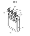
- FIGS. 2 and 3 are perspective schematic views showing an example of a reagent container used in the automatic analyzer of the present invention.
- this reagent container 101 one set is constituted by three containers.
- one set is constituted by a magnetic particle solution and two kinds of reagents.
- Each container includes a main body for storing the reagent, an opening 138 accessible to the reagent, and a lid 102 capable of sealing the opening 138.
- the entire outer shape of the reagent container 101 is a substantially rectangular parallelepiped shape having a shoulder 103, and three openings 138 are arranged above the shoulder and protrude upward.
- a round bar-like projection 126 is provided at one end of the lid 102, and the reagent container 101 is placed on the lid 102. Projects in the lateral direction.
- An RFID tag 141 is attached to the end surface of the reagent container 101.
- the built-in memory of the RFID tag 141 stores a container ID for identifying the reagent container 101, the type of reagent contained in the reagent container 101, the amount of reagent, the expiration date of the reagent, and other necessary information. ing.
- information of the reagent container 101 is obtained using RFID (Radio Frequency IDentification), but not limited to RFID, a bar code or other information reading means may be used.
- FIG. 2 is a schematic perspective view showing a sealed reagent container.
- the opening 138 is sealed by the lid 102.
- a sealing member 139 that can be inserted into the opening 138 and sealed is provided on the lid. If the opening 138 is always open, the internal reagent may evaporate or the concentration of the reagent may change. Also, if the reagent container 101 is accidentally tilted during handling, there is a risk that the reagent in the reagent container 101 will spill. These inconveniences can be reduced by sealing the opening 138 with the lid 102 and opening the lid 102 when necessary.
- FIG. 3 is a schematic perspective view showing the reagent container in an open state.
- the lid 102 is pivoted about the hinge 125 as a rotation axis, so that the lid 102 is opened from the projection 126. At this time, the sealing member 139 is completely removed from the opening 138, and the lid 102 is opened at a large angle around the hinge 125.
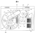
- FIG. 4 is a schematic top view showing an embodiment of the automatic analyzer according to the present invention.
- the automatic analyzer according to the present embodiment stirs a reagent cooler 105 having a reagent loader mechanism 104 that automatically loads and unloads the reagent container 101, and a reagent (particularly, a reagent containing magnetic particles) in the reagent cooler.
- Magnetic particle agitation device 107 magazine 130 for holding a plurality of consumables necessary for analysis (for example, reaction containers and sample dispensing tips), reaction container / sample dispensing for transporting consumables on magazine 130 to an appropriate position With the chip transport device 131 and the sample dispensing chip mounted, the sample dispensing device 132 for dispensing a predetermined amount of sample from the sample container in the sample rack 133 on the transport line to the reaction container, and the reaction container containing the sample.
- a reaction tank 134 held at a predetermined temperature
- a reagent dispensing device 108 that sucks a predetermined amount of reagent in the reagent cooler 105 and discharges it into the reaction container, and the sample and reagent in the reaction container are mixed.
- the reagent cooler 105 is provided with an RFID 143 for reading information of an RFID tag attached to the reagent container in a contactless manner at an access position by the reagent dispensing device 108.
- the reagent cooler 105 is hermetically sealed with a lid (not shown) on the upper surface, but the reagent loader mechanism 104, the stirrer of the magnetic particle stirring device 107, and the probe of the reagent dispensing device 108 are passed through a part of the lid. An opening is provided to allow
- a reagent disk 127 having a plurality of slots in which reagent containers can be installed is provided inside the reagent cool box 105. By rotating the reagent disk 127, any reagent container 101 can be attached to each mechanism. It can be transported to the access position.
- the reagent container moving device 128 can move the reagent container 101 between the reagent loader mechanism 104, the slot of the reagent disk 127, and the stirring position by the magnetic particle stirring device 107.
- the reagent container lid opening / closing device 129 opens the lid of the reagent container 101 at an appropriate timing before processing by the magnetic particle stirring device 107 or the reagent dispensing device 108 and closes after the use of the reagent after the processing is completed. be able to.
- the reagent container 101 used for the analysis is set on the reagent disk 127 in the reagent cold storage 105.
- the operator inserts the reagent container 101 into the reagent loader mechanism 104.
- the reagent loader mechanism 104 is lowered and returned to the reagent cooler 105, and the reagent container 101 mounted on the reagent loader mechanism 104 is moved to the slot of the reagent disk 127 by the reagent container moving device 128.
- the reagent container 101 moved to the reagent disk 127 is used for analysis processing.
- the up and down movement of the reagent loader mechanism 104 may be performed from a screen for operating the automatic analyzer, or a switch may be installed in the vicinity of the reagent loader mechanism 104 and operated by the switch operation. good. Details of the reagent loader mechanism 104 and a method for inserting the reagent container 101 into the reagent loader mechanism 104 will be described later.
- the analysis process is started after the introduction of the reagent container 101 necessary for the analysis is completed.
- the analysis process is automatically executed according to a predetermined procedure under the control of the host computer.
- the reaction vessel / sample dispensing tip transport device 131 transfers the reaction vessel mounted in the magazine 130 into the reaction tank 134, and the sample dispensing tip is further transferred to the probe of the sample dispensing device 132. Transfer to the position to attach to the tip.
- the reaction tank 134 can be driven to rotate horizontally while holding a plurality of reaction containers.
- the reaction tank 134 rotates to the reagent dispensing position, and the reagent in the reagent container 101 is first transferred to the reaction container by the reagent dispensing device 108. Dispensed by the determined amount.
- the host computer communicates with the RFID 143 that has read the information of the RFID tag 141 attached to the reagent container 101 to confirm that the reagent dispensed into the reaction container is a desired reagent.
- the sample dispensing device 132 equipped with the sample dispensing chip aspirates the sample from the sample container mounted on the sample rack 133, and the reaction container into which the reagent is dispensed is rotated to the sample dispensing position by the rotation of the reaction tank 134. The sample is dispensed into the reaction container by the sample dispensing device 132.
- the reaction vessel containing the reagent and the sample is kept warm in the reaction vessel 134 for a certain period of time.
- the reaction container again moves to the reagent dispensing position, and the magnetic particles in the reagent container 101 are dispensed by the reagent dispensing apparatus 108.
- the reaction vessel 134 rotates, the reaction vessel on the reaction vessel 134 is moved to the reaction solution stirring device 135 by the reaction vessel / sample dispensing chip transfer device 131, and the reaction vessel stirring device 135 causes the magnetism in the reaction vessel to move. Agitate the particles and the reagent and specimen reacted for a certain period of time.
- reaction vessel is returned again to the reaction vessel 134 by the reaction vessel / sample dispensing chip transfer device 131 and further reacted for a certain period of time in the reaction vessel 134, and then the reaction solution (reagent / sample / Magnetic particles) are introduced into the detection unit 137, and detection is performed.
- the reaction liquid cleaning device 136 may perform a reaction liquid cleaning process for the purpose of removing impurities contained in the reaction liquid before the detection process. This series of processes can be performed continuously.
- the host computer manages the type, remaining amount, expiration date, and the like of the reagent held by each reagent container in the reagent cooler 105, and displays warnings regarding reagent replenishment and replacement at an appropriate timing.
- the reagent container 101 in which the reagent is accommodated is mounted in the reagent cold storage 105 having the cold keeping function for analysis. Loading / unloading of the reagent container 101 to / from the reagent cooler 105 is performed using a reagent loader mechanism 104 capable of mounting a plurality of sets of reagent containers 101.
- a reagent loader mechanism 104 capable of mounting a plurality of sets of reagent containers 101.
- a plurality of sets of reagent containers 101 are mounted and the reagent disk 127 can be rotated.
- the reagent container 101 can be moved between the reagent loader mechanism 104 and the reagent disk 127.
- a reagent container lid opening / closing device 129 capable of opening and closing the lid 102 of the reagent container 101 in the process is provided.
- a magnetic particle agitation device 107, a reagent dispensing device 108, and the like are provided outside the reagent cooler 105, and these devices are located at an opening provided in a lid that covers the upper part of the reagent cooler 105, and a reagent disk.
- the reagent container 101 mounted on 127 can be accessed.
- the reagent disk 127 can be driven to rotate in the horizontal direction.
- the mounted reagent container 101 is moved to the stirring and dispensing position, and the lid 102 of the reagent container 101 is opened by the reagent container lid opening / closing device 129.
- the magnetic particle stirring device 107 stirs the magnetic particles in the reagent container 101
- the reagent dispensing device 108 dispenses and dispenses the reagent contained in the reagent container 101.
- the lid 102 of the reagent container 101 after the stirring of magnetic particles, reagent dispensing, and dispensing is closed by the reagent container lid opening / closing device 129. Processing and operation by each device in the automatic analyzer are performed under the control of the host computer.
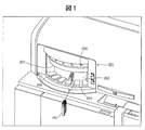
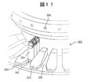
- FIG. 1 is a schematic diagram showing an example of a reagent container loading part of an automatic analyzer.
- the reagent container 101 is carried into the reagent cooler 105 of the automatic analyzer through the reagent container loading unit 201.
- the reagent container loading unit 201 of the present embodiment has an approach region configured by an opening 202 through which the reagent container is introduced into the apparatus, and a space between an upper surface 203 and a lower surface 204 in front of the opening connected to the opening 202.
- the reagent loader mechanism 104 that holds the reagent container 101 and conveys it into the reagent cooler 105 of the automatic analyzer is installed in the apparatus main body inside the opening 202 and does not appear in FIG.
- FIG. 1 shows a state in which the opening 202 is closed by a shielding member provided in the reagent container transport tool of the reagent loader mechanism 104, as will be described later.
- a plurality of guide grooves 205 for guiding the reagent container are radially arranged on the lower surface in front of the opening connected to the opening 202.
- the guide groove 205 is for sliding the lower end portion of the reagent container 101 therein and guiding it toward the inside of the opening 202.
- the five guide grooves are along the insertion direction of the reagent container. Is provided.
- a display lamp 206 for indicating the state is provided at the upper part of the front surface of the reagent container loading part and above each guide groove.
- FIG. 5 to FIG. 7 are schematic cross-sectional views showing the procedure for bringing the reagent container into the automatic analyzer of this embodiment.
- an approach region in front of the opening of the reagent container loading unit, a reagent loader mechanism 104, and a reagent cold storage 105 are shown.
- the procedure for carrying the reagent container into the reagent cooler from the opening of the reagent container loading unit will be described with reference to these drawings.
- FIG. 5 is a schematic cross-sectional view of the automatic analyzer when the reagent container transport tool 210 of the reagent loader mechanism 104 is in the raised position.
- the reagent loader mechanism 104 includes a reagent container transport tool 210 that can move up and down and a lifting mechanism 220 that lifts and lowers the reagent container transport tool.
- the reagent container transporter 210 has a plurality (five in the present embodiment) of slots 211 for inserting reagent containers arranged in a radial pattern, and the cross section is L-shaped above the slot 211.
- the shielding member 212 is provided. The reagent container transport tool 210 can be moved between the raised position shown in FIG. 5 and the lowered position shown in FIG.
- the reagent cooler 105 has an opening 106 for allowing the reagent container transporter 210 to pass therethrough and includes a rotatable reagent disk 127 inside.
- the reagent disk 127 has an annular reagent container placement region on the outer peripheral side.
- An RFID 142 is provided on a side surface of the opening 106.
- the automatic analyzer of the present embodiment has a retreat space in which the shielding member 212 is retreated from the opening of the reagent container insertion unit above the reagent container transporter 210.
- the opening 106 provided in the reagent cooler 105 is not closed by the reagent container transport tool 210 and is opened in this state.
- the guide groove 205 of the reagent container loading unit 201 communicates with the slot 211 of the reagent container transport tool 210. Therefore, the operator can hold the reagent container with one hand, slide it along the guide groove 205 as it is, bring it to the reagent container transport tool 210 of the reagent loader mechanism 104, and insert the reagent container into the slot 211 with certainty.
- the slot 211 of the reagent container transporter 210 is cut out so that a part of the side wall forming the slot does not touch the operator's hand or finger that holds the reagent container and inserts it into the slot.
- the notch 213 is provided at a position corresponding to the position of the operator's hand that holds the reagent container. Therefore, the operator can safely and reliably mount the reagent container in the slot 211 of the reagent container transporting tool 210 without the hand holding the reagent container being obstructed by the wall forming the slot. In other words, the provision of the notch 213 makes it easier for a finger to enter the reagent container transport tool 210, and it is easy to remove the reagent container from the slot when the reagent container is inserted into the slot.
- the reagent container transport tool 210 of the reagent loader mechanism has five slots as the number of the guide grooves 205 provided in the reagent container insertion portion 201 so that the five reagent containers can be held radially.
- the slot width is almost the same as the width of the reagent container and there is not enough room, and the internal viewing state may not be sufficient. It is difficult to insert it quickly and reliably into the slot of the container transporter.
- the guide grooves arranged radially when the plurality of reagent containers are grasped by hand and inserted, the reagent containers do not interfere with each other, and the reagent containers can be prevented from being unexpectedly dropped or spilled.
- the light from the LED 222 held on the substrate 221 provided on the back surface of the reagent container loading unit 201 is guided to the upper surface of the reagent container loading unit 201 by the light guide member 223.
- the light guide member may be omitted by exposing the LED to the upper surface of the reagent container loading unit 201.
- the contact sensor 224 may be provided on the innermost wall where the reagent container 101 of the reagent container insertion slot 211 of the reagent container transporting tool 210 contacts.
- the reagent container transport tool 210 is lowered in that state. Then, the reagent container 101 is sandwiched between adjacent members, and the subsequent processing cannot be performed, or the member is damaged.
- the contact sensor 224 is for dealing with this problem.
- the LED 222 corresponding to the input position that is, the display lamp 206 is turned on to notify the operator.
- the operator can confirm that the reagent container is completely inserted by pushing the reagent container 101 into the slot of the reagent container transport tool 210 until the display lamp 206 is lit.
- FIG. 6 is a schematic cross-sectional view of the automatic analyzer when the reagent container transport tool 210 of the reagent loader mechanism 104 is in the raised position, as in FIG. FIG. 6 shows a state in which the necessary reagent container 101 has been inserted into the reagent container transport tool 210 of the reagent loader mechanism 140. As shown in the figure, the reagent container 101 is fully pushed into the slot of the reagent container transporter 210 and inserted. By providing the guide groove 205 in the reagent container loading unit 201 and the notch 213 in the slot 211, the operator can easily and reliably insert the reagent container 101 into the reagent container transport tool 210 of the reagent loader mechanism 104. It is supposed to be.
- the reagent container transporter 210 is then moved down into the reagent cooler 105 through the opening 106 at the top of the reagent cooler 105 by the lifting mechanism 220.
- the reagent container transport tool 210 moves downward through the opening 106, information on the RFID tag included in the reagent container 101 inserted into the reagent container transport tool 210 is read by the RFID 142.
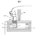
- FIG. 7 is a schematic cross-sectional view of the automatic analyzer when the reagent container transport tool 210 of the reagent loader mechanism 104 is in the lowered position.
- the slot 211 that holds the reagent container of the reagent container transport tool 210 is positioned in the reagent cooler 105.
- the space that can be formed above the shielding member 212 of the reagent container transporter 210 is a retreat space in which the shielding member 212 is retracted from the opening 202 of the reagent container insertion unit.
- the vertical portion of the shielding member 212 provided in the reagent container transporting tool 210 closes the opening 202 of the reagent container inserting unit 201, thereby realizing the inaccessible state shown in FIG.
- the horizontal portion of the shielding member 212 closes the opening 106 at the top of the reagent cooler 105. That is, in the state where the reagent container transport tool 210 of the reagent loader mechanism 104 is at the lowest position, unnecessary access to the inside of the apparatus from the reagent container loading unit 201 is prevented and the cooling efficiency of the reagent cooler 105 is improved.
- the reagent cooler 105 can be sealed.
- the door 202 is provided outside the guide groove 205 to close the opening 202 on the center side of the radial shape as in this embodiment. Since the area for closing the opening is smaller than that for closing 202 and the member can be omitted, it contributes to cost reduction.
- the reagent container 101 inserted in the slot 211 of the reagent container transporter 210 is moved to the reagent disk 127 by the reagent container moving device 128.
- Reagent container moving device 128 can be implemented using known techniques.
- the reagent container moving device 128 shown in FIG. 4 includes a gripping part that sandwiches and grips the reagent container from the side surface, and a telescopic part that moves the gripping part in the radial direction, and includes a reagent container transporting tool of the reagent loader mechanism 104 The reagent container is transferred between the slot 211 of 210 and the slot of the reagent disk 127.
- a procedure reverse to the procedure shown in FIGS. 5 to 7 is executed.
- the reagent container 101 to be discharged is moved to the slot 211 of the reagent container transport tool 210 of the reagent loader mechanism 104 by using the reagent container moving device 128 in the reagent cool box 105.
- the reagent loader mechanism 104 is raised, the operator inserts his / her hand through the opening of the reagent container loading unit 201, grasps the reagent container 101 mounted in the slot 211 of the reagent container transport tool 210 of the reagent loader mechanism 104, and moves it outside the apparatus. Take out.
- the slot of the reagent container placement area on the reagent disk 127 is set on the outer peripheral side of the circular disk, and the reagent container transport tool 210 of the reagent loader mechanism 104 is the reagent disk 127.
- the inside of the reagent container mounting area is lowered. Therefore, the reagent container delivered from the slot of the reagent container transport tool 210 to the reagent disk 127 inside the reagent cooler 105 is moved from the center side to the outer peripheral side along the radial direction of the reagent disk 127.
- the reagent container stored in the reagent cooler from the outside via the reagent container loading part of the automatic analyzer is horizontally inserted into the slot of the reagent container transport tool of the reagent loader mechanism 104 along the radial guide groove.
- Movement (FIG. 5) vertical movement accompanying the lowering of the reagent container transport tool by the lifting mechanism (FIG. 6), horizontal movement transferred from the reagent container transport tool slot of the reagent loader mechanism to the outer peripheral region of the reagent disk
- the reagent is introduced into the reagent cooler by following a U-shaped movement path.
- FIG. 8 and 9 are schematic diagrams showing the relationship between the entire reagent loader mechanism and the guide unit. In order to show the entire reagent loader mechanism, the surrounding structure is removed and shown in a simplified manner.
- FIG. 8 corresponds to FIG. 5 and is a schematic view of a state in which the reagent container transport tool of the reagent loader mechanism is in the raised position.
- FIG. 9 corresponds to FIG. 7 and the reagent container transport tool of the reagent loader mechanism is in the lowered position. It is a schematic diagram of a certain state.
- the reagent container carrier 210 is provided with five slots 211 for inserting reagent containers, the same number as the guide grooves 205.
- the slot 211 for inserting the reagent container of the reagent container transport tool 210 is exposed at the opening 202 of the reagent container loading section 201, The reagent container 101 can be inserted into the slot 211 of the reagent container transporter 210 along the guide groove 205.
- the five guide grooves 205 arranged radially communicate with the five slots of the reagent container transporter 210 also arranged radially.
- the radially arranged slots 211 and the radially arranged guide grooves 205 constitute a radially shaped groove that is completely continuous.
- the side wall forming the slot of the reagent container transporter 210 is cut off on the side facing the operator so that the operator's hand holding the reagent container does not hit. Therefore, an operator who holds the reagent container to be inserted into the slot with one hand puts the bottom of the reagent container into the guide groove 205 and slides the reagent container along the guide groove 205 toward the back of the opening 202 while holding the reagent container.
- the reagent container can be safely and reliably inserted into the slot 211 simply by going on.
- the reagent container charging portion is formed in an arc shape. Accordingly, the arrangement region of the guide groove 205 provided in the reagent container insertion unit 201 and the opening 202 are also arranged in an arc shape, and the surface of the shielding member 212 provided in the reagent container transporter 210 for closing the opening 202 is a cylindrical surface. It has become.
- the shielding member 212 provided on the reagent container transport tool 210 is also lowered from the upper retreat space to the position of the opening 202 of the reagent container loading portion as shown in FIG. Then, the opening 202 is closed. At this time, the shielding member 212 closes the opening of the upper part of the reagent cooler 105 and seals it.
- FIG. 10 is a schematic diagram showing another example of a guide groove provided in the reagent container loading part.
- a plurality of guide grooves 205 for guiding the reagent containers are radially arranged on the lower surface 204 of the approach region provided in front of the opening provided in the reagent container loading unit 201, and the upper surface 203 of the approach region.
- guide grooves 207 facing the guide grooves 205 on the lower surface are arranged radially. Since the reagent container 101 is slid with the upper and lower ends fixed to the upper and lower guide grooves 207 and 205 provided in the approach region, the reagent container 101 can be inserted into the slot of the reagent container transporter 210 with higher accuracy.
- the guide groove 205 provided on the lower surface of the reagent container loading unit 201 has a plurality of convex members 231 arranged on a plane serving as a base, and uses the space between the convex members as a guide groove. It is a form.
- the planar shape of the convex member 231 is a substantially trapezoid.
- FIG. 11 is a schematic diagram showing another example of a guide groove provided in the reagent container loading part.
- the guide groove 205 provided radially on the lower surface 204 of the approach region in front of the opening of the reagent container loading unit 201 has a wide width on the front entrance side, and thereafter has a constant width and a position where the back is higher. It has a shape that is guided up to.
- the guide groove 205 of this embodiment since the width on the front entrance side is wide, it is easy to insert the reagent container 101 into the guide groove 205 for the first time.
- the guide groove 205 of this embodiment is also a form in which a plurality of convex members 232 are arranged on a plane serving as a base, and the space between the convex members is used as a guide groove.
- the planar shape of the convex member 232 is a shape in which the corners on the near side of the trapezoid are chamfered, and the height on the far side is higher than the near side.
- FIG. 12 is a schematic diagram showing another example of a guide groove provided in the reagent container loading part.
- the guide grooves 205 and 207 are provided radially on the upper and lower surfaces of the approach region in front of the opening of the reagent container loading unit 201.
- the guide groove 205 provided on the lower surface of the reagent container insertion portion is a form in which a groove formed by digging down the base plane is used as a guide groove.
- the guide groove 205 is wide on the front side, and has a shape that allows easy insertion when the reagent container 101 is first placed in the guide groove 205.
- the groove is formed so that the depth gradually increases from the plane serving as the base, the portion between the groove and the groove does not collide with the hand during insertion.
- FIG. 13 is a schematic diagram showing another example of a guide groove provided in the reagent container inserting portion.
- guide grooves 205 and 207 are provided radially on the upper and lower surfaces of the approach region in front of the opening of the reagent container loading unit 201.
- an example is shown in which the guide groove 205 starts from the end of the lower surface provided in the reagent container loading unit 201.
- the reagent container transport tool 210 of the reagent loader mechanism 104 may have an apparatus configuration in which less than five or five or more reagent containers can be mounted.
- this invention is not limited to the above-mentioned Example, Various modifications are included.
- the above-described embodiments have been described in detail for easy understanding of the present invention, and are not necessarily limited to those having all the configurations described.
- a part of the configuration of one embodiment can be replaced with the configuration of another embodiment, and the configuration of another embodiment can be added to the configuration of one embodiment.
- Reagent container 104 Reagent loader mechanism 105
- Reagent cooler 127 Reagent disc 201
- Reagent container loading unit 202 Opening 205 Guide groove 206
- Guide groove 210 Reagent container transport tool 211
- Slot 212 Shield member 213 Notch 220 Lifting mechanism 221
Abstract
An automatic analysis device having a structure that makes it possible for an operator to reliably and easily carry out reagent replenishment and replacement is provided with a reagent container input part 201 having an opening 202 for introducing a reagent container 101 into the device, a reagent container transport tool that has a plurality of radially disposed reagent container insertion slots and is capable of moving up and down, a refrigerator that has an opening in the upper part thereof for allowing the reagent container transport tool to pass therethrough and refrigerates a plurality of the reagent containers, and a raising and lowering mechanism for raising and lowering the reagent container transport tool. The reagent container insertion unit has, at the front lower surface of the opening, a plurality of radially disposed guide grooves 205 for guiding the reagent containers, and the guide grooves respectively communicate with the plurality of radially disposed reagent container insertion slots of the reagent container transport tool when the reagent container transport tool is in a raised position.
Description
本発明は、臨床検査における生化学分析や免疫分析等の化学分析に用いる自動分析装置に関する。
The present invention relates to an automatic analyzer used for chemical analysis such as biochemical analysis and immunological analysis in clinical tests.
臨床検査における生化学分析装置や免疫分析装置等の化学分析に用いる自動分析装置は、分析項目に応じて複数種類の試薬を試薬庫内に保持し、使用するタイミングで試薬庫内の試薬容器から所定量の試薬を吸引し、試料と混合し、測定を実行している。試薬庫内に保持されている試薬が分析中に不足した場合、不足した段階で分析を停止して試薬の補充を行うと分析効率が低下する。従って、自動分析装置は、試薬の不足が起こりそうな場合、試薬不足に関する警告を発し、分析中に試薬の補充や交換のために装置の運転を停止しなければならないような状況を防止できるようにされている。特許文献1には、試薬コンテナを内部に取り付けできるようにした装填システムを固定ディスクの一部に設けて、試薬固定ディスクの作動状態に係わらず、試薬コンテナのいずれかを変更できるようにした自動分析装置が記載されている。
Automatic analyzers used for chemical analysis, such as biochemical analyzers and immunoanalyzers in clinical tests, hold multiple types of reagents in the reagent storage according to the analysis items, and from the reagent containers in the reagent storage at the timing of use. A predetermined amount of reagent is aspirated, mixed with the sample, and measurement is performed. When the amount of reagents held in the reagent storage is insufficient during analysis, the analysis efficiency is lowered when the analysis is stopped and the reagent is replenished at the shortage stage. Therefore, the automatic analyzer issues a warning about reagent shortage when a reagent shortage is likely to occur, so that it is possible to prevent a situation in which the operation of the device must be stopped for replenishment or replacement of the reagent during analysis. Has been. In Patent Document 1, an automatic loading system in which a reagent container can be attached inside is provided in a part of a fixed disk so that any of the reagent containers can be changed regardless of the operating state of the reagent fixed disk. An analyzer is described.
交換すべき試薬コンテナを装填システムに取り付ける作業はオペレータによって行われる。特許文献1には、試薬コンテナを装填システムに取り付ける作業を確実かつ容易に行うための装置構造に関しては特に考慮されていない。
* The operator attaches the reagent container to be replaced to the loading system. Patent Document 1 does not particularly consider an apparatus structure for reliably and easily performing an operation of attaching a reagent container to a loading system.
本発明は、オペレータが試薬の補充・交換作業を確実かつ容易に行うことができる構造を有する自動分析装置を提供することを目的とする。
An object of the present invention is to provide an automatic analyzer having a structure that allows an operator to reliably and easily perform a reagent replenishment / replacement operation.
本発明による自動分析装置は、試薬容器を装置内部に導入させる開口を有する試薬容器投入部と、放射状に配置された複数の試薬容器挿入用スロットを有し上下動可能な試薬容器搬送具と、上部に試薬容器搬送具を通過させる開口を有し、複数の試薬容器を保冷する保冷庫と、試薬容器搬送具を昇降させる昇降機構とを有し、試薬容器投入部は開口の前方の下面に試薬容器を案内するための複数のガイド溝が放射状に配置され、放射状に配置された複数のガイド溝は上昇位置にある試薬容器搬送具の放射状に配置された複数のスロットにそれぞれ連通している。
An automatic analyzer according to the present invention includes a reagent container loading part having an opening for introducing a reagent container into the apparatus, a plurality of reagent container insertion slots arranged radially and a vertically movable reagent container transporting tool, The upper part has an opening through which the reagent container transport tool passes, and has a cool box for keeping a plurality of reagent containers cool, and an elevating mechanism for raising and lowering the reagent container transport tool. A plurality of guide grooves for guiding the reagent containers are arranged radially, and the plurality of radially arranged guide grooves communicate with the plurality of radially arranged slots of the reagent container transport tool at the raised position, respectively. .
本発明によると、オペレータによる試薬の補充・交換作業を確実かつ容易に行うことが可能となる。
上記した以外の、課題、構成及び効果は、以下の実施形態の説明により明らかにされる。 According to the present invention, it is possible to reliably and easily perform reagent replenishment / exchange work by an operator.
Problems, configurations, and effects other than those described above will be clarified by the following description of embodiments.
以下、図面を参照して本発明の実施の形態を説明する。ここでは、試料の分析に磁性粒子試薬を用いる自動分析装置を例に挙げて説明するが、試薬の種類等に特に限定はない。
Hereinafter, embodiments of the present invention will be described with reference to the drawings. Here, an automatic analyzer using a magnetic particle reagent for sample analysis will be described as an example, but the type of reagent is not particularly limited.
図2、図3は、本発明の自動分析装置で使用する試薬容器の一例を示す斜視模式図である。この試薬容器101は、3本の容器で1セットを構成しており、例えば磁性粒子溶液と2種類の試薬で1セットを構成している。各容器は、試薬を収容する本体部と、試薬に対してアクセス可能な開口部138と、開口部138を密閉可能な蓋部102からなっている。試薬容器101全体の外形は、肩部103を有する略直方体の形状であり、肩部の上側に3つの開口部138が並んで上側に突出している。自動分析装置に組み込まれた試薬容器蓋開閉装置による開閉動作を可能とするため、蓋部102の一端には丸棒状の突起部126が設けられており、蓋部102に対して試薬容器101の側面方向に突出している。また、試薬容器101の端面にはRFIDタグ141が取り付けられている。RFIDタグ141の内蔵メモリには、当該試薬容器101を特定するための容器ID、その試薬容器101に収容されている試薬の種類、試薬の量、試薬の有効期限、その他必要な情報が格納されている。なお、本実施例ではRFID(Radio Frequency IDentification)を用いて試薬容器101の情報を取得するようにしたが、RFIDに限らずバーコードその他の情報読み取り手段を用いても構わない。
2 and 3 are perspective schematic views showing an example of a reagent container used in the automatic analyzer of the present invention. In this reagent container 101, one set is constituted by three containers. For example, one set is constituted by a magnetic particle solution and two kinds of reagents. Each container includes a main body for storing the reagent, an opening 138 accessible to the reagent, and a lid 102 capable of sealing the opening 138. The entire outer shape of the reagent container 101 is a substantially rectangular parallelepiped shape having a shoulder 103, and three openings 138 are arranged above the shoulder and protrude upward. In order to enable an opening / closing operation by a reagent container lid opening / closing device incorporated in the automatic analyzer, a round bar-like projection 126 is provided at one end of the lid 102, and the reagent container 101 is placed on the lid 102. Projects in the lateral direction. An RFID tag 141 is attached to the end surface of the reagent container 101. The built-in memory of the RFID tag 141 stores a container ID for identifying the reagent container 101, the type of reagent contained in the reagent container 101, the amount of reagent, the expiration date of the reagent, and other necessary information. ing. In the present embodiment, information of the reagent container 101 is obtained using RFID (Radio Frequency IDentification), but not limited to RFID, a bar code or other information reading means may be used.
図2は、密閉状態の試薬容器を示す斜視模式図である。初期状態では開口部138は蓋部102によって密閉されている。なお、開口部138を確実に密閉するため、蓋部には開口部138内に挿入して密閉することが可能な密閉部材139が設けられている。開口部138が常時開放されていると、内部の試薬が蒸発したり、試薬に濃度変化が生じたりする恐れがある。また、取り扱いの際に誤って試薬容器101を倒したりした場合に、試薬容器101内の試薬がこぼれる危険がある。開口部138を蓋部102によって密閉しておき、必要な時に蓋部102を開くことにより、これらの不都合を軽減することができる。図3は、開放状態の試薬容器を示す斜視模式図である。蓋部102はヒンジ125を回転軸として回動することにより突起部126の方から蓋部102が開く。このとき、密閉部材139は完全に開口部138から取り除かれており、蓋部102はヒンジ125を中心として大きな角度で開放されている。
FIG. 2 is a schematic perspective view showing a sealed reagent container. In the initial state, the opening 138 is sealed by the lid 102. In order to securely seal the opening 138, a sealing member 139 that can be inserted into the opening 138 and sealed is provided on the lid. If the opening 138 is always open, the internal reagent may evaporate or the concentration of the reagent may change. Also, if the reagent container 101 is accidentally tilted during handling, there is a risk that the reagent in the reagent container 101 will spill. These inconveniences can be reduced by sealing the opening 138 with the lid 102 and opening the lid 102 when necessary. FIG. 3 is a schematic perspective view showing the reagent container in an open state. The lid 102 is pivoted about the hinge 125 as a rotation axis, so that the lid 102 is opened from the projection 126. At this time, the sealing member 139 is completely removed from the opening 138, and the lid 102 is opened at a large angle around the hinge 125.
図4は、本発明による自動分析装置の実施例を示す上面概略図である。本実施例の自動分析装置は、試薬容器101を自動的に内部に搬入・搬出する試薬ローダ機構104を備えた試薬保冷庫105、試薬保冷庫内の試薬(特に磁性粒子を含む試薬)を攪拌する磁性粒子撹拌装置107、分析に必要な消耗品(例えば反応容器や検体分注チップなど)を複数保持するマガジン130、マガジン130上の消耗品を適切な位置に搬送する反応容器/検体分注チップ搬送装置131、検体分注チップを装着した状態で、搬送ライン上の検体ラック133の検体容器から所定量の検体を反応容器に分注する検体分注装置132、検体を収容した反応容器を所定の温度で保持する反応槽134、試薬保冷庫105内の試薬を所定量吸引して反応容器内に吐出する試薬分注装置108、反応容器中の検体と試薬を混合するために攪拌する反応液撹拌装置135、反応容器中の測定対象成分以外の成分を除去する反応液洗浄装置136、反応液中の測定対象成分を定量測定するための検出部137を備える。試薬保冷庫105には、試薬分注装置108によるアクセス位置に試薬容器に取り付けられたRFIDタグの情報を非接触で読み取るためのRFID143が設けられている。
FIG. 4 is a schematic top view showing an embodiment of the automatic analyzer according to the present invention. The automatic analyzer according to the present embodiment stirs a reagent cooler 105 having a reagent loader mechanism 104 that automatically loads and unloads the reagent container 101, and a reagent (particularly, a reagent containing magnetic particles) in the reagent cooler. Magnetic particle agitation device 107, magazine 130 for holding a plurality of consumables necessary for analysis (for example, reaction containers and sample dispensing tips), reaction container / sample dispensing for transporting consumables on magazine 130 to an appropriate position With the chip transport device 131 and the sample dispensing chip mounted, the sample dispensing device 132 for dispensing a predetermined amount of sample from the sample container in the sample rack 133 on the transport line to the reaction container, and the reaction container containing the sample. A reaction tank 134 held at a predetermined temperature, a reagent dispensing device 108 that sucks a predetermined amount of reagent in the reagent cooler 105 and discharges it into the reaction container, and the sample and reagent in the reaction container are mixed. Comprising a detection section 137 for quantitatively measuring reaction stirring device 135 for stirring, the reaction liquid cleaning device 136 to remove components other than the measurement target component in the reaction vessel, the measurement target component in the reaction solution. The reagent cooler 105 is provided with an RFID 143 for reading information of an RFID tag attached to the reagent container in a contactless manner at an access position by the reagent dispensing device 108.
試薬保冷庫105は上面を蓋(図示しない)により密閉されているが、蓋の一部には試薬ローダ機構104、磁性粒子攪拌装置107の攪拌子、試薬分注装置108のプローブを通過させることができる開口が設けられている。また、試薬保冷庫105内部には試薬容器を設置することができるスロットを複数備えた試薬ディスク127が設けられており、試薬ディスク127を回転移動させることにより、任意の試薬容器101を各機構のアクセス位置に搬送することができる。試薬容器移動装置128は、試薬ローダ機構104と試薬ディスク127のスロット、磁性粒子攪拌装置107による攪拌位置との間で、試薬容器101を移動させることができる。また、試薬容器蓋開閉装置129は、磁性粒子攪拌装置107あるいは試薬分注装置108によって処理する前に適切なタイミングで試薬容器101の蓋を開放し、処理が終了した後には試薬の使用後に閉じることができる。
The reagent cooler 105 is hermetically sealed with a lid (not shown) on the upper surface, but the reagent loader mechanism 104, the stirrer of the magnetic particle stirring device 107, and the probe of the reagent dispensing device 108 are passed through a part of the lid. An opening is provided to allow In addition, a reagent disk 127 having a plurality of slots in which reagent containers can be installed is provided inside the reagent cool box 105. By rotating the reagent disk 127, any reagent container 101 can be attached to each mechanism. It can be transported to the access position. The reagent container moving device 128 can move the reagent container 101 between the reagent loader mechanism 104, the slot of the reagent disk 127, and the stirring position by the magnetic particle stirring device 107. The reagent container lid opening / closing device 129 opens the lid of the reagent container 101 at an appropriate timing before processing by the magnetic particle stirring device 107 or the reagent dispensing device 108 and closes after the use of the reagent after the processing is completed. be able to.
分析開始前の準備として、最初に、分析に使用する試薬容器101を試薬保冷庫105内の試薬ディスク127に設置する。オペレータは、試薬容器101を試薬ローダ機構104に挿入する。その後、試薬ローダ機構104を下降させて試薬保冷庫105内へ戻し、試薬ローダ機構104に載っている試薬容器101を、試薬容器移動装置128により試薬ディスク127のスロットへ移動させる。試薬ディスク127へ移動された試薬容器101が分析処理に使用される。試薬ローダ機構104の上下動作は、自動分析装置を操作するための画面から実施できるようにしても良いし、試薬ローダ機構104の近傍にスイッチを設置し、そのスイッチ操作で実施できるようにしても良い。試薬ローダ機構104の詳細及び試薬ローダ機構104への試薬容器101の挿入方法については後述する。
As preparation before starting the analysis, first, the reagent container 101 used for the analysis is set on the reagent disk 127 in the reagent cold storage 105. The operator inserts the reagent container 101 into the reagent loader mechanism 104. Thereafter, the reagent loader mechanism 104 is lowered and returned to the reagent cooler 105, and the reagent container 101 mounted on the reagent loader mechanism 104 is moved to the slot of the reagent disk 127 by the reagent container moving device 128. The reagent container 101 moved to the reagent disk 127 is used for analysis processing. The up and down movement of the reagent loader mechanism 104 may be performed from a screen for operating the automatic analyzer, or a switch may be installed in the vicinity of the reagent loader mechanism 104 and operated by the switch operation. good. Details of the reagent loader mechanism 104 and a method for inserting the reagent container 101 into the reagent loader mechanism 104 will be described later.
分析に必要な試薬容器101の投入が完了後、分析処理が開始される。分析処理はホストコンピュータの制御下に、予め定められた手順に従って自動的に実行される。一例を示すと、まず反応容器/検体分注チップ搬送装置131により、マガジン130に搭載されている反応容器を反応槽134内に移送し、さらに検体分注チップを検体分注装置132のプローブの先端に装着させる位置まで移送する。反応槽134は複数の反応容器を保持した状態で水平回転駆動することができ、反応槽134が試薬分注位置まで回転し、まず試薬分注装置108によって試薬容器101内の試薬が反応容器に決められた量だけ分注される。このとき、ホストコンピュータは、試薬容器101に取り付けられたRFIDタグ141の情報を読み取ったRFID143と通信して、反応容器に分注される試薬が所望の試薬であることを確認する。同時に、検体分注チップを装着した検体分注装置132が検体ラック133に搭載された検体容器から検体を吸引し、試薬が分注された反応容器を反応槽134の回転により検体分注位置まで移動させ、検体分注装置132により反応容器内に検体が分注される。その後、試薬と検体を反応容器内で反応させるために、試薬と検体が入った反応容器は反応槽134上で一定時間保温される。その後、再び反応容器は試薬分注位置まで移動して、試薬分注装置108により試薬容器101内の磁性粒子が分注される。そして、反応槽134が回転した後、反応容器/検体分注チップ搬送装置131により反応槽134上の反応容器を反応液撹拌装置135へ移動させて、反応液撹拌装置135により反応容器内の磁性粒子及び一定時間反応させた試薬及び検体を撹拌する。撹拌終了した反応容器は再び反応容器/検体分注チップ搬送装置131により反応槽134へ戻され、さらに反応槽134上で一定時間反応させられた後、反応容器内の反応液(試薬/検体/磁性粒子)が検出部137内へ導入され、検出が行われる。ここで、分析項目によっては、検出処理の前に、反応液洗浄装置136にて、反応液に含まれる不純物を除去する目的で、反応液の洗浄処理を行うこともある。この一連の処理を、連続して実施することが可能である。ホストコンピュータは、試薬保冷庫105内の各試薬容器が保持している試薬の種類、残量、有効期限等を管理し、適切なタイミングで試薬の補充、交換に関する警告を表示する。
The analysis process is started after the introduction of the reagent container 101 necessary for the analysis is completed. The analysis process is automatically executed according to a predetermined procedure under the control of the host computer. As an example, first, the reaction vessel / sample dispensing tip transport device 131 transfers the reaction vessel mounted in the magazine 130 into the reaction tank 134, and the sample dispensing tip is further transferred to the probe of the sample dispensing device 132. Transfer to the position to attach to the tip. The reaction tank 134 can be driven to rotate horizontally while holding a plurality of reaction containers. The reaction tank 134 rotates to the reagent dispensing position, and the reagent in the reagent container 101 is first transferred to the reaction container by the reagent dispensing device 108. Dispensed by the determined amount. At this time, the host computer communicates with the RFID 143 that has read the information of the RFID tag 141 attached to the reagent container 101 to confirm that the reagent dispensed into the reaction container is a desired reagent. At the same time, the sample dispensing device 132 equipped with the sample dispensing chip aspirates the sample from the sample container mounted on the sample rack 133, and the reaction container into which the reagent is dispensed is rotated to the sample dispensing position by the rotation of the reaction tank 134. The sample is dispensed into the reaction container by the sample dispensing device 132. Thereafter, in order to cause the reagent and the sample to react in the reaction vessel, the reaction vessel containing the reagent and the sample is kept warm in the reaction vessel 134 for a certain period of time. Thereafter, the reaction container again moves to the reagent dispensing position, and the magnetic particles in the reagent container 101 are dispensed by the reagent dispensing apparatus 108. Then, after the reaction vessel 134 rotates, the reaction vessel on the reaction vessel 134 is moved to the reaction solution stirring device 135 by the reaction vessel / sample dispensing chip transfer device 131, and the reaction vessel stirring device 135 causes the magnetism in the reaction vessel to move. Agitate the particles and the reagent and specimen reacted for a certain period of time. After the stirring, the reaction vessel is returned again to the reaction vessel 134 by the reaction vessel / sample dispensing chip transfer device 131 and further reacted for a certain period of time in the reaction vessel 134, and then the reaction solution (reagent / sample / Magnetic particles) are introduced into the detection unit 137, and detection is performed. Here, depending on the analysis item, the reaction liquid cleaning device 136 may perform a reaction liquid cleaning process for the purpose of removing impurities contained in the reaction liquid before the detection process. This series of processes can be performed continuously. The host computer manages the type, remaining amount, expiration date, and the like of the reagent held by each reagent container in the reagent cooler 105, and displays warnings regarding reagent replenishment and replacement at an appropriate timing.
本実施例の自動分析装置では、保冷機能を有する試薬保冷庫105内へ試薬の収容された試薬容器101を搭載して分析を行う。試薬保冷庫105への試薬容器101の搬入・搬出は試薬容器101を複数組搭載可能な試薬ローダ機構104を用いて行われる。試薬保冷庫105内には、試薬容器101を複数組搭載して回転可能な試薬ディスク127、試薬容器101を試薬ローダ機構104と試薬ディスク127との間で移動可能な試薬容器移動装置128、分析過程の中で試薬容器101の蓋部102を開閉可能な試薬容器蓋開閉装置129などを備えている。試薬保冷庫105の外部には、磁性粒子撹拌装置107や試薬分注装置108などを備えており、それらの装置は試薬保冷庫105の上部を覆う蓋に設けられた開口の位置で、試薬ディスク127に搭載された試薬容器101内へアクセスできる。
In the automatic analyzer according to the present embodiment, the reagent container 101 in which the reagent is accommodated is mounted in the reagent cold storage 105 having the cold keeping function for analysis. Loading / unloading of the reagent container 101 to / from the reagent cooler 105 is performed using a reagent loader mechanism 104 capable of mounting a plurality of sets of reagent containers 101. In the reagent cooler 105, a plurality of sets of reagent containers 101 are mounted and the reagent disk 127 can be rotated. The reagent container 101 can be moved between the reagent loader mechanism 104 and the reagent disk 127. A reagent container lid opening / closing device 129 capable of opening and closing the lid 102 of the reagent container 101 in the process is provided. A magnetic particle agitation device 107, a reagent dispensing device 108, and the like are provided outside the reagent cooler 105, and these devices are located at an opening provided in a lid that covers the upper part of the reagent cooler 105, and a reagent disk. The reagent container 101 mounted on 127 can be accessed.
試薬ディスク127は、水平方向に回転駆動可能であり、分析過程においては、搭載された試薬容器101を撹拌分注位置まで移動させ、試薬容器蓋開閉装置129により試薬容器101の蓋部102を開けて、磁性粒子撹拌装置107で試薬容器101内の磁性粒子の撹拌、試薬分注装置108にて試薬容器101に収容された試薬の分取、分注を行う。磁性粒子の撹拌及び試薬の分取、分注の終了した試薬容器101の蓋部102は、試薬容器蓋開閉装置129により閉められる。自動分析装置内の各装置による処理、操作はホストコンピュータの制御の下に行われる。
The reagent disk 127 can be driven to rotate in the horizontal direction. In the analysis process, the mounted reagent container 101 is moved to the stirring and dispensing position, and the lid 102 of the reagent container 101 is opened by the reagent container lid opening / closing device 129. Then, the magnetic particle stirring device 107 stirs the magnetic particles in the reagent container 101, and the reagent dispensing device 108 dispenses and dispenses the reagent contained in the reagent container 101. The lid 102 of the reagent container 101 after the stirring of magnetic particles, reagent dispensing, and dispensing is closed by the reagent container lid opening / closing device 129. Processing and operation by each device in the automatic analyzer are performed under the control of the host computer.
図1は、自動分析装置の試薬容器投入部の一例を示す模式図である。試薬容器101は試薬容器投入部201を通して自動分析装置の試薬保冷庫105に搬入される。
FIG. 1 is a schematic diagram showing an example of a reagent container loading part of an automatic analyzer. The reagent container 101 is carried into the reagent cooler 105 of the automatic analyzer through the reagent container loading unit 201.
本実施例の試薬容器投入部201は、試薬容器を装置内部に導入させる開口202と、開口202につながる開口前方の上面203と下面204の間の空間で構成されるアプローチ領域を有する。試薬容器101を保持して自動分析装置の試薬保冷庫105内に搬送する試薬ローダ機構104は開口202より内側の装置本体内に設置されており、図1には現れていない。図1は、後述するように、試薬ローダ機構104の試薬容器搬送具が備える遮蔽部材によって開口202が塞がれた状態を示している。本実施例では、開口202につながる開口前方の下面に試薬容器を案内するための複数のガイド溝205が放射状に配置されている。ガイド溝205は、試薬容器101の下端部をその中でスライドさせて開口202の内部に向けて案内するためのものであり、本例では5本のガイド溝が試薬容器の挿入方向に沿って設けられている。試薬容器投入部の前面上部で各ガイド溝の上方には、状態を示す表示ランプ206が設けられている。
The reagent container loading unit 201 of the present embodiment has an approach region configured by an opening 202 through which the reagent container is introduced into the apparatus, and a space between an upper surface 203 and a lower surface 204 in front of the opening connected to the opening 202. The reagent loader mechanism 104 that holds the reagent container 101 and conveys it into the reagent cooler 105 of the automatic analyzer is installed in the apparatus main body inside the opening 202 and does not appear in FIG. FIG. 1 shows a state in which the opening 202 is closed by a shielding member provided in the reagent container transport tool of the reagent loader mechanism 104, as will be described later. In this embodiment, a plurality of guide grooves 205 for guiding the reagent container are radially arranged on the lower surface in front of the opening connected to the opening 202. The guide groove 205 is for sliding the lower end portion of the reagent container 101 therein and guiding it toward the inside of the opening 202. In this example, the five guide grooves are along the insertion direction of the reagent container. Is provided. A display lamp 206 for indicating the state is provided at the upper part of the front surface of the reagent container loading part and above each guide groove.
図5から図7は、本実施例の自動分析装置への試薬容器搬入の手順を示す断面模式図である。図には、試薬容器投入部の開口の前方のアプローチ領域、試薬ローダ機構104及び試薬保冷庫105が示されている。これらの図を用いて、試薬容器を試薬容器投入部の開口から試薬保冷庫に搬入する手順を説明する。
FIG. 5 to FIG. 7 are schematic cross-sectional views showing the procedure for bringing the reagent container into the automatic analyzer of this embodiment. In the figure, an approach region in front of the opening of the reagent container loading unit, a reagent loader mechanism 104, and a reagent cold storage 105 are shown. The procedure for carrying the reagent container into the reagent cooler from the opening of the reagent container loading unit will be described with reference to these drawings.
図5は、試薬ローダ機構104の試薬容器搬送具210が上昇位置にあるときの自動分析装置の断面模式図である。試薬ローダ機構104は、上下動可能な試薬容器搬送具210と試薬容器搬送具を昇降させる昇降機構220を有する。試薬容器搬送具210は、図8に示すように、放射状に配置された複数(本実施例では5個)の試薬容器挿入用のスロット211を有し、スロット211の上部に断面がL字状の遮蔽部材212を備える。試薬容器搬送具210は、昇降機構220によって図5に示した上昇位置と図7に示した下降位置の間を移動可能になっている。試薬保冷庫105は、上部に試薬容器搬送具210を通過させる開口106を有し、内部に回転可能な試薬ディスク127を備える。試薬ディスク127は、外周側に円環状の試薬容器載置領域を有する。開口106の側面にはRFID142が設けられている。
FIG. 5 is a schematic cross-sectional view of the automatic analyzer when the reagent container transport tool 210 of the reagent loader mechanism 104 is in the raised position. The reagent loader mechanism 104 includes a reagent container transport tool 210 that can move up and down and a lifting mechanism 220 that lifts and lowers the reagent container transport tool. As shown in FIG. 8, the reagent container transporter 210 has a plurality (five in the present embodiment) of slots 211 for inserting reagent containers arranged in a radial pattern, and the cross section is L-shaped above the slot 211. The shielding member 212 is provided. The reagent container transport tool 210 can be moved between the raised position shown in FIG. 5 and the lowered position shown in FIG. The reagent cooler 105 has an opening 106 for allowing the reagent container transporter 210 to pass therethrough and includes a rotatable reagent disk 127 inside. The reagent disk 127 has an annular reagent container placement region on the outer peripheral side. An RFID 142 is provided on a side surface of the opening 106.
試薬容器搬送具210を上昇させたことにより、スロット211の上部に設けられた遮蔽部材212が試薬容器投入部201の開口202の上方に移動して開口202を開放する。換言すると、本実施例の自動分析装置は、試薬容器搬送具210の上方に遮蔽部材212を試薬容器投入部の開口から退避させる退避空間を有する。一方、試薬保冷庫105に設けられた開口106は、この状態では試薬容器搬送具210によっては塞がれておらず開放されている。昇降機構220によって試薬容器搬送具210を上昇させた状態で、試薬容器投入部201のガイド溝205は試薬容器搬送具210のスロット211まで連通している。従って、オペレータは試薬容器を片手で把持しそのままガイド溝205に沿ってスライドさせて試薬ローダ機構104の試薬容器搬送具210にまで持ち込み、その試薬容器をスロット211に確実に挿入することができる。試薬容器搬送具210のスロット211は、スロットを形成する側壁の一部が試薬容器を把持してスロットに挿入するオペレータの手や指が触れないように切欠かれている。この切欠き213は試薬容器を掴んだオペレータの手の位置に対応する個所に設けられている。従って、オペレータは試薬容器を掴んだ手がスロットを形作る壁に邪魔されることなく、試薬容器を安全かつ確実に試薬容器搬送具210のスロット211に装着することができる。すなわち、切欠き213を設けたことにより試薬容器搬送具210に指が入りやすくなり、スロットへの試薬容器挿入時あるいはスロットからの試薬容器取り出しが容易になる。
When the reagent container transport tool 210 is raised, the shielding member 212 provided at the upper portion of the slot 211 moves above the opening 202 of the reagent container loading unit 201 to open the opening 202. In other words, the automatic analyzer of the present embodiment has a retreat space in which the shielding member 212 is retreated from the opening of the reagent container insertion unit above the reagent container transporter 210. On the other hand, the opening 106 provided in the reagent cooler 105 is not closed by the reagent container transport tool 210 and is opened in this state. With the reagent container transport tool 210 raised by the elevating mechanism 220, the guide groove 205 of the reagent container loading unit 201 communicates with the slot 211 of the reagent container transport tool 210. Therefore, the operator can hold the reagent container with one hand, slide it along the guide groove 205 as it is, bring it to the reagent container transport tool 210 of the reagent loader mechanism 104, and insert the reagent container into the slot 211 with certainty. The slot 211 of the reagent container transporter 210 is cut out so that a part of the side wall forming the slot does not touch the operator's hand or finger that holds the reagent container and inserts it into the slot. The notch 213 is provided at a position corresponding to the position of the operator's hand that holds the reagent container. Therefore, the operator can safely and reliably mount the reagent container in the slot 211 of the reagent container transporting tool 210 without the hand holding the reagent container being obstructed by the wall forming the slot. In other words, the provision of the notch 213 makes it easier for a finger to enter the reagent container transport tool 210, and it is easy to remove the reagent container from the slot when the reagent container is inserted into the slot.
本実施例では、試薬ローダ機構の試薬容器搬送具210は試薬容器投入部201に設けられたガイド溝205の数と同じく5個のスロットを有し、5個の試薬容器を放射状に保持できるようになっているが、スロットの幅はほぼ試薬容器の幅と同じで余裕がなく、また内部の視認状態が十分ではない場合もあるため、試薬容器投入部にガイド溝が無いと試薬容器を試薬容器搬送具のスロットに迅速かつ確実に挿入するのは困難である。また、放射状に配置されたガイド溝を有することで、複数の試薬容器を手で掴んで挿入する際に互いに干渉せず、試薬容器の不意な落下やこぼれを防止することができる。
In the present embodiment, the reagent container transport tool 210 of the reagent loader mechanism has five slots as the number of the guide grooves 205 provided in the reagent container insertion portion 201 so that the five reagent containers can be held radially. However, the slot width is almost the same as the width of the reagent container and there is not enough room, and the internal viewing state may not be sufficient. It is difficult to insert it quickly and reliably into the slot of the container transporter. In addition, by having the guide grooves arranged radially, when the plurality of reagent containers are grasped by hand and inserted, the reagent containers do not interfere with each other, and the reagent containers can be prevented from being unexpectedly dropped or spilled.
なお、本実施例では、試薬容器投入部201の裏面に設けられた基板221に保持されているLED222からの光を導光部材223によって試薬容器投入部201の上部表面に導くことで表示ランプ206を構成しているが、勿論、LEDを試薬容器投入部201の上部表面に露出させることで導光部材を省略してもよい。このように、試薬容器搬送具210が上昇位置にあるとき、基板221が遮蔽部材212と対向する配置とすることで、基板221からの発熱が遮蔽部材212によって狭い空間に閉じ込められ、密閉状態にない試薬保冷庫105に悪影響を与えることがない。
In the present embodiment, the light from the LED 222 held on the substrate 221 provided on the back surface of the reagent container loading unit 201 is guided to the upper surface of the reagent container loading unit 201 by the light guide member 223. Of course, the light guide member may be omitted by exposing the LED to the upper surface of the reagent container loading unit 201. As described above, when the reagent container transporter 210 is in the raised position, the substrate 221 is disposed so as to face the shielding member 212, so that the heat generated from the substrate 221 is confined in a narrow space by the shielding member 212, and the sealed state is achieved. There is no adverse effect on the reagent refrigerating machine 105 that is not present.
試薬容器搬送具210の試薬容器挿入用のスロット211の試薬容器101が接する最奥の壁に接触センサ224を備えてもよい。オペレータが試薬容器搬送具210のスロット211に試薬容器101を挿入するとき完全に挿入せずに中途半端な状態で放置することがあると、その状態のまま試薬容器搬送具210を下降させてしまうと、試薬容器101を近傍の部材で挟み込んでしまい、その後の処理が進められなくなる、あるいは部材が破損するという問題が発生する。接触センサ224はこの問題に対処するためのものである。スロット211に挿入した試薬容器101が接触センサ224と接触することで、投入した位置に対応するLED222すなわち表示ランプ206を点灯させてオペレータに知らせる。オペレータは、表示ランプ206が点灯するまで試薬容器101を試薬容器搬送具210のスロットに押し込むことで試薬容器が完全に挿入されたことを確認できる。
The contact sensor 224 may be provided on the innermost wall where the reagent container 101 of the reagent container insertion slot 211 of the reagent container transporting tool 210 contacts. When the operator inserts the reagent container 101 into the slot 211 of the reagent container transport tool 210 and leaves it in a halfway state without completely inserting it, the reagent container transport tool 210 is lowered in that state. Then, the reagent container 101 is sandwiched between adjacent members, and the subsequent processing cannot be performed, or the member is damaged. The contact sensor 224 is for dealing with this problem. When the reagent container 101 inserted into the slot 211 comes into contact with the contact sensor 224, the LED 222 corresponding to the input position, that is, the display lamp 206 is turned on to notify the operator. The operator can confirm that the reagent container is completely inserted by pushing the reagent container 101 into the slot of the reagent container transport tool 210 until the display lamp 206 is lit.
図6は、図5と同じく試薬ローダ機構104の試薬容器搬送具210が上昇位置にあるときの自動分析装置の断面模式図である。図6は、試薬ローダ機構140の試薬容器搬送具210に必要な試薬容器101の挿入が完了した状態を示している。図示のように、試薬容器101は試薬容器搬送具210のスロットに最後まで完全に押し込まれて挿入されている。試薬容器投入部201にガイド溝205を設けたこと及びスロット211に切り欠き213を設けたことにより、オペレータによる試薬ローダ機構104の試薬容器搬送具210への試薬容器101の挿入操作を容易かつ確実なものとしている。試薬容器搬送具210は、次に昇降機構220によって試薬保冷庫105の上部の開口106を通して試薬保冷庫105内に下降移動される。試薬容器搬送具210が開口106を通って下降移動する過程で、試薬容器搬送具210に挿入された試薬容器101が備えるRFIDタグの情報がRFID142によって読み取られる。
FIG. 6 is a schematic cross-sectional view of the automatic analyzer when the reagent container transport tool 210 of the reagent loader mechanism 104 is in the raised position, as in FIG. FIG. 6 shows a state in which the necessary reagent container 101 has been inserted into the reagent container transport tool 210 of the reagent loader mechanism 140. As shown in the figure, the reagent container 101 is fully pushed into the slot of the reagent container transporter 210 and inserted. By providing the guide groove 205 in the reagent container loading unit 201 and the notch 213 in the slot 211, the operator can easily and reliably insert the reagent container 101 into the reagent container transport tool 210 of the reagent loader mechanism 104. It is supposed to be. The reagent container transporter 210 is then moved down into the reagent cooler 105 through the opening 106 at the top of the reagent cooler 105 by the lifting mechanism 220. In the process in which the reagent container transport tool 210 moves downward through the opening 106, information on the RFID tag included in the reagent container 101 inserted into the reagent container transport tool 210 is read by the RFID 142.
図7は、試薬ローダ機構104の試薬容器搬送具210が下降位置にあるときの自動分析装置の断面模式図である。昇降機構220によって試薬容器搬送具210が下降位置に移動されると、試薬容器搬送具210の試薬容器を保持しているスロット211は試薬保冷庫105内に位置する。この状態で試薬容器搬送具210の遮蔽部材212の上方にできる空間は、遮蔽部材212を試薬容器投入部の開口202から退避させる退避空間である。このとき、試薬容器搬送具210が備える遮蔽部材212の垂直部分は試薬容器投入部201の開口202を塞ぎ、図1に示したアクセス不能状態を実現する。また、試薬容器搬送具210が下降位置にあるとき、遮蔽部材212の水平部分は試薬保冷庫105の上部の開口106を塞ぐ。つまり、試薬ローダ機構104の試薬容器搬送具210が最も下方位置にある状態では、試薬容器投入部201からの装置内への無用のアクセスを防止すると共に、試薬保冷庫105の保冷効率向上、ゴミや埃の混入防止のため、試薬保冷庫105を密閉できる構造となっている。なお、試薬容器投入部201にガイド溝205が放射状に設けられているため、本実施例のように放射形状の中心側で開口202を塞ぐ方が、ガイド溝205の外側に扉を設けて開口202を塞ぐよりも開口を塞ぐ面積が小さく、部材を省略できるので低コスト化に寄与する。
FIG. 7 is a schematic cross-sectional view of the automatic analyzer when the reagent container transport tool 210 of the reagent loader mechanism 104 is in the lowered position. When the reagent container transport tool 210 is moved to the lowered position by the elevating mechanism 220, the slot 211 that holds the reagent container of the reagent container transport tool 210 is positioned in the reagent cooler 105. In this state, the space that can be formed above the shielding member 212 of the reagent container transporter 210 is a retreat space in which the shielding member 212 is retracted from the opening 202 of the reagent container insertion unit. At this time, the vertical portion of the shielding member 212 provided in the reagent container transporting tool 210 closes the opening 202 of the reagent container inserting unit 201, thereby realizing the inaccessible state shown in FIG. In addition, when the reagent container transport tool 210 is in the lowered position, the horizontal portion of the shielding member 212 closes the opening 106 at the top of the reagent cooler 105. That is, in the state where the reagent container transport tool 210 of the reagent loader mechanism 104 is at the lowest position, unnecessary access to the inside of the apparatus from the reagent container loading unit 201 is prevented and the cooling efficiency of the reagent cooler 105 is improved. In order to prevent mixing of dust and dust, the reagent cooler 105 can be sealed. In addition, since the guide groove 205 is provided radially in the reagent container loading unit 201, the door 202 is provided outside the guide groove 205 to close the opening 202 on the center side of the radial shape as in this embodiment. Since the area for closing the opening is smaller than that for closing 202 and the member can be omitted, it contributes to cost reduction.
その後、試薬容器搬送具210のスロット211に挿入されている試薬容器101を試薬容器移動装置128にて、試薬ディスク127へ移動させる。試薬容器移動装置128は既知の技術を使って実現することができる。一例として、図4に示した試薬容器移動装置128は、試薬容器を側面から挟み込んで把持する把持部と把持部を動径方向に移動させる伸縮部を備え、試薬ローダ機構104の試薬容器搬送具210のスロット211と試薬ディスク127のスロットの間で試薬容器の受け渡しを行う。
Thereafter, the reagent container 101 inserted in the slot 211 of the reagent container transporter 210 is moved to the reagent disk 127 by the reagent container moving device 128. Reagent container moving device 128 can be implemented using known techniques. As an example, the reagent container moving device 128 shown in FIG. 4 includes a gripping part that sandwiches and grips the reagent container from the side surface, and a telescopic part that moves the gripping part in the radial direction, and includes a reagent container transporting tool of the reagent loader mechanism 104 The reagent container is transferred between the slot 211 of 210 and the slot of the reagent disk 127.
試薬容器101を装置から排出する際には、図5から図7に示した手順と逆の手順が実行される。まず、排出すべき試薬容器101を試薬保冷庫105内の試薬容器移動装置128を用いて試薬ローダ機構104の試薬容器搬送具210のスロット211へ移動させる。その後、試薬ローダ機構104を上昇させ、オペレータが試薬容器投入部201の開口から手を差し入れ、試薬ローダ機構104の試薬容器搬送具210のスロット211に搭載された試薬容器101を掴んで装置外部に取り出す。
When discharging the reagent container 101 from the apparatus, a procedure reverse to the procedure shown in FIGS. 5 to 7 is executed. First, the reagent container 101 to be discharged is moved to the slot 211 of the reagent container transport tool 210 of the reagent loader mechanism 104 by using the reagent container moving device 128 in the reagent cool box 105. Thereafter, the reagent loader mechanism 104 is raised, the operator inserts his / her hand through the opening of the reagent container loading unit 201, grasps the reagent container 101 mounted in the slot 211 of the reagent container transport tool 210 of the reagent loader mechanism 104, and moves it outside the apparatus. Take out.
図5~7に示されているように、試薬ディスク127上の試薬容器載置領域のスロットは円形ディスクの外周側に設定されており、試薬ローダ機構104の試薬容器搬送具210は試薬ディスク127の試薬容器載置領域の内側に降下する。従って、試薬保冷庫105の内部で試薬容器搬送具210のスロットから試薬ディスク127に受け渡される試薬容器は、試薬ディスク127の半径方向に沿って中心側から外周側に移動されることになる。そのため、自動分析装置の試薬容器投入部を介して外部から試薬保冷庫に格納される試薬容器は、放射状のガイド溝に沿って試薬ローダ機構104の試薬容器搬送具のスロットに挿入される水平方向の移動(図5)、昇降機構による試薬容器搬送具の下降に伴う垂直方向の移動(図6)、試薬ローダ機構の試薬容器搬送具のスロットから試薬ディスクの外周領域に移される水平方向の移動(図7)のようにコ字状の移動経路を辿って試薬保冷庫に導入される。このようにコ字状の移動経路に沿って試薬容器を収納することで、広いスペースを必要とせずに試薬容器をコンパクトに収納することができる。
As shown in FIGS. 5 to 7, the slot of the reagent container placement area on the reagent disk 127 is set on the outer peripheral side of the circular disk, and the reagent container transport tool 210 of the reagent loader mechanism 104 is the reagent disk 127. The inside of the reagent container mounting area is lowered. Therefore, the reagent container delivered from the slot of the reagent container transport tool 210 to the reagent disk 127 inside the reagent cooler 105 is moved from the center side to the outer peripheral side along the radial direction of the reagent disk 127. Therefore, the reagent container stored in the reagent cooler from the outside via the reagent container loading part of the automatic analyzer is horizontally inserted into the slot of the reagent container transport tool of the reagent loader mechanism 104 along the radial guide groove. Movement (FIG. 5), vertical movement accompanying the lowering of the reagent container transport tool by the lifting mechanism (FIG. 6), horizontal movement transferred from the reagent container transport tool slot of the reagent loader mechanism to the outer peripheral region of the reagent disk As shown in FIG. 7, the reagent is introduced into the reagent cooler by following a U-shaped movement path. Thus, by storing the reagent container along the U-shaped movement path, the reagent container can be stored compactly without requiring a large space.
図8及び図9は、試薬ローダ機構の全体とガイド部との関係を示した模式図である。試薬ローダ機構の全体を見せるために周囲の構造物を取り除いて簡略化して示してある。図8は図5に対応し、試薬ローダ機構の試薬容器搬送具が上昇位置にある状態の模式図であり、図9は図7に対応し、試薬ローダ機構の試薬容器搬送具が下降位置にある状態の模式図である。
8 and 9 are schematic diagrams showing the relationship between the entire reagent loader mechanism and the guide unit. In order to show the entire reagent loader mechanism, the surrounding structure is removed and shown in a simplified manner. FIG. 8 corresponds to FIG. 5 and is a schematic view of a state in which the reagent container transport tool of the reagent loader mechanism is in the raised position. FIG. 9 corresponds to FIG. 7 and the reagent container transport tool of the reagent loader mechanism is in the lowered position. It is a schematic diagram of a certain state.
試薬容器搬送具210には試薬容器挿入用のスロット211がガイド溝205と同数の5個設けられている。試薬ローダ機構104の試薬容器搬送具210が上昇位置にあるとき、図8に示すように試薬容器投入部201の開口202には試薬容器搬送具210の試薬容器挿入用のスロット211が露出し、ガイド溝205に沿って試薬容器101を試薬容器搬送具210のスロット211に挿入可能になっている。図示されているように、放射状に配置された5個のガイド溝205は、これも放射状に配置された試薬容器搬送具210の5個のスロットと連通している。すなわち、放射状に配置されたスロット211と放射状に配置されたガイド溝205は完全に連続して一体化した放射形状の溝を構成している。また、試薬容器搬送具210のスロットを形成する側壁は、試薬容器を把持しているオペレータの手が当たらないようにオペレータに面する側が切り取られている。従って、スロットに挿入すべき試薬容器を片手で掴んだオペレータは、その試薬容器の底部をガイド溝205に入れ、試薬容器を掴んだままガイド溝205に沿って開口202の奥の方にスライドさせていくだけで試薬容器をスロット211内に安全かつ確実に挿入することができる。
The reagent container carrier 210 is provided with five slots 211 for inserting reagent containers, the same number as the guide grooves 205. When the reagent container transport tool 210 of the reagent loader mechanism 104 is in the raised position, as shown in FIG. 8, the slot 211 for inserting the reagent container of the reagent container transport tool 210 is exposed at the opening 202 of the reagent container loading section 201, The reagent container 101 can be inserted into the slot 211 of the reagent container transporter 210 along the guide groove 205. As shown in the drawing, the five guide grooves 205 arranged radially communicate with the five slots of the reagent container transporter 210 also arranged radially. That is, the radially arranged slots 211 and the radially arranged guide grooves 205 constitute a radially shaped groove that is completely continuous. The side wall forming the slot of the reagent container transporter 210 is cut off on the side facing the operator so that the operator's hand holding the reagent container does not hit. Therefore, an operator who holds the reagent container to be inserted into the slot with one hand puts the bottom of the reagent container into the guide groove 205 and slides the reagent container along the guide groove 205 toward the back of the opening 202 while holding the reagent container. The reagent container can be safely and reliably inserted into the slot 211 simply by going on.
本実施例では試薬容器投入部は円弧状に形成されている。それに伴い試薬容器投入部201に設けられたガイド溝205の配置領域や開口202も円弧状に配置され、開口202を塞ぐために試薬容器搬送具210に設けられた遮蔽部材212の表面は円筒面となっている。
In this embodiment, the reagent container charging portion is formed in an arc shape. Accordingly, the arrangement region of the guide groove 205 provided in the reagent container insertion unit 201 and the opening 202 are also arranged in an arc shape, and the surface of the shielding member 212 provided in the reagent container transporter 210 for closing the opening 202 is a cylindrical surface. It has become.
試薬ローダ機構104の試薬容器搬送具210を下降させると、図9に示すように試薬容器搬送具210に設けられた遮蔽部材212も上部の退避空間から試薬容器投入部の開口202の位置まで下降し、開口202を塞ぐ。このとき遮蔽部材212は試薬保冷庫105の上部の開口も塞いで密閉状態にする。
When the reagent container transport tool 210 of the reagent loader mechanism 104 is lowered, the shielding member 212 provided on the reagent container transport tool 210 is also lowered from the upper retreat space to the position of the opening 202 of the reagent container loading portion as shown in FIG. Then, the opening 202 is closed. At this time, the shielding member 212 closes the opening of the upper part of the reagent cooler 105 and seals it.
図10は、試薬容器投入部に設けるガイド溝の他の例を示す模式図である。本実施例では、試薬容器投入部201に設けられた開口前方のアプローチ領域の下面204に試薬容器を案内するための複数のガイド溝205を放射状に配置することに加えて、アプローチ領域の上面203にも下面のガイド溝205に対向するガイド溝207を放射状に配置した。試薬容器101はアプローチ領域に設けられた上下のガイド溝207,205に上端と下端を固定されてスライドされるので、より精度よく試薬容器搬送具210のスロットに挿入することができる。なお、本実施例において試薬容器投入部201の下面に設けたガイド溝205は、ベースとなる平面に複数の凸部材231を配置し、凸部材と凸部材の間の空間をガイド溝として利用する形態である。凸部材231の平面形状は略台形である。
FIG. 10 is a schematic diagram showing another example of a guide groove provided in the reagent container loading part. In this embodiment, a plurality of guide grooves 205 for guiding the reagent containers are radially arranged on the lower surface 204 of the approach region provided in front of the opening provided in the reagent container loading unit 201, and the upper surface 203 of the approach region. Also, guide grooves 207 facing the guide grooves 205 on the lower surface are arranged radially. Since the reagent container 101 is slid with the upper and lower ends fixed to the upper and lower guide grooves 207 and 205 provided in the approach region, the reagent container 101 can be inserted into the slot of the reagent container transporter 210 with higher accuracy. In this embodiment, the guide groove 205 provided on the lower surface of the reagent container loading unit 201 has a plurality of convex members 231 arranged on a plane serving as a base, and uses the space between the convex members as a guide groove. It is a form. The planar shape of the convex member 231 is a substantially trapezoid.
図11は、試薬容器投入部に設けるガイド溝の他の例を示す模式図である。本実施例において試薬容器投入部201の開口前方のアプローチ領域の下面204に放射状に設けられたガイド溝205は、手前の入り口側の幅が広く、その後は一定幅で、奥の方が高い位置までガイドされる形状を有する。本実施例のガイド溝205の場合、手前の入り口側の幅が広くなっているため試薬容器101を最初にガイド溝205に入れるとき入れ易い。また、奥に行くに従って溝が深くなっているため、奥に行くに従いガイド溝205にしっかり固定されてガタツキが少なくなるため、試薬容器搬送具のスロットによりスムーズに挿入することが可能になる。本実施例のガイド溝205も、ベースとなる平面に複数の凸部材232を配置し、凸部材と凸部材の間の空間をガイド溝として利用する形態である。凸部材232の平面形状は台形の手前側の角を面取りした形状であり、手前側より奥側の高さが高くなった形状である。
FIG. 11 is a schematic diagram showing another example of a guide groove provided in the reagent container loading part. In the present embodiment, the guide groove 205 provided radially on the lower surface 204 of the approach region in front of the opening of the reagent container loading unit 201 has a wide width on the front entrance side, and thereafter has a constant width and a position where the back is higher. It has a shape that is guided up to. In the case of the guide groove 205 of this embodiment, since the width on the front entrance side is wide, it is easy to insert the reagent container 101 into the guide groove 205 for the first time. Further, since the groove becomes deeper as it goes deeper, it is firmly fixed to the guide groove 205 as it goes farther and the backlash is reduced, so that it can be smoothly inserted into the slot of the reagent container transport tool. The guide groove 205 of this embodiment is also a form in which a plurality of convex members 232 are arranged on a plane serving as a base, and the space between the convex members is used as a guide groove. The planar shape of the convex member 232 is a shape in which the corners on the near side of the trapezoid are chamfered, and the height on the far side is higher than the near side.
図12は、試薬容器投入部に設けるガイド溝の他の例を示す模式図である。本実施例では、試薬容器投入部201の開口前方のアプローチ領域の上面と下面に放射状にガイド溝205,207を設けた。本実施例において試薬容器投入部の下面に設けたガイド溝205は、ベース平面を掘り下げて形成した溝をガイド溝として利用する形態である。ガイド溝205は手前側で幅が広く、試薬容器101を最初にガイド溝205に入れるとき入れ易い形状になっている。また、ベースとなる平面から徐々に深さが深くなるように溝を形成してあるので、挿入時に溝と溝の間の部分が手にぶつからない形状である。
FIG. 12 is a schematic diagram showing another example of a guide groove provided in the reagent container loading part. In this embodiment, the guide grooves 205 and 207 are provided radially on the upper and lower surfaces of the approach region in front of the opening of the reagent container loading unit 201. In the present embodiment, the guide groove 205 provided on the lower surface of the reagent container insertion portion is a form in which a groove formed by digging down the base plane is used as a guide groove. The guide groove 205 is wide on the front side, and has a shape that allows easy insertion when the reagent container 101 is first placed in the guide groove 205. In addition, since the groove is formed so that the depth gradually increases from the plane serving as the base, the portion between the groove and the groove does not collide with the hand during insertion.
図13は、試薬容器投入部に設けるガイド溝の他の例を示す模式図である。本実施例では、試薬容器投入部201の開口前方のアプローチ領域の上面と下面に放射状にガイド溝205,207が設けられている。また、ガイド溝205が、試薬容器投入部201に設けられた下面の端部から始まる例を示している。
FIG. 13 is a schematic diagram showing another example of a guide groove provided in the reagent container inserting portion. In this embodiment, guide grooves 205 and 207 are provided radially on the upper and lower surfaces of the approach region in front of the opening of the reagent container loading unit 201. In addition, an example is shown in which the guide groove 205 starts from the end of the lower surface provided in the reagent container loading unit 201.
上記実施例の試薬ローダ機構104では、試薬容器搬送具210にスロット211を5個設けており、一度の作業で最大5個の試薬容器101を投入もしくは排出できるが、必ずしも全てのスロットに試薬容器を設置する必要はなく、5個未満の数だけ投入、排出してもよい。また、試薬ローダ機構104の試薬容器搬送具210は5個未満あるいは5個以上の試薬容器を搭載できる装置構成としてもよい。
In the reagent loader mechanism 104 of the above-described embodiment, five slots 211 are provided in the reagent container transport tool 210, and a maximum of five reagent containers 101 can be charged or discharged in one operation. There is no need to install the battery, and it may be charged and discharged by a number less than five. In addition, the reagent container transport tool 210 of the reagent loader mechanism 104 may have an apparatus configuration in which less than five or five or more reagent containers can be mounted.
なお、本発明は上記した実施例に限定されるものではなく、様々な変形例が含まれる。例えば、上記した実施例は本発明を分かりやすく説明するために詳細に説明したものであり、必ずしも説明した全ての構成を備えるものに限定されるものではない。また、ある実施例の構成の一部を他の実施例の構成に置き換えることが可能であり、また、ある実施例の構成に他の実施例の構成を加えることも可能である。また、各実施例の構成の一部について、他の構成の追加・削除・置換をすることが可能である。
In addition, this invention is not limited to the above-mentioned Example, Various modifications are included. For example, the above-described embodiments have been described in detail for easy understanding of the present invention, and are not necessarily limited to those having all the configurations described. Further, a part of the configuration of one embodiment can be replaced with the configuration of another embodiment, and the configuration of another embodiment can be added to the configuration of one embodiment. Further, it is possible to add, delete, and replace other configurations for a part of the configuration of each embodiment.
101 試薬容器
104 試薬ローダ機構
105 試薬保冷庫
127 試薬ディスク
201 試薬容器投入部
202 開口
205 ガイド溝
206 表示ランプ
207 ガイド溝
210 試薬容器搬送具
211 スロット
212 遮蔽部材
213 切欠き
220 昇降機構
221 基板
222 LED
223 導光体 101Reagent container 104 Reagent loader mechanism 105 Reagent cooler 127 Reagent disc 201 Reagent container loading unit 202 Opening 205 Guide groove 206 Display lamp 207 Guide groove 210 Reagent container transport tool 211 Slot 212 Shield member 213 Notch 220 Lifting mechanism 221 Substrate 222 LED
223 light guide
104 試薬ローダ機構
105 試薬保冷庫
127 試薬ディスク
201 試薬容器投入部
202 開口
205 ガイド溝
206 表示ランプ
207 ガイド溝
210 試薬容器搬送具
211 スロット
212 遮蔽部材
213 切欠き
220 昇降機構
221 基板
222 LED
223 導光体 101
223 light guide
Claims (10)
- 試薬容器を装置内部に導入させる開口を有する試薬容器投入部と、
放射状に配置された複数の試薬容器挿入用スロットを有し上下動可能な試薬容器搬送具と、
上部に前記試薬容器搬送具を通過させる開口を有し、複数の試薬容器を保冷する保冷庫と、
前記試薬容器搬送具を昇降させる昇降機構とを有し、
前記試薬容器投入部は前記開口の前方の下面に試薬容器を案内するための複数のガイド溝が放射状に配置され、
前記放射状に配置された複数のガイド溝は上昇位置にある前記試薬容器搬送具の前記放射状に配置された複数の試薬容器挿入用スロットにそれぞれ連通していることを特徴とする自動分析装置。 A reagent container loading portion having an opening for introducing the reagent container into the apparatus; and
A reagent container carrier having a plurality of reagent container insertion slots arranged radially and movable up and down;
An opening that allows the reagent container transport tool to pass through the upper part, and a cool box that cools a plurality of reagent containers;
An elevating mechanism for elevating and lowering the reagent container transport tool,
A plurality of guide grooves for guiding the reagent container are arranged radially on the lower surface in front of the opening in the reagent container insertion part,
2. The automatic analyzer according to claim 1, wherein the plurality of radially arranged guide grooves communicate with the plurality of radially arranged reagent container insertion slots of the reagent container transport tool at the raised position. - 請求項1記載の自動分析装置において、
前記試薬容器搬送具は前記複数の試薬容器挿入用スロットの上方に遮蔽部材を有し、
前記遮蔽部材は、前記試薬容器搬送具が下降位置にあるとき前記試薬容器投入部の前記開口を塞ぎ、前記試薬容器搬送具が上昇位置にあるとき前記試薬容器投入部の前記開口を開放することを特徴とする自動分析装置。 The automatic analyzer according to claim 1, wherein
The reagent container transport tool has a shielding member above the plurality of reagent container insertion slots,
The shielding member closes the opening of the reagent container loading unit when the reagent container transportation tool is in the lowered position, and opens the opening of the reagent container loading unit when the reagent container transportation tool is in the raised position. Automatic analyzer characterized by - 請求項2記載の自動分析装置において、
前記遮蔽部材は、前記試薬容器搬送具が下降位置にあるとき前記保冷庫の前記開口を塞ぐことを特徴とする自動分析装置。 The automatic analyzer according to claim 2,
The automatic analyzer according to claim 1, wherein the shielding member closes the opening of the cool box when the reagent container transporter is in the lowered position. - 請求項2記載の自動分析装置において、
前記試薬容器搬送具の上方に前記遮蔽部材を前記試薬容器投入部の前記開口から退避させる退避空間を有することを特徴とする自動分析装置。 The automatic analyzer according to claim 2,
An automatic analyzer having a retreat space for retreating the shielding member from the opening of the reagent container insertion unit above the reagent container transport tool. - 請求項2記載の自動分析装置において、
前記試薬容器投入部の前記開口を塞ぐ前記遮蔽部材の表面は円筒面であることを特徴とする自動分析装置。 The automatic analyzer according to claim 2,
The automatic analyzer according to claim 1, wherein a surface of the shielding member that closes the opening of the reagent container charging unit is a cylindrical surface. - 請求項1記載の自動分析装置において、
前記試薬容器投入部は前記下面に配置されたガイド溝に対向するガイド溝を前記開口の前方の上面にも有することを特徴とする自動分析装置。 The automatic analyzer according to claim 1, wherein
The automatic analyzer according to claim 1, wherein the reagent container loading part has a guide groove facing the guide groove disposed on the lower surface also on the upper surface in front of the opening. - 請求項2記載の自動分析装置において、
前記試薬容器投入部の前面上部に前記複数のガイド溝に夫々に対応した複数の表示ランプを有することを特徴とする自動分析装置。 The automatic analyzer according to claim 2,
An automatic analyzer having a plurality of display lamps respectively corresponding to the plurality of guide grooves at an upper front portion of the reagent container loading unit. - 請求項7記載の自動分析装置において、
前記表示ランプを保持する基板が前記試薬容器投入部の裏面に設けられ、
前記試薬容器搬送具が上昇位置にあるとき、前記基板は前記遮蔽部材と対向することを特徴とする自動分析装置。 The automatic analyzer according to claim 7,
A substrate for holding the display lamp is provided on the back surface of the reagent container charging unit;
The automatic analyzer according to claim 1, wherein the substrate faces the shielding member when the reagent container transport tool is in the raised position. - 請求項1記載の自動分析装置において、
前記試薬容器搬送具の前記試薬容器挿入用スロットを形成する側壁は試薬容器を把持して前記試薬容器挿入用スロットに挿入するオペレータの手が触れないように切欠かれていることを特徴とする自動分析装置。 The automatic analyzer according to claim 1, wherein
The side wall forming the reagent container insertion slot of the reagent container transport tool is cut out so as not to touch an operator's hand that holds the reagent container and inserts it into the reagent container insertion slot. Analysis equipment. - 請求項1記載の自動分析装置において、
前記保冷庫は外周側に試薬容器載置領域を有して回転可能な試薬ディスクを内部に有し、
前記試薬容器搬送具は前記試薬ディスクの前記試薬容器載置領域の内側に下降し、前記試薬容器投入部から導入される試薬容器はコ字状の経路を辿って前記試薬ディスクの前記試薬容器載置領域に載置されることを特徴とする自動分析装置。 The automatic analyzer according to claim 1, wherein
The cold storage has a reagent container mounting area on the outer peripheral side and a rotatable reagent disk inside,
The reagent container transporter descends to the inside of the reagent container placement area of the reagent disk, and the reagent container introduced from the reagent container loading part follows a U-shaped path to place the reagent container on the reagent disk. An automatic analyzer characterized by being placed in a placement area.
Priority Applications (3)
| Application Number | Priority Date | Filing Date | Title |
|---|---|---|---|
| EP15847562.4A EP3203242B1 (en) | 2014-09-30 | 2015-09-02 | Automatic analysis device |
| US15/326,769 US10267816B2 (en) | 2014-09-30 | 2015-09-02 | Automatic analysis device |
| CN201580039488.1A CN106537152B (en) | 2014-09-30 | 2015-09-02 | Automatic analysing apparatus |
Applications Claiming Priority (2)
| Application Number | Priority Date | Filing Date | Title |
|---|---|---|---|
| JP2014200522A JP6348816B2 (en) | 2014-09-30 | 2014-09-30 | Automatic analyzer |
| JP2014-200522 | 2014-09-30 |
Publications (1)
| Publication Number | Publication Date |
|---|---|
| WO2016052063A1 true WO2016052063A1 (en) | 2016-04-07 |
Family
ID=55630107
Family Applications (1)
| Application Number | Title | Priority Date | Filing Date |
|---|---|---|---|
| PCT/JP2015/074987 WO2016052063A1 (en) | 2014-09-30 | 2015-09-02 | Automatic analysis device |
Country Status (5)
| Country | Link |
|---|---|
| US (1) | US10267816B2 (en) |
| EP (1) | EP3203242B1 (en) |
| JP (1) | JP6348816B2 (en) |
| CN (1) | CN106537152B (en) |
| WO (1) | WO2016052063A1 (en) |
Families Citing this family (6)
| Publication number | Priority date | Publication date | Assignee | Title |
|---|---|---|---|---|
| KR102289821B1 (en) * | 2014-10-23 | 2021-08-13 | 삼성전자주식회사 | Transporting Apparatus and Method for Transporting Using the Same |
| JP6886837B2 (en) * | 2017-02-22 | 2021-06-16 | 株式会社日立ハイテク | Automatic analyzer |
| JP6921674B2 (en) * | 2017-07-28 | 2021-08-18 | テラメックス株式会社 | Test piece storage container continuous processing device |
| CN111263888A (en) * | 2018-02-13 | 2020-06-09 | 株式会社日立高新技术 | Automatic analyzer |
| CN110361555A (en) * | 2018-03-26 | 2019-10-22 | 成都深迈瑞医疗电子技术研究院有限公司 | Load reagents component, sample reagent loading attachment and chemical illumination immunity analysis instrument |
| JP7224966B2 (en) * | 2019-03-05 | 2023-02-20 | 株式会社日立ハイテク | automatic analyzer |
Citations (3)
| Publication number | Priority date | Publication date | Assignee | Title |
|---|---|---|---|---|
| EP1225450A1 (en) * | 2001-01-02 | 2002-07-24 | Randox Laboratories Ltd. | Reagent dispensing or filling apparatus and holder |
| JP2003262642A (en) * | 2002-03-07 | 2003-09-19 | Hitachi High-Technologies Corp | Autoanalyzer |
| JP2012189611A (en) * | 2009-07-29 | 2012-10-04 | F. Hoffmann-La Roche Ag | Automatic analyzer |
Family Cites Families (7)
| Publication number | Priority date | Publication date | Assignee | Title |
|---|---|---|---|---|
| US1225450A (en) * | 1916-07-18 | 1917-05-08 | Alice Macleod | Composition of fruit matter for food production. |
| US7628954B2 (en) * | 2005-05-04 | 2009-12-08 | Abbott Laboratories, Inc. | Reagent and sample handling device for automatic testing system |
| JP4975407B2 (en) | 2006-10-10 | 2012-07-11 | シスメックス株式会社 | Analysis equipment |
| JP6032672B2 (en) * | 2013-01-11 | 2016-11-30 | 株式会社日立ハイテクノロジーズ | Automatic analyzer |
| JP5829643B2 (en) | 2013-03-29 | 2015-12-09 | シスメックス株式会社 | Analysis equipment |
| EP3037825B1 (en) | 2013-08-20 | 2019-04-17 | Hitachi High-Technologies Corporation | Automatic analyzer |
| WO2015086741A1 (en) * | 2013-12-13 | 2015-06-18 | Roche Diagnostics Gmbh | Reagent vessel holder for an analytical instrument, reagent supply system for an analytical instrument and an analytical instrument |
-
2014
- 2014-09-30 JP JP2014200522A patent/JP6348816B2/en active Active
-
2015
- 2015-09-02 CN CN201580039488.1A patent/CN106537152B/en active Active
- 2015-09-02 EP EP15847562.4A patent/EP3203242B1/en active Active
- 2015-09-02 WO PCT/JP2015/074987 patent/WO2016052063A1/en active Application Filing
- 2015-09-02 US US15/326,769 patent/US10267816B2/en active Active
Patent Citations (3)
| Publication number | Priority date | Publication date | Assignee | Title |
|---|---|---|---|---|
| EP1225450A1 (en) * | 2001-01-02 | 2002-07-24 | Randox Laboratories Ltd. | Reagent dispensing or filling apparatus and holder |
| JP2003262642A (en) * | 2002-03-07 | 2003-09-19 | Hitachi High-Technologies Corp | Autoanalyzer |
| JP2012189611A (en) * | 2009-07-29 | 2012-10-04 | F. Hoffmann-La Roche Ag | Automatic analyzer |
Also Published As
| Publication number | Publication date |
|---|---|
| EP3203242B1 (en) | 2019-05-22 |
| EP3203242A1 (en) | 2017-08-09 |
| CN106537152A (en) | 2017-03-22 |
| US20170205436A1 (en) | 2017-07-20 |
| JP2016070788A (en) | 2016-05-09 |
| CN106537152B (en) | 2018-09-25 |
| EP3203242A4 (en) | 2018-06-27 |
| US10267816B2 (en) | 2019-04-23 |
| JP6348816B2 (en) | 2018-06-27 |
Similar Documents
| Publication | Publication Date | Title |
|---|---|---|
| WO2016052063A1 (en) | Automatic analysis device | |
| JP5243364B2 (en) | Laboratory storage and unloading system and how to handle laboratory sample tubes | |
| JP6449158B2 (en) | Automatic analyzer | |
| JP5390021B2 (en) | Automatic analyzer | |
| JP4975407B2 (en) | Analysis equipment | |
| US20140295562A1 (en) | Sample analyzer and method for loading reagent container | |
| US11067589B2 (en) | Automated analyzer | |
| CN111094994B (en) | Automatic analysis device | |
| US11169168B2 (en) | Automated analyzer | |
| JP2002189033A (en) | Method and system for dispensing, and tip stocker device | |
| JP7224966B2 (en) | automatic analyzer | |
| JP6886837B2 (en) | Automatic analyzer | |
| JP6480299B2 (en) | Automatic analyzer | |
| CN107923921B (en) | Automatic analyzer | |
| WO2022137989A1 (en) | Automated analyzer and reagent storage method for automated analyzer | |
| CN115485207B (en) | Conveying container and conveying method | |
| WO2023008069A1 (en) | Automatic analysis device, and guidance method used in automatic analysis device | |
| US20220113328A1 (en) | Automated analysis device and reagent container lid opening and closing mechanism | |
| CN115004037A (en) | Automatic analyzer | |
| CN111624358A (en) | Sample analyzer and sample analyzing method | |
| JP2002168866A (en) | Enzyme immunoassay system |
Legal Events
| Date | Code | Title | Description |
|---|---|---|---|
| 121 | Ep: the epo has been informed by wipo that ep was designated in this application |
Ref document number: 15847562 Country of ref document: EP Kind code of ref document: A1 |
|
| WWE | Wipo information: entry into national phase |
Ref document number: 15326769 Country of ref document: US |
|
| REEP | Request for entry into the european phase |
Ref document number: 2015847562 Country of ref document: EP |
|
| NENP | Non-entry into the national phase |
Ref country code: DE |