WO2016052010A1 - 耐食性部材、静電チャック用部材および耐食性部材の製造方法 - Google Patents
耐食性部材、静電チャック用部材および耐食性部材の製造方法 Download PDFInfo
- Publication number
- WO2016052010A1 WO2016052010A1 PCT/JP2015/073891 JP2015073891W WO2016052010A1 WO 2016052010 A1 WO2016052010 A1 WO 2016052010A1 JP 2015073891 W JP2015073891 W JP 2015073891W WO 2016052010 A1 WO2016052010 A1 WO 2016052010A1
- Authority
- WO
- WIPO (PCT)
- Prior art keywords
- corrosion
- resistant member
- oxide powder
- powder
- samarium
- Prior art date
- Legal status (The legal status is an assumption and is not a legal conclusion. Google has not performed a legal analysis and makes no representation as to the accuracy of the status listed.)
- Ceased
Links
Images

Classifications
-
- C—CHEMISTRY; METALLURGY
- C04—CEMENTS; CONCRETE; ARTIFICIAL STONE; CERAMICS; REFRACTORIES
- C04B—LIME, MAGNESIA; SLAG; CEMENTS; COMPOSITIONS THEREOF, e.g. MORTARS, CONCRETE OR LIKE BUILDING MATERIALS; ARTIFICIAL STONE; CERAMICS; REFRACTORIES; TREATMENT OF NATURAL STONE
- C04B35/00—Shaped ceramic products characterised by their composition; Ceramics compositions; Processing powders of inorganic compounds preparatory to the manufacturing of ceramic products
- C04B35/01—Shaped ceramic products characterised by their composition; Ceramics compositions; Processing powders of inorganic compounds preparatory to the manufacturing of ceramic products based on oxide ceramics
- C04B35/44—Shaped ceramic products characterised by their composition; Ceramics compositions; Processing powders of inorganic compounds preparatory to the manufacturing of ceramic products based on oxide ceramics based on aluminates
-
- C—CHEMISTRY; METALLURGY
- C04—CEMENTS; CONCRETE; ARTIFICIAL STONE; CERAMICS; REFRACTORIES
- C04B—LIME, MAGNESIA; SLAG; CEMENTS; COMPOSITIONS THEREOF, e.g. MORTARS, CONCRETE OR LIKE BUILDING MATERIALS; ARTIFICIAL STONE; CERAMICS; REFRACTORIES; TREATMENT OF NATURAL STONE
- C04B35/00—Shaped ceramic products characterised by their composition; Ceramics compositions; Processing powders of inorganic compounds preparatory to the manufacturing of ceramic products
- C04B35/50—Shaped ceramic products characterised by their composition; Ceramics compositions; Processing powders of inorganic compounds preparatory to the manufacturing of ceramic products based on rare-earth compounds
-
- H—ELECTRICITY
- H10—SEMICONDUCTOR DEVICES; ELECTRIC SOLID-STATE DEVICES NOT OTHERWISE PROVIDED FOR
- H10P—GENERIC PROCESSES OR APPARATUS FOR THE MANUFACTURE OR TREATMENT OF DEVICES COVERED BY CLASS H10
- H10P50/00—Etching of wafers, substrates or parts of devices
- H10P50/20—Dry etching; Plasma etching; Reactive-ion etching
- H10P50/24—Dry etching; Plasma etching; Reactive-ion etching of semiconductor materials
- H10P50/242—Dry etching; Plasma etching; Reactive-ion etching of semiconductor materials of Group IV materials
-
- H—ELECTRICITY
- H10—SEMICONDUCTOR DEVICES; ELECTRIC SOLID-STATE DEVICES NOT OTHERWISE PROVIDED FOR
- H10P—GENERIC PROCESSES OR APPARATUS FOR THE MANUFACTURE OR TREATMENT OF DEVICES COVERED BY CLASS H10
- H10P72/00—Handling or holding of wafers, substrates or devices during manufacture or treatment thereof
- H10P72/70—Handling or holding of wafers, substrates or devices during manufacture or treatment thereof for supporting or gripping
Definitions
- the present invention relates to a corrosion-resistant member, an electrostatic chuck member, and a method for producing a corrosion-resistant member.
- the present invention relates to a corrosion-resistant member having corrosion resistance, an electrostatic chuck member including the corrosion-resistant member, and a method of manufacturing the corrosion-resistant member.
- a production line for semiconductor devices such as IC, LSI, VLSI, and the like includes processes using halogen-based corrosive gases such as fluorine-based corrosive gases and chlorine-based corrosive gases, and plasmas thereof.
- processes such as dry etching, plasma etching, and cleaning are performed on the semiconductor wafer fixed by the electrostatic chuck.
- fluorine-based gases such as CF 4 , SF 6 , HF, NF 3 , and F 2
- chlorine-based gases such as Cl 2 , SiCl 4 , BCl 3 , and HCl
- plasmas of those gases are used. Is done.
- yttrium aluminum garnet Y 3 Al 5 O 12 , hereinafter abbreviated as YAG
- a rare earth oxide other than yttrium oxide is added to YAG.
- the corrosion-resistant members described in Patent Documents 1 to 3 are highly corrosive to halogen-based corrosive gases such as fluorine-based corrosive gases and chlorine-based corrosive gases, and plasmas thereof. Since these corrosion-resistant members are used particularly for electrostatic chuck members, they are not only highly corrosive, but when used as electrostatic chuck members, the electrostatic chuck attracts strongly when an electric field is applied. It is important that the residual chucking force of the electrostatic chuck is weak when the application of the electric field is stopped.
- An object of the present invention is to provide a corrosion-resistant member, an electrostatic chuck member, and a method for producing a corrosion-resistant member that can make the force even weaker than before.
- perovskite-type compounds have a structure distorted from cubic lattices such as tetragonal, orthorhombic, and trigonal crystals, so that they exhibit ferroelectricity and are members for electrostatic chucks to which a strong electric field is applied. It was considered unsuitable for use.
- SmAlO 3 is suitable for use as a member for electrostatic chucks despite the fact that SmAlO 3 has an orthorhombic perovskite structure (LaAlO 3 structure), and has completed the present invention. I let you. That is, the present invention is as follows.
- a corrosion-resistant member containing an oxide having a perovskite structure and containing samarium and aluminum [2] The corrosion-resistant member according to [1], wherein the ratio of the oxide in the corrosion-resistant member is 80% by volume or more. [3] The corrosion-resistant member according to the above [1] or [2], wherein the range of samarium: aluminum (molar ratio) in the oxide is 73:27 to 9:91. [4] In an atmosphere where the pressure is less than 0.5 Pa, a voltage of 2.0 kV is applied to a corrosion-resistant member having a thickness of 1 mm for 60 seconds, and a 1-inch silicon wafer is adsorbed to the corrosion-resistant member.
- a step of mixing aluminum oxide powder and samarium oxide powder with a solvent to produce a slurry containing aluminum oxide powder and samarium oxide powder, and drying the slurry to obtain a mixed powder containing aluminum powder and samarium oxide powder A method for producing a corrosion-resistant member, comprising a step of producing and forming the mixed powder to produce a molded body, and a step of firing the molded body to produce a sintered body.
- the method for producing a corrosion-resistant member according to [6] further including a step of annealing the sintered body.
- the electrostatic chuck attracting force when an electric field is applied is increased, and the residual chucking force of the electrostatic chuck is decreased when the application of the electric field is stopped. It is possible to provide a corrosion-resistant member, an electrostatic chuck member, and a method for producing a corrosion-resistant member.
- FIG. 1 is a view showing an X-ray diffraction pattern of Example 1.
- the corrosion-resistant member of the present invention contains samarium and aluminum and contains an oxide having a perovskite structure.
- An oxide containing samarium and aluminum and having a perovskite structure is, for example, SmAlO 3 .
- the corrosion-resistant member of the present invention may contain other elements as long as it contains samarium and aluminum and has a perovskite structure.
- this oxide is preferably an oxide in which the atoms constituting the oxide are mostly occupied by samarium, aluminum and oxygen.
- the range of samarium: aluminum (molar ratio) in the oxide is preferably 73:27 to 9:91, more preferably 73:27 to 14:86, and more preferably 73:27 to 19:81. More preferably, it is 73:27 to 26:74, more preferably 73:27 to 35:65, still more preferably 65:35 to 40:60, and particularly preferably 60:40 to 45:55, and more preferably 60:40 to 47:53.
- the main structure of the oxide can be a perovskite structure.
- the ratio of the oxide in the corrosion-resistant member of the present invention is preferably 80% by volume or more, more preferably 90% by volume or more, and still more preferably 95% by volume or more.
- the ratio of the oxide in the corrosion-resistant member is 80% by volume or more, the dielectric constant of the corrosion-resistant member can be increased, and an electric field is applied when the corrosion-resistant member of the present invention is used for a member for an electrostatic chuck. It is possible to increase the attracting force of the electrostatic chuck at the time and weaken the residual attracting force of the electrostatic chuck when the application of the electric field is stopped.
- the relative permittivity of the corrosion-resistant member of the present invention at a frequency of 40 Hz is preferably 20 or more, more preferably 23 or more, and further preferably 25 or more.
- the relative dielectric constant of the corrosion-resistant member of the present invention is 20 or more, when the corrosion-resistant member is used for the electrostatic chuck member, the adsorption force of the electrostatic chuck when an electric field is applied can be increased.
- the bending strength of the corrosion-resistant member of the present invention is preferably 150 MPa or more, more preferably 160 MPa or more, and further preferably 170 MPa or more.
- the bending strength is a value measured by a four-point bending test in accordance with JIS R1601.
- the relative density in the corrosion-resistant member of the present invention is preferably 97% or more, more preferably 97.5% or more, and further preferably 98% or more.
- the relative density of the corrosion-resistant member is 97% or more, the strength of the corrosion-resistant member can be increased and the relative dielectric constant of the corrosion-resistant member can be increased. Further, since pores in the corrosion-resistant member cause an increase in dielectric loss, the dielectric loss of the corrosion-resistant member can be reduced when the relative density in the corrosion-resistant member is 97% or more.
- an adsorption force when a voltage of 2.0 kV is applied to a corrosion-resistant member having a thickness of 1 mm to adsorb a 1-inch silicon wafer to the corrosion-resistant member of the present invention is:
- the pressure is preferably 10 to 30 kPa, more preferably 12 to 30 kPa.
- a substrate such as a silicon wafer can be securely fixed to the electrostatic chuck by using the corrosion-resistant member of the present invention for the electrostatic chuck member.
- a voltage of 2.0 kV is applied to the corrosion-resistant member of the present invention having a thickness of 1 mm for 60 seconds to adsorb a 1-inch silicon wafer to the corrosion-resistant member.
- the residual adsorptive power when application of is stopped is preferably 0.1 to 0.9 kPa.
- the substrate is removed from the electrostatic chuck after the processing of the substrate such as a silicon wafer is completed by using the corrosion-resistant member of the present invention for the member for electrostatic chuck. It can be easily removed.
- the method for producing a corrosion-resistant member according to the present invention includes a step (A) of mixing aluminum oxide powder and samarium oxide powder and a solvent to produce a slurry containing aluminum oxide powder and samarium oxide powder, and drying the slurry to obtain aluminum.
- a mixed powder containing powder and samarium oxide powder is prepared, and the mixed powder is formed to form a molded body (B), and the molded body is fired to form a sintered body (C).
- step (A) aluminum oxide powder and samarium oxide powder and a solvent are mixed to produce a slurry containing aluminum oxide powder and samarium oxide powder.
- the average particle diameters of the aluminum oxide powder and samarium oxide powder are each preferably 0.01 to 1.0 ⁇ m.
- the average particle diameter of the aluminum oxide powder and samarium oxide powder is 0.01 to 1.0 ⁇ m, a corrosion-resistant member having a high relative density can be obtained. Moreover, segregation of aluminum and samarium in the corrosion resistant member can be suppressed.
- the average particle size of the mixed powder of aluminum oxide powder and samarium oxide powder is preferably 0.01 to 1.0 ⁇ m.
- the average particle diameter is an average particle diameter of primary particles, and is a volume average particle diameter measured by a laser diffraction / scattering method.
- the BET specific surface area of the aluminum oxide powder and samarium oxide powder is preferably 5 to 25 m 2 / g.
- the BET specific surface area is a specific surface area measured by a BET method using nitrogen gas.
- Examples of the solvent used in the step (A) include water, methanol, ethanol, propanol, butanol, toluene, xylene, acetone, methylene chloride, ethyl acetate, dimethylformamide, diethyl ether and the like.
- a preferred solvent is at least one selected from the group consisting of water, methanol, ethanol, propanol and butanol. Since the aluminum oxide powder and the samarium oxide powder are mixed using the solvent, the aluminum oxide powder and the samarium oxide powder can be mixed uniformly.
- the apparatus used for mixing the aluminum oxide powder and samarium oxide powder and the solvent is not particularly limited as long as a slurry containing aluminum oxide powder and samarium oxide powder uniformly can be produced.
- Equipment used for mixing aluminum oxide powder and samarium oxide powder with solvent includes, for example, ball mill, bead mill, disper mill, homogenizer, vibration mill, sand grind mill, attritor, ultrasonic disperser, and high pressure disperser. Can be mentioned.
- Step (B) In the step (B), the slurry is dried to produce a mixed powder containing aluminum powder and samarium oxide powder, and the mixed powder is molded to produce a molded body.
- the mixed powder containing aluminum powder and samarium oxide powder is preferably granular in order to facilitate the forming of the mixed powder. Therefore, it is preferable that the drying of the slurry is performed by a method of drying the slurry and forming granules. For example, a spray dryer, an air dryer, a fluid layer, or the like is used for drying the slurry.
- a spray dryer, an air dryer, a fluid layer, or the like is used for drying the slurry.
- dispersants such as polyacrylates, antifoaming agents such as polyethylene glycol-based antifoaming agents, lubricants such as stearic acid, binders such as polyvinyl alcohol, plastics such as polyethylene glycol An agent or the like may be added to the slurry.
- the obtained mixed powder is uniaxially pressed in a mold or hydrostatically pressed in a rubber mold to obtain a molded body.
- the temperature for degreasing the mixed powder is, for example, 50 to 600 ° C.
- the compact is fired to produce a sintered body.
- the firing temperature when firing the molded body is preferably 1400 to 1800 ° C, more preferably 1450 to 1750 ° C, and even more preferably 1500 to 1700 ° C.
- the firing time in firing at the above firing temperature is preferably 1 to 5 hours, more preferably 1 to 4 hours, and further preferably 1.5 to 3 hours.
- the firing time is 1 to 5 hours, a dense sintered body can be obtained and abnormal grain growth can be suppressed from occurring in the sintered body.
- the molded body may be fired in the air, or the molded body may be fired in an inert gas atmosphere.
- the compact may be fired at normal pressure, but pressure firing is more preferable in that a denser sintered body can be obtained.
- pressure firing include hot isostatic pressure (HIP) firing, hot press (HP) uniaxial pressure firing, and ultrahigh pressure press (UHP) multiaxial pressure firing.
- HIP hot isostatic pressure
- HP hot press
- UHP ultrahigh pressure press
- the pressure applied to the molded body when the molded body is fired by pressure firing is, for example, 10 to 40 MPa.
- the method for producing a corrosion-resistant member of the present invention may further include a step (D) of annealing the sintered body.
- a step (D) of annealing the sintered body Thereby, the oxygen defect in a sintered compact can be decreased. If there are many oxygen defects in the sintered body, the dielectric constant increases and the adsorption force increases, but the residual adsorption force increases because the resistance value decreases.
- the annealing treatment temperature is preferably 1300 to 1600 ° C, more preferably 1350 to 1550 ° C, and further preferably 1400 to 1500 ° C.
- the annealing time at the annealing temperature is preferably 2 to 10 hours, more preferably 3 to 10 hours.
- oxygen defects can be sufficiently reduced and the adsorption force can be prevented from being excessively reduced.
- the electrostatic chuck member of the present invention includes the corrosion-resistant member of the present invention.
- the electrostatic chuck member includes, for example, a plate-like body having a sample mounting surface for electrostatically adsorbing a sample, an internal electrode layer for electrostatic adsorption provided on the back surface, and an internal electrode layer for electrostatic adsorption And an insulating material layer provided on the opposite side of the adhesive layer from the plate-like body.
- the corrosion-resistant member of the present invention is used on at least the sample mounting surface of the plate-like body in the electrostatic chuck member.
- Unit cell weight (g) unit cell weight of samarium aluminum oxide crystal phase ⁇ mol% of each crystal phase
- Unit cell volume (cm 3 ) unit cell volume of samarium aluminum oxide crystal phase ⁇ mol% of each crystal phase
- Theoretical density (g / cm 3 ) unit cell weight / unit cell volume
- the mol% of each crystal phase% of samarium aluminum oxide was calculated from the charged amount of raw material powder.
- Adsorption power of the corrosion-resistant member The corrosion-resistant members obtained in Examples and Comparative Examples were processed to a thickness of 1.0 mm, and an adhesive layer in which an electrode was embedded was formed between the processed corrosion-resistant member and alumina ceramics. An electrostatic chuck was produced. The sample mounting surface temperature of the electrostatic chuck was set to 25 ° C., and a voltage of 2.0 kV was applied to the electrodes for 60 seconds to adsorb the 1 inch silicon wafer to the electrostatic chuck in vacuum ( ⁇ 0.5 Pa). . And the adsorption
- Example 1 Table shows aluminum oxide (Al 2 O 3 ) powder (manufactured by Daimei Chemical Co., Ltd., model number: TM-5D) and samarium oxide (Sm 2 O 3 ) powder (manufactured by Japan Yttrium Co., model number: N-SM3CP) Each was weighed so as to have the composition shown in 1. A beaker containing water containing 1% by weight of a dispersant (manufactured by Chukyo Yushi Co., Ltd., model number: D-735) based on the total weight of the weighed aluminum oxide powder and samarium oxide powder, and aluminum oxide powder and samarium oxide powder. It was thrown into.
- the amount of water was measured so that the solid content was 30%.
- the mixture was dispersed with a ball mill to prepare a mixed powder slurry of aluminum oxide powder and samarium oxide powder. A part of this slurry was sampled and the average particle size of the mixed powder of aluminum oxide powder and samarium oxide powder was measured and found to be 0.541 ⁇ m.
- This slurry was dried and granulated using a spray dryer (manufactured by Nihon Büch Co., Ltd., model number: B-290) to prepare mixed powder granules.
- the mixed powder granules were heat-treated at 500 ° C. for 4 hours for degreasing.
- this mixed powder was formed into a predetermined shape.
- a hot press machine (Fuji Denpa Kogyo Co., Ltd., Model No .: High Multi 5000)
- the compact is pressure fired in a firing temperature of 1600 ° C., a firing time of 2 hours, a pressure of 20 MPa and argon.
- a sintered body was obtained.
- the obtained sintered body was annealed at an annealing temperature of 1480 ° C. and an annealing time of 3 hours, and the corrosion-resistant member of Example 1 was produced.
- Example 2 A corrosion-resistant member of Example 2 was produced in the same manner as in Example 1 except that the firing temperature was 1700 ° C.
- the average particle size of the mixed powder of aluminum oxide powder and samarium oxide powder was 0.662 ⁇ m.
- Example 3 A corrosion-resistant member of Example 3 was produced in the same manner as in Example 1 except that the firing temperature was 1500 ° C.
- the average particle size of the mixed powder of aluminum oxide powder and samarium oxide powder was 0.578 ⁇ m.
- Example 4 A corrosion-resistant member of Example 4 was produced in the same manner as in Example 1 except that the firing temperature was 1450 ° C.
- the average particle size of the mixed powder of aluminum oxide powder and samarium oxide powder was 0.521 ⁇ m.
- Example 5 A corrosion-resistant member of Example 5 was produced in the same manner as in Example 1 except that samarium: aluminum (molar ratio) was changed to 9:91.
- the average particle size of the mixed powder of aluminum oxide powder and samarium oxide powder was 0.552 ⁇ m.
- Example 6 A corrosion-resistant member of Example 6 was produced in the same manner as in Example 1 except that samarium: aluminum (molar ratio) was 14:86 and the firing temperature was 1400 ° C. The average particle size of the mixed powder of aluminum oxide powder and samarium oxide powder was 0.548 ⁇ m.
- Example 7 A corrosion-resistant member of Example 6 was produced in the same manner as in Example 1 except that samarium: aluminum (molar ratio) was changed to 19:81.
- the average particle size of the mixed powder of aluminum oxide powder and samarium oxide powder was 0.531 ⁇ m.
- Example 8 A corrosion-resistant member of Example 8 was produced in the same manner as in Example 1 except that samarium: aluminum (molar ratio) was 26:74 and the firing temperature was 1500 ° C. The average particle size of the mixed powder of aluminum oxide powder and samarium oxide powder was 0.529 ⁇ m.
- Example 9 A corrosion-resistant member of Example 8 was produced in the same manner as in Example 1 except that samarium: aluminum (molar ratio) was 47:53 and the firing temperature was 1550 ° C. The average particle size of the mixed powder of aluminum oxide powder and samarium oxide powder was 0.520 ⁇ m.
- Comparative Example 1 A corrosion-resistant member of Comparative Example 1 was prepared in the same manner as in Example 1 except that yttrium oxide (Y 2 O 3 ) powder (manufactured by Nippon Yttrium Co., Ltd., model number: YT3S) was used instead of samarium oxide powder. . A part of the slurry of the mixed powder of aluminum oxide powder and yttrium oxide powder was sampled and the average particle diameter of the mixed powder of aluminum oxide powder and yttrium oxide powder was measured. As a result, it was 0.674 ⁇ m.
- Comparative Example 2 Using yttrium oxide (Y 2 O 3 ) powder (manufactured by Japan Yttrium Co., Ltd., model number: YT3S) instead of samarium oxide powder, the aluminum oxide powder and yttrium oxide powder were weighed so as to have the compositions shown in Table 1.
- a corrosion resistant member of Comparative Example 2 was produced in the same manner as in Example 1 except that. A part of the slurry of the mixed powder of aluminum oxide powder and yttrium oxide powder was sampled and the average particle diameter of the mixed powder of aluminum oxide powder and yttrium oxide powder was measured. As a result, it was 0.564 ⁇ m.
- Comparative Example 3 In addition to the aluminum oxide powder and the samarium oxide powder, yttrium oxide (Y 2 O 3 ) powder (manufactured by Japan Yttrium Co., Ltd., model number: YT3S) is further used, and the aluminum oxide powder, samarium oxide powder and yttrium oxide powder are shown in Table 1.
- a corrosion-resistant member of Comparative Example 3 was produced in the same manner as in Example 1 except that each was weighed so as to have the composition shown in FIG.
- a part of the slurry of the mixed powder of aluminum oxide powder, samarium oxide powder and yttrium oxide powder was sampled and the average particle size of the mixed powder of aluminum oxide powder, samarium oxide and yttrium oxide powder was measured. .775 ⁇ m.
- FIG. 1 shows the X-ray diffraction pattern of Example 1 as an example of the X-ray diffraction pattern measured for identifying the crystal phase of the corrosion-resistant members obtained in Examples 1-4 and Comparative Examples 1-3.
- the crystal structure of the corrosion-resistant members obtained in Examples 1 to 4 and Comparative Example 1 was a perovskite structure, whereas the crystal structure of the corrosion-resistant members obtained in Comparative Examples 2 and 3 was a garnet structure.
- Tables 1 to 3 show the evaluation results of the corrosion resistant members obtained in Examples 1 to 9 and Comparative Examples 1 to 3.
- the relative densities of the corrosion-resistant members obtained in Examples 1 to 9 and Comparative Examples 1 to 3 were all 97% or more, and were obtained in Examples 1 to 9 and Comparative Examples 1 to 3. It was found that the obtained corrosion-resistant member was a dense sintered body. Moreover, these corrosion resistant members had good corrosion resistance.
- the relative dielectric constant of the corrosion-resistant members obtained in Examples 1 to 9 was higher than the relative dielectric constant of the corrosion-resistant members obtained in Comparative Examples 1 to 3.
- the adsorptive power of the corrosion-resistant members obtained in Examples 1 to 9 was larger than that of the corrosion-resistant members obtained in Comparative Examples 1 to 3. From this, it was found that by using the corrosion-resistant member obtained in Examples 1 to 9 as an electrostatic chuck member, a substrate such as a silicon wafer can be securely fixed by the electrostatic chuck. Further, the residual adsorptive power of the corrosion-resistant members obtained in Examples 1 to 9 was smaller than the residual adsorptive power of the corrosion-resistant members obtained in Comparative Examples 1 to 3. Thus, by using the corrosion-resistant member obtained in Examples 1 to 9 as an electrostatic chuck member, a substrate such as a silicon wafer can be easily detached from the electrostatic chuck after a predetermined process is completed. all right.
- the bending strength of the corrosion-resistant members obtained in Examples 1 to 9 was stronger than the bending strength of the corrosion-resistant members obtained in Comparative Examples 2 and 3. From this, it was found that the strength of the electrostatic chuck can be increased by using the corrosion-resistant member obtained in Examples 1 to 9 as the electrostatic chuck member.
Landscapes
- Engineering & Computer Science (AREA)
- Chemical & Material Sciences (AREA)
- Ceramic Engineering (AREA)
- Manufacturing & Machinery (AREA)
- Materials Engineering (AREA)
- Structural Engineering (AREA)
- Organic Chemistry (AREA)
- Container, Conveyance, Adherence, Positioning, Of Wafer (AREA)
Abstract
Description
[1]サマリウムおよびアルミニウムを含み、ペロブスカイト型構造を有する酸化物を含む耐食性部材。
[2]上記耐食性部材における上記酸化物の割合は80体積%以上である上記[1]に記載の耐食性部材。
[3]上記酸化物におけるサマリウム:アルミニウム(モル比)の範囲は、73:27~9:91である上記[1]または[2]に記載の耐食性部材。
[4]圧力が0.5Pa未満である雰囲気で、1mmの厚さを有する耐食性部材に2.0kVの電圧を60秒間印加して、1インチのシリコンウエハを耐食性部材に吸着させた後、電圧の印加を止めたときの残留吸着力が0.1~0.9kPaである上記[1]~[3]のいずれかに記載の耐食性部材。
[5]上記[1]~[4]のいずれかに記載の耐食性部材を含む静電チャック用部材。
[6]酸化アルミニウム粉末および酸化サマリウム粉末と溶媒とを混合して、酸化アルミニウム粉末および酸化サマリウム粉末を含むスラリーを作製する工程、スラリーを乾燥して、アルミニウム粉末および酸化サマリウム粉末を含む混合粉末を作製し、該混合粉末を成形して成形体を作製する工程、および成形体を焼成して焼結体を作製する工程を含む耐食性部材の製造方法。
[7]焼結体をアニールする工程をさらに含む上記[6]に記載の耐食性部材の製造方法。
本発明の耐食性部材は、サマリウムおよびアルミニウムを含み、ペロブスカイト型構造を有する酸化物を含む。サマリウムおよびアルミニウムを含み、ペロブスカイト型構造を有する酸化物は、たとえば、SmAlO3である。
本発明の耐食性部材の製造方法は、酸化アルミニウム粉末および酸化サマリウム粉末と溶媒とを混合して、酸化アルミニウム粉末および酸化サマリウム粉末を含むスラリーを作製する工程(A)、スラリーを乾燥して、アルミニウム粉末および酸化サマリウム粉末を含む混合粉末を作製し、該混合粉末を成形して成形体を作製する工程(B)、および成形体を焼成して焼結体を作製する工程(C)を含む。
工程(A)では、酸化アルミニウム粉末および酸化サマリウム粉末と溶媒とを混合して、酸化アルミニウム粉末および酸化サマリウム粉末を含むスラリーを作製する。酸化アルミニウム粉末および酸化サマリウム粉末の平均粒子径は、それぞれ、好ましくは0.01~1.0μmである。酸化アルミニウム粉末および酸化サマリウム粉末の平均粒子径が0.01~1.0μmであると、相対密度が高い耐食性部材を得ることができる。また、耐食性部材中のアルミニウムおよびサマリウムの偏析を抑制できる。また、酸化アルミニウム粉末および酸化サマリウム粉末の混合粉末の平均粒子径は、好ましくは0.01~1.0μmである。なお、平均粒子径は、1次粒子の平均粒子径であり、レーザー回折・散乱法により測定した体積平均粒子径である。
工程(B)では、上記スラリーを乾燥して、アルミニウム粉末および酸化サマリウム粉末を含む混合粉末を作製し、その混合粉末を成形して成形体を作製する。
工程(C)では、成形体を焼成して焼結体を作製する。成形体を焼成するときの焼成温度は、好ましくは1400~1800℃であり、より好ましくは1450~1750℃であり、さらに好ましくは1500~1700℃である。焼成温度が1400~1800℃であると、緻密な焼結体を得ることができるとともに焼結体が溶融することを抑制することができる。上記焼成温度の焼成のおける焼成時間は、好ましくは1~5時間であり、より好ましくは1~4時間であり、さらに好ましくは1.5~3時間である。焼成時間が1~5時間であると、緻密な焼結体を得ることができるとともに、焼結体に異常粒成長が起こることを抑制することができる。大気中で成形体を焼成してもよいし、不活性ガス雰囲気中で成形体を焼成してもよい。
本発明の耐食性部材の製造方法は、焼結体をアニールする工程(D)をさらに含んでもよい。これにより、焼結体中の酸素欠陥を少なくすることができる。なお、焼結体中に酸素欠陥が多いと、誘電率が高くなり吸着力は高くなるが、抵抗値が低下するので残留吸着力は高くなる。酸素欠陥を少なくすることを目的とすることから、焼結体のアニール処理は大気中で実施することが好ましい。アニール処理温度は、好ましくは1300~1600℃であり、より好ましくは1350~1550℃であり、さらに好ましくは1400~1500℃である。アニール処理温度が1300~1600℃であると、酸素欠陥を充分に減少させることができるとともに、吸着力が低減しすぎることを抑制できる。上記アニール処理温度におけるアニール処理時間は、好ましくは2~10時間であり、より好ましくは3~10時間である。アニール処理時間が2~10時間であると、酸素欠陥を充分に減少させることができるとともに吸着力が低減しすぎることを抑制できる。
本発明の静電チャック用部材は本発明の耐食性部材を含む。静電チャック用部材は、たとえば、試料を静電吸着するための試料載置面を有する板状体と、その背面に設けられた静電吸着用内部電極層と、静電吸着用内部電極層を埋設する接着剤層と、接着剤層における板状体と反対側に設けられた絶縁性材料層とを有する。静電チャック部材における板状体の少なくとも試料載置面に、本発明の耐食性部材が使用される。
(1)原料粉体の平均粒子径
原料粉体を水中に分散させた後、粒度分布測定装置((株)島津製作所製、SALD-2000J)を使用して原料粉体の平均粒子径を測定した。
(2)耐食性部材の相対密度
アルキメデス法により、実施例および比較例で得られた耐食性部材の密度を測定し、下記式により求めた理論密度で、測定した密度を割り算して相対密度を算出した。
単位胞重量(g)=酸化サマリウムアルミニウム結晶相の各単位胞重量×各結晶相のmol%
単位胞体積(cm3)=酸化サマリウムアルミニウム結晶相の各単位胞体積×各結晶相のmol%
理論密度(g/cm3)=単位胞重量/単位胞体積
なお、酸化サマリウムアルミニウムの各結晶相%のmol%は、原料粉体の仕込み量から算出した。
(3)耐食性部材の結晶相の同定
粉末X線回折法により、実施例および比較例で得られた耐食性部材の結晶相の同定を行った。粉末X線回折には、X線回折装置(PANalytical社製、X’Pert PRO MPD)を使用した。
(4)耐食性部材の比誘電率
実施例および比較例で得られた耐食性部材をφ48×1mmに加工した後、40MHzのおける耐食性部材の比誘電率を、充放電評価装置(東洋システム(株)製、TOSCAT-3000)を使用して測定した。
(5)耐食性部材の吸着力
実施例および比較例で得られた耐食性部材を厚さ1.0mmに加工し、加工した耐食性部材とアルミナセラミックスとの間に電極を埋設した接着層を形成して静電チャックを作製した。静電チャックの試料載置面温度を25℃にし、2.0kVの電圧を電極に60秒間印加して、1インチのシリコンウエハを静電チャックに真空中(<0.5Pa)で吸着させた。そして、1インチのシリコンウエハに対する吸着力を測定した。測定はロードセルを用いた引き剥がしにより行い、そのとき発生した最大引き剥がし応力を吸着力とした。
(6)耐食性部材の残留吸着力
実施例および比較例で得られた耐食性部材を厚さ1.0mmに加工し、加工した耐食性部材とアルミナセラミックスとの間に電極を埋設した接着層を形成して静電チャックを作製した。静電チャックの試料載置面温度を25℃にし、2.0kVの電圧を電極に60秒間印加して、1インチのシリコンウエハを静電チャックに真空中(<0.5Pa)で吸着させた。その後、電圧の印加を停止し、電圧の印加を停止した直後の1インチのシリコンウエハに対する残留吸着力を測定した。測定はロードセルを用いた引き剥がしにより行い、そのとき発生した最大引き剥がし応力を残留吸着力とした。
(7)耐食性部材の曲げ強度
JIS R1601に準拠して、4点曲げ試験により実施例および比較例で得られた耐食性部材の曲げ強度を測定した。測定には曲げ試験器((株)丸東製作所製、マルトーJIS曲げ試験機MZ-401)を使用した。
(8)耐食性評価
実施例および比較例で得られた耐食性部材に(i)CF4/O2/Ar(2/2/16mL/分)および(ii)SF6(10mL/分)のガス種を照射し、プラズマ暴露試験を行った。条件は真空度:1mTorr、電極周波数:2.5GHz、バイアス周波数:13.56MHz、電圧:3400V、電流:1.8A、プラズマパワー:420W(CF4) および400W(SF6)であった。
暴露していない部分と暴露後の部分の表面粗さを測定し、その差からエッチングレートを算出した。
酸化アルミニウム(Al2O3)粉末(大明化学工業(株)製、型番:TM-5D)および酸化サマリウム(Sm2O3)粉末(日本イットリウム(株)製、型番:N-SM3CP)を表1に示す組成となるようにそれぞれ秤量した。秤量した酸化アルミニウム粉末と酸化サマリウム粉末および酸化アルミニウム粉末と酸化サマリウム粉末の合計した質量に対して1質量%の分散剤(中京油脂(株)製、型番:D-735)を水の入ったビーカーに投入した。水の量は固形分が30%になるように測りとってあった。次に、撹拌羽により湿式混合した後、ボールミルで分散させて、酸化アルミニウム粉末および酸化サマリウム粉末の混合粉末のスラリーを作製した。このスラリーの一部を採取して酸化アルミニウム粉末および酸化サマリウム粉末の混合粉末の平均粒子径の測定を行ったところ、0.541μmであった。
焼成温度を1700℃にした以外は、実施例1と同様な方法で実施例2の耐食性部材を作製した。なお、酸化アルミニウム粉末および酸化サマリウム粉末の混合粉末の平均粒子径は0.662μmであった。
焼成温度を1500℃にした以外は、実施例1と同様な方法で実施例3の耐食性部材を作製した。なお、酸化アルミニウム粉末および酸化サマリウム粉末の混合粉末の平均粒子径は0.578μmであった。
焼成温度を1450℃にした以外は、実施例1と同様な方法で実施例4の耐食性部材を作製した。なお、酸化アルミニウム粉末および酸化サマリウム粉末の混合粉末の平均粒子径は0.521μmであった。
サマリウム:アルミニウム(モル比)を9:91にした以外は、実施例1と同様な方法で実施例5の耐食性部材を作製した。なお、酸化アルミニウム粉末および酸化サマリウム粉末の混合粉末の平均粒子径は0.552μmであった。
サマリウム:アルミニウム(モル比)を14:86にし、焼成温度を1400℃にした以外は、実施例1と同様な方法で実施例6の耐食性部材を作製した。なお、酸化アルミニウム粉末および酸化サマリウム粉末の混合粉末の平均粒子径は0.548μmであった。
サマリウム:アルミニウム(モル比)を19:81にした以外は、実施例1と同様な方法で実施例6の耐食性部材を作製した。なお、酸化アルミニウム粉末および酸化サマリウム粉末の混合粉末の平均粒子径は0.531μmであった。
サマリウム:アルミニウム(モル比)を26:74にし、焼成温度を1500℃にした以外は、実施例1と同様な方法で実施例8の耐食性部材を作製した。なお、酸化アルミニウム粉末および酸化サマリウム粉末の混合粉末の平均粒子径は0.529μmであった。
サマリウム:アルミニウム(モル比)を47:53にし、焼成温度を1550℃にした以外は、実施例1と同様な方法で実施例8の耐食性部材を作製した。なお、酸化アルミニウム粉末および酸化サマリウム粉末の混合粉末の平均粒子径は0.520μmであった。
酸化サマリウム粉末の代わりに酸化イットリウム(Y2O3)粉末(日本イットリウム(株)製、型番:YT3S)を使用した以外は、実施例1と同様な方法で比較例1の耐食性部材を作製した。なお、酸化アルミニウム粉末および酸化イットリウム粉末の混合粉末のスラリーの一部を採取して酸化アルミニウム粉末および酸化イットリウム粉末の混合粉末の平均粒子径の測定を行ったところ、0.674μmであった。
酸化サマリウム粉末の代わりに酸化イットリウム(Y2O3)粉末(日本イットリウム(株)製、型番:YT3S)を使用し、酸化アルミニウム粉末および酸化イットリウム粉末を表1に示す組成となるようにそれぞれ秤量した以外は、実施例1と同様な方法で比較例2の耐食性部材を作製した。なお、酸化アルミニウム粉末および酸化イットリウム粉末の混合粉末のスラリーの一部を採取して酸化アルミニウム粉末および酸化イットリウム粉末の混合粉末の平均粒子径の測定を行ったところ、0.564μmであった。
酸化アルミニウム粉末および酸化サマリウム粉末に加えて酸化イットリウム(Y2O3)粉末(日本イットリウム(株)製、型番:YT3S)をさらに使用し、酸化アルミニウム粉末、酸化サマリウム粉末および酸化イットリウム粉末を表1に示す組成となるようにそれぞれ秤量した以外は、実施例1と同様な方法で比較例3の耐食性部材を作製した。なお、酸化アルミニウム粉末、酸化サマリウム粉末および酸化イットリウム粉末の混合粉末のスラリーの一部を採取して酸化アルミニウム粉末、酸化サマリウムおよび酸化イットリウム粉末の混合粉末の平均粒子径の測定を行ったところ、0.775μmであった。

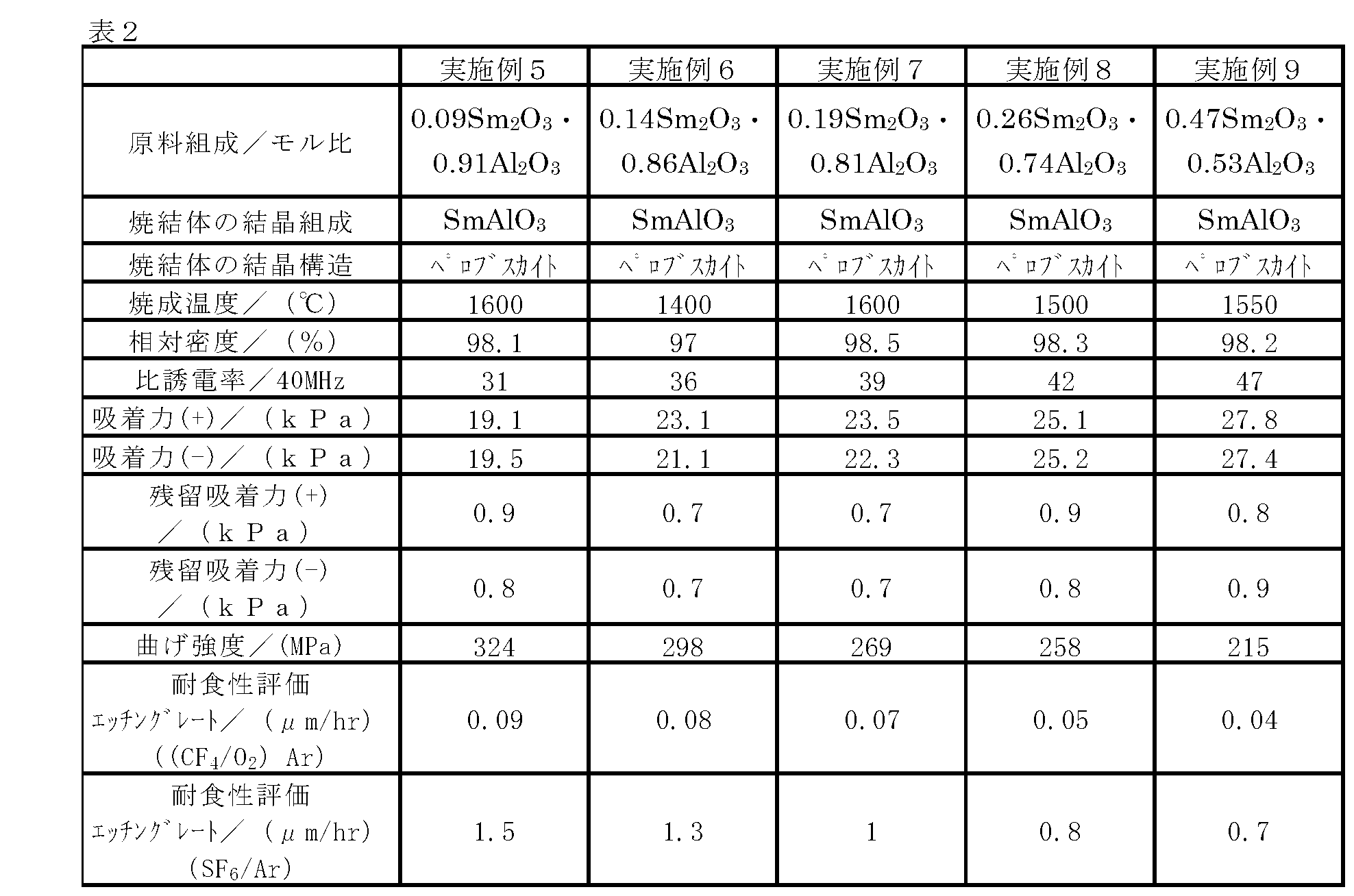
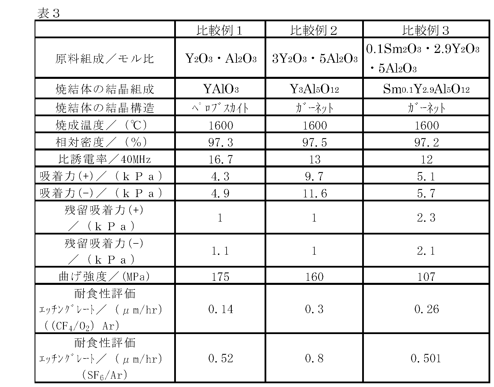
実施例1~9で得られた耐食性部材の比誘電率は比較例1~3で得られた耐食性部材の比誘電率に比べて高かった。これらの結果は、ペロブスカイト型構造はガーネット構造よりも分極が起こりやすいことと、サマリウムのイオン半径はイットリウムのイオン半径よりも大きいため分極が大きいこととによると予想される。
一方、実施例1~9で得られた耐食性部材の吸着力は比較例1~3で得られた耐食性部材の吸着力よりも大きかった。これより、実施例1~9で得られた耐食性部材を静電チャック用部材として使用することにより、シリコンウエハなどの基板を静電チャックにより確実に固定できることがわかった。
また、実施例1~9で得られた耐食性部材の残留吸着力は比較例1~3で得られた耐食性部材の残留吸着力よりも小さかった。これより、実施例1~9で得られた耐食性部材を静電チャック用部材として使用することにより、所定の処理が終わった後、シリコンウエハなどの基板を静電チャックからより容易に取り外せることがわかった。
実施例1~9で得られた耐食性部材の曲げ強度は比較例2および3で得られた耐食性部材の曲げ強度よりも強かった。これより、実施例1~9で得られた耐食性部材を静電チャック用部材として使用することにより、静電チャックの強度を高くすることができることがわかった。
Claims (7)
- サマリウムおよびアルミニウムを含み、ペロブスカイト型構造を有する酸化物を含む耐食性部材。
- 前記耐食性部材における前記酸化物の割合は80体積%以上である請求項1に記載の耐食性部材。
- 前記酸化物におけるサマリウム:アルミニウム(モル比)の範囲は、73:27~9:91である請求項1または2に記載の耐食性部材。
- 圧力が0.5Pa未満である雰囲気で、1mmの厚さを有する前記耐食性部材に2.0kVの電圧を60秒間印加して、1インチのシリコンウエハを前記耐食性部材に吸着させた後、電圧の印加を止めたときの残留吸着力が0.1~0.9kPaである請求項1~3のいずれか1項に記載の耐食性部材。
- 請求項1~4のいずれか1項に記載の耐食性部材を含む静電チャック用部材。
- 酸化アルミニウム粉末および酸化サマリウム粉末と溶媒とを混合して、前記酸化アルミニウム粉末および前記酸化サマリウム粉末を含むスラリーを作製する工程、
前記スラリーを乾燥して、前記アルミニウム粉末および前記酸化サマリウム粉末を含む混合粉末を作製し、該混合粉末を成形して成形体を作製する工程、および
前記成形体を焼成して焼結体を作製する工程を含む耐食性部材の製造方法。 - 前記焼結体をアニールする工程をさらに含む請求項6に記載の耐食性部材の製造方法。
Priority Applications (3)
| Application Number | Priority Date | Filing Date | Title |
|---|---|---|---|
| KR1020177003868A KR102246850B1 (ko) | 2014-09-29 | 2015-08-25 | 내식성 부재, 정전 척용 부재 및 내식성 부재의 제조 방법 |
| CN201580044157.7A CN106660884B (zh) | 2014-09-29 | 2015-08-25 | 耐蚀性部件、静电卡盘用部件及耐蚀性部件的制造方法 |
| US15/513,107 US10497599B2 (en) | 2014-09-29 | 2015-08-25 | Corrosion-resistant member, member for electrostatic chuck, and process for producing corrosion-resistant member |
Applications Claiming Priority (4)
| Application Number | Priority Date | Filing Date | Title |
|---|---|---|---|
| JP2014198317 | 2014-09-29 | ||
| JP2014-198317 | 2014-09-29 | ||
| JP2015131217A JP6156446B2 (ja) | 2014-09-29 | 2015-06-30 | 耐食性部材、静電チャック用部材および耐食性部材の製造方法 |
| JP2015-131217 | 2015-06-30 |
Publications (1)
| Publication Number | Publication Date |
|---|---|
| WO2016052010A1 true WO2016052010A1 (ja) | 2016-04-07 |
Family
ID=55630056
Family Applications (1)
| Application Number | Title | Priority Date | Filing Date |
|---|---|---|---|
| PCT/JP2015/073891 Ceased WO2016052010A1 (ja) | 2014-09-29 | 2015-08-25 | 耐食性部材、静電チャック用部材および耐食性部材の製造方法 |
Country Status (1)
| Country | Link |
|---|---|
| WO (1) | WO2016052010A1 (ja) |
Cited By (1)
| Publication number | Priority date | Publication date | Assignee | Title |
|---|---|---|---|---|
| JP2021097213A (ja) * | 2019-12-13 | 2021-06-24 | 株式会社デンソー | エレクトレット |
Citations (4)
| Publication number | Priority date | Publication date | Assignee | Title |
|---|---|---|---|---|
| JPS63236213A (ja) * | 1987-03-24 | 1988-10-03 | 住友金属鉱山株式会社 | 誘電体磁器 |
| JP2008297136A (ja) * | 2007-05-29 | 2008-12-11 | Taiheiyo Cement Corp | 半導体製造用セラミックス部品の製造方法及び装着方法 |
| JP2012094826A (ja) * | 2010-09-29 | 2012-05-17 | Sumitomo Osaka Cement Co Ltd | 静電チャック及びその製造方法 |
| WO2015056702A1 (ja) * | 2013-10-15 | 2015-04-23 | 住友大阪セメント株式会社 | 耐食性部材、静電チャック装置 |
-
2015
- 2015-08-25 WO PCT/JP2015/073891 patent/WO2016052010A1/ja not_active Ceased
Patent Citations (4)
| Publication number | Priority date | Publication date | Assignee | Title |
|---|---|---|---|---|
| JPS63236213A (ja) * | 1987-03-24 | 1988-10-03 | 住友金属鉱山株式会社 | 誘電体磁器 |
| JP2008297136A (ja) * | 2007-05-29 | 2008-12-11 | Taiheiyo Cement Corp | 半導体製造用セラミックス部品の製造方法及び装着方法 |
| JP2012094826A (ja) * | 2010-09-29 | 2012-05-17 | Sumitomo Osaka Cement Co Ltd | 静電チャック及びその製造方法 |
| WO2015056702A1 (ja) * | 2013-10-15 | 2015-04-23 | 住友大阪セメント株式会社 | 耐食性部材、静電チャック装置 |
Cited By (2)
| Publication number | Priority date | Publication date | Assignee | Title |
|---|---|---|---|---|
| JP2021097213A (ja) * | 2019-12-13 | 2021-06-24 | 株式会社デンソー | エレクトレット |
| JP7378087B2 (ja) | 2019-12-13 | 2023-11-13 | 株式会社デンソー | エレクトレット |
Similar Documents
| Publication | Publication Date | Title |
|---|---|---|
| JP7120398B2 (ja) | 溶射材料 | |
| JP5604888B2 (ja) | 静電チャックの製造方法 | |
| CN107098686B (zh) | 半导体制造装置用耐腐蚀性构件及其制法 | |
| JP6156446B2 (ja) | 耐食性部材、静電チャック用部材および耐食性部材の製造方法 | |
| KR20170141340A (ko) | 정전척용 세라믹 소결체 및 그 제조방법 | |
| JP5593694B2 (ja) | 耐食性部材及びその製造方法 | |
| JP5159625B2 (ja) | 窒化アルミニウム焼結体およびその製造方法 | |
| US8231964B2 (en) | Aluminum oxide sintered body, method for producing the same and member for semiconductor producing apparatus | |
| JP6015012B2 (ja) | 静電チャック部材 | |
| TW202229206A (zh) | 燒結體 | |
| JP5874248B2 (ja) | 静電チャック及びその製造方法 | |
| WO2016052010A1 (ja) | 耐食性部材、静電チャック用部材および耐食性部材の製造方法 | |
| JP2016155705A (ja) | 耐食性部材、その製造方法および静電チャック装置 | |
| JP2016160123A (ja) | 耐食性部材および静電チャック装置 | |
| JP2016155704A (ja) | 耐食性部材、その製造方法および静電チャック装置 | |
| JP2016188160A (ja) | 耐食性部材及び静電チャック用部材 | |
| JP2016154178A (ja) | 静電チャック用部材及びその製造方法 | |
| JP2009004752A (ja) | 静電チャック | |
| JP2023062501A (ja) | 焼結体及び半導体製造装置用部材 | |
| JP2009152570A (ja) | 静電チャック | |
| JP2009149496A (ja) | 導電性セラミック材料 | |
| JP2009149497A (ja) | 耐蝕性部材 |
Legal Events
| Date | Code | Title | Description |
|---|---|---|---|
| 121 | Ep: the epo has been informed by wipo that ep was designated in this application |
Ref document number: 15845837 Country of ref document: EP Kind code of ref document: A1 |
|
| ENP | Entry into the national phase |
Ref document number: 20177003868 Country of ref document: KR Kind code of ref document: A |
|
| WWE | Wipo information: entry into national phase |
Ref document number: 15513107 Country of ref document: US |
|
| NENP | Non-entry into the national phase |
Ref country code: DE |
|
| 122 | Ep: pct application non-entry in european phase |
Ref document number: 15845837 Country of ref document: EP Kind code of ref document: A1 |