WO2016047782A1 - 磁気センサ - Google Patents
磁気センサ Download PDFInfo
- Publication number
- WO2016047782A1 WO2016047782A1 PCT/JP2015/077192 JP2015077192W WO2016047782A1 WO 2016047782 A1 WO2016047782 A1 WO 2016047782A1 JP 2015077192 W JP2015077192 W JP 2015077192W WO 2016047782 A1 WO2016047782 A1 WO 2016047782A1
- Authority
- WO
- WIPO (PCT)
- Prior art keywords
- magnetic
- magnetic field
- magnetoresistive element
- free layer
- detection unit
- Prior art date
Links
Images


Classifications
-
- G—PHYSICS
- G01—MEASURING; TESTING
- G01R—MEASURING ELECTRIC VARIABLES; MEASURING MAGNETIC VARIABLES
- G01R33/00—Arrangements or instruments for measuring magnetic variables
- G01R33/02—Measuring direction or magnitude of magnetic fields or magnetic flux
- G01R33/06—Measuring direction or magnitude of magnetic fields or magnetic flux using galvano-magnetic devices
- G01R33/09—Magnetoresistive devices
- G01R33/098—Magnetoresistive devices comprising tunnel junctions, e.g. tunnel magnetoresistance sensors
-
- G—PHYSICS
- G01—MEASURING; TESTING
- G01R—MEASURING ELECTRIC VARIABLES; MEASURING MAGNETIC VARIABLES
- G01R33/00—Arrangements or instruments for measuring magnetic variables
- G01R33/0011—Arrangements or instruments for measuring magnetic variables comprising means, e.g. flux concentrators, flux guides, for guiding or concentrating the magnetic flux, e.g. to the magnetic sensor
-
- G—PHYSICS
- G01—MEASURING; TESTING
- G01R—MEASURING ELECTRIC VARIABLES; MEASURING MAGNETIC VARIABLES
- G01R33/00—Arrangements or instruments for measuring magnetic variables
- G01R33/02—Measuring direction or magnitude of magnetic fields or magnetic flux
- G01R33/038—Measuring direction or magnitude of magnetic fields or magnetic flux using permanent magnets, e.g. balances, torsion devices
-
- H—ELECTRICITY
- H10—SEMICONDUCTOR DEVICES; ELECTRIC SOLID-STATE DEVICES NOT OTHERWISE PROVIDED FOR
- H10N—ELECTRIC SOLID-STATE DEVICES NOT OTHERWISE PROVIDED FOR
- H10N50/00—Galvanomagnetic devices
- H10N50/10—Magnetoresistive devices
Definitions
- the present invention relates to a magnetic sensor.
- Patent Document 1 Japanese Patent Application Laid-Open No. 2006-3116 Patent Document 2 Japanese Patent Application Laid-Open No. 2006-10461 Patent Document 3 Japanese Patent Application Laid-Open No. Hei 7-169026 Patent Document 4 Japanese Patent Application Laid-Open No. 2002-71381 Patent Document 5 Japanese Patent Application Laid-Open No. 2004-6752 Patent Document 6 Japanese Patent Laid-Open No. 2003-282996 Patent Document 7 International Publication No. 2011/068146 Pamphlet
- the TMR element has a linear region that generates a resistance value substantially proportional to the external magnetic field and a saturation region that generates a predetermined resistance value regardless of the external magnetic field.
- a magnetic sensor using a TMR element cannot accurately detect an external magnetic field unless it is in a linear region. Therefore, the detection range of the external magnetic field is limited to the magnitude of the saturation magnetic field of the TMR element.
- one TMR element has a direction different from the magnetic sensitive axis direction and the magnetic sensitive axis direction. Therefore, there is a problem that magnetic field saturation is likely to occur.
- the substrate, the magnetic converging portion disposed on or in the substrate and having one or more magnetic converging members, disposed in the vicinity of the magnetic converging member, and the plane of the substrate
- a plurality of magnetic detectors having a magnetosensitive axis in a direction parallel to the first and second outputs, and an external magnetic field in the direction of the first axis parallel to the plane of the substrate, parallel to the plane of the substrate and
- the magnetic converging unit converts each external magnetic field in a direction different from the direction of the magnetic sensitive axis into a magnetic field in the direction of the magnetic sensitive axis at each magnetic detection unit of the plurality of magnetic detection units, and each magnetic detection unit is parallel to the plane of the substrate.
- a plurality of magnetoresistive elements arranged, and each magnetoresistive element of the plurality of magnetoresistive elements is Includes a laminated structure of a free layer whose magnetization direction changes due to an external magnetic field, a pinned layer whose magnetization is fixed, and a spacer layer provided between the free layer and the pinned layer, and is included in multiple magnetoresistive elements
- the longitudinal direction of the free layer of the one magnetoresistive element and the longitudinal direction of the free layer of at least one magnetoresistive element adjacent to the one magnetoresistive element are the same direction, and at least adjacent to the one magnetoresistive element
- One magnetoresistive element provides a magnetic sensor arranged in the longitudinal direction of the free layer of one magnetoresistive element.
- FIG. 1 shows an exemplary configuration of a magnetic sensor 100.
- FIG. 5 is a diagram for explaining the operation of the magnetic sensor 100. 1 shows an exemplary configuration of a magnetic sensor 100.
- FIG. 1 shows an example of a plan view of the magnetic detection unit 110.
- the plan view refers to a view seen from the positive side in the Z-axis direction.
- 2 to 4 show examples of cross-sectional views taken along line AA ′ of the magnetic detection unit 110 in FIG.
- the magnetic detection unit 110 includes a substrate 10, a magnetoresistive element 20, a lower electrode 30, an upper electrode 40, and an element isolation insulating film 50. In FIG. 1, the substrate 10 and the element isolation insulating film 50 are omitted.
- the magnetic detection unit 110 detects an external magnetic field.
- the substrate 10 may be any of a silicon substrate, a compound semiconductor substrate, and a ceramic substrate.
- the substrate 10 may be a silicon substrate on which an IC is mounted.
- the magnetoresistive element 20 is formed above the substrate 10.
- the magnetic detection unit 110 of this example has a plurality of magnetoresistive elements 20 a to 20 d and is arranged in a direction parallel to the plane of the substrate 10.
- Each magnetoresistive element 20 includes a pinned layer 21, a spacer layer 22, and a free layer 23.
- the magnetoresistive element 20 is a TMR element.
- a TMR element refers to an element in which an extremely thin insulating film is sandwiched between magnetic thin films. The resistance of the TMR element varies depending on the magnetization direction of the magnetic thin film sandwiching the insulating film.
- the free layer of the magnetoresistive element 20 of this example has a rectangular cross section having a length L and a width W in plan view.
- Plan view refers to the case when viewed from the positive side of the Z-axis.
- the plurality of magnetoresistive elements 20 are arranged in the longitudinal direction (Y-axis direction) of the magnetoresistive elements 20.
- the magnetoresistive elements 20 may be electrically connected to each other.
- the magnetoresistive element 20 only needs to have a rectangular cross section of at least the free layer 23 in plan view.
- the longitudinal direction of the magnetoresistive element 20 is the same as the longitudinal direction of the free layer 23.
- the pinned layer 21 is made of a magnetic material whose magnetization is fixed in a predetermined direction.
- the pinned layer 21 is formed by a combination of materials such as Co, Fe, and Ni.
- the axis in the direction in which the magnetization of the pinned layer 21 is fixed is referred to as a magnetosensitive axis.
- the spacer layer 22 is a thin film insulator formed on the pinned layer 21.
- the spacer layer 22 is formed of an insulating material such as Al 2 O 3 or MgO.
- the free layer 23 is a magnetic material whose magnetization direction changes according to an external magnetic field.
- the free layer 23 is a soft magnetic material formed by a combination of materials such as Co, Fe, and Ni.
- the free layer 23 is formed on the spacer layer 22.
- the magnetization direction of the free layer 23 is caused by the shape anisotropy of the free layer 23 and is the longitudinal direction (Y-axis direction) of the magnetoresistive element 20.
- the magnetization direction of the free layer 23 in this example is the same as the arrangement direction of the free layers 23.
- the lower electrode 30 is provided between the substrate 10 and the magnetoresistive element 20.
- the lower electrode 30 connects the pinned layers 21 of two adjacent magnetoresistive elements 20 to each other.
- the lower electrode 30 of this example connects the magnetoresistive element 20a and the magnetoresistive element 20b, and the magnetoresistive element 20c and the magnetoresistive element 20d, respectively.
- the lower electrode 30 is made of, for example, a nonmagnetic material.
- the upper electrode 40 is provided on the magnetoresistive element 20.
- the upper electrode 40 connects the free layers 23 of the two adjacent magnetoresistive elements 20 to each other.
- the upper electrode 40 of this example connects the magnetoresistive element 20b and the magnetoresistive element 20c. That is, the adjacent magnetoresistive elements 20 are electrically connected by either the lower electrode 30 or the upper electrode 40.
- the lower electrode 30 and the upper electrode 40 of this example have a rectangular cross section in plan view, but are not limited thereto. The widths of the lower electrode 30 and the upper electrode 40 may be the same.
- the element isolation insulating film 50 electrically isolates the free layers of the adjacent magnetoresistive elements 20 from each other.
- the element isolation insulating film 50 is formed of an insulating material used in a general semiconductor manufacturing process.
- the element isolation insulating film 50 is formed by silicon dioxide SiO 2.
- the magnetic detection unit 110 has the free layer 23 that is magnetized in the direction orthogonal to the magnetosensitive axis and arranged. Thereby, the magnetic detection unit 110 can accurately detect a magnetic field in the same direction as the magnetosensitive axis.
- the side surfaces of the two magnetoresistive elements 20 connected by the lower electrode 30 are completely separated by the element isolation insulating film 50.
- To completely separate refers to physically separating adjacent magnetoresistive elements 20 so as not to contact each other.
- the pinned layer 21, the spacer layer 22, and the free layer 23 are completely etched between the magnetoresistive element 20a and the magnetoresistive element 20b.
- the two magnetoresistive elements 20 connected by the lower electrode 30 are connected to each other on the side surface of the pinned layer 21.
- the spacer layer 22 and the free layer 23 are completely etched between the magnetoresistive element 20a and the magnetoresistive element 20b.
- the pinned layer 21 may not be completely etched between the magnetoresistive element 20a and the magnetoresistive element 20b, and a part thereof may remain. Further, the pinned layer 21 may be used as the pinned layer / lower electrode without providing the lower electrode 30.
- the two magnetoresistive elements 20 connected by the lower electrode 30 are connected to each other at the side surfaces of the pinned layer 21 and the spacer layer 22.
- the spacer layer 22 is not completely etched and a part is left.
- the pinned layer 21 may be used as the pinned layer / lower electrode without providing the lower electrode 30.
- the pinned layer 21 or the spacer layer 22 may be in contact with each other as long as at least the free layer 23 is completely separated by the element isolation insulating film 50.
- the pinned layer 21 and the spacer layer 22 may have any shape of a quadrangle, a square, a parallelogram, a trapezoid, a triangle, a polygon, a circle, and an ellipse in plan view.
- FIG. 5 shows an example of the magnetic detection unit 110.
- FIG. 6 shows an example of the magnetic detection unit 115.
- the magnetic detection unit 110 of this example has basically the same structure as the magnetic detection unit 110 shown in FIG.
- Both the pinned layer 21 of the magnetic detection unit 110 and the magnetic detection unit 115 have a magnetosensitive axis in the X-axis direction.
- the free layers 23 of the magnetic detection unit 110 and the magnetic detection unit 115 both have a longitudinal direction in the Y-axis direction and a magnetization direction in the Y-axis direction. Therefore, in both cases of the magnetic detection unit 110 and the magnetic detection unit 115, the magnetization direction of the pinned layer 21 and the magnetization direction of the free layer 23 are orthogonal to each other.
- Adjacent magnetoresistive elements 20 are electrically connected by either the lower electrode 30 or the upper electrode 40.
- the width of the upper electrode 40 in this example is larger than the width of the lower electrode 30.
- the width of the upper electrode 40 may be the same as the width of the lower electrode 30 or may be smaller than the width of the lower electrode 30.
- the arrangement direction of the magnetoresistive elements 20 is different between the magnetic detection unit 110 and the magnetic detection unit 115.
- the free layers 23 are arranged in the Y-axis direction. That is, the longitudinal direction (Y axis) of the free layer 23 of one magnetoresistive element 20 included in the plurality of magnetoresistive elements 20 and the free layer 23 of at least one magnetoresistive element 20 adjacent to the one magnetoresistive element 20.
- the at least one magnetoresistive element 20 adjacent to one magnetoresistive element 20 is the same as the longitudinal direction (Y axis) of the free layer 23 of one magnetoresistive element 20. ).
- the free layer 23 is arranged in the longitudinal direction (Y axis) of the free layer 23, which is a direction orthogonal to the magnetosensitive axis (X axis) of the pinned layer 21.
- the arrangement method of the free layers 23 in this example is referred to as longitudinal series.
- the free layers 23 are arranged in the X-axis direction. That is, the magnetoresistive elements 20 adjacent to one magnetoresistive element 20 are arranged in the short direction (X axis) of the free layer 23 of the one magnetoresistive element 20.
- the free layer 23 is arranged in the short direction (X axis) of the free layer 23, which is a direction parallel to the magnetosensitive axis (X axis) of the pinned layer 21.
- the arrangement method of the free layers 23 in this example is referred to as horizontal series.
- FIG. 7 shows the rate of resistance change when an external magnetic field is applied to the magnetic detection unit 110 and the magnetic detection unit 115.
- the horizontal axis represents the external magnetic field ( ⁇ T) applied to the magnetic detection unit
- the vertical axis represents the resistance change rate (%).
- Thick lines indicate longitudinal series resistance to ascending field resistance and descending field.
- the ascending magnetic field resistance change rate refers to the resistance change rate when the strength of the external magnetic field applied to the magnetic detection unit is gradually increased from a small value to a large value.
- the falling magnetic field resistance change rate refers to the resistance change rate when the strength of the external magnetic field applied to the magnetic detection unit is gradually lowered from a large value to a small value.
- the alternate long and short dash line indicates the rate of change in resistance of the rising magnetic field in the horizontal series
- the dotted line indicates the rate of change in resistance of the magnetic field drop in the horizontal series.
- the curve showing the resistance change rate in the vertical series has a smaller slope than the curve showing the resistance change rate in the horizontal series. That is, in the vertical series, the change amount of the resistance change rate with respect to the change of the applied magnetic field is smaller than that in the horizontal series.
- the resistance change rates of the magnetic detection unit 110 and the magnetic detection unit 115 are saturated when they exceed a certain magnitude. For this reason, when the absolute value of the applied magnetic field exceeds a certain value, it becomes impossible to detect a change in the resistance change rate.
- the slope of the resistance change rate is smaller than that in the case of the lateral series, the maximum value of the applied magnetic field that can be detected becomes larger than in the case of the lateral series. Therefore, in the case of vertical series, magnetic field saturation is less likely to occur than in the case of horizontal series, and the range of the detected magnetic field is wide.
- the longitudinal series a curve indicating the rate of change in the rising magnetic field resistance and a curve indicating the rate of change in the descending magnetic field resistance overlap.
- the longitudinal series has a smaller difference between the rate of change in the ascending magnetic field resistance and the rate of change in the descending magnetic field resistance, that is, the hysteresis, compared to the horizontal series.
- the hysteresis since the hysteresis is small, the error between the case where the applied magnetic field is an ascending magnetic field and the case where it is a descending magnetic field is small, and the detection accuracy is high.
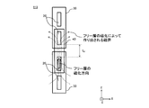
- FIG. 8 is a diagram for explaining the reason why the range of the detected magnetic field becomes wider compared to the vertical series in the horizontal series.
- the magnetic field generated by the free layers 23 of the magnetoresistive elements 20 is the magnetization direction of the free layers 23 of the adjacent magnetoresistive elements 20 ( A magnetic field along the Y axis direction is created.
- the interval L f indicates the interval between the free layers 23.
- Distance L f is the materials used, may be set to any size.
- the interval L f may be 15 ⁇ m or less, and may be 5 ⁇ m or 10 ⁇ m.
- the distance L f may be any 0 ⁇ m greater than.
- FIG. 9 is a diagram for explaining a bias magnetic field applied to the free layer 23.
- the free layer 23 of each magnetoresistive element 20 functions as a bias magnet for the adjacent free layer 23. That is, a bias magnet composed of an N pole and an S pole arranged in the Y-axis direction is formed at both ends of each free layer 23 in a pseudo manner.
- FIG. 10 shows an example of the magnetic sensor 100.
- the magnetic sensor 100 includes a magnetic converging unit 65, magnetic detection units 70a to 70c, and metal wirings 80a to 80c.
- the magnetic detection unit 70 of this example has the same TMR element as the magnetic detection unit 110 arranged in series.
- the magnetic detection unit 70 only needs to have at least one magnetic detection unit 110 arranged in series in the vertical direction, and it is not necessary that all the magnetic detection units 110 are arranged in series in the vertical direction.
- the magnetic sensor 100 detects the input external magnetic field.
- the external magnetic field can be considered as being divided into external magnetic fields B X , B Y , and B Z that are uniform in the X-axis, Y-axis, and Z-axis directions.
- the magnetic convergence unit 65 converges the input external magnetic field to the magnetic detection unit 70.
- the magnetic flux concentrator 65 is disposed on or in the substrate 10.
- the magnetic focusing unit 65 has one or a plurality of magnetic focusing members 60.
- the magnetic converging unit 65 of this example includes magnetic converging members 60a to 60f.
- the magnetic flux concentrator members 60a to 60f are formed on the magnetic detectors 70a to 70c and the metal wirings 80a to 80d.
- the magnetic flux concentrator members 60a to 60f are cuboids having a thickness in the Z-axis direction and a longitudinal direction in the Y-axis direction.
- the corners of the magnetic flux concentrator member 60 in this example are right angles, but at least one of the four corners may be rounded or chamfered.
- the shape of the magnetic flux concentrator members 60a to 60f may be any shape of a quadrangle, a square, a parallelogram, a trapezoid, a triangle, a polygon, a circle, and an ellipse in plan view.
- the magnetic flux concentrator members 60a to 60f may be formed of a soft magnetic material such as NiFe, NiFeB, NiFeCo, CoFe.
- the magnetic flux concentrator members 60a to 60f are arranged side by side in the X-axis direction.
- the magnetic flux concentrator members 60a, 60c, and 60e in this example are arranged so as to be shifted to the positive side in the Y-axis direction with respect to the magnetic flux convergent members 60b, 60d, and 60f.
- the magnetic flux concentrator members 60a to 60f are substantially parallel to the substrate 10 and substantially parallel to each other.
- the magnetic detection unit 70 is disposed in the vicinity of the magnetic converging member 60 and has a magnetic sensitive axis in a direction parallel to the plane of the substrate 10.
- the magnetic detection unit 70 includes the pinned layer 21 that is magnetized in the + X-axis direction.
- the magnetic detectors 70a to 70c in this example are arranged corresponding to the positive side of the X axis of each of the magnetic flux concentrator members 60b, 60d, and 60f.
- the magnetic detection unit 70 of this example is a rectangle having a longitudinal direction in the Y-axis direction in plan view.
- the magnetic detection unit 70 may have any shape of a square, a square, a parallelogram, a trapezoid, a triangle, a polygon, a circle, and an ellipse in plan view.
- the metal wiring 80 connects the magnetic detection units 70 to each other.
- the current i flows through the metal wirings 80a to 80d, the current i flows through the magnetic detection units 70a to 70c, respectively.
- the resistance values of the magnetic detectors 70a to 70c changed by the external magnetic field can be detected by the current i flowing through the magnetic detectors 70a to 70c.
- the magnetic detection unit 70 responds to a magnetic field applied in the direction of the magnetosensitive axis. Therefore, the magnetic detection unit 70 detects the magnetic field applied in the X-axis direction when the direction of the magnetosensitive axis is the X-axis direction, but is insensitive to the magnetic fields applied in the Y-axis direction and the Z-axis direction. .
- the magnetic resistance RTMR of the magnetic detection unit 70 is expressed as follows.
- R TMR R 0 + ⁇ R X
- R 0 indicates the resistance value of the magnetic detection unit 70 that does not depend on the external magnetic field.
- ⁇ R X indicates a resistance change amount of the magnetic detection unit 70 according to the magnitude of the external magnetic field B X.
- External magnetic field B X may be converged by the magnetic flux concentrator member 60b, it traverses toward the magnetic detecting portion 70a on the positive side of the X-axis direction. Similarly, the external magnetic field B X crosses the magnetic detection unit 70b, a 70c. That is, the external magnetic field B X is detected by the magnetic detection unit 70a ⁇ 70c. When a current i through the metal wires 80a ⁇ 80d, can detect an external magnetic field B X by the magnetic detector 70a ⁇ 70c has detected.
- the magnetic path of the external magnetic field BY is indicated by three magnetic focusing members 60c, 60d and 60e and a magnetic detection unit 70b.
- the external magnetic field BY When the external magnetic field BY is input to the magnetic focusing member 60d protruding in the ⁇ Y-axis direction, the external magnetic field BY branches and flows into each of the magnetic focusing members 60c and 60e.
- the external magnetic field BY flows on the negative side in the X-axis direction.
- the external magnetic field BY flows on the positive side in the X-axis direction.
- the external magnetic field BY is converted in the X-axis direction and crosses the magnetic detection unit 70b.
- the external magnetic field BY input to the magnetic focusing members 60b and 60f is converted in the X-axis direction and crosses the magnetic detection units 70a and 70c.
- the external magnetic field BY is detected by the magnetic detectors 70a to 70c.
- the current i is supplied through the metal wirings 80a to 80d, the external magnetic field BY detected by the magnetic detection units 70a to 70c can be detected.
- the magnetic path of the external magnetic field B Z indicated by the magnetic flux concentrator member 60b and the magnetic detector 70a.
- the magnetic detector 70 is formed on the negative side of the Z axis with respect to the magnetic flux concentrator member 60, the external magnetic field B Z traverses toward the magnetic detection unit 70a to the negative side of the X-axis direction, the magnetic flux concentrator A magnetic path converged on the member 60b is formed. That is, the external magnetic field BZ is converted in the X-axis direction and crosses the magnetic detection unit 70a. Similarly, the external magnetic field B Z which is input to the magnetic flux concentrator member 60d and 60f is converted into X-axis direction, crossing the magnetic detection unit 70b, a 70c. Thus, the external magnetic field B Z is detected by the magnetic detector 70a ⁇ 70c. When the electric current i through the metal wires 80a ⁇ 80d, can detect an external magnetic field B Z which magnetic detection unit 70a ⁇ 70c has detected.
- the magnetic sensor 100 can detect the magnetic field in the triaxial direction by converting the direction of the external magnetic field into the direction of the magnetosensitive axis by the magnetic converging members 60a to 60f.
- Reluctance R TMR of the magnetic detector 70a ⁇ 70c of the present embodiment is expressed as follows.
- R TMR R 0 + ⁇ R X + ⁇ R Y ⁇ R Z
- ⁇ R Y is a resistance change amount according to the magnitude of the external magnetic field BY
- ⁇ R Z is a resistance change amount according to the magnitude of the external magnetic field B Z.
- FIG. 11 shows an example of the configuration of the magnetic sensor 100.
- 11A is a plan view of the magnetic sensor 100
- FIG. 11B is a cross-sectional view taken along the line AA of FIG. 11A.
- the magnetic sensor 100 of this example includes magnetic converging members 60a to 60c and magnetic detection units 70a to 70e having a magnetosensitive axis in the X-axis direction.
- the magnetic sensor 100 detects three orthogonal magnetic signals.
- the magnetic detectors 70a to 70e of this example have the same structure.
- the magnetic flux concentrator members 60a to 60c are arranged in parallel with each other in the X-axis direction.
- the magnetic convergence member 60a and the magnetic convergence member 60c are provided with the magnetic convergence member 60b interposed therebetween. Further, the magnetic flux concentrator member 60a and the magnetic flux convergent member 60c are arranged so as to be shifted to the positive side in the Y-axis direction with respect to the magnetic flux convergent member 60b. More specifically, a plane (XZ plane) orthogonal to the Y-axis direction including one end point 161 does not intersect the magnetic focusing member 60a and the magnetic focusing member 60c, and at the same time in the Y-axis direction including the other end point 162.
- An orthogonal plane (XZ plane) is arranged so as to intersect with the magnetic flux concentrator member 60a and the magnetic flux convergent member 60c.
- XZ plane an orthogonal plane
- the end point 161 and the end point 162 indicate a positive end point and a negative end point in the Y-axis direction of the magnetic flux concentrator member 60 b overlapping the first virtual plane 61.
- the first virtual plane 61 is an arbitrary virtual plane substantially parallel to the substrate plane 11.
- the first virtual plane 61 of this example corresponds to the negative bottom surface in the Z-axis direction of the magnetic flux concentrator members 60a to 60c.
- the bottom surfaces on the negative side in the Z-axis direction of the magnetic flux concentrator members 60a to 60c may be different planes from the first virtual plane 61, respectively.
- the shape of the magnetic flux concentrator member 60 that overlaps the first virtual plane 61 is not limited to a rectangle, and may be any of a quadrilateral having a longitudinal direction in a direction substantially parallel to the Y-axis direction, a parallelogram, and a trapezoid.
- the thicknesses of the magnetic flux concentrator members 60a to 60c in the Z-axis direction may be the same or different.
- the first inter-edge distance Lab is a distance in which the magnetic converging member 60a and the magnetic converging member 60b overlapping the first virtual plane 61 are the shortest along the X-axis direction in the first range R1.
- the second inter-edge distance Lbc is the distance in which the magnetic converging member 60b and the third magnetic converging member 60c overlapping the first virtual plane 61 are the shortest along the X-axis direction in the second range R2.
- the first range R1 means that the plane perpendicular to the Y-axis direction between the magnetic flux concentrator member 60a and the magnetic flux concentrator member 60b intersects both the magnetic flux concentrator member 60a and the magnetic flux concentrator member 60b. This is a range along the Y-axis direction.
- the second range R2 is that the plane perpendicular to the Y-axis direction between the magnetic flux concentrator member 60c and the magnetic flux concentrator member 60b intersects both the magnetic flux concentrator member 60c and the magnetic flux convergent member 60b. It is a range along the Y-axis direction.
- the first edge distance Lab in this example is substantially equal to the second edge distance Lbc.
- the first inter-edge distance Lab and the second inter-edge distance Lbc may be in a range of 0.7 to 1.3 times one of the distances. If it is this range, the magnetic sensor 100 can suppress the dispersion
- the magnetic detection units 70a and 70b are disposed between the magnetic converging member 60a and the magnetic converging member 60b in plan view. As long as at least one part of the magnetic detection units 70a and 70b is arranged in the first range R1, all of them may be arranged in the first range R1.
- the magnetism detection units 70d and 70e are arranged between the magnetic flux concentrator member 60b and the magnetic flux convergent member 60c in plan view. Further, at least one part of the magnetic detection units 70d and 70e may be arranged in the second range R2, and all of them may be arranged in the second range R2.
- the magnetic detection unit 70c is arranged so as to be insensitive to the magnetic field in the triaxial direction when covered with the magnetic converging member 60b in plan view.
- the magnetic detection part 70c may be arrange
- the length (width) in the X-axis direction of the magnetic flux concentrator member 60b may be in a range that covers the entire magnetic detection unit 70c and that provides a sufficient magnetic shielding effect for the magnetic detection unit 70c.
- the width of the magnetic flux concentrator member 60b is preferably 1.5 times or more, more preferably 3 times or more the width of the magnetic detector 70c.
- the magnetic detection unit 70a is disposed between the magnetic converging member 60a and the magnetic converging member 60b, and is disposed so as to be close to the magnetic converging member 60a. Moreover, the magnetic detection part 70b is arrange
- the second virtual plane 71 Is disposed so as to be closer to the magnetic converging member 60a than the virtual midline VM.
- the magnetic detection unit 70a has a distance M11 of a side where the shape of the magnetic flux concentrator member 60a that overlaps the first virtual plane 61 and the shape of the magnetic detection unit 70a that overlaps the second virtual plane 71 are closest to each other.
- the magnetic converging member 60b that overlaps the first virtual plane 61 and the magnetic detection unit 70a that overlaps the second virtual plane 71 are arranged so that the shape is shorter than the distance M12 between the sides closest to each other.
- the magnetic detection unit 70b is arranged such that the shape of the magnetic detection unit 70b that overlaps the second virtual plane 71 is closer to the magnetic convergence member 60b than the virtual midline VM.
- the second virtual plane 71 is an arbitrary virtual plane substantially parallel to the substrate plane 11.
- the second virtual plane 71 corresponds to the bottom surface on the negative side of the magnetic detection units 70a to 70e in the Z-axis direction.
- the magnetic detection units 70a to 70e are arranged so that the bottom surfaces thereof are in contact with the second virtual plane 71, but a part of each is arranged so as to intersect the second virtual plane 71. Also good. Further, the thicknesses of the magnetic detectors 70a to 70e in the Z-axis direction may be the same or different.
- the first to fourth intermediate line distances L1 to L4 the first and second virtual middle lines VM1 and VM2, and the first to fourth virtual lines I1 to I1 I4 is used.
- the first virtual midline VM1 is a line that is in the middle of the sides where the magnetic converging member 60a and the magnetic converging member 60b that overlap the first virtual plane 61 are closest to each other.
- the first midline distance L1 is a line connecting the first virtual midline VM1 and the midpoint of the two end sides perpendicular to the X-axis direction of the magnetic detection unit 70a overlapping the second virtual plane 71.
- the second interline distance L2 is an intermediate point between two edges perpendicular to the first virtual middle line VM1 and the second magnetoresistive element 70b overlapping the second virtual plane 71 in the X-axis direction. This is the distance from the line connecting the points.
- the second virtual midline VM2 is a line that is the middle of the sides where the magnetic converging member 60b and the magnetic converging member 60c that overlap the first virtual plane 61 are closest to each other.
- the third midline distance L3 is a line connecting the second virtual midline VM2 and the midpoint of the two end sides perpendicular to the X-axis direction of the magnetic detection unit 70d that overlaps the second virtual plane 71.
- the fourth interline distance L4 is defined as an intermediate point between the second virtual midline VM2 and the two end sides perpendicular to the X-axis direction of the magnetic detection unit 70e overlapping the second virtual plane 71. It is the distance from the connecting line.
- first virtual line I1 is a straight line parallel to the X-axis direction including the midpoint between the end points in the Y-axis direction of the magnetic detection unit 70a within the first range R1.
- the second virtual line I2 is a straight line parallel to the X-axis direction including the midpoint between the end points in the Y-axis direction of the second magnetoresistive element 70b within the first range R1.
- the third imaginary line I3 is a straight line parallel to the X-axis direction including the midpoint between the end points in the Y-axis direction of the magnetic detection unit 70d within the second range R2.
- fourth imaginary line I4 is a straight line parallel to the X-axis direction including the midpoint between the end points in the Y-axis direction of the magnetic detection unit 70e within the second range R2.
- the first midline distance L1 is the intersection of the first imaginary line I1 and the first imaginary center line VM1 and the midpoint of the two end points of the magnetic detection unit 70a that intersects the first imaginary line I1. It is the length of the connecting line segment.
- the second interline distance L2 is the intersection of the second imaginary line I2 and the first imaginary center line VM1 and the two end points of the second magnetoresistive element 70b intersecting the second imaginary line I2. This is the length of the line segment connecting with the midpoint.
- the third midline distance L3 is the midpoint between the intersection of the third virtual line I3 and the second virtual midline VM2 and the two end points of the magnetic detection unit 70c intersecting the third virtual line I3. It is the length of the line segment connecting with.
- the fourth interline distance L4 is an intersection of the fourth imaginary line I4 and the second imaginary center line VM2, and a midpoint between the two end points of the magnetic detection unit 70d that intersects the fourth imaginary line I4. , Is the length of the line segment.
- the magnetic detectors 70a, 70b, 70d and 70e and the magnetic flux concentrator members 60a to 60c include a first interline distance L1, a second interline distance L2, and a third interline distance L3.
- the fourth center line distance L4 is substantially equal.
- the first to fourth midline distances L1 to L4 may be in a range of 0.7 to 1.3 times the distance of any one. In this range, the magnetic sensor 100 can suppress variations in sensitivity with respect to the external magnetic field in the triaxial direction.
- FIG. 12 is a diagram for explaining the operation of the magnetic sensor 100.
- An arrow indicates a magnetic path in which an external magnetic field travels.
- External magnetic field B X may be converged to the magnetic flux concentrator member 60a, across the magnetic detection unit 70a and the magnetoresistive element 70b to the positive side of the X-axis direction, as is converged to the magnetic flux concentrator member 60b, the magnetic detection unit 70d and the magnetic
- the detector 70e is crossed to the positive side in the X-axis direction and converged on the magnetic convergence member 60c. At this time, magnetic detectors 70a, 70b, 70d and 70e detects the external magnetic field B X.
- the external magnetic field BY passes through the magnetic converging member 60b protruding to the negative side of the Y axis and branches to the magnetic converging members 60a and 60c.
- the magnetoresistive elements 70b and 70a are crossed to the negative side in the X-axis direction.
- the magnetoresistive elements 70d and 70e are crossed to the positive side in the X-axis direction.
- the magnetic detectors 70a, 70b, 70d, and 70d detect the magnetic field in the X-axis direction whose direction is changed in proportion to the magnitude of the external magnetic field BY .
- the magnetic detector 70a In the external magnetic field BZ , the magnetic detector 70a is crossed toward the negative side of the X axis, the magnetic path converged on the magnetic converging member 60a and the magnetoresistive element 70b are crossed on the positive side of the X axis direction, and the magnetic converging member A magnetic path converged to 60b is formed. Also, the external magnetic field B Z, across the magnetic detection unit 70d on the negative side of the X-axis direction, a magnetic path is converged to the magnetic flux concentrator member 60b, across the magnetic detection portion 70e on the positive side of the X-axis direction, the magnetic flux concentrator A magnetic path converged on the member 60c is formed. At this time, the magnetic detectors 70a, 70b, 70d, and 70e detect the magnetic field in the X-axis direction whose direction is changed in proportion to the magnitude of the magnetic field input from the Z-axis direction.
- FIG. 13 shows an example of the configuration of the magnetic sensor 100.
- the magnetic sensor 100 of this example includes output terminals A to E and S and a calculation unit 90.
- the output terminal S is a terminal in which one terminal of the magnetic detection units 70a to 70e is electrically coupled to one point. By coupling the terminals to one point, the number of output terminals can be reduced.
- Output terminals A to E are output terminals to which the other terminals of the magnetic detectors 70a to 70e are connected.
- R A R 0 + ⁇ R X ⁇ R Y ⁇ R Z (Equation 1)
- R B R 0 + ⁇ R X ⁇ R Y + ⁇ R Z (Expression 2)
- R C R 0 + ⁇ R X + ⁇ R Y ⁇ R Z (Equation 3)
- R D R 0 + ⁇ R X + ⁇ R Y + ⁇ R Z (Expression 4)
- R E R 0 (Expression 5)
- Each of the magnetic resistances of the formulas (1) to (4) includes resistance change amounts ⁇ R X , ⁇ R Y , and ⁇ R Z corresponding to the magnitude of the external magnetic field in the three-axis directions.
- the signs of ⁇ R X , ⁇ R Y , and ⁇ R Z correspond to the direction of the magnetic field in the X-axis direction across the magnetic detectors 70a, 70b, 70d, and 70e. Since the magnetoresistance of equation (5) is insensitive to the external magnetic field in the triaxial direction, it does not include any resistance change amount of the triaxial component.
- the arithmetic unit 90 is connected to each of the terminals A, B, and C.
- the calculation unit 90 calculates based on the outputs of the magnetic detection units 70a to 70e. For example, when the output signal S corresponding to the resistance change amount corresponding to the magnitude of the magnetic field of each axis is extracted from the magnetic resistances of the equations (1) to (5), (Equation 1)-(Equation 5)
- the calculation unit 90 of this example calculates the resistance change amounts ⁇ R X , ⁇ R Y , and ⁇ R Z according to the magnitudes of the external magnetic fields in the three-axis directions based on the outputs of the magnetic detection units 70a to 70e. I can take it out. That is, an external magnetic field in the three-axis direction can be obtained by solving a series of cubic equations related to the resistance values of the magnetic detectors 70a to 70e. As described above, the magnetic sensor 100 according to the present embodiment can detect the external magnetic field in the three-axis directions with a simple configuration, and thus can further reduce the size and space of the device.
- the TMR element having the insulating spacer layer 22 is used as the magnetic detection unit 70, but a giant magnetoresistive (GMR) element in which the spacer layer 22 is formed of a conductive layer is used. It may be used.
- the method of detecting an external magnetic field when a GMR element is used as the magnetic detection unit 70 is the same as when a TMR element is used as the magnetic detection unit 70. Even when a GMR element is used as the magnetic detection unit 70, the magnetic sensor 100 can achieve a large magnetic field range and a small hysteresis. Further, the magnetic sensor 100 can detect an external magnetic field in the triaxial direction with a simple configuration.
Abstract
磁場レンジが広い磁気センサを提供する。基板と、基板上又は基板内に配置され、磁気収束部と、複数の磁気検出部と、演算部とを備え、磁気収束部は、複数の磁気検出部の各磁気検出部で、感磁軸方向と異なる方向の外部磁場を感磁軸方向の磁場に変換し、各磁気検出部は、基板の平面に平行に配列された複数の磁気抵抗素子を含み、複数の磁気抵抗素子の各磁気抵抗素子は、外部磁場により磁化の方向が変化するフリー層と、磁化が固定されたピンド層と、フリー層とピンド層との間に設けられたスペーサ層との積層構造を含み、複数の磁気抵抗素子に含まれる一の磁気抵抗素子のフリー層の長手方向と、一の磁気抵抗素子に隣り合う少なくとも1つの磁気抵抗素子のフリー層の長手方向とが同じ方向であり、一の磁気抵抗素子に隣り合う少なくとも1つの磁気抵抗素子は、一の磁気抵抗素子のフリー層の長手方向に配列される磁気センサを提供する。
Description
本発明は、磁気センサに関する。
従来、予め定められた一方向の磁気の有無を検出するトンネル磁気抵抗(TMR:Tunnel Magneto-Resistance)素子が知られていた。また、磁気抵抗素子と、磁気収束部とを組み合わせた磁気センサが知られていた(例えば、特許文献1~7参照)。
特許文献1 特開2006-3116号公報
特許文献2 特開2006-10461号公報
特許文献3 特開平7-169026号公報
特許文献4 特開2002-71381号公報
特許文献5 特開2004-6752号公報
特許文献6 特開2003-282996号公報
特許文献7 国際公開第2011/068146号パンフレット
特許文献1 特開2006-3116号公報
特許文献2 特開2006-10461号公報
特許文献3 特開平7-169026号公報
特許文献4 特開2002-71381号公報
特許文献5 特開2004-6752号公報
特許文献6 特開2003-282996号公報
特許文献7 国際公開第2011/068146号パンフレット
TMR素子は、外部磁場に略比例した抵抗値を生じる線形領域と、外部磁場に関わらず所定の抵抗値を生じる飽和領域とを有する。TMR素子を用いた磁気センサでは、線形領域でなければ外部磁場を正確に検出できない。そのため、外部磁場の検出範囲は、TMR素子の飽和磁場の大きさに制限されていた。TMR素子の感磁軸方向とは異なる方向の磁場を、磁気収束部により感磁軸方向に集める磁気センサの場合、1つのTMR素子が感磁軸方向の磁場と感磁軸方向とは異なる方向の磁場の両方を検出することになり、磁場の飽和が生じやすい問題がある。
本発明の第1の態様においては、基板と、基板上又は基板内に配置され、1又は複数の磁気収束部材を有する磁気収束部と、磁気収束部材の近傍に配置され、且つ、基板の平面に平行な方向の感磁軸を有する複数の磁気検出部と、複数の磁気検出部の出力から、基板の平面に平行な第1の軸の方向の外部磁場、基板の平面に平行で且つ第1の軸と垂直な第2の軸の方向の外部磁場及び基板に平面に垂直な第3の軸の方向の外部磁場のうちの少なくとも2つの方向の外部磁場を演算する演算部とを備え、磁気収束部は、複数の磁気検出部の各磁気検出部で、感磁軸方向と異なる方向の外部磁場を感磁軸方向の磁場に変換し、各磁気検出部は、基板の平面に平行に配列された複数の磁気抵抗素子を含み、複数の磁気抵抗素子の各磁気抵抗素子は、外部磁場により磁化の方向が変化するフリー層と、磁化が固定されたピンド層と、フリー層とピンド層との間に設けられたスペーサ層との積層構造を含み、複数の磁気抵抗素子に含まれる一の磁気抵抗素子のフリー層の長手方向と、一の磁気抵抗素子に隣り合う少なくとも1つの磁気抵抗素子のフリー層の長手方向とが同じ方向であり、一の磁気抵抗素子に隣り合う少なくとも1つの磁気抵抗素子は、一の磁気抵抗素子のフリー層の長手方向に配列される磁気センサを提供する。
なお、上記の発明の概要は、本発明の特徴の全てを列挙したものではない。また、これらの特徴群のサブコンビネーションもまた、発明となりうる。
以下、発明の実施の形態を通じて本発明を説明するが、以下の実施形態は請求の範囲にかかる発明を限定するものではない。また、実施形態の中で説明されている特徴の組み合わせの全てが発明の解決手段に必須であるとは限らない。
図1は、磁気検出部110の平面図の一例を示す。平面図とは、Z軸方向の正側から見た図を指す。図2から図4は、それぞれ図1の磁気検出部110のA-A´線における断面図の一例を示す。磁気検出部110は、基板10、磁気抵抗素子20、下部電極30、上部電極40及び素子分離絶縁膜50を備える。図1では、基板10及び素子分離絶縁膜50を省略している。磁気検出部110は、外部磁場を検出する。
基板10は、シリコン基板、化合物半導体基板及びセラミック基板のいずれであってもよい。また、基板10は、ICを搭載したシリコン基板であってよい。
磁気抵抗素子20は、基板10の上方に形成される。本例の磁気検出部110は、複数の磁気抵抗素子20a~20dを有し、基板10の平面に平行な方向に配列される。それぞれの磁気抵抗素子20は、ピンド層21、スペーサ層22及びフリー層23を備える。磁気抵抗素子20は、TMR素子である。TMR素子とは、磁性体薄膜の間に極薄の絶縁膜を挟んだ素子を指す。TMR素子の抵抗は、絶縁膜を挟む磁性体薄膜の磁化の向きによって変化する。本例の磁気抵抗素子20のフリー層は、平面視で、長さL、幅Wの矩形の断面を有する。平面視とは、Z軸の正側方向から見た場合を指す。複数の磁気抵抗素子20は、磁気抵抗素子20の長手方向(Y軸方向)に配列される。磁気抵抗素子20は、互いに電気的に接続されてよい。なお、磁気抵抗素子20は、平面視で、少なくともフリー層23の断面が矩形であればよい。本例では、磁気抵抗素子20の長手方向は、フリー層23の長手方向と同一である。
ピンド層21は、磁化が予め定められた方向に固定された磁性材料からなる。ピンド層21は、Co、Fe、Ni等の材料の組み合わせにより形成される。本明細書において、ピンド層21の磁化が固定された方向の軸を感磁軸と称する。
スペーサ層22は、ピンド層21上に形成された薄膜の絶縁体である。例えば、スペーサ層22は、Al2O3、MgO等の絶縁材料で形成される。
フリー層23は、外部磁場に応じて磁化の向きが変化する磁性体である。例えば、フリー層23は、Co、Fe、Ni等の材料の組み合わせにより形成される軟磁性材料である。フリー層23は、スペーサ層22上に形成される。例えば、フリー層23の磁化の方向は、フリー層23の形状異方性によって生じ、磁気抵抗素子20の長手方向(Y軸方向)である。本例のフリー層23の磁化の方向は、フリー層23の配列方向と同一である。
下部電極30は、基板10と磁気抵抗素子20との間に設けられる。下部電極30は、隣り合う2つの磁気抵抗素子20のピンド層21を互いに接続する。例えば、本例の下部電極30は、磁気抵抗素子20aと磁気抵抗素子20b、及び、磁気抵抗素子20cと磁気抵抗素子20dとをそれぞれ接続する。下部電極30は、例えば、非磁性体から形成される。
上部電極40は、磁気抵抗素子20上に設けられる。上部電極40は、隣り合う2つの磁気抵抗素子20が有するフリー層23を互いに接続する。例えば、本例の上部電極40は、磁気抵抗素子20bと磁気抵抗素子20cとを接続する。即ち、隣り合う磁気抵抗素子20は、下部電極30又は上部電極40のいずれか一方により電気的に接続される。本例の下部電極30及び上部電極40は、平面視で矩形状の断面を有するが、これに限られない。また、下部電極30及び上部電極40の幅は同一であってよい。
素子分離絶縁膜50は、隣り合う磁気抵抗素子20のフリー層をそれぞれ電気的に分離する。素子分離絶縁膜50は、一般的な半導体製造工程で用いられる絶縁材料により形成される。例えば、素子分離絶縁膜50は、二酸化シリコンSiO2で形成される。
以上の通り、磁気検出部110は、感磁軸と直交する方向に磁化され、且つ、配列されたフリー層23を有する。これにより、磁気検出部110は、感磁軸と同じ方向の磁場を正確に検出できる。
図2において、下部電極30により接続された2つの磁気抵抗素子20の側面は、素子分離絶縁膜50により完全に分離される。完全に分離するとは、隣り合う磁気抵抗素子20を、互いに接触しないように、物理的に分離することを指す。例えば、磁気抵抗素子20aと磁気抵抗素子20bとの間において、ピンド層21、スペーサ層22及びフリー層23が完全にエッチングされる。
図3において、下部電極30により接続された2つの磁気抵抗素子20は、ピンド層21の側面で互いに接続される。例えば、磁気抵抗素子20aと磁気抵抗素子20bとの間において、スペーサ層22及びフリー層23が完全にエッチングされる。一方、磁気抵抗素子20aと磁気抵抗素子20bとの間において、ピンド層21は完全にはエッチングされず、一部が残されてよい。また、下部電極30を設けずに、ピンド層21をピンド層兼下部電極として用いてもよい。
図4において、下部電極30により接続された2つの磁気抵抗素子20は、ピンド層21及びスペーサ層22の側面で互いに接続される。例えば、磁気抵抗素子20aと磁気抵抗素子20bとの間において、フリー層23が完全にエッチングされる一方で、スペーサ層22は完全にはエッチングされず一部が残される。下部電極30を設けずに、ピンド層21をピンド層兼下部電極として用いてもよい。
即ち、隣り合う磁気抵抗素子20において、少なくともフリー層23が素子分離絶縁膜50により完全に分離されていれば、ピンド層21又はスペーサ層22が互いに接触していてもよい。また、ピンド層21及びスペーサ層22は、平面視で、四角形、正方形、平行四辺形、台形、三角形、多角形、円形及び楕円形のいずれの形状であってもよい。
図5は、磁気検出部110の一例を示す。図6は、磁気検出部115の一例を示す。本例の磁気検出部110は、図1に示した磁気検出部110と基本的に同一の構造を有する。
磁気検出部110及び磁気検出部115のピンド層21は、いずれもX軸方向に感磁軸を有する。また、磁気検出部110及び磁気検出部115のフリー層23は、いずれもY軸方向に長手方向を有し、且つ、Y軸方向に磁化の方向を有する。よって、磁気検出部110及び磁気検出部115のいずれの場合であっても、ピンド層21の磁化の方向とフリー層23の磁化の方向は直交する。また、隣り合う磁気抵抗素子20は、下部電極30又は上部電極40のいずれかによって電気的に接続される。本例の上部電極40の幅は、下部電極30の幅よりも大きい。上部電極40の幅は、下部電極30の幅と同一、又は、下部電極30の幅よりも小さくてよい。
しかし、磁気検出部110と磁気検出部115とは、磁気抵抗素子20の配列方向が異なる。磁気検出部110では、フリー層23はY軸方向に配列される。即ち、複数の磁気抵抗素子20に含まれる一の磁気抵抗素子20のフリー層23の長手方向(Y軸)と、一の磁気抵抗素子20に隣り合う少なくとも1つの磁気抵抗素子20のフリー層23の長手方向(Y軸)とが同じ方向であり、且つ、一の磁気抵抗素子20に隣り合う少なくとも1つの磁気抵抗素子20は、一の磁気抵抗素子20のフリー層23の長手方向(Y軸)に配列される。また、フリー層23は、ピンド層21の感磁軸(X軸)と直交する方向であるフリー層23の長手方向(Y軸)に配列される。本例におけるフリー層23の配列方法を縦直列と称する。
一方、磁気検出部115では、フリー層23はX軸方向に配列される。即ち、一の磁気抵抗素子20に隣り合う磁気抵抗素子20は、一の磁気抵抗素子20のフリー層23の短手方向(X軸)に配列される。また、フリー層23は、ピンド層21の感磁軸(X軸)と平行な方向であるフリー層23の短手方向(X軸)に配列される。本例におけるフリー層23の配列方法を横直列と称する。
図7は、磁気検出部110及び磁気検出部115に外部磁場を印加した時の抵抗変化率を示す。横軸は磁気検出部に印加する外部磁場(μT)、縦軸は抵抗変化率(%)を示す。太線は、縦直列の昇磁場抵抗及び降磁場抵抗を示す。昇磁場抵抗変化率とは、磁気検出部に印加する外部磁場の強さを小さい値から大きい値に徐々に上昇させたときの抵抗変化率を指す。一方、降磁場抵抗変化率とは、磁気検出部に印加する外部磁場の強さを大きい値から小さい値に徐々に下降させたときの抵抗変化率を指す。また、一点鎖線は横直列の昇磁場抵抗変化率を示し、点線は横直列の降磁場抵抗変化率を示す。
縦直列の抵抗変化率を示す曲線は、横直列の抵抗変化率を示す曲線と比較して傾きが小さい。即ち、縦直列では、印加磁場の変化に対する抵抗変化率の変化量が、横直列と比較して小さい。ここで、磁気検出部110及び磁気検出部115の抵抗変化率は、一定の大きさを超えると飽和する。そのため、印加磁場の絶対値が一定の大きさ以上になると、抵抗変化率の変化を検出できなくなる。しかしながら、縦直列の場合、横直列の場合よりも抵抗変化率の傾きが小さいので、横直列の場合よりも検出できる印加磁場の最大値が大きくなる。よって、縦直列の場合、横直列の場合よりも、磁場飽和が生じにくく、検出磁場のレンジが広い。
更に、縦直列では、昇磁場抵抗変化率を示す曲線と降磁場抵抗変化率を示す曲線とが重なっている。一方、横直列では、印加磁場が0の周辺で、昇磁場抵抗変化率と降磁場抵抗変化率との間に差が生じている。よって、縦直列は、横直列と比較して、昇磁場抵抗変化率と降磁場抵抗変化率の差、つまりヒステリシスが小さい。縦直列の場合、ヒステリシスが小さいので、印加磁場が昇磁場である場合と降磁場である場合との誤差が小さく、検出の精度が高い。
図8は、縦直列が横直列と比較して、検出磁場のレンジが広くなる理由を説明するための図である。縦直列では、フリー層23の長手方向(Y軸方向)にフリー層23を配列するので、磁気抵抗素子20のフリー層23が作る磁場は隣り合う磁気抵抗素子20のフリー層23の磁化方向(Y軸方向)に沿った磁場を作る。
間隔Lfは、フリー層23同士の間隔を示す。間隔Lfが小さければ小さい程、隣り合うフリー層23からの影響が大きい。間隔Lfは、使用する材料等により、任意の大きさに設定されてよい。間隔Lfは、15μm以下であってよく、5μm又は10μmであってよい。また、間隔Lfは0μmより大きい値であればよい。フリー層23の磁化方向にバイアス磁場がかかると、フリー層23の磁化方向が回転しにくくなる。よって、縦直列の場合は、横直列の場合と比較して、印加磁場に対する抵抗変化率が小さくなり、磁場レンジが拡大する。
図9は、フリー層23に印加されるバイアス磁場を説明するための図である。各磁気抵抗素子20のフリー層23は、隣り合うフリー層23に対してバイアス磁石として働く。即ち、各フリー層23の両端には、Y軸方向に配列するN極及びS極で構成されたバイアス磁石が擬似的に形成される。フリー層23同士の間隔Lfが小さければ小さい程、隣り合うフリー層23からの磁場の影響が大きくなり、バイアス効果が大きくなる。このようなバイアス効果は、縦直列の場合に生じる。
図10は、磁気センサ100の一例を示す。磁気センサ100は、磁気収束部65、磁気検出部70a~70c及びメタル配線80a~80cを備える。本例の磁気検出部70は、縦直列で配置された磁気検出部110と同一のTMR素子を有する。磁気検出部70は、縦直列で配置された磁気検出部110を少なくとも1つ有していればよく、全ての磁気検出部110が縦直列で配置される必要はない。磁気センサ100は、入力された外部磁場を検出する。外部磁場は、X軸、Y軸、Z軸のそれぞれの方向に一様な外部磁場BX、BY、BZに分けて考えられる。
磁気収束部65は、入力された外部磁場を磁気検出部70に収束する。磁気収束部65は、基板10上又は基板10内に配置される。磁気収束部65は、1又は複数の磁気収束部材60を有する。本例の磁気収束部65は、磁気収束部材60a~60fを有する。
磁気収束部材60a~60fは、磁気検出部70a~70cとメタル配線80a~80dの上に形成される。また、磁気収束部材60a~60fは、Z軸方向に厚みを有し、Y軸方向に長手方向を有する直方体である。本例の磁気収束部材60の角は、直角であるが、4つの角の少なくとも1つの角が丸まっていたり、面取されていたりしてもよい。磁気収束部材60a~60fの形状は、平面視で、四角形、正方形、平行四辺形、台形、三角形、多角形、円形及び楕円形のいずれの形状であってもよい。磁気収束部材60a~60fは、NiFe、NiFeB、NiFeCo、CoFeなどの軟磁性材料で形成されてよい。磁気収束部材60a~60fは、X軸方向に並んで配置される。本例の磁気収束部材60a、60c及び60eは、磁気収束部材60b、60d及び60fに対してY軸方向の正側にずれて配置される。磁気収束部材60a~60fは、基板10に対して略平行で、且つ、互いに略平行である。
磁気検出部70は、磁気収束部材60の近傍に配置され、且つ、基板10の平面に平行な方向の感磁軸を有する。磁気検出部70は、+X軸方向に磁化されたピンド層21を有する。本例の磁気検出部70a~70cは、磁気収束部材60b、60d及び60fのそれぞれX軸の正側に対応して配置される。本例の磁気検出部70は、平面視で、Y軸方向に長手方向を有する矩形である。磁気検出部70は、平面視で、四角形、正方形、平行四辺形、台形、三角形、多角形、円形及び楕円形のいずれの形状であってもよい。
メタル配線80は、磁気検出部70同士をそれぞれ接続する。メタル配線80a~80dに電流iを流すと、磁気検出部70a~70cにそれぞれ電流iが流れる。磁気検出部70a~70cに流れる電流iにより、外部磁場により変化した磁気検出部70a~70cの抵抗値を検出できる。
磁気検出部70は、感磁軸の方向に印加された磁場に反応する。そのため、磁気検出部70は、感磁軸の向きがX軸方向の時に、X軸方向に印加された磁場を検出するが、Y軸方向及びZ軸方向に印加された磁場には不感である。この場合、磁気検出部70の磁気抵抗RTMRは、以下のように表される。
RTMR=R0+ΔRX
ここで、R0は外部磁場に依らない磁気検出部70の抵抗値を示す。また、ΔRXは外部磁場BXの大きさに応じた磁気検出部70の抵抗変化量を示す。
RTMR=R0+ΔRX
ここで、R0は外部磁場に依らない磁気検出部70の抵抗値を示す。また、ΔRXは外部磁場BXの大きさに応じた磁気検出部70の抵抗変化量を示す。
外部磁場BXは、磁気収束部材60bで収束されて、磁気検出部70aをX軸方向の正側に向かって横切る。同様に、外部磁場BXは、磁気検出部70b、70cを横切る。即ち、外部磁場BXは、磁気検出部70a~70cによって検出される。メタル配線80a~80dを介して電流iを流すと、磁気検出部70a~70cが検出した外部磁場BXを検出できる。
外部磁場BYの磁路について、3つの磁気収束部材60c、60d及び60eと磁気検出部70bとで示す。外部磁場BYは、-Y軸方向に突出した磁気収束部材60dに入力されると、磁気収束部材60c及び60eのそれぞれに分岐して流れる。磁気収束部材60dから磁気収束部材60cに流れる磁路では、外部磁場BYは、X軸方向の負側に流れる。一方、磁気収束部材60dから磁気収束部材60eに流れる磁路では、外部磁場BYは、X軸方向の正側に流れる。即ち、外部磁場BYは、X軸方向に変換されて、磁気検出部70bを横切る。同様に、磁気収束部材60b及び60fに入力された外部磁場BYは、X軸方向に変換されて、磁気検出部70a、70cを横切る。これにより、外部磁場BYは、磁気検出部70a~70cにより検出される。そして、メタル配線80a~80dを介して電流iを流すと、磁気検出部70a~70cが検出した外部磁場BYを検出できる。
外部磁場BZの磁路について、磁気収束部材60bと磁気検出部70aとで示す。例えば、磁気検出部70が磁気収束部材60に対してZ軸の負側に形成されている場合、外部磁場BZは、磁気検出部70aをX軸方向の負側に向かって横切り、磁気収束部材60bに収束される磁路が形成される。即ち、外部磁場BZは、X軸方向に変換されて、磁気検出部70aを横切る。同様に、磁気収束部材60d及び60fに入力される外部磁場BZは、X軸方向に変換されて、磁気検出部70b、70cを横切る。これにより、外部磁場BZは、磁気検出部70a~70cにより検出される。そして、メタル配線80a~80dを介して電流iを流すと、磁気検出部70a~70cが検出した外部磁場BZを検出できる。
以上の通り、磁気センサ100は、磁気収束部材60a~60fにより、外部磁場の向きを感磁軸の方向に変換することで、3軸方向の磁場を検出できる。本例の磁気検出部70a~70cの磁気抵抗RTMRは、以下のように表される。
RTMR=R0+ΔRX+ΔRY-ΔRZ
ここで、ΔRYは外部磁場BYの大きさに応じた抵抗変化量、ΔRZは外部磁場BZの大きさに応じた抵抗変化量である。ΔRZだけ符号が異なるのは、外部磁場BZの場合、磁気検出部70a~70cを横切るX軸方向に変換された磁場が、X軸方向の負側を向いているためである。
RTMR=R0+ΔRX+ΔRY-ΔRZ
ここで、ΔRYは外部磁場BYの大きさに応じた抵抗変化量、ΔRZは外部磁場BZの大きさに応じた抵抗変化量である。ΔRZだけ符号が異なるのは、外部磁場BZの場合、磁気検出部70a~70cを横切るX軸方向に変換された磁場が、X軸方向の負側を向いているためである。
図11は、磁気センサ100の構成の一例を示す。図11(a)は、磁気センサ100の平面図、図11(b)は、図11(a)のA-A線断面図を示す。
本例の磁気センサ100は、磁気収束部材60a~60c及びX軸方向に感磁軸を有する磁気検出部70a~70eを備える。磁気センサ100は、直交する3軸の磁気信号をそれぞれ検出する。本例の磁気検出部70a~70eは、それぞれ同一の構造を備える。
磁気収束部材60a~60cは、互いに平行に、X軸方向に並んで配置される。磁気収束部材60a及び磁気収束部材60cは、磁気収束部材60bを挟んで設けられる。また、磁気収束部材60a及び磁気収束部材60cは、磁気収束部材60bに対して、Y軸方向の正側にずれて配置される。より詳細には、一方の端点161を含むY軸方向に直交する平面(XZ平面)が、磁気収束部材60a及び磁気収束部材60cに交差せず、同時に、他方の端点162を含むY軸方向に直交する平面(XZ平面)が、磁気収束部材60a及び磁気収束部材60cに交差するように配置される。これにより、磁気収束部材60bの長手方向に外部磁場BYを入力したときに、磁気収束部材60bから磁気収束部材60a、及び、磁気収束部材60bから磁気収束部材60cにそれぞれ磁束成分が形成されるようになる。ここで、端点161及び端点162は、第1の仮想平面61に重なる磁気収束部材60bのY軸方向の正側の端点及び負側の端点を指す。
第1の仮想平面61は、基板平面11に略平行な、任意の仮想的な平面を示す。本例の第1の仮想平面61は、磁気収束部材60a~60cにおけるZ軸方向の負側の底面に対応する。しかし、磁気収束部材60a~60cにおけるZ軸方向の負側の底面は、それぞれ第1の仮想平面61と異なる平面であってよい。第1の仮想平面61と重なる磁気収束部材60の形状は、矩形に限らず、Y軸方向に略平行な向きに長手方向を有する四角形、平行四辺形、台形のいずれであってもよい。磁気収束部材60a~60cのZ軸方向の厚みは、同一であっても、それぞれが異なってもよい。
第1のエッジ間距離Labは、第1の範囲R1で、第1の仮想平面61に重なる磁気収束部材60a及び磁気収束部材60bが、X軸方向に沿って最も短くなる距離である。第2のエッジ間距離Lbcは、第2の範囲R2で、第1の仮想平面61に重なる磁気収束部材60b及び第3の磁気収束部材60cが、X軸方向に沿って最も短くなる距離である。ここで、第1の範囲R1とは、磁気収束部材60aと磁気収束部材60bとの間において、Y軸方向に直交する平面が、磁気収束部材60aと、磁気収束部材60bと、いずれにも交差するY軸方向に沿った範囲である。また、第2の範囲R2とは、磁気収束部材60cと磁気収束部材60bとの間において、Y軸方向に直交する平面が、磁気収束部材60cと、磁気収束部材60bと、いずれにも交差するY軸方向に沿った範囲である。
本例の第1のエッジ間距離Labは、第2のエッジ間距離Lbcと略等しい。例えば、第1エッジ間距離Lab及び第2のエッジ間距離Lbcは、いずれか1つの距離の0.7倍以上1.3倍以下の範囲であってよい。この範囲であれば、磁気センサ100は、3軸方向の外部磁場に対する各々の感度のばらつきを小さく抑えられる。
磁気検出部70a及び70bは、平面視で、磁気収束部材60aと磁気収束部材60bとの間に配置される。磁気検出部70a及び70bは、少なくとも1部が第1の範囲R1に配置されていればよく、その全てが、第1の範囲R1内に配置されてもよい。
磁気検出部70d及び70eは、平面視で、磁気収束部材60bと磁気収束部材60cとの間に配置される。また、磁気検出部70d及び70eは、少なくとも1部が第2の範囲R2に配置されていればよく、その全てが、第2の範囲R2内に配置されてもよい。
磁気検出部70cは、平面視で、磁気収束部材60bに覆われることにより、3軸方向の磁場に対して不感となるように配置される。磁気検出部70cは、磁気収束部材60bの短手方向の中央に配置されてよい。また、磁気検出部70cは、磁気収束部材60a~60cの内、少なくとも1つの磁気収束部材60に覆われて配置されていればよい。例えば、磁気収束部材60bのX軸方向の長さ(幅)は、磁気検出部70cの全てを覆い、尚且つ、磁気検出部70cに対して十分な磁気シールド効果をもたらす範囲であればよい。磁気収束部材60bの幅は、好ましくは磁気検出部70cの幅の1.5倍以上、より好ましくは3倍以上あればよい。
磁気検出部70aは、磁気収束部材60aと磁気収束部材60bとの間に配置され、磁気収束部材60aに近接するように配置される。また、磁気検出部70bは、磁気収束部材60aと磁気収束部材60bとの間に配置され、磁気収束部材60bに近接するように配置される。近接するとは、磁気検出部70の感磁軸の方向に外部磁場を変更するように、磁気収束部材60が配置されることを指す。例えば、第1の仮想平面61に重なる磁気収束部材60aの形状と、磁気収束部材60bの形状とが互いに最も近くなる辺の中間となる線を仮想中線VMとすると、第2の仮想平面71に重なる磁気検出部70aが、仮想中線VMよりも、磁気収束部材60aに近くなるように配置される。
また、磁気検出部70aは、第1の仮想平面61に重なる磁気収束部材60aの形状と、第2の仮想平面71に重なる磁気検出部70aの形状とが互いに最も近くなる辺の距離M11が、第1の仮想平面61に重なる磁気収束部材60bの形状と、第2の仮想平面71に重なる磁気検出部70aの形状とが互いに最も近くなる辺の距離M12よりも短くなるように配置される。同様に、磁気検出部70bは、第2の仮想平面71に重なる磁気検出部70bの形状が、仮想中線VMよりも、磁気収束部材60bに近くなるように配置される。
第2の仮想平面71は、基板平面11に略平行な、任意の仮想的な平面である。第2の仮想平面71は、磁気検出部70a~70eのZ軸方向の負側の底面に対応する。また、磁気検出部70a~70eは、各々の底面が第2の仮想平面71に接するように配置されているが、各々の一部が第2の仮想平面71に交差するように配置されていてもよい。また、磁気検出部70a~70eのZ軸方向の厚みは、同一であっても、それぞれが異なってもよい。
磁気検出部70a~70eの配置を規定するために、第1~第4の中線間距離L1~L4、第1、2の仮想中線VM1、2及び第1~第4の仮想線I1~I4が用いられる。
第1の仮想中線VM1は、第1の仮想平面61に重なる磁気収束部材60aと、磁気収束部材60bとが互いに最も近くなる辺の中間となる線である。第1の中線間距離L1は、第1の仮想中線VM1と、第2の仮想平面71に重なる磁気検出部70aのX軸方向に垂直に横切る2つの端辺の中間点同士を結ぶ線との距離である。また、第2の中線間距離L2は、第1の仮想中線VM1と、第2の仮想平面71に重なる第2の磁気抵抗素子70bのX軸方向に垂直に横切る2つの端辺の中間点同士を結ぶ線との距離である。
同様に、第2の仮想中線VM2は、第1の仮想平面61に重なる磁気収束部材60bと、磁気収束部材60cと、が互いに最も近くなる辺の中間となる線である。第3の中線間距離L3は、第2の仮想中線VM2と、第2の仮想平面71に重なる磁気検出部70dのX軸方向に垂直に横切る2つの端辺の中間点同士を結ぶ線との距離である。また、第4の中線間距離L4は、第2の仮想中線VM2と、第2の仮想平面71に重なる磁気検出部70eのX軸方向に垂直に横切る2つの端辺の中間点同士を結ぶ線との距離である。
また、第1の仮想線I1は、第1の範囲R1内にある磁気検出部70aのY軸方向の端点間の中点を含むX軸方向に平行な直線である。第2の仮想線I2は、第1の範囲R1内にある第2の磁気抵抗素子70bのY軸方向の端点間の中点を含むX軸方向に平行な直線である。また、第3の仮想線I3は、第2の範囲R2内にある磁気検出部70dのY軸方向の端点間の中点を含むX軸方向に平行な直線である。第4の仮想線I4は、第2の範囲R2内にある磁気検出部70eのY軸方向の端点間の中点を含むX軸方向に平行な直線である。
第1の中線間距離L1は、第1の仮想線I1と第1の仮想中線VM1の交点と、第1の仮想線I1と交わる磁気検出部70aの2つの端点の中点と、で結ぶ線分の長さである。また、第2の中線間距離L2は、第2の仮想線I2と第1の仮想中線VM1の交点と、第2の仮想線I2と交わる第2の磁気抵抗素子70bの2つの端点の中点と、で結ぶ線分の長さである。同様に、第3の中線間距離L3は、第3の仮想線I3と第2の仮想中線VM2の交点と、第3の仮想線I3と交わる磁気検出部70cの2つの端点の中点と、で結ぶ線分の長さである。また、第4の中線間距離L4は、第4の仮想線I4と第2の仮想中線VM2の交点と、第4の仮想線I4と交わる磁気検出部70dの2つの端点の中点と、で結ぶ線分の長さである。
磁気検出部70a、70b、70d及び70eと、磁気収束部材60a~60cとは、第1の中線間距離L1と、第2の中線間距離L2と、第3の中線間距離L3と、第4の中線間距離L4とが略等しくなるように配置される。例えば、第1~第4の中線間距離L1~L4は、いずれか1つの距離の0.7倍以上1.3倍以下の範囲にあってよい。この範囲では、磁気センサ100は、3軸方向の外部磁場に対する各々の感度のばらつきを小さく抑えられる。
図12は、係る磁気センサ100の動作を説明するための図である。矢印は、外部磁場の進行する磁路を示す。
外部磁場BXは、磁気収束部材60aに収束されて、磁気検出部70aと磁気抵抗素子70bをX軸方向の正側に横切り、磁気収束部材60bに収束されて通り、磁気検出部70dと磁気検出部70eをX軸方向の正側に横切り、磁気収束部材60cに収束される。このとき、磁気検出部70a、70b、70d及び70eは、外部磁場BXを検出する。
外部磁場BYは、Y軸の負側に突出した磁気収束部材60bを通り、磁気収束部材60a及び60cに分岐する。磁気収束部材60bから磁気収束部材60aに流れる磁路では、磁気抵抗素子70b及び70aをX軸方向の負側に横切る。一方、磁気収束部材60bから磁気収束部材60cに流れる磁路では、磁気抵抗素子70d及び70eをX軸方向の正側に横切る。このとき、磁気検出部70a、70b、70d及び70dは、外部磁場BYの大きさに比例して方向変換されたX軸方向の磁場を検出する。
外部磁場BZでは、磁気検出部70aをX軸の負側に向かって横切り、磁気収束部材60aに収束される磁路と、磁気抵抗素子70bをX軸方向の正側に横切り、磁気収束部材60bに収束される磁路とが形成される。また、外部磁場BZでは、磁気検出部70dをX軸方向の負側に横切り、磁気収束部材60bに収束される磁路と、磁気検出部70eをX軸方向の正側に横切り、磁気収束部材60cに収束される磁路とが形成される。このとき、磁気検出部70a、70b、70d及び70eは、Z軸方向から入力された磁場の大きさに比例して方向変換されたX軸方向の磁場を検出する。
図13は、係る磁気センサ100の構成の一例を示す。本例の磁気センサ100は、出力端子A~E及びS、並びに演算部90を備える。
出力端子Sは、磁気検出部70a~70eの一方の端子が電気的に1点に結合された端子である。端子を1点に結合することにより、出力端子数を減らすことができる。出力端子A~Eは、磁気検出部70a~70eの他方の端子が各々に接続された出力端子を示す。そして、出力端子A-S間、B-S間、C-S間、D-S間、E-S間の磁気抵抗をRA、RB、RC、RD、REとすると、それぞれの磁気抵抗は以下のようになる。
RA=R0+ΔRX-ΔRY-ΔRZ ・・・(数1)
RB=R0+ΔRX-ΔRY+ΔRZ ・・・(数2)
RC=R0+ΔRX+ΔRY-ΔRZ ・・・(数3)
RD=R0+ΔRX+ΔRY+ΔRZ ・・・(数4)
RE=R0 ・・・(数5)
RA=R0+ΔRX-ΔRY-ΔRZ ・・・(数1)
RB=R0+ΔRX-ΔRY+ΔRZ ・・・(数2)
RC=R0+ΔRX+ΔRY-ΔRZ ・・・(数3)
RD=R0+ΔRX+ΔRY+ΔRZ ・・・(数4)
RE=R0 ・・・(数5)
(数1)~(数4)式の磁気抵抗は、いずれも3軸方向の外部磁場の大きさに応じた抵抗変化量ΔRX、ΔRY、ΔRZを含む。ΔRX、ΔRY、ΔRZの符号は、磁気検出部70a、70b、70d及び70eを横切るX軸方向の磁場の向きに対応している。(数5)式の磁気抵抗は、3軸方向の外部磁場に不感であるため、3軸成分のいずれの抵抗変化量も含まない。
演算部90は、端子A、B、Cのそれぞれに接続される。演算部90は、磁気検出部70a~70eの各出力に基づいて演算する。例えば、(数1)から(数5)式の磁気抵抗から、各軸の磁場の大きさに応じた抵抗変化量に相当する出力信号Sを取り出すと、
(数1)-(数5)式により、
SA=RA-RE=ΔRX-ΔRY-ΔRZ・・・(数6)
(数2)-(数5)式により、
SB=RB-RE=ΔRX-ΔRY+ΔRZ・・・(数7)
(数3)-(数5)式により、
SC=RC-RE=ΔRX+ΔRY-ΔRZ・・・(数8)
(数4)-(数5)式により、
SD=RD-RE=ΔRX+ΔRY+ΔRZ・・・(数9)
となる。
(数1)-(数5)式により、
SA=RA-RE=ΔRX-ΔRY-ΔRZ・・・(数6)
(数2)-(数5)式により、
SB=RB-RE=ΔRX-ΔRY+ΔRZ・・・(数7)
(数3)-(数5)式により、
SC=RC-RE=ΔRX+ΔRY-ΔRZ・・・(数8)
(数4)-(数5)式により、
SD=RD-RE=ΔRX+ΔRY+ΔRZ・・・(数9)
となる。
さらに、(数6)+(数7)+(数8)+(数9)式により、
4ΔRX=SA+SB+SC+SD
-(数6)-(数7)+(数8)+(数9)式により、
4ΔRY=-SA-SB+SC+SD
-(数6)+(数7)-(数8)+(数9)式により、
4ΔRZ=-SA+SB-SC+SD
となる。
4ΔRX=SA+SB+SC+SD
-(数6)-(数7)+(数8)+(数9)式により、
4ΔRY=-SA-SB+SC+SD
-(数6)+(数7)-(数8)+(数9)式により、
4ΔRZ=-SA+SB-SC+SD
となる。
以上の通り、本例の演算部90は、磁気検出部70a~70eのそれぞれの出力に基づいて、3軸方向の外部磁場の大きさに応じた抵抗変化量ΔRX、ΔRY、ΔRZを取り出せる。つまり、磁気検出部70a~70eの各抵抗値に関する連立方程数式を解くことで、3軸方向の外部磁場が得られる。このように本実施形態に係る磁気センサ100は、簡易な構成で3軸方向の外部磁場を検出できるので、機器のさらなる小型化や省スペース化を実現できる。
なお、本明細書において、磁気検出部70は、絶縁層のスペーサ層22を有するTMR素子を用いたが、スペーサ層22が導電層で形成された巨大磁気抵抗(Giant Magnet Resistance;GMR)素子を用いてもよい。磁気検出部70としてGMR素子を用いる場合の外部磁場の検出方法は、磁気検出部70としてTMR素子を用いる場合と同様である。磁気検出部70としてGMR素子を用いた場合でも、磁気センサ100は、大きな磁場レンジと、小さなヒステリシスを達成できる。また、磁気センサ100は、簡易な構成で3軸方向の外部磁場を検出できる。
以上、本発明を実施の形態を用いて説明したが、本発明の技術的範囲は上記実施の形態に記載の範囲には限定されない。上記実施の形態に、多様な変更または改良を加えることが可能であることが当業者に明らかである。その様な変更または改良を加えた形態も本発明の技術的範囲に含まれ得ることが、請求の範囲の記載から明らかである。
請求の範囲、明細書、および図面中において示した装置、システム、プログラム、および方法における動作、手順、ステップ、および段階等の各処理の実行順序は、特段「より前に」、「先立って」等と明示しておらず、また、前の処理の出力を後の処理で用いるのでない限り、任意の順序で実現しうることに留意すべきである。請求の範囲、明細書、および図面中の動作フローに関して、便宜上「まず、」、「次に、」等を用いて説明したとしても、この順で実施することが必須であることを意味するものではない。
10 基板、11 基板平面、20 磁気抵抗素子、21 ピンド層、22 スペーサ層、23 フリー層、30 下部電極、40 上部電極、50 素子分離絶縁膜、60 磁気収束部材、61 第1の仮想平面、65 磁気収束部、70 磁気検出部、71 第2の仮想平面、80 メタル配線、90 演算部、100 磁気センサ、110 磁気検出部、115 磁気検出部、161 端点、162 端点
Claims (9)
- 基板と、
前記基板上又は前記基板内に配置され、1又は複数の磁気収束部材を有する磁気収束部と、
前記磁気収束部材の近傍に配置され、且つ、前記基板の平面に平行な方向の感磁軸を有する複数の磁気検出部と、
前記複数の磁気検出部の出力から、前記基板の平面に平行な第1の軸の方向の外部磁場、前記基板の平面に平行で且つ前記第1の軸と垂直な第2の軸の方向の外部磁場及び前記基板に平面に垂直な第3の軸の方向の外部磁場のうちの少なくとも2つの方向の外部磁場を演算する演算部と
を備え、
前記磁気収束部は、前記複数の磁気検出部の各磁気検出部で、前記感磁軸方向と異なる方向の外部磁場を前記感磁軸方向の磁場に変換し、
前記各磁気検出部は、前記基板の平面に平行に配列された複数の磁気抵抗素子を含み、
前記複数の磁気抵抗素子の各磁気抵抗素子は、前記外部磁場により磁化の方向が変化するフリー層と、磁化が固定されたピンド層と、前記フリー層と前記ピンド層との間に設けられたスペーサ層と
の積層構造を含み、
前記複数の磁気抵抗素子に含まれる一の磁気抵抗素子の前記フリー層の長手方向と、前記一の磁気抵抗素子に隣り合う少なくとも1つの磁気抵抗素子の前記フリー層の長手方向とが同じ方向であり、
前記少なくとも1つの磁気抵抗素子は、前記一の磁気抵抗素子の前記フリー層の長手方向に配列される
磁気センサ。 - 前記感磁軸方向と前記ピンド層の磁化方向とが同じ方向である請求項1に記載の磁気センサ。
- 前記一の磁気抵抗素子と前記少なくとも1つの磁気抵抗素子のフリー層は、前記感磁軸と直交する方向に配列され、且つ、前記感磁軸と直交する方向に長手方向を有する請求項1又は2に記載の磁気センサ。
- 前記複数の磁気抵抗素子は、互いに電気的に接続される請求項1から3のいずれか一項に記載の磁気センサ。
- 外部磁場が印加されていないときの前記一の磁気抵抗素子のフリー層の磁化方向と前記一の磁気抵抗素子に隣り合う前記磁気抵抗素子のフリー層の磁化方向とが同じである請求項1から4のいずれか一項に記載の磁気センサ。
- 前記磁気抵抗素子のフリー層と、当該磁気抵抗素子に隣り合う前記磁気抵抗素子のフリー層との間の間隔が15μm以下である請求項1から5のいずれか一項に記載の磁気センサ。
- 前記演算部は、
前記複数の磁気検出部の出力から、第1から第3の軸の方向の外部磁場を演算する請求項1から6のいずれか一項に記載の磁気センサ。 - 前記スペーサ層は、絶縁層である請求項1から7のいずれか一項に記載の磁気センサ。
- 前記スペーサ層は、導電層である請求項1から7のいずれか一項に記載の磁気センサ。
Priority Applications (3)
| Application Number | Priority Date | Filing Date | Title |
|---|---|---|---|
| JP2016550415A JP6427588B2 (ja) | 2014-09-26 | 2015-09-25 | 磁気センサ |
| EP15843848.1A EP3199965B1 (en) | 2014-09-26 | 2015-09-25 | Magnetic sensor |
| CN201580051485.XA CN107076808B (zh) | 2014-09-26 | 2015-09-25 | 磁传感器 |
Applications Claiming Priority (2)
| Application Number | Priority Date | Filing Date | Title |
|---|---|---|---|
| JP2014-196987 | 2014-09-26 | ||
| JP2014196987 | 2014-09-26 |
Publications (1)
| Publication Number | Publication Date |
|---|---|
| WO2016047782A1 true WO2016047782A1 (ja) | 2016-03-31 |
Family
ID=55581298
Family Applications (1)
| Application Number | Title | Priority Date | Filing Date |
|---|---|---|---|
| PCT/JP2015/077192 WO2016047782A1 (ja) | 2014-09-26 | 2015-09-25 | 磁気センサ |
Country Status (4)
| Country | Link |
|---|---|
| EP (1) | EP3199965B1 (ja) |
| JP (1) | JP6427588B2 (ja) |
| CN (1) | CN107076808B (ja) |
| WO (1) | WO2016047782A1 (ja) |
Cited By (3)
| Publication number | Priority date | Publication date | Assignee | Title |
|---|---|---|---|---|
| JP2018152452A (ja) * | 2017-03-13 | 2018-09-27 | Tdk株式会社 | 磁気センサ |
| JP2020136552A (ja) * | 2019-02-22 | 2020-08-31 | スピンセンシングファクトリー株式会社 | トンネル磁気抵抗センサ |
| JP2022066240A (ja) * | 2017-05-19 | 2022-04-28 | 旭化成エレクトロニクス株式会社 | 磁気センサ |
Families Citing this family (5)
| Publication number | Priority date | Publication date | Assignee | Title |
|---|---|---|---|---|
| CN107561462A (zh) * | 2017-09-05 | 2018-01-09 | 重庆金山医疗器械有限公司 | 基于变化磁场的胶囊全姿态测定系统及空间磁场检测装置 |
| EP3767517B1 (en) * | 2018-03-16 | 2022-12-28 | TDK Corporation | Product-sum operation device, neuromorphic device, and method for using product-sum operation device |
| JP7058630B2 (ja) * | 2019-10-01 | 2022-04-22 | Tdk株式会社 | 磁気センサ装置 |
| JP7172939B2 (ja) * | 2019-10-01 | 2022-11-16 | Tdk株式会社 | 磁気センサ装置 |
| JP7107330B2 (ja) | 2020-03-27 | 2022-07-27 | Tdk株式会社 | 磁気センサおよびその製造方法 |
Citations (4)
| Publication number | Priority date | Publication date | Assignee | Title |
|---|---|---|---|---|
| JP2008516225A (ja) * | 2004-10-11 | 2008-05-15 | コーニンクレッカ フィリップス エレクトロニクス エヌ ヴィ | 非線形磁界センサ及び電流センサ |
| WO2008146809A1 (ja) * | 2007-05-28 | 2008-12-04 | Mitsubishi Electric Corporation | 磁界検出装置 |
| WO2013118498A1 (ja) * | 2012-02-07 | 2013-08-15 | 旭化成エレクトロニクス株式会社 | 磁気センサ及びその磁気検出方法 |
| JP2014153054A (ja) * | 2013-02-04 | 2014-08-25 | Mitsubishi Electric Corp | 磁界検出装置、電流検出装置、半導体集積回路、および、磁界検出方法 |
Family Cites Families (7)
| Publication number | Priority date | Publication date | Assignee | Title |
|---|---|---|---|---|
| WO1991011681A1 (en) * | 1990-01-31 | 1991-08-08 | Potter Bronson M | Electronic compass and other magnetic devices |
| EP0670501A1 (en) * | 1994-03-04 | 1995-09-06 | Seagate Technology International | Magnetic transducer |
| IT1403421B1 (it) * | 2010-12-23 | 2013-10-17 | St Microelectronics Srl | Sensore magnetoresistivo integrato, in particolare sensore magnetoresistivo triassiale e suo procedimento di fabbricazione |
| US9000760B2 (en) * | 2012-02-27 | 2015-04-07 | Everspin Technologies, Inc. | Apparatus and method for resetting a Z-axis sensor flux guide |
| US9279865B2 (en) * | 2012-05-09 | 2016-03-08 | Everspin Technologies, Inc. | Method and structure for testing and calibrating three axis magnetic field sensing devices |
| ITTO20121067A1 (it) * | 2012-12-12 | 2014-06-13 | St Microelectronics Srl | Sensore magnetoresistivo integrato in una piastrina per il rilevamento di campi magnetici perpendicolari alla piastrina nonche' suo procedimento di fabbricazione |
| CN103885004A (zh) * | 2012-12-21 | 2014-06-25 | 磁感科技香港有限公司 | 一种磁传感装置及其磁感应方法、制备工艺 |
-
2015
- 2015-09-25 WO PCT/JP2015/077192 patent/WO2016047782A1/ja active Application Filing
- 2015-09-25 JP JP2016550415A patent/JP6427588B2/ja active Active
- 2015-09-25 EP EP15843848.1A patent/EP3199965B1/en not_active Not-in-force
- 2015-09-25 CN CN201580051485.XA patent/CN107076808B/zh active Active
Patent Citations (4)
| Publication number | Priority date | Publication date | Assignee | Title |
|---|---|---|---|---|
| JP2008516225A (ja) * | 2004-10-11 | 2008-05-15 | コーニンクレッカ フィリップス エレクトロニクス エヌ ヴィ | 非線形磁界センサ及び電流センサ |
| WO2008146809A1 (ja) * | 2007-05-28 | 2008-12-04 | Mitsubishi Electric Corporation | 磁界検出装置 |
| WO2013118498A1 (ja) * | 2012-02-07 | 2013-08-15 | 旭化成エレクトロニクス株式会社 | 磁気センサ及びその磁気検出方法 |
| JP2014153054A (ja) * | 2013-02-04 | 2014-08-25 | Mitsubishi Electric Corp | 磁界検出装置、電流検出装置、半導体集積回路、および、磁界検出方法 |
Non-Patent Citations (1)
| Title |
|---|
| See also references of EP3199965A4 * |
Cited By (3)
| Publication number | Priority date | Publication date | Assignee | Title |
|---|---|---|---|---|
| JP2018152452A (ja) * | 2017-03-13 | 2018-09-27 | Tdk株式会社 | 磁気センサ |
| JP2022066240A (ja) * | 2017-05-19 | 2022-04-28 | 旭化成エレクトロニクス株式会社 | 磁気センサ |
| JP2020136552A (ja) * | 2019-02-22 | 2020-08-31 | スピンセンシングファクトリー株式会社 | トンネル磁気抵抗センサ |
Also Published As
| Publication number | Publication date |
|---|---|
| EP3199965A4 (en) | 2017-09-20 |
| CN107076808B (zh) | 2019-09-20 |
| EP3199965B1 (en) | 2018-11-14 |
| CN107076808A (zh) | 2017-08-18 |
| JPWO2016047782A1 (ja) | 2017-04-27 |
| JP6427588B2 (ja) | 2018-11-21 |
| EP3199965A1 (en) | 2017-08-02 |
Similar Documents
| Publication | Publication Date | Title |
|---|---|---|
| WO2016047782A1 (ja) | 磁気センサ | |
| US9964601B2 (en) | Magnetic sensor | |
| JP5876583B2 (ja) | 磁気センサ及びその磁気検出方法 | |
| JP4930627B2 (ja) | 磁気センサ | |
| US9063185B2 (en) | Current sensor | |
| US9933462B2 (en) | Current sensor and current measuring device | |
| JP6597370B2 (ja) | 磁気センサ | |
| US11009562B2 (en) | Magnetic field sensing apparatus | |
| JP6503802B2 (ja) | 磁気センサ | |
| TW202043794A (zh) | 磁場感測裝置 | |
| CN112904246B (zh) | 磁传感器 | |
| JP2015219227A (ja) | 磁気センサ | |
| JP6321323B2 (ja) | 磁気センサ | |
| JP6690617B2 (ja) | 磁気センサ装置および電流センサ | |
| JP6185298B2 (ja) | 磁気センサ | |
| JP2017181403A (ja) | 磁気センサ | |
| JP6701047B2 (ja) | 磁気センサおよび磁気センサの製造方法 | |
| JP6721393B2 (ja) | 磁気センサ | |
| JP2014063893A (ja) | 磁気センサ、磁気センサの製造方法 | |
| JP6777058B2 (ja) | 磁気センサ | |
| WO2014188669A1 (ja) | 電流センサ | |
| JP6285641B2 (ja) | 磁気センサ及び磁場成分演算方法 | |
| JP6371149B2 (ja) | 電流センサ及び電流センサの製造方法 | |
| KR20230089608A (ko) | 3축 자기저항 센서 |
Legal Events
| Date | Code | Title | Description |
|---|---|---|---|
| 121 | Ep: the epo has been informed by wipo that ep was designated in this application |
Ref document number: 15843848 Country of ref document: EP Kind code of ref document: A1 |
|
| ENP | Entry into the national phase |
Ref document number: 2016550415 Country of ref document: JP Kind code of ref document: A |
|
| NENP | Non-entry into the national phase |
Ref country code: DE |
|
| REEP | Request for entry into the european phase |
Ref document number: 2015843848 Country of ref document: EP |