WO2016046931A1 - 車載用電子機器の制御装置及び制御方法 - Google Patents
車載用電子機器の制御装置及び制御方法 Download PDFInfo
- Publication number
- WO2016046931A1 WO2016046931A1 PCT/JP2014/075396 JP2014075396W WO2016046931A1 WO 2016046931 A1 WO2016046931 A1 WO 2016046931A1 JP 2014075396 W JP2014075396 W JP 2014075396W WO 2016046931 A1 WO2016046931 A1 WO 2016046931A1
- Authority
- WO
- WIPO (PCT)
- Prior art keywords
- execution
- electronic device
- vehicle
- control
- program
- Prior art date
Links
Images


Classifications
-
- B—PERFORMING OPERATIONS; TRANSPORTING
- B62—LAND VEHICLES FOR TRAVELLING OTHERWISE THAN ON RAILS
- B62D—MOTOR VEHICLES; TRAILERS
- B62D5/00—Power-assisted or power-driven steering
- B62D5/04—Power-assisted or power-driven steering electrical, e.g. using an electric servo-motor connected to, or forming part of, the steering gear
- B62D5/0457—Power-assisted or power-driven steering electrical, e.g. using an electric servo-motor connected to, or forming part of, the steering gear characterised by control features of the drive means as such
- B62D5/0481—Power-assisted or power-driven steering electrical, e.g. using an electric servo-motor connected to, or forming part of, the steering gear characterised by control features of the drive means as such monitoring the steering system, e.g. failures
-
- G—PHYSICS
- G06—COMPUTING; CALCULATING OR COUNTING
- G06F—ELECTRIC DIGITAL DATA PROCESSING
- G06F11/00—Error detection; Error correction; Monitoring
- G06F11/07—Responding to the occurrence of a fault, e.g. fault tolerance
- G06F11/0703—Error or fault processing not based on redundancy, i.e. by taking additional measures to deal with the error or fault not making use of redundancy in operation, in hardware, or in data representation
- G06F11/0706—Error or fault processing not based on redundancy, i.e. by taking additional measures to deal with the error or fault not making use of redundancy in operation, in hardware, or in data representation the processing taking place on a specific hardware platform or in a specific software environment
- G06F11/0736—Error or fault processing not based on redundancy, i.e. by taking additional measures to deal with the error or fault not making use of redundancy in operation, in hardware, or in data representation the processing taking place on a specific hardware platform or in a specific software environment in functional embedded systems, i.e. in a data processing system designed as a combination of hardware and software dedicated to performing a certain function
- G06F11/0739—Error or fault processing not based on redundancy, i.e. by taking additional measures to deal with the error or fault not making use of redundancy in operation, in hardware, or in data representation the processing taking place on a specific hardware platform or in a specific software environment in functional embedded systems, i.e. in a data processing system designed as a combination of hardware and software dedicated to performing a certain function in a data processing system embedded in automotive or aircraft systems
-
- B—PERFORMING OPERATIONS; TRANSPORTING
- B62—LAND VEHICLES FOR TRAVELLING OTHERWISE THAN ON RAILS
- B62D—MOTOR VEHICLES; TRAILERS
- B62D5/00—Power-assisted or power-driven steering
- B62D5/04—Power-assisted or power-driven steering electrical, e.g. using an electric servo-motor connected to, or forming part of, the steering gear
- B62D5/0409—Electric motor acting on the steering column
-
- B—PERFORMING OPERATIONS; TRANSPORTING
- B62—LAND VEHICLES FOR TRAVELLING OTHERWISE THAN ON RAILS
- B62D—MOTOR VEHICLES; TRAILERS
- B62D6/00—Arrangements for automatically controlling steering depending on driving conditions sensed and responded to, e.g. control circuits
-
- B—PERFORMING OPERATIONS; TRANSPORTING
- B62—LAND VEHICLES FOR TRAVELLING OTHERWISE THAN ON RAILS
- B62D—MOTOR VEHICLES; TRAILERS
- B62D6/00—Arrangements for automatically controlling steering depending on driving conditions sensed and responded to, e.g. control circuits
- B62D6/08—Arrangements for automatically controlling steering depending on driving conditions sensed and responded to, e.g. control circuits responsive only to driver input torque
- B62D6/10—Arrangements for automatically controlling steering depending on driving conditions sensed and responded to, e.g. control circuits responsive only to driver input torque characterised by means for sensing or determining torque
-
- G—PHYSICS
- G05—CONTROLLING; REGULATING
- G05B—CONTROL OR REGULATING SYSTEMS IN GENERAL; FUNCTIONAL ELEMENTS OF SUCH SYSTEMS; MONITORING OR TESTING ARRANGEMENTS FOR SUCH SYSTEMS OR ELEMENTS
- G05B19/00—Programme-control systems
- G05B19/02—Programme-control systems electric
- G05B19/04—Programme control other than numerical control, i.e. in sequence controllers or logic controllers
- G05B19/042—Programme control other than numerical control, i.e. in sequence controllers or logic controllers using digital processors
- G05B19/0428—Safety, monitoring
-
- G—PHYSICS
- G06—COMPUTING; CALCULATING OR COUNTING
- G06F—ELECTRIC DIGITAL DATA PROCESSING
- G06F11/00—Error detection; Error correction; Monitoring
- G06F11/07—Responding to the occurrence of a fault, e.g. fault tolerance
- G06F11/0703—Error or fault processing not based on redundancy, i.e. by taking additional measures to deal with the error or fault not making use of redundancy in operation, in hardware, or in data representation
- G06F11/0751—Error or fault detection not based on redundancy
- G06F11/0754—Error or fault detection not based on redundancy by exceeding limits
- G06F11/0757—Error or fault detection not based on redundancy by exceeding limits by exceeding a time limit, i.e. time-out, e.g. watchdogs
-
- G—PHYSICS
- G06—COMPUTING; CALCULATING OR COUNTING
- G06F—ELECTRIC DIGITAL DATA PROCESSING
- G06F11/00—Error detection; Error correction; Monitoring
- G06F11/07—Responding to the occurrence of a fault, e.g. fault tolerance
- G06F11/14—Error detection or correction of the data by redundancy in operation
- G06F11/1479—Generic software techniques for error detection or fault masking
- G06F11/1489—Generic software techniques for error detection or fault masking through recovery blocks
-
- G—PHYSICS
- G06—COMPUTING; CALCULATING OR COUNTING
- G06F—ELECTRIC DIGITAL DATA PROCESSING
- G06F9/00—Arrangements for program control, e.g. control units
- G06F9/06—Arrangements for program control, e.g. control units using stored programs, i.e. using an internal store of processing equipment to receive or retain programs
- G06F9/46—Multiprogramming arrangements
- G06F9/48—Program initiating; Program switching, e.g. by interrupt
-
- G—PHYSICS
- G05—CONTROLLING; REGULATING
- G05B—CONTROL OR REGULATING SYSTEMS IN GENERAL; FUNCTIONAL ELEMENTS OF SUCH SYSTEMS; MONITORING OR TESTING ARRANGEMENTS FOR SUCH SYSTEMS OR ELEMENTS
- G05B2219/00—Program-control systems
- G05B2219/20—Pc systems
- G05B2219/26—Pc applications
- G05B2219/2603—Steering car
-
- G—PHYSICS
- G05—CONTROLLING; REGULATING
- G05B—CONTROL OR REGULATING SYSTEMS IN GENERAL; FUNCTIONAL ELEMENTS OF SUCH SYSTEMS; MONITORING OR TESTING ARRANGEMENTS FOR SUCH SYSTEMS OR ELEMENTS
- G05B2219/00—Program-control systems
- G05B2219/20—Pc systems
- G05B2219/26—Pc applications
- G05B2219/2637—Vehicle, car, auto, wheelchair
Definitions
- the present invention relates to a control device and a control method for an in-vehicle electronic device, and more specifically, includes a program execution monitoring dedicated circuit for monitoring an abnormal execution state of a control program of an electronic device controlled by the control device.
- the present invention relates to the control device and a control method using the same.
- a watch dog timer (WDT) is provided, and every predetermined time.
- WDT watch dog timer
- the WDT is repeatedly activated and reset so that the abnormal execution state of the program does not continue for a certain period of time.
- the control unit measures the end time of each task.
- Patent Document 2 Japanese Patent Laid-Open No. 2006-90356
- a control device for vehicle control detects a task with a high processing load, and based on a predetermined task congestion criterion, the processing content with a lower processing load is obtained.
- a technique for suppressing the occurrence of a failure such as missing a task by replacement is disclosed.
- an abnormality is detected by interrupting, but an abnormal execution state can be detected until a plurality of tasks separated by a predetermined time. Even if it is not possible and it is determined to be abnormal, no alternative processing is performed, and thus there is a problem that the steering assist by the electric power steering device cannot be continued.
- the present invention monitors the abnormal execution state of the control program for the electronic device controlled by the control device for the in-vehicle electronic device and detects the abnormal execution state. It is an object of the present invention to provide a control device and a control method capable of performing an alternative process and continuously controlling an in-vehicle electronic device.
- the present invention is a control device for an in-vehicle electronic device, and the control device monitors an execution order and execution time of tasks executed by the control program for the in-vehicle electronic device.
- a control device for an in-vehicle electronic device which is equipped with a program execution monitoring dedicated circuit.
- the dedicated program execution monitoring circuit has a case where the execution order of the tasks is different from a preset order, or / and the execution time of the task exceeds a preset threshold value.
- the program execution monitoring dedicated circuit is provided in an in-vehicle MCU, or the in-vehicle electronic device is an electric power steering device.
- the present invention controls the on-vehicle electronic device using a dedicated program execution monitoring circuit that monitors the execution order and execution time of tasks executed by the on-vehicle electronic device control program.
- a control method for an in-vehicle electronic device characterized by monitoring an execution state of a program.
- the solution of the above problem is that the monitoring of the execution state of the control program of the in-vehicle electronic device is performed when the execution order of the tasks executed by the control program is different from a preset order, and / or the task When the execution time of a time exceeds a preset threshold value, by outputting a preset signal, or when the preset signal is output, by performing an alternative process, or
- the program execution monitoring dedicated circuit is achieved more effectively by being provided in the in-vehicle MCU or by the in-vehicle electronic device being an electric power steering device.
- the dedicated program execution monitoring circuit mounted on the control device monitors the execution order and execution time of each task performed by the program, so that the program can be executed more quickly than when monitoring by software.
- the abnormal execution state can be monitored.
- the fail-safe process an alternative process can be performed, so that the electronic device can be controlled continuously.
- the present invention when used in a control device for an in-vehicle electronic device, safety and reliability are further improved. For example, when this is used in a control device for an electric power steering device mounted on a vehicle. Even if an abnormality occurs in the program of the control device, it is possible to continue the steering assist.
- the electric power steering device applies a steering assist force (assist force) to the steering mechanism of the vehicle by the rotational force of the motor, and transmits the driving force of the motor to a gear or a belt through the speed reduction mechanism.
- a steering assist force is applied to the steering shaft or the rack shaft by the mechanism.
- EPS electric power steering device
- the motor application voltage is adjusted so that the difference between the steering assist command value (current command value) and the motor current detection value becomes small. This is done by adjusting the duty of the (width modulation) control.
- the column shaft 2 is provided with a torque sensor 10 for detecting the steering torque of the handle 1 and a steering angle sensor 14 for detecting the steering angle ⁇ , and the motor 20 for assisting the steering force of the handle 1 is provided with the speed reduction mechanism 3.
- a reduction gear gear ratio n
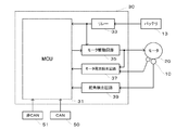
- a control unit (ECU) 30 for controlling the electric power steering apparatus is configured with a micro control unit (MCU) 31 as a basic component, and is supplied with electric power from the battery 13 and passes through an ignition key 11 and an ignition key. A signal is input.
- MCU micro control unit
- the control unit (ECU) 30 configured as described above calculates the current command value of the assist (steering assist) command based on the steering torque Th detected by the torque sensor 10 and the vehicle speed Vel detected by the vehicle speed sensor 12.
- the current supplied to the motor 20 is controlled by a voltage control command value Vref obtained by compensating the current command value.
- the steering angle sensor 14 is not essential and may not be provided, and the steering angle can be obtained from a rotational position sensor such as a resolver connected to a motor.
- control unit (ECU) 30 is connected to a CAN (Controller Area Network) 50 that transmits and receives various types of vehicle information, and the vehicle speed Vel can be received from the CAN 50.
- the control unit (ECU) 30 is also connected to a non-CAN 51 that exchanges communications other than the CAN 50, analog / digital signals, radio waves, and the like.
- the control unit (ECU) 30 as described above generally has a basic configuration as shown in FIG. 2, and in addition to the micro control unit (MCU) 31 having a central processing unit (CPU), a motor A drive circuit 35, a motor current detection circuit 37, a steering angle detection circuit 39, a power supply relay 33, and the like are provided.
- MCU micro control unit
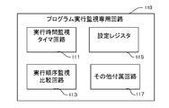
- the program execution monitoring dedicated circuit 110 of the present invention is mounted in the MCU 31 of the control unit 30 as described above.
- FIG. 3 shows a schematic configuration of the MCU 31.
- the MCU 31 includes a CPU 130, a ROM (including an EEPROM, etc.) 150, a RAM 170, A peripheral 190 and the like are provided through an interface and the like, and these are connected by a data bus, an instruction bus, and the like.
- the ROM 150 stores an electric power steering control program including a plurality of processes, control data, and the like, and the CPU 130 executes the control program to control the electric power steering.
- the RAM 170 also functions as a work memory when the CPU 130 operates.
- Registers, program counters, CPU status information, and the like are transmitted between the CPU 130 and the program execution monitoring dedicated circuit 110 of the present invention. Further, the program execution monitoring dedicated circuit 110 transmits information to the CPU 130. Signal lines for interrupt instructions and hardware (HW) alarms to external ports are connected.
- HW hardware
- the program execution monitoring dedicated circuit 110 of the present invention further includes an execution order monitoring / comparing circuit 113, an execution time monitoring timer circuit 111, a setting register 115, and other attached circuits 117. ing.
- the execution order monitoring / comparing circuit 113 is a circuit that monitors whether tasks (processes) executed by the CPU 130 by the control program are performed in order, and whether the processes are executed under a predetermined process. Whether or not the previous task is appropriate is monitored.
- execution time monitoring timer circuit 111 monitors whether or not each process has been executed after a time equal to or greater than a predetermined threshold predetermined for each process.
- the setting register 115 records setting information used for the operation of the program execution monitoring dedicated circuit 110 in advance.
- FIG. 5 shows an example of register setting for a certain process in the program execution monitoring dedicated circuit 110 inside the MCU 31.
- a time threshold is set.
- the process refers to a plurality of control procedures constituting a control program.
- the process is a torque control process for calculating a steering assist torque command value based on the steering torque T and the vehicle speed V, and based on the steering assist torque command value.
- the current control process for driving the steering assist motor 20 is included.
- Each process basically executes a plurality of processes periodically, and the number of processes varies from process to process.
- the setting register 115 as shown in FIG. 6, the type and execution order of processing normally performed by the program and the execution time threshold thereof, the type and execution order of processing when the program performs alternative processing, and the execution thereof are shown.
- the execution time threshold of the process in the case of performing the alternative process of FIG. 6 is set to half of the execution time threshold of the normal process, but the content of the alternative process and the execution time threshold of the alternative process Is an example and is not limited thereto. Therefore, a plurality of normal processes may be supplemented with one alternative process depending on circumstances, and the execution time threshold value can be set to be not limited to half the execution time threshold value of the normal process.
- Other accessory circuits 117 include hardware (HW) timers, timer counters, compare registers, etc., interrupt processing and HW alarm generation circuits, execution sequence and execution time read from the CPU 130, and whether or not alternative processing is performed.
- HW hardware
- a log register or the like for storing the information is provided as necessary.
- the execution monitoring of the control program and necessary substitution processing are performed by the following execution procedure.
- the execution order is monitored by a plurality of processes (1 to n) including a function pointer table or the like registered in advance in the setting register by the execution order monitoring / comparing circuit 113 in the program execution monitoring dedicated circuit 110.
- a function pointer table or the like registered in advance in the setting register by the execution order monitoring / comparing circuit 113 in the program execution monitoring dedicated circuit 110.
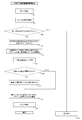
- the program execution monitoring dedicated circuit 110 reads the processing address of the instruction code transferred to the corresponding register of the CPU 130 from the register in the CPU 130 or the access information to the ROM 150 as shown in FIG. 7 (step S1). .
- the processing address registered in advance in the setting register 115 in the program execution monitoring dedicated circuit 110 is compared with the processing address of the read instruction code and the same processing address. Is stored as log information in the log register as to what execution order (1 to n) is in the processing address registered in the setting register 115 (step S2).
- step S3 it is detected from the log information in the log register whether or not the execution order of the processes up to the previous time is recorded. If the execution order is recorded, the process proceeds to the next step S4.
- next step S4 information indicating the order of execution of the process detected last time is extracted from the log information of the log register, and in the subsequent step S5, the execution order of the process detected this time is the process detected last time. It is determined whether or not the next execution order is applicable.
- step S5 If it is determined in step S5 that the execution order of the process detected this time corresponds to the execution order next to the process detected last time and there is no abnormality in the process order, the process returns to step S1. On the other hand, when it is determined that there is an abnormality in the processing order, the process proceeds to the next step S6 in which an HW alarm is generated or an alternative process is performed.
- the CPU 130 is interrupted, and as shown in FIG. 6, based on the current process order, the regular process or the alternative process corresponding to the order is performed, and the process being executed Depending on the importance of the process, such as returning the whole to the initial state and redoing the execution of a series of processes, or starting from the process immediately before the occurrence of an abnormality based on log information etc. It is possible to select an appropriate process.
- an error information log is recorded in the log register and the same error is detected many times.
- alternative processing such as skipping processing in which a failure has occurred. Then, after shifting to the alternative process and executing it as described above, the process shifts again to monitoring of the program execution order.
- the execution order monitoring / comparing circuit 113 in the program execution monitoring dedicated circuit 110 of the present invention executes the control program based on the start addresses (processing addresses) of the plurality of processes (1 to n).
- the order is monitored, in the program execution monitoring in the present invention, for example, the execution order of each process is read from the program counter of the CPU 130 and registered in the setting register in the program execution monitoring dedicated circuit 110 in advance.
- a configuration and method for monitoring the validity of selection of the process itself by comparing with the processing address may be adopted.
- each process constituting the control program is subdivided for each process, and each process (1 to n) is executed for monitoring the execution time.
- An execution time threshold is set and stored in the setting register 115.
- an alternative process is set for each of the above processes so as to be paired therewith, and an execution time threshold is also set for the alternative process. Stored.
- FIG. 8 shows a case where the execution time of the plurality of processes n (process n: where 1 ⁇ n ⁇ N) does not exceed a predetermined execution time threshold, that is, the CPU 130 executes the processes. It is the conceptual diagram which showed the measurement example when abnormality does not arise in time, and the operation
- the horizontal axis shows the flow of a plurality of processes
- FIG. 8 also shows the case where there are only N processes in one process and the process shifts to the same process in the next cycle.
- the vertical axis represents the program counter value or execution time that has elapsed for each process. For this reason, the upward slanting line indicated by a solid line for each process represents the passage of time for each process, and the chain line similarly indicated for each process indicates an execution time threshold set for each process. .
- each process n is started and monitoring of the execution time by the execution time monitoring timer circuit 111 is started (Start).
- the execution time is monitored using a timer in the program execution monitoring dedicated circuit.
- the time measurement may be performed by mutually converting the timer count value of the program execution monitoring circuit 110 or the real time calculation value based on the timer count value.
- the execution time monitoring timer circuit 111 measures the passage of the execution time and compares it with a preset execution time threshold for each process as described in FIGS.
- the elapsed time for each process (the solid line rising to the right in FIG. 8A), that is, the execution time, is the execution time threshold preset for each process (the horizontal chain line shown in FIG. 8A).
- the execution time monitoring by the execution time monitoring timer circuit 111 is stopped.
- the execution time monitoring dedicated circuit 110 can be automatically performed by the program execution monitoring dedicated circuit 110 based on preset information.
- setting information such as an execution time threshold value for each process is input to the setting register 115 and the like in advance, and can be read and used as necessary.
- the hardware timer of the circuit 110 and the CPU clock may be synchronized in advance as necessary.
- FIG. 9 is a diagram configured in the same manner as described above, but unlike the case of FIG. 8 above, a measurement example when an abnormality occurs in the execution time and the execution time monitoring timer of the present invention corresponding thereto
- FIG. 6 is a conceptual diagram showing the operation of a circuit 111.
- the execution time monitoring timer circuit 111 starts each process n and starts monitoring the execution time by the execution time monitoring timer circuit 111 ( Start).
- the execution time monitoring timer circuit 111 measures the passage of the execution time, compares the execution time with a preset execution time threshold for each process, and performs the elapsed time for each process. (A solid line rising to the right in FIG. 9) That is, it is monitored whether or not the execution time reaches a preset execution time threshold value (horizontal chain line shown in FIG. 9) for each process.
- the program execution monitoring dedicated circuit interrupts the occurrence of an abnormal execution time. Is notified to the CPU 130 and interrupt processing is performed.
- the interrupt process is a process executed by replacing the process determined that the abnormality has occurred with an alternative process. Therefore, for example, when the process 2 in FIG. 9 is taken as an example, as shown in FIG. 6, the execution time of the process 2 has reached 120 [ ⁇ S], and it is determined that there is an abnormality in the execution time. In this case, the process 2 is appropriately interrupted, and the alternative process of the process 2 is performed by interruption.
- the interrupt processing itself is processing by software.
- the process shifts to the next process 3 as shown in FIG. 9 and shifts to a normal monitoring state.
- the process in which the substitute process is performed is executed by replacing the process with the substitute process in the process of the next cycle. Therefore, for example, as shown in FIG. 9, for the process 2, in the next execution cycle of the process, an alternative process of the process 2 is performed from the beginning, and the program execution monitoring dedicated circuit 110 monitors the execution time. It is also possible to carry out based on an alternative process execution time threshold shown in FIG.
- the process N of the CPU 130 is not completed within the time set by the execution time threshold (when the execution time becomes equal to the execution time threshold). Is timed out because the timer of the execution time monitoring timer circuit 111 is not stopped, and interrupt processing is performed.
- FIG. 10 is a flowchart showing an outline of the flow of such interrupt processing.
- interrupt prohibition processing is performed (step S20). This is for preventing another interrupt from being instructed to the CPU 130 during the interrupt operation based on the instruction from the program execution monitoring dedicated circuit, and causing multiple interrupts.
- step S22 it is determined whether or not the process being interrupted is an alternative process. This is to eliminate the possibility that the process falls into an infinite loop by performing the same alternative process when the process being executed is an alternative process. Therefore, if it is determined by the above determination that the process being executed is an alternative process, the interrupt process is terminated as an abnormal end, and a signal for starting a hardware alarm or the like is output to the external port (step S30). . On the other hand, if it is determined that the process being executed is not an alternative process, the process proceeds to the next step S23.
- Step 23 is a process of rearranging the contents of the instruction code and function execution table of the CPU 130 so that the process being executed is replaced with an alternative process.
- the alternative process is set in advance for each process, and therefore recombination is performed based on the setting.
- step 24 the setting register 115 of the program execution monitoring dedicated circuit 110 is reset in order to monitor the execution time and order of the alternative processing. For this reason, information such as the processing address of the next processing after the processing being executed, the processing address of the alternative processing, and the alternative processing execution time threshold is recorded in the setting register 115 or the like for later reference. .
- step S25 the calculation value of process N is checked (step S25). This is to determine whether or not the calculated value of the process N that has performed the substitute process is abnormal (step S26). The determination is based on a predetermined value that is set in advance as the calculated value of the process N based on the substitute process. It is performed depending on whether or not it is within the threshold value. If it is determined that there is an abnormality in the calculation value of the process N, the calculation value of the process N is replaced with a default value (step S27), and it is determined that there is no abnormality in the calculation value of the process N. In this case, the process proceeds to step S28.
- step S28 the program counter of the CPU 130 is set at the head of the process N + 1, and an instruction for permitting another interrupt prohibited in step S20 is issued (step 29). The interrupt by the program execution monitoring circuit is terminated. .
- the execution time is monitored as described above, and if the execution time of the process N exceeds a predetermined execution time threshold, the execution of the program is stopped and the control is performed without stopping the execution of the program. It is possible to continue.
- the execution monitoring of the program is performed by a dedicated program execution monitoring circuit mounted inside the MCU. The circuit is based on information such as an instruction fetch address from the instruction bus and a program counter in the CPU. It is possible to know which program is currently being executed, and by using this, the timer in the dedicated circuit is used if the start addresses of processing 1 to N and the upper limit threshold of the execution time are registered in advance in the setting register. The execution time can be measured almost automatically.
- the execution time can be monitored by taking into account processing delays caused by other interrupts. Therefore, when general-purpose interrupt processing is used when acquiring sensor information and the interrupt processing time is not to be included in the processing N, the hardware acquires the CPU information and executes the timer of the execution time during the interrupt. A mechanism for stopping (maintaining) the counter may be implemented, or during the interruption, it may be possible to select whether to stop or continue the timer counter.
- the execution time is measured from the process N to the process N + 1.
- the execution time of the process N only or the process N and the process N + 2 are not continuous.
- “end address” may be added to the register in the program execution monitoring dedicated circuit in addition to the start address of process N, and the measurement may be terminated when the “end address” is reached.
- the setting register in order to measure the execution time in the interrupt processing, it is possible to configure the setting register so that it can be divided into normal processing (periodic processing) and interrupt processing.
- the abnormal execution state of the control program for the in-vehicle electronic device as described above is monitored, and the abnormal state is detected. In such a case, it is possible to continue the above control by performing an alternative process.
- control apparatus and method for an in-vehicle electronic device according to the present invention when used, for example, for control of an electric power steering apparatus, the control apparatus continues even if it is determined that an abnormality has occurred in the control apparatus. Steering assist can be performed.
Landscapes
- Engineering & Computer Science (AREA)
- Theoretical Computer Science (AREA)
- Physics & Mathematics (AREA)
- General Physics & Mathematics (AREA)
- General Engineering & Computer Science (AREA)
- Chemical & Material Sciences (AREA)
- Combustion & Propulsion (AREA)
- Transportation (AREA)
- Mechanical Engineering (AREA)
- Quality & Reliability (AREA)
- Software Systems (AREA)
- Automation & Control Theory (AREA)
- Power Steering Mechanism (AREA)
- Steering Control In Accordance With Driving Conditions (AREA)
- Debugging And Monitoring (AREA)
Abstract
Description
2 コラム軸(ステアリングシャフト、ハンドル軸)
3 減速機構
4a 4b ユニバーサルジョイント
5 ピニオンラック機構
6a 6b タイロッド
7a 7b ハブユニット
8L 8R 操向車輪
10 トルクセンサ
11 イグニションキー
12 車速センサ
13 バッテリ
14 舵角センサ
20 モータ
30 コントロールユニット(ECU)
31 マイクロコントロールユニット(MCU)
33 リレー
35 モータ駆動回路
37 モータ電流検出回路
39 舵角検出回路
110 プログラム実行監視専用回路
111 実行時間監視タイマ回路
113 実行順序監視比較回路
115 設定レジスタ
117 その他の付属回路
130 CPU
150 ROM
170 RAM
190 ペリフェラル
Claims (10)
- 車載用電子機器の制御装置であって、前記制御装置には、前記車載用電子機器の制御プログラムが実行するタスクの実行順序と実行時間とを監視するプログラム実行監視専用回路を実装したことを特徴とする車載用電子機器の制御装置。
- 前記プログラム実行監視専用回路は、前記タスクの実行順序が予め設定された順序と異なる場合、又は/及び、前記タスクの実行時間が予め設定された閾値を超えた場合に、予め設定された信号を出力する請求項1に記載の車載用電子機器の制御装置。
- 前記予め設定された信号が出力された場合には、代替処理を行い、前記車載用電子機器の制御を継続することが可能な請求項1又は2に記載の車載用電子機器の制御装置。
- 前記プログラム実行監視専用回路は、車載用MCUに備えられている請求項1乃至3のいずれか1項に記載の車載用電子機器の制御装置。
- 前記車載用電子機器は電動パワーステアリング装置である請求項1乃至4のいずれか1項に記載の車載用電子機器の制御装置。
- 車載用電子機器の制御プログラムが実行するタスクの実行順序と実行時間とを監視するプログラム実行監視専用回路を用いて、前記車載用電子機器の制御プログラムの実行状態を監視することを特徴とする車載用電子機器の制御方法。
- 前記車載用電子機器の制御プログラムの実行状態の監視は、前記制御プログラムが実行する前記タスクの実行順序が予め設定された順序と異なる場合、又は/及び、前記タスクの実行時間が予め設定された閾値を超えた場合に、予め設定された信号を出力することにより行う、請求項6に記載の車載用電子機器の制御方法。
- 前記予め設定された信号が出力された場合には、代替処理を行うことにより、前記車載用電子機器の制御を継続することが可能な請求項6又は7に記載の車載用電子機器の制御方法。
- 前記プログラム実行監視専用回路は、車載用MCUに備えられている請求項6乃至8のいずれか1項に記載の車載用電子機器の制御方法。
- 前記車載用電子機器は電動パワーステアリング装置である請求項6乃至9のいずれか1項に記載の車載用電子機器の制御方法。
Priority Applications (21)
| Application Number | Priority Date | Filing Date | Title |
|---|---|---|---|
| JP2015541355A JP5846342B1 (ja) | 2014-09-25 | 2014-09-25 | 車載用電子機器の制御装置及び制御方法 |
| BR112016003514-3A BR112016003514A2 (pt) | 2014-09-25 | 2014-09-25 | aparelho de controle e método de controle de equipamentos eletrônicos instalados em veículos |
| PCT/JP2014/075396 WO2016046931A1 (ja) | 2014-09-25 | 2014-09-25 | 車載用電子機器の制御装置及び制御方法 |
| US14/782,037 US9796415B2 (en) | 2014-09-25 | 2014-09-25 | Control apparatus and control method of on-vehicle electronic equipment |
| CN201480016866.XA CN105980214B (zh) | 2014-09-25 | 2014-09-25 | 车载用电子设备的控制装置和控制方法 |
| EP14886669.2A EP3023304B1 (en) | 2014-09-25 | 2014-09-25 | Vehicle-mounted electronic device control device and control method |
| EP15843261.7A EP3199407B1 (en) | 2014-09-25 | 2015-09-18 | Control device and control method for on-vehicle electronic apparatus |
| PCT/JP2015/076625 WO2016047575A1 (ja) | 2014-09-25 | 2015-09-18 | 車載用電子機器の制御装置及び制御方法 |
| PCT/JP2015/076626 WO2016047576A1 (ja) | 2014-09-25 | 2015-09-18 | 車載用電子機器の制御装置及び制御方法 |
| CN201580051307.7A CN106794810B (zh) | 2014-09-25 | 2015-09-18 | 车载用电子设备的控制装置以及控制方法 |
| EP15844897.7A EP3199408A4 (en) | 2014-09-25 | 2015-09-18 | Control device and control method for on-vehicle electronic apparatus |
| US15/312,275 US9889881B2 (en) | 2014-09-25 | 2015-09-18 | Control apparatus and control method of on-vehicle electronic equipment |
| CN201580050289.0A CN106794809B (zh) | 2014-09-25 | 2015-09-18 | 车载用电子设备的控制装置以及控制方法 |
| US15/312,306 US10017205B2 (en) | 2014-09-25 | 2015-09-18 | Control apparatus and control method of on-vehicle electronic equipment |
| JP2016550165A JP6164374B2 (ja) | 2014-09-25 | 2015-09-18 | 車載用電子機器の制御装置及び制御方法 |
| JP2016550164A JP6164373B2 (ja) | 2014-09-25 | 2015-09-18 | 車載用電子機器の制御装置及び制御方法 |
| JP2017121195A JP6350724B2 (ja) | 2014-09-25 | 2017-06-21 | 車載用電子機器の制御装置及び制御方法 |
| JP2017121192A JP6311828B2 (ja) | 2014-09-25 | 2017-06-21 | 車載用電子機器の制御装置及び制御方法 |
| JP2017121194A JP6311829B2 (ja) | 2014-09-25 | 2017-06-21 | 車載用電子機器の制御装置及び制御方法 |
| JP2017121186A JP6311827B2 (ja) | 2014-09-25 | 2017-06-21 | 車載用電子機器の制御装置及び制御方法 |
| JP2017121190A JP6350723B2 (ja) | 2014-09-25 | 2017-06-21 | 車載用電子機器の制御装置及び制御方法 |
Applications Claiming Priority (1)
| Application Number | Priority Date | Filing Date | Title |
|---|---|---|---|
| PCT/JP2014/075396 WO2016046931A1 (ja) | 2014-09-25 | 2014-09-25 | 車載用電子機器の制御装置及び制御方法 |
Publications (1)
| Publication Number | Publication Date |
|---|---|
| WO2016046931A1 true WO2016046931A1 (ja) | 2016-03-31 |
Family
ID=55169204
Family Applications (1)
| Application Number | Title | Priority Date | Filing Date |
|---|---|---|---|
| PCT/JP2014/075396 WO2016046931A1 (ja) | 2014-09-25 | 2014-09-25 | 車載用電子機器の制御装置及び制御方法 |
Country Status (6)
| Country | Link |
|---|---|
| US (1) | US9796415B2 (ja) |
| EP (1) | EP3023304B1 (ja) |
| JP (1) | JP5846342B1 (ja) |
| CN (1) | CN105980214B (ja) |
| BR (1) | BR112016003514A2 (ja) |
| WO (1) | WO2016046931A1 (ja) |
Cited By (3)
| Publication number | Priority date | Publication date | Assignee | Title |
|---|---|---|---|---|
| KR20200068702A (ko) * | 2017-10-10 | 2020-06-15 | 크로노-세이프 | 실시간 작업들 간에 저지연 통신을 보장하는 시퀀싱 계획들을 실행하는 방법 |
| JP7109621B1 (ja) | 2021-05-06 | 2022-07-29 | 三菱電機株式会社 | 制御システム |
| WO2022180893A1 (ja) * | 2021-02-24 | 2022-09-01 | 日立Astemo株式会社 | 制御装置及び制御方法 |
Families Citing this family (8)
| Publication number | Priority date | Publication date | Assignee | Title |
|---|---|---|---|---|
| US9889881B2 (en) * | 2014-09-25 | 2018-02-13 | Nsk Ltd. | Control apparatus and control method of on-vehicle electronic equipment |
| US10017205B2 (en) * | 2014-09-25 | 2018-07-10 | Nsk Ltd. | Control apparatus and control method of on-vehicle electronic equipment |
| JP6428980B2 (ja) * | 2016-09-16 | 2018-11-28 | 日本精工株式会社 | 電動パワーステアリング装置 |
| FR3083884B1 (fr) * | 2018-07-16 | 2021-06-11 | Airbus Helicopters | Procede de gestion d'un systeme de pilotage automatique equipant un aeronef |
| JP7419658B2 (ja) * | 2019-02-25 | 2024-01-23 | 株式会社デンソー | センター装置、データ配信システム、制限実施プログラム及び制限実施方法 |
| JP6889196B2 (ja) * | 2019-03-15 | 2021-06-18 | 矢崎総業株式会社 | 車両用通信システム |
| DE112019007937T5 (de) * | 2019-12-04 | 2022-10-27 | Mitsubishi Electric Corporation | Fahrzeug-steuerungseinrichtung |
| JP2024014071A (ja) * | 2022-07-21 | 2024-02-01 | 株式会社ジェイテクト | 車両用制御装置及び車両用制御方法 |
Citations (5)
| Publication number | Priority date | Publication date | Assignee | Title |
|---|---|---|---|---|
| JPH06324914A (ja) * | 1993-05-13 | 1994-11-25 | Fuji Electric Co Ltd | コンピュータの暴走検出方法 |
| JPH10198584A (ja) * | 1997-01-14 | 1998-07-31 | Nippon Steel Corp | アプリケーションソフトウェアの異常監視装置 |
| JP2001175497A (ja) * | 1999-12-14 | 2001-06-29 | Hyundai Motor Co Ltd | ロジック診断方法 |
| JP2006090356A (ja) | 2004-09-21 | 2006-04-06 | Denso Corp | 車両制御装置、および処理負荷制御プログラム。 |
| JP2009113618A (ja) | 2007-11-06 | 2009-05-28 | Nsk Ltd | 電動パワーステアリング装置 |
Family Cites Families (7)
| Publication number | Priority date | Publication date | Assignee | Title |
|---|---|---|---|---|
| GB1312504A (en) * | 1970-05-20 | 1973-04-04 | Ibm | Control unit for serial data storage apparatus |
| US7028819B2 (en) * | 1996-02-21 | 2006-04-18 | Hitachi, Ltd. | Device and method for supplying power to a vehicle, semi-conductor circuit device for use in the same and collective wiring device for a vehicle or an automobile |
| JP4037617B2 (ja) * | 2001-03-16 | 2008-01-23 | 株式会社東芝 | 欠陥検索方法 |
| US6952795B2 (en) * | 2001-09-24 | 2005-10-04 | Motorola, Inc. | Method and apparatus for verifying the integrity of control module operation |
| JP5267186B2 (ja) * | 2009-02-13 | 2013-08-21 | 日本精工株式会社 | 電動パワーステアリング装置 |
| JP5569752B2 (ja) | 2011-12-08 | 2014-08-13 | 株式会社デンソー | 電子制御装置、および、これを用いた電動パワーステアリング装置 |
| JP5853691B2 (ja) * | 2011-12-28 | 2016-02-09 | アイシン・エィ・ダブリュ株式会社 | 車両用制御装置および方法 |
-
2014
- 2014-09-25 JP JP2015541355A patent/JP5846342B1/ja not_active Expired - Fee Related
- 2014-09-25 BR BR112016003514-3A patent/BR112016003514A2/pt not_active Application Discontinuation
- 2014-09-25 CN CN201480016866.XA patent/CN105980214B/zh not_active Expired - Fee Related
- 2014-09-25 US US14/782,037 patent/US9796415B2/en not_active Expired - Fee Related
- 2014-09-25 EP EP14886669.2A patent/EP3023304B1/en not_active Not-in-force
- 2014-09-25 WO PCT/JP2014/075396 patent/WO2016046931A1/ja active Application Filing
Patent Citations (5)
| Publication number | Priority date | Publication date | Assignee | Title |
|---|---|---|---|---|
| JPH06324914A (ja) * | 1993-05-13 | 1994-11-25 | Fuji Electric Co Ltd | コンピュータの暴走検出方法 |
| JPH10198584A (ja) * | 1997-01-14 | 1998-07-31 | Nippon Steel Corp | アプリケーションソフトウェアの異常監視装置 |
| JP2001175497A (ja) * | 1999-12-14 | 2001-06-29 | Hyundai Motor Co Ltd | ロジック診断方法 |
| JP2006090356A (ja) | 2004-09-21 | 2006-04-06 | Denso Corp | 車両制御装置、および処理負荷制御プログラム。 |
| JP2009113618A (ja) | 2007-11-06 | 2009-05-28 | Nsk Ltd | 電動パワーステアリング装置 |
Non-Patent Citations (1)
| Title |
|---|
| See also references of EP3023304A4 |
Cited By (8)
| Publication number | Priority date | Publication date | Assignee | Title |
|---|---|---|---|---|
| KR20200068702A (ko) * | 2017-10-10 | 2020-06-15 | 크로노-세이프 | 실시간 작업들 간에 저지연 통신을 보장하는 시퀀싱 계획들을 실행하는 방법 |
| JP2020537269A (ja) * | 2017-10-10 | 2020-12-17 | クロノ−セーフ | リアルタイムタスク間の低レイテンシ通信を保証する順序付け計画を実行するための方法 |
| JP7266590B2 (ja) | 2017-10-10 | 2023-04-28 | クロノ-セーフ | リアルタイムタスク間の低レイテンシ通信を保証する順序付け計画を実行するための方法 |
| KR102602151B1 (ko) | 2017-10-10 | 2023-11-15 | 크로노-세이프 | 실시간 작업들 간에 저지연 통신을 보장하는 시퀀싱 계획들을 실행하는 방법 |
| WO2022180893A1 (ja) * | 2021-02-24 | 2022-09-01 | 日立Astemo株式会社 | 制御装置及び制御方法 |
| JP7498845B2 (ja) | 2021-02-24 | 2024-06-12 | 日立Astemo株式会社 | 制御装置及び制御方法 |
| JP7109621B1 (ja) | 2021-05-06 | 2022-07-29 | 三菱電機株式会社 | 制御システム |
| JP2022172517A (ja) * | 2021-05-06 | 2022-11-17 | 三菱電機株式会社 | 制御システム |
Also Published As
| Publication number | Publication date |
|---|---|
| JP5846342B1 (ja) | 2016-01-20 |
| US20170197655A1 (en) | 2017-07-13 |
| CN105980214B (zh) | 2018-01-30 |
| CN105980214A (zh) | 2016-09-28 |
| EP3023304B1 (en) | 2018-01-31 |
| EP3023304A4 (en) | 2017-03-29 |
| BR112016003514A2 (pt) | 2021-04-13 |
| JPWO2016046931A1 (ja) | 2017-04-27 |
| EP3023304A1 (en) | 2016-05-25 |
| US9796415B2 (en) | 2017-10-24 |
Similar Documents
| Publication | Publication Date | Title |
|---|---|---|
| JP6311828B2 (ja) | 車載用電子機器の制御装置及び制御方法 | |
| JP5846342B1 (ja) | 車載用電子機器の制御装置及び制御方法 | |
| JP6350724B2 (ja) | 車載用電子機器の制御装置及び制御方法 | |
| JP2009113618A (ja) | 電動パワーステアリング装置 | |
| JP6311693B2 (ja) | 車載用電子機器の制御装置及び制御方法 | |
| JP6020765B2 (ja) | 車載用電子機器の制御装置及び制御方法 | |
| JP6540227B2 (ja) | 車両用制御装置 | |
| JP6481788B2 (ja) | 車載用電子機器の制御装置及び制御方法 | |
| JP6481789B2 (ja) | 車載用電子機器の制御装置及び制御方法 |
Legal Events
| Date | Code | Title | Description |
|---|---|---|---|
| ENP | Entry into the national phase |
Ref document number: 2015541355 Country of ref document: JP Kind code of ref document: A |
|
| WWE | Wipo information: entry into national phase |
Ref document number: 2014886669 Country of ref document: EP |
|
| WWE | Wipo information: entry into national phase |
Ref document number: 14782037 Country of ref document: US |
|
| 121 | Ep: the epo has been informed by wipo that ep was designated in this application |
Ref document number: 14886669 Country of ref document: EP Kind code of ref document: A1 |
|
| NENP | Non-entry into the national phase |
Ref country code: DE |
|
| REG | Reference to national code |
Ref country code: BR Ref legal event code: B01A Ref document number: 112016003514 Country of ref document: BR |
|
| REG | Reference to national code |
Ref country code: BR Ref legal event code: B01E Ref document number: 112016003514 Country of ref document: BR Free format text: APRESENTE O COMPLEMENTO DO TEXTO EM PORTUGUES, ADAPTADO A NORMAVIGENTE, DO PEDIDO CONFORME DEPOSITO INTERNACIONAL INICIAL (RESUMO),CONFORME DETERMINA O ATO NORMATIVO 128/97 NO ITEM 9.2.1 |
|
| REG | Reference to national code |
Ref country code: BR Ref legal event code: B01Y Ref document number: 112016003514 Country of ref document: BR Free format text: ANULADA A PUBLICACAO CODIGO 1.5 NA RPI NO 2501 DE 11/12/2018 POR TER SIDO INDEVIDA. |
|
| ENP | Entry into the national phase |
Ref document number: 112016003514 Country of ref document: BR Kind code of ref document: A2 Effective date: 20160219 |
|
| REG | Reference to national code |
Ref country code: BR Ref legal event code: B01E Ref document number: 112016003514 Country of ref document: BR Kind code of ref document: A2 Free format text: APRESENTE O RESUMO DO PEDIDO EM 60 DIAS |
|
| REG | Reference to national code |
Ref country code: BR Ref legal event code: B01Y Ref document number: 112016003514 Country of ref document: BR Kind code of ref document: A2 Free format text: ANULADA A PUBLICACAO CODIGO 1.5 NA RPI NO 2600 DE 03/11/2020 POR TER SIDO INDEVIDA. |
|
| ENP | Entry into the national phase |
Ref document number: 112016003514 Country of ref document: BR Kind code of ref document: A2 Effective date: 20160219 |