WO2016030941A1 - 電気車制御装置 - Google Patents
電気車制御装置 Download PDFInfo
- Publication number
- WO2016030941A1 WO2016030941A1 PCT/JP2014/072145 JP2014072145W WO2016030941A1 WO 2016030941 A1 WO2016030941 A1 WO 2016030941A1 JP 2014072145 W JP2014072145 W JP 2014072145W WO 2016030941 A1 WO2016030941 A1 WO 2016030941A1
- Authority
- WO
- WIPO (PCT)
- Prior art keywords
- control
- overvoltage
- electric vehicle
- control device
- control system
- Prior art date
Links
Images


Classifications
-
- B—PERFORMING OPERATIONS; TRANSPORTING
- B60—VEHICLES IN GENERAL
- B60L—PROPULSION OF ELECTRICALLY-PROPELLED VEHICLES; SUPPLYING ELECTRIC POWER FOR AUXILIARY EQUIPMENT OF ELECTRICALLY-PROPELLED VEHICLES; ELECTRODYNAMIC BRAKE SYSTEMS FOR VEHICLES IN GENERAL; MAGNETIC SUSPENSION OR LEVITATION FOR VEHICLES; MONITORING OPERATING VARIABLES OF ELECTRICALLY-PROPELLED VEHICLES; ELECTRIC SAFETY DEVICES FOR ELECTRICALLY-PROPELLED VEHICLES
- B60L3/00—Electric devices on electrically-propelled vehicles for safety purposes; Monitoring operating variables, e.g. speed, deceleration or energy consumption
- B60L3/04—Cutting off the power supply under fault conditions
-
- B—PERFORMING OPERATIONS; TRANSPORTING
- B60—VEHICLES IN GENERAL
- B60L—PROPULSION OF ELECTRICALLY-PROPELLED VEHICLES; SUPPLYING ELECTRIC POWER FOR AUXILIARY EQUIPMENT OF ELECTRICALLY-PROPELLED VEHICLES; ELECTRODYNAMIC BRAKE SYSTEMS FOR VEHICLES IN GENERAL; MAGNETIC SUSPENSION OR LEVITATION FOR VEHICLES; MONITORING OPERATING VARIABLES OF ELECTRICALLY-PROPELLED VEHICLES; ELECTRIC SAFETY DEVICES FOR ELECTRICALLY-PROPELLED VEHICLES
- B60L15/00—Methods, circuits, or devices for controlling the traction-motor speed of electrically-propelled vehicles
- B60L15/10—Methods, circuits, or devices for controlling the traction-motor speed of electrically-propelled vehicles for automatic control superimposed on human control to limit the acceleration of the vehicle, e.g. to prevent excessive motor current
-
- B—PERFORMING OPERATIONS; TRANSPORTING
- B60—VEHICLES IN GENERAL
- B60L—PROPULSION OF ELECTRICALLY-PROPELLED VEHICLES; SUPPLYING ELECTRIC POWER FOR AUXILIARY EQUIPMENT OF ELECTRICALLY-PROPELLED VEHICLES; ELECTRODYNAMIC BRAKE SYSTEMS FOR VEHICLES IN GENERAL; MAGNETIC SUSPENSION OR LEVITATION FOR VEHICLES; MONITORING OPERATING VARIABLES OF ELECTRICALLY-PROPELLED VEHICLES; ELECTRIC SAFETY DEVICES FOR ELECTRICALLY-PROPELLED VEHICLES
- B60L15/00—Methods, circuits, or devices for controlling the traction-motor speed of electrically-propelled vehicles
- B60L15/20—Methods, circuits, or devices for controlling the traction-motor speed of electrically-propelled vehicles for control of the vehicle or its driving motor to achieve a desired performance, e.g. speed, torque, programmed variation of speed
- B60L15/2009—Methods, circuits, or devices for controlling the traction-motor speed of electrically-propelled vehicles for control of the vehicle or its driving motor to achieve a desired performance, e.g. speed, torque, programmed variation of speed for braking
-
- B—PERFORMING OPERATIONS; TRANSPORTING
- B60—VEHICLES IN GENERAL
- B60L—PROPULSION OF ELECTRICALLY-PROPELLED VEHICLES; SUPPLYING ELECTRIC POWER FOR AUXILIARY EQUIPMENT OF ELECTRICALLY-PROPELLED VEHICLES; ELECTRODYNAMIC BRAKE SYSTEMS FOR VEHICLES IN GENERAL; MAGNETIC SUSPENSION OR LEVITATION FOR VEHICLES; MONITORING OPERATING VARIABLES OF ELECTRICALLY-PROPELLED VEHICLES; ELECTRIC SAFETY DEVICES FOR ELECTRICALLY-PROPELLED VEHICLES
- B60L15/00—Methods, circuits, or devices for controlling the traction-motor speed of electrically-propelled vehicles
- B60L15/20—Methods, circuits, or devices for controlling the traction-motor speed of electrically-propelled vehicles for control of the vehicle or its driving motor to achieve a desired performance, e.g. speed, torque, programmed variation of speed
- B60L15/22—Methods, circuits, or devices for controlling the traction-motor speed of electrically-propelled vehicles for control of the vehicle or its driving motor to achieve a desired performance, e.g. speed, torque, programmed variation of speed with sequential operation of interdependent switches, e.g. relays, contactors, programme drum
-
- B—PERFORMING OPERATIONS; TRANSPORTING
- B60—VEHICLES IN GENERAL
- B60L—PROPULSION OF ELECTRICALLY-PROPELLED VEHICLES; SUPPLYING ELECTRIC POWER FOR AUXILIARY EQUIPMENT OF ELECTRICALLY-PROPELLED VEHICLES; ELECTRODYNAMIC BRAKE SYSTEMS FOR VEHICLES IN GENERAL; MAGNETIC SUSPENSION OR LEVITATION FOR VEHICLES; MONITORING OPERATING VARIABLES OF ELECTRICALLY-PROPELLED VEHICLES; ELECTRIC SAFETY DEVICES FOR ELECTRICALLY-PROPELLED VEHICLES
- B60L3/00—Electric devices on electrically-propelled vehicles for safety purposes; Monitoring operating variables, e.g. speed, deceleration or energy consumption
- B60L3/0023—Detecting, eliminating, remedying or compensating for drive train abnormalities, e.g. failures within the drive train
- B60L3/0076—Detecting, eliminating, remedying or compensating for drive train abnormalities, e.g. failures within the drive train relating to braking
-
- B—PERFORMING OPERATIONS; TRANSPORTING
- B60—VEHICLES IN GENERAL
- B60L—PROPULSION OF ELECTRICALLY-PROPELLED VEHICLES; SUPPLYING ELECTRIC POWER FOR AUXILIARY EQUIPMENT OF ELECTRICALLY-PROPELLED VEHICLES; ELECTRODYNAMIC BRAKE SYSTEMS FOR VEHICLES IN GENERAL; MAGNETIC SUSPENSION OR LEVITATION FOR VEHICLES; MONITORING OPERATING VARIABLES OF ELECTRICALLY-PROPELLED VEHICLES; ELECTRIC SAFETY DEVICES FOR ELECTRICALLY-PROPELLED VEHICLES
- B60L3/00—Electric devices on electrically-propelled vehicles for safety purposes; Monitoring operating variables, e.g. speed, deceleration or energy consumption
- B60L3/12—Recording operating variables ; Monitoring of operating variables
-
- B—PERFORMING OPERATIONS; TRANSPORTING
- B60—VEHICLES IN GENERAL
- B60L—PROPULSION OF ELECTRICALLY-PROPELLED VEHICLES; SUPPLYING ELECTRIC POWER FOR AUXILIARY EQUIPMENT OF ELECTRICALLY-PROPELLED VEHICLES; ELECTRODYNAMIC BRAKE SYSTEMS FOR VEHICLES IN GENERAL; MAGNETIC SUSPENSION OR LEVITATION FOR VEHICLES; MONITORING OPERATING VARIABLES OF ELECTRICALLY-PROPELLED VEHICLES; ELECTRIC SAFETY DEVICES FOR ELECTRICALLY-PROPELLED VEHICLES
- B60L7/00—Electrodynamic brake systems for vehicles in general
- B60L7/02—Dynamic electric resistor braking
- B60L7/04—Dynamic electric resistor braking for vehicles propelled by dc motors
-
- B—PERFORMING OPERATIONS; TRANSPORTING
- B60—VEHICLES IN GENERAL
- B60L—PROPULSION OF ELECTRICALLY-PROPELLED VEHICLES; SUPPLYING ELECTRIC POWER FOR AUXILIARY EQUIPMENT OF ELECTRICALLY-PROPELLED VEHICLES; ELECTRODYNAMIC BRAKE SYSTEMS FOR VEHICLES IN GENERAL; MAGNETIC SUSPENSION OR LEVITATION FOR VEHICLES; MONITORING OPERATING VARIABLES OF ELECTRICALLY-PROPELLED VEHICLES; ELECTRIC SAFETY DEVICES FOR ELECTRICALLY-PROPELLED VEHICLES
- B60L7/00—Electrodynamic brake systems for vehicles in general
- B60L7/02—Dynamic electric resistor braking
- B60L7/08—Controlling the braking effect
-
- B—PERFORMING OPERATIONS; TRANSPORTING
- B60—VEHICLES IN GENERAL
- B60L—PROPULSION OF ELECTRICALLY-PROPELLED VEHICLES; SUPPLYING ELECTRIC POWER FOR AUXILIARY EQUIPMENT OF ELECTRICALLY-PROPELLED VEHICLES; ELECTRODYNAMIC BRAKE SYSTEMS FOR VEHICLES IN GENERAL; MAGNETIC SUSPENSION OR LEVITATION FOR VEHICLES; MONITORING OPERATING VARIABLES OF ELECTRICALLY-PROPELLED VEHICLES; ELECTRIC SAFETY DEVICES FOR ELECTRICALLY-PROPELLED VEHICLES
- B60L7/00—Electrodynamic brake systems for vehicles in general
- B60L7/22—Dynamic electric resistor braking, combined with dynamic electric regenerative braking
-
- B—PERFORMING OPERATIONS; TRANSPORTING
- B60—VEHICLES IN GENERAL
- B60L—PROPULSION OF ELECTRICALLY-PROPELLED VEHICLES; SUPPLYING ELECTRIC POWER FOR AUXILIARY EQUIPMENT OF ELECTRICALLY-PROPELLED VEHICLES; ELECTRODYNAMIC BRAKE SYSTEMS FOR VEHICLES IN GENERAL; MAGNETIC SUSPENSION OR LEVITATION FOR VEHICLES; MONITORING OPERATING VARIABLES OF ELECTRICALLY-PROPELLED VEHICLES; ELECTRIC SAFETY DEVICES FOR ELECTRICALLY-PROPELLED VEHICLES
- B60L9/00—Electric propulsion with power supply external to the vehicle
- B60L9/02—Electric propulsion with power supply external to the vehicle using dc motors
- B60L9/04—Electric propulsion with power supply external to the vehicle using dc motors fed from dc supply lines
-
- H—ELECTRICITY
- H02—GENERATION; CONVERSION OR DISTRIBUTION OF ELECTRIC POWER
- H02P—CONTROL OR REGULATION OF ELECTRIC MOTORS, ELECTRIC GENERATORS OR DYNAMO-ELECTRIC CONVERTERS; CONTROLLING TRANSFORMERS, REACTORS OR CHOKE COILS
- H02P3/00—Arrangements for stopping or slowing electric motors, generators, or dynamo-electric converters
- H02P3/06—Arrangements for stopping or slowing electric motors, generators, or dynamo-electric converters for stopping or slowing an individual dynamo-electric motor or dynamo-electric converter
- H02P3/08—Arrangements for stopping or slowing electric motors, generators, or dynamo-electric converters for stopping or slowing an individual dynamo-electric motor or dynamo-electric converter for stopping or slowing a dc motor
- H02P3/12—Arrangements for stopping or slowing electric motors, generators, or dynamo-electric converters for stopping or slowing an individual dynamo-electric motor or dynamo-electric converter for stopping or slowing a dc motor by short-circuit or resistive braking
-
- H—ELECTRICITY
- H02—GENERATION; CONVERSION OR DISTRIBUTION OF ELECTRIC POWER
- H02P—CONTROL OR REGULATION OF ELECTRIC MOTORS, ELECTRIC GENERATORS OR DYNAMO-ELECTRIC CONVERTERS; CONTROLLING TRANSFORMERS, REACTORS OR CHOKE COILS
- H02P3/00—Arrangements for stopping or slowing electric motors, generators, or dynamo-electric converters
- H02P3/06—Arrangements for stopping or slowing electric motors, generators, or dynamo-electric converters for stopping or slowing an individual dynamo-electric motor or dynamo-electric converter
- H02P3/18—Arrangements for stopping or slowing electric motors, generators, or dynamo-electric converters for stopping or slowing an individual dynamo-electric motor or dynamo-electric converter for stopping or slowing an ac motor
- H02P3/22—Arrangements for stopping or slowing electric motors, generators, or dynamo-electric converters for stopping or slowing an individual dynamo-electric motor or dynamo-electric converter for stopping or slowing an ac motor by short-circuit or resistive braking
-
- B—PERFORMING OPERATIONS; TRANSPORTING
- B60—VEHICLES IN GENERAL
- B60L—PROPULSION OF ELECTRICALLY-PROPELLED VEHICLES; SUPPLYING ELECTRIC POWER FOR AUXILIARY EQUIPMENT OF ELECTRICALLY-PROPELLED VEHICLES; ELECTRODYNAMIC BRAKE SYSTEMS FOR VEHICLES IN GENERAL; MAGNETIC SUSPENSION OR LEVITATION FOR VEHICLES; MONITORING OPERATING VARIABLES OF ELECTRICALLY-PROPELLED VEHICLES; ELECTRIC SAFETY DEVICES FOR ELECTRICALLY-PROPELLED VEHICLES
- B60L2200/00—Type of vehicles
- B60L2200/26—Rail vehicles
-
- B—PERFORMING OPERATIONS; TRANSPORTING
- B60—VEHICLES IN GENERAL
- B60L—PROPULSION OF ELECTRICALLY-PROPELLED VEHICLES; SUPPLYING ELECTRIC POWER FOR AUXILIARY EQUIPMENT OF ELECTRICALLY-PROPELLED VEHICLES; ELECTRODYNAMIC BRAKE SYSTEMS FOR VEHICLES IN GENERAL; MAGNETIC SUSPENSION OR LEVITATION FOR VEHICLES; MONITORING OPERATING VARIABLES OF ELECTRICALLY-PROPELLED VEHICLES; ELECTRIC SAFETY DEVICES FOR ELECTRICALLY-PROPELLED VEHICLES
- B60L2240/00—Control parameters of input or output; Target parameters
- B60L2240/40—Drive Train control parameters
- B60L2240/52—Drive Train control parameters related to converters
- B60L2240/526—Operating parameters
-
- B—PERFORMING OPERATIONS; TRANSPORTING
- B60—VEHICLES IN GENERAL
- B60L—PROPULSION OF ELECTRICALLY-PROPELLED VEHICLES; SUPPLYING ELECTRIC POWER FOR AUXILIARY EQUIPMENT OF ELECTRICALLY-PROPELLED VEHICLES; ELECTRODYNAMIC BRAKE SYSTEMS FOR VEHICLES IN GENERAL; MAGNETIC SUSPENSION OR LEVITATION FOR VEHICLES; MONITORING OPERATING VARIABLES OF ELECTRICALLY-PROPELLED VEHICLES; ELECTRIC SAFETY DEVICES FOR ELECTRICALLY-PROPELLED VEHICLES
- B60L2240/00—Control parameters of input or output; Target parameters
- B60L2240/40—Drive Train control parameters
- B60L2240/52—Drive Train control parameters related to converters
- B60L2240/527—Voltage
-
- B—PERFORMING OPERATIONS; TRANSPORTING
- B60—VEHICLES IN GENERAL
- B60Y—INDEXING SCHEME RELATING TO ASPECTS CROSS-CUTTING VEHICLE TECHNOLOGY
- B60Y2200/00—Type of vehicle
- B60Y2200/90—Vehicles comprising electric prime movers
- B60Y2200/91—Electric vehicles
-
- Y—GENERAL TAGGING OF NEW TECHNOLOGICAL DEVELOPMENTS; GENERAL TAGGING OF CROSS-SECTIONAL TECHNOLOGIES SPANNING OVER SEVERAL SECTIONS OF THE IPC; TECHNICAL SUBJECTS COVERED BY FORMER USPC CROSS-REFERENCE ART COLLECTIONS [XRACs] AND DIGESTS
- Y02—TECHNOLOGIES OR APPLICATIONS FOR MITIGATION OR ADAPTATION AGAINST CLIMATE CHANGE
- Y02T—CLIMATE CHANGE MITIGATION TECHNOLOGIES RELATED TO TRANSPORTATION
- Y02T10/00—Road transport of goods or passengers
- Y02T10/60—Other road transportation technologies with climate change mitigation effect
- Y02T10/64—Electric machine technologies in electromobility
-
- Y—GENERAL TAGGING OF NEW TECHNOLOGICAL DEVELOPMENTS; GENERAL TAGGING OF CROSS-SECTIONAL TECHNOLOGIES SPANNING OVER SEVERAL SECTIONS OF THE IPC; TECHNICAL SUBJECTS COVERED BY FORMER USPC CROSS-REFERENCE ART COLLECTIONS [XRACs] AND DIGESTS
- Y02—TECHNOLOGIES OR APPLICATIONS FOR MITIGATION OR ADAPTATION AGAINST CLIMATE CHANGE
- Y02T—CLIMATE CHANGE MITIGATION TECHNOLOGIES RELATED TO TRANSPORTATION
- Y02T10/00—Road transport of goods or passengers
- Y02T10/60—Other road transportation technologies with climate change mitigation effect
- Y02T10/72—Electric energy management in electromobility
Definitions
- the present invention relates to an electric vehicle control device having an overvoltage suppression function.
- the inverter operation is stopped to protect the switching elements used in the inverter and brake chopper circuit from overvoltage.
- the circuit breaker normally provided on the power supply path is opened to electrically disconnect the substation and the inverter.
- the overvoltage suppression thyristor is fired, and the charge of the filter capacitor is discharged through an overvoltage suppression resistor connected in series with the overvoltage suppression thyristor. With these controls, the charge of the filter capacitor is consumed by the overvoltage suppression resistor, and the voltage of the filter capacitor drops.
- Patent Document 1 there is Patent Document 1 below as one of related arts related to an electric vehicle control device having an overvoltage suppressing function.
- Patent Document 1 it is possible to continue regenerative braking without reaching overvoltage by causing the current flowing through the overvoltage suppression resistor to flow only in an amount corresponding to the regenerative power at the time of regenerative braking.
- Patent Document 1 discloses only the overvoltage suppression function, but an ordinary electric vehicle has a brake chopper circuit for consuming regenerative power together with an overvoltage suppression circuit, for example, as in Patent Document 2 below.
- the configuration is common.
- the unnecessary operation of the ⁇ I detection device occurs not only during regenerative braking but also due to, for example, a sudden change in the overhead line voltage.
- the operation of the inverter is stopped, the circuit breaker is opened, and the brake chopper circuit is operated.
- the brake chopper circuit is turned on before the breaker is opened due to the mechanical operation delay of the breaker.
- current flows from the power supply source to the brake chopper circuit via the current breaker at the same time when the brake chopper circuit is turned on, so that the ⁇ I detection device of the substation operates and the substation circuit breaker trips unnecessarily. There was a possibility of this event, and this event was an issue.
- the present invention has been made in view of the above, and an electric vehicle control capable of suppressing an unintended unnecessary operation of a circuit breaker of a substation while realizing sharing of an overvoltage suppression circuit and a brake chopper circuit.
- the object is to obtain a device.
- the present invention provides an inverter that receives electric power supplied via a circuit breaker and a DC bus and drives an electric motor, a switching element, and the switching element in series.
- a power consumption circuit connected to the inverter in parallel, a voltage detector for detecting a bus voltage applied to the DC bus, and a power consumption resistor for regenerative power from the motor.
- a control unit that performs overvoltage suppression control that suppresses overvoltage of the bus voltage, and the control unit is more than a first conduction rate when performing the power consumption control.
- the switching element is controlled so that the second conduction rate during the overvoltage suppression control is smaller.
- the present invention it is possible to suppress the unnecessary operation of the circuit breaker of the substation while realizing the sharing of the overvoltage suppression circuit and the brake chopper circuit.
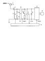
- FIG. 1 is a diagram illustrating a configuration example of an electric vehicle control device according to an embodiment.
- FIG. 2 is a diagram illustrating a configuration example of a control unit in the electric vehicle control device according to the embodiment.
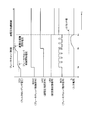
- FIG. 3 is a time chart for explaining the operation of the electric vehicle control apparatus according to the embodiment.
- FIG. 4 is a diagram showing a configuration of a general electric vehicle control device using an overvoltage suppression circuit.
- FIG. 1 is a diagram illustrating a configuration example of an electric vehicle control device according to an embodiment.
- the electric vehicle control device 50 receives DC power from the overhead wire 1 via the current collector 2 and the current breaker 3, and the inverter 11 exchanges the received DC power. It is the structure which drives the electric motor 12 which is converted into electric power and is a load.
- the electric vehicle control device 50 includes an inverter 11, a brake chopper circuit 8 in which a switching element 6 and a brake resistor 7 are connected in series, and a filter capacitor 10 that stores electric power supplied from the overhead wire 1.
- the One end of the brake chopper circuit 8 is connected to the DC bus 4a on the higher potential side, and the other end of the brake chopper circuit 8 is connected to the DC bus 4b on the lower potential side.
- the filter capacitor 10 is also connected between the DC buses 4a and 4b.
- a voltage detector 9 for detecting an applied voltage from the overhead line or a voltage of the filter capacitor 10 is provided between the DC buses 4a and 4b.
- a filter capacitor voltage FCV that is voltage information of the filter capacitor 10 detected by the voltage detector 9 is input to the control unit 13.
- the control unit 13 controls the inverter 11, the brake chopper circuit 8 and the circuit breaker 3 using the filter capacitor voltage FCV.
- FIG. 4 is a configuration example of an electric vehicle control device shown as a comparative example.
- the configuration is shown as a conventional configuration. 4, parts that are the same as or equivalent to those in FIG. 1 are given the same reference numerals.
- the overvoltage suppression circuit 5 is omitted in the electric vehicle control device 50 according to the embodiment.
- the function that the overvoltage suppression circuit 5 takes charge of is replaced by the brake chopper circuit 8 that operates under the control of the control unit 13.
- the brake chopper circuit 8 in the embodiment operates as a power consuming circuit having both the overvoltage suppressing function and the regenerative power consuming function of the original brake chopper circuit, and the brake resistor 7 provided in the brake chopper circuit 8 consumes power. Operates as a resistor. The details of the function that the brake chopper circuit 8 substitutes will be described later.
- the design philosophy is different between the overvoltage suppression circuit 5 and the brake chopper circuit 8, and the difference in the design philosophy appears as the difference between the overvoltage suppression resistor 5a and the brake resistor 7.
- the overvoltage suppression resistor 5a is intended to discharge the charge of the filter capacitor 10 when the voltage applied from the overhead wire 1 becomes an overvoltage.
- the overvoltage suppression circuit 5 is operated, the design considering cooperation with the substation, specifically, even if the overvoltage suppression thyristor 5b is ignited before the circuit breaker 3 is opened, the overvoltage suppression circuit 5 is in the substation.
- the ⁇ I detector is designed not to operate.
- the brake resistor 7 is designed so that the surplus power of the regenerative power from the motor 12 can be consumed quickly and without waste.
- R1> R2 there is generally a relationship of R1> R2 between the resistance value R1 of the overvoltage suppression resistor 5a and the resistance value R2 of the brake resistor 7. Therefore, when the brake chopper circuit 8 is used for overvoltage suppression control, since the current flowing from the substation increases, there is a possibility of operating the ⁇ I detection device, and in the electric vehicle control device having an overvoltage suppression function. It was the cause of the problem.
- the electric vehicle control device 50 realizes a control system configuration that does not operate the ⁇ I detection device even when the brake chopper circuit 8 is used as an overvoltage suppression circuit.
- FIG. It is a figure which shows one structural example of a type
- a first control system 13a related to brake chopper control is configured on the upper stage side
- a second control system 13b related to overvoltage suppression control is configured on the lower stage side.
- the first control system 13a includes a first comparator 13a1, a first conduction ratio calculation unit 13a2, and a first drive signal generation unit 13a3.
- the second control system 13b includes a second comparator. 13b1, a second flow rate calculating unit 13b2, and a second drive signal generating unit 13b3 are configured.
- An output unit 13 c is provided at the output stage of the control unit 13.
- the filter capacitor voltage FCV detected by the voltage detector 9 is input to the B terminal, and the first overvoltage determination value Va1 indicating the start voltage of the brake chopper control is input to the A terminal.
- the first comparator 13a1 compares the filter capacitor voltage FCV with the first overvoltage determination value Va1, and when the filter capacitor voltage FCV is equal to or higher than the first overvoltage determination value Va1, the brake chopper control command BCHC is set to the first value. Is output to the current flow rate calculation unit 13a2.
- the filter capacitor voltage FCV is input to the B terminal of the second comparator 13b1, and the A terminal of the second comparator 13b1 is a second voltage that indicates the start voltage of the overvoltage protection control.
- the overvoltage determination value Va2 is input.
- the second comparator 13b1 compares the filter capacitor voltage FCV and the second overvoltage determination value Va2, and if the filter capacitor voltage FCV is equal to or higher than the second overvoltage determination value Va2, the overvoltage protection command VPC is set to the second overvoltage protection command VPC. It outputs to the convection rate calculating part 13b2.
- a filter capacitor voltage FCV and a brake chopper control command BCHC generated by the first comparator 13a1 are input to the first duty ratio calculator 13a2. While the brake chopper control command BCHC is input, the first flow rate calculation unit 13a2 calculates a flow rate CUR1 that is the first flow rate according to the magnitude of the filter capacitor voltage FCV. 1 to the drive signal generator 13a3.
- the conduction rate means the ratio of the ON period to the period of one cycle of the ON pulse and the OFF pulse when controlling the switching element 7.
- An overvoltage protection command VPC generated by the second comparator 13b1 and a breaker state signal LBS from the breaker 3 are input to the second conduction ratio calculator 13b2.
- the breaker state signal LBS here is described as a signal that is output when the breaker 3 is closed.
- the second conduction ratio calculation unit 13b2 calculates the conduction ratio CUR2 that is the second conduction ratio while the overvoltage protection command VPC is input and the breaker state signal LBS is input.
- the circuit breaker release command LBR for opening the circuit breaker 3 and the inverter operation stop command INVS for stopping the operation of the inverter 11 are output to the second drive signal generation unit 13b3, respectively. 3 and the inverter 11. Note that there is a relationship of CUR2 ⁇ CUR1 between the flow rate CUR2 output from the second flow rate calculation unit 13b2 and the flow rate CUR1 output from the first flow rate calculation unit 13a2.
- the breaker 3 When the breaker release command LBR is input to the breaker 3, the breaker 3 is opened. When the breaker 3 is opened, the breaker state signal LBS is not output. When the breaker state signal LBS is interrupted from the state where both the overvoltage protection command VPC and the breaker state signal LBS are input, the second conduction rate calculation unit 13b2 passes the conduction rate CUR2. A third flow rate having a value larger than the flow rate CUR1 is set. The third flow rate may be larger than the flow rate CUR1, which is the first flow rate.
- the 3rd flow rate is produced
- the first drive signal generation unit 13a3 receives the conduction rate CUR1 calculated by the first conduction rate calculation unit 13a2.
- the first drive signal generation unit 13a3 generates a control pulse for driving the switching element 6 of the brake chopper circuit 8 according to the conduction ratio CUR1.
- the second drive signal generation unit 13b3 receives the conduction rate CUR2 calculated by the second conduction rate calculation unit 13b2.
- the second drive signal generator 13b3 generates a control pulse for driving the switching element 6 of the brake chopper circuit 8 according to the conduction ratio CUR2.
- the control pulse generated by the first drive signal generation unit 13a3 and the control pulse generated by the second drive signal generation unit 13b3 are input to the output unit 13c.
- the output unit 13c performs processing so that the control pulse generated by the second drive signal generation unit 13b3 is given priority, and the processed control pulse is processed by the brake chopper operation command BCX.
- BCX brake chopper operation command
- FIG. 3 is a time chart for explaining the operation when the electric vehicle control device detects an overvoltage.
- the filter capacitor voltage FCV the brake chopper control command BCHC
- the overvoltage protection command VPC the overvoltage protection command VPC
- the breaker state signal LBS the brake chopper operation command BCX
- the input current Ib flowing from the overhead line 1 from the upper stage side The waveform is shown.
- the voltage detector 9 detects an overvoltage state.
- the control unit 13 is configured as shown in FIG. 2, so that at time ta, the filter capacitor voltage FCV becomes the brake chopper control start voltage (first overvoltage determination in FIG. 2). It is determined that it has exceeded the value Va1).
- the operation of the control unit 13 described above outputs a brake chopper operation command BCX represented by a control pulse signal that is turned on / off at the conduction ratio CUR1, and the filter capacitor current from the filter capacitor 10 as shown in FIG. Ia flows into the brake chopper circuit 8.
- the switching element 6 is ON / OFF controlled, the input current Ib that attempts to flow from the overhead line 1 into the brake chopper circuit 8 is suppressed, and the ⁇ I detection device does not operate.
- the filter capacitor voltage FCV When the filter capacitor voltage FCV further rises, at time tb, it is determined that the filter capacitor voltage FCV has exceeded the overvoltage protection start voltage (corresponding to the second overvoltage determination value Va2 in FIG. 2), and the overvoltage protection command VPC is output. Is done.
- the overvoltage protection command VPC When the overvoltage protection command VPC is output, the circuit breaker release command LBR is output. However, as indicated by the circuit breaker state signal LBS, the circuit breaker 3 is immediately opened due to the delay time of the mechanical operation. Must not.
- the control unit 13 outputs a brake chopper operation command BCX represented by a control pulse signal that is turned on / off at a flow rate CUR2 with a reduced flow rate until the circuit breaker 3 is opened (from time tb to time tc).
- the switching element 6 is controlled. At this time, the input current Ib from the overhead line 1 flows, but since the conduction rate is lowered, the input current Ib can be suppressed so as not to exceed the ⁇ I set value which is a determination threshold.
- the conduction rate is changed to 100%, and the charge of the filter capacitor 10 is quickly discharged.
- the flow rate from when the breaker release command LBR is issued to when the breaker 3 is opened includes the ⁇ I set value, the resistance value of the brake resistor 7, the overvoltage set value, and the number of electric vehicle control devices. Can be determined by.
- the resistance value of the brake resistor 7 is Rb and the number of electric vehicle control devices per train is n, for example, the resistance value Rb of the brake resistor can be determined based on the following equation.
- the overvoltage suppression circuit and the brake chopper circuit can be shared, so that the device can be reduced in size and cost. .
- the second conduction rate when performing the overvoltage suppression control is smaller than the first conduction rate when performing the brake chopper control. Therefore, it is possible to suppress unintended unnecessary operation of the circuit breaker of the substation while realizing the sharing of the overvoltage suppression circuit and the brake chopper circuit.
- control is performed so that the current conduction rate is increased. While suppressing, it becomes possible to discharge the charge of the filter capacitor quickly.
- the configuration shown in the above embodiment is an example of the configuration of the present invention, and can be combined with another known technique, and a part thereof is omitted without departing from the gist of the present invention. Needless to say, the configuration can be changed.
- the present invention is useful as an electric vehicle control device having an overvoltage suppression function.
Landscapes
- Engineering & Computer Science (AREA)
- Power Engineering (AREA)
- Transportation (AREA)
- Mechanical Engineering (AREA)
- Life Sciences & Earth Sciences (AREA)
- Sustainable Development (AREA)
- Sustainable Energy (AREA)
- Electric Propulsion And Braking For Vehicles (AREA)
- Stopping Of Electric Motors (AREA)
Abstract
Description
図1は、実施の形態に係る電気車制御装置の一構成例を示す図である。実施の形態に係る電気車制御装置50は、図1に示すように、架線1からの直流電力を集電装置2および断流器3を介して受電し、受電した直流電力をインバータ11が交流電力に変換して負荷である電動機12を駆動する構成である。
第1のコンパレータ13a1では、電圧検出器9が検出したフィルタコンデンサ電圧FCVがB端子に入力され、A端子には、ブレーキチョッパ制御の開始電圧を意味する第1の過電圧判定値Va1が入力される。第1のコンパレータ13a1では、フィルタコンデンサ電圧FCVと第1の過電圧判定値Va1とが比較され、フィルタコンデンサ電圧FCVが第1の過電圧判定値Va1以上である場合に、ブレーキチョッパ制御指令BCHCを第1の通流率演算部13a2に出力する。
第2のコンパレータ13b1のB端子には、第1のコンパレータ13a1と同様に、フィルタコンデンサ電圧FCVが入力され、第2のコンパレータ13b1のA端子には、過電圧保護制御の開始電圧を意味する第2の過電圧判定値Va2が入力される。第2のコンパレータ13b1では、フィルタコンデンサ電圧FCVと第2の過電圧判定値Va2とが比較され、フィルタコンデンサ電圧FCVが第2の過電圧判定値Va2以上である場合に、過電圧保護指令VPCを第2の通流率演算部13b2に出力する。なお、第1の過電圧判定値Va1と第2の過電圧判定値Va2との間には、Va1<Va2の関係がある。よって、例えばフィルタコンデンサ電圧FCVが上昇する過程においては、過電圧保護指令VPCよりもブレーキチョッパ制御指令BCHCの方が先に生成される。
第1の通流率演算部13a2には、フィルタコンデンサ電圧FCVおよび第1のコンパレータ13a1が生成したブレーキチョッパ制御指令BCHCが入力される。第1の通流率演算部13a2は、ブレーキチョッパ制御指令BCHCが入力されている間、フィルタコンデンサ電圧FCVの大きさに応じた第1の通流率である通流率CUR1を演算して第1の駆動信号生成部13a3に出力する。なお、通流率とは、スイッチング素子7を制御する際のオンパルスおよびオフパルスの1周期の期間に占めるオン期間の比率を意味する。
第2の通流率演算部13b2には、第2のコンパレータ13b1が生成した過電圧保護指令VPCおよび断流器3からの断流器状態信号LBSが入力される。なお、ここでいう断流器状態信号LBSは、断流器3が閉路している場合に信号が出力されるものであるとして説明する。第2の通流率演算部13b2は、過電圧保護指令VPCが入力され、且つ、断流器状態信号LBSが入力されている間、第2の通流率である通流率CUR2を演算して第2の駆動信号生成部13b3に出力すると共に、断流器3を開放するための断流器開放指令LBRおよび、インバータ11の動作を停止するためのインバータ動作停止指令INVSを、それぞれ断流器3およびインバータ11に出力する。なお、第2の通流率演算部13b2が出力する通流率CUR2と第1の通流率演算部13a2が出力する通流率CUR1との間には、CUR2<CUR1の関係がある。
第1の駆動信号生成部13a3には、第1の通流率演算部13a2が演算した通流率CUR1が入力される。第1の駆動信号生成部13a3は、通流率CUR1に従って、ブレーキチョッパ回路8のスイッチング素子6を駆動するための制御パルスを生成する。
第2の駆動信号生成部13b3には、第2の通流率演算部13b2が演算した通流率CUR2が入力される。第2の駆動信号生成部13b3は、通流率CUR2に従って、ブレーキチョッパ回路8のスイッチング素子6を駆動するための制御パルスを生成する。
第1の駆動信号生成部13a3が生成した制御パルスおよび、第2の駆動信号生成部13b3が生成した制御パルスは、出力部13cに入力される。出力部13cが、双方の制御パルスが生成されている場合には、第2の駆動信号生成部13b3が生成した制御パルスが優先されるように処理し、処理した制御パルスをブレーキチョッパ動作指令BCXとしてブレーキチョッパ回路8に出力し、ブレーキチョッパ回路8のスイッチング素子6を制御する。
Claims (4)
- 断流器および直流母線を介して供給される電力を受電して電動機を駆動するインバータと、
スイッチング素子および前記スイッチング素子に直列接続される電力消費抵抗を具備し、前記インバータに並列接続される電力消費回路と、
前記直流母線に印加される母線電圧を検出する電圧検出器と、
前記電動機からの回生電力を前記電力消費抵抗で消費させる電力消費制御と、前記母線電圧の過電圧を抑制する過電圧抑制制御とを行う制御部と、
を備え、
前記制御部は、前記電力消費制御を行う際の第1の通流率よりも、前記過電圧抑制制御行う際の第2の通流率の方が小さくなるように前記スイッチング素子を制御する
ことを特徴とする電気車制御装置。 - 前記制御部には、前記電力消費制御を行う第1の制御系と、前記過電圧抑制制御を行う第2の制御系と、が構成され、
前記制御部は、前記母線電圧が第1の判定値以上のときに前記第1の制御系の動作を開始させ、
前記母線電圧が第1の判定値よりも大きな第2の判定値以上のときに前記第2の制御系の動作を開始させ、
前記第1の制御系と前記第2の制御系とを同時に動作させるときには、前記第2の制御系の動作を優先する
ことを特徴とする請求項1に記載の電気車制御装置。 - 前記第2の制御系には、前記断流器の開閉情報が入力され、
前記第2の制御系は、前記断流器の開情報を確認したときには前記第1の通流率よりも大きな第3の通流率を算出し、当該第3の通流率に従って前記スイッチング素子を制御する
ことを特徴とする請求項2に記載の電気車制御装置。 - 前記第3の通流率は、100%であることを特徴とする請求項3に記載の電気車制御装置。
Priority Applications (4)
| Application Number | Priority Date | Filing Date | Title |
|---|---|---|---|
| US15/502,888 US9975433B2 (en) | 2014-08-25 | 2014-08-25 | Electric vehicle controller |
| JP2016545099A JP6177445B2 (ja) | 2014-08-25 | 2014-08-25 | 電気車制御装置 |
| PCT/JP2014/072145 WO2016030941A1 (ja) | 2014-08-25 | 2014-08-25 | 電気車制御装置 |
| EP14900608.2A EP3188357B1 (en) | 2014-08-25 | 2014-08-25 | Control device for electric rolling stock |
Applications Claiming Priority (1)
| Application Number | Priority Date | Filing Date | Title |
|---|---|---|---|
| PCT/JP2014/072145 WO2016030941A1 (ja) | 2014-08-25 | 2014-08-25 | 電気車制御装置 |
Publications (1)
| Publication Number | Publication Date |
|---|---|
| WO2016030941A1 true WO2016030941A1 (ja) | 2016-03-03 |
Family
ID=55398886
Family Applications (1)
| Application Number | Title | Priority Date | Filing Date |
|---|---|---|---|
| PCT/JP2014/072145 WO2016030941A1 (ja) | 2014-08-25 | 2014-08-25 | 電気車制御装置 |
Country Status (4)
| Country | Link |
|---|---|
| US (1) | US9975433B2 (ja) |
| EP (1) | EP3188357B1 (ja) |
| JP (1) | JP6177445B2 (ja) |
| WO (1) | WO2016030941A1 (ja) |
Families Citing this family (8)
| Publication number | Priority date | Publication date | Assignee | Title |
|---|---|---|---|---|
| CN107776412B (zh) * | 2017-09-29 | 2021-01-19 | 苏州汇川联合动力系统有限公司 | 一种制动电阻放电控制系统以及方法 |
| CN110315987B (zh) * | 2018-03-29 | 2021-06-18 | 比亚迪股份有限公司 | 制动回馈控制方法 |
| CN110315986B (zh) * | 2018-03-29 | 2021-06-18 | 比亚迪股份有限公司 | 制动回馈控制系统及车辆 |
| CN111463766A (zh) * | 2019-01-21 | 2020-07-28 | 广东美的制冷设备有限公司 | 供电保护电路板和空调器 |
| CN112172763B (zh) * | 2019-07-05 | 2021-09-10 | 株洲中车时代电气股份有限公司 | 一种混合动力有轨电车电制动功率分配方法、装置和介质 |
| US20240140205A1 (en) * | 2019-11-26 | 2024-05-02 | Mitsubishi Electric Corporation | Propulsion control device and propulsion control method |
| CN111413910A (zh) * | 2020-04-15 | 2020-07-14 | 中国铁道科学研究院集团有限公司 | 断路器分合闸控制方法、装置及系统 |
| US11463037B2 (en) * | 2020-09-10 | 2022-10-04 | Delta Electronics, Inc. | Motor control system and method of controlling the same |
Citations (3)
| Publication number | Priority date | Publication date | Assignee | Title |
|---|---|---|---|---|
| JPS6233689U (ja) * | 1985-08-08 | 1987-02-27 | ||
| JPS62247701A (ja) * | 1986-04-18 | 1987-10-28 | Mitsubishi Electric Corp | 電気車の制動制御装置 |
| JPH04197003A (ja) * | 1990-11-28 | 1992-07-16 | Hitachi Ltd | 電気車制御装置 |
Family Cites Families (12)
| Publication number | Priority date | Publication date | Assignee | Title |
|---|---|---|---|---|
| JP2811817B2 (ja) | 1989-10-18 | 1998-10-15 | 三菱電機株式会社 | 電気車制御装置 |
| JPH03159501A (ja) | 1989-11-15 | 1991-07-09 | Toshiba Corp | 電気車制御装置 |
| JP3232417B2 (ja) * | 1992-06-26 | 2001-11-26 | 株式会社日立製作所 | 電気車用インバータ制御装置 |
| US5291106A (en) * | 1992-11-23 | 1994-03-01 | General Motors Corporation | Single current regulator for controlled motoring and braking of a DC-fed electric motor |
| US5420491A (en) * | 1992-12-02 | 1995-05-30 | Otis Elevator Company | Method for consuming regenerated power for elevators |
| JPH11166744A (ja) | 1997-12-03 | 1999-06-22 | Tokyo Giei Kk | 浴湯供給装置 |
| JP2000358384A (ja) | 1999-06-14 | 2000-12-26 | Mitsubishi Electric Corp | 電力制御装置 |
| KR100488528B1 (ko) * | 2003-05-16 | 2005-05-11 | 삼성전자주식회사 | 모터전원공급장치 |
| JP3772898B2 (ja) * | 2004-09-08 | 2006-05-10 | ダイキン工業株式会社 | 多相電流供給回路及び駆動装置 |
| US20090284199A1 (en) * | 2006-06-27 | 2009-11-19 | Hidetoshi Kitanaka | Electric Power Converter |
| JP4772718B2 (ja) | 2007-03-13 | 2011-09-14 | 株式会社日立製作所 | 鉄道車両の駆動システム |
| JP2009189198A (ja) * | 2008-02-08 | 2009-08-20 | Toyo Electric Mfg Co Ltd | 電気車制御装置 |
-
2014
- 2014-08-25 US US15/502,888 patent/US9975433B2/en active Active
- 2014-08-25 JP JP2016545099A patent/JP6177445B2/ja active Active
- 2014-08-25 EP EP14900608.2A patent/EP3188357B1/en active Active
- 2014-08-25 WO PCT/JP2014/072145 patent/WO2016030941A1/ja active Application Filing
Patent Citations (3)
| Publication number | Priority date | Publication date | Assignee | Title |
|---|---|---|---|---|
| JPS6233689U (ja) * | 1985-08-08 | 1987-02-27 | ||
| JPS62247701A (ja) * | 1986-04-18 | 1987-10-28 | Mitsubishi Electric Corp | 電気車の制動制御装置 |
| JPH04197003A (ja) * | 1990-11-28 | 1992-07-16 | Hitachi Ltd | 電気車制御装置 |
Also Published As
| Publication number | Publication date |
|---|---|
| EP3188357A4 (en) | 2018-04-11 |
| EP3188357A1 (en) | 2017-07-05 |
| US20170232847A1 (en) | 2017-08-17 |
| US9975433B2 (en) | 2018-05-22 |
| EP3188357B1 (en) | 2019-04-03 |
| JPWO2016030941A1 (ja) | 2017-04-27 |
| JP6177445B2 (ja) | 2017-08-09 |
Similar Documents
| Publication | Publication Date | Title |
|---|---|---|
| JP6177445B2 (ja) | 電気車制御装置 | |
| CN108684214B (zh) | 电力变换装置 | |
| JP5819022B2 (ja) | 鉄道車両の推進制御装置 | |
| CN103582993B (zh) | 逆变器驱动装置 | |
| JP5794301B2 (ja) | 車両および車両の制御方法 | |
| JP6361466B2 (ja) | 放電制御装置、及び、これを備える電力変換装置 | |
| EP2432117A1 (en) | Power conversion device, and method for controlling the condenser voltage of the power conversion device | |
| JP5692018B2 (ja) | 電気自動車 | |
| JP2008263741A5 (ja) | ||
| US10256746B2 (en) | Low-voltage discharge and actuation circuit for the traction converter of a vehicle | |
| JP2008168795A (ja) | 給電設備 | |
| JP2015033233A (ja) | 電源回路の異常検出方法 | |
| TW201515379A (zh) | 交流馬達驅動系統 | |
| JPWO2017130668A1 (ja) | 電力変換装置 | |
| JP2008228451A (ja) | 鉄道車両の駆動システム | |
| JP5696589B2 (ja) | 車両および車両の制御方法 | |
| JP2005206111A (ja) | 直流電圧給電装置 | |
| JP2009189198A (ja) | 電気車制御装置 | |
| JP6087753B2 (ja) | 電力システム | |
| EP4116129A1 (en) | A method and a master control unit for controlling an electrical system of an electric vehicle | |
| JP2006067732A (ja) | 電気車制御装置 | |
| JP2019004594A (ja) | 車両の電源装置 | |
| JP2013121300A (ja) | フィルタコンデンサの放電方法 | |
| US9751408B2 (en) | Motor driving unit | |
| JP2007209200A (ja) | 電気車制御装置 |
Legal Events
| Date | Code | Title | Description |
|---|---|---|---|
| 121 | Ep: the epo has been informed by wipo that ep was designated in this application |
Ref document number: 14900608 Country of ref document: EP Kind code of ref document: A1 |
|
| ENP | Entry into the national phase |
Ref document number: 2016545099 Country of ref document: JP Kind code of ref document: A |
|
| REEP | Request for entry into the european phase |
Ref document number: 2014900608 Country of ref document: EP |
|
| WWE | Wipo information: entry into national phase |
Ref document number: 2014900608 Country of ref document: EP |
|
| WWE | Wipo information: entry into national phase |
Ref document number: 15502888 Country of ref document: US |
|
| NENP | Non-entry into the national phase |
Ref country code: DE |