WO2016027351A1 - 運転支援装置及び運転支援方法 - Google Patents
運転支援装置及び運転支援方法 Download PDFInfo
- Publication number
- WO2016027351A1 WO2016027351A1 PCT/JP2014/071902 JP2014071902W WO2016027351A1 WO 2016027351 A1 WO2016027351 A1 WO 2016027351A1 JP 2014071902 W JP2014071902 W JP 2014071902W WO 2016027351 A1 WO2016027351 A1 WO 2016027351A1
- Authority
- WO
- WIPO (PCT)
- Prior art keywords
- vehicle
- standby position
- unit
- left turn
- driving support
- Prior art date
Links
Images


Classifications
-
- G—PHYSICS
- G08—SIGNALLING
- G08G—TRAFFIC CONTROL SYSTEMS
- G08G1/00—Traffic control systems for road vehicles
- G08G1/16—Anti-collision systems
- G08G1/167—Driving aids for lane monitoring, lane changing, e.g. blind spot detection
-
- G—PHYSICS
- G08—SIGNALLING
- G08G—TRAFFIC CONTROL SYSTEMS
- G08G1/00—Traffic control systems for road vehicles
- G08G1/09—Arrangements for giving variable traffic instructions
- G08G1/0962—Arrangements for giving variable traffic instructions having an indicator mounted inside the vehicle, e.g. giving voice messages
- G08G1/0968—Systems involving transmission of navigation instructions to the vehicle
-
- B—PERFORMING OPERATIONS; TRANSPORTING
- B60—VEHICLES IN GENERAL
- B60R—VEHICLES, VEHICLE FITTINGS, OR VEHICLE PARTS, NOT OTHERWISE PROVIDED FOR
- B60R21/00—Arrangements or fittings on vehicles for protecting or preventing injuries to occupants or pedestrians in case of accidents or other traffic risks
-
- B—PERFORMING OPERATIONS; TRANSPORTING
- B60—VEHICLES IN GENERAL
- B60W—CONJOINT CONTROL OF VEHICLE SUB-UNITS OF DIFFERENT TYPE OR DIFFERENT FUNCTION; CONTROL SYSTEMS SPECIALLY ADAPTED FOR HYBRID VEHICLES; ROAD VEHICLE DRIVE CONTROL SYSTEMS FOR PURPOSES NOT RELATED TO THE CONTROL OF A PARTICULAR SUB-UNIT
- B60W30/00—Purposes of road vehicle drive control systems not related to the control of a particular sub-unit, e.g. of systems using conjoint control of vehicle sub-units, or advanced driver assistance systems for ensuring comfort, stability and safety or drive control systems for propelling or retarding the vehicle
- B60W30/18—Propelling the vehicle
- B60W30/18009—Propelling the vehicle related to particular drive situations
- B60W30/18154—Approaching an intersection
-
- B—PERFORMING OPERATIONS; TRANSPORTING
- B60—VEHICLES IN GENERAL
- B60W—CONJOINT CONTROL OF VEHICLE SUB-UNITS OF DIFFERENT TYPE OR DIFFERENT FUNCTION; CONTROL SYSTEMS SPECIALLY ADAPTED FOR HYBRID VEHICLES; ROAD VEHICLE DRIVE CONTROL SYSTEMS FOR PURPOSES NOT RELATED TO THE CONTROL OF A PARTICULAR SUB-UNIT
- B60W40/00—Estimation or calculation of non-directly measurable driving parameters for road vehicle drive control systems not related to the control of a particular sub unit, e.g. by using mathematical models
- B60W40/02—Estimation or calculation of non-directly measurable driving parameters for road vehicle drive control systems not related to the control of a particular sub unit, e.g. by using mathematical models related to ambient conditions
- B60W40/04—Traffic conditions
-
- B—PERFORMING OPERATIONS; TRANSPORTING
- B60—VEHICLES IN GENERAL
- B60W—CONJOINT CONTROL OF VEHICLE SUB-UNITS OF DIFFERENT TYPE OR DIFFERENT FUNCTION; CONTROL SYSTEMS SPECIALLY ADAPTED FOR HYBRID VEHICLES; ROAD VEHICLE DRIVE CONTROL SYSTEMS FOR PURPOSES NOT RELATED TO THE CONTROL OF A PARTICULAR SUB-UNIT
- B60W40/00—Estimation or calculation of non-directly measurable driving parameters for road vehicle drive control systems not related to the control of a particular sub unit, e.g. by using mathematical models
- B60W40/08—Estimation or calculation of non-directly measurable driving parameters for road vehicle drive control systems not related to the control of a particular sub unit, e.g. by using mathematical models related to drivers or passengers
- B60W40/09—Driving style or behaviour
-
- G—PHYSICS
- G08—SIGNALLING
- G08G—TRAFFIC CONTROL SYSTEMS
- G08G1/00—Traffic control systems for road vehicles
- G08G1/09—Arrangements for giving variable traffic instructions
- G08G1/095—Traffic lights
-
- G—PHYSICS
- G08—SIGNALLING
- G08G—TRAFFIC CONTROL SYSTEMS
- G08G1/00—Traffic control systems for road vehicles
- G08G1/09—Arrangements for giving variable traffic instructions
- G08G1/0962—Arrangements for giving variable traffic instructions having an indicator mounted inside the vehicle, e.g. giving voice messages
- G08G1/09623—Systems involving the acquisition of information from passive traffic signs by means mounted on the vehicle
-
- G—PHYSICS
- G08—SIGNALLING
- G08G—TRAFFIC CONTROL SYSTEMS
- G08G1/00—Traffic control systems for road vehicles
- G08G1/16—Anti-collision systems
-
- G—PHYSICS
- G08—SIGNALLING
- G08G—TRAFFIC CONTROL SYSTEMS
- G08G1/00—Traffic control systems for road vehicles
- G08G1/16—Anti-collision systems
- G08G1/166—Anti-collision systems for active traffic, e.g. moving vehicles, pedestrians, bikes
-
- B—PERFORMING OPERATIONS; TRANSPORTING
- B60—VEHICLES IN GENERAL
- B60W—CONJOINT CONTROL OF VEHICLE SUB-UNITS OF DIFFERENT TYPE OR DIFFERENT FUNCTION; CONTROL SYSTEMS SPECIALLY ADAPTED FOR HYBRID VEHICLES; ROAD VEHICLE DRIVE CONTROL SYSTEMS FOR PURPOSES NOT RELATED TO THE CONTROL OF A PARTICULAR SUB-UNIT
- B60W2554/00—Input parameters relating to objects
- B60W2554/80—Spatial relation or speed relative to objects
- B60W2554/801—Lateral distance
-
- B—PERFORMING OPERATIONS; TRANSPORTING
- B60—VEHICLES IN GENERAL
- B60W—CONJOINT CONTROL OF VEHICLE SUB-UNITS OF DIFFERENT TYPE OR DIFFERENT FUNCTION; CONTROL SYSTEMS SPECIALLY ADAPTED FOR HYBRID VEHICLES; ROAD VEHICLE DRIVE CONTROL SYSTEMS FOR PURPOSES NOT RELATED TO THE CONTROL OF A PARTICULAR SUB-UNIT
- B60W2554/00—Input parameters relating to objects
- B60W2554/80—Spatial relation or speed relative to objects
- B60W2554/802—Longitudinal distance
-
- B—PERFORMING OPERATIONS; TRANSPORTING
- B60—VEHICLES IN GENERAL
- B60W—CONJOINT CONTROL OF VEHICLE SUB-UNITS OF DIFFERENT TYPE OR DIFFERENT FUNCTION; CONTROL SYSTEMS SPECIALLY ADAPTED FOR HYBRID VEHICLES; ROAD VEHICLE DRIVE CONTROL SYSTEMS FOR PURPOSES NOT RELATED TO THE CONTROL OF A PARTICULAR SUB-UNIT
- B60W2555/00—Input parameters relating to exterior conditions, not covered by groups B60W2552/00, B60W2554/00
- B60W2555/60—Traffic rules, e.g. speed limits or right of way
Definitions
- the present invention relates to a driving support device and a driving support method for supporting driving of a vehicle.
- Patent Document 1 does not propose a stop position that takes into account a blind spot caused by a vehicle waiting for a right or left turn from an oncoming lane, because the support method for the right or left turn is not limited to risk notification to the driver.
- an object of the present invention is to provide a driving support device and a driving support method that can make a host vehicle wait for a right or left turn at a position that takes into account the risk and efficiency when making a right or left turn. .
- the object detection unit detects an object ahead of the host vehicle, and the host vehicle is detected after a predetermined time based on the current position of the host vehicle and the travel route of the host vehicle in the road information.
- left / right turn information indicating that a right / left turn is made across the opposite lane at the intersection is detected, and right / left turn information is detected
- the right / left turn from the opposite lane is detected based on the detection result of the object detection unit and the road information. It is determined whether there is a waiting vehicle waiting in the intersection, and the blind spot in the oncoming lane of the object detection unit formed by the waiting vehicle is estimated. Based on the estimated blind spot, the vehicle turns right or left. Set the standby area to wait.
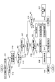
- FIG. 1 is a block diagram illustrating a basic configuration of the driving support apparatus according to the first embodiment of the present invention.
- FIG. 2 is a schematic block diagram illustrating a basic configuration of a vehicle on which the driving support apparatus according to the first embodiment of the present invention is mounted.
- FIG. 3 is a flowchart for explaining the operation of the driving support apparatus according to the first embodiment of the present invention.
- FIG. 4 is a diagram for explaining the operation of the driving support apparatus according to the first embodiment of the present invention.
- FIG. 5 is a diagram for explaining the operation of the driving support apparatus according to the first embodiment of the present invention.
- FIG. 6 is a diagram for explaining the operation of the driving support apparatus according to the first embodiment of the present invention.
- FIG. 1 is a block diagram illustrating a basic configuration of the driving support apparatus according to the first embodiment of the present invention.
- FIG. 2 is a schematic block diagram illustrating a basic configuration of a vehicle on which the driving support apparatus according to the first embodiment of the present invention is mounted.
- FIG. 7 is a diagram for explaining the operation of the driving support apparatus according to the first embodiment of the present invention.
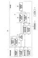
- FIG. 8 is a block diagram illustrating a basic configuration of the driving support apparatus according to the second embodiment of the present invention.
- FIG. 9 is a flowchart for explaining the operation of the driving support apparatus according to the second embodiment of the present invention.
- FIG. 10 is a flowchart for explaining in detail the processing in step S21 of the flowchart of FIG.
- FIG. 11 is a diagram for explaining the operation of the driving support apparatus according to the second embodiment of the present invention.
- FIG. 12 is a diagram for explaining an Ackermann turning model.
- the driving support device As shown in FIG. 1, the driving support device according to the first embodiment of the present invention is supplied with various information by the information supply unit 1 and the information supply unit 1, and processes calculations necessary for the operation of the driving support device.
- a processing unit 2 a vehicle control unit 3, and an output unit 5.
- the driving support device As shown in FIG. 2, the driving support device according to the first embodiment is mounted on a vehicle and supports driving when the host vehicle C turns right or left.
- the own vehicle C may be an automatically driven vehicle that automatically drives a set travel route, or may be a vehicle that travels in response to an operation of the driver.
- the information supply unit 1 includes a road information acquisition unit 11, a vehicle position acquisition unit 12, an object detection unit 13, and a right / left turn information detection unit 14.
- the road information acquisition unit 11 acquires road information on which the vehicle C can travel and outputs the road information to the processing unit 2.
- the road information acquisition part 11 is comprised from the car navigation apparatus etc. which hold
- the road information includes road width, radius of curvature, intersection size, number of lanes, type, legal speed, and the like.
- the own vehicle position acquisition unit 12 acquires the current position of the own vehicle C in the road information acquired by the road information acquisition unit 11.
- the own vehicle position acquisition unit 12 includes a positioning device 121 such as a global positioning system (GPS) receiver, a gyro sensor 122, a rudder angle sensor 123, and a vehicle speed sensor 124.
- the own vehicle position acquisition unit 12 complements the position acquired by the positioning device 121 with the detection results of the gyro sensor 122, the rudder angle sensor 123, the vehicle speed sensor 124, and an external recognition sensor such as a camera, and the current position of the own vehicle C. Get as.
- GPS global positioning system
- the object detection unit 13 detects an object in front of the host vehicle C.
- the object detection unit 13 is configured by an external recognition sensor such as a laser range finder having an angular resolution and a distance resolution, for example.
- a plurality of object detection units 13 may be provided so as to detect not only the front of the host vehicle C but also the objects around the host vehicle C, and may include an external recognition sensor such as a camera.
- the right / left turn information detection unit 14 makes a right / left turn across the opposite lane at the intersection after a predetermined time based on the current position and travel route of the own vehicle C in the road information acquired by the road information acquisition unit 11. Detects left / right turn information indicating that it is to be performed.
- the right / left turn information detection unit 14 may be configured by the same car navigation device as the road information acquisition unit 11, for example. In the car navigation device, the travel route is set in advance on a digital map which is road information by the user. Further, the right / left turn information detection unit 14 may detect right / left turn information by a driver's turn signal operation.
- the processing unit 2 includes a standby vehicle determination unit 21, a blind spot estimation unit 22, a standby area setting unit 23, a right / left turn required time calculation unit 24, a vehicle head time calculation unit 25, and a standby position setting unit 26.
- Each unit constituting the processing unit 2 is a display as a logical structure, and may be configured as integral hardware or may be configured as separate hardware.
- the standby vehicle determination unit 21 determines whether there is a standby vehicle that waits at the intersection indicated by the right / left turn information from the oncoming lane. to decide.
- the standby vehicle determination unit 21 determines whether there is a standby vehicle based on the detection result of the object detection unit 13 and the road information acquired by the road information acquisition unit 11.
- the standby vehicle determination unit 21 recognizes the standby vehicle by assigning the detection result of the object detection unit 13 to the digital map of the road information acquisition unit 11 using the current position of the host vehicle C.
- the blind spot estimation unit 22 estimates the blind spot in the oncoming lane of the object detection unit 13 that can be formed by the standby vehicle or the like detected by the standby vehicle determination unit 21. Based on the blind spot estimated by the blind spot estimator 22, the standby area setting unit 23 determines the opposite lane necessary for the vehicle C to make a safe left or right turn while the host vehicle C waits for a right or left turn. A standby area that can be detected is set.
- the right / left turn required time calculation unit 24 Based on the road information acquired by the road information acquisition unit 11, the right / left turn required time calculation unit 24 completes after starting a right / left turn at each position in the stand-by area where the vehicle C can wait for a right / left turn. Each required time Tb until calculation is calculated.
- the standby possible area is an area from the position where the vehicle C can stop before the stop line of the intersection to the vicinity of the center of the intersection, for example.
- the right / left turn required time calculation unit 24 calculates the required time Tb based on the size of the intersection indicated by the right / left turn information detected by the right / left turn information detection unit 14 and the turning curvature of the host vehicle C.
- the required time Tb is the time from when the vehicle C starts turning right and left until it reaches a position that does not hinder the movement of an object (another vehicle) moving within the intersection.
- the vehicle head time calculation unit 25 determines the vehicle head time (THW: time headway) for a vehicle traveling in the opposite lane until the host vehicle C enters the intersection indicated by the right / left turn information detected by the right / left turn information detection unit 14. Ta is calculated.
- the head time Ta corresponds to the traffic volume of the oncoming lane.
- the vehicle head time calculation unit 25 calculates the time from when a vehicle traveling straight on the oncoming lane passes a predetermined point in the intersection until the next succeeding vehicle passes the same point, or one oncoming straight vehicle is within the intersection. The average value, minimum value, etc. of the time passing through the predetermined distance are calculated as the vehicle head time Ta.
- the vehicle head time calculation unit 25 recognizes the position of the oncoming vehicle by assigning the detection result of the object detection unit 13 to the digital map of the road information acquisition unit 11 using the current position of the host vehicle C.
- the standby position setting unit 26 is a standby set by the standby region setting unit 23 based on the required time Tb calculated by the right / left turn required time calculation unit 24 and the vehicle head time Ta calculated by the vehicle head time calculation unit 25. In the area, a standby position where the own vehicle C waits for a right or left turn is set. For example, the standby position setting unit 26 sets the standby position so that the required time Tb and the vehicle head time Ta are close to each other.
- the vehicle control unit 3 includes a drive unit 31 that drives the host vehicle C in the front-rear direction, a brake 32 that brakes the host vehicle C, and an EPS (Electric Power that changes the traveling direction of the host vehicle C. Steering) motor 33 and the like.
- the drive unit 31 includes, for example, a motor that rotates the wheels 42 and an inverter that drives the motor.
- the EPS motor 33 changes the direction of the front wheel 42 by being driven according to the rotation of the steering wheel 41.
- the configuration of the vehicle control unit 3 is an example, and for example, the drive unit 31 may be another configuration such as an internal combustion engine, and the EPS motor 33 may be a hydraulic steering system.
- the output unit 5 notifies the user of various information according to the control of the processing unit 2.
- the output unit 5 includes, for example, a display device that displays light, images, characters, and the like, and an output device such as a speaker that outputs sound.
- the host vehicle C equipped with the driving support device according to the first embodiment generates a travel route to the destination set in the car navigation device by the user, and at the intersection on the travel route, displays the opposite lane.
- the case of making a right turn across will be described.
- the following explanation is for the case where the vehicle C complies with traffic regulations that regulate left-hand traffic, but even if it is traffic regulations that regulate right-hand traffic, it can be similarly applied to the case of making a left turn across the oncoming lane. .
- step S101 the processing unit 2 acquires the current position of the vehicle C in the road information and the detection result by the object detection unit 13 from the vehicle position acquisition unit 12 at a predetermined sampling cycle.
- step S102 the right / left turn information detection unit 14 determines whether to detect right / left turn information indicating that the own vehicle C makes a right turn across the opposite lane at the intersection after a predetermined time. If right / left turn information is not detected, the process proceeds to step S103. If right / left turn information is detected, the process proceeds to step S104. In step S103, the host vehicle C continues normal driving and returns to step S101.
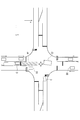
- step S ⁇ b> 104 the vehicle head time calculation unit 25 calculates the vehicle head time Ta for the oncoming straight vehicle based on the road information, the current position of the host vehicle C, and the detection result of the object detection unit 13. For example, in FIG. 4, the vehicle D ⁇ b> 2 and the vehicle D ⁇ b> 3 correspond to oncoming straight vehicles with respect to the host vehicle C.
- the vehicle head time calculation unit 25 calculates, as the vehicle head time Ta, the time from when the vehicle D2 passes a predetermined point in the intersection until the vehicle D3 passes the same point.
- step S105 the processing unit 2 determines whether or not the vehicle C can enter the intersection.
- the processing unit 2 can, for example, display a signal from an object detection unit 13 such as a camera that functions as a traffic signal at an intersection and a signal detection unit that detects a signal displayed on the traffic signal.
- an object detection unit 13 such as a camera that functions as a traffic signal at an intersection
- a signal detection unit that detects a signal displayed on the traffic signal.
- step S106 the processing unit 2 guides the host vehicle C so that the host vehicle C stops just before the stop line that becomes the boundary of the intersection as shown in FIG. 4, and returns the process to step S101.
- the processing unit 2 controls the vehicle control unit 3 to drive the host vehicle C so as to stop immediately before the stop line.
- the processing unit 2 provides a voice or image to the driver via the output unit 5 so that the host vehicle C stops immediately before the stop line. To guide. Further, the processing unit 2 may stop the traveling vehicle C by the brake 32 immediately before the stop line.
- step S107 the left / right turn required time calculation unit 24 sets each position x at a predetermined interval in the traveling direction (x direction) of the host vehicle C in the standby possible region R1 as a temporary standby position, as shown in FIG.
- the right turn completion position that does not hinder the movement of other vehicles moving within the intersection is, for example, the position of the host vehicle C indicated by a broken line in FIG.
- the position at which the vehicle enters the leftmost lane may be the right turn completion position, and may be changed as appropriate according to traffic conditions and the like.
- step S108 the processing unit 2 determines whether or not the host vehicle C is waiting for a right turn at the standby position set by the standby position setting unit 26. If it is waiting, the process proceeds to step S109. If it is not waiting, the process proceeds to step S115.
- step S109 the standby vehicle determination unit 21 determines whether there is a standby vehicle that waits in the intersection for a right turn from the oncoming lane. For example, in FIG. 4, a vehicle D1 that stops within an intersection corresponds to a standby vehicle. If there is a standby vehicle, the process proceeds to step S110. If there is a standby vehicle, the process proceeds to step S112.
- step S110 the standby position setting unit 26, as shown in FIG. 5, on the basis of the headway time Ta calculated respectively with each required time Tb x in step S104 and step S107, the vehicle C will wait for a right turn A standby position P1 is set.
- step S111 the standby position setting unit 26 guides the host vehicle C to the standby position P1, and returns the process to step S101.
- the standby position setting unit 26 controls the vehicle control unit 3 to drive the host vehicle C so as to stop at the standby position P1.
- the standby position setting unit 26 guides the driver via the output unit 5 so that the host vehicle C stops at the standby position P1 when the host vehicle C is a vehicle that travels according to the driver's operation. .
- the standby position setting unit 26 may stop the traveling vehicle C at the standby position P1 by the brake 32.
- the blind spot estimation unit 22 estimates a blind spot in the oncoming lane of the object detection unit 13 formed by the standby vehicle detected by the standby vehicle determination unit 21 for each position in the standby possible region R1. For example, as shown in FIG. 6, the blind spot estimation unit 22 estimates the blind spot of the object detection unit 13 formed by the vehicle D ⁇ b> 1 that is a standby vehicle. The blind spot estimation unit 22 detects the position of the standby vehicle based on the road information, the current position of the host vehicle C, and the detection result of the object detection unit 13, and assigns the position of the host vehicle C and the standby vehicle to the digital map. In the example shown in FIG.
- the blind spot is formed in the opposite lane on the right side of the straight line L1 connecting the object detection unit 13 and the end of the vehicle D1.
- the blind spot estimation unit 22 may estimate the blind spot based on the detection field of view, the angular resolution, and the distance resolution of the object detection unit 13.
- the blind spot estimation unit 22 estimates the blind spot for each position in the x direction and the y direction (left and right direction of the host vehicle C) orthogonal to the x direction in the standby possible region R1. For example, when the guidance method of the host vehicle C is the brake 32 or the output unit 5, the blind spot estimation unit 22 is limited to the y direction position of the host vehicle C on the stop line, and estimates the blind spot for each position in the x direction. It may be. In addition, when the guidance method of the host vehicle C is automatic driving, the blind spot estimation unit 22 limits each position in the x direction to a position in the y direction that is close to the opposite lane side in the traveling lane in order to improve the visibility as much as possible. The blind spot may be estimated.
- the blind spot estimation unit 22 is in the y direction near the opposite lane side in order to guide the output unit 5 to a position close to the opposite lane side in the traveling lane.
- the blind spot may be estimated limited to the position.
- Each position in the x direction used by the blind spot estimation unit 22 for estimation of the blind spot is each position used for calculating the required time Tb in step S107.
- the dead angle is smaller as the position of the own vehicle C waiting for a right turn is closer, but the required time Tb x required for the right turn is longer.
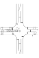
- step S113 the standby area setting unit 23, as shown in FIG. 7, is based on the blind spot estimated by the blind spot estimation unit 22, while the host vehicle C waits for a right turn, from the host vehicle C to the oncoming lane to be seen.
- a standby area R2 in which the distance can be predicted is set in the standby possible area R1.
- the standby area R2 is an area where, for example, the distance to the oncoming lane to be detected by the object detection unit 13 can be detected.
- the standby area setting unit 23 determines the distance that the oncoming lane should be looked at based on the legal speed of the oncoming lane included in the road information.
- step S114 the standby position setting unit 26, based on the headway time Ta calculated respectively with each required time Tb x in step S104 and step S107, sets the stand-by position P1 to the vehicle C will wait for a right turn.
- Standby position setting unit 26 the time required Tb x is a temporary waiting position of the headway time Ta becomes close waiting area R2, is set as the standby position P1, the process proceeds to step S111.
- step S115 the processing unit 2 can turn right from the standby position set by the standby position setting unit 26 based on the road information, the current position of the own vehicle C, and the detection result of the object detection unit 13. Determine whether or not. If the processing unit 2 is, for example, the position of the nearest facing straight vehicle at the intersection, based on the legal speed of the opposite lane, the opposite straight vehicle reaches the intersection within the required time period Tb x in the standby position of the vehicle C By judging whether or not it is possible to make a right turn. If a right turn is possible, the process proceeds to step S116. If a right turn is not possible, the process proceeds to step S117.
- step S116 the processing unit 2 guides the host vehicle C so that the host vehicle C starts a right turn, and returns the process to step S101.
- the processing unit 2 controls the vehicle control unit 3 to drive the host vehicle C and start a right turn.
- the processing unit 2 guides the driver by voice, image, or the like via the output unit 5 so that the host vehicle C starts making a right turn. Do.
- step S117 the processing unit 2 continues the state where the host vehicle C stands by at the standby position P1.
- step S117 when the blind spot estimation unit 22 determines that the estimated blind spot at the standby position P1 has deteriorated due to the standby vehicle or the like detected by the standby vehicle determination unit 21, the blind spot is deteriorated via the output unit 5. This may be notified to the driver and encouraged to secure the field of view.
- the processing unit 2 may transfer the operation authority to the driver.
- step S117 the standby position setting unit 26 sets the standby position P1 in the standby region R2 as the standby time elapses when the object detection unit 13 that functions as the subsequent vehicle detection unit detects the subsequent vehicle. You may make it perform the correction process which changes sequentially to the center side of an intersection.
- the standby position setting unit 26 sequentially changes the standby position P1 to the center of the intersection in the standby region R2 until the signal detected by the object detection unit 13 that functions as the signal detection unit is switched. Correction processing may be performed.
- the risk of making a right or left turn by setting the standby region R2 in consideration of the blind spot of the object detection unit 13 formed in the opposite lane ahead of the host vehicle C.
- the vehicle C can be made to wait for a left or right turn at a position that takes into account the efficiency.
- the driving support device by setting the standby position P1 based on the head time Ta for the straight vehicle in the opposite lane and the required time Tb required for turning left and right, traffic on the opposite lane It is possible to make the vehicle C wait for a right or left turn at a position that takes into account the amount.
- the driving assistance apparatus which concerns on 1st Embodiment, by calculating the required time Tb required for the left-right turn based on the magnitude
- the own vehicle C can wait for a left or right turn.
- the driving support device by setting the standby position P1 so that the vehicle head time Ta and the required time Tb are close to each other, the efficiency at the time of the right turn is further increased while taking the risk into consideration. Can be improved.
- a blind spot is accurately estimated with respect to an actual blind spot by estimating a blind spot based on the angle resolution of the object detection part 13, and the position of a waiting vehicle. be able to.
- the driving assistance apparatus when the estimated blind spot deteriorates, it can reduce starting a right turn with a large blind spot by notifying a user.
- the discomfort given to the subsequent vehicle can be reduced by gradually changing the standby position P1 to the center of the intersection.
- the operation of the oncoming vehicle due to the signal switching is performed by gradually changing the standby position P1 to the center side of the intersection until the display of the traffic signal at the intersection is switched. In anticipation of this, you can make a right or left turn smoothly.
- the processing unit 2A includes a virtual trajectory estimation unit 27, a first standby position setting unit 28, and a second standby position setting unit 29.
- a virtual trajectory estimation unit 27 a first standby position setting unit 28, and a second standby position setting unit 29.
- Other configurations not described in the second embodiment are substantially the same as those in the first embodiment and are omitted because they are duplicated.
- the virtual trajectory estimation unit 27 determines a virtual trajectory when the vehicle from the opposite lane makes a right / left turn based on the size of the intersection or the like. presume.
- the blind spot estimation unit 22 estimates a virtual blind spot in the opposite lane of the object detection unit 13 based on the virtual trajectory estimated by the virtual track estimation unit 27 and the angular resolution of the object detection unit 13.
- the first standby position setting unit 28 sets a first standby position in which the opposite lane to be seen from the host vehicle C can be seen in the standby possible area R ⁇ b> 1.
- the second standby position setting unit 29 sets the second standby position closer to the center of the intersection than the first standby position set by the first standby position setting unit 28 in the standby possible region R1.
- step S108 When it is determined in step S108 that the host vehicle C is waiting for a right turn at the standby position set by the standby position setting unit 26, in step S21, the first standby position setting unit 28 is in the standby possible region R1. A first standby position is set.
- step S21 the virtual trajectory estimation unit 27 estimates a virtual trajectory B of the vehicle assuming a vehicle that makes a right turn from the oncoming lane, as shown in FIG.
- the virtual trajectory estimation unit 27 estimates a virtual trajectory using, for example, an Ackermann turning model.
- Equations (1) and (2) are differential equations for the path length z in the x and y directions, respectively.
- Expression (3) is a differential equation with respect to the path length z in the posture direction of the host vehicle C.
- ⁇ (3) ⁇ is the steering angle of the tire
- L W is a wheel base
- kappa denotes a turning curvature.
- the trajectory is a clothoid curve where ⁇ is monotonically increasing, a constant curvature curve is a constant portion, and a clothoid curve is a monotone decreasing portion.
- the rudder angle returns to the neutral position.
- the path length zmax and the maximum turning curvature ⁇ max are determined by the size of the intersection.
- the integral value of ⁇ indicated by the trapezoid indicates the final vehicle posture and is 90 ° in the case of an intersection where the lanes are orthogonal, but can be set according to the intersection angle of the intersection.
- the virtual trajectory estimation unit 27 sets a predetermined virtual vehicle length Lx and virtual vehicle width Ly to each coordinate.
- the track B at the left front end or the left rear end of the virtual vehicle is calculated.
- the track B is a boundary line on the left side of the region R ⁇ b> 3 indicating the locus of the virtual vehicle turning right from the opposite side.
- step S212 the blind spot estimation unit 22 estimates a virtual blind spot in the oncoming lane of the object detection unit 13 for each position in the standby possible region R1, based on the virtual trajectory B estimated in step S211. .
- the blind spot estimation unit 22 estimates the blind spot for each position in the x direction and the y direction (left and right direction of the host vehicle C) orthogonal to the x direction in the standby possible region R1. For example, when the guidance method of the host vehicle C is the brake 32 or the output unit 5, the blind spot estimation unit 22 is limited to the y direction position of the host vehicle C on the stop line, and estimates the blind spot for each position in the x direction. It may be. In addition, when the guidance method of the host vehicle C is automatic driving, the blind spot estimation unit 22 limits each position in the x direction to a position in the y direction that is close to the opposite lane side in the traveling lane in order to improve the visibility as much as possible. The blind spot may be estimated.
- the blind spot estimation unit 22 is in the y direction near the opposite lane side in order to guide the output unit 5 to a position close to the opposite lane side in the traveling lane.
- the blind spot may be estimated limited to the position.
- Each position in the x direction used by the blind spot estimation unit 22 for estimation of the blind spot is each position used for calculating the required time Tb in step S107.
- the blind spot estimation unit 22 estimates the virtual blind spot of the object detection unit 13 formed by the virtual trajectory B estimated by the virtual trajectory estimation unit 27, for example, as shown in FIG.
- the blind spot estimation unit 22 assigns the own vehicle C and the virtual track B to the digital map.
- the virtual blind spot is formed in the opposite lane on the right side of each tangent line between the object detection unit 13 and the track B at each position in the standby possible region R1.
- the blind spot estimation unit 22 may estimate the blind spot based on the detection field of view, the angular resolution, and the distance resolution of the object detection unit 13. For example, assuming that the object detection unit 13 for detecting the front is mounted at the center in the vehicle width direction of the host vehicle C, the tangent of the track B passing through the coordinates of the object detection unit 13 in the standby possible region R1 in the intersection is calculate.
- the coordinates of the object detection unit 13 in the standby region R1 are set to [x R1 , y R1 ] ⁇ R1 and discretized with a predetermined resolution, and each [x R1 , y R1 ] is used as a base point and the trajectory
- the arc tangent is calculated when each [x z , y z ] of B is the end point.
- a line connecting the end point and the start point corresponding to the inflection point of the calculated arctangent becomes a tangent.
- step S213 based on the virtual blind spot estimated in step S212, the first standby position setting unit 28 predicts the distance from the vehicle C to the oncoming lane to be viewed while the vehicle C waits for a right turn.
- a first standby position where the standby can be performed is set in the standby possible region R1.
- the first standby position is an area where the distance to the oncoming lane to be detected by the object detection unit 13 can be detected, for example.
- the first standby position setting unit 28 determines the distance that the oncoming lane should be seen based on the legal speed of the oncoming lane included in the road information.
- the second standby position setting unit 29 sets a second standby position in the standby possible region R1 on the center side of the intersection from the first standby position set in step S21.
- the second standby position setting unit 29 sets the second standby position based on the first standby position, the turning curvature of the host vehicle C, and the rate of change of the curvature.
- the second standby position setting a temporary standby position in the standby region R1 where the time required Tb x is closer headway time Ta, may be set as the second waiting position.
- step S23 the standby position setting unit 26 sets a standby position P1 where the host vehicle C waits for a right turn between the first standby position and the second standby position set in step S21 and step S22, respectively.
- the process proceeds to step S111.
- the series of processes in steps S21 to S23 may be performed when the object detection unit 13 does not detect a waiting vehicle waiting for a right turn from the oncoming lane. Further, the series of processes in steps S21 to S23 may be performed in a separate routine in parallel with the series of processes shown in steps S109 to S114 of the flowchart of FIG.
- the standby position setting unit 26 basically sets the standby position P1 on the first standby position side where there is a high possibility that a large field of view can be secured.
- the standby position P1 is set on the second standby position side when there is no standby vehicle waiting for a right turn on the opposite side and there is a right turnable vehicle between the opposing straight-ahead vehicles. You may make it do.
- the standby position setting unit 26 may perform a correction process of sequentially changing the standby position P1 to the second standby position side after a predetermined time has elapsed since the host vehicle C reached the standby position P1.
- the standby position setting unit 26 sequentially changes the standby position P1 to the second standby position side when a vehicle that makes a right turn from the oncoming lane is not detected within a predetermined time after the host vehicle C reaches the standby position P1. It may be.
- step S117 the standby position setting unit 26 sets the standby position P1 to the second standby position side as the standby time elapses when the object detection unit 13 that functions as the subsequent vehicle detection unit detects the subsequent vehicle. Correction processing that sequentially changes may be performed.
- step S117 the standby position setting unit 26 performs a correction process of sequentially changing the standby position P1 to the second standby position until the signal detected by the object detection unit 13 functioning as the signal detection unit is switched. You may do it.
- the host vehicle C by estimating a virtual blind spot formed in the oncoming lane ahead of the host vehicle C, the host vehicle C is positioned at a position that takes into account a change in the subsequent traffic situation. You can wait for a left or right turn.
- the efficiency at the time of the right turn can be further improved while considering the risk by estimating the virtual blind spot based on the size of the intersection.
- the driving support device by setting the standby position P1 based on the head time Ta for a vehicle traveling straight on the opposite lane and the required time Tb required for turning right and left, traffic on the opposite lane
- the vehicle C can be made to wait for a left or right turn at a position that takes into account the amount.
- the driving assistance apparatus which concerns on 2nd Embodiment, by calculating the required time Tb required for the left-right turn based on the magnitude
- the own vehicle C can wait for a left or right turn.
- the driving assistance apparatus which concerns on 2nd Embodiment, it can reduce that a right turn is started with a large blind spot by notifying a user when the estimated blind spot deteriorates.
- the standby position P1 is changed to the second standby position side that is advantageous for the right turn according to the standby time at the standby position P1, thereby waiting on the front side of the intersection. It is possible to reduce a sense of incongruity to the occupant during the operation.
- the standby position P1 is changed to the 2nd standby position side according to the standby time in the standby position P1.
- the discomfort given to the subsequent vehicle can be reduced by gradually changing the standby position P1 to the center of the intersection.
- the standby position P1 is gradually changed to the center side of the intersection so that the operation of the oncoming vehicle due to the switching of the signal is performed. In anticipation of this, you can make a right or left turn smoothly.
- the host vehicle C can wait for a right or left turn at a position that takes into account the risk and efficiency when making a right or left turn.
- a driving support device and a driving support method that can be provided can be provided.
Abstract
Description
本発明の第1実施形態に係る運転支援装置は、図1に示すように、情報供給部1と、情報供給部1により種々の情報を供給され、運転支援装置の動作に必要な演算を処理する処理部2と、車両制御部3と、出力部5とを備える。第1実施形態に係る運転支援装置は、図2に示すように、車両に搭載され、自車Cの右左折時の運転を支援する。自車Cは、設定された走行経路を自動的に運転する自動運転車両であってもよく、ドライバーの操作に応じて走行する車両であってもよい。
図3のフローチャートを用いて、第1実施形態に係る運転支援装置による運転支援方法の一例を説明する。以下において、第1実施形態に係る運転支援装置が搭載された自車Cが、ユーザによりカーナビゲーション装置に設定された目的地までの走行経路を生成し、走行経路上の交差点において、対向車線を横切って右折を行う場合について説明する。以下の説明は、自車Cが左側通行を規定する交通法規に従う場合であるが、右側通行を規定する交通法規であっても、対向車線を横切って左折を行う場合について同様に適用可能である。
本発明の第2実施形態に係る運転支援装置は、図8に示すように、処理部2Aが、仮想軌道推定部27と、第1待機位置設定部28と、第2待機位置設定部29とを更に有する点において第1実施形態と異なる。第2実施形態において説明しない他の構成は、第1実施形態と実質的に同様であり重複するため省略する。
図9のフローチャートを用いて、第2実施形態に係る運転支援装置による運転支援方法の一例を説明する。ステップS101~S108,S111,S115~S117における処理の説明は、第1実施形態における図3の説明と実質的に同様であり、重複するため省略する。


上記のように、本発明は上記の実施形態によって記載したが、この開示の一部をなす論述及び図面は本発明を限定するものであると理解すべきではない。この開示から当業者には様々な代替実施形態、実施例及び運用技術が明らかとなろう。このように、本発明はここでは記載していない様々な実施形態等を含むことは勿論である。したがって、本発明の技術的範囲は上記の説明から妥当な特許請求の範囲に係る発明特定事項によってのみ定められるものである。
12 自車位置取得部
13 物体検出部
14 右左折情報検出部
21 待機車両判断部
22 死角推定部
23 待機領域設定部
24 右左折所要時間算出部
25 車頭時間算出部
26 待機位置設定部
27 仮想軌道推定部
Claims (18)
- 自車の走行可能な道路情報を取得する道路情報取得部と、
前記道路情報における前記自車の現在位置を取得する自車位置取得部と、
前記自車の前方の物体を検出する物体検出部と、
所定時間後に前記自車が交差点で対向車線を横切って右左折を行うことを示す右左折情報を検出する右左折情報検出部と、
前記右左折情報検出部により前記右左折情報が検出された場合において、前記道路情報、前記現在位置及び前記物体検出部の検出結果に基づいて、前記対向車線からの右左折を前記交差点内で待機する待機車両が存在するか否かを判断する待機車両判断部と、
前記待機車両により形成される前記物体検出部の前記対向車線における死角を推定する死角推定部と、
前記死角推定部により推定された前記死角に基づいて、前記自車が右左折を待機する間前記物体検出部が前記対向車線を検出することができる待機領域を設定する待機領域設定部と
を備えることを特徴とする運転支援装置。 - 前記自車が右左折を開始してから完了するまでの各所要時間を算出する右左折所要時間算出部と、
前記道路情報、前記現在位置及び前記物体検出部の検出結果に基づいて、前記自車が前記交差点に進入するまでの間に、前記対向車線の直進車に対する車頭時間を算出する車頭時間算出部と、
前記所要時間と前記車頭時間とに基づいて、前記待機領域内において前記自車が右左折を待機する待機位置を設定する待機位置設定部と
を更に備えることを特徴とする請求項1に記載の運転支援装置。 - 前記右左折所要時間算出部は、前記交差点の大きさに基づいて、前記自車が前記待機位置から前記交差点内を移動する物体の移動を妨げない位置に到達するまでの時間を前記所要時間として算出することを特徴とする請求項2に記載の運転支援装置。
- 前記待機位置設定部は、前記車頭時間と前記所要時間とが近い値になるように前記待機位置を設定することを特徴とする請求項2又は3に記載の運転支援装置。
- 前記死角推定部は、前記物体検出部の角度分解能及び前記待機車両の位置に基づいて、前記死角を推定することを特徴とする請求項1から4のいずれか1項に記載の運転支援装置。
- 前記死角推定部は、前記待機位置設定部により設定された前記待機位置で前記自車が右左折を待機する間、推定した前記死角が悪化した場合にユーザに通知することを特徴とする請求項2から4のいずれか1項に記載の運転支援装置。
- 前記自車に後続する後続車を検出する後続車検出部を更に備え、
前記待機位置設定部は、前記待機位置で前記自車が右左折を待機する間、前記後続車検出部により前記後続車が検出される場合に前記待機位置を前記交差点の中央側に変更することを特徴とする請求項2から4のいずれか1項に記載の運転支援装置。 - 前記交差点の信号機により表示される信号を検出する信号検出部を更に備え、
前記待機位置設定部は、前記待機位置で前記自車が右左折を待機する間、前記信号検出部により検出された前記信号が切り替わるまでに前記待機位置を前記交差点の中央側に変更することを特徴とする請求項2から4のいずれか1項に記載の運転支援装置。 - 前記右左折情報検出部により前記右左折情報が検出された場合において、前記対向車線からの車両が右左折を行うときの仮想的な軌道を推定する仮想軌道推定部を更に備え、
前記死角推定部は、前記仮想的な軌道に基づいて、前記物体検出部の前記対向車線における仮想的な死角を推定することを特徴とする請求項1に記載の運転支援装置。 - 前記仮想軌道推定部は、前記交差点の大きさに基づいて前記仮想的な軌道を推定することを特徴とする請求項9に記載の運転支援装置。
- 前記自車が右左折を開始してから完了するまでの各所要時間を算出する右左折所要時間算出部と、
前記道路情報、前記現在位置及び前記物体検出部の検出結果に基づいて、前記自車が前記交差点に進入するまでの間に、前記対向車線の直進車に対する車頭時間を算出する車頭時間算出部と、
前記所要時間と前記車頭時間とに基づいて、前記仮想的な死角に基づいて設定される第1待機位置と、前記第1待機位置より前記交差点の中央側に設定される第2待機位置との間において前記自車が右左折を待機する待機位置を設定する待機位置設定部と
を更に備えることを特徴とする請求項9又は10に記載の運転支援装置。 - 前記右左折所要時間算出部は、前記交差点の大きさに基づいて、前記自車が前記待機位置から前記交差点内を移動する物体の移動を妨げない位置に到達するまでの時間を前記所要時間として算出することを特徴とする請求項11に記載の運転支援装置。
- 前記死角推定部は、前記待機位置設定部により設定された前記待機位置で前記自車が右左折を待機する間、前記死角が前記仮想的な死角より悪化した場合にユーザに通知することを特徴とする請求項11又は12に記載の運転支援装置。
- 前記待機位置設定部は、前記待機位置で前記自車が右左折を待機する間、前記待機位置に到達してから所定時間経過後に前記待機位置を前記第2待機位置側に変更することを特徴とする請求項11から13のいずれか1項に記載の運転支援装置。
- 前記待機位置設定部は、前記待機位置で前記自車が右左折を待機する間、前記待機位置に到達してから所定時間内に、前記対向車線から右左折を行う車両が前記物体検出部により検出されない場合に前記待機位置を前記第2待機位置側に変更することを特徴とする請求項11から14のいずれか1項に記載の運転支援装置。
- 前記自車に後続する後続車を検出する後続車検出部を更に備え、
前記待機位置設定部は、前記待機位置で前記自車が右左折を待機する間、前記後続車検出部により前記後続車が検出される場合に前記待機位置を前記第2待機位置側に変更することを特徴とする請求項11から15のいずれか1項に記載の運転支援装置。 - 前記交差点の信号機により表示される信号を検出する信号検出部を更に備え、
前記待機位置設定部は、前記待機位置で前記自車が右左折を待機する間、前記信号検出部により検出された前記信号が切り替わるまでに前記待機位置を前記第2待機位置側に変更することを特徴とする請求項11から16のいずれか1項に記載の運転支援装置。 - 自車の走行可能な道路情報を取得することと、
前記道路情報における前記自車の現在位置を取得することと、
物体検出部が前記自車の前方の物体を検出することと、
所定時間後に前記自車が交差点で対向車線を横切って右左折を行うことを示す右左折情報を検出することと、
前記右左折情報が検出された場合において、前記道路情報、前記現在位置及び前記物体検出部の検出結果に基づいて、前記対向車線からの右左折を前記交差点内で待機する待機車両が存在するか否かを判断することと、
前記待機車両により形成される前記物体検出部の前記対向車線における死角を推定することと、
前記死角に基づいて、前記自車が右左折を待機する間前記物体検出部が前記対向車線を検出することができる待機領域を設定することと
を含むことを特徴とする運転支援方法。
Priority Applications (8)
| Application Number | Priority Date | Filing Date | Title |
|---|---|---|---|
| EP14900080.4A EP3185233A4 (en) | 2014-08-21 | 2014-08-21 | Driving support device and driving support method |
| US15/504,516 US9911330B2 (en) | 2014-08-21 | 2014-08-21 | Driving assistance device and driving assistance method |
| RU2017108762A RU2638328C1 (ru) | 2014-08-21 | 2014-08-21 | Устройство помощи при вождении и способ помощи при вождении |
| JP2016543547A JP6269840B2 (ja) | 2014-08-21 | 2014-08-21 | 運転支援装置及び運転支援方法 |
| PCT/JP2014/071902 WO2016027351A1 (ja) | 2014-08-21 | 2014-08-21 | 運転支援装置及び運転支援方法 |
| MX2017002012A MX358892B (es) | 2014-08-21 | 2014-08-21 | Dispositivo de asistencia a la conduccion y metodo de asistencia a la conduccion. |
| BR112017002830-1A BR112017002830B1 (pt) | 2014-08-21 | 2014-08-21 | Dispositivo de assistência à direção e método de assistência à direção |
| CN201480081375.3A CN106575477B (zh) | 2014-08-21 | 2014-08-21 | 驾驶辅助装置及驾驶辅助方法 |
Applications Claiming Priority (1)
| Application Number | Priority Date | Filing Date | Title |
|---|---|---|---|
| PCT/JP2014/071902 WO2016027351A1 (ja) | 2014-08-21 | 2014-08-21 | 運転支援装置及び運転支援方法 |
Publications (1)
| Publication Number | Publication Date |
|---|---|
| WO2016027351A1 true WO2016027351A1 (ja) | 2016-02-25 |
Family
ID=55350328
Family Applications (1)
| Application Number | Title | Priority Date | Filing Date |
|---|---|---|---|
| PCT/JP2014/071902 WO2016027351A1 (ja) | 2014-08-21 | 2014-08-21 | 運転支援装置及び運転支援方法 |
Country Status (8)
| Country | Link |
|---|---|
| US (1) | US9911330B2 (ja) |
| EP (1) | EP3185233A4 (ja) |
| JP (1) | JP6269840B2 (ja) |
| CN (1) | CN106575477B (ja) |
| BR (1) | BR112017002830B1 (ja) |
| MX (1) | MX358892B (ja) |
| RU (1) | RU2638328C1 (ja) |
| WO (1) | WO2016027351A1 (ja) |
Cited By (7)
| Publication number | Priority date | Publication date | Assignee | Title |
|---|---|---|---|---|
| JP2016197279A (ja) * | 2015-04-02 | 2016-11-24 | 株式会社デンソー | 衝突回避装置及び衝突回避システム |
| CN108447302A (zh) * | 2017-02-16 | 2018-08-24 | 松下电器(美国)知识产权公司 | 信息处理装置以及程序 |
| CN108693869A (zh) * | 2017-03-31 | 2018-10-23 | 本田技研工业株式会社 | 车辆控制装置 |
| WO2019146052A1 (ja) * | 2018-01-25 | 2019-08-01 | 日産自動車株式会社 | 自動運転車両の制御方法および制御装置 |
| JP2019202722A (ja) * | 2018-05-25 | 2019-11-28 | 株式会社デンソー | 車両制御装置 |
| US10902728B2 (en) * | 2017-04-26 | 2021-01-26 | Ford Global Technologies, Llc | Blind spot object detection |
| WO2022059352A1 (ja) * | 2020-09-16 | 2022-03-24 | 日立Astemo株式会社 | 運転支援装置 |
Families Citing this family (24)
| Publication number | Priority date | Publication date | Assignee | Title |
|---|---|---|---|---|
| US9649979B2 (en) * | 2015-01-29 | 2017-05-16 | Toyota Motor Engineering & Manufacturing North America, Inc. | Autonomous vehicle operation in view-obstructed environments |
| US10232848B2 (en) * | 2016-01-29 | 2019-03-19 | Toyota Motor Engineering & Manufacturing North America, Inc. | Detection of left turn across path/opposite direction oncoming objects |
| JP6650635B2 (ja) * | 2016-02-29 | 2020-02-19 | パナソニックIpマネジメント株式会社 | 判定装置、判定方法、および判定プログラム |
| DE102017101250A1 (de) * | 2016-03-09 | 2017-09-14 | Subaru Corporation | Fahrtsteuerungsvorrichtung für Fahrzeug |
| KR20180058405A (ko) * | 2016-11-24 | 2018-06-01 | 현대자동차주식회사 | 차량 및 그 제어방법 |
| US11009875B2 (en) * | 2017-03-09 | 2021-05-18 | Waymo Llc | Preparing autonomous vehicles for turns |
| US10429846B2 (en) * | 2017-08-28 | 2019-10-01 | Uber Technologies, Inc. | Systems and methods for communicating intent of an autonomous vehicle |
| JP6627152B2 (ja) * | 2017-09-08 | 2020-01-08 | 本田技研工業株式会社 | 車両制御装置、車両制御方法、およびプログラム |
| JP6782370B2 (ja) * | 2017-10-10 | 2020-11-11 | 本田技研工業株式会社 | 車両制御装置、車両制御方法、及びプログラム |
| US10583839B2 (en) * | 2017-12-28 | 2020-03-10 | Automotive Research & Testing Center | Method of lane change decision-making and path planning |
| JP6995671B2 (ja) * | 2018-03-14 | 2022-01-14 | 本田技研工業株式会社 | 車両制御装置、車両制御方法、およびプログラム |
| JP7150245B2 (ja) * | 2018-06-01 | 2022-10-11 | マツダ株式会社 | 車両用警報システム |
| US10926759B2 (en) * | 2018-06-07 | 2021-02-23 | GM Global Technology Operations LLC | Controlling a vehicle based on trailer position |
| RU2758730C1 (ru) * | 2018-07-04 | 2021-11-01 | Ниссан Мотор Ко., Лтд. | Способ поддержки вождения и устройство поддержки вождения |
| US11181920B2 (en) * | 2018-08-28 | 2021-11-23 | Denso Corporation | Travel assistance method and travel assistance apparatus |
| US10940870B1 (en) * | 2018-11-28 | 2021-03-09 | BlueOwl, LLC | Systems and methods for visualizing predicted driving risk |
| US11137766B2 (en) | 2019-03-07 | 2021-10-05 | Zoox, Inc. | State machine for traversing junctions |
| US11161504B2 (en) * | 2019-03-19 | 2021-11-02 | Honda Motor Co., Ltd. | Vehicle control apparatus and method |
| CN113646221A (zh) * | 2019-03-27 | 2021-11-12 | 日产自动车株式会社 | 移动体的行为预测方法、行为预测装置以及车辆 |
| US11480962B1 (en) | 2019-06-28 | 2022-10-25 | Zoox, Inc. | Dynamic lane expansion |
| US11427191B2 (en) | 2019-10-31 | 2022-08-30 | Zoox, Inc. | Obstacle avoidance action |
| US11532167B2 (en) | 2019-10-31 | 2022-12-20 | Zoox, Inc. | State machine for obstacle avoidance |
| RU2757037C1 (ru) * | 2020-04-23 | 2021-10-11 | Общество с ограниченной ответственностью «Яндекс Беспилотные Технологии» | Способ и система для выявления наличия колеи на текущей местности |
| CN112092822B (zh) * | 2020-09-07 | 2021-11-12 | 中国第一汽车股份有限公司 | 一种提示方法、装置、设备及存储介质 |
Citations (6)
| Publication number | Priority date | Publication date | Assignee | Title |
|---|---|---|---|---|
| JPH09270097A (ja) * | 1996-04-02 | 1997-10-14 | Nippon Signal Co Ltd:The | 路車間通信を用いた右折運転支援装置 |
| JPH1153690A (ja) * | 1997-07-31 | 1999-02-26 | Toyota Motor Corp | 交差点警報装置 |
| JP2006227811A (ja) * | 2005-02-16 | 2006-08-31 | Denso Corp | 運転支援装置 |
| JP2008041058A (ja) * | 2006-08-10 | 2008-02-21 | Sumitomo Electric Ind Ltd | 死角移動体を報知するための報知システム、画像処理装置、車載装置及び報知方法 |
| JP2010079565A (ja) * | 2008-09-25 | 2010-04-08 | Toyota Motor Corp | 運転支援装置 |
| JP2011090582A (ja) * | 2009-10-23 | 2011-05-06 | Fuji Heavy Ind Ltd | 右折時運転支援装置 |
Family Cites Families (7)
| Publication number | Priority date | Publication date | Assignee | Title |
|---|---|---|---|---|
| JP4228894B2 (ja) * | 2003-12-01 | 2009-02-25 | 日産自動車株式会社 | 危険個所表示システム |
| AU2006332242A1 (en) * | 2006-01-03 | 2007-07-12 | See-Mi.Com Aps | Method for the prevention of accidents caused by turning vehicles |
| US9302678B2 (en) * | 2006-12-29 | 2016-04-05 | Robotic Research, Llc | Robotic driving system |
| US8482431B2 (en) | 2009-10-23 | 2013-07-09 | Fuji Jukogyo Kabushiki Kaisha | Driving support apparatus |
| JP5408237B2 (ja) * | 2010-12-28 | 2014-02-05 | 株式会社デンソー | 車載障害物情報通知装置 |
| US8712624B1 (en) * | 2012-04-06 | 2014-04-29 | Google Inc. | Positioning vehicles to improve quality of observations at intersections |
| US20130289824A1 (en) * | 2012-04-30 | 2013-10-31 | GM Global Technology Operations LLC | Vehicle turn assist system and method |
-
2014
- 2014-08-21 BR BR112017002830-1A patent/BR112017002830B1/pt active IP Right Grant
- 2014-08-21 RU RU2017108762A patent/RU2638328C1/ru active
- 2014-08-21 MX MX2017002012A patent/MX358892B/es active IP Right Grant
- 2014-08-21 EP EP14900080.4A patent/EP3185233A4/en not_active Ceased
- 2014-08-21 CN CN201480081375.3A patent/CN106575477B/zh active Active
- 2014-08-21 US US15/504,516 patent/US9911330B2/en active Active
- 2014-08-21 JP JP2016543547A patent/JP6269840B2/ja active Active
- 2014-08-21 WO PCT/JP2014/071902 patent/WO2016027351A1/ja active Application Filing
Patent Citations (6)
| Publication number | Priority date | Publication date | Assignee | Title |
|---|---|---|---|---|
| JPH09270097A (ja) * | 1996-04-02 | 1997-10-14 | Nippon Signal Co Ltd:The | 路車間通信を用いた右折運転支援装置 |
| JPH1153690A (ja) * | 1997-07-31 | 1999-02-26 | Toyota Motor Corp | 交差点警報装置 |
| JP2006227811A (ja) * | 2005-02-16 | 2006-08-31 | Denso Corp | 運転支援装置 |
| JP2008041058A (ja) * | 2006-08-10 | 2008-02-21 | Sumitomo Electric Ind Ltd | 死角移動体を報知するための報知システム、画像処理装置、車載装置及び報知方法 |
| JP2010079565A (ja) * | 2008-09-25 | 2010-04-08 | Toyota Motor Corp | 運転支援装置 |
| JP2011090582A (ja) * | 2009-10-23 | 2011-05-06 | Fuji Heavy Ind Ltd | 右折時運転支援装置 |
Non-Patent Citations (1)
| Title |
|---|
| See also references of EP3185233A4 * |
Cited By (8)
| Publication number | Priority date | Publication date | Assignee | Title |
|---|---|---|---|---|
| JP2016197279A (ja) * | 2015-04-02 | 2016-11-24 | 株式会社デンソー | 衝突回避装置及び衝突回避システム |
| CN108447302A (zh) * | 2017-02-16 | 2018-08-24 | 松下电器(美国)知识产权公司 | 信息处理装置以及程序 |
| CN108693869A (zh) * | 2017-03-31 | 2018-10-23 | 本田技研工业株式会社 | 车辆控制装置 |
| JP2018173787A (ja) * | 2017-03-31 | 2018-11-08 | 本田技研工業株式会社 | 車両制御装置 |
| US10902728B2 (en) * | 2017-04-26 | 2021-01-26 | Ford Global Technologies, Llc | Blind spot object detection |
| WO2019146052A1 (ja) * | 2018-01-25 | 2019-08-01 | 日産自動車株式会社 | 自動運転車両の制御方法および制御装置 |
| JP2019202722A (ja) * | 2018-05-25 | 2019-11-28 | 株式会社デンソー | 車両制御装置 |
| WO2022059352A1 (ja) * | 2020-09-16 | 2022-03-24 | 日立Astemo株式会社 | 運転支援装置 |
Also Published As
| Publication number | Publication date |
|---|---|
| EP3185233A4 (en) | 2018-02-21 |
| BR112017002830B1 (pt) | 2022-11-29 |
| EP3185233A1 (en) | 2017-06-28 |
| JP6269840B2 (ja) | 2018-01-31 |
| US9911330B2 (en) | 2018-03-06 |
| RU2638328C1 (ru) | 2017-12-13 |
| CN106575477A (zh) | 2017-04-19 |
| MX2017002012A (es) | 2017-05-04 |
| MX358892B (es) | 2018-09-07 |
| BR112017002830A2 (pt) | 2017-12-26 |
| JPWO2016027351A1 (ja) | 2017-06-08 |
| CN106575477B (zh) | 2018-07-10 |
| US20170236413A1 (en) | 2017-08-17 |
Similar Documents
| Publication | Publication Date | Title |
|---|---|---|
| JP6269840B2 (ja) | 運転支援装置及び運転支援方法 | |
| JP6361567B2 (ja) | 自動運転車両システム | |
| EP2025577B1 (en) | Travel assistance device | |
| JP4596063B2 (ja) | 車両操舵制御装置 | |
| JP2011524298A (ja) | 自動車の駐車プロセスを支援する方法および装置 | |
| WO2019043832A1 (ja) | 運転支援車両の走行制御方法及び走行制御装置 | |
| JP6658235B2 (ja) | 車線維持装置 | |
| JP6330563B2 (ja) | 走行支援装置及び走行支援方法 | |
| JP6133204B2 (ja) | 運転支援装置 | |
| JP2013052754A (ja) | 駐車支援装置 | |
| JP5929597B2 (ja) | 車両用走行制御装置及び方法 | |
| JP5082905B2 (ja) | 駐車支援装置、駐車支援方法及びコンピュータプログラム | |
| JPWO2019008760A1 (ja) | 駐車支援方法及び駐車支援装置 | |
| JP5786775B2 (ja) | 駐車支援装置 | |
| JP2008059366A (ja) | 操舵角決定装置、自動車及び操舵角決定方法 | |
| JP2009234543A (ja) | 車両の車線逸脱警報装置 | |
| JP5929093B2 (ja) | 車両用走行支援装置 | |
| JP5880858B2 (ja) | 駐車支援装置 | |
| JP2015157612A (ja) | 車両用挙動制御装置 | |
| JP5113539B2 (ja) | 車両の接触回避支援装置 | |
| JP2017073060A (ja) | 車線変更支援装置 | |
| WO2022059352A1 (ja) | 運転支援装置 | |
| JP7453785B2 (ja) | 駐車支援装置、及び駐車支援システム | |
| US20230112601A1 (en) | Traveling Path Setting Method and Traveling Path Setting Device | |
| JP2009255666A (ja) | 車両の車線逸脱警報装置 |
Legal Events
| Date | Code | Title | Description |
|---|---|---|---|
| 121 | Ep: the epo has been informed by wipo that ep was designated in this application |
Ref document number: 14900080 Country of ref document: EP Kind code of ref document: A1 |
|
| ENP | Entry into the national phase |
Ref document number: 2016543547 Country of ref document: JP Kind code of ref document: A |
|
| WWE | Wipo information: entry into national phase |
Ref document number: MX/A/2017/002012 Country of ref document: MX |
|
| WWE | Wipo information: entry into national phase |
Ref document number: 15504516 Country of ref document: US |
|
| NENP | Non-entry into the national phase |
Ref country code: DE |
|
| REG | Reference to national code |
Ref country code: BR Ref legal event code: B01A Ref document number: 112017002830 Country of ref document: BR |
|
| ENP | Entry into the national phase |
Ref document number: 2017108762 Country of ref document: RU Kind code of ref document: A |
|
| REEP | Request for entry into the european phase |
Ref document number: 2014900080 Country of ref document: EP |
|
| WWE | Wipo information: entry into national phase |
Ref document number: 2014900080 Country of ref document: EP |
|
| ENP | Entry into the national phase |
Ref document number: 112017002830 Country of ref document: BR Kind code of ref document: A2 Effective date: 20170213 |