WO2016024423A1 - 改質石炭製造設備および方法 - Google Patents
改質石炭製造設備および方法 Download PDFInfo
- Publication number
- WO2016024423A1 WO2016024423A1 PCT/JP2015/063425 JP2015063425W WO2016024423A1 WO 2016024423 A1 WO2016024423 A1 WO 2016024423A1 JP 2015063425 W JP2015063425 W JP 2015063425W WO 2016024423 A1 WO2016024423 A1 WO 2016024423A1
- Authority
- WO
- WIPO (PCT)
- Prior art keywords
- coal
- pulverized coal
- modified
- pulverized
- separation
- Prior art date
- Legal status (The legal status is an assumption and is not a legal conclusion. Google has not performed a legal analysis and makes no representation as to the accuracy of the status listed.)
- Ceased
Links
Images




Classifications
-
- C—CHEMISTRY; METALLURGY
- C10—PETROLEUM, GAS OR COKE INDUSTRIES; TECHNICAL GASES CONTAINING CARBON MONOXIDE; FUELS; LUBRICANTS; PEAT
- C10L—FUELS NOT OTHERWISE PROVIDED FOR; NATURAL GAS; SYNTHETIC NATURAL GAS OBTAINED BY PROCESSES NOT COVERED BY SUBCLASSES C10G OR C10K; LIQUIFIED PETROLEUM GAS; USE OF ADDITIVES TO FUELS OR FIRES; FIRE-LIGHTERS
- C10L5/00—Solid fuels
- C10L5/02—Solid fuels such as briquettes consisting mainly of carbonaceous materials of mineral or non-mineral origin
- C10L5/06—Methods of shaping, e.g. pelletizing or briquetting
- C10L5/10—Methods of shaping, e.g. pelletizing or briquetting with the aid of binders, e.g. pretreated binders
-
- C—CHEMISTRY; METALLURGY
- C10—PETROLEUM, GAS OR COKE INDUSTRIES; TECHNICAL GASES CONTAINING CARBON MONOXIDE; FUELS; LUBRICANTS; PEAT
- C10L—FUELS NOT OTHERWISE PROVIDED FOR; NATURAL GAS; SYNTHETIC NATURAL GAS OBTAINED BY PROCESSES NOT COVERED BY SUBCLASSES C10G OR C10K; LIQUIFIED PETROLEUM GAS; USE OF ADDITIVES TO FUELS OR FIRES; FIRE-LIGHTERS
- C10L10/00—Use of additives to fuels or fires for particular purposes
- C10L10/06—Use of additives to fuels or fires for particular purposes for facilitating soot removal
-
- C—CHEMISTRY; METALLURGY
- C10—PETROLEUM, GAS OR COKE INDUSTRIES; TECHNICAL GASES CONTAINING CARBON MONOXIDE; FUELS; LUBRICANTS; PEAT
- C10L—FUELS NOT OTHERWISE PROVIDED FOR; NATURAL GAS; SYNTHETIC NATURAL GAS OBTAINED BY PROCESSES NOT COVERED BY SUBCLASSES C10G OR C10K; LIQUIFIED PETROLEUM GAS; USE OF ADDITIVES TO FUELS OR FIRES; FIRE-LIGHTERS
- C10L9/00—Treating solid fuels to improve their combustion
- C10L9/08—Treating solid fuels to improve their combustion by heat treatments, e.g. calcining
Definitions
- the present invention relates to a modified coal production facility and method.
- Patent Document 1 discloses that calcium compounds (CaO) are produced by laser irradiation heating or plasma heating of calcium compounds such as calcium oxide (CaO), calcium carbonate (CaCO 3 ), and calcium hydroxide (Ca (OH) 2 ). ) To generate sulfur fine particles (1 to 100 nm), blow them into the furnace or flue and react with the sulfur oxides in the exhaust gas, and propose a method for removing sulfur oxides from the exhaust gas. is doing.
- the modified coal production facility includes a processing means for processing raw coal made of lignite or subbituminous coal, a part of the raw coal processed by the processing means, water, and water.
- a slurry preparation means for preparing a slurry containing desulfurization agent-supported coal formed by mixing and stirring the desulfurization agent and the desulfurization agent is supported on the raw material coal, the remainder of the raw coal treated by the treatment means, and the A kneading means for kneading the slurry and the binder, and a shaping means for obtaining a modified coal by shaping the kneaded product obtained by the kneading means into a briquette shape, and the processing means is configured to dry the raw coal with a dry gas. It comprises drying means for drying, circulation means for circulating the dry gas, and first pulverized coal separation means provided in the circulation means for separating pulverized coal accompanying the dry gas.
- the modified coal production facility according to the second invention for solving the above-described problem is the modified coal production facility according to the first invention described above, wherein the processing means is the raw material dried by the drying means.
- a carbonization means for carbonizing the coal a cooling means for cooling the raw coal carbonized by the dry distillation means, and an inactivation treatment means for inactivating the raw coal cooled by the cooling means.
- a second pulverized coal separation means for separating pulverized coal entrained by a gas generated by at least one of the dry distillation means, the cooling means or the inactivation processing means; and the second pulverized coal separation means And a conveying means for conveying the pulverized coal separated in step 1 to the slurry preparing means.
- a modified coal production facility that solves the above-described problem is the modified coal production facility according to the first or second invention described above, wherein the drying means converts the raw coal into steam.
- a device for indirectly heating, the drain means for feeding the drain water generated by indirectly heating the raw coal to the slurry preparing means, the drain preparing means provided in the drain means, and the slurry preparing means for the drain water And a feed amount adjusting means for adjusting the feed amount.
- a modified coal production facility according to a fourth invention for solving the above-described problem is the modified coal production facility according to any one of the first to third inventions described above, and is obtained by the molding means. Mixing means for mixing the modified coal and a different type of coal from the raw coal is provided.
- the modified coal production facility according to the fifth invention for solving the above-described problem is the modified coal production facility according to the first invention described above, wherein the processing means includes a pulverizing means for pulverizing the raw coal. It is characterized by having.
- the modified coal production facility that solves the above-described problem is the modified coal production facility according to the fifth aspect of the present invention, wherein the processing means includes the drying means and the pulverizing means.
- Falling and discharging means for dropping and discharging pulverized coal having a high specific gravity among pulverized coal obtained by processing raw coal, the pulverized coal having a high specific gravity discharged by the dropping and discharging means, pulverized coal having a low ash concentration, and ash It is characterized by having an ash separation means for separating into high concentration pulverized coal.
- a modified coal production facility according to a seventh invention for solving the above-described problem is a modified coal production facility according to the sixth invention described above, wherein the pulverized coal separated by the first pulverized coal separation means. It has a pulverized coal separating and feeding means for separating and feeding the slurry into the slurry preparing means and the kneading means.
- a modified coal production facility for solving the above-described problem is the modified coal production facility according to the sixth invention described above, wherein the pulverized coal separated by the first pulverized coal separation means.
- Pulverized coal feeding means for feeding the pulverized coal to the kneading means, and ash-separated pulverized coal feeding means for feeding the pulverized coal having a low ash concentration separated by the ash separation means to the slurry preparing means. It is characterized by that.
- a modified coal production facility according to a ninth invention for solving the above-described problems is the modified coal production facility according to any one of the sixth to eighth inventions described above, wherein the condensation produced by the circulation means.
- Condensed water separation means for separating and feeding water to the slurry preparation means is provided.
- a modified coal production facility for solving the above-described problem is the modified coal production facility according to any one of the first to fourth aspects described above, wherein the processing means includes the first It has an ash separation means for separating the pulverized coal separated by one pulverized coal separation means into pulverized coal having a low ash concentration and pulverized coal having a high ash concentration.
- a modified coal production facility according to an eleventh invention for solving the above-described problem is the modified coal production facility according to any one of the sixth to tenth inventions described above, wherein the ash content separating means is a magnetic It is characterized by being magnetic separation means that separates by specific gravity, or specific gravity separation means that separates by specific gravity difference.
- a modified coal production facility according to a twelfth invention for solving the above-described problem is the modified coal production facility according to any one of the first to eleventh inventions described above, wherein the desulfurizing agent is calcium or It is magnesium or a compound thereof.
- the modified coal production method for solving the above-described problems is a treatment step of treating raw coal made of lignite or subbituminous coal, a part of the raw coal treated in the treatment step, water, Mixing and stirring with a desulfurization agent, a slurry preparation step for producing a slurry containing desulfurization agent-supported coal formed by supporting the desulfurization agent on the raw material coal, the remainder of the raw material coal treated in the treatment step, and the A kneading step for kneading the slurry and the binder, and a molding step for obtaining a reformed coal by molding the kneaded product obtained in the kneading step into a briquette shape, and the processing step comprises drying the raw coal with a dry gas.
- a modified coal production method for solving the above-described problem is the modified coal production method according to the thirteenth aspect of the invention, wherein the treatment step is the raw material dried in the drying step.
- a carbonization process for carbonizing the coal a cooling process for cooling the raw coal carbonized in the carbonization process, and an inactivation treatment process for inactivating the raw coal cooled in the cooling process.
- a second pulverized coal separation step for separating the pulverized coal accompanying the gas generated in at least one of the dry distillation step, the cooling step, or the inactivation treatment step; and the second pulverized coal separation step
- the modified coal production method according to the fifteenth aspect of the present invention for solving the above-mentioned problem is the modified coal production method according to the thirteenth or fourteenth aspect of the invention, wherein the drying step uses the steam as the raw material coal.
- a drain process in which drain water generated by indirectly heating the raw coal is supplied to the slurry preparation process, and the slurry preparation of the drain water is performed in the drain process.
- a modified coal production method that solves the above-described problem is the modified coal production method according to any one of the thirteenth to fifteenth aspects of the invention, and is obtained in the molding step.
- a mixing step of mixing the modified coal and a different type of coal from the raw coal is provided.
- the modified coal production method according to the seventeenth aspect of the invention for solving the above-mentioned problem is the modified coal production method according to the thirteenth aspect of the invention, wherein the treatment step comprises a pulverization step of pulverizing the raw material coal. It is characterized by having.
- a modified coal production method that solves the above-described problems is the modified coal production method according to the seventeenth aspect of the invention, wherein the treatment step includes the drying step and the pulverization step.
- a pulverized coal having a high specific gravity of the pulverized coal that has been processed by the raw coal is dropped and discharged, and the pulverized coal having a large specific gravity discharged by the falling and discharging step is divided into a pulverized coal having a low ash concentration and an ash content. It has the ash content separation process which isolate
- a modified coal production method for solving the above-described problem is the modified coal production method according to the eighteenth aspect of the invention, wherein the pulverized coal separated in the first pulverized coal separation step. It has a pulverized coal separating and feeding step of separating and feeding the slurry into the slurry preparation step and the kneading step.
- a modified coal production method according to a twentieth invention for solving the above-described problem is the modified coal production method according to the eighteenth invention described above, wherein the pulverized coal separated in the first pulverized coal separation step.
- a modified coal production method according to a twenty-first invention for solving the above-described problem is the modified coal production method according to any one of the eighteenth to twentieth inventions described above, wherein the condensation produced in the circulation step. It has the condensed water separation process which isolate
- a modified coal production method for solving the above-described problem is a modified coal production method according to any one of the thirteenth to sixteenth inventions described above, wherein the treatment step comprises The pulverized coal separated in one pulverized coal separation step includes an ash separation step of separating the pulverized coal into a pulverized coal having a low ash concentration and a pulverized coal having a high ash concentration.
- a modified coal production method according to a twenty-third invention for solving the above-described problems is a modified coal production method according to any one of the eighteenth to twenty-second inventions described above, wherein the ash content separating step is magnetic. It is characterized by being a magnetic separation process of separating by a specific gravity or a specific gravity separation process of separating by a specific gravity difference.
- a modified coal production method according to a twenty-fourth invention for solving the above-described problem is the modified coal production method according to any one of the thirteenth to twenty-third inventions described above, wherein calcium or It is characterized by using magnesium or a compound thereof.
- a modified coal production method for solving the above-described problem is the modified coal production method according to any one of the thirteenth to twenty-fourth aspects of the invention, wherein the pulverized coal and the desulfurizing agent are used.
- the time for mixing and stirring the water is 0.5 to 8 hours.
- a modified coal production method for solving the above-described problems is the modified coal production method according to any one of the thirteenth to twenty-fifth aspects of the invention, wherein the solid content concentration of the slurry is 20 wt% to 40 wt%.
- a modified coal production method for solving the above-described problem is the modified coal production method according to any one of the thirteenth to twenty-sixth aspects of the invention described above, wherein The concentration of the desulfurization agent is 2 wt% to 8 wt% in a weight ratio with the pulverized coal.
- a modified coal production method for solving the above-described problem is the modified coal production method according to any one of the thirteenth to twenty-seventh aspects of the invention described above, wherein The ash content in the raw material coal is 2 wt% (dry base) or less.
- a desulfurizing agent capable of causing an oxide of a desulfurizing agent to exist in a state of ultrafine particles (particle size: several to several tens of nm) when being combusted at a high temperature to become exhaust gas.
- the modified coal containing the supported desulfurizing agent-supporting coal can be easily produced. Since the pulverized coal generated by processing the raw coal is effectively used as the raw material for the desulfurization agent-supporting coal, the production yield of the modified coal is improved, and the cost can be reduced.
- the reformed coal production facility is a desulfurization of equimolar or more with respect to the molar amount of sulfur (S) in the raw coal to the pulverized coal generated when the raw coal consisting of lignite or subbituminous coal is heated and dried.
- This is equipment for producing modified coal comprising modified coal (desulfurization agent-supporting coal) on which an agent is supported and dry coal obtained by heating and drying the raw coal.
- the total sulfur content (wt%) which is the compositional analysis value of raw coal, is not special data but is the most basic data used as raw coal quality. For example, data obtained by elemental analysis specified in Japanese Industrial Standard M8813 (2004).
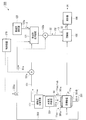
- the modified coal production facility 100 includes a drying device (drying unit) 101, a pulverized coal separation device (first pulverized coal separation unit) 111, a desulfurization agent support device ( Slurry preparation means) 121, kneading machine (kneading means) 105, molding machine (forming means) 106, control device 170, and the like.
- the drying apparatus 101 heats and drys the raw material coal 11 supplied from the receiving port in an inert gas atmosphere such as nitrogen gas (oxygen concentration of 1% or less) (110 to 200 ° C.) to remove moisture, and the moisture content rate Produces approximately 0% dry coal 11a. At this time, dry gas 11ab is also generated.
- an inert gas atmosphere such as nitrogen gas (oxygen concentration of 1% or less) (110 to 200 ° C.) (110 to 200 ° C.) (110 to 200 ° C.)
- dry gas 11ab is also generated.
- the drying device 101 for example, a rotary kiln or the like can be used.
- the delivery port of the drying device 101 communicates with the receiving port of the kneading machine 105, and the dry coal 11 a generated by the drying device 101 can be transferred to the kneading machine 105.
- the drying apparatus 101 includes a gas circulation line (circulation means) 101a whose proximal end side is connected to the delivery port side of the drying apparatus 101 and whose distal end side is connected to the receiving inlet side of the drying apparatus 101. Distribution is possible.
- pulverized coal (particle size: 300 ⁇ m or less) 11aa is accompanied by the dry gas 11ab and flows through the gas circulation line 101a together with the dry gas 11ab.
- the pulverized coal separation device 111 is provided in the gas circulation line 101a.
- the pulverized coal separation device 111 separates the pulverized coal 11aa (particle size: 300 ⁇ m or less) accompanying the dry gas 11ab from the dry gas 11ab.
- the outlet of the pulverized coal separation device 111 is connected to the inlet of the desulfurization agent support device 121 via the pulverized coal conveyance line 151.
- the pulverized coal conveyance line 151 is provided with a blower 151a and the like.
- a cyclone or a bag filter is preferably used as the pulverized coal separation device 111.
- the pulverized coal 11aa is separated from the dry gas 11ab by the cyclone, and is conveyed to the reception port of the desulfurization agent support device 121 by the pulverized coal conveyance line 151 and the blower 151a.
- a vibration device is further installed, pulverized coal 11aa is captured by the bag filter, and vibration is applied to the bag filter by the vibration device, so that the bag filter is dropped and the pulverized coal transport line 151 and the blower 151 a are conveyed to the receiving port of the desulfurization agent supporting device 121 by airflow.
- the pulverized coal 11aa may be dropped and sent from the pulverized coal separation device 111 to the desulfurization agent supporting device 121.
- the gas circulation line 101a is provided with a heat exchanger (not shown) and a blower (not shown) for adjusting the temperature of the drying gas 11ab, and a non-adjustment for adjusting the oxygen concentration of the drying gas 11ab.
- An active gas supply source (not shown) is connected. Thereby, the drying gas 11ab whose temperature and oxygen concentration are adjusted is supplied to the receiving port side of the drying apparatus 101.
- the desulfurization agent support device 121 includes, for example, a processing tank (not shown), a stirring blade (not shown), and the like.
- the desulfurization agent support device 121 is connected to the water supply source 122 and the desulfurization agent supply source 123 via the water supply line 122a and the desulfurization agent supply line 123a.
- the desulfurizing agent 2 can be supplied.
- the pulverized coal 11aa that has been conveyed to the receiving port of the desulfurization agent support device 121 is put into the treatment tank of the desulfurization agent support device 121.
- the pulverized coal 11aa put in the treatment tank, and the water 1 and the desulfurization agent 2 supplied into the treatment tank are mixed and stirred by the stirring blades of the desulfurization agent supporting device 121, and then from the desulfurization agent 2.
- the metal ions are eluted in water and come into contact with the pulverized coal 11aa, the hydroxyl ions (—OH) and carboxyl groups (—COOH) present in the pulverized coal 11aa are ion-exchanged with the metal ions.
- the slurry 12 contains modified coal (desulfurization agent-carrying coal) which is a metal-carrying coal in which the metal is carried in the above-described amount on the pulverized coal 11aa.
- a method for supporting the metal on the pulverized coal 11aa by the desulfurization agent supporting device 121 either a batch method or a distribution method can be used.
- a batch system continuous operation is possible by preparing two or more treatment tanks.
- the distribution method continuous operation is possible by using a screw conveyor or the like.
- the outlet of the desulfurizing agent support device 121 is connected to the inlet of the kneader 105 via a slurry supply line 152.
- the slurry feed line 152 is provided with a pump 152a and the like. Thereby, the slurry 12 produced
- the kneading machine 105 includes a dry coal 11a transferred from the drying device 101, a slurry 12 fed from the desulfurization agent supporting device 121 by a slurry feed line 152 and a pump 152a, and a binder supply source (not shown).
- a kneaded product 13 is generated by kneading the supplied binder 3.
- the delivery port of the kneading machine 105 communicates with the receiving port of the molding machine 106, and the kneaded material 13 generated by the kneading machine 105 can be transferred to the molding machine 106.
- the binder 3 for example, asphalt or constir can be used.
- the molding machine 106 compresses and molds the kneaded material 13 to produce briquette-shaped modified coal 14.
- the control device 170 reforms a pump (not shown) and a valve (not shown) provided in the water supply line 122a, a valve (not shown) provided in the desulfurization agent supply line 123a, a blower 151a, a pump 152a, and the like.
- Various devices of the coal production facility 100 can be controlled.
- the drying device 101 heats and drys the raw material coal 11 (110 to 200 ° C.) in an inert gas atmosphere (oxygen concentration of 1% or less) (processing step (drying process)). Process)). Thereby, dry coal 11a is generated and dry gas 11ab is generated. The dry coal 11a is transferred from the delivery port of the drying apparatus 101 to the reception port of the kneader 105. Of the dry coal 11a, pulverized coal (particle size: 300 ⁇ m or less) 11aa is accompanied by the dry gas 11ab, and flows along the gas circulation line 101a from the outlet side of the drying apparatus 101 together with the dry gas 11ab. (Circulation process).
- Dry gas 11ab and pulverized coal 11aa flowing through the gas circulation line 101a are fed to the inlet of the pulverized coal separation device 111.
- the pulverized coal separation device 111 separates the pulverized coal (particle size: 300 ⁇ m or less) 11aa from the dry gas 11ab (separation step).
- the dry gas 11ab from which the pulverized coal 11aa has been separated is adjusted in temperature and oxygen concentration by the heat exchanger and the inert gas supply source provided in the gas circulation line 101a, and further circulates through the gas circulation line 101a to be dried. 101 is fed to the receiving side.
- the pulverized coal 11aa separated from the dry gas 11ab by the pulverized coal separation device 111 is conveyed by airflow to the receiving port of the desulfurization agent support device 121 through the pulverized coal conveyance line 151 and the blower 151a.
- the pulverized coal 11aa that has been conveyed to the receiving port of the desulfurization agent support device 121 is placed in the treatment tank of the desulfurization agent support device 121.
- the treatment tank of the desulfurization agent support device 121 is supplied with water 1 via a water supply source 122 and a water supply line 122a, and with the desulfurization agent 2 via a desulfurization agent supply source 123 and a desulfurization agent supply line 123a. Supplied.
- the pulverized coal 11aa, the water 1 and the desulfurizing agent 2 are mixed and stirred by the stirring blade in the treatment tank. Thereby, the slurry 12 containing the pulverized coal carrying the desulfurizing agent (metal) 2 is generated (slurry production process).
- the slurry 12 is fed to the kneader 105 by the slurry feed line 152 and the pump 152a.
- the kneader 105 kneads the dry coal 11a, the slurry 12, and the binder 3 supplied from the binder supply source to generate a kneaded product 13 (kneading step).
- the kneaded material 13 is transferred to the molding machine 106.
- the molding machine 106 compression-molds the kneaded material 13 to produce briquette-shaped modified coal 14 (molding process).
- the pulverized coal 11aa accompanied by the dry gas 11ab is separated by the pulverized coal separation device 111 from the dry coal 11a produced by heating and drying the raw material coal 11 with the drying device 101, and the desulfurization agent supporting device.
- the slurry 12 containing pulverized coal 11aa supported by the metal of the desulfurizing agent 2 is produced by the desulfurizing agent supporting device 121, and the dry coal 11a, the slurry 12 and the binder 3 are kneaded by the kneader 105.
- Briquette-shaped modified coal 14 can be manufactured by producing the kneaded material 13, transferring the kneaded material 13 to the molding machine 106 and compression molding.
- the modified coal 14 When the modified coal 14 is combusted at a high temperature (temperature: 1500 to 1700 ° C.) and becomes exhaust gas, the metal in the modified coal 14 becomes ions, and several ions aggregate and react with oxygen to form a metal oxide.
- Nanoparticle (ultrafine particle: several to several tens of nanometers), the specific surface area is large, the reactivity is high, and the desulfurization efficiency is high as compared with a pulverized oxide (calcium oxide) of several ⁇ m. Therefore, sulfur oxide (SOx) generated during high-temperature combustion easily reacts with the metal oxide to perform in-furnace desulfurization. Since the modified coal 14 is produced by effectively using the pulverized coal 11aa generated in the process of reforming the raw material coal 11, the production yield of the modified coal 14 is improved, and the cost can be reduced.
- the solid content concentration of the slurry 12 is preferably 20 wt% to 40 wt%. This is because if the solid content concentration of the slurry 12 is lower than 20 wt%, water will come out from the kneaded product 13 by kneading by the kneader 105 and sufficient strength cannot be obtained, and the calorific value per unit weight will be reduced. This is because if the solid content concentration of the slurry 12 is higher than 40 wt%, the fluidity of the slurry 12 is lowered and the possibility of closing the slurry feed line 152 is increased. .
- the time for mixing and stirring the pulverized coal 11aa, the water 1 and the desulfurizing agent 2 in the desulfurizing agent supporting device 121 that is, the supporting time of the metal of the desulfurizing agent 2 on the pulverized coal 11aa is 0.5 to 8 hours is preferable, and 2 to 5 hours is more preferable. This is because if the loading time is shorter than 0.5 hours, the pulverized coal 11aa may not be able to carry a metal of equimolar or more with respect to the molar amount of sulfur (S) in the raw coal 11. If the loading time is longer than 8 hours, an equal mole or more metal is loaded on the pulverized coal 11aa with respect to the molar amount of sulfur (S) in the raw coal 11, and the working time is excessive. This is because the manufacturing cost is increased.
- the metal loading concentration in the metal loading coal in the slurry 12 is preferably 2 wt% to 8 wt% in a weight ratio with the pulverized coal 11aa (dry base). This is because if the metal loading concentration is lower than 2 wt%, the amount of slurry 12 kneaded with the dry coal 11a and the binder 3, that is, the amount of pulverized coal 11aa increases, resulting in an increase in production cost. This is because if the loading concentration is more than 8 wt%, it is close to saturation, so that the loading time becomes long and the manufacturing cost increases.
- the ratio of the metal-supported coal in the kneaded material 13 is preferably 1 wt% to 5 wt% in a weight ratio with respect to the total coal (dry coal 11a, pulverized coal 11aa constituting the metal-supported coal in the slurry 12). If the ratio of the metal-supported coal in the kneaded material 13 is lower than 1 wt%, the metal-supported coal may be contained to generate metal nanoparticles during high-temperature combustion and effectively reduce the effect of desulfurization. This is because if the content is higher than 5 wt%, the amount of the slurry 12, that is, the water content increases, and the amount of heat generated per unit weight may be reduced.
- the moisture content of the kneaded material 13 is preferably less than 15 wt% as a whole, and more preferably less than 10 wt%. This is because if the water content of the kneaded material 13 is higher than 15 wt%, the water is pushed out when the kneaded material 13 is molded by the molding machine 106, so that it is difficult to compress and the calorific value per unit weight is reduced. Because there is a possibility.
- an alkaline earth metal such as calcium or magnesium or a compound thereof is preferably used.
- a calcium compound such as calcium oxide (CaO), calcium carbonate (CaCO 3 ), or calcium hydroxide (Ca (OH) 2 ) is preferably used.
- magnesium source a magnesium compound such as magnesium oxide (MgO), magnesium carbonate (MgCO 3 ), or magnesium hydroxide (Mg (OH) 2 ) is preferably used.
- MgO magnesium oxide
- MgCO 3 magnesium carbonate
- Mg hydroxide Mg (OH) 2
- the ash content in the pulverized coal 11aa on which the desulfurizing agent 2 is supported is preferably 2 wt% (dry base) or less. This is because, when the ash content in the pulverized coal 11aa is more than 2 wt% (dry base), the ash content is melted and generated when the obtained modified coal is burned at high temperature (temperature: 1500 to 1700 ° C.). This is because coal ash such as fly ash (particle size: 10 ⁇ m to 20 ⁇ m) takes in the metal in the modified coal, and it is difficult to obtain an effect of increasing the desulfurization efficiency by the metal oxide nanoparticles.
- a modified coal production facility and method according to a second embodiment of the present invention will be described with reference to FIG.
- a reformer, a cooler, and an inactivation treatment apparatus are added to the reformed coal production facility according to the first embodiment described above, and pulverized coal generated by dry distillation using the dry distillation apparatus is separated.
- This is a facility to which a pulverized coal separation device and the like are added, and the other parts are generally the same as in the first embodiment.
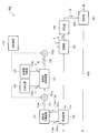
- the reformed coal production facility 200 includes the same equipment as the reformed coal production facility 100 according to the first embodiment described above, and a dry distillation device (dry distillation means) 102. , A cooler (cooling means) 103, an inactivation processing device (inactivation processing means) 104, a second pulverized coal separation device (second pulverized coal separation means) 212, a control device 270, and the like.
- the dry distillation apparatus 102, the cooler 103, and the inactivation processing apparatus 104 are disposed between the drying apparatus 101 and the kneader 105.
- the delivery port of the drying apparatus 101 is in communication with the reception port of the carbonizer 102.
- the dry distillation apparatus 102 heat-drys the dry coal 11a transferred from the drying apparatus 101 in an inert gas atmosphere (oxygen concentration of 1% or less) such as nitrogen gas (about 300 to 500 ° C.), thereby generating mercury or the like.
- the dry-distilled coal 11b from which the volatile components including are removed is generated.
- the dry distillation apparatus 102 it is preferable to use a rotary kiln or the like.
- the outlet of the carbonizer 102 communicates with the inlet of the cooler 103, so that the carbonized coal 11 b generated by the carbonizer 102 can be transferred to the cooler 103.
- generated within the dry distillation apparatus 102 can be distribute
- the pulverized coal in the dry distillation coal 11b is entrained by the gas and can be distributed to the cooler 103 together with the gas.
- the cooler 103 cools (50 to 150 ° C.) the carbonized coal 11b transferred from the carbonizer 102 in an inert atmosphere (oxygen concentration of 1% or less) to generate the cooled coal 11c.
- the outlet of the cooler 103 communicates with the receiving port of the inactivation processing device 104 so that the cooling charcoal 11 c generated by the cooler 103 can be transferred to the inactivation processing device 104.
- the gas in the cooler 103 can be distributed to the inactivation processing device 104, and the pulverized coal accompanied by the gas generated in the dry distillation apparatus 102 is also together with the gas in the cooler 103.
- the deactivation processing apparatus 104 can be distributed.
- the inactivation processing device 104 inactivates the activated surface of the cooled coal 11c transferred from the cooler 103 in an inert atmosphere (oxygen concentration of 1% or less), thereby performing surface inert coal 11d. Is generated. At this time, gas 11db is also generated.
- the delivery port of the inactivation processing apparatus 104 communicates with the receiving port of the kneading machine 105, and the surface inert coal 11 d generated by the inactivation processing apparatus 104 can be transferred to the kneading machine 105.
- the inactivation processing apparatus 105 has a proximal end side connected to the outlet side of the inactivation processing apparatus 104 and a distal end side connected to the inlet side of the inactivation processing apparatus 104 (gas circulation means).
- 104a is provided, and the gas 11db generated by the inactivation processing apparatus 104 can be circulated.
- the pulverized coal (particle size) in the inactivation processing unit 104 composed of the pulverized coal out of the surface inactive coal 11d and the pulverized coal distributed in the inactivation processing unit 104 with the gas in the cooler 103. : 300 ⁇ m or less) 11da is accompanied by the gas 11db and flows through the gas circulation line 104a together with the gas 11db.
- the second pulverized coal separation device 212 is provided in the gas circulation line 104a.
- the second pulverized coal separation device 212 separates the pulverized coal 11da (particle size: 300 ⁇ m or less) accompanying the gas 11db from the gas 11db containing the gas generated by the dry distillation apparatus 102.
- the outlet of the second pulverized coal separation device 212 is connected to the inlet of the desulfurization agent support device 121 via the pulverized coal conveyance line 253.
- the pulverized coal transport line 253 is provided with a blower 253a and the like.
- the second pulverized coal separation device 212 for example, a cyclone or a bag filter can be used as in the pulverized coal separation device 111 described above.
- the pulverized coal 11da accompanied by the gas 11db is separated from the gas 11db by the second pulverized coal separation device 212, and is conveyed to the reception port of the desulfurization agent support device 121 by the pulverized coal conveyance line 253 and the blower 253a which are conveying means.
- the pulverized coal 11da may be dropped and sent from the second pulverized coal separation device 212 to the desulfurization agent supporting device 121.
- the gas circulation line 104a described above is provided with a heat exchanger (not shown) and a blower (not shown) for adjusting the temperature of the circulating gas 11db to adjust the oxygen concentration of the gas 11db.
- An inert gas supply source (not shown) is connected. As a result, the gas 11db whose temperature and oxygen concentration are adjusted is supplied to the receiving side of the inactivation processing apparatus 104.
- the pulverized coal 11da that has been conveyed to the receiving port of the desulfurization agent support device 121 is also put into the treatment tank of the desulfurization agent support device 121.
- the pulverized coals 11aa and 11da put in the treatment tank and the water 1 and the desulfurization agent 2 supplied into the treatment tank are mixed and stirred by the stirring blades of the desulfurization agent supporting device 121, and the desulfurization agent
- metal ions When metal ions are eluted from water 2 and come into contact with the pulverized coals 11aa and 11da, hydrogen ions of hydroxyl groups (—OH) and carboxyl groups (—COOH) present in the pulverized coals 11aa and 11da and the metal ions are ion-exchanged to form a slurry 22 containing modified coal (desulfurization agent-supported coal) which is a metal-supported coal in which the metal is supported on the pulverized coal 11aa and 11da
- the kneading machine 105 includes a surface inert coal 11d transferred from the deactivation processing device 104, a slurry 22 fed from the desulfurization agent support device 121 by the slurry feed line 152 and the pump 152a, and a binder supply source ( The kneaded material 23 is produced
- the control device 270 can control various devices included in the modified coal manufacturing facility 200 such as the blower 235a in addition to the various devices included in the modified coal manufacturing facility 100.
- the dry coal 11 a generated by supplying the raw material coal 11 to the drying apparatus 101 is transferred from the delivery port of the drying apparatus 101 to the receiving port of the dry distillation apparatus 102.
- the dry coal 11a transferred to the receiving port of the dry distillation apparatus 102 is heated to dry distillation (around 300 to 500 ° C.) in an inert gas atmosphere (oxygen concentration of 1% or less) to become dry distillation coal 11b (processing step). (Dry distillation step)), and transferred from the delivery port of the carbonization device 102 to the reception port of the cooler 103.
- the dry-distilled coal 11b transferred to the inlet of the cooler 103 is cooled to become cooled coal 11c (50 to 150 ° C.) (processing step (cooling step)), and is discharged from the outlet of the cooler 103. It is transferred to the receiving port of the activation processing device 104.
- the surface of the cooling coal 11c transferred to the receiving port of the inactivation processing device 104 is inactivated to become surface inactive coal 11d (processing step (inactivation processing step)), and the inactive
- the material is transferred from the delivery port of the chemical conversion apparatus 104 to the reception port of the kneader 105.
- the gas generated when the dry coal 11a is heated and distilled in the carbonizer 102 is circulated through the cooler 103 to the inactivation treatment device 104, and the dry coal 11b, the cooled coal 11c, and the surface inert coal 11d.
- the pulverized coal 11da is accompanied by the gas 11db generated in the inactivation processing apparatus 104.
- the gas 11db flows through the gas circulation line 104a from the delivery port side of the inactivation processing device 104 together with the pulverized coal 11da.
- the gas 11db and pulverized coal 11da flowing through the gas circulation line 104a are supplied to the receiving port of the second pulverized coal separation device 212.
- the second pulverized coal separation device 212 separates pulverized coal (particle size: 300 ⁇ m or less) 11da from the gas 11db (second pulverized coal separation step).
- the gas 11db separated from the pulverized coal 11da is inactivated by adjusting the temperature and oxygen concentration by the heat exchanger and the inert gas supply source provided in the gas circulation line 104a, and further circulating through the gas circulation line 104a. It is fed to the receiving side of the processing device 104.
- the pulverized coal 11da separated from the gas 11db by the second pulverized coal separation device 212 is air-flowed to the inlet of the desulfurization agent support device 121 by the pulverized coal conveyance line 253 and the pump 253a (conveying step).
- the pulverized coals 11aa and 11da that have been conveyed to the receiving port of the desulfurization agent support device 121 are put into the treatment tank of the desulfurization agent support device 121.
- the treatment tank of the desulfurization agent support device 121 is supplied with water 1 via a water supply source 122 and a water supply line 122a, and with the desulfurization agent 2 via a desulfurization agent supply source 123 and a desulfurization agent supply line 123a. Supplied.
- the pulverized coal 11aa, 11da, the water 1 and the desulfurizing agent 2 are mixed and stirred by the stirring blade in the treatment tank. Thereby, the slurry 22 containing the pulverized coal carrying the desulfurizing agent (metal) 2 is produced (slurry production process).
- the slurry 22 is fed to the kneader 105 by a slurry feed line 152 and a pump 152a.
- the kneading machine 105 kneads the surface inert coal 11d, the slurry 22, and the binder 3 supplied from the binder supply source to generate a kneaded product 23 (kneading step).
- the kneaded material 23 is transferred to the molding machine 106.
- the molding machine 106 compression-molds the kneaded material 23 to produce briquette-shaped modified coal 24 (molding process).
- the pulverized coal 11aa accompanied by the dry gas 11ab is separated by the pulverized coal separation device 111 from the dry coal 11a produced by heating and drying the raw material coal 11 with the drying device 101, and the desulfurization agent supporting device.
- the pulverized coal 11da accompanied by the gas 11db of the surface inert coal 11d generated by the inert treatment by the 104 is separated by the second pulverized coal separation device 212 and is conveyed to the desulfurization agent support device 121 by airflow, and the desulfurization agent support device 121.
- the slurry 22 containing pulverized coal 11aa and 11da supported by the metal of the desulfurizing agent 2 is prepared, and the surface is inactive.
- the charcoal 11d, the slurry 22 and the binder 3 are kneaded by a kneader 105 to produce a kneaded product 23, and the kneaded product 23 is transferred to a molding machine 106 and compression molded to produce a briquette-shaped modified coal 24. be able to.
- a high temperature temperature: 1500 to 1700 ° C.
- the metal in the reformed coal 24 becomes ions, and several ions aggregate and react with oxygen to form a metal oxide.
- Nanoparticle (ultrafine particle: several to several tens of nanometers), the specific surface area is large, the reactivity is high, and the desulfurization efficiency is high as compared with a pulverized oxide (calcium oxide) of several ⁇ m. Therefore, sulfur oxide (SOx) generated during high-temperature combustion easily reacts with the metal oxide to perform in-furnace desulfurization. Since the modified coal 24 is produced by effectively using the pulverized coals 11aa and 11da generated in the process of reforming the raw material coal 11, the production yield of the modified coal 24 is improved, and the cost can be reduced. .
- the solid content concentration of the slurry 22 is preferably 20 wt% to 40 wt% for the same reason as in the first embodiment.
- the time for mixing and stirring the pulverized coal 11aa, 11da, the water 1 and the desulfurizing agent 2 in the desulfurizing agent supporting device 121 (the time for loading the metal of the desulfurizing agent on the pulverized coal 11aa, 11da) is 0.5-8. Time is preferred.
- the metal loading concentration in the metal loading coal in the slurry 22 is preferably 2 wt% to 8 wt% in a weight ratio with the pulverized coal 11aa, 11da (dry base).
- the ratio of the metal-supported coal in the kneaded material 23 is 1 wt% to 5 wt% in a weight ratio with respect to the total coal (surface inert coal 11d, pulverized coal 11aa and 11da constituting the metal-supported coal in the slurry 22). Is preferred.
- the moisture content of the kneaded material 23 is preferably less than 15 wt% as a whole, and more preferably less than 10 wt%.
- the ash content in the pulverized coals 11aa and 11da, that is, the ash content in the slurry 22 is preferably 2 wt% (dry base) or less.
- the drying apparatus included in the modified coal production facility according to the first embodiment described above is specified as an apparatus that indirectly heats with steam, and the modified coal production facility according to the first embodiment
- the apparatus is provided with a steam supply source, a steam supply line, a drain pipe, and the like, and the rest is substantially the same as in the first embodiment.
- the modified coal production facility 300 is indirectly connected with steam 61 instead of the drying device 101 included in the modified coal production facility 100 according to the first embodiment described above. Is provided with a drying device 301 for heating and drying the raw coal 11.
- the modified coal production facility 300 further includes a steam supply source 331, a steam supply line 331a, a drain pipe 332, a control device 370, and the like.
- the drying device 301 includes a rotatable inner cylinder 301A, an outer cylinder 301B that covers the outer side of the inner cylinder 301A, and a gas circulation line (circulation means) 301a.
- the outer cylinder 301B is connected to a water vapor supply source 331 via a water vapor supply line 331a.
- a proximal end side of a drain pipe 332 that communicates with the treatment tank of the desulfurization agent support device 121 is connected to the outer cylinder 301B.
- the raw material coal 11 supplied to one end side (base end side) of the inner cylinder 301A is moved to the other end side (leading end side) of the inner cylinder 301A while being stirred as the inner cylinder 301A rotates. become.
- the raw material coal 11 in the inner cylinder 301A is indirectly heated by the water vapor 61 supplied into the outer cylinder 301B, and the water content is almost 0 at the other end side of the inner cylinder 301A. % Dry coal 11a.
- the drying apparatus 301 is connected to the outlet side of the drying apparatus 301 on the proximal end side and to the receiving side of the drying apparatus 301 on the distal end side, similarly to the drying apparatus 101 included in the modified coal production facility 100 described above.
- a gas circulation line 301a is provided, and the dry gas 11ab generated by the drying device 301 can be circulated.
- the dry coal 11a pulverized coal (particle size: 300 ⁇ m or less) 11aa is accompanied by the dry gas 11ab and flows through the gas circulation line 301a together with the dry gas 11ab.
- the gas circulation line 301a is provided with a heat exchanger (not shown) and a blower (not shown) for adjusting the temperature of the dry gas 11ab, and a non-adjustable device for adjusting the oxygen concentration of the dry gas 11ab.
- An active gas supply source (not shown) is connected.
- the control device 370 can control various devices included in the modified coal production facility 300 such as the valve 332a in addition to the various devices included in the modified coal production facility 100.
- the drain pipe 332, the valve 332a and the like constitute a drain means, and the valve 332a and the like constitute a feed amount adjusting means.
- the drying apparatus 301 uses the steam 61 supplied into the outer cylinder 301B of the drying apparatus 301 via the steam supply source 331 and the steam supply line 331a.
- the raw material coal 11 is heated and dried (around 110 to 200 ° C.) in an inert gas atmosphere (oxygen concentration of 1% or less) (processing step (drying step)) to produce dry coal 11a and dry gas 11ab Is generated.
- pulverized coal (particle size: 300 ⁇ m or less) 11aa is accompanied by the dry gas 11ab and circulates through the gas circulation line 301a from the outlet side of the drying device 301 together with the dry gas 11ab. (Circulation process).
- the pulverized coal 11aa (particle size: 300 ⁇ m or less) entrained in the dry gas 11ab is separated from the dry gas 11ab by the pulverized coal separation device 111 (first pulverized coal separation step), and desulfurized by the pulverized coal transport line 151 and the blower 151a.
- the air is conveyed to the receiving port of the agent carrying device 121 and is put into the treatment tank of the desulfurizing agent carrying device 121.
- the dry gas 11ab separated from the pulverized coal 11aa is adjusted in temperature and oxygen concentration by the heat exchanger and the inert gas supply source provided in the gas circulation line 301a, and further circulates through the gas circulation line 301a. It is fed to the receiving side of the drying device 301.
- the treatment tank of the desulfurization agent support device 121 is supplied with the desulfurization agent 2 via the desulfurization agent supply source 123 and the desulfurization agent supply line 123a, and the steam 61 is supplied to the inner cylinder 301A by the drain pipe 332 and the valve 332a. Drain water (90 to 100 ° C.) 61a generated by heating and cooling is supplied (drain process). At this time, the supply amount of the drain water 61a to the treatment tank of the desulfurization agent support device 121 is adjusted by the valve 332a or the like (feed amount adjustment step).
- the pulverized coal 11aa, the drain water 61a, and the desulfurizing agent 2 are mixed and stirred by the stirring blade in the treatment tank to become a slurry 32 containing pulverized coal carrying the desulfurizing agent (metal) 2 ( Slurry manufacturing process).
- the slurry 32 is fed to the kneader 105 by the slurry feed line 152 and the pump 152a.
- the kneader 105 kneads the dry coal 11a, the slurry 32, and the binder 3 supplied from the binder supply source to generate a kneaded product 33 (kneading step).
- the kneaded product 33 is transferred to the molding machine 106.
- the molding machine 106 compression-molds the kneaded material 33 to produce a briquette-shaped modified coal 34 (molding process).
- the drying device 301 is an apparatus for indirectly heating and drying the raw coal 11 with the steam 61, and the drain generated by the steam 61 being cooled by the indirect heating of the raw coal 11.
- the desulfurization agent support device 121 can use drain water 61a having a temperature higher than that of normal water (normal temperature). Compared with the case of using water, the loading speed of the desulfurizing agent on the pulverized coal 11aa is faster, and the metal-supported coal in the slurry 32 is generated faster than the case of using normal water (normal temperature).
- a processing tank can be reduced in size.
- the temperature of normal (water) fluctuates depending on the season, etc., and the loading speed varies accordingly.
- the drain water 61a is stable without changing the temperature depending on the season, the metal to the pulverized coal is stable.
- the loading speed is stable, and the slurry 32 containing homogeneous metal-supporting coal can be generated. Therefore, the desulfurization rate when the reformed coal 34 is burned at a high temperature can be stabilized.
- a modified coal production facility and method according to a fourth embodiment of the present invention will be described with reference to FIG.
- This embodiment is a facility in which a modified coal feed line, a raw material coal (heterogeneous coal type) supply line, a mixer, etc. are added to the modified coal production facility according to the first embodiment described above, Except this, it is almost the same as the first embodiment.
- the modified coal production facility 400 includes the same equipment as the modified coal production facility 100 according to the first embodiment described above, and the modified coal feed line 454. , A raw material coal supply line 455, a mixer (mixing means) 461, a control device 470, and the like.
- the reformed coal feed line 454 is provided in such a manner that the base end side communicates with the feed port of the molding machine 106.
- the leading end side of the reformed coal feed line 454 communicates with the receiving port of the mixer 461.
- the raw material coal supply line 455 is provided in such a manner that the tip side communicates with the inlet of the mixer 461.
- the mixer 461 mixes the reformed coal 14 supplied through the reformed coal supply line 454 and the raw coal 41 supplied through the raw coal supply line 455 to generate the mixed coal 45.
- a coal type B different from the raw material coal 11 which is less likely to carry the desulfurization agent (metal) 2 by an ion exchange method than the raw material coal 11, is used. It is possible.
- the control device 470 can control various devices included in the modified coal production facility 400 such as a mixer 461 in addition to the various devices included in the modified coal production facility 100.
- the drying device 101 When the raw material coal 11 (coal type A) is supplied to the drying device 101, the drying device 101, the pulverized coal separation device 111, the desulfurization agent support device 121, the kneading machine 105, and the molding are the same as the modified coal manufacturing facility 100 described above.
- the reformed coal 14 is manufactured by the machine 106 and the like, and the reformed coal 14 is fed to the mixer 461 through the reformed coal feed line 454.
- Raw material coal 41 (coal type B) is supplied to the mixer 461 through a raw material coal supply line 455.
- the mixer 461 mixes the reformed coal 14 fed by the reformed coal feed line 454 and the raw coal 41 supplied by the raw coal feed line 455 to generate the mixed coal 45 (mixing step).
- the reformed coal feed line 454, the raw coal supply line 455, and the mixer 461 are provided, and the reformed coal 14 supplied by the reformed coal feed line 454, and the raw coal Since the mixed coal 45 can be produced by mixing the raw coal 41 supplied by the supply line 455 with the mixer 461, the coal that does not easily carry the desulfurizing agent 2 can be used as the raw coal 41.
- the modified coal 14 is produced only from the raw material coal 11 that is easy to carry, more various types of coal can be used effectively.
- the mixing ratio of the reformed coal 14 and the raw coal 41 is the same as the ratio of the metal-supported coal in the kneaded product 13 to the total coal (the dry coal 11a and the metal-supported coal in the slurry 12).
- the weight ratio of the pulverized coal 11aa and the raw coal 41) is preferably 1 wt% to 5 wt%.
- the ash content in the pulverized coal 11aa, that is, the ash content in the slurry 12 is preferably 2 wt% (dry base) or less for the same reason as in the first embodiment.
- a modified coal production facility and method according to a fifth embodiment of the present invention will be described with reference to FIG.
- This embodiment is a facility in which the drying apparatus provided in the modified coal production facility according to the first embodiment described above is changed to a device with a pulverizer, and an ash separator and a separator are added. Except this, it is almost the same as the first embodiment.
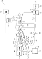
- the modified coal production facility 500 includes the same equipment as the modified coal production facility 100 according to the first embodiment described above, and a drying device (processing means) 501.
- the drying apparatus 501 is an apparatus in which a dryer (drying means) 501A and a pulverizer (pulverization means) 501B are integrated, and pulverizes the raw material coal 11 supplied from the receiving port (for example, particle size: 300 ⁇ m or less). At the same time, it is dried by heating (for example, 110 to 200 ° C) in an inert gas atmosphere such as nitrogen gas (oxygen concentration of 1% or less), and moisture is removed to produce dry coal with a moisture content of almost 0%. To do. At this time, dry gas 11ab is also generated, and pulverized coal 11ba and 11bb having a large specific gravity are also generated.
- an inert gas atmosphere such as nitrogen gas (oxygen concentration of 1% or less)
- the drying device 501 includes a gas circulation line (circulation means) 501a whose proximal end side is connected to the delivery port side of the drying device 501, and whose distal end side is connected to the receiving port side of the drying device 501, and the drying gas 11ab is Distribution is possible.
- a pulverized coal separation device 111 is provided in the gas circulation line 501a.
- pulverized coal (particle size: 300 ⁇ m or less) 11aa is accompanied by the dry gas 11ab and flows through the gas circulation line 501a together with the dry gas 11ab.
- the gas circulation line 501a is provided with a heat exchanger (not shown) and a blower (not shown) for adjusting the temperature of the drying gas 11ab, and an inert gas for adjusting the oxygen concentration of the drying gas 11ab.
- a supply source (not shown) is connected.
- a lower delivery port provided in the lower portion communicates with a receiving port of the ash separation device 513 through a drop discharge line 501b, and the pulverized coals 11ba and 11bb generated by the drying device 501 have a high specific gravity.
- the separator 513 can be fed.
- the drop discharge line 501b and the like constitute a drop discharge means.
- the ash separator 513 separates the pulverized coal 11ba and 11bb having a large specific gravity fed from the receiving port into a pulverized coal having a high ash concentration (a pulverized coal containing pyrite sulfur and the like) 11bb and a pulverized coal 11ba having a low ash concentration. Then, the pulverized coal 11bb is removed.
- the ash separator 513 is connected to the drying device 501 via a feed line 501c, and the pulverized coal 11ba is returned to the drying device 501 via the feed line 501c.
- the ash separation device 513 include a magnetic separation device (magnetic separation means) that separates by magnetism, a specific gravity separation device (specific gravity separation means) that separates by a specific gravity difference, and the like.
- Separation device 514 is provided connected to pulverized coal conveyance line 151.
- the separation device 514 is connected to the receiving port of the desulfurization agent support device 121 via the first pulverized coal feeding line 555 and is connected to the receiving port of the kneader 105 via the second pulverized coal feeding line 556. ing.
- the control device 570 can control various devices included in the modified coal production facility 500 in addition to the various devices included in the modified coal production facility 100.
- the drying apparatus 501 pulverizes the raw material coal 11 in an inert gas atmosphere (oxygen concentration of 1% or less) (a pulverization step) and heat-drys (drying step).
- generating dry coal (pulverized coal) 11aa, 11ba, 11bb dry gas 11ab produces
- pulverized coal particle size: 300 ⁇ m or less
- 11aa is accompanied by the dry gas 11ab, and together with the dry gas 11ab, the gas circulation line 501a from the outlet side of the drying device 501. Circulate.
- Pulverized coal having a large specific gravity among the dry coals 11aa, 11ba, 11bb (specific gravity not to be accompanied by the dry gas 11ab, for example, specific gravity: 1.4 or more) 11ba, 11bb is sent from the lower outlet of the drying device 501. It is discharged and fed to the receiving port of the ash separator 513 through the drop discharge line 501b (fall discharge step).
- the dry coal (pulverized coal) 11ba and 11bb fed to the inlet of the ash separator 513 is separated into pulverized coal 11bb having a high ash concentration and pulverized coal 11ba having a low ash concentration, and the pulverized coal 11bb is removed.
- the pulverized coal 11ba is returned to the drying device 501 via the feed line 501d (ash separation step), and is pulverized again by the drying device 501 and dried by heating. That is, when a magnetic separator is used as the ash separator 513, the pulverized coals 11ba and 11bb are pulverized coal containing pyrite sulfur by magnetism (magnetic pulverized coal).
- the pulverized coal 11ba is separated from the pulverized coal 11ba having a low ash concentration, which is a pulverized coal containing no pyrite sulfur, and the pulverized coal 11bb is removed from the pulverized coal 11ba and 11bb (magnetic separation step).
- a specific gravity separator is used as the ash separator 513
- the pulverized coals 11ba and 11bb are pulverized coal containing pyrite sulfur or the like (pulverized coal having a relatively high specific gravity) due to a difference in specific gravity.
- the pulverized coal 11bb is removed from the pulverized coal 11ba and 11bb by being separated into the pulverized coal 11ba and the pulverized coal 11ba having a low ash concentration, which is other pulverized coal (pulverized coal having a relatively small specific gravity). Separation step).
- Dry gas 11ab and pulverized coal 11aa flowing through the gas circulation line 501a are supplied to the inlet of the pulverized coal separation device 111.
- the pulverized coal separation device 111 separates pulverized coal (particle size: 300 ⁇ m or less) 11aa from the dry gas 11ab (first pulverized coal separation step).
- the drying gas 11ab from which the pulverized coal 11aa has been separated is adjusted in temperature and oxygen concentration by the heat exchanger and the inert gas supply source provided in the gas circulation line 501a, and further circulates through the gas circulation line 501a to be a drying device.
- 501 is fed to the receiving side.
- the pulverized coal 11aa separated by the pulverized coal separation device 111 is conveyed by airflow to the receiving port of the separation device 514 through the pulverized coal conveyance line 151 and the blower 151a.
- the pulverized coal 11aa that has been conveyed to the receiving port of the separation device 514 is separated by the separation device 514, and the pulverized coal 11aa that is part of the pulverized coal 11aa is supported by the desulfurization agent via the first pulverized coal feed line 555.
- the pulverized coal 11aa that is the remainder of the pulverized coal 11aa is fed to the inlet of the kneader 105 via the second pulverized coal feed line 556 (pulverized coal separation and feeding step). ).
- the pulverized coal 11aaa fed to the receiving port of the desulfurization agent support device 121 is put into the treatment tank of the desulfurization agent support device 121.
- the treatment tank of the desulfurization agent support device 121 is supplied with water 1 via a water supply source 122 and a water supply line 122a, and with the desulfurization agent 2 via a desulfurization agent supply source 123 and a desulfurization agent supply line 123a. Supplied.
- the pulverized coal 11aaa, the water 1 and the desulfurizing agent 2 are mixed and stirred by the stirring blade in the treatment tank to become a slurry 52 containing pulverized coal carrying the desulfurizing agent (metal) 2 (slurry). Production process).
- the slurry 52 is fed to the kneader 105 by the slurry feed line 152 and the pump 152a.
- the kneader 105 kneads the slurry 52, the pulverized coal 11aab, and the binder 3 supplied from the binder supply source to generate a kneaded product 53 (kneading step).
- the kneaded product 53 is transferred to the molding machine 106.
- the molding machine 106 compression-molds the kneaded material 53 to produce briquette-shaped modified coal 54 (molding process).
- the specific gravity of the dry coal produced by pulverizing the raw material coal 11 and drying by heating with the drying device 501 is high.
- the large pulverized coal is dropped and discharged and fed to the ash separator 513, and the pulverized coal 11bb having a high ash concentration is removed by the ash separation by the ash separator 513, so that the pulverized coal by the drying device and the heat drying and the ash separator are used.
- the sulfur content contained in the modified coal 54 can be reduced.
- the ash content in the raw coal 11 is removed as the pulverized coal 11bb by the ash separator 513, and the pulverized coal 11aaa carrying the desulfurizing agent 2 contains almost no ash, the ash content of the raw coal 11 is not limited. Compared with the case where modified coal is produced without using the ash separation device 513 with the raw material coal having a low ash content, coal having a large content can be used as the raw material coal 11. Can be used effectively.
- the solid content concentration of the slurry 52 is 20 wt% to 40 wt% for the same reason as in the first embodiment.
- the time for mixing and stirring the pulverized coal 11aaa, the water 1 and the desulfurizing agent 2 in the desulfurizing agent supporting device 121 (the time for supporting the metal of the desulfurizing agent on the pulverized coal 11aaa) is 0.5 to 8 hours. Is preferred.
- the metal loading concentration of the metal-loaded coal in the slurry 52 is preferably 2 wt% to 8 wt% in weight ratio with the pulverized coal 11aaa (dry base) (the loading ratio of the desulfurizing agent is 30 to 90% of the saturation loading ratio). Is preferable).
- the ratio of the metal-supported coal in the kneaded material 53 is preferably 1 wt% to 5 wt% in terms of the weight ratio with respect to the total coal (pulverized coal 11aaa constituting the metal-supported coal in the slurry 52).
- the moisture content of the kneaded product 53 is preferably less than 15 wt% as a whole, and more preferably less than 10 wt%.
- FIG. 10 A modified coal production facility and method according to a sixth embodiment of the present invention will be described with reference to FIG.
- the present embodiment is a facility in which the arrangement of the pulverized coal separation device and the ash separation device included in the modified coal production facility according to the fifth embodiment described above is changed, and the rest is generally the fifth embodiment. It has become the same.
- the modified coal production facility 600 includes the same equipment as the modified coal production facility 500 according to the fifth embodiment described above, and a pulverized coal feed line 657, An ash separation pulverized coal feed line 658, a control device 670, and the like are provided.
- the pulverized coal separation device 111 is provided in a gas circulation line (circulation means) 501a, and a delivery port is connected to a receiving port of the kneader 105 via a pulverized coal feed line 657.
- the ash separator 513 is provided in the fall discharge line 501b, and the outlet is connected to the inlet of the desulfurization agent carrier 121 via the ash separation pulverized coal feed line 658.
- the pulverized coal feed line 657 and the ash separation pulverized coal feed line 658 are provided with blowers 657a and 658a, respectively. Note that the pulverized coal feed line 657 and the blower 657a constitute pulverized coal feed means.
- the ash-separated pulverized coal feeding line 658, the blower 658a, and the like constitute ash-separated pulverized coal feeding means.
- the control device 670 can control various devices included in the modified coal production facility 600 such as the blowers 657a and 658a in addition to the various devices included in the modified coal production facility 500.
- the pulverized coal 11aa separated by the pulverized coal separation device 111 is fed to the inlet of the kneader 105 by the pulverized coal feeding line 657 and the blower 657a (pulverized coal feeding process).
- the pulverized coal 11ba separated by the ash separation device 513 is fed to the inlet of the desulfurization agent support device 121 by the ash separation pulverized coal feeding line 658 and the blower 658a (ash separation pulverized coal feeding step).
- the pulverized coal 11ba fed to the receiving port of the desulfurizing agent supporting device 121 is put into the processing tank of the desulfurizing agent supporting device 121.
- the treatment tank of the desulfurization agent support device 121 is supplied with water 1 via a water supply source 122 and a water supply line 122a, and with the desulfurization agent 2 via a desulfurization agent supply source 123 and a desulfurization agent supply line 123a. Supplied.
- the pulverized coal 11ba, the water 1 and the desulfurizing agent 2 are mixed and stirred by the stirring blade in the treatment tank to become a slurry 62 containing pulverized coal carrying the desulfurizing agent (metal) 2 (slurry). Production process).
- the slurry 62 is fed to the kneader 105 by the slurry feed line 152 and the pump 152a.
- the kneader 105 kneads the slurry 62, the pulverized coal 11aa, and the binder 3 supplied from the binder supply source to generate a kneaded product 63 (kneading step).
- the kneaded product 63 is transferred to the molding machine 106.
- the molding machine 106 compression-molds the kneaded material 63 to produce briquette-shaped modified coal 64 (molding process).
- an apparatus for separating the pulverized coal from supporting the desulfurizing agent and kneading is not required.
- the apparatus and processing can be simplified. Thereby, manufacturing cost can be reduced.
- the solid content concentration of the slurry 62 is 20 wt% to 40 wt% for the same reason as in the fifth embodiment.
- the time for mixing and stirring the pulverized coal 11ba, the water 1 and the desulfurizing agent 2 in the desulfurizing agent supporting device 121 (the time for supporting the metal of the desulfurizing agent on the pulverized coal 11ba) is set to 0.5 to 8 hours. Is preferred.
- the metal support concentration in the metal support coal in the slurry 62 is 2 wt% to 8 wt% in weight ratio with the pulverized coal 11ba (dry base) (the desulfurization agent support ratio is 30 to 90% of the saturation support ratio). Is preferable).
- the ratio of the metal-supported coal in the kneaded product 63 is preferably 1 wt% to 5 wt% in a weight ratio with respect to the total coal (pulverized coal 11ba constituting the metal-supported coal in the slurry 62).
- the moisture content of the kneaded product 63 is preferably less than 15 wt% as a whole, and more preferably less than 10 wt%.
- a modified coal production facility and method according to a seventh embodiment of the present invention will be described with reference to FIG.
- the present embodiment is a facility in which the water supply source provided in the modified coal production facility according to the fifth embodiment described above is changed, and is otherwise substantially the same as the fifth embodiment.
- the modified coal production facility 700 includes the same equipment as the modified coal production facility 500 according to the fifth embodiment described above, and also includes a control device 770 and condensed water separation. A device 780 and the like are further provided.
- the condensate separation device 780 includes a condensate separator 781 provided with an upper connection to the gas circulation line 501a, a water storage tank 783 connected via a condensate separator 781 and a condensate discharge pipe 782, and a water storage A base end portion is connected to the lower portion of the tank 783, and a condensed water supply pipe 784 is connected to the desulfurization agent support device 121.
- the condensed water discharge pipe 782 is provided with a flow rate adjusting valve 782a.
- the condensed water supply pipe 784 is provided with a pump 784a.
- the condensate separator 780 further includes a condensate separator 785 provided with the upper part connected to the atmospheric discharge pipe 501e connected to the gas circulation line 501a.
- the condensed water separator 785 is connected to the water storage tank 783 via the condensed water discharge pipe 786.
- the atmospheric discharge pipe 501e and the condensed water discharge pipe 786 are provided with flow rate adjusting valves 501ea and 786a, respectively.
- the condensed water separator 780 and the like constitute condensed water separation means.
- the control device 770 can control various devices included in the modified coal production facility 700 such as flow rate adjusting valves 501ea, 782a, 786a and a pump 784a in addition to the various devices included in the modified coal production facility 500. .
- the pulverized coal 11aaa fed to the receiving port of the desulfurization agent support device 121 is put into the treatment tank of the desulfurization agent support device 121.
- the treatment tank of the desulfurization agent support device 121 is supplied with the desulfurization agent 2 via the desulfurization agent supply source 123 and the desulfurization agent supply line 123a, and the condensed water separator 780 supplies the dry gas 11ab to the gas circulation line.
- Condensed water (90 to 100 ° C.) 71 is generated by cooling with 501a and the atmospheric discharge pipe 501e, and this condensed water 71 is separated and fed (condensed water separation step). At this time, the feed amount of the condensed water 71 to the treatment tank of the desulfurization agent support device 121 is adjusted by the pump 784a or the like.
- the pulverized coal 11aa, the condensed water 71, and the desulfurizing agent 2 are mixed and stirred by the stirring blade in the processing tank to become a slurry 72 containing pulverized coal carrying the desulfurizing agent (metal) 2 ( Slurry manufacturing process).
- the slurry 72 is fed to the kneader 105 by the slurry feed line 152 and the pump 152a.
- the kneader 105 kneads the slurry 72, the pulverized coal 11aab, and the binder 3 supplied from the binder supply source to generate a kneaded product 73 (kneading step).
- the kneaded product 73 is transferred to the molding machine 106.
- the molding machine 106 compression-molds the kneaded material 73 to produce briquette-shaped modified coal 74 (molding process).
- the gas circulation line 501a is provided by including the condensed water separator 780.
- the condensed water 71 generated in the atmospheric discharge pipe 501e can be used as a raw material for the slurry 72.
- the modified coal 74 can be produced even in a harsh environment for obtaining water for slurry production.
- the solid content concentration of the slurry 72 is 20 wt% to 40 wt% for the same reason as in the fifth embodiment.
- the time for mixing and stirring the pulverized coal 11aa, the water 71 and the desulfurizing agent 2 in the desulfurizing agent supporting device 121 (the time for supporting the metal of the desulfurizing agent on the pulverized coal 11aaa) is 0.5 to 8 hours. Is preferred.
- the metal loading concentration in the metal-loaded coal in the slurry 72 is preferably 2 wt% to 8 wt% in weight ratio with the pulverized coal 11aaa (dry base) (the loading ratio of the desulfurizing agent is 30 to 90% of the saturated loading ratio). Is preferable).
- the ratio of the metal-supported coal in the kneaded product 73 is preferably 1 wt% to 5 wt% in a weight ratio with respect to the total coal (pulverized coal 11aaa constituting the metal-supported coal in the slurry 72).
- the total water content of the kneaded product 73 is preferably less than 15 wt%, and more preferably less than 10 wt%.
- the modified coals 14 and 24 having the slurries 12 and 22 including the desulfurization agent-supporting coal in which the desulfurization agent 2 is supported only on the pulverized coals 11aa and 11da generated by heat-treating the raw coal 11 are produced.
- pulverizes the raw material coal 11 with a mill etc. is produced. It is also possible to do. Even in such a case, the same effects as the above-described modified coal production facility can be obtained.
- modified coal production facilities 100 and 300 in which the pulverized coal separation devices 111 and 111 are provided in the gas circulation lines 101a and 301a have been described.
- a modified coal production facility provided with a pulverized coal separator is also possible.
- the modified coal production facility 200 provided with the second pulverized coal separation device 212 in the gas circulation line 104a has been described.
- the second pulverized coal is disposed in the exhaust line for discharging the gas generated in the inactivation processing device 104. It is also possible to use a modified coal production facility provided with a separation device.
- the slurry 12 and the binder 3 are kneaded in the kneader 105 to obtain the kneaded product 13, and the reformed coal 14 obtained by forming the kneaded product 13 into a briquette shape in the molding machine 106 and the raw coal 41 are mixed in the mixer 461.
- the modified coal production facility 400 for producing the mixed coal 45 that is mixed in the above-described manner has been described. However, the raw coal 41 is pulverized, and the pulverized raw coal 41, the slurry 12, and the binder 3 are added to the kneader 105.
- the pulverized coal 11aa is supplied to the desulfurization agent supporting device 121.
- the pulverized coal 11aa is removed from the pulverized coal 11aa which is the support for the desulfurizing agent 2. It is preferable.
- the pulverized coal 11aa can be supported on the pulverized coal 11aa having a low ash concentration, from which the pulverized coal 11aa having a high ash concentration has been removed, by simply treating the pulverized coal 11aa with the ash separator 513.
- the ash separator 513 There is no restriction on the ash content of 11, and coal with a high ash content can be used as the raw coal 11.
- the raw coal with a low ash content is used to produce modified coal without the ash separator 513. Compared to the case, more various types of coal can be used effectively.
- the test body had a higher desulfurization rate than the comparative body. Since the desulfurization rate of the specimen is 40% when the calcium / sulfur (molar ratio) is 0.5, when the calcium / sulfur (molar ratio) is 1, the desulfurization rate of the specimen is 80%. It was speculated.
- coal and calcium carbonate particles size of 2 ⁇ m to 10 ⁇ m
- the desulfurization rate is improved as compared with the case where the mixture is blown into the furnace and burned at high temperature.
- the modified coal production facility and method according to the present invention can produce modified coal capable of generating ultrafine particles of a desulfurization agent at high temperature combustion at low cost, and can be used extremely beneficially industrially.
Landscapes
- Chemical & Material Sciences (AREA)
- Oil, Petroleum & Natural Gas (AREA)
- Organic Chemistry (AREA)
- Engineering & Computer Science (AREA)
- Combustion & Propulsion (AREA)
- Environmental & Geological Engineering (AREA)
- Life Sciences & Earth Sciences (AREA)
- General Life Sciences & Earth Sciences (AREA)
- Geochemistry & Mineralogy (AREA)
- Geology (AREA)
- Physics & Mathematics (AREA)
- Thermal Sciences (AREA)
- Solid Fuels And Fuel-Associated Substances (AREA)
Abstract
Description
本発明の第一の実施形態に係る改質石炭製造設備および方法を図1に基づいて説明する。
本発明の第二の実施形態に係る改質石炭製造設備および方法を図2に基づいて説明する。
本実施形態は、上述した第一の実施形態に係る改質石炭製造設備に、乾留器、冷却器、不活性化処理装置を追加すると共に、乾留器による乾留で生じた微粉炭を分離する第二微粉炭分離装置などを追加した設備となっており、これ以外は概ね第一の実施形態と同様になっている。
本発明の第三の実施形態に係る改質石炭製造設備および方法を図3に基づいて説明する。
本実施形態は、上述した第一の実施形態に係る改質石炭製造設備が具備する乾燥装置を水蒸気により間接的に加熱する機器に特定し、当該第一の実施形態に係る改質石炭製造設備に、水蒸気供給源、水蒸気供給ライン、ドレン管などを追加した設備となっており、これ以外は概ね第一の実施形態と同様になっている。
本発明の第四の実施形態に係る改質石炭製造設備および方法を図4に基づいて説明する。
本実施形態は、上述した第一の実施形態に係る改質石炭製造設備に、改質石炭送給ライン、原料石炭(異炭種)供給ライン、混合機などを追加した設備となっており、これ以外は概ね第一の実施形態と同様になっている。
本発明の第五の実施形態に係る改質石炭製造設備および方法を図5に基づいて説明する。
本実施形態は、上述した第一の実施形態に係る改質石炭製造設備が具備する乾燥装置を粉砕機付きの装置に変更し、灰分分離装置および分離装置などを追加した設備となっており、これ以外は概ね第一の実施形態と同様になっている。
本発明の第六の実施形態に係る改質石炭製造設備および方法を図6に基づいて説明する。
本実施形態は、上述した第五の実施形態に係る改質石炭製造設備が具備する微粉炭分離装置および灰分分離装置の配置を変更した設備となっており、これ以外は概ね第五の実施形態と同様になっている。
本発明の第七の実施形態に係る改質石炭製造設備および方法を図7に基づいて説明する。
本実施形態は、上述した第五の実施形態に係る改質石炭製造設備が具備する水供給源を変更した設備となっており、これ以外は概ね第五の実施形態と同様になっている。
なお、上記では、原料石炭11を乾燥した乾燥石炭11aを含有する改質石炭14を製造する改質石炭製造設備100を用いて説明したが、前記乾燥石炭11aをさらに乾留し冷却し不活性化処理した表面不活性化石炭を含有する改質石炭を製造する改質石炭製造設備とすることも可能である。
下記の試験体および比較体に関し、炉内に吹込み高温燃焼(温度:1500~1700℃)したときの脱硫性能について確認試験を行った。
水に90gの乾燥石炭(平均粒径が75μm~150μm)と、7.24gの水酸化カルシウム(Ca(OH)2)を加え、全量を300gとしたものを常温で4時間撹拌することにより4重量%カルシウム担持炭を含むスラリ(スラリ濃度の固形分濃度が30重量%である)とし、4重量%カルシウム担持炭が全体石炭重量の3重量%相当になるように乾燥石炭を前記スラリに添加し混合して得られた改質石炭を試験体とした。
前記試験体と同じ炭種の石炭と、炭酸カルシウム(粒径が2μm~10μm)とを混合したものを比較体とした。
上述した試験体を炉内吹き込み高温燃焼(温度:1500~1700℃)したところ、図8に示す結果が得られた。上述した比較体も、試験体と同様に、炉内に吹込み高温燃焼(温度:1500~1700℃)したところ、図8に示す結果が得られた。
試験体は、比較体と比べて、脱硫率が高いことが確認された。
カルシウム/硫黄(モル比)が0.5であるときに試験体の脱硫率が40%であることから、カルシウム/硫黄(モル比)を1とすると、試験体の脱硫率が80%となることが推測された。
Claims (28)
- 褐炭又は亜瀝青炭からなる原料石炭を処理する処理手段と、
前記処理手段で処理された前記原料石炭の一部と水および脱硫剤とを混合撹拌して、当該脱硫剤が前記原料石炭に担持してなる脱硫剤担持炭を含むスラリを作製するスラリ作製手段と、
前記処理手段で処理された前記原料石炭の残部と前記スラリとバインダとを混練する混練手段と、
前記混練手段で得られた混練物をブリケット状に成形して改質石炭を得る成形手段とを備え、
前記処理手段は、
前記原料石炭を乾燥ガスにより乾燥する乾燥手段と、
前記乾燥ガスを循環させる循環手段と、
前記循環手段に設けられ、前記乾燥ガスに同伴される微粉炭を分離する第一微粉炭分離手段とを有する
ことを特徴とする改質石炭製造設備。 - 請求項1に記載された改質石炭製造設備であって、
前記処理手段は、前記乾燥手段で乾燥された前記原料石炭を乾留する乾留手段と、前記乾留手段で乾留された前記原料石炭を冷却する冷却手段と、前記冷却手段で冷却された前記原料石炭を不活性化処理する不活性化処理手段とを有し、
前記乾留手段または前記冷却手段または前記不活性化処理手段の少なくとも何れか一つにて生成したガスに同伴される微粉炭を分離する第二微粉炭分離手段と、
前記第二微粉炭分離手段で分離された前記微粉炭を前記スラリ作製手段へ搬送する搬送手段とを備える
ことを特徴とする改質石炭製造設備。 - 請求項1または請求項2に記載された改質石炭製造設備であって、
前記乾燥手段は、前記原料石炭を水蒸気により間接加熱する機器であり、
前記水蒸気が前記原料石炭を間接加熱して生じたドレン水を前記スラリ作製手段へ送給するドレン手段と、
前記ドレン手段に設けられ、前記ドレン水の前記スラリ作製手段への送給量を調整する送給量調整手段と、
を備える
ことを特徴とする改質石炭製造設備。 - 請求項1から請求項3の何れか一項に記載された改質石炭製造設備であって、
前記成形手段で得られた前記改質石炭と、前記原料石炭とは異なる種類の石炭とを混合する混合手段を備える
ことを特徴とする改質石炭製造設備。 - 請求項1に記載された改質石炭製造設備であって、
前記処理手段は、前記原料石炭を粉砕する粉砕手段を有する
ことを特徴とする改質石炭製造設備。 - 請求項5に記載された改質石炭製造設備であって、
前記処理手段は、
前記乾燥手段および前記粉砕手段で前記原料石炭が処理されてなる微粉炭のうち比重の大きい微粉炭を落下排出する落下排出手段と、
前記落下排出手段により排出された比重の大きい前記微粉炭を、灰分濃度が低い微粉炭と、灰分濃度が高い微粉炭とに分離する灰分分離手段を有する
ことを特徴とする改質石炭製造設備。 - 請求項6に記載された改質石炭製造設備であって、
前記第一微粉炭分離手段により分離された前記微粉炭を前記スラリ作製手段と前記混練手段とに分離して送給する微粉炭分離送給手段を有する
ことを特徴とする改質石炭製造設備。 - 請求項6に記載された改質石炭製造設備であって、
前記第一微粉炭分離手段により分離された前記微粉炭を前記混練手段に送給する微粉炭送給手段と、
前記灰分分離手段により分離された、灰分濃度が低い前記微粉炭を前記スラリ作製手段に送給する灰分分離微粉炭送給手段とを有する
ことを特徴とする改質石炭製造設備。 - 請求項6から請求項8の何れか一項に記載された改質石炭製造設備であって、
前記循環手段で生成した凝縮水を分離して前記スラリ作製手段へ送給する凝縮水分離手段を有する
ことを特徴とする改質石炭製造設備。 - 請求項1から請求項4の何れか一項に記載された改質石炭製造設備であって、
前記処理手段は、前記第一微粉炭分離手段で分離された前記微粉炭を、灰分濃度が低い微粉炭と、灰分濃度が高い微粉炭とに分離する灰分分離手段を有する
ことを特徴とする改質石炭製造設備。 - 請求項6から請求項10の何れか一項に記載された改質石炭製造設備であって、
前記灰分分離手段は、磁気により分離する磁気分離手段、または比重差により分離する比重分離手段である
ことを特徴とする改質石炭製造設備。 - 請求項1から請求項11の何れか一項に記載された改質石炭製造設備であって、
前記脱硫剤は、カルシウムまたはマグネシウムまたはその化合物である
ことを特徴とする改質石炭製造設備。 - 褐炭又は亜瀝青炭からなる原料石炭を処理する処理工程と、
前記処理工程で処理された前記原料石炭の一部と水および脱硫剤とを混合撹拌して、当該脱硫剤が前記原料石炭に担持してなる脱硫剤担持炭を含むスラリを作製するスラリ作製工程と、
前記処理工程で処理された前記原料石炭の残部と前記スラリとバインダとを混練する混練工程と、
前記混練工程で得られた混練物をブリケット状に成形して改質石炭を得る成形工程とを備え、
前記処理工程は、
前記原料石炭を乾燥ガスにより乾燥する乾燥工程と、
前記乾燥ガスを循環させる循環工程と、
前記循環工程にて、前記乾燥ガスに同伴される微粉炭を分離する第一微粉炭分離工程とを有する
ことを特徴とする改質石炭製造方法。 - 請求項13に記載された改質石炭製造方法であって、
前記処理工程は、前記乾燥工程で乾燥された前記原料石炭を乾留する乾留工程と、前記乾留工程で乾留された前記原料石炭を冷却する冷却工程と、前記冷却工程で冷却された前記原料石炭を不活性化処理する不活性化処理工程とを有し、
前記乾留工程または前記冷却工程または前記不活性化処理工程の少なくとも何れか一つにて生成したガスに同伴される微粉炭を分離する第二微粉炭分離工程と、
前記第二微粉炭分離工程で分離された前記微粉炭を前記スラリ作製工程へ搬送する搬送工程とを備える
ことを特徴とする改質石炭製造方法。 - 請求項13または請求項14に記載された改質石炭製造方法であって、
前記乾燥工程は、前記原料石炭を水蒸気により間接加熱する機器を用いて行い、
前記水蒸気が前記原料石炭を間接加熱して生じたドレン水を前記スラリ作製工程へ送給するドレン工程と、
前記ドレン工程にて、前記ドレン水の前記スラリ作製工程への送給量を調整する送給量調整工程と、
を備える
ことを特徴とする改質石炭製造方法。 - 請求項13から請求項15の何れか一項に記載された改質石炭製造方法であって、
前記成形工程で得られた前記改質石炭と、前記原料石炭とは異なる種類の石炭とを混合する混合工程を備える
ことを特徴とする改質石炭製造方法。 - 請求項13に記載された改質石炭製造方法であって、
前記処理工程は、前記原料石炭を粉砕する粉砕工程を有する
ことを特徴とする改質石炭製造方法。 - 請求項17に記載された改質石炭製造方法であって、
前記処理工程は、
前記乾燥工程および前記粉砕工程で前記原料石炭が処理されてなる微粉炭のうち比重の大きい微粉炭を落下排出する落下排出工程と、
前記落下排出工程で排出された比重の大きい前記微粉炭を、灰分濃度が低い微粉炭と、灰分濃度が高い微粉炭とに分離する灰分分離工程を有する
ことを特徴とする改質石炭製造方法。 - 請求項18に記載された改質石炭製造方法であって、
前記第一微粉炭分離工程で分離された前記微粉炭を前記スラリ作製工程と前記混練工程とに分離して送給する微粉炭分離送給工程を有する
ことを特徴とする改質石炭製造方法。 - 請求項18に記載された改質石炭製造方法であって、
前記第一微粉炭分離工程で分離された前記微粉炭を前記混練工程に送給する微粉炭送給工程と、
前記灰分分離工程で分離された、灰分濃度が低い前記微粉炭を前記スラリ作製工程に送給する灰分分離微粉炭送給工程とを有する
ことを特徴とする改質石炭製造方法。 - 請求項18から請求項20の何れか一項に記載された改質石炭製造方法であって、
前記循環工程で生成した凝縮水を分離して前記スラリ作製工程へ送給する凝縮水分離工程を有する
ことを特徴とする改質石炭製造方法。 - 請求項13から請求項16の何れか一項に記載された改質石炭製造方法であって、
前記処理工程は、前記第一微粉炭分離工程で分離された前記微粉炭を、灰分濃度が低い微粉炭と、灰分濃度が高い微粉炭とに分離する灰分分離工程を有する
ことを特徴とする改質石炭製造方法。 - 請求項18から請求項22の何れか一項に記載された改質石炭製造方法であって、
前記灰分分離工程は、磁気により分離する磁気分離工程、または比重差により分離する比重分離工程である
ことを特徴とする改質石炭製造方法。 - 請求項13から請求項23の何れか一項に記載された改質石炭製造方法であって、
前記脱硫剤は、カルシウムまたはマグネシウムまたはその化合物である
ことを特徴とする改質石炭製造方法。 - 請求項13から請求項24の何れか一項に記載された改質石炭製造方法であって、
前記微粉炭と前記脱硫剤および前記水とを混合撹拌する時間は、0.5~8時間である
ことを特徴とする改質石炭製造方法。 - 請求項13から請求項25の何れか一項に記載された改質石炭製造方法であって、
前記スラリの固形分濃度は、20wt%~40wt%である
ことを特徴とする改質石炭製造方法。 - 請求項13から請求項26の何れか一項に記載された改質石炭製造方法であって、
前記脱硫剤担持炭における前記脱硫剤の担持濃度は、前記微粉炭との重量比で2wt%~8wt%である
ことを特徴とする改質石炭製造方法。 - 請求項13から請求項27の何れか一項に記載された改質石炭製造方法であって、
前記脱硫剤担持炭における前記原料石炭中の灰分は、2wt%(ドライベース)以下である
ことを特徴とする改質石炭製造方法。
Priority Applications (2)
| Application Number | Priority Date | Filing Date | Title |
|---|---|---|---|
| AU2015302811A AU2015302811A1 (en) | 2014-08-11 | 2015-05-11 | Modified coal production equipment and method |
| CN201580054620.6A CN107109274A (zh) | 2014-08-11 | 2015-05-11 | 重整煤制造设备以及方法 |
Applications Claiming Priority (4)
| Application Number | Priority Date | Filing Date | Title |
|---|---|---|---|
| JP2014163421 | 2014-08-11 | ||
| JP2014-163421 | 2014-08-11 | ||
| JP2014250131A JP2016040364A (ja) | 2014-08-11 | 2014-12-10 | 改質石炭製造設備および方法 |
| JP2014-250131 | 2014-12-10 |
Publications (1)
| Publication Number | Publication Date |
|---|---|
| WO2016024423A1 true WO2016024423A1 (ja) | 2016-02-18 |
Family
ID=55304055
Family Applications (1)
| Application Number | Title | Priority Date | Filing Date |
|---|---|---|---|
| PCT/JP2015/063425 Ceased WO2016024423A1 (ja) | 2014-08-11 | 2015-05-11 | 改質石炭製造設備および方法 |
Country Status (4)
| Country | Link |
|---|---|
| JP (1) | JP2016040364A (ja) |
| CN (1) | CN107109274A (ja) |
| AU (1) | AU2015302811A1 (ja) |
| WO (1) | WO2016024423A1 (ja) |
Families Citing this family (1)
| Publication number | Priority date | Publication date | Assignee | Title |
|---|---|---|---|---|
| JP6972418B1 (ja) * | 2021-06-24 | 2021-11-24 | 日鉄エンジニアリング株式会社 | 酸化処理装置及び酸化処理方法、並びに改質燃料の製造方法 |
Citations (3)
| Publication number | Priority date | Publication date | Assignee | Title |
|---|---|---|---|---|
| JPH04234493A (ja) * | 1990-09-25 | 1992-08-24 | Teset Ag | 化石固形燃料を調製し、有害物質を少なくして燃焼させる方法 |
| WO2013103097A1 (ja) * | 2012-01-06 | 2013-07-11 | 三菱重工業株式会社 | 石炭不活性化処理方法 |
| JP2015030739A (ja) * | 2013-07-31 | 2015-02-16 | 三菱重工業株式会社 | ボイラ燃料用石炭 |
-
2014
- 2014-12-10 JP JP2014250131A patent/JP2016040364A/ja active Pending
-
2015
- 2015-05-11 AU AU2015302811A patent/AU2015302811A1/en not_active Abandoned
- 2015-05-11 CN CN201580054620.6A patent/CN107109274A/zh active Pending
- 2015-05-11 WO PCT/JP2015/063425 patent/WO2016024423A1/ja not_active Ceased
Patent Citations (3)
| Publication number | Priority date | Publication date | Assignee | Title |
|---|---|---|---|---|
| JPH04234493A (ja) * | 1990-09-25 | 1992-08-24 | Teset Ag | 化石固形燃料を調製し、有害物質を少なくして燃焼させる方法 |
| WO2013103097A1 (ja) * | 2012-01-06 | 2013-07-11 | 三菱重工業株式会社 | 石炭不活性化処理方法 |
| JP2015030739A (ja) * | 2013-07-31 | 2015-02-16 | 三菱重工業株式会社 | ボイラ燃料用石炭 |
Also Published As
| Publication number | Publication date |
|---|---|
| CN107109274A (zh) | 2017-08-29 |
| JP2016040364A (ja) | 2016-03-24 |
| AU2015302811A1 (en) | 2017-03-23 |
Similar Documents
| Publication | Publication Date | Title |
|---|---|---|
| JP5597778B2 (ja) | 石炭改質方法及び石炭改質装置 | |
| KR101341914B1 (ko) | 밀 급광의 분쇄 방법 | |
| KR100504295B1 (ko) | 용선용 탈황제의 제조 방법 및 장치 | |
| JP6696053B2 (ja) | 有機汚泥の処理装置及び処理方法 | |
| JP5482657B2 (ja) | 石炭の処理方法及び処理システム | |
| JP2019501016A (ja) | 破砕及び乾燥プラント | |
| CN102300965B (zh) | 铁矿石烧结用炭材 | |
| JP2016153492A (ja) | コークス用石炭乾燥装置および乾燥方法 | |
| JP6161242B2 (ja) | 混合燃料の製造方法 | |
| JP2019107619A (ja) | 改質フライアッシュの製造方法、及び、改質フライアッシュの製造装置 | |
| JPWO2019176640A1 (ja) | フライアッシュの改質方法及び装置 | |
| JP5929489B2 (ja) | アブラ椰子核殻炭の製造方法 | |
| JP5617766B2 (ja) | 炭材の改質処理設備 | |
| JP2016040364A (ja) | 改質石炭製造設備および方法 | |
| JP7042608B2 (ja) | 改質フライアッシュの製造方法、及び、改質フライアッシュの製造装置 | |
| JP4761799B2 (ja) | 汚泥炭化燃料、並びに、その製造方法及び製造装置 | |
| JP2017217622A (ja) | 磁性炭化製品の製造方法及び汚泥の炭化処理設備 | |
| JP6243982B2 (ja) | 混合燃料用の成型物の製造方法 | |
| CN102822317A (zh) | 烧结用固体燃料的制造方法、烧结用固体燃料及采用其的烧结矿的制造方法 | |
| JP4101896B2 (ja) | コークス原料炭の事前処理方法 | |
| JP6283724B2 (ja) | 混合燃料の製造方法 | |
| JP6283727B2 (ja) | 混合燃料の製造方法 | |
| CN205740375U (zh) | 电石的制备系统 | |
| JP2006241577A (ja) | 炭材内装塊成化物の製造方法 | |
| JP3243147B2 (ja) | コークス炉装入炭の予備処理における脱灰方法 |
Legal Events
| Date | Code | Title | Description |
|---|---|---|---|
| 121 | Ep: the epo has been informed by wipo that ep was designated in this application |
Ref document number: 15832404 Country of ref document: EP Kind code of ref document: A1 |
|
| NENP | Non-entry into the national phase |
Ref country code: DE |
|
| ENP | Entry into the national phase |
Ref document number: 2015302811 Country of ref document: AU Date of ref document: 20150511 Kind code of ref document: A |
|
| 122 | Ep: pct application non-entry in european phase |
Ref document number: 15832404 Country of ref document: EP Kind code of ref document: A1 |