WO2016017504A1 - ダイレクトドライブモータの製造方法、及び治具 - Google Patents
ダイレクトドライブモータの製造方法、及び治具 Download PDFInfo
- Publication number
- WO2016017504A1 WO2016017504A1 PCT/JP2015/070847 JP2015070847W WO2016017504A1 WO 2016017504 A1 WO2016017504 A1 WO 2016017504A1 JP 2015070847 W JP2015070847 W JP 2015070847W WO 2016017504 A1 WO2016017504 A1 WO 2016017504A1
- Authority
- WO
- WIPO (PCT)
- Prior art keywords
- housing
- bearing
- rotor
- direct drive
- drive motor
- Prior art date
- Legal status (The legal status is an assumption and is not a legal conclusion. Google has not performed a legal analysis and makes no representation as to the accuracy of the status listed.)
- Ceased
Links
Images





Classifications
-
- H—ELECTRICITY
- H02—GENERATION; CONVERSION OR DISTRIBUTION OF ELECTRIC POWER
- H02K—DYNAMO-ELECTRIC MACHINES
- H02K11/00—Structural association of dynamo-electric machines with electric components or with devices for shielding, monitoring or protection
-
- H—ELECTRICITY
- H02—GENERATION; CONVERSION OR DISTRIBUTION OF ELECTRIC POWER
- H02K—DYNAMO-ELECTRIC MACHINES
- H02K11/00—Structural association of dynamo-electric machines with electric components or with devices for shielding, monitoring or protection
- H02K11/20—Structural association of dynamo-electric machines with electric components or with devices for shielding, monitoring or protection for measuring, monitoring, testing, protecting or switching
- H02K11/21—Devices for sensing speed or position, or actuated thereby
- H02K11/225—Detecting coils
-
- H—ELECTRICITY
- H02—GENERATION; CONVERSION OR DISTRIBUTION OF ELECTRIC POWER
- H02K—DYNAMO-ELECTRIC MACHINES
- H02K15/00—Processes or apparatus specially adapted for manufacturing, assembling, maintaining or repairing of dynamo-electric machines
- H02K15/02—Processes or apparatus specially adapted for manufacturing, assembling, maintaining or repairing of dynamo-electric machines of stator or rotor bodies
-
- H—ELECTRICITY
- H02—GENERATION; CONVERSION OR DISTRIBUTION OF ELECTRIC POWER
- H02K—DYNAMO-ELECTRIC MACHINES
- H02K21/00—Synchronous motors having permanent magnets; Synchronous generators having permanent magnets
- H02K21/12—Synchronous motors having permanent magnets; Synchronous generators having permanent magnets with stationary armatures and rotating magnets
- H02K21/22—Synchronous motors having permanent magnets; Synchronous generators having permanent magnets with stationary armatures and rotating magnets with magnets rotating around the armatures, e.g. flywheel magnetos
Definitions
- the present invention relates to a method for manufacturing a direct drive motor and a jig.
- a direct drive motor (hereinafter referred to as a DD motor) that employs a drive system (motor load direct drive system) that directly transmits rotational force to a rotating body and rotates the rotating body in a predetermined direction with respect to the rotated body.
- This type of DD motor includes a motor unit, a bearing, a rotation detector (resolver), and a housing, and the overall outline thereof is formed in a substantially cylindrical shape.
- the installation area (so-called footprint) of the DD motor housing and the axial height of the housing are reduced.
- a flat structure is preferable.
- the deflection accuracy of the output shaft is the rotational accuracy of the rotating body.
- the dimensional accuracy of each component has been improved in order to increase the runout accuracy of the DD motor.
- a margin for allowing a dimensional tolerance of each part is required for fitting each part. For this reason, the accuracy of the assembled DD motor becomes lower than the dimensional accuracy of each component due to the margin of each component, and the required rotation accuracy may not be obtained.
- This invention solves the subject mentioned above, and aims at providing the manufacturing method and jig
- a first aspect of the present invention includes a motor unit having a stator and a rotor rotatable with respect to the stator, a first housing to which the stator is fixed, and a first A second housing that is disposed outside the housing and to which the rotor is fixed, a bearing that rotatably supports the second housing with respect to the first housing, and a fixed ring of the bearing are axially clamped together with the first housing.
- a direct drive motor manufacturing method comprising a fixed wheel presser member and a rotation detector for detecting a rotation state of a motor unit, wherein a plurality of rotors are configured at predetermined axial positions of a second housing.
- the motor core is disposed and fixed concentrically at predetermined intervals in the circumferential direction, the step of inserting the first housing into the fixed ring of the bearing, and the fixed ring of the bearing is sandwiched between the first housing and the fixed ring pressing member.
- a method of manufacturing a direct drive motor comprising: fixing a fixed ring of a bearing in an axial direction.
- variation in the radial width between the outer peripheral surface of the output shaft side end of the second housing of the direct drive motor and the inner peripheral surface of the fixed ring of the bearing is suppressed, and is high.
- a direct drive motor capable of obtaining rotational accuracy can be obtained.
- the direct drive motor includes a resolver rotor and a resolver stator in which the rotation detector is disposed to face the resolver rotor. Including a step of directly fixing the resolver rotor to the second housing and a step of directly fixing the resolver stator to the fixed wheel pressing member.
- the second aspect of the present invention it is possible to suppress the influence on the detection accuracy of the rotation angle position of the second housing due to the positional variation of the resolver rotor and the resolver stator, and detect the rotation state of the motor unit with high accuracy.
- a direct drive motor which can be obtained can be obtained.
- a resolver rotor is fitted into the second housing, and the space between the outer peripheral surface of the second housing and the inner peripheral surface of the resolver rotor is set. And fixing with a jig having a defined radial width.
- the variation in the radial width between the outer peripheral surface on the output side of the second housing and the inner peripheral surface of the resolver rotor is suppressed, and the rotational state of the motor unit can be made with higher accuracy.
- a direct drive motor that can be detected can be obtained.
- a motor unit having a stator and a rotor rotatable with respect to the stator, a first housing to which the stator is fixed, and an outer side of the first housing.
- the cylindrical convex portion is configured to be in contact with the axial end surface of the shaft side end portion, and the cylindrical convex portion has an outer peripheral wall surface centering on the rotation axis of the motor portion, and the cylindrical convex portion from the bottom surface of the annular groove portion
- the height to the output shaft side end of the second housing is larger than the height from the axial end surface of the output shaft side end of the second housing to the output shaft side end surface of the bearing, and the outer peripheral wall surface is the inner peripheral surface of the fixed ring of the bearing.
- the outer peripheral surface of the second housing and the inner peripheral surface of the fixed ring of the bearing are determined by a radial distance between the inner peripheral side wall surface of the annular groove and the outer peripheral wall surface of the columnar convex portion.
- a jig for defining a radial width between the two is provided.
- the variation in the radial width between the outer peripheral surface of the output shaft side end of the second housing of the direct drive motor and the inner peripheral surface of the fixed ring of the bearing is suppressed, and is high.
- a direct drive motor capable of obtaining rotational accuracy can be obtained.
- the direct drive motor includes a resolver rotor having a rotation detector and a resolver stator disposed to face the resolver rotor.
- the variation in the radial width between the outer peripheral surface of the output shaft side end of the second housing of the direct drive motor and the inner peripheral surface of the fixed ring of the bearing, and the second Variation of the radial width between the outer peripheral surface of the output shaft side end of the housing and the inner peripheral surface of the resolver rotor is suppressed, and a direct drive motor capable of increasing the detection accuracy of the rotation state of the motor unit is obtained be able to.
- the fixed wheel pressing member of the direct drive motor may be made of a nonmagnetic material. According to this configuration, it is possible to suppress the influence on the detection accuracy of the rotation angle position of the second housing due to the wraparound of the magnetism from the motor unit to the rotation detector, and to detect the rotation state of the motor unit with high accuracy. be able to.
- the direct drive motor is a single incremental type in which the rotation detector detects the relative displacement of the rotor with respect to the stator. It may be a resolver. According to this configuration, the height dimension of the direct drive motor in the axial direction can be reduced, and the size of the direct drive motor in the axial direction can be reduced.
- the direct drive motor detects a position where the power factor becomes zero when power is supplied to the motor unit. And a commutation control unit that controls the commutation of the motor unit based on the position where the power factor becomes 0 and the incremental information output from the resolver. According to this configuration, the rotational state of the direct drive motor can be detected with high accuracy even in a configuration in which a single resolver is mounted.
- the direct drive motor may include a motor unit, a bearing, and a resolver arranged side by side in the axial direction of the bearing. . According to this configuration, the direct drive motor is prevented from expanding in the radial direction, and the footprint can be reduced.
- the direct drive motor in the direct drive motor manufacturing method according to the first aspect, includes a flange portion in which the second housing extends toward one axial end face of the rotating wheel of the bearing. And a rotating wheel pressing member disposed on the other axial end face side of the rotating wheel. According to this configuration, even if the adhesive force of the filler filled in the fitting surface between the bearing and the second housing is reduced, the bearing and the second housing can be prevented from coming off.
- the direct drive motor has an integral structure in which the second housing is formed in a substantially cylindrical shape and is not cut in the axial direction. It may be. According to this configuration, the bearing can be supported without increasing the size of the second housing in the axial direction, and the size of the direct drive motor can be reduced.
- a direct drive motor manufacturing method and a jig capable of obtaining high rotational accuracy are provided.
- FIG. 1 is a cross-sectional view showing a configuration of a direct drive motor according to the present embodiment.
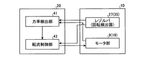
- FIG. 2 is a block diagram showing a configuration for controlling the rotational angle position of the direct drive motor according to the present embodiment.
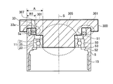
- FIG. 3 is a diagram illustrating a method for fixing the bearing to the rotor flange of the direct drive motor according to the present embodiment.
- FIG. 4 is a diagram illustrating an example of the shape of the jig according to the present embodiment.
- FIG. 5 is a diagram illustrating an example of a manufacturing procedure of the direct drive motor according to the present embodiment.
- FIG. 6 is a diagram showing a first step in the method of manufacturing a direct drive motor according to the present embodiment.
- FIG. 7 is a diagram showing a second step in the method of manufacturing the direct drive motor according to the present embodiment.
- FIG. 8 is a diagram showing a third step in the method for manufacturing the direct drive motor according to the present embodiment.
- FIG. 9 is a diagram showing a fourth step in the method for manufacturing the direct drive motor according to the present embodiment.
- FIG. 10 is a diagram showing a fifth step in the method for manufacturing the direct drive motor according to the present embodiment.
- FIG. 11 is a schematic configuration diagram of an inspection apparatus using the direct drive motor according to the present embodiment.
- FIG. 12 is a schematic configuration diagram of a machine tool using the direct drive motor according to the present embodiment.
- FIG. 1 is a cross-sectional view showing a configuration of a direct drive motor 10 according to the present embodiment.
- a direct drive motor (hereinafter referred to as a DD motor) 10 directly transmits a rotational force to a rotating body without a reduction mechanism (for example, a reduction gear, a transmission belt, etc.), and rotates the rotating body in a predetermined direction. be able to.
- a reduction mechanism for example, a reduction gear, a transmission belt, etc.
- the DD motor 10 of this embodiment is configured as a so-called outer rotor type.
- the DD motor 10 includes an annular housing inner (first housing) 3 fixed to the base 1 and an annular rotor flange (second housing) 5 disposed outside the housing inner 3.
- a motor portion 9 that is incorporated between the housing inner 3 and the rotor flange 5 and rotates the rotor flange 5 with respect to the housing inner 3, and the rotor flange 5 is rotatably supported by the housing inner 3.
- Bearing 11 to be provided.
- the housing inner 3 and the rotor flange 5 are each formed in a substantially cylindrical shape having a different diameter, and are arranged concentrically with the rotation axis S.
- the rotor flange 5 has an integral structure without a break in the axial direction of the rotation shaft S (vertical direction in FIG. 1). That is, the rotor flange 5 is configured in a substantially cylindrical shape that extends continuously from the lower end to the upper end in the axial direction of the rotation axis S, and various workpieces (not shown) are attached to the upper end. It has become. By rotating the rotor flange 5 by the motor unit 9, various workpieces can be rotated in a predetermined direction.
- the rotor flange 5 functions as an output shaft because it rotates around the rotation axis S by the operation of the motor unit 9.
- the housing inner 3 is formed in a substantially cylindrical shape that extends continuously from the lower end to the bearing 11 in the axial direction of the rotary shaft S.
- the bearing 11 is provided with an inner ring presser (fixed ring presser member) 29. And sandwiched between.
- the housing inner 3 and the rotor flange 5 are made of a magnetic material, and the inner ring presser 29 is made of a nonmagnetic material. The reason will be described later.
- the motor unit 9 is disposed in the lower part of the housing 7 (near the base 1).
- the motor unit 9 includes a stator (stator) 13 fixed to the outer peripheral surface of the housing inner 3, and a rotor (rotor) 15 fixed to the inner surface of the rotor flange 5 and disposed to face the stator 13.
- the stator 13 includes a plurality of motor cores 17 arranged concentrically at predetermined intervals (for example, at equal intervals) along the circumferential direction (rotation direction of the rotor flange 5), and multiple wires are wound around each motor core 17.
- a rotated stator coil 19 is fixed.
- the stator 13 is connected to wiring for supplying electric power from the control unit 20 (FIG.
- the rotor 15 is composed of a plurality of permanent magnets arranged concentrically at a predetermined interval (for example, at equal intervals) along the circumferential direction (rotation direction of the rotor flange 5).
- a rotational force is applied to the rotor flange 5 according to Fleming's left-hand rule, and the rotor flange 5 rotates in a predetermined direction.
- the rotor flange 5 is fitted in an inlay hole 200a provided in a rotated body 200 such as a conveying device, an inspection device, and a machine tool, and the rotated body 200 is moved. Rotate.
- a rotated body 200 such as a conveying device, an inspection device, and a machine tool
- the end portion in the axial direction of the rotor flange 5 on the side where the rotated body 200 is attached is defined as the output shaft side end portion.
- the bearing 11 is disposed at a position farther from the base 1 in the axial direction than the motor unit 9.
- the bearing 11 includes an inner ring (fixed ring) 21 and an outer ring (rotating ring) 23 that are opposed to each other so as to be relatively rotatable, and a plurality of rolling elements 25 that are provided between the inner ring 21 and the outer ring 23 so as to be able to roll.
- one bearing 11 is capable of applying both an axial load and a moment load.
- a four-point contact ball bearing, a three-point contact ball bearing, a deep groove ball bearing, or a cross roller bearing Etc. can be adopted.
- a general inner ring or outer ring does not have a split structure, and that an inner and outer ring have an integral structure.
- the inner ring 21 is sandwiched between the housing inner 3 and the inner ring presser 29, and the outer ring 23 is fixed to the inner peripheral surface of the rotor flange 5.
- the support structure of the bearing 11 will be described later.
- the DD motor 10 detects the rotational state (for example, rotational speed, rotational direction, rotational angle, etc.) of the motor unit 9 above the bearing 11 (that is, a position farther from the base 1 in the axial direction than the bearing 11).
- a resolver (rotation detector) 27 is provided.
- the resolver 27 is isolated and protected from the outside by a disk-like cover 31 provided on the upper part of the inner ring presser 29 connected to the housing inner 3.
- the DD motor 10 has a configuration in which the motor unit 9, the bearing 11, and the resolver 27 are arranged in a row in the housing 7 so as to be aligned in the axial direction of the rotation axis S (the vertical direction in FIG. 1).
- the installation area (what is called a footprint) of the housing 7 can be reduced.
- a DD motor having a reduced axial height as well as a housing installation area.
- the resolver 27 is an incremental resolver that detects the relative displacement of the rotor 15 with respect to the stator 13.
- the resolver 27 is disposed to face the inner side of the annular resolver rotor 33 and the resolver rotor 33, has an annular shape with the rotation axis S as the center, and detects a change in reluctance with the resolver rotor 33.
- a resolver stator 35 is adopted by adopting a configuration in which only a single resolver 27 is arranged in the housing 7, the DD motor 10 has a configuration in which two types of resolvers, an absolute resolver and an incremental resolver, are arranged in tandem in the axial direction. The axial height dimension can be reduced.
- the resolver rotor 33 is directly attached to and integrated with the resolver rotor fixing portion 5a formed on the inner peripheral surface of the rotor flange 5 by bolts 33a without any other member.
- the resolver stator 35 is directly attached and integrated with a resolver stator fixing portion 29a formed on the outer peripheral surface of the inner ring retainer 29 by bolts 35a without any other member.
- the reluctance changes depending on the position of the resolver rotor 33.
- the fundamental wave component of the reluctance change per rotation of the rotor flange 5 becomes one cycle.
- the resolver 27 outputs a resolver signal (incremental information) that changes according to the rotational angle position of the rotor flange 5.
- FIG. 2 is a block diagram showing a configuration for controlling the rotational angle position of the DD motor 10 according to the present embodiment.
- a control unit 20 that controls the operation of the DD motor 10 is connected to the DD motor 10.
- the control unit 20 includes a power factor detection unit 41 that detects a position where the power factor becomes 0 when the power to the motor unit 9 is turned on, and a position where the power factor becomes 0 and a resolver signal.
- a commutation control unit 43 for controlling the commutation of.
- the power factor detection unit 41 detects the position of the resolver rotor 33 at which the power factor becomes 0 when the power to the motor unit 9 (stator coil 19) is turned on, and this detected position is used as the reference position. Set as. Then, this reference position is output to the commutation control unit 43.
- the commutation control unit 43 acquires a resolver signal detected by the resolver 27, and controls the commutation timing of the motor current flowing through the motor unit 9 based on the change in the resolver signal and the reference position. This eliminates the need for an absolute resolver when detecting the commutation timing of the motor current, and therefore there is no need to mount two types of rotation detectors, an absolute resolver and an incremental resolver. Therefore, it can be set as a single resolver structure and the height of the DD motor 10 in the axial direction can be suppressed.
- An outer ring fixing portion 50 having a width corresponding to the axial height of the bearing 11 is formed on the inner peripheral surface of the rotor flange 5 over the entire circumference. Over the circumference, a flange portion 51 is formed which is smaller in diameter than the outer diameter of the outer ring (rotating ring) 23 of the bearing 11 and protrudes inward. Further, a groove 52 having a diameter larger than the outer diameter of the outer ring (rotating wheel) 23 of the bearing 11 is formed on the motor part 9 side of the outer ring fixing part 50.
- the flange portion 51 extends toward the one end surface in the axial direction of the outer ring (rotating wheel) 23 (end surface on the resolver 27 side) 23a.
- the flange portion 51 has an inner peripheral surface 51 b of the flange portion 51 positioned outside the inner peripheral surface of the outer ring (rotating wheel) 23 and positioned inside the chamfered portion of the outer ring (rotating wheel) 23. It is preferable to form as follows. According to this, the outer ring (rotating ring) 23 of the bearing 11 can be reliably supported by the flange 51.
- the groove 52 is provided with an outer ring presser (rotating wheel presser member) 53 having a spring force to expand in the outer diameter direction.
- the outer ring presser 53 is the other end surface in the axial direction of the outer ring (rotating wheel) 23. (Motor part 9 side end surface) It extends to the 23b side.
- the outer diameter of the groove 52 is slightly larger than the outermost diameter of the outer ring (rotating ring) 23 of the bearing 11 so that it does not come off even if the allowable load of the bearing 11 itself is applied to the outer ring presser 53.
- the outer ring presser 53 may be, for example, a C-type retaining ring or a spring ring.
- the gap between the outer ring (rotating ring) 23 of the bearing 11 and the outer ring fixing portion 50 formed on the rotor flange 5 is filled with a filler (for example, a molding agent or an adhesive), and the filler is solidified. By doing so, the bearing 11 and the rotor flange 5 are fixed.
- a filler for example, a molding agent or an adhesive
- the outer ring (rotating ring) 23 of the bearing 11 is clamped in the axial direction by the flanges 51 and the outer ring presser 53 provided on the upper and lower sides (both ends) of the outer ring fixing portion 50 in the axial direction.
- the filler filled in the gap between the fixed portion 50 is solidified and fixed.
- the support structure of the inner ring (fixed ring) 21 of the bearing 11 will be described.
- the inner ring (fixed ring) 21 of the bearing 11 is clamped by the housing inner 3 and the inner ring presser 29 and fastened by a plurality of bolts 35b.
- the bolt 35 b for inserting and fixing the housing inner 3 and the inner ring retainer 29 is a different part from the bolt 35 a for fixing the resolver stator 35 to the inner ring retainer 29.
- the outer diameter of the inner ring retainer 29 is larger than the inner diameter of the inner ring (fixed ring) 21 of the bearing 11.
- the outer edge portion of the inner ring retainer 29 extends to the axial one end face (resolver 27 side end face) 21 a side of the inner ring (fixed ring) 21.
- the inner ring retainer 29 is formed such that the outer edge portion of the inner ring retainer 29 is located inside the outer peripheral surface of the inner ring (fixed ring) 21 and located outside the chamfered portion of the inner ring (fixed ring) 21. It is preferable to do. According to this, the inner ring (fixed ring) 21 of the bearing 11 can be reliably supported by the inner ring presser 29.
- an inner ring fixing portion 60 having a width corresponding to the axial height of the bearing 11 from the upper end portion is formed on the outer peripheral surface of the housing inner 3 over the entire circumference, and the motor portion 9 of the inner ring fixing portion 60 is formed.
- a flange 61 is formed over the entire circumference, which is larger than the inner diameter of the inner ring (fixed ring) 21 of the bearing 11 and protrudes outward.
- the flange portion 61 extends toward the other end surface in the axial direction of the inner ring (fixed ring) 21 (end surface on the motor unit 9 side) 21b.
- the flange portion 61 has an outer peripheral surface 61 b of the flange portion 61 positioned on the inner side of the outer peripheral surface of the inner ring (fixed ring) 21 and positioned on the outer side of the chamfered portion of the inner ring (fixed ring) 21.
- the gap between the inner ring (fixed ring) 21 of the bearing 11 and the inner ring fixing portion 60 formed in the housing inner 3 is filled with a filler (for example, a molding agent or an adhesive), and the filler is solidified. By doing so, the bearing 11 and the housing inner 3 are fixed.
- a filler for example, a molding agent or an adhesive
- the inner ring (fixed ring) 21 of the bearing 11 is clamped in the axial direction by the inner ring retainer 29 and the flange 61 provided at the lower end in the axial direction of the inner ring fixing part 60, and the bearing 11 and the inner ring fixing part 60.
- the filler filled in the gap between the two is solidified and fixed.
- the DD motor 10 has a bearing 11 for rotating the rotor flange 5 as the output shaft with high rotational accuracy with respect to the non-rotating components such as the housing inner 3 and the inner ring presser 29. It is necessary to increase the accuracy of the radial width of the structure constituted by the rotor flange 5. Further, in order to detect the rotation of the rotor flange 5 with high accuracy with respect to the housing inner 3 and the resolver stator 35, it is necessary to increase the accuracy of the radial width of the resolver rotor 33 attached to the rotor flange 5.
- FIG. 3 is a diagram illustrating a method for fixing the bearing 11 to the rotor flange 5 of the DD motor 10 according to the present embodiment.
- the components constituting the DD motor 10 such as the bearing 11, the rotor flange 5, the housing inner 3, the inner ring presser 29, and the like are required to have high dimensional accuracy, but allow dimensional tolerance of each component when the components are combined. This requires a margin. Due to this margin, a gap is generated on the fitting surface between the components when the components are combined. Particularly, a gap (for example, 20 ⁇ m to 200 ⁇ m) is provided between the fitting surface between the bearing 11 and the rotor flange 5, that is, between the outer ring (rotating ring) 23 of the bearing 11 and the outer ring fixing portion 50 formed on the rotor flange 5. ) And the gap varies in the circumferential direction, the rotational accuracy of the DD motor 10 is affected.
- a gap for example, 20 ⁇ m to 200 ⁇ m
- a jig 300 is used between the outer peripheral surface of the output shaft side end of the rotor flange 5 and the inner peripheral surface of the inner ring (fixed ring) 21 of the bearing 11.
- the radial width W1 between the outer peripheral surface of the output shaft side end of the rotor flange 5 and the inner peripheral surface of the resolver rotor 33 are defined.
- the outer ring (rotating wheel) 23 of the bearing 11 is fitted into the outer ring fixing portion 50 formed on the rotor flange 5, and the outer ring fixing portion 50 formed on the outer ring (rotating wheel) 23 of the bearing 11 and the rotor flange 5.
- a filler for example, a molding agent or an adhesive
- an outer ring presser 53 is attached, and the outer ring (rotating ring) 23 of the bearing 11 is pivoted between the outer ring presser 53 and the flange 51 of the rotor flange 5. Hold in the direction.
- the resolver rotor 33 is temporarily fixed to the resolver rotor fixing
- a radial width W1 between the outer peripheral surface of the shaft side end and the inner peripheral surface of the resolver rotor 33 is defined, and a gap between the outer ring 23 of the bearing 11 and the outer ring fixing portion 50 formed on the rotor flange 5 is filled. While fixing until the filler is solidified, the resolver rotor 33 is fixed with bolts 33a.
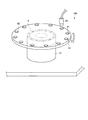
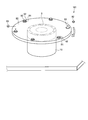
- FIG. 4 is a diagram illustrating an example of the shape of the jig 300 according to the present embodiment.
- the jig 300 includes an annular groove 301 into which the rotor flange 5 is fitted.
- the groove portion 301 has an outer peripheral side wall surface 302 having a radius R1 centered on the rotation axis S and an inner peripheral side wall surface 304 having a radius R2 smaller than the radius R1, and the outer peripheral side wall surface 302 is on the output shaft side of the rotor flange 5.
- the bottom 303 is in contact with the outer peripheral surface of the end, and the bottom 303 is in contact with the axial end surface of the output shaft side end of the rotor flange 5.
- the radial distance between the outer peripheral side wall surface 302 and the inner peripheral side wall surface 304 of the groove portion 301, that is, the radial width W ⁇ b> 1 of the groove portion 301 is the radial width W ⁇ b> 2 of the output shaft side end of the rotor flange 5. (W1> W2).
- the jig 300 is configured such that a columnar convex portion 305 into which the inner ring (fixed ring) 21 of the bearing 11 is fitted projects toward the motor unit 9 side.
- the convex portion 305 has an outer peripheral wall surface 306 with a radius R3 centered on the rotation axis S, and the height H1 from the bottom 303 of the groove 301 to the output shaft side end is the output shaft side end of the rotor flange 5.
- the height H2 from the axial end surface to the output shaft side end surface of the bearing 11 is greater (H1> H2), and the outer peripheral wall surface 306 is in contact with the inner peripheral surface of the inner ring (fixed ring) 21 of the bearing 11. It is configured as follows.
- the height H1 of the convex portion 305 is configured to be not less than the height H3 from the axial end surface of the output shaft side end portion of the rotor flange 5 to the end surface of the bearing 11 on the motor portion 9 side. Is more preferable (H1 ⁇ H3).
- the height H4 of the inner peripheral side wall surface 304 of the groove portion 301 of the jig 300 is not less than the height H5 from the axial end surface of the output shaft side end portion of the rotor flange 5 to the resolver rotor fixing portion 5a, and the rotor flange. 5 is configured such that the height from the axial end surface of the output shaft side end portion to the output shaft side end surface of the bearing 11 is less than H2 (H5 ⁇ H4 ⁇ H2), and the inner peripheral side wall surface 304 of the resolver rotor 33 is It is comprised so that an inner peripheral surface may be contact
- the jig 300 does not have to have a shape that extends around the rotation axis S of the DD motor 10 as shown in FIGS. 3 and 4.
- the jig 300 has at least three directions extending radially from the rotation axis S (
- the radial width A between the outer peripheral surface of the output shaft side end of the rotor flange 5 and the inner peripheral surface of the inner ring (fixed ring) 21 of the bearing 11 in three directions shifted by 120 ° in the circumferential direction and
- the shape may be such that the radial width W1 between the outer peripheral surface of the output shaft side end of the rotor flange 5 and the inner peripheral surface of the resolver rotor 33 can be defined.
- the jig 300 may have a hollow structure, and the radial width A between the outer peripheral surface of the output shaft side end portion of the rotor flange 5 and the inner peripheral surface of the inner ring (fixed ring) 21 of the bearing 11 and Any material can be used as long as it can define the radial width W1 between the outer peripheral surface of the output shaft side end of the rotor flange 5 and the inner peripheral surface of the resolver rotor 33.
- the housing inner 3 and the inner ring presser 29 are defined as structures that constitute the fixing part of the DD motor 10, and the rotor flange 5 is a structure that constitutes the rotating part of the DD motor 10. Define as a body.
- the structure constituting the rotating part is composed of a lower rotor flange member and an upper outer ring pressing member, and the outer ring (rotating wheel) of the bearing is sandwiched between the outer ring pressing member and the rotor flange member
- the outer ring (rotating ring) of the bearing is clamped between the outer ring pressing member and the rotor flange member, and the bolt is fastened to fix the bearing.
- the components constituting the DD motor are fixed. The number of points increases, and the margin for allowing the dimensional tolerance of each component may reduce the dimensional accuracy when the DD motor is assembled.
- the rotor flange 5 that is a structure constituting the rotating part of the DD motor 10 has an integral structure without a break in the axial direction of the rotating shaft S (vertical direction in FIG. 1).
- the axial direction of the rotating shaft S it is configured in a substantially cylindrical shape that is continuous over the entire circumference from the lower end to the upper end. For this reason, it is possible to suppress a decrease in dimensional accuracy when the DD motor 10 is assembled, and the diameter between the output shaft side end of the rotor flange 5 and the inner peripheral surface of the inner ring (fixed ring) 21 of the bearing 11.
- the rotation variation of the gap between the stator (stator) 13 and the rotor (rotor) 15, that is, the motor gap is suppressed, so that the cogging torque can be suppressed.
- the number of parts for configuring the DD motor 10 is reduced, the cost and manufacturing cost of the DD motor 10 can be reduced.
- the accuracy of rotation detection of the DD motor 10 can be improved. it can.
- the height dimension of the axial direction of DD motor 10 can be reduced, and in connection with it.
- the height dimension of the rotor flange 5 in the axial direction can be reduced. Thereby, the usage-amount of the material of the rotor flange 5 can be reduced, and it can contribute to the cost reduction of the DD motor 10.
- FIG. 5 is a diagram illustrating an example of a manufacturing procedure of the DD motor 10 according to the present embodiment.
- FIG. 6 is a diagram showing a first step in the method for manufacturing the DD motor 10 according to the present embodiment.
- FIG. 7 is a diagram showing a second step in the method for manufacturing the DD motor 10 according to the present embodiment.
- FIG. 8 is a diagram showing a third step in the method for manufacturing the DD motor 10 according to the present embodiment.
- FIG. 9 is a diagram showing a fourth step in the method for manufacturing the DD motor 10 according to the present embodiment.
- FIG. 10 is a diagram showing a fifth step in the method for manufacturing the DD motor 10 according to the present embodiment.
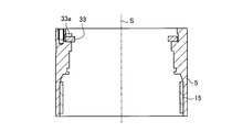
- a plurality of permanent magnets constituting the rotor 15 are stuck and fixed at predetermined positions in the axial direction of the inner peripheral surface of the rotor flange 5.
- the permanent magnets are concentrically arranged and fixed at predetermined intervals (for example, equal intervals) in the circumferential direction (rotation direction of the rotor flange 5) (step ST101 in FIG. 5).
- the fixing means for the permanent magnet to the rotor flange 5 may be a known fixing means such as an adhesive, and the present invention is not limited to the fixing means.
- an example is shown in which the permanent magnet is attached to the inner peripheral surface of the rotor flange 5 and fixed.
- the permanent magnet is embedded in the rotor flange 5 and arranged concentrically in the circumferential direction. Also good. Further, the resolver rotor 33 is temporarily fixed to the resolver rotor fixing portion 5a formed on the inner peripheral surface of the rotor flange 5 by a bolt 33a so that the position adjustment is possible.
- the end portion in the output shaft direction of the rotor flange 5 to which the rotor 15 is fixed in the first step is fitted in the groove portion 301 of the jig 300 in the axial direction, and temporarily fixed to the rotor flange 5.
- the inner peripheral surface of the resolved resolver rotor 33 is fitted into the inner peripheral side wall surface 304 of the groove portion 301 of the jig 300, and the bearing 11 is fitted into the convex portion 305 of the jig 300 in the axial direction.
- the gap formed between the outer ring (rotating ring) 23 of the bearing 11 and the outer ring fixing portion 50 of the rotor flange 5 is filled with a filler (for example, a molding agent or an adhesive), and the outer ring presser 53 is connected to the rotor flange. 5, the outer ring (rotating ring) 23 of the bearing 11 is clamped in the axial direction by the outer ring presser 53 and the flange 51 of the rotor flange 5 (step ST102 in FIG. 5). Then, the bolt 33a of the resolver rotor 33 is finally tightened and fixed.
- the jig 300 is provided with a plurality of through holes 307 through which a tool for turning the bolt 33a passes.
- an adhesive may be applied to the outer ring fixing portion 50 of the rotor flange 5 so that the rotor flange 5 and the bearing 11 are combined.
- the adhesive applied in advance at any of the edges is scraped, and the gap between the rotor flange 5 and the bearing 11 is sufficiently adhesive. It is possible that it will not be satisfied. For this reason, in a state where the rotor flange 5 and the bearing 11 are incorporated in the jig 300, a filler is formed in a gap formed between the outer ring (rotating ring) 23 of the bearing 11 and the outer ring fixing portion 50 of the rotor flange 5. Is preferably filled.
- the jig 300 is fitted with the resolver rotor 33 temporarily fixed to the rotor flange.
- the jig is fixed.
- the resolver rotor 33 may be fixed to the rotor flange 5 after the tool 300 is fitted into the housing rotor 5.
- the through hole 307 of the jig 300 has a size that allows the bolt 33a to pass sufficiently.
- the bearing 300 and the rotor flange 5 are fixed, and then the jig 300 is removed.
- the timing for removing the jig 300 may be any time as long as it is before the fourth step described later.
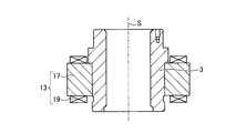
- a plurality of motor cores 17 constituting the stator 13 are stuck and fixed at predetermined positions in the axial direction on the outer peripheral surface of the housing inner 3.
- the motor cores 17 are arranged and fixed concentrically at predetermined intervals (for example, at equal intervals) in the circumferential direction (rotation direction of the rotor flange 5) (step ST103 in FIG. 5).
- Each motor core 17 is fixed with a stator coil 19 formed by winding multiple wires.
- the fixing means for the motor core 17 to the housing inner 3 and the fixing means for the stator coil 19 to the motor core 17 may be known fixing means such as an adhesive, for example, and the present invention is not limited by these fixing means. Absent.
- the inner ring fixing portion 60 formed on the outer peripheral surface of the housing inner 3 is inserted into the inner ring (fixed ring) 21 of the bearing 11 (step ST104 in FIG. 5). Then, a filler (for example, a molding agent or an adhesive) is filled in a gap between the inner ring (fixed ring) 21 of the bearing 11 and the inner ring fixing portion 60 formed in the housing inner 3.
- a filler for example, a molding agent or an adhesive
- the inner ring (fixed ring) 21 of the bearing 11 is sandwiched between the housing inner 3 and the inner ring retainer 29 and fastened by a plurality of bolts 35b, whereby the inner ring of the bearing 11 is secured.
- the (fixed ring) 21 is fixed and supported in the axial direction (step ST105 in FIG. 5). Thereafter, the filler filled in the gap between the bearing 11 and the housing inner 3 is solidified, whereby the bearing 11 and the housing inner 3 are fixed.
- the filler is filled in the gap between the bearing 11 and the housing inner 3.
- the fixing means for the bearing 11 and the housing inner 3 is not limited to this, and other known fixing means may be used. It may be used. Further, when a sufficient fixing strength can be obtained by clamping the inner ring (fixed ring) 21 of the bearing 11 between the housing inner 3 and the inner ring presser 29 and fastening with a plurality of bolts 35b, a filler or other The fixing means may not be used together.
- the resolver stator 35 is integrally attached to the resolver stator fixing portion 29a formed on the outer peripheral surface of the inner ring presser 29 by the bolt 35a, and the cover 31, the base 1 and the like are attached, and the DD motor 10 is completed (FIG. 1).
- the attachment timing of the resolver stator 35 is not limited to after the fifth step.
- the resolver stator 35 may be attached to the inner ring retainer 29 in advance before the fifth step.
- the present invention is not limited by the attaching procedure of the resolver stator 35.
- DD motor rotor flange, housing inner, bearing, inner ring presser, etc.
- the resolver 27 detects the rotational angle position of the rotor flange 5 by performing magnetic sensing as described above, the rotational angle of the rotor flange 5 is caused by the magnetic wraparound from the motor unit 9. The position detection accuracy may be adversely affected.
- the structure constituting the fixed portion is constituted by one housing inner member
- the influence of the magnetic wraparound from the motor portion is avoided via the housing inner member constituted by the magnetic material. Therefore, it is necessary to attach the resolver stator to the housing inner member via an attachment member made of another nonmagnetic material.
- the housing inner 3 and the inner ring presser 29 made of a nonmagnetic material that sandwiches the bearing 11 together with the housing inner 3 constitute a fixing portion, and further, the housing inner 3 and the inner ring
- the bolt 35 b for inserting and fixing the presser 29 is a different part from the bolt 35 a for fixing the resolver stator 35 to the inner ring presser 29. That is, the housing inner 3 made of a magnetic material and the resolver stator 35 are not electrically connected.
- FIG. 11 is a schematic configuration diagram of the inspection apparatus 100 using the DD motor 10 according to the present embodiment.
- a table 80 on a disk is connected to the upper end of the rotor flange 5 of the DD motor 10, and the table 80 is rotated by the operation of the rotor flange 5.
- Inspection objects (conveyed objects) 81 are arranged at equal intervals on the edge of the table 80.
- the inspection object 81 is rotated and conveyed together with the table 80 by the operation of the DD motor 10, and thus includes the DD motor 10 and the table 80 to constitute a conveying device.
- a camera (inspection unit) 82 for individually observing the inspection object 81 rotated (conveyed) together with the table 80 is disposed above the edge of the table 80.
- the inspection object 81 can be inspected based on the photographed image. According to this configuration, it is possible to improve the positional accuracy when moving the inspection object 81 below the camera 82 and to reduce the size of the inspection apparatus 100.
- FIG. 12 is a schematic configuration diagram of a machine tool 101 using the DD motor 10 according to the present embodiment.
- a table 80 on a disk is connected to the upper end of the rotor flange 5 of the DD motor 10, and the table 80 is rotated by the operation of the rotor flange 5.
- a processing object (object) 91 is arranged on the edge of the table 80 at equal intervals.
- a loading robot (processing unit) that performs processing for stacking new parts 92 and 93 on the processing target 91 is disposed at the edge of the table 80, and the processing target is synchronized with the rotation of the table 80. 91 can be processed. According to this configuration, it is possible to improve the position accuracy when moving the workpiece 91 to the position of the loading robot and to reduce the size of the machine tool 101.
- the DD motor 10 includes the motor unit 9 including the stator 13 and the rotor 15 that can rotate with respect to the stator 13, and the housing inner ( The first housing 3, the rotor flange (second housing) 5 that is disposed outside the housing inner (first housing) 3 and to which the rotor 15 is fixed, and the rotor flange with respect to the housing inner (first housing) 3 A bearing 11 that rotatably supports the (second housing) 5, and an inner ring presser (fixed ring presser member) 29 that holds the inner ring (fixed ring) 21 of the bearing 11 together with the housing inner (first housing) 3 in the axial direction. And a resolver 27 for detecting the rotation state of the motor unit 9.
- the outer ring (rotating ring) 23 of the bearing 11 is fitted into the outer ring fixing portion 50 formed in the rotor flange (second housing) 5, and the outer ring (rotating ring) 23 of the bearing 11 and the rotor are fitted.
- a filler for example, a molding agent and an adhesive
- the resolver 27 includes the resolver rotor 33 and the resolver stator 35 disposed to face the resolver rotor 33, and the output shaft side end portion of the rotor flange 5 using the jig 300.
- a radial width W1 between the outer peripheral surface of the resolver rotor 33 and the inner peripheral surface of the resolver rotor 33 is defined, the resolver rotor 33 is directly fixed to the rotor flange (second housing) 5, and the resolver stator 35 is fixed to the inner ring presser (fixed ring presser). Member) 29 and directly fixed to the member.
- the inner ring presser (fixed ring presser member) 29 is made of a nonmagnetic material, so that the rotor flange (second housing) 5 is caused by the magnetic wraparound from the motor unit 9 to the resolver stator 35.
- the influence on the detection accuracy of the rotation angle position can be suppressed, and the rotation state of the motor unit 9 can be detected with higher accuracy.
- the resolver 27 is an incremental type single resolver that detects the relative displacement of the rotor 15 with respect to the stator 13. For this reason, the height dimension of the housing 7 in the axial direction can be reduced, and the DD motor 10 can be downsized in the axial direction.
- the power factor detection unit 41 that detects a position where the power factor becomes 0 when the power to the motor unit 9 is turned on, and the resolver signal output from the resolver 27 and the position where the power factor becomes 0.
- a commutation control unit 43 that controls the commutation of the motor unit 9.
- the motor unit 9, the bearing 11, and the resolver 27 are arranged side by side in the axial direction of the bearing 11. Thereby, the enlargement to the radial direction centering on the rotating shaft S is suppressed, and the installation area (what is called a footprint) of DD motor 10 can be reduced.
- the rotor flange (second housing) 5 includes the flange portion 51 that extends to the axial one end face 23 a side of the outer ring (rotating ring) 23 of the bearing 11, and the outer ring (rotating ring) 23.
- the rotor flange (second housing) 5 is formed in a substantially cylindrical shape and has an integral structure without any break in the axial direction. With this structure, it is possible to support the bearing 11 while suppressing the rotor flange (second housing) 5 from being enlarged in the axial direction, and the DD motor 10 can be reduced in size.
- embodiment is not limited by the content mentioned above.
- a configuration including a single bearing 11 is described.
Landscapes
- Engineering & Computer Science (AREA)
- Power Engineering (AREA)
- Manufacturing & Machinery (AREA)
- Microelectronics & Electronic Packaging (AREA)
- Manufacture Of Motors, Generators (AREA)
- Permanent Magnet Type Synchronous Machine (AREA)
Abstract
Description
その後、軸受11とロータフランジ5との隙間に充填された充填剤が固化することによって、軸受11とロータフランジ5とが固定された後に、治具300が外される。なお、治具300を外すタイミングは、後述する第4工程の前であればいつでも良い。
5 ロータフランジ(第2ハウジング)
7 ハウジング
9 モータ部
10 DDモータ
11 軸受
13 ステータ(固定子)
15 ロータ(回転子)
20 制御ユニット
21 内輪(固定輪)
21a 内輪(固定輪)の軸方向一端面(一方の軸方向端面)
21b 内輪(固定輪)の軸方向他端面(他方の軸方向端面)
23 外輪(回転輪)
23a 外輪(回転輪)の軸方向一端面(一方の軸方向端面)
23b 外輪(回転輪)の軸方向他端面(他方の軸方向端面)
25 転動体
27 レゾルバ(回転検出器)
29 内輪押え(固定輪押え部材)
33 レゾルバロータ
35 レゾルバステータ
41 力率検出部
43 転流制御部
51 鍔部(ロータフランジ)
52 溝部
53 外輪押え(回転輪押え部材)
60 内輪固定部
61 鍔部(ハウジングインナ)
80 テーブル
81 検査対象物(搬送物)
82 カメラ(検査部)
91 加工対象物(対象物)
100 検査装置
101 工作機械
200 被回転体
200a インロー穴(被回転体)
300 治具
301 溝部(治具)
302 外周側壁面(溝部)
303 底部(溝部)
304 内周側壁面(溝部)
305 凸部(治具)
306 外周壁面(凸部)
307 貫通孔
S 回転軸
Claims (11)
- 固定子と該固定子に対して回転可能な回転子とを有するモータ部と、前記固定子が固定される第1ハウジングと、前記第1ハウジングの外側に配置され、前記回転子が固定される第2ハウジングと、前記第1ハウジングに対して前記第2ハウジングを回転自在に支持する軸受と、前記第1ハウジングと共に前記軸受の固定輪を軸方向に挟持する固定輪押え部材と、前記モータ部の回転状態を検出するための回転検出器と、を備えるダイレクトドライブモータの製造方法であって、
前記第2ハウジングの軸方向所定位置に前記回転子を構成する複数個の永久磁石を周方向に所定間隔で同心状に配置し固定する工程と、
前記第2ハウジングに前記軸受の回転輪を嵌め込み、前記軸受の回転輪と前記第2ハウジングとの隙間に充填剤を充填し、前記第2ハウジングの外周面と前記軸受の固定輪の内周面との間の径方向幅が規定された治具で固定する工程と、
前記第1ハウジングの外周面の軸方向所定位置に前記固定子を構成する複数個のモータコアを周方向に所定間隔で同心状に配置し固定する工程と、
前記軸受の固定輪に前記第1ハウジングを挿入する工程と、
前記軸受の固定輪を前記第1ハウジングと前記固定輪押え部材とで挟持し、前記軸受の固定輪を軸方向に固定する工程と、
を有するダイレクトドライブモータの製造方法。 - 前記ダイレクトドライブモータは、前記回転検出器がレゾルバロータと該レゾルバロータに対向して配置されるレゾルバステータとを含み、
前記レゾルバロータを前記第2ハウジングに直接固定する工程と、
前記レゾルバステータを前記固定輪押え部材に直接固定する工程と、
をさらに有する請求項1に記載のダイレクトドライブモータの製造方法。 - 前記第2ハウジングに前記レゾルバロータを嵌め込み、前記第2ハウジングの外周面と前記レゾルバロータの内周面との間の径方向幅が規定された治具で固定する工程をさらに有する請求項2に記載のダイレクトドライブモータの製造方法。
- 固定子と該固定子に対して回転可能な回転子とを有するモータ部と、前記固定子が固定される第1ハウジングと、前記第1ハウジングの外側に配置され、前記回転子が固定される第2ハウジングと、前記第1ハウジングに対して前記第2ハウジングを回転自在に支持する軸受と、前記第1ハウジングと共に前記軸受の固定輪を軸方向に挟持する固定輪押え部材と、前記モータ部の回転状態を検出するための回転検出器と、を備えるダイレクトドライブモータの製造方法で用いられる治具であって、
前記第2ハウジングが嵌め込まれる円環状の溝部と、
前記軸受の固定輪を嵌め込む円柱状の凸部と、
を含み、
前記円環状の溝部は、
前記モータ部の回転軸を中心とする外周側壁面と、
前記外周側壁面よりも半径が大きい内周側壁面と、
を有し、
当該円環状の溝部の径方向幅が前記第2ハウジングの出力軸側端部の径方向幅よりも大きく、前記外周側壁面が前記第2ハウジングの出力軸側端部の外周面に接し、当該円環状の溝部の底部が前記第2ハウジングの出力軸側端部の軸方向端面に接するように構成され、
前記円柱状の凸部は、
前記モータ部の回転軸を中心とする外周壁面を有し、
前記円環状の溝部の底面から当該円柱状の凸部の出力軸側端部までの高さが前記第2ハウジングの出力軸側端部の軸方向端面から前記軸受の出力軸側端面までの高さよりも大きく、前記外周壁面が前記軸受の固定輪の内周面に接するように構成され、
前記円環状の溝部の前記内周側壁面と前記円柱状の凸部の前記外周壁面との間の径方向距離によって、前記第2ハウジングの外周面と前記軸受の固定輪の内周面との間の径方向幅を規定する治具。 - 前記ダイレクトドライブモータは、前記回転検出器がレゾルバロータと該レゾルバロータに対向して配置されるレゾルバステータとを含み、
前記円環状の溝部の前記内周側壁面と前記外周側壁面との間の径方向距離によって、前記第2ハウジングの外周面と前記レゾルバロータの内周面との間の径方向幅を規定する請求項4に記載の治具。 - 前記ダイレクトドライブモータは、前記固定輪押え部材が非磁性材料で構成されている請求項1に記載のダイレクトドライブモータの製造方法。
- 前記ダイレクトドライブモータは、前記回転検出器が前記固定子に対する前記回転子の相対変位を検出するインクリメンタル方式の単一のレゾルバである請求項1に記載のダイレクトドライブモータの製造方法。
- 前記ダイレクトドライブモータは、
前記モータ部への電源投入時に力率が0となる位置を検出する力率検出部と、
前記力率が0となる位置と前記レゾルバから出力されるインクリメンタル情報とにより、該モータ部の転流を制御する転流制御部と、
を備える請求項7に記載のダイレクトドライブモータの製造方法。 - 前記ダイレクトドライブモータは、前記モータ部、前記軸受、及び、前記回転検出器が前記軸受の軸方向に並んで配置される請求項1に記載のダイレクトドライブモータの製造方法。
- 前記ダイレクトドライブモータは、前記第2ハウジングが前記軸受の回転輪の一方の軸方向端面側に延在する鍔部と、該回転輪の他方の軸方向端面側に配置される回転輪押え部材と、を備えた請求項1に記載のダイレクトドライブモータの製造方法。
- 前記ダイレクトドライブモータは、前記第2ハウジングが略円筒形状に形成され、かつ、前記軸方向に切れ目のない一体構造である請求項1に記載のダイレクトドライブモータの製造方法。
Priority Applications (3)
| Application Number | Priority Date | Filing Date | Title |
|---|---|---|---|
| CN201580040205.5A CN106537737B (zh) | 2014-07-31 | 2015-07-22 | 直接驱动电动机的制造方法和夹具 |
| JP2016538293A JP6540704B2 (ja) | 2014-07-31 | 2015-07-22 | ダイレクトドライブモータの製造方法、及び治具 |
| KR1020177001982A KR102378491B1 (ko) | 2014-07-31 | 2015-07-22 | 다이렉트 드라이브 모터의 제조 방법, 및 지그 |
Applications Claiming Priority (4)
| Application Number | Priority Date | Filing Date | Title |
|---|---|---|---|
| JP2014-156348 | 2014-07-31 | ||
| JP2014156348 | 2014-07-31 | ||
| JP2014-177587 | 2014-09-01 | ||
| JP2014177587 | 2014-09-01 |
Publications (1)
| Publication Number | Publication Date |
|---|---|
| WO2016017504A1 true WO2016017504A1 (ja) | 2016-02-04 |
Family
ID=55217405
Family Applications (1)
| Application Number | Title | Priority Date | Filing Date |
|---|---|---|---|
| PCT/JP2015/070847 Ceased WO2016017504A1 (ja) | 2014-07-31 | 2015-07-22 | ダイレクトドライブモータの製造方法、及び治具 |
Country Status (5)
| Country | Link |
|---|---|
| JP (1) | JP6540704B2 (ja) |
| KR (1) | KR102378491B1 (ja) |
| CN (1) | CN106537737B (ja) |
| TW (1) | TWI586082B (ja) |
| WO (1) | WO2016017504A1 (ja) |
Cited By (4)
| Publication number | Priority date | Publication date | Assignee | Title |
|---|---|---|---|---|
| CN108988600A (zh) * | 2018-09-28 | 2018-12-11 | 成都微精电机股份公司 | 一种适用于高精度力矩电机的紧凑结构 |
| JP2018207758A (ja) * | 2017-06-09 | 2018-12-27 | 日本精工株式会社 | ダイレクトドライブモータ及び処理装置 |
| CN110109014A (zh) * | 2019-05-31 | 2019-08-09 | 苏州绿控传动科技股份有限公司 | 一种旋转变压器综合测试实验台 |
| JP2020043667A (ja) * | 2018-09-10 | 2020-03-19 | 住友重機械工業株式会社 | ギヤモータ |
Families Citing this family (3)
| Publication number | Priority date | Publication date | Assignee | Title |
|---|---|---|---|---|
| CN106849519B (zh) * | 2017-03-30 | 2024-04-09 | 湘潭电机股份有限公司 | 一种旋转变压器的安装结构 |
| US11245318B1 (en) * | 2020-07-29 | 2022-02-08 | Schaeffler Technologies AG & Co. KG | Resolver clamping plate for electric motor |
| KR102816669B1 (ko) * | 2023-05-12 | 2025-06-05 | 하이젠알앤엠 주식회사 | 모터 장치 |
Citations (4)
| Publication number | Priority date | Publication date | Assignee | Title |
|---|---|---|---|---|
| JPH02254601A (ja) * | 1989-03-27 | 1990-10-15 | Sharp Corp | ロータリトランスの取付方法 |
| JP2002315278A (ja) * | 2001-04-17 | 2002-10-25 | Matsushita Electric Ind Co Ltd | ロータ構体の組立方法 |
| JP2008180362A (ja) * | 2006-12-29 | 2008-08-07 | Nsk Ltd | 充填剤による固定構造を有する転がり軸受装置 |
| JP2012178926A (ja) * | 2011-02-25 | 2012-09-13 | Nsk Ltd | モータロータ及びモータハウジング一体モータ構造 |
Family Cites Families (1)
| Publication number | Priority date | Publication date | Assignee | Title |
|---|---|---|---|---|
| TWI234765B (en) * | 2001-03-29 | 2005-06-21 | Matsushita Electric Industrial Co Ltd | Rotor assembly, information-recording/-reproducing device and method of assembling the rotor assembly |
-
2015
- 2015-07-22 KR KR1020177001982A patent/KR102378491B1/ko active Active
- 2015-07-22 CN CN201580040205.5A patent/CN106537737B/zh active Active
- 2015-07-22 WO PCT/JP2015/070847 patent/WO2016017504A1/ja not_active Ceased
- 2015-07-22 JP JP2016538293A patent/JP6540704B2/ja active Active
- 2015-07-30 TW TW104124747A patent/TWI586082B/zh not_active IP Right Cessation
Patent Citations (4)
| Publication number | Priority date | Publication date | Assignee | Title |
|---|---|---|---|---|
| JPH02254601A (ja) * | 1989-03-27 | 1990-10-15 | Sharp Corp | ロータリトランスの取付方法 |
| JP2002315278A (ja) * | 2001-04-17 | 2002-10-25 | Matsushita Electric Ind Co Ltd | ロータ構体の組立方法 |
| JP2008180362A (ja) * | 2006-12-29 | 2008-08-07 | Nsk Ltd | 充填剤による固定構造を有する転がり軸受装置 |
| JP2012178926A (ja) * | 2011-02-25 | 2012-09-13 | Nsk Ltd | モータロータ及びモータハウジング一体モータ構造 |
Cited By (7)
| Publication number | Priority date | Publication date | Assignee | Title |
|---|---|---|---|---|
| JP2018207758A (ja) * | 2017-06-09 | 2018-12-27 | 日本精工株式会社 | ダイレクトドライブモータ及び処理装置 |
| JP2020043667A (ja) * | 2018-09-10 | 2020-03-19 | 住友重機械工業株式会社 | ギヤモータ |
| JP7252725B2 (ja) | 2018-09-10 | 2023-04-05 | 住友重機械工業株式会社 | ギヤモータ |
| CN108988600A (zh) * | 2018-09-28 | 2018-12-11 | 成都微精电机股份公司 | 一种适用于高精度力矩电机的紧凑结构 |
| CN108988600B (zh) * | 2018-09-28 | 2024-04-02 | 成都微精电机股份公司 | 一种适用于高精度力矩电机的紧凑结构 |
| CN110109014A (zh) * | 2019-05-31 | 2019-08-09 | 苏州绿控传动科技股份有限公司 | 一种旋转变压器综合测试实验台 |
| CN110109014B (zh) * | 2019-05-31 | 2024-04-26 | 苏州绿控传动科技股份有限公司 | 一种旋转变压器综合测试实验台 |
Also Published As
| Publication number | Publication date |
|---|---|
| JPWO2016017504A1 (ja) | 2017-05-18 |
| CN106537737B (zh) | 2019-11-22 |
| KR20170027337A (ko) | 2017-03-09 |
| TW201622317A (zh) | 2016-06-16 |
| TWI586082B (zh) | 2017-06-01 |
| KR102378491B1 (ko) | 2022-03-25 |
| CN106537737A (zh) | 2017-03-22 |
| JP6540704B2 (ja) | 2019-07-10 |
Similar Documents
| Publication | Publication Date | Title |
|---|---|---|
| JP6540704B2 (ja) | ダイレクトドライブモータの製造方法、及び治具 | |
| JP4636432B2 (ja) | 回転駆動装置 | |
| US20190097497A1 (en) | Motor | |
| JP5673206B2 (ja) | ダイレクトドライブモータ、位置決め装置及び機械装置 | |
| KR20190032371A (ko) | 2축 일체형 모터 | |
| JP2020129951A (ja) | 電動機およびその製造方法 | |
| CN106464113A (zh) | 直接驱动电动机、输送装置、检查装置以及机床 | |
| JP6525008B2 (ja) | ダイレクトドライブモータ、搬送装置、検査装置、及び、工作機械 | |
| JP6850304B2 (ja) | 回転位置検出装置 | |
| JP2013099000A (ja) | レゾルバの取付構造 | |
| US20080317398A1 (en) | Magnetic bearing device and machine tool provided with the same | |
| JP2009050055A (ja) | 回転電機のロータ | |
| KR102462298B1 (ko) | 영구 자석의 회전의 수 측정을 위한 센서 어셈블리 | |
| JP5155632B2 (ja) | ブラシレスモータ | |
| JP2013027122A (ja) | レゾルバ及びその製造方法、並びにレゾルバ付き転がり軸受装置 | |
| CN104052198A (zh) | 旋转电机 | |
| JP5971320B2 (ja) | ダイレクトドライブモータ、位置決め装置、機械装置及びハウジング部品 | |
| JP6507964B2 (ja) | ローラ | |
| JP2008215513A (ja) | 電磁石による予圧付与構造を有する転がり軸受装置 | |
| JP4293058B2 (ja) | 回転速度検出装置 | |
| JP6848705B2 (ja) | モータ、モータの製造方法及び処理装置 | |
| JP2007244029A (ja) | モータシャフト及びその製造装置 | |
| JP2008215508A (ja) | 回転センサのユニット取付構造を有する転がり軸受装置および駆動体のユニット取付構造を有する転がり軸受装置 | |
| JP2021083144A (ja) | 回転電機 | |
| JP2007252039A (ja) | ブラシレスモータ |
Legal Events
| Date | Code | Title | Description |
|---|---|---|---|
| 121 | Ep: the epo has been informed by wipo that ep was designated in this application |
Ref document number: 15826465 Country of ref document: EP Kind code of ref document: A1 |
|
| ENP | Entry into the national phase |
Ref document number: 2016538293 Country of ref document: JP Kind code of ref document: A |
|
| ENP | Entry into the national phase |
Ref document number: 20177001982 Country of ref document: KR Kind code of ref document: A |
|
| NENP | Non-entry into the national phase |
Ref country code: DE |
|
| 122 | Ep: pct application non-entry in european phase |
Ref document number: 15826465 Country of ref document: EP Kind code of ref document: A1 |