WO2016017228A1 - プレス成形(press forming)方法 - Google Patents
プレス成形(press forming)方法 Download PDFInfo
- Publication number
- WO2016017228A1 WO2016017228A1 PCT/JP2015/063519 JP2015063519W WO2016017228A1 WO 2016017228 A1 WO2016017228 A1 WO 2016017228A1 JP 2015063519 W JP2015063519 W JP 2015063519W WO 2016017228 A1 WO2016017228 A1 WO 2016017228A1
- Authority
- WO
- WIPO (PCT)
- Prior art keywords
- molding
- flange
- mold
- press
- groove
- Prior art date
- Legal status (The legal status is an assumption and is not a legal conclusion. Google has not performed a legal analysis and makes no representation as to the accuracy of the status listed.)
- Ceased
Links
Images
























Classifications
-
- B—PERFORMING OPERATIONS; TRANSPORTING
- B21—MECHANICAL METAL-WORKING WITHOUT ESSENTIALLY REMOVING MATERIAL; PUNCHING METAL
- B21D—WORKING OR PROCESSING OF SHEET METAL OR METAL TUBES, RODS OR PROFILES WITHOUT ESSENTIALLY REMOVING MATERIAL; PUNCHING METAL
- B21D22/00—Shaping without cutting, by stamping, spinning, or deep-drawing
- B21D22/20—Deep-drawing
- B21D22/26—Deep-drawing for making peculiarly, e.g. irregularly, shaped articles
-
- B—PERFORMING OPERATIONS; TRANSPORTING
- B21—MECHANICAL METAL-WORKING WITHOUT ESSENTIALLY REMOVING MATERIAL; PUNCHING METAL
- B21D—WORKING OR PROCESSING OF SHEET METAL OR METAL TUBES, RODS OR PROFILES WITHOUT ESSENTIALLY REMOVING MATERIAL; PUNCHING METAL
- B21D37/00—Tools as parts of machines covered by this subclass
- B21D37/10—Die sets; Pillar guides
Definitions
- the present invention has a channel-shaped potion, and at least one vertical wall portion of a pair of side wall portions forming the groove-shaped portion, the groove bottom portion in the groove-shaped portion
- the present invention relates to a press molding method of molding a molded product (press forming part) having a flange portion that is curved so as to be convex or concave toward the (channel bottom portion) side.
- press molding In press molding, the shape of the mold is transferred to the blank by pressing the tool of the material (steel sheet) (blank), and the blank is processed. It is a method. In press molding, after a press-molded product is taken out of a mold, a so-called spring back, which is a defect of shape caused by elastic recovery of residual stress in the press-molded product. (Springback) occurs. Due to this, a problem that the shape of the press-formed product is different from the desired shape often occurs.
- Patent Document 1 proposes a method in which a blank is press-molded with a mold having a convex bead in a flange when a hat-shaped section part is formed by a crash. ing. In this method, the blank is locked to the convex bead just before the bottom dead center and tensile deformation is applied to the vertical wall of the blank, which causes the vertical wall curl. The stress difference in the thickness direction is eliminated.
- Patent Document 2 proposes a method in which a blank is press-molded with a mold in which a blank holder provided on the outer periphery of a punch is provided with a depression.
- the blank end enters the recess of the blank holder, and when the press molding proceeds further, the blank end is caught by the inner wall of the recess and restrained. For this reason, the blank does not flow out. Therefore, in this method, in-plane compressive stress can be applied to the vertical wall portion of the blank immediately before the bottom dead center, thereby eliminating the stress difference in the plate thickness direction.
- Patent Document 3 “in the plane perpendicular to the high-strength steel sheet including the horizontal line connecting the intersection of the vertical wall portion and the flange portion and the center of curvature of the curved portion, the horizontal line A first molding step in which the flange portion is bent at the intersection until the angle of the flange portion with respect to ⁇ is ⁇ 1 , and the first molding step until the angle of the flange portion with respect to the horizontal line is ⁇ 2 in the plane.
- Japanese Patent No. 4090028 JP 2010-99700 A Japanese Patent No. 5382281
- Patent Documents 1 and 2 are effective as a countermeasure against only a shape change that occurs in a specific cross section due to springback.
- three-dimensional springback that occurs in the entire part, such as torsion and bending often becomes a problem. Therefore, the prior art described in Patent Documents 1 and 2 cannot be a sufficient countermeasure against such a problem.
- the press molding method described in Patent Document 3 is expected to have an effect that the bead shape does not remain in the molded part, and the twist and warp of the entire molded part can be reduced.
- Patent Document 3 in the first forming step, “in the plane perpendicular to the high-strength steel plate including the horizontal line connecting the intersection of the vertical wall portion and the flange portion and the center of curvature of the curved portion, The flange portion is bent at the intersection until the angle of the flange portion with respect to the horizontal line becomes ⁇ 1 ”. That is, a molded part to which the press molding method described in Patent Document 3 can be applied is limited to a part that is curved in a horizontal plane as shown in FIGS.
- the present invention is intended to have “a groove-shaped portion, and at least one vertical wall portion of the vertical wall portion forming the groove-shaped portion is convex or concave toward the groove bottom side of the groove-shaped portion.
- the press molding method described in Patent Document 3 cannot be applied to a so-called “upward camber” or “downward camber shaped flange”.
- An object of the present invention is to provide a press molding method capable of reducing the three-dimensional spring back.
- the inventors of the present invention have a mechanism for generating a spring back generated when a molded product (upward convex molded product 121, downward convex molded product 127) as shown in FIGS. 33 and 34 is molded. Etc. were examined.
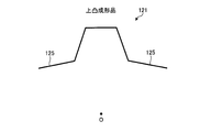
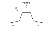
- Each of the upward convex molded product 121 and the downward convex molded product 127 has a groove shape portion 123 composed of a groove bottom portion 123a and a vertical wall portion 123b, and a flange portion 125 that curves out-of-plane direction. is doing.
- the flange portion 125 that curves out of the plane has a shape that curves so that the flange portion 125 is convex (upward convex) toward the groove bottom portion 123a.
- the flange portion 125 that curves out of plane has a shape that curves so that the flange portion 125 is concave (downward convex) toward the groove bottom portion 123a.
- FIG. 38A, FIG. 38B, FIG. 39A, and FIG. 39B are diagrams for explaining a mechanism for generating a spring back of a molded product molded by a conventional press molding method.
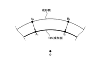
- FIG. 38A and FIG. 38B are explanatory views for explaining the change in the line length of the blank end (flange end) when the upward convex molded product 121 is formed by the conventional method.
- FIG. 39A and FIG. 39B are the same explanatory drawing about the case where the downward convex molded article 127 is shape
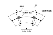
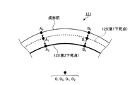
- 38A and 39A are cross-sectional views of the upper convex molded product 121 and the lower convex molded product 127 after molding (bottom dead center), respectively.
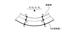
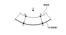
- FIG. 39B are diagrams for explaining the line length change of the blank end (flange end) before and after molding when the blank 21 (see FIG. 37) is viewed from the side.
- the line length of the blank end before molding is shown by a thin line
- the end of the flange 125 after molding that is, the line length of the flange end is shown by a thick line.
- the black point O is the center of curvature of the upper convex molded product 121 and the lower convex molded product 127.
- the radius of curvature of the flange end after molding is smaller than that of the blank before molding. Accordingly, the axial length of the flange end is shortened (A 0 B 0 ⁇ A 1 B 1 ). That is, the flange portion 125 is subjected to shrink flange deformation, and a compressive stress in the longitudinal direction remains in the flange portion 125 at the bottom dead center.
- the radius of curvature of the flange end after molding becomes larger than that of the blank before molding. Accordingly, the axial length of the flange end increases (C 0 D 0 ⁇ C 1 D 1 ). That is, the flange portion 125 is stretched flange deformation, and a tensile stress in the longitudinal direction remains in the flange portion 125 at the bottom dead center.
- the stress of the flange portion 125 is released at the time of die release, and after the stress release, the flange portion 125 of the upper convex molded product 121 undergoes stretch deformation, and the flange portion 125 of the lower convex molded product 127 contracts. Deformation occurs. As a result, in both the case of the upward convex molded product 121 (see FIG. 40A) and the case of the downward convex molded product 127 (see FIG. 40B), the curvature of curvature is smaller than the target product shape (curvature radius). The spring deformation (camber springback) occurs.
- FIG. 40A the upwardly convex molded product 121 after mold release is measured with a three-dimensional shape measuring instrument, and then the cross-section at the center in the longitudinal direction of the measured shape on CAD (computer aided design) software is the target product. It is illustrated by performing alignment so as to coincide with the same cross section of the shape.
- FIG. 40B illustrates the lower convex molded product 127 after mold release by performing the same process as that of the upward convex molded product 121 illustrated in FIG. 40A.
- the solid line indicates the target product shape (target product shape) of the upward convex molded product 121 or the downward convex molded product 127
- the dotted line indicates the upward convex molded product 121 or the downward convex molded product 127.
- the measurement shape is shown.
- press products such as product shapes with flanges on only one side, product shapes with different angles on the left and right sides of the vertical wall, product shapes with different vertical wall heights, and product shapes with different left and right flange widths.
- the molded product is twisted due to stress release at the time of mold release (see FIG. 16).
- the present inventors have studied a method for reducing the residual stress in the flange portion, and in the press molding process, the flange portion is subjected to a change larger than the line length change that occurs in the flange portion when the blank material is formed into a product shape. And then obtained knowledge that it is effective to perform molding so as to return the wire length of the flange portion to the product shape.
- the present invention has been made based on such knowledge, and specifically comprises the following constitution.
- the press molding method according to the present invention has a groove-shaped portion, and protrudes toward the groove bottom portion of the groove-shaped portion on at least one vertical wall portion of the pair of vertical wall portions forming the groove-shaped portion.
- a first molding step is performed using a mold, and a second molding step is performed using a second mold having a second groove shape molding portion and a second flange molding portion having the same inclination angle as the first groove shape molding portion.
- ⁇ 2 ⁇ 1 is set, and a compressive strain that reduces the length of the flange in the longitudinal direction generated in the first molding step is reduced in the second molding step. It shape
- the press molding method according to the present invention is the invention described above, wherein the vertical wall molding portion and the second flange molding portion in the second groove shape molding portion of the second mold are intersected.
- the flange width formed in the second forming step is L [mm]
- the effect of changing the springback is obtained, and the strain that can suppress wrinkles is suppressed.
- the upper limit value of the return amount ⁇ ( ⁇ > 0) is ⁇ max
- the ⁇ 1 and the ⁇ 2 satisfy the following expression (1).
- the press molding method according to the present invention has a groove-shaped portion, and at least one vertical wall portion of the pair of vertical wall portions forming the groove-shaped portion is recessed on the groove bottom side of the groove-shaped portion.
- a second mold having a second groove-shaped part and a second groove-shaped part having the same inclination angle as that of the first groove-shaped part is performed using a first mold having a flange-shaped part.
- a second molding step is performed using a mold, and passes through the intersection of the vertical wall molding portion and the first flange molding portion of the first groove-shaped molding portion of the first mold.
- the relationship between the curved surface having the same curvature as the curvature and the angle ⁇ 2 formed by the second flange molding portion is when the groove bottom side is negative from the curved surface and the opposite side is positive with respect to the curved surface.
- ⁇ 2 ⁇ 1 is set, and the tensile strain that extends the length of the flange portion in the longitudinal direction generated in the first forming step is set to the tensile length in the second forming step. It is characterized in that it is shaped so as to return by giving a deformation that shrinks.
- the press molding method according to the present invention is the invention described above, wherein the vertical wall molding portion and the second flange molding portion in the second groove shape molding portion of the second mold are intersected.
- the flange width formed in the second forming step is L [mm]
- the effect of changing the springback is obtained
- the strain return amount ⁇ ( ⁇ > that can suppress wrinkles When the upper limit value of 0) is ⁇ max , the ⁇ 1 and the ⁇ 2 satisfy the following expression (2).
- press molding method according to the present invention is the invention described in any of the above, wherein the first molding step is performed by foam molding.
- the press molding method according to the present invention is any one of the above-described inventions, wherein the first molding step is performed by draw forming.
- the press molding method according to the present invention is the invention according to any one of the above, wherein the molded product having a punch bottom portion at a groove bottom portion in the groove shape portion is formed by the first molding step. Is characterized in that press molding is performed by pressing a portion corresponding to the punch bottom of the blank with a pad.
- the press molding method according to the present invention is the invention according to any one of the above, wherein the first molding step and the second molding step are applied to any one flange portion of the pair of vertical wall portions. It is characterized by doing.
- the press molding method according to the present invention is the invention according to any one of the above, wherein the first molding step and the second molding step are applied to both flange portions of the pair of vertical wall portions. It is characterized by.
- the press molding method according to the present invention is the invention according to any one of the above, wherein the curved flange portion is provided over the entire axial length of the molded product,
- the relationship between ⁇ 1 and ⁇ 2 in one mold and the second mold is such that ⁇ 2 ⁇ 1 in a part of the mold axis direction in the first mold and the second mold. It is characterized by being set to.
- the press molding method according to the present invention is the invention according to any one of the above, wherein the curved flange portion is provided over the entire axial length of the molded product,
- the relationship between ⁇ 1 and ⁇ 2 in one mold and the second mold is set to ⁇ 2 ⁇ 1 over the entire length of the first mold and the second mold. It is characterized by being.
- the press molding method according to the present invention is the invention according to any one of the above, wherein the curved flange portion is provided in a part of the molded product in the axial direction,
- the relationship between ⁇ 1 and ⁇ 2 in the first die and the second die is ⁇ 2 only in the portion where the curved flange portion in the first die and the second die is molded.
- ⁇ 1 is set as a feature.
- the press molding method according to the present invention is the invention according to any one of the above, wherein the curved flange portion is provided in a part of the molded product in the axial direction,
- the relationship between ⁇ 1 and ⁇ 2 in one mold and the second mold is set to ⁇ 2 ⁇ 1 over the entire length of the first mold and the second mold. It is characterized by being.
- the press molding method according to the present invention has an effect of reducing three-dimensional springback such as twisting and bending without changing the product shape of a molded product having a flange portion with an upward or downward curved shape. .
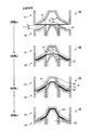
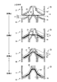
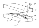
- FIG. 1 is an explanatory diagram of a press molding method (upward convex shape, foam molding) according to Embodiment 1 of the present invention.
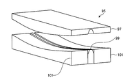
- FIG. 2A is a perspective view of the first mold (upward convex shape, foam molding) according to Embodiment 1 of the present invention.
- FIG. 2B is a cross-sectional view taken along the line AA of the first mold shown in FIG. 2A.
- FIG. 3A is a perspective view of the second mold (upward convex shape, foam molding) according to Embodiment 1 of the present invention.
- FIG. 3B is a cross-sectional view of the second mold shown in FIG. FIG.
- FIG. 4A is an explanatory diagram of a mechanism of the press molding method according to Embodiment 1 of the present invention, and is a cross-sectional view of an upward convex molded product at the first bottom dead center and the second bottom dead center.
- FIG. 4B is an explanatory diagram of a mechanism of the press molding method according to Embodiment 1 of the present invention, and is a diagram showing a change in the line length of the flange end.
- FIG. 5A is an explanatory diagram of the mechanism of the press molding method according to Embodiment 1 of the present invention, and is a diagram showing the relationship between stress and strain generated in the flange portion during molding.
- FIG. 5B is an explanatory diagram of the mechanism of the press molding method according to Embodiment 1 of the present invention, and is a diagram showing the inclination of the graph shown in FIG. 5A.
- FIG. 6A is an explanatory diagram of a mechanism relating to another aspect of the press molding method according to Embodiment 1 of the present invention.
- 6B is a diagram showing a change in the line length of the flange end shown in FIG. 6A.
- FIG. 7A is an explanatory diagram of a mechanism relating to a comparative example with respect to the press molding method according to Embodiment 1 of the present invention.
- FIG. 7B is a diagram showing a change in the line length of the flange end shown in FIG. 7A.
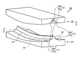
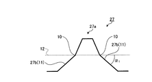
- FIG. 8A is a perspective view (downward convex shape, foam molding) of the first mold according to Embodiment 2 of the present invention.
- 8B is a cross-sectional view taken along the line CC of the first mold shown in FIG. 8A.
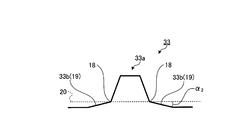
- FIG. 9A is a perspective view (downward convex shape, foam molding) of the second mold according to Embodiment 2 of the present invention.
- FIG. 9B is a cross-sectional view taken along line DD of the second mold shown in FIG. 9A.
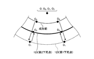
- FIG. 10A is an explanatory view of the mechanism of the press molding method according to Embodiment 2 of the present invention, and is a cross-sectional view of a downward convex molded product at the first bottom dead center and the second bottom dead center.
- FIG. 10A is an explanatory view of the mechanism of the press molding method according to Embodiment 2 of the present invention, and is a cross-sectional view of a downward convex molded product at the first bottom dead center
- FIG. 10B is an explanatory diagram of the mechanism of the press molding method according to Embodiment 2 of the present invention, and is a diagram showing a change in the line length of the flange end.
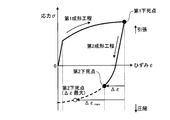
- FIG. 11A is an explanatory diagram of the mechanism of the press molding method according to Embodiment 2 of the present invention, and is a diagram illustrating the relationship between stress and strain generated in the flange portion during molding.
- FIG. 11B is an explanatory diagram of the mechanism of the press molding method according to Embodiment 2 of the present invention, and is a diagram showing the slope of the graph shown in FIG. 11A.
- FIG. 12A is an explanatory diagram of a mechanism relating to another aspect of the press molding method according to Embodiment 2 of the present invention.
- FIG. 12A is an explanatory diagram of a mechanism relating to another aspect of the press molding method according to Embodiment 2 of the present invention.
- FIG. 12B is a diagram showing a change in the line length of the flange end shown in FIG. 12A.
- FIG. 13A is an explanatory diagram of a mechanism relating to a comparative example of the press molding method according to Embodiment 2 of the present invention.
- FIG. 13B is a diagram showing a change in the line length of the flange end shown in FIG. 13A.
- FIG. 14 is an explanatory diagram of a press molding method (upward convex shape, foam molding, with pad) according to Embodiment 3 of the present invention.
- FIG. 15 is an explanatory diagram of a molded product (having a different flange width) that is a molding target according to the fourth embodiment of the present invention.
- FIG. 13A is an explanatory diagram of a mechanism relating to a comparative example of the press molding method according to Embodiment 2 of the present invention.
- FIG. 13B is a diagram showing a change in the line length of the flange end shown
- FIG. 16 is an explanatory diagram of a problem to be solved by the fourth embodiment of the present invention.
- FIG. 17 is a perspective view of a first mold (upward convex shape, foam molding, applied only on one side) according to Embodiment 4 of the present invention.
- FIG. 18 is an explanatory diagram of a press molding method (upward convex shape, foam molding, applied only on one side) according to Embodiment 4 of the present invention.
- FIG. 19 is a perspective view of a first mold (upward convex shape, draw molding) according to Embodiment 5 of the present invention.
- FIG. 20 is an explanatory diagram of a press molding method (upward convex shape, draw molding) according to Embodiment 5 of the present invention.
- FIG. 21 is a cross-sectional view showing an example of a product-shaped molded product to which the present invention is applicable.
- FIG. 22A is a diagram showing another example of a product-shaped molded product to which the present invention is applicable.
- FIG. 22B is a diagram showing still another example of a product-shaped molded product to which the present invention is applicable.
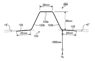
- FIG. 23A is an explanatory diagram of a molded product (upward convex shape) to be molded according to Example 1 of the present invention.
- FIG. 23B is a cross-sectional view of the molded product shown in FIG. 23A.
- FIG. 24A is an explanatory diagram of a molded product (downward convex shape) to be molded according to Example 2 of the present invention.
- FIG. 24B is a cross-sectional view of the molded product shown in FIG. 24A.
- FIG. 25 is an explanatory diagram of a press molding method (upward convex shape, draw molding, with pad) according to Example 3 of the present invention.
- FIG. 26 is an explanatory diagram of a conventional press die (upward convex shape, draw molding) according to Example 3 of the present invention.
- FIG. 27 is an explanatory diagram of a conventional press molding method (upward convex shape, draw molding) according to Example 3 of the present invention.
- FIG. 28 is a perspective view of a first mold (downward convex shape, draw molding) according to Embodiment 4 of the present invention.
- FIG. 29 is an explanatory diagram of a conventional press die (downward convex shape, draw molding) according to Example 4 of the present invention.
- FIG. 30 is an explanatory diagram of a molded product (in which the flange portion is inclined) according to the fifth embodiment of the present invention.
- FIG. 31 is an explanatory diagram of a molded product (with different flange widths) to be molded according to Example 6 of the present invention.
- FIG. 32 is a perspective view of a first mold (upward convex shape, draw molding, applying only the central portion) according to Embodiment 7 of the present invention.
- FIG. 33 is a perspective view of an upward convex molded product which is a molding target of the present invention.
- FIG. 34 is a perspective view of a downward convex molded product which is a molding target of the present invention.
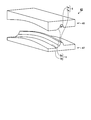
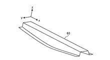
- FIG. 35 is an explanatory view of a problem to be solved by the present invention, and is a perspective view of a conventional press die (upward convex shape).
- FIG. 36 is an explanatory view of a problem to be solved by the present invention, and is a perspective view of a conventional press die (downward convex shape).
- FIG. 37 is an explanatory view of a problem to be solved by the present invention, and is an explanatory view of a conventional press molding method.
- FIG. 38A is a cross-sectional view of an upward convex molded product molded by a conventional press molding method.
- FIG. 38B is an explanatory diagram of changes in the line length of the flange end before and after molding an upward convex molded product by a conventional press molding method.
- FIG. 39A is a cross-sectional view of a downward convex molded product molded by a conventional press molding method.
- FIG. 39B is an explanatory diagram of a change in the line length of the flange end before and after molding a downward convex molded product by a conventional press molding method.
- FIG. 40A is an explanatory diagram of a problem to be solved by the present invention, and is an explanatory diagram of a springback of an upwardly convex molded product by a conventional press molding method.
- FIG. 40B is an explanatory view of a problem to be solved by the present invention, and is an explanatory view of a springback of a downward convex molded product by a conventional press molding method.
- the molded product targeted by the press molding method according to Embodiment 1 of the present invention includes a groove-shaped portion 123 extending in the longitudinal direction, and flange portions 125 provided on both sides of the groove-shaped portion 123.
- the groove-shaped portion 123 is formed by a groove bottom portion 123a and a pair of vertical wall portions 123b provided on both sides of the groove bottom portion 123a.
- the upward convex molded product 121 as described above is molded by the press molding method according to Embodiment 1 of the present invention.
- the press molding method according to the first embodiment is a first molding for molding an intermediate product (preformed part) having an intermediate shape (preformed shape) in which a greater change in line length occurs in the flange portion 125 than when molding into a product shape.
- press molding is performed using individual molds (first mold 1 and second mold 3). The second mold 3 will be described with reference to FIGS. 1, 2A, 2B, 3A, and 3B.
- die 1 is a metal mold
- the first die 5 is formed on both sides of the first die side groove shape forming portion 5a for forming the groove shape portion 123 of the upward convex molded product 121 (see FIG. 33) and the first die side groove shape forming portion 5a.
- the first die side flange forming portion 5b for forming the flange portion 125 of the upward convex molded product 121 is provided.
- the first punch 7 includes a first punch side groove shape forming portion 7a that forms the groove shape portion 123 of the upward convex molded product 121 in cooperation with the first die side groove shape forming portion 5a, and the first die side.
- the first punch side flange forming portion 7b for forming the flange portion 125 of the upward convex molded product 121 in cooperation with the flange forming portion 5b.
- the first die side groove shape forming portion 5 a and the first punch side groove shape forming portion 7 a are the first groove shape forming portion 9 of the first mold 1.
- the flange forming part 5 b on the first die side and the flange forming part 7 b on the first punch side are the first flange forming part 11 of the first mold 1.
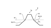
- the same curvature as the curvature of the flange portion 125 in the intersecting portion 10 passes through the intersecting portion 10 between the vertical wall forming portion and the first flange forming portion 11 in the first groove shape forming portion 9.
- the angle formed between the curved surface 12 and the first flange forming portion 11 (hereinafter referred to as “first inclination angle ⁇ 1 ”) is set to a predetermined size.
- die 3 is a metal mold
- the second die 13 is formed on both sides of the second die side groove shape forming portion 13a and the second die side groove shape forming portion 13a having the same shape as the first die side groove shape forming portion 5a.
- the second punch 15 cooperates with the second punch side groove shape forming portion 15a having the same shape as the first punch side groove shape forming portion 7a and the flange forming portion 13b on the second die side so as to form the flange portion 125. And a flange forming portion 15b on the second punch side for forming into a product shape.
- the second die side groove shape forming portion 13 a and the second punch side groove shape forming portion 15 a are the second groove shape forming portion 17 of the second mold 3.
- the second die side flange molding part 13 b and the second punch side flange molding part 15 b are the second flange molding part 19 of the second mold 3.
- An angle formed between the curved surface 20 and the second flange forming portion 19 (hereinafter referred to as “second inclination angle ⁇ 2 ”) is set to a predetermined size.
- second inclination angle ⁇ 2 is set to a predetermined size.
- the first inclination angle ⁇ 1 and the second inclination angle ⁇ 2 are negative on the groove bottom side from the curved surface with respect to the curved surfaces (curved surface 12 and curved surface 20) described above, The opposite side is positive.
- Figure 2B as shown in FIG. 3B, the second inclination angle alpha 2 is to be smaller than the first inclination angle alpha 1 (first inclination angle alpha 1> second inclination angle alpha 2) are set.
- the first molding step is a step of press-molding the blank 21 of the upward convex molded product 121 into an intermediate product using the first mold 1.
- the first mold 1 receives the blank 21 between the first die 5 and the first punch 7 as in the step a shown in FIG.
- the blank 21 is placed on the first punch 7.
- the first die 5 moves toward the first punch 7 and approaches the blank 21.
- the first mold 1 press-molds the blank 21 into an intermediate product with the first die 5 and the first punch 7 as shown in the step b shown in FIG.
- the first groove shape forming portion 9 is formed by pressing the blank 21 with the groove shape forming portion 5a on the first die side and the groove shape forming portion 7a on the first punch side.
- a groove-shaped portion 123 is formed.
- the first flange forming portion 11 forms the flange portion 125 in the blank 21 by press-molding the blank 21 with the flange forming portion 5b on the first die side and the flange forming portion 7b on the first punch side. To do.
- the blank 21 is formed into an intermediate product having the groove shape portion 123 and the flange portion 125 described above.
- the groove-shaped portion 123 is formed in the same shape as the product shape by the first groove-shaped forming portion 9, and the inclination angle of the flange portion 125 with respect to the curved surface 12 (see FIGS. 2A and 2B) is the first flange forming.
- the part 11 is molded at the first inclination angle ⁇ 1 .
- the second molding step is a step of using the second mold 3 to press-mold the intermediate product having the intermediate shape in the first molding step described above into the upward convex product 121 having a product shape.
- the second mold 3 is placed between the second die 13 and the second punch 15 in the intermediate product, that is, the intermediate shape by the first molding step described above.
- the upper convex molded product 121 is received.
- the upper convex molded product 121 having an intermediate shape is placed on the second punch 15.
- the second die 13 moves toward the second punch 15 and comes close to the intermediate convex upper convex molded product 121.
- the second mold 3 is formed by using the second die 13 and the second punch 15 to convert the upper convex product 121 into an upper convex product 121 having an intermediate shape. Press molding.
- the second groove shape molding part 17 press-molds the intermediate convex upper convex molded product 121 with the second die side groove shape molding part 13a and the second punch side groove shape molding part 15a.
- the groove-shaped portion 123 of the upward convex molded product 121 is formed into a product-shaped groove-shaped portion 123 having a groove bottom portion 123a and a vertical wall portion 123b.
- the second flange forming portion 19 is formed by press-molding an upper convex molded product 121 having an intermediate shape with the flange forming portion 13b on the second die side and the flange forming portion 15b on the second punch side.
- the flange part 125 of the molded product 121 is molded into the flange part 125 having the second inclination angle ⁇ 2 .
- the upward convex molded product 121 is molded from the above-described intermediate shape to the product shape.
- the groove-shaped portion 123 is sandwiched by the second groove-shaped molded portion 17, and the inclination angle of the flange portion 125 with respect to the curved surface 20 (see FIGS. 3A and 3B) is second inclined by the second flange-shaped portion 19. Molded at the same inclination angle as the angle ⁇ 2 .
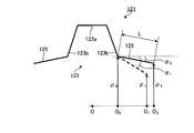
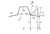
- FIG. 4A is a cross-sectional view of the upward convex molded product 121 at the bottom dead center (first bottom dead center) of the first molding step and the bottom dead center (second bottom dead center) of the second molding step.
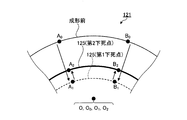
- FIG. 4B is a diagram showing a change in the line length of the blank end (flange end) when the blank 21 (upward convex molded product 121) is viewed from the side.
- the flange portion 125 at the first bottom dead center is shown by a broken line
- the flange portion 125 at the second bottom dead center is shown by a solid line
- the flange portion 125 at the first bottom dead center is shown only on one side.
- the inclination angle of the flange portion 125 at the first bottom dead center is the first inclination angle ⁇ 1
- the inclination angle of the flange portion 125 at the second bottom dead center is the second inclination angle ⁇ 2.
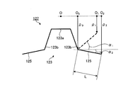
- the center of curvature at the intersection of the vertical wall portion 123b and the flange portion 125 is O 0 and the radius of curvature is ⁇ 0 [mm].
- the center of curvature of the flange end at the first bottom dead center is O 1 and the radius of curvature is ⁇ 1 [mm].
- the center of curvature of the flange end at the second bottom dead center is O 2 , the radius of curvature is ⁇ 2 [mm], and the flange width of the product shape is L [mm].
- the line length of the blank end before molding is shown by a thin solid line
- the line length of the flange end at the first bottom dead center is shown by a broken line
- the line length of the flange end at the second bottom dead center is a thick solid line. Is shown.
- FIG. 5A is a stress-strain curve showing a relationship between stress and strain generated in the flange portion 125 during molding.
- the vertical axis represents stress ⁇ and the horizontal axis represents strain ⁇ .
- the stress value when the stress value is positive, it means a tensile stress, and when the stress value is negative, it means a compressive stress.
- FIG. 5B is a graph showing the slope of the graph of FIG. 5A (the gradient d ⁇ / d ⁇ of the strain change amount and the stress with respect to the strain change amount).
- the horizontal axis represents the strain ⁇
- the vertical axis represents the stress gradient d ⁇ / d ⁇ with respect to the strain.
- the mode of change in the line length of the flange portion 125 during molding differs between the case of the first inclination angle ⁇ 1 > the second inclination angle ⁇ 2 and the case of the first inclination angle ⁇ 1 ⁇ the second inclination angle ⁇ 2.
- the mechanism of the press forming method when the first inclination angle ⁇ 1 > the second inclination angle ⁇ 2 will be described.
- the compressive stress applied to the flange portion 125 in the first molding process is greatly reduced.
- the stress ⁇ remaining in the flange portion 125 changes from a compressive stress to a tensile stress.
- the present invention utilizes the characteristic that the stress changes sensitively with respect to the return of a slight strain.
- the press molding method according to Embodiment 1 of the present invention when the upwardly convex product 121 having a product shape is molded, in the first molding step, the molding is once performed so that the flange wire length is shorter than the product shape. In the second molding step, the flange wire length is slightly increased.
- molding process is returned by the 2nd shaping
- the compressive stress of the flange portion 125 is reduced. As a result, the residual stress of the flange portion 125 is reduced, thereby reducing the spring back.
- Curvature radius [rho 2 of the flange end of the radius of curvature [rho 1 and the second bottom dead center of the flange end of the first bottom dead center shown in FIG. 4A is represented by the following formula (3) and (4).
- the first inclination angle alpha 1 is represented by the following formula (6).
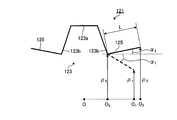
- the present invention is not limited to this, and as shown in FIG. 6A, the first inclination angle ⁇ 1 is positive and the second inclination angle ⁇ 2 is negative, or both the first inclination angle ⁇ 1 and the second inclination angle ⁇ 2 are used. Even if it is negative, if the first inclination angle ⁇ 1 > the second inclination angle ⁇ 2 , the change in the line length of the flange portion 125 is as described above, for example, as shown in FIG. 6B.
- the flange portion 125 may be inclined with respect to the curved surface 20).
- the longitudinal line length of the flange portion 125 is shortened in the first forming step ( A 0 B 0 ⁇ A 1 B 1 ).
- the flange part 125 receives a compressive strain.
- the longitudinal length of the flange portion 125 is further shortened as shown in FIG. 7B (A 1 B 1 ⁇ A 2 B 2 ). Therefore, the strain 125 does not return the strain ⁇ to the flange portion 125 formed in this manner, and therefore, the effect of reducing the compressive stress remaining in the flange portion 125 cannot be obtained. As a result, the spring back is not reduced.
- FIG. 6A, FIG. 6B, FIG. 7A, and FIG. 7B are the same as those shown in FIG. 4A, except that the first inclination angle ⁇ 1 and the second inclination angle ⁇ 2 are different in size and magnitude. It is the same as that shown in 4B.
- the same components are denoted by the same reference numerals.
- the gradient d ⁇ / d ⁇ is large in the region where the strain return amount ⁇ from the first bottom dead center is small, but the gradient d ⁇ / d ⁇ is small in the region where the strain return amount ⁇ is large.
- the strain return amount ⁇ is small, the amount of change in the stress ⁇ with respect to the amount of change in the strain ⁇ increases, and in the region where the strain return amount ⁇ is large, the amount of change in the stress ⁇ with respect to the change amount of the strain ⁇ I understand that In a region where the strain return amount ⁇ is large, even if the strain ⁇ is changed, the change amount of the stress ⁇ with respect to the change amount is small, and therefore the effect of changing the springback is small.
- the strain return amount ⁇ increases.
- the strain return amount ⁇ is large, the amount of compressive strain of the flange portion 125 in the first molding step increases, so that wrinkles may occur in the flange portion 125. Therefore, there is an upper limit value for the strain return amount ⁇ that is effective in changing the springback and can suppress wrinkles of the flange portion 125.
- this upper limit value is ⁇ max , the range of the strain return amount ⁇ is expressed by the following equation (7).
- the first inclination angle alpha 1 After having organized the first inclination angle alpha 1 by substituting equation (7) into equation (6), the first inclination angle alpha 1 in order to obtain the effect of reducing the compressive stress of the flange portion 125> second inclination angle alpha In consideration of 2 , the range of the first inclination angle ⁇ 1 is expressed by the following equation (1).
- the Young's modulus of the blank 21 is set to E [MPa]
- the tensile strength of the blank 21 is set to It is given by 4 ⁇ TS / E as ⁇ TS [MPa].
- the forming is performed such that the flange wire length is once shorter than the product shape, and the second forming step is slightly performed.
- the distortion generated in the first molding step in the flange portion 125 is slightly returned in the second molding step, and as a result, the compressive stress of the flange portion 125 is reduced, resulting in the flange portion.
- the residual stress of 125 is reduced, thereby reducing springback.
- the first inclination angle ⁇ 1 within the range of the formula (1), the amount of spring back can be controlled without generating wrinkles in the flange portion 125.
- the downward convex molded product 127 includes a first die 23 (see FIG. 8A) composed of a first die 25 and a first punch 27, and a second die 29 composed of a second die 31 and a second punch 33. (See FIG. 9A).
- the first metal mold 23 and the second metal mold 29 are different from the first metal mold 1 and the second metal mold 3 (see FIGS. 2A and 3A) of the first embodiment except that the bending direction is different. Is the same.
- the first die side groove shape forming portion 25a and the first die side flange forming portion 25b are different from each other in the direction of the curve, except for the first die side.
- the groove-shaped forming portion 5a and the flange forming portion 5b on the first die side is different from each other in the curve direction, and the first punch-side groove-shaped part is in the first embodiment. 7a and the flange forming part 7b on the first punch side.
- the groove shape forming part 31a on the second die side and the flange forming part 31b on the second die side are different in the curve direction, and the groove shape on the second die side in the first embodiment is different.
- the molding part 13a and the second die side flange molding part 13b are respectively the same.
- the second punch side groove shape forming portion 33a and the second punch side flange shape forming portion 33b are different from each other in the curve direction, and the second punch side groove shape forming portion in the first embodiment. 15a and the flange forming part 15b on the second punch side. 8A and 9A, the same reference numerals are given to the same components as those in FIGS. 2A and 3A. 8B, which is a cross-sectional view of the first mold 23 shown in FIG. 8A, and FIG. 9B, which is a cross-sectional view of the second mold 29 shown in FIG. 9A, are the same as those in FIGS. 2B and 3B. Are given the same reference numerals.
- the downward convex molded product 127 differs from the case of the upward convex molded product 121 of the first embodiment in the aspect of the change in the line length of the flange portion 125, so paying attention to this point, the mechanism of the press molding method according to the second exemplary embodiment Will be described with reference to FIGS. 10A, 10B, 11A, and 11B.
- 10A, FIG. 10B, FIG. 11A, and FIG. 11B are explanatory views of the mechanism of the press molding method according to Embodiment 2 of the present invention. 10A and 10B, the same symbols are attached to the same components as those in FIGS. 4A and 4B.
- the mode of change in the line length of the flange portion 125 during molding differs between the case of the first inclination angle ⁇ 1 > the second inclination angle ⁇ 2 and the case of the first inclination angle ⁇ 1 ⁇ the second inclination angle ⁇ 2.
- the mechanism of the press forming method when the first inclination angle ⁇ 1 > the second inclination angle ⁇ 2 will be described.
- the tensile strain generated in the flange portion 125 in the first molding step is returned to the compression side by a strain return amount ⁇ (from the first bottom dead center).
- a strain return amount ⁇ from the first bottom dead center.
- the stress applied to the flange portion 125 in the first molding process is reduced.
- the stress ⁇ remaining in the flange portion 125 is changed from a tensile stress to a compressive stress.
- the first inclination angle ⁇ 1 is expressed by the following expression (11).
- the present invention is not limited to this, and as shown in FIG. 12A, the first inclination angle ⁇ 1 is positive and the second inclination angle ⁇ 2 is negative, or both the first inclination angle ⁇ 1 and the second inclination angle ⁇ 2 are present. Even if it is negative, if the first inclination angle ⁇ 1 > the second inclination angle ⁇ 2 , the manner of changing the line length of the flange portion 125 is the same as shown in FIG. 12B, for example.
- the press molding method according to Embodiment 2 of the present invention an effect of reducing the tensile stress of the flange portion 125 can be obtained.
- the longitudinal line length of the flange portion 125 is increased in the first molding step ( C 0 D 0 ⁇ C 1 D 1 ). Thereby, the flange part 125 receives a tensile strain. Thereafter, when the flange portion 125 is formed into a product shape in the second forming step, the longitudinal length of the flange portion 125 is further increased as shown in FIG. 13B (C 1 D 1 ⁇ C 2 D 2 ).
- FIG. 12A, FIG. 12B, FIG. 13A, and FIG. 13B are the same as FIG. 10A and FIG. 10 except that the first inclination angle ⁇ 1 and the second inclination angle ⁇ 2 are different in size and magnitude. It is the same as that shown in 10B.
- the same components are denoted by the same reference numerals.
- the preferred range of the first inclination angle ⁇ 1 was examined based on the gradient d ⁇ / d ⁇ (see FIG. 11B) of the stress-strain diagram. Will be described.
- the gradient d ⁇ / d ⁇ is large in the region where the strain return amount ⁇ from the first bottom dead center is small, but is small in the region where the strain return amount ⁇ is large, as in the first embodiment.
- the change amount of the stress ⁇ with respect to the change in the strain ⁇ is large, and in the region where the strain return amount ⁇ is large, the change amount of the stress ⁇ is small.
- the change amount of the stress ⁇ with respect to the change amount is small, and therefore the effect of changing the springback is small.
- the strain return amount ⁇ increases. If the strain return amount ⁇ is large, the amount of tensile strain of the flange portion 125 in the first molding step increases, so that there is a possibility that the flange portion 125 may be fractured. Further, when the strain return amount ⁇ is large, wrinkles may occur in the flange portion 125 in the second molding step. Therefore, there is an upper limit value for the strain return amount ⁇ that is effective in changing the springback and that can suppress cracks and wrinkles of the flange portion 125. When this upper limit value is ⁇ max , the range of the strain return amount ⁇ is expressed by the following expression (7) as in the case of the first embodiment.
- the upper limit value ⁇ max of the strain return amount ⁇ that can suppress such wrinkles of the flange portion 125 is, for example, when the wrinkle generation limit of the flange portion 125 is experimentally obtained, the Young's modulus of the blank 21 is E [MPa], The tensile strength of the blank 21 is given by 4 ⁇ TS / E, with ⁇ TS [MPa].
- the flange portion 125 is once molded so that the line length of the flange portion 125 becomes longer than the product shape.
- the wire length is slightly shortened.
- molding process will be returned slightly in a 2nd shaping
- the residual stress of the flange portion 125 is reduced, thereby reducing the spring back.
- the first inclination angle ⁇ 1 within the range of the expression (2), the amount of spring back can be controlled without causing cracks or wrinkles in the flange portion 125.
- a first mold 35 according to the third embodiment is shown in stages a and b of the press molding method shown in FIG.
- the first die 37 of the first mold 35 has the points 39a and b of the press molding method shown in FIG. 1 and the first die 5 of the first mold 1 shown in FIG. Is the same. Therefore, in steps a and b in FIG. 14, portions other than the pads 39 of the first mold 35 are denoted by the same reference numerals as in steps a and b in FIG. 1 and FIG. 2A.
- the pad 39 is provided so as to be able to appear and retract with respect to the first die 37, and sandwiches a portion corresponding to the groove bottom portion of the blank 21 in cooperation with the first punch 7.
- the second mold 3 similar to that shown in FIG. 3A is used as in the first embodiment.
- the intermediate-shaped upward convex molded product 121 (intermediate product) is press-molded into a product shape.
- the first mold with a pad can be used for the press molding of the lower convex molded product 127 as well.
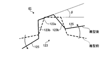
- the press molding method according to the fourth embodiment is effective when molding a product having different widths of both flange portions 125, such as the molded product 41 shown in the sectional view of FIG.
- the widths of both flange portions 125 are different, so that residual stress accumulated in the flange portion 125 at the bottom dead center (when the molded product 41 has an upward convex shape, compression is performed. Stress) is different between both flanges 125. Due to this, the balance of the moment acting on the molded product 41 is lost, and as a result, the torsional deformation as shown in FIG. In FIG.
- the shape of the molded product 41 before release is indicated by a broken line, and the shape after release is indicated by a solid line. Therefore, in the press molding method according to the fourth embodiment, in order to balance the residual stresses in both flange portions 125, the one flange portion 125 is molded so as to give the strain return proposed in the present invention. Shall be performed.
- FIG. 17 An example of a mold used in the first molding step in the fourth embodiment for performing such molding is shown in FIG.
- a first mold 43 shown in FIG. 17 is an example in which steps a and b of the press molding method shown in FIG. 1 and a part of the first mold 1 shown in FIG. 2A are changed.
- the same reference numerals are assigned to the same parts as those of the mold 1.
- the first mold 43 molds only the flange portion 125 having the longer flange width out of both flange portions 125 (see FIG. 15) of the molded product 41 to the first inclination angle ⁇ 1 . It is configured to be able to. That is, as shown in FIG.
- the first mold 43 includes a first die 45 in which a first die side flange molding portion 5b is provided only on one side of the first die side groove shape molding portion 5a, and A first punch 47 having a first punch side flange forming portion 7b provided only on one side of the first punch side groove forming portion 7a.
- the second convex mold 3 similar to that of the first embodiment is used.
- a molded product 121 (intermediate product) is press-molded into a product shape.
- the press molding method using the first metal mold 43 and the second metal mold 3, that is, the press molding method according to the fourth embodiment will be described with reference to FIG.
- the first molding process (stages a and b) and the second molding process (stages c and d) are sequentially performed, and the blank 21 is manufactured as a product.
- the product is formed into an upward convex molded product 121 having a shape.
- the first mold 43 receives the blank 21 between the first die 45 and the first punch 47, and the blank 21 is received.
- the first die 45 and the first punch 47 are press-molded into an intermediate convex product 121 (intermediate product).
- the first groove shape forming portion 9 is formed by pressing the blank 21 with the groove shape forming portion 5a on the first die side and the groove shape forming portion 7a on the first punch side.
- a portion 123 is formed.
- the flange width of the first flange forming portion 11 is different from that of the blank 21 by press-molding the blank 21 with the flange forming portion 5b on the first die side and the flange forming portion 7b on the first punch side.
- a pair of flange portions 125 is formed.
- the blank 21 is formed into an intermediate-shaped upward convex product 121 (intermediate product) having the above-described groove-shaped portion 123 and a pair of flange portions 125 having different flange widths.
- the first mold 43 uses the first flange forming portion 11 on one side, and the inclination angle of only the flange portion 125 having the wider flange width of the pair of flange portions 125 is the first inclination angle ⁇ . Molded to have the same angle as 1 .
- the second mold 3 molds the intermediate-shaped upper convex molded product 121 formed in the first molding step into a product shape.
- the second flange forming portion 19 forms the flange portion 125 having a wide flange width into a product shape.
- the distortion of the flange portion 125 having the wide flange width is returned, and as a result, the compressive stress remaining in the flange portion 125 having the wide flange width is reduced.
- the residual stress accumulated in the flange portion 125 having a wide flange width can be reduced by the second molding step in the fourth embodiment. This makes it possible to balance the residual stress of the flange portion 125 having a wide flange width and the residual stress accumulated in the flange portion 125 having a narrow flange width. As a result, since the moment acting on the molded product 41 at the second bottom dead center is balanced, the torsional deformation of the molded product 41 after releasing (upward convex molded product 121 in FIG. 18) can be reduced.
- the press molding according to the fourth embodiment of the present invention may be performed on the flange having a narrower flange width or may be performed on both flange portions 125 depending on circumstances. Further, the press molding method according to the fourth embodiment can be applied regardless of whether the molded product has an upward convex shape or a downward convex shape.
- a first mold 49 shown in FIG. 19 is used to perform draw molding.
- a first mold 49 shown in FIG. 19 is obtained by changing steps a and b of the press molding method shown in FIG. 1 and a part of the first mold 1 shown in FIG. 2A.
- the same reference numerals are given to the same parts as those of the one mold 1.
- the first mold 49 is for forming the upward convex molded product 121, and includes a die 51, a punch 53, and a blank holder 55 as shown in FIG.
- the first groove shape forming portion 9 includes the groove shape forming portion of the die 51 (the groove shape forming portion 5a on the first die side) and the groove shape forming portion of the punch 53 (on the first punch side). This is realized by the groove-shaped forming part 7a).
- the first flange forming portion 11 is realized by the flange forming portion of the die 51 (the flange forming portion 5b on the first die side) and the flange forming portion of the blank holder 55 (the flange forming portion 7b on the first punch side). .
- the first inclination angle ⁇ 1 of the first flange forming portion 11 in the fifth embodiment is set to the same angle as the first inclination angle ⁇ 1 of the first mold 1 in the first embodiment shown in FIG. 2B. Yes.
- the die 51 can have the same shape as the first die 5 (see FIG. 2A) of the first mold 1 in the first embodiment.
- the punch 53 is provided so as to be individually operable with respect to the blank holder 55.
- the upper part of the punch 53 constitutes the first punch side groove shape forming portion 7a, and is inserted into the groove shape forming portion of the die 51 (the first die side groove shape forming portion 5a).
- 121 groove-shaped portions 123 are formed.
- the blank holders 55 are provided on both sides of the punch 53, hold the blank 21 in cooperation with the die 51, and mold the flange portion 125 of the upward convex molded product 121.
- the second molding step (second stage 3 in FIG. 1) is the same as in the first embodiment. c, d and FIG. 3A), the intermediate-shaped upward convex molded product 121 is press-molded into a product shape.
- the first mold 49 receives the blank 21 between the die 51 and the blank holder 55, as in the step a shown in FIG.
- the blank 21 is placed on the upper surface of the punch 53.
- the first mold 49 sandwiches the blank 21 by the die 51 and the blank holder 55 as in the step b shown in FIG.
- the blank holder 55 cooperates with the die 51 so as to sandwich the blank 21 between the flange forming portion 5b on the first die side and the flange forming portion 7b on the first punch side. Hold it.
- the first die 49 press-molds the blank 21 sandwiched between the die 51 and the blank holder 55 with the punch 53 as shown in step c shown in FIG.
- the punch 53 press-molds the sandwiched blank 21 while moving upward toward the groove-shaped molding portion 5a on the first die side.
- the first mold 49 forms the blank 21 into the intermediate convex upper convex molded product 121 by the die 51, the punch 53, and the blank holder 55, as shown in step d shown in FIG. 20.
- the punch 53 continues to move upward to bring the first punch-side groove-shaped part 7a close to the first die-side groove-shaped part 5a, and the first groove-shaped part 9 causes the blank 21 to move.
- the groove-shaped portion 123 (see FIG. 33) of the intermediate-shaped upper convex molded product 121 is formed.
- the die 51 and the blank holder 55 maintain the state in which the blank 21 is sandwiched by the first flange forming portion 11 (the flange forming portion 5b on the first die side and the flange forming portion 7b on the first punch side), Thereby, the flange part 125 (refer FIG. 33) of both sides is formed among the upward convex molded articles 121 of intermediate shape.
- the intermediate shape of the upward convex molded product 121 and when the first mold 1 is used for the foam molding see FIG. 1.
- the first inclination angle ⁇ 1 of the first flange molding portion 11 of the first mold 49 is set to the same angle as that of the first mold 1, the first mold 1 is used.
- the effect of returning the distortion of the flange portion 125 in the second molding process can be obtained also in the fifth embodiment.
- FIG. 21 shows a plurality of examples of product-shaped cross-sections of molded products to which the present invention can be applied.
- the product shape (cross-sectional shape) of the molded product to which the present invention can be applied is divided into nine types T1 to T9 for each configuration of the flange portion and the vertical wall portion of the molded product.
- types T1 to T9 are product shapes of molded products having flange portions on both of the vertical wall portions.
- types T1 to T6 are product shapes of molded products in which the vertical wall portion is vertical.
- Types T2 and T5 are product shapes in which the vertical wall portion is inclined in the same manner as the above-described molded products (upward convex molded product 121, downward convex molded product 127).
- Types T3 and T6 are product shapes of molded products in which both vertical wall portions are inclined to form a shape without a flat portion at the top. In order to form a product-shaped cross section of types T3 and T6, a punch having a curved tip may be used.
- types T7 to T9 are product shapes of a molded product having a flange portion only on one of a pair of vertical wall portions constituting the groove shape portion.
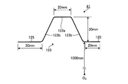
- the product shape of the molded product to which the present invention is applicable may be the product shape of the molded product 61 in which only the flange portion is curved in the upward convex direction, as shown in the examples in FIGS. 22A and 22B,
- the product shape of the molded product 63 in which only the flange portion is curved in the downward convex direction may be used.
- the product shape of the molded product shown in any of FIGS. 21, 22A and 22B, that is, the product shape of the molded product to which the present invention can be applied, is limited with respect to the width, length, and height position of the flange portion. There is no. Further, the left and right flange portions may have different widths and lengths.
- the second forming step is exemplified by moving the second die downward and approaching the second punch, but the present invention is not limited to this.
- either of the second punch and the second die may be moved relatively close to each other, and the second punch may be moved closer to the second die.
- top and bottom of the first die of the first mold and the first punch are interchanged, or the top and bottom of the second die and the second punch of the second mold are interchanged, or the first of the first mold
- the top and bottom of the first die and the first punch may be interchanged and the top and bottom of the second die and the second punch of the second mold may be interchanged.
- the die in which the die can be moved up and down is taken as an example, but the moving direction of the die is not limited to the up and down direction.
- first groove shape molding portion and the second groove shape molding portion have the same shape
- first groove shape molding portion and the second groove shape molding portion are different. It may be a shape.
- a bead may be provided in the first groove shape forming portion and the bead may be crushed by the second groove shape forming portion.
- the above description is a description of a press molding method for press molding a molded product in which a curved flange portion is provided in a part of the axial direction of the molded product, and the first mold and the first mold
- the relationship between the first tilt angle ⁇ 1 and the second tilt angle ⁇ 2 in the second mold is such that the first tilt angle ⁇ 1 > second over the entire length of the first mold and the second mold.
- the press forming method set to the inclination angle ⁇ 2 It was an explanation of the press forming method set to the inclination angle ⁇ 2 .
- the present invention is not limited to the above, and the relationship between the first inclination angle ⁇ 1 and the second inclination angle ⁇ 2 described above is a curved flange of the first mold and the second mold. It may be set so that the first inclination angle ⁇ 1 > the second inclination angle ⁇ 2 may be set only at the part where the part is formed (see Example 7 and FIG. 32 described later).
- the above description is a description of a press molding method for press molding a molded product in which a curved flange portion is provided in a part in the axial direction of the molded product.
- the present invention can also be applied to a case where a molded product in which the portion is provided over the entire axial length of the molded product is press-molded.
- the relationship between the first inclination angle ⁇ 1 and the second inclination angle ⁇ 2 is such that the first inclination angle ⁇ is applied only to the portion of the first mold and the second mold where the curved flange portion is formed. It may be set such that 1 > second inclination angle ⁇ 2 , or may be set so that first inclination angle ⁇ 1 > second inclination angle ⁇ 2 over the entire length.
- Example 1 of the present invention will be described.
- Example 1 since the experiment for confirming the effect by the press molding method of this invention was conducted, the result is demonstrated below.
- the experimental method will be outlined.
- Experiments for confirming the effect of the first inclined angle alpha 1 performs a first forming step by changing the first mold 1 first inclination angle alpha 1 (see FIG. 2A) (see FIG. 2B) (Fig. 1) (steps a and b in FIG. 1), the second molding process is performed in the second mold 3 (see FIG. 3A) (see steps c and d in FIG. 1), and the spring of the upper convex molded product 121 is formed. The amount of back is compared.
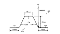
- the size of the upward convex molded product 121 to be molded is a product length of 1000 [mm], a bending direction height of 30 [mm], and a groove bottom.
- the width of 123a is 20 [mm]
- the width of the flange portion 125 is 25 [mm]
- the curvature radius of the intersection between the vertical wall portion 123b and the flange portion 125 is 1000 [mm].
- Both of these blanks had a plate thickness of 1.2 [mm] and a Young's modulus of 210000 [MPa].
- a 1000 ton hydraulic press was used as the press forming machine.
- the upper limit value of the first inclination angle ⁇ 1 is 26.4 [°] when a 590 MPa class material is used as a result of calculation assuming that ⁇ max of the equation (1) is given by 4 ⁇ TS / E, and is 1180 MPa. In the case of using a grade material, it was 61.6 [°].
- Group 1 is a group obtained by press-molding a 590 MPa class material without a pad.
- press molding of Group 1 press molding of Invention Example 1, Invention Example 2, Conventional Example 1, Comparative Example 1 and Comparative Example 2 was performed.
- Invention Example 1 and Invention Example 2 are press moldings in the case where the range of the first inclination angle ⁇ 1 is set to satisfy the formula (1).
- Comparative Example 1 is press molding when the first inclination angle ⁇ 1 ⁇ the second inclination angle ⁇ 2 .
- Comparative Example 2 is press forming when the upper limit (26.4 [°]) of the first inclination angle ⁇ 1 is exceeded.
- Group 2 is a group obtained by press-molding a 590 MPa class material with a pad.
- group 2 press molding the press molding of Invention Example 3 and Conventional Example 2 was performed.
- Invention Example 3 is the same as Invention Example 2 except that a pad is used.
- Conventional Example 2 is the same as Conventional Example 1 except that a pad is used.
- the first molding step (see steps a and b in FIG. 14) is performed using the first mold 35, and the second inclination angle ⁇ 2 of the second mold 3 is set to 0 [°.
- the second molding step was performed.
- Group 3 is the same as Group 1 except that a 1180 MPa class material was used. That is, Example 1 of the present invention, Example of the present invention, except that 1180 MPa class materials were used for the press forming of Invention Example 4, Invention Example 5, Conventional Example 3, Comparative Example 3 and Comparative Example 4 performed as Group 3. 2. Same as Conventional Example 1, Comparative Example 1, and Comparative Example 2, respectively.
- Group 4 is the same as Group 2 except that a 1180 MPa class material is used. That is, each press molding of Invention Example 6 and Conventional Example 4 performed as group 4 is the same as Invention Example 3 and Conventional Example 2 except that a 1180 MPa class material was used.
- the formed upward convex molded product 121 was measured with a three-dimensional shape measuring instrument. Thereafter, as shown in FIG. 40A, after the alignment is performed so that the cross-section at the center in the longitudinal direction of the measurement shape coincides with the same cross-section of the product shape on the CAD software, the measurement at the component end of the upward convex molded product 121 is performed. As a Z coordinate difference between the shape and the product shape, the amount of splash ⁇ z was calculated. In Example 1, the amount of splash ⁇ z was used as an index for the deformation of the upward convex molded product 121 due to the spring back. The positive amount ⁇ z means that the component has been deformed upward if it is positive, that means that the component has been deformed downward if it is negative, and that the spring back is small if the absolute value is small.
- Table 1 summarizes each press molding condition in Example 1, the upper limit of the first inclination angle ⁇ 1 , and the shape evaluation result of the upward convex molded product 121 molded under each press molding condition.
- Table 1 shows whether wrinkles are generated (O, x) and the amount of splash ⁇ z [mm] of the upwardly convex molded product 121.
- a circle indicates “no wrinkles”, and a cross indicates “wrinkles”.
- wrinkles are generated in the upper convex molded article 121 by applying the method of the present invention to the upper convex molded article 121 and press-molding the first inclination angle ⁇ 1 within the range of the formula (1).
- the spring back of the upward convex molded product 121 could be reduced.
- upward convex molding is performed. The spring back of the product 121 could be reduced.
- Example 2 of the present invention will be described.
- Example 1 described above was an explanation of the case where the upper convex molded product 121 was molded, but in Example 2, a specific experiment was performed to confirm the effect of molding the lower convex molded product 127. The results will be described below.
- the shape of the downward convex molded product 127 to be molded is the same as the shape of the upward convex molded product 121 shown in FIGS. 23A and 23B, except that it is downward convex.
- the blank and press used in the second embodiment were the same as those in the first embodiment.
- the press forming conditions of the experiment performed in Example 2 were Group 5 to Group 8 corresponding to Group 1 to Group 4 of Example 1.
- the press molding conditions of Group 5 to Group 8 are substantially the same as those of Group 1 to Group 4 except that the downward convex molded product 127 is a molding target.
- press forming of Group 5 press forming of Inventive Example 7, Inventive Example 8, Conventional Example 5, Comparative Example 5 and Comparative Example 6 was performed.
- press molding of Group 6 the press molding of Invention Example 9 and Conventional Example 6 was performed.
- the first molding step is performed using the first mold 23 shown in FIG.
- the second molding step was performed by setting the second inclination angle ⁇ 2 (see FIG. 9B) of the second mold 29 shown in 9A to 0 °.
- Comparative Examples 5 to 8 is obtained by press-forming the first inclination angle alpha 1 as a first range of inclination angle alpha 1 of the formula (2).
- the present invention example 9, the present invention example 12, and the conventional examples 5 to 8 are the same as the present invention example 3, the present invention example 6, This is the same as Conventional Examples 1 to 4.
- the upper limit value of the first inclination angle ⁇ 1 is 28.5 [°] when a 590 MPa grade material is used as a result of calculation based on the above equation (2) assuming that ⁇ max is given by 4 ⁇ TS / E. Yes, it was 75.2 [°] when the 1180 MPa class material was used. Further, the spring back evaluation method in the second embodiment is the same as that in the first embodiment.
- Table 2 summarizes each press molding condition, the upper limit of the first inclination angle ⁇ 1 , and the shape evaluation result of the downward convex molded product 127 molded under each press molding condition in Example 2.
- Table 2 shows whether or not wrinkles are generated in the downward convex molded product 127 ( ⁇ , ⁇ ) and the amount of splash ⁇ z [mm].
- a circle indicates “no wrinkles”, and a cross indicates “wrinkles”.
- Example 3 of the present invention will be described.
- Example 1 and Example 2 mentioned above were the description about the case where a 1st shaping
- the product shape to be molded is the upward convex molded product 121 as in the first embodiment (see FIGS. 23A and 23B). Further, the blank and press machine used in Example 3 were the same as those in Example 1 and Example 2.
- the press forming conditions of the experiment performed in Example 3 were Group 9 to Group 12 corresponding to Group 1 to Group 4 of Example 1.
- the press molding conditions of groups 9 to 12 are the same as those of groups 1 to 4 except that the first molding process is performed by draw molding.
- press molding of group 9 press molding of Invention Example 13, Invention Example 14, Conventional Example 9, Comparative Example 9 and Comparative Example 10 was performed.
- press molding of Group 10 press molding of Invention Example 15 and Conventional Example 10 was performed.
- press forming of group 11 press forming of Inventive Example 16, Inventive Example 17, Conventional Example 11, Comparative Example 11 and Comparative Example 12 was performed.
- As the press molding of Group 12 the press molding of Invention Example 18 and Conventional Example 12 was performed.
- the first molding step 49 was performed using the first mold 49 shown in FIG.
- the second molding step was performed with the second tilt angle ⁇ 2 of the second mold 3 shown in 3A as 0 [°].
- Comparative Examples 9 to 12 are press-molded so that the first inclination angle ⁇ 1 is outside the range defined by the expression (1).
- Inventive Example 15 and Inventive Example 18 perform the first molding step using a first die 75 having a first die 77 with a pad 39, a punch 53, and a pair of blank holders 55 shown in FIG.
- the second molding step was performed by setting the second inclination angle ⁇ 2 of the second mold 3 shown in FIG. 3A to 0 [°].
- the upper convex molded product 121 is molded by one-step draw molding using a press die 79 having a die 81, a punch 83, and a pair of blank holders 85 shown in FIG. (See FIG. 27).
- Conventional Example 10 and Conventional Example 12 are the same as Conventional Example 2 and Conventional Example 4 of Example 1 except that the first molding step is performed by draw molding.
- the upper limit value of the first inclination angle ⁇ 1 is the same as in Example 1, 26.4 [°] when the 590 MPa class material is used, and 61.6 [° when the 1180 MPa class material is used. °]. Further, the spring back evaluation method in the third embodiment is the same as that in the first and second embodiments.
- Table 3 summarizes each press molding condition, the upper limit of the first inclination angle ⁇ 1 , and the shape evaluation result of the upward convex molded product 121 molded under each press molding condition in Example 3.
- the presence / absence of wrinkles (O, X) and the amount of splash ⁇ z [mm] of the upward convex molded product 121 are shown in Table 3.
- a circle indicates “no wrinkles”, and a cross indicates “wrinkles”.
- Example 4 of the present invention will be described.
- Example 3 described above the draw molding of the upper convex molded product 121 has been described.
- Example 4 the same experiment as in Example 3 was performed on the draw molding of the lower convex molded product 127. explain.
- the product shape to be molded is a downward convex molded product 127 as in Example 2 (see FIGS. 24A and 24B). Further, the blank and press machine used in Example 4 were the same as those in Examples 1 to 3.
- the press forming conditions of the experiment performed in Example 4 were Group 13 to Group 16 corresponding to Group 5 to Group 8 of Example 2.
- the press molding conditions of groups 13 to 16 are the same as those of groups 5 to 8 except that the first molding process is performed by draw molding.
- press forming of group 13 press forming of Inventive Example 19, Inventive Example 20, Conventional Example 13, Comparative Example 13 and Comparative Example 14 was performed.
- press forming of group 14 press forming of Invention Example 21 and Conventional Example 14 was performed.
- As the press forming of group 15 press forming of Inventive Example 22, Inventive Example 23, Conventional Example 15, Comparative Example 15 and Comparative Example 16 was performed.
- press molding of group 16 press molding of Invention Example 24 and Conventional Example 16 was performed.
- Inventive Example 19 Inventive Example 20, Inventive Example 22, Inventive Example 23 and Comparative Examples 13 to 16, the first example having the die 89, the punch 91 and the pair of blank holders 93 shown in FIG.
- the first molding process was performed using the mold 87, and the second molding process was performed with the second inclination angle ⁇ 2 (see FIG. 9B) of the second mold 29 shown in FIG. 9A being 0 °.
- Comparative Examples 13 to 16 are press molding outside the range of the first inclination angle ⁇ 1 represented by the formula (2).
- the lower convex molded product 127 was formed by one-step draw molding using the press die 95 having the die 97, the punch 99, and the blank holder 101 shown in FIG. .
- Conventional Example 14 and Conventional Example 16 are the same as Conventional Example 6 and Conventional Example 8 of Example 2, respectively, except that the first molding step is performed by draw molding.
- the upper limit value of the first inclination angle ⁇ 1 is the same as in Example 2, and was 28.5 [°] from the above equation (2) when a 590 MPa grade material was used. When the 1180 MPa class material was used, the upper limit value of the first inclination angle ⁇ 1 was 75.2 [°].
- the springback evaluation method in the fourth embodiment is the same as in the first to third embodiments.
- Table 4 summarizes each press molding condition, the upper limit of the first inclination angle ⁇ 1 , and the shape evaluation result of the downward convex molded product 127 molded under each press molding condition in Example 4.
- the presence or absence of wrinkles ( ⁇ , x) and the amount of splash ⁇ z [mm] of the downward convex molded product 127 is shown in Table 4.
- a circle indicates “no wrinkles”, and a cross indicates “wrinkles”.
- Example 5 of the present invention will be described.
- the case where the product-shaped flange portion is not inclined is described for press molding.
- the product-shaped flange portion is inclined.
- a specific experiment was conducted for the case of press molding, and the result will be described.
- FIG. 30 is a cross-sectional view of the molded product 103 to be molded in the fifth embodiment.
- the molded product 103 has a flange portion 125 having a width of 25 [mm].
- the flange portion 125 of the molded product 103 is +5 in the positive direction with respect to the horizontal line (the direction in which the angle formed between the vertical wall portion 123b and the flange molding portion (not shown) of the mold increases). [°] Inclined.
- the molded product 103 is the same as the upward convex molded product 121 (see FIG. 23A) of the first and third embodiments except that the flange portion 125 is inclined as described above.
- the same components as the upward convex molded product 121 are denoted by the same reference numerals as in FIG. 23B.
- the group 17 of press forming conditions in the fifth embodiment includes the present invention example 25, the present invention example 26, the conventional example 17, the comparative example 17, and the comparative example 18.
- Inventive Example 25 and Inventive Example 26 are press moldings in the case where the range of the first inclination angle ⁇ 1 is set to satisfy Expression (1).
- Comparative Example 17 is press molding in the case where the first inclination angle ⁇ 1 ⁇ the second inclination angle ⁇ 2 .
- Comparative Example 18 is press molding when the upper limit (74.7 [°]) of the first inclination angle ⁇ 1 is exceeded.
- the springback evaluation method in the fifth embodiment is the same as that in the first to fourth embodiments.
- Table 5 summarizes each press molding condition, the upper limit of the first inclination angle ⁇ 1 , and the shape evaluation result of the molded product 103 molded under each press molding condition in Example 5.
- Table 5 shows whether or not the molded product 103 has wrinkles ( ⁇ , x) and the amount of splash ⁇ z [mm]. A circle indicates “no wrinkles”, and a cross indicates “wrinkles”.
- the press molding method according to the present invention can provide effects such as reduction of springback.
- Example 6 of the present invention will be described.
- Examples 1 to 5 described above the case where the same flange width is formed on both sides was explained.
- this Example 6 an experiment was conducted on the effect when the different flange widths were formed on both sides. Since it went, the result is demonstrated.
- FIG. 31 is a cross-sectional view of a molded product 41 to be molded in the sixth embodiment.
- the molded product 41 has an upwardly convex shape, and includes a pair of flange portions 125 having different widths as shown in FIG.
- the width of one flange portion 125 is 30 [mm]
- the width of the other flange portion 125 is 20 [mm].
- the other shapes are the same as those of the upward convex molded product 121 (see FIGS. 23A and 23B) of the first and third embodiments.
- FIG. 31 the same reference numerals as those in FIG.
- Example 6 As a press molding condition in Example 6, the above 1180 MPa class material was used for the blank. The press used was the same as in Examples 1 to 5 above. In addition, strain recovery is applied to the flange portion 125 having a flange width of 30 [mm]. The upper limit value of the first inclination angle ⁇ 1 was 47.1 [°].
- the group 18 of press molding conditions in Example 6 includes Inventive Example 27, Inventive Example 28, Inventive Example 29, Inventive Example 30, Conventional Example 18, Comparative Example 19, and Comparative Example 20.
- Inventive Example 27 to Inventive Example 30, Comparative Example 19 and Comparative Example 20 the first mold 43 shown in FIG. 18 is used to make the flange portion 125 having a long flange width the same angle as the first inclination angle ⁇ 1.
- the first forming step was performed (see steps a and b in FIG. 18), and the second forming step was performed using the second mold 3 shown in FIG. 3A (steps c and d in FIG. 18). reference).
- the second inclination angle ⁇ 2 was set to 0 [°].
- first inclination angle alpha 1 is press-molded outside the first range of inclination angle alpha 1 of the formula (1).
- Comparative Example 19 is press molding in the case where the first inclination angle ⁇ 1 ⁇ the second inclination angle ⁇ 2 .
- Comparative Example 20 is press molding when the upper limit value of the first inclination angle ⁇ 1 is exceeded.
- Conventional Example 18 one-step foam molding was performed using a press die 141 shown in FIG.
- the twist angle ⁇ [°] (see FIG. 16) is used as the difference in the inclination angle of the groove bottom 123a between the measured shape and the product shape at the end of the molded product 41. Calculated.
- Table 6 summarizes each press molding condition, the upper limit of the first inclination angle ⁇ 1 , and the shape evaluation result of the molded product 41 molded under each press molding condition in Example 6.
- Table 6 shows whether the molded product 41 has wrinkles (O, x) and the twist angle ⁇ [°]. A circle indicates “no wrinkles”, and a cross indicates “wrinkles”.
- a curved flange portion is provided in the axial center portion of the molded product, and the axial length of the flange molding portion in the first mold and the second mold is extended.
- press molding is performed by using the first mold and the second mold so that the first tilt angle ⁇ 1 > the second tilt angle ⁇ 2 .
- Example 7 is a molded product in which a flange portion that is curved is provided only in the central portion in the axial direction of the molded product, and a flange portion that is inclined but not curved is provided on both sides in the axial direction of the central portion.
- the first tilt angle ⁇ 1 > the second tilt angle ⁇ 2 is configured only at the portion of the first mold and the second mold where the curved flange portion is molded. An experiment using a first mold and a second mold is shown.
- the first mold 105 shown in FIG. 32 is used in the first molding process, and the second inclination angle ⁇ of the second mold 3 shown in FIG. 3 is used in the second molding process.
- the second mold 3 was used after setting 2 to 0 [°].
- the first mold 105 is obtained by changing a part of the first mold 49 (see FIG. 19) used in the third embodiment.
- the first mold 105 includes a die 107, a punch 109, and blank holders 111 provided on both sides of the punch 109, and only the first central portion in the axial direction is the first.
- the inclination angle ⁇ 1 is greater than the second inclination angle ⁇ 2 .
- the same reference numerals are assigned to the same components as those of the first mold 49.
- Example 7 the product shape, blank, press machine, and press molding conditions to be molded are the same as in Example 3 above.
- the press forming conditions of the experiment performed in Example 7 were set to Group 19 to Group 22 corresponding to Group 9 to Group 12 of Example 3.
- the press molding conditions of group 19 to group 22 are the same as those of group 9 to group 12, except that the first mold 105 having the above-described structure is used for press molding in the first molding step.
- press forming of the group 19 press forming of the present invention example 33, the present invention example 34, the conventional example 19, the comparative example 21, and the comparative example 22 was performed.
- press molding of group 20 press molding of Invention Example 35 and Conventional Example 20 was performed.
- press forming of the present invention example 36, the present invention example 37, the conventional example 21, the comparative example 23, and the comparative example 24 was performed.
- press molding of the group 22 the press molding of the present invention example 38 and the conventional example 22 was performed.
- Inventive Example 33, Inventive Example 34, Inventive Example 36, Inventive Example 37, and Comparative Examples 21 to 24 perform the first molding step using the first mold 105 shown in FIG. A second molding step was performed using the second mold 3 shown in 3A.
- Comparative Examples 21 to Comparative Example 24 in which the first inclination angle alpha 1 was press-molded into a first range of inclination angle alpha 1 which is defined by equation (1).
- Inventive Example 35 and Inventive Example 38 are Inventive Example 15 and Inventive Example 18 of Example 3, except that the first mold 105 having the above-described structure is used for press forming in the first forming step. And the same for each.
- the upper limit of 1st inclination-angle (alpha) 1 is the same as that of Example 1 and Example 3, and was 26.4 [degree] from the above Formula (1) at the time of using a 590 MPa class material.
- the upper limit value of the first inclination angle ⁇ 1 was 61.6 [°].
- the springback evaluation method in the seventh embodiment is the same as in the first to fifth embodiments.
- Table 7 summarizes each press molding condition in Example 7, the upper limit value that the first inclination angle ⁇ 1 can take, and the shape evaluation result of the upward convex molded product 121 molded under each press molding condition. Show. As a result of this shape evaluation, the presence or absence of wrinkles (O, x) and the amount of splash ⁇ z [mm] of the upward convex molded product 121 are shown in Table 7. A circle indicates “no wrinkles”, and a cross indicates “wrinkles”.
- the spring back of the upward convex molded product can be reduced without causing wrinkles in the upward convex molded product. did it.
- the spring back of the upward convex molded product is achieved by the press molding method of the present invention. Was able to be reduced.
- the press molding method according to the present invention is useful for press molding of a molded product having a curved flange portion that warps or warps in the vertical wall portion of the groove-shaped portion, and in particular, changes the product shape. And suitable for press molding that can reduce three-dimensional springback such as twisting and bending of the molded product.
Landscapes
- Engineering & Computer Science (AREA)
- Mechanical Engineering (AREA)
- Shaping Metal By Deep-Drawing, Or The Like (AREA)
- Forging (AREA)
Abstract
Description


本発明の一実施の形態に係るプレス成形方法について説明する前に、本発明方法が成形対象としている成形品について、図33に基づいて説明する。本発明の実施の形態1に係るプレス成形方法が対象としている成形品は、図33に示すように、長手方向に延びる溝形状部123と、溝形状部123の両側に設けられるフランジ部125とを有し、軸方向の中央部が溝底部123a側に凸(上凸)となるように湾曲した上凸成形品121である。なお、溝形状部123は、溝底部123aと、溝底部123aの両側に設けられた一対の縦壁部123bとで形成されている。
<第1の金型>
第1の金型1は、第1成形工程に用いる金型であり、図2Aに示す通り第1ダイ(die)5と第1パンチ7とを備えている。
第2の金型3は、第2成形工程に用いる金型であり、図3Aに示す通り第2ダイ13と第2パンチ15とを備えている。
以上のように構成された第1の金型1及び第2の金型3を用いた本実施の形態1に係るプレス成形方法を、第1の金型1及び第2の金型3の動作と共に図1に基づいて説明する。
第1成形工程は、第1の金型1を用いて、上凸成形品121のブランク21を中間形状の中間品にプレス成形する工程である。この第1成形工程では、図1に示す段階aのように、まず、第1の金型1は、第1ダイ5と第1パンチ7との間にブランク21を受け入れる。この段階aにおいて、第1パンチ7にはブランク21が載置される。第1ダイ5は、第1パンチ7に向かって移動し、このブランク21に近接する。
第2成形工程は、第2の金型3を用いて、上述した第1成形工程による中間形状の中間品を製品形状の上凸成形品121にプレス成形する工程である。この第2成形工程では、図1に示す段階cように、第2の金型3は、第2ダイ13と第2パンチ15との間に、上述した第1成形工程による中間品すなわち中間形状の上凸成形品121を受け入れる。この段階cにおいて、第2パンチ15には中間形状の上凸成形品121が載置される。第2ダイ13は、第2パンチ15に向かって移動し、この中間形状の上凸成形品121に近接する。




つぎに、本発明の実施の形態2について説明する。上述した実施の形態1では軸方向の中央部が溝底部123a側に凸(上凸)形状である上凸成形品121(図33参照)のプレス成形について説明したが、本実施の形態2では図34に示すような軸方向の中央部が溝底部123a側に凹(下凸)形状である下凸成形品127のプレス成形について説明する。



つぎに、本発明の実施の形態3について説明する。上述した実施の形態1及び実施の形態2では、第1の金型は第1ダイと第1パンチとからなるものを例に挙げて説明したが、本実施の形態3に例示するように、第1成形工程開始時からブランクをパッドで押さえるようにしてもよい。こうすることで、第1成形工程においてブランクがずれてしまうことを確実に防止することができる。
つぎに、本発明の実施の形態4について説明する。上述した実施の形態1~実施の形態3では一対の縦壁部123bの両方のフランジ部125においてひずみの戻しを与える例を説明したが、本実施の形態4に例示するように、一方のフランジ部125についてのみひずみの戻りを与えるような成形を行うようにしてもよい。
つぎに、本発明の実施の形態5について説明する。上述した実施の形態1~実施の形態4では第1成形工程をフォーム成形で行う例を示したが、本実施の形態5に例示するように、第1成形工程をドロー成形で行ってもよい。
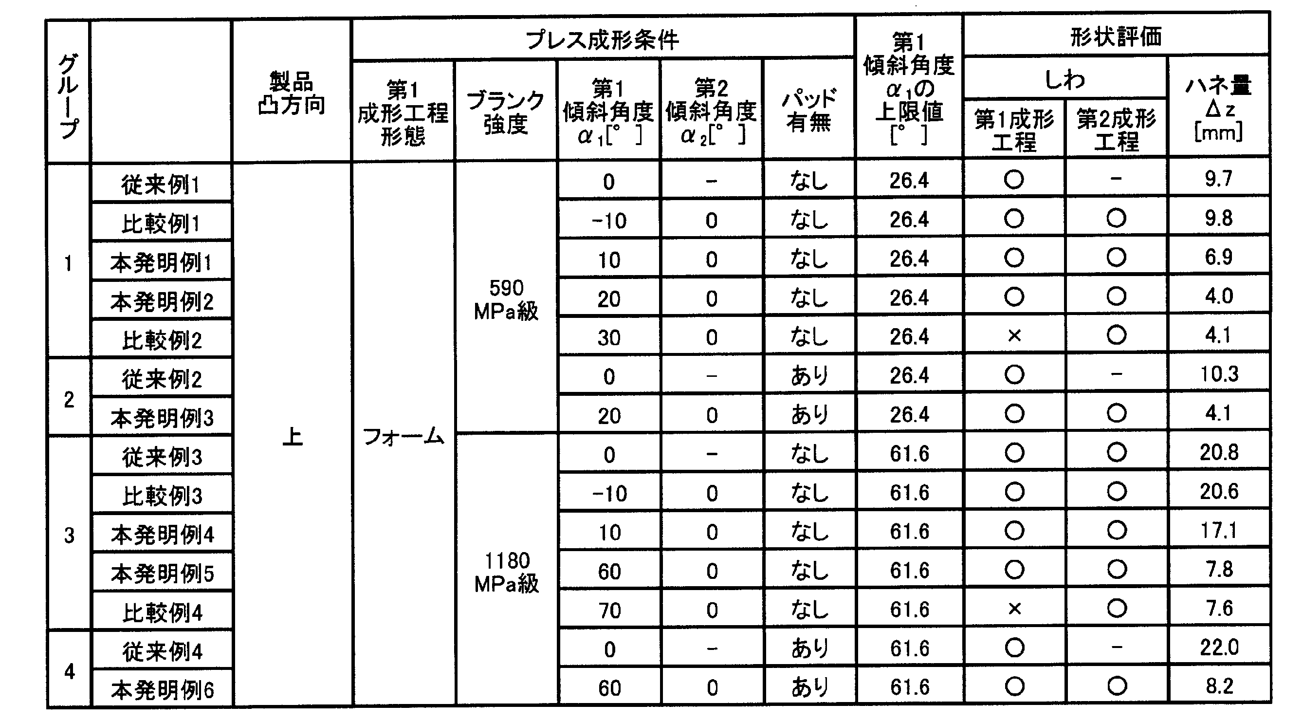
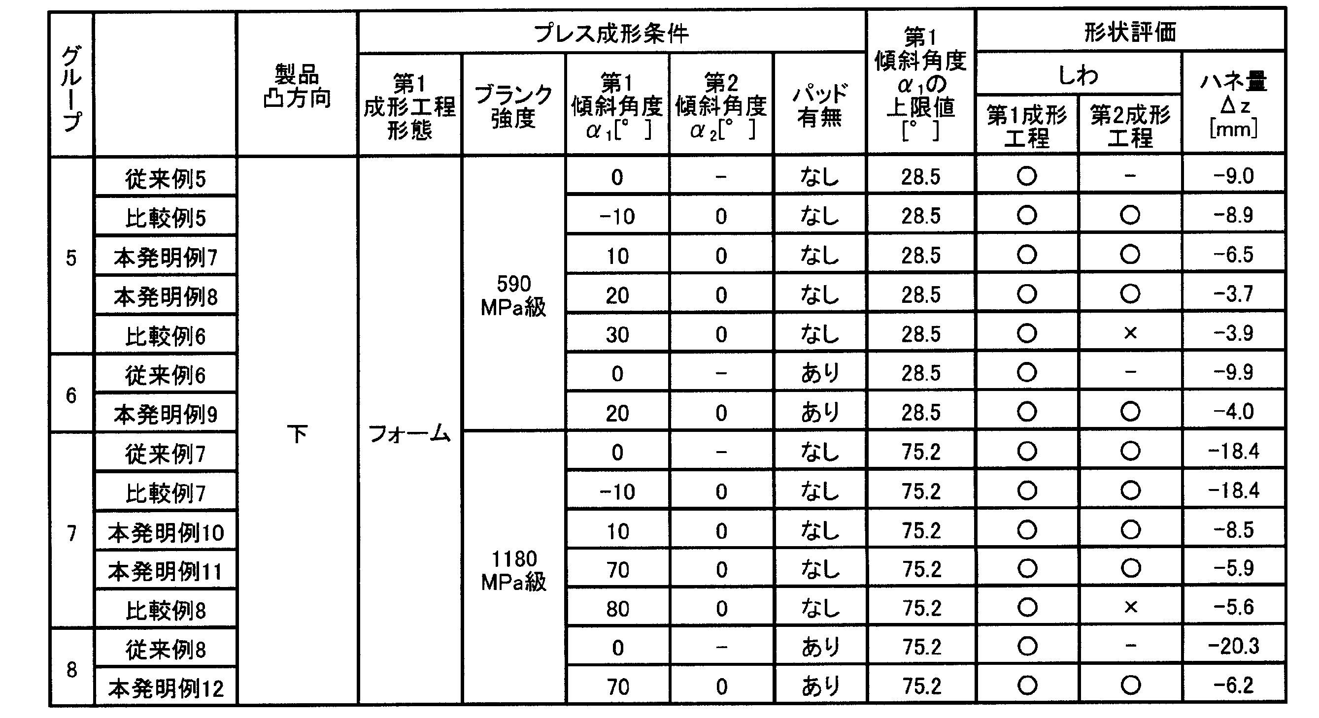
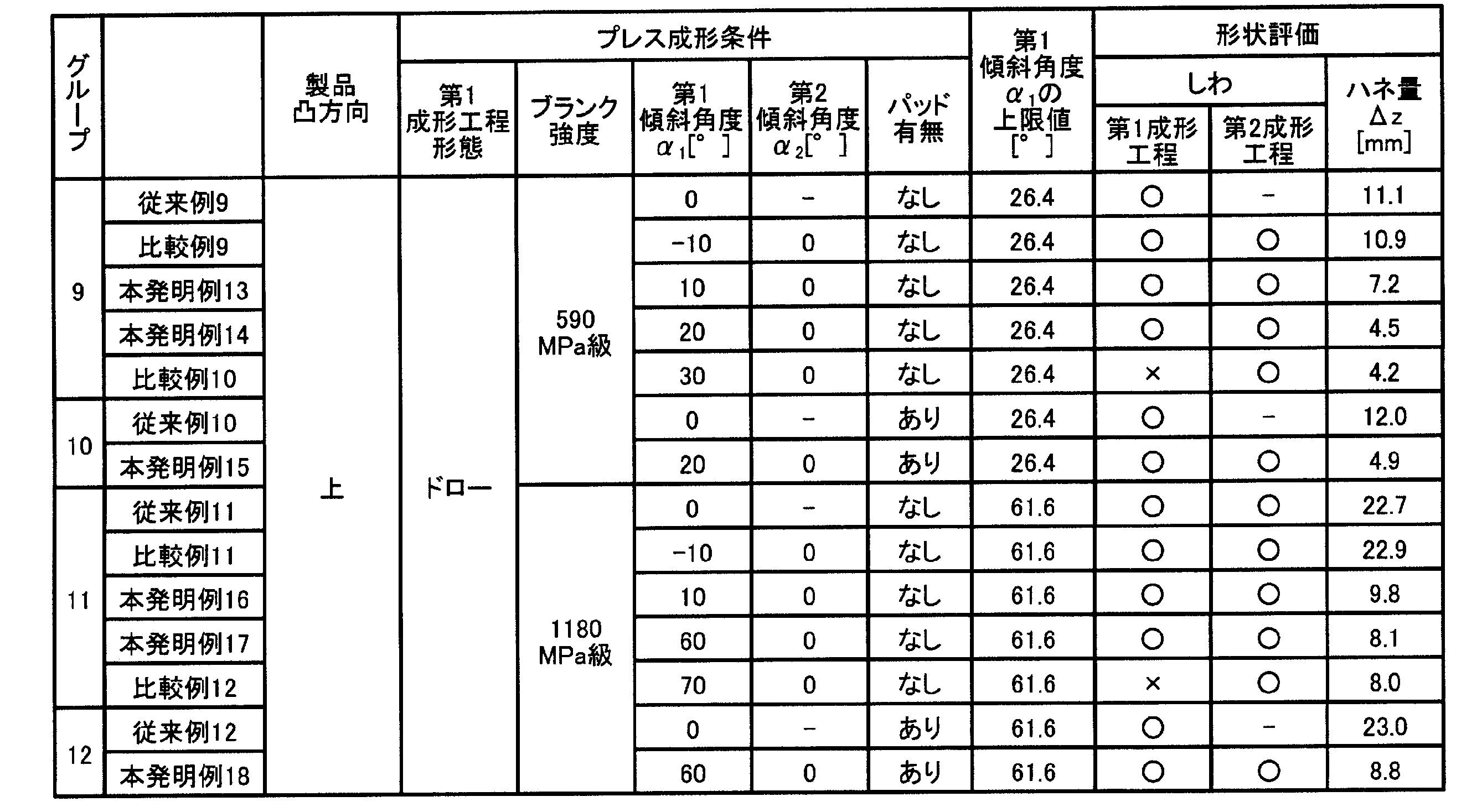


3 第2の金型(実施の形態1)
5 第1ダイ
5a 第1ダイ側の溝形状成形部
5b 第1ダイ側のフランジ成形部
7 第1パンチ
7a 第1パンチ側の溝形状成形部
7b 第1パンチ側のフランジ成形部
9 第1溝形状成形部
10 交差部
11 第1フランジ成形部
12 湾曲面
13 第2ダイ
13a 第2ダイ側の溝形状成形部
13b 第2ダイ側のフランジ成形部
15 第2パンチ
15a 第2パンチ側の溝形状成形部
15b 第2パンチ側のフランジ成形部
17 第2溝形状成形部
18 交差部
19 第2フランジ成形部
20 湾曲面
21 ブランク
23 第1の金型(実施の形態2)
25 第1ダイ
25a 第1ダイ側の溝形状成形部
25b 第1ダイ側のフランジ成形部
27 第1パンチ
27a 第1パンチ側の溝形状成形部
27b 第1パンチ側のフランジ成形部
29 第2の金型(実施の形態2)
31 第2ダイ
31a 第2ダイ側の溝形状成形部
31b 第2ダイ側のフランジ成形部
33 第2パンチ
33a 第2パンチ側の溝形状成形部
33b 第2パンチ側のフランジ成形部
35 第1の金型(実施の形態3)
37 第1ダイ
39 パッド
41 成形品(フランジ幅の異なるもの)
43 第1の金型(実施の形態4)
45 第1ダイ
47 第1パンチ
49 第1の金型(実施の形態5)
51 ダイ
53 パンチ
55 ブランクホルダ
61 成形品(フランジ部のみ上凸)
63 成形品(フランジ部のみ下凸)
75 第1の金型(実施例3)
77 第1ダイ
79 プレス金型(実施例3、従来例)
81 ダイ
83 パンチ
85 ブランクホルダ
87 第1の金型(実施例4)
89 ダイ
91 パンチ
93 ブランクホルダ
95 プレス金型(実施例4、従来例)
97 ダイ
99 パンチ
101 ブランクホルダ
103 成形品(フランジ部が傾斜しているもの)
105 第1の金型(実施例7)
107 ダイ
109 パンチ
111 ブランクホルダ
121 上凸成形品
123 溝形状部
123a 溝底部
123b 縦壁部
125 フランジ部
127 下凸成形品
141 プレス金型(従来例その1)
143 ダイ
145 パンチ
147 プレス金型(従来例その2)
149 ダイ
151 パンチ
Claims (13)
- 溝形状部を有し、該溝形状部を形成する一対の縦壁部の少なくとも一方の縦壁部に、前記溝形状部における溝底部側に凸となるように湾曲するフランジ部を有する成形品を成形するプレス成形方法であって、
前記溝形状部を成形する第1溝形状成形部と前記フランジ部を成形する第1フランジ成形部を有する第1の金型を用いて第1成形工程を行い、傾斜角度が前記第1溝形状成形部と同じ第2溝形状成形部と第2フランジ成形部を有する第2の金型を用いて第2成形工程を行うものであって、
前記第1の金型の前記第1溝形状成形部における縦壁成形部と前記第1フランジ成形部の交差部を通り該交差部における前記フランジ部の曲率と同一曲率を有する湾曲面と前記第1フランジ成形部の成す角度α1と、前記第2の金型の前記第2溝形状成形部における前記縦壁成形部と前記第2フランジ成形部の交差部を通り該交差部における前記フランジ部の曲率と同一曲率を有する湾曲面と前記第2フランジ成形部の成す角度α2との関係が、前記湾曲面を基準として該湾曲面から前記溝底部側を負、その反対側を正としたときに、α2<α1に設定されており、
前記第1成形工程にて生じた前記フランジ部の長手方向の線長を縮める圧縮ひずみを、前記第2成形工程において前記線長を伸ばす変形を与えることで戻すように成形することを特徴とするプレス成形方法。 - 前記第2の金型の前記第2溝形状成形部における前記縦壁成形部と前記第2フランジ成形部の交差部の曲率半径をρ0[mm]、前記第2成形工程で成形されるフランジ幅をL[mm]、スプリングバックを変化させる効果が得られ、且つしわを抑制できるひずみの戻し量Δε(Δε>0)の上限値をΔεmaxとすると、前記α1と前記α2が下式(1)を満たすことを特徴とする請求項1記載のプレス成形方法。

- 溝形状部を有し、該溝形状部を形成する一対の縦壁部の少なくとも一方の縦壁部に、前記溝形状部における溝底部側に凹となるように湾曲するフランジ部を有する成形品を成形するプレス成形方法であって、
前記溝形状部を成形する第1溝形状成形部と前記フランジ部を成形する第1フランジ成形部を有する第1の金型を用いて第1成形工程を行い、傾斜角度が前記第1溝形状成形部と同じ第2溝形状成形部と第2フランジ成形部を有する第2の金型を用いて第2成形工程を行うものであって、
前記第1の金型の前記第1溝形状成形部における縦壁成形部と前記第1フランジ成形部の交差部を通り該交差部における前記フランジ部の曲率と同一曲率を有する湾曲面と前記第1フランジ成形部の成す角度α1と、前記第2の金型の前記第2溝形状成形部における前記縦壁成形部と前記第2フランジ成形部の交差部を通り該交差部における前記フランジ部の曲率と同一曲率を有する湾曲面と前記第2フランジ成形部の成す角度α2との関係が、前記湾曲面を基準として該湾曲面から前記溝底部側を負、その反対側を正としたときに、α2<α1に設定されており、
前記第1成形工程にて生じた前記フランジ部の長手方向の線長を伸ばす引張りひずみを、前記第2成形工程において前記線長を縮める変形を与えることで戻すように成形することを特徴とするプレス成形方法。 - 前記第2の金型の前記第2溝形状成形部における前記縦壁成形部と前記第2フランジ成形部の交差部の曲率半径をρ0[mm]、前記第2成形工程で成形されるフランジ幅をL[mm]、スプリングバックを変化させる効果が得られ、且つしわを抑制できるひずみの戻し量Δε(Δε>0)の上限値をΔεmaxとすると、前記α1と前記α2が下式(2)を満たすことを特徴とする請求項3記載のプレス成形方法。

- 前記第1成形工程をフォーム成形で行うことを特徴とする請求項1乃至4のいずれか一項に記載のプレス成形方法。
- 前記第1成形工程をドロー成形で行うことを特徴とする請求項1乃至4のいずれか一項に記載のプレス成形方法。
- 前記溝形状部における溝底部にパンチ底部を有する成形品を成形する場合であって、前記第1成形工程はブランクにおける前記パンチ底部に相当する部位をパッドで押えてプレス成形を行うことを特徴とする請求項1乃至6のいずれか一項に記載のプレス成形方法。
- 前記一対の縦壁部のいずれか一方のフランジ部に前記第1成形工程と前記第2成形工程を適用することを特徴とする請求項1乃至7のいずれか一項に記載のプレス成形方法。
- 前記一対の縦壁部の両方のフランジ部に前記第1成形工程と前記第2成形工程を適用することを特徴とする請求項1乃至7のいずれか一項に記載のプレス成形方法。
- 湾曲する前記フランジ部が前記成形品の軸方向全長に亘って設けられている場合であって、
前記第1の金型と前記第2の金型における前記α1と前記α2の関係が、前記第1の金型と前記第2の金型における金型軸方向の一部においてα2<α1に設定されていることを特徴とする請求項1乃至9のいずれか一項に記載のプレス成形方法。 - 湾曲する前記フランジ部が前記成形品の軸方向全長に亘って設けられている場合であって、
前記第1の金型と前記第2の金型における前記α1と前記α2の関係が、前記第1の金型と前記第2の金型の全長に亘ってα2<α1に設定されていることを特徴とする請求項1乃至9のいずれか一項に記載のプレス成形方法。 - 湾曲する前記フランジ部が前記成形品の軸方向の一部に設けられている場合であって、
前記第1の金型と前記第2の金型における前記α1と前記α2の関係が、前記第1の金型と前記第2の金型における湾曲する前記フランジ部を成形する部位のみにα2<α1に設定されていることを特徴とする請求項1乃至9のいずれか一項に記載のプレス成形方法。 - 湾曲する前記フランジ部が前記成形品の軸方向の一部に設けられている場合であって、
前記第1の金型と前記第2の金型における前記α1と前記α2の関係が、前記第1の金型と前記第2の金型の全長に亘ってα2<α1に設定されていることを特徴とする請求項1乃至9のいずれか一項に記載のプレス成形方法。
Priority Applications (3)
| Application Number | Priority Date | Filing Date | Title |
|---|---|---|---|
| MX2017001212A MX2017001212A (es) | 2014-07-30 | 2015-05-11 | Metodo para la formacion de prensa. |
| CN201580041462.0A CN106660098B (zh) | 2014-07-30 | 2015-05-11 | 冲压成形方法 |
| KR1020177002106A KR101914980B1 (ko) | 2014-07-30 | 2015-05-11 | 프레스 성형 방법 |
Applications Claiming Priority (2)
| Application Number | Priority Date | Filing Date | Title |
|---|---|---|---|
| JP2014155161A JP5861749B1 (ja) | 2014-07-30 | 2014-07-30 | プレス成形方法 |
| JP2014-155161 | 2014-07-30 |
Publications (1)
| Publication Number | Publication Date |
|---|---|
| WO2016017228A1 true WO2016017228A1 (ja) | 2016-02-04 |
Family
ID=55217132
Family Applications (1)
| Application Number | Title | Priority Date | Filing Date |
|---|---|---|---|
| PCT/JP2015/063519 Ceased WO2016017228A1 (ja) | 2014-07-30 | 2015-05-11 | プレス成形(press forming)方法 |
Country Status (5)
| Country | Link |
|---|---|
| JP (1) | JP5861749B1 (ja) |
| KR (1) | KR101914980B1 (ja) |
| CN (1) | CN106660098B (ja) |
| MX (1) | MX2017001212A (ja) |
| WO (1) | WO2016017228A1 (ja) |
Cited By (4)
| Publication number | Priority date | Publication date | Assignee | Title |
|---|---|---|---|---|
| JP2019072727A (ja) * | 2017-10-13 | 2019-05-16 | Jfeスチール株式会社 | プレス成形装置及び方法 |
| JP2019076936A (ja) * | 2017-10-26 | 2019-05-23 | Jfeスチール株式会社 | プレス成形装置及び方法 |
| WO2023020950A1 (de) * | 2021-08-20 | 2023-02-23 | Thyssenkrupp Steel Europe Ag | Verfahren zur herstellung von blechbauteilen und vorrichtung hierfür |
| US20230173566A1 (en) * | 2020-05-23 | 2023-06-08 | Jfe Steel Corporation | Press forming method |
Families Citing this family (10)
| Publication number | Priority date | Publication date | Assignee | Title |
|---|---|---|---|---|
| US10213819B2 (en) * | 2015-02-27 | 2019-02-26 | Sango Co., Ltd. | Press forming method |
| EP3778057A4 (en) * | 2018-03-28 | 2021-05-19 | JFE Steel Corporation | STIFFNESS IMPROVEMENT METHODS FOR PRESS FORMED ARTICLES, PRESS FORM DIE, PRESS FORMED ARTICLES AND MANUFACTURING METHODS FOR PRESSED FORM ARTICLES |
| JP6841271B2 (ja) * | 2018-08-21 | 2021-03-10 | Jfeスチール株式会社 | プレス成形方法 |
| JP6870672B2 (ja) * | 2018-11-06 | 2021-05-12 | Jfeスチール株式会社 | プレス成形方法 |
| JP7173847B2 (ja) * | 2018-11-30 | 2022-11-16 | ダイハツ工業株式会社 | プレス成形方法 |
| JP6677289B1 (ja) * | 2018-12-12 | 2020-04-08 | Jfeスチール株式会社 | プレス成形方法 |
| JP7243657B2 (ja) * | 2020-02-14 | 2023-03-22 | Jfeスチール株式会社 | プレス成形品の形状変化予測方法 |
| JP7476935B2 (ja) * | 2022-09-28 | 2024-05-01 | Jfeスチール株式会社 | プレス成形品の製造方法 |
| JP7679921B1 (ja) * | 2023-12-14 | 2025-05-20 | Jfeスチール株式会社 | プレス成形品の製造方法 |
| WO2025126590A1 (ja) * | 2023-12-14 | 2025-06-19 | Jfeスチール株式会社 | プレス成形品の製造方法 |
Citations (6)
| Publication number | Priority date | Publication date | Assignee | Title |
|---|---|---|---|---|
| JP2004195535A (ja) * | 2002-12-20 | 2004-07-15 | Press Kogyo Co Ltd | 折り曲げ品のねじれ防止方法及び角度出し方法並びにそれらに用いるプレス装置 |
| JP4090028B2 (ja) * | 2002-11-26 | 2008-05-28 | 日新製鋼株式会社 | 薄鋼板のプレス成形用金型装置 |
| JP2010099700A (ja) * | 2008-10-23 | 2010-05-06 | Jfe Steel Corp | プレス成形用の金型、プレス成形方法、及びハット型形状の成形品 |
| JP2011206789A (ja) * | 2010-03-29 | 2011-10-20 | Kobe Steel Ltd | プレス成形方法 |
| JP2013169578A (ja) * | 2012-02-22 | 2013-09-02 | Topre Corp | プレス部品の成形方法 |
| JP5382281B1 (ja) * | 2013-01-16 | 2014-01-08 | 新日鐵住金株式会社 | プレス成形方法 |
Family Cites Families (5)
| Publication number | Priority date | Publication date | Assignee | Title |
|---|---|---|---|---|
| JPS5382281A (en) | 1976-12-28 | 1978-07-20 | Nippon Telegr & Teleph Corp <Ntt> | Production of high liminance semiconductor device and its apparatus |
| JP3376130B2 (ja) * | 1994-10-12 | 2003-02-10 | キヤノン株式会社 | ズームレンズ |
| KR101030207B1 (ko) * | 2006-03-16 | 2011-04-22 | 제이에프이 스틸 가부시키가이샤 | 냉연 강판 및 그 제조 방법, 전지 및 그 제조 방법 |
| CN201618800U (zh) * | 2010-01-27 | 2010-11-03 | 湖南铁道职业技术学院 | 一种u形自承位弯曲回弹角度可调节模具 |
| JP5327106B2 (ja) * | 2010-03-09 | 2013-10-30 | Jfeスチール株式会社 | プレス部材およびその製造方法 |
-
2014
- 2014-07-30 JP JP2014155161A patent/JP5861749B1/ja active Active
-
2015
- 2015-05-11 WO PCT/JP2015/063519 patent/WO2016017228A1/ja not_active Ceased
- 2015-05-11 KR KR1020177002106A patent/KR101914980B1/ko active Active
- 2015-05-11 CN CN201580041462.0A patent/CN106660098B/zh active Active
- 2015-05-11 MX MX2017001212A patent/MX2017001212A/es active IP Right Grant
Patent Citations (6)
| Publication number | Priority date | Publication date | Assignee | Title |
|---|---|---|---|---|
| JP4090028B2 (ja) * | 2002-11-26 | 2008-05-28 | 日新製鋼株式会社 | 薄鋼板のプレス成形用金型装置 |
| JP2004195535A (ja) * | 2002-12-20 | 2004-07-15 | Press Kogyo Co Ltd | 折り曲げ品のねじれ防止方法及び角度出し方法並びにそれらに用いるプレス装置 |
| JP2010099700A (ja) * | 2008-10-23 | 2010-05-06 | Jfe Steel Corp | プレス成形用の金型、プレス成形方法、及びハット型形状の成形品 |
| JP2011206789A (ja) * | 2010-03-29 | 2011-10-20 | Kobe Steel Ltd | プレス成形方法 |
| JP2013169578A (ja) * | 2012-02-22 | 2013-09-02 | Topre Corp | プレス部品の成形方法 |
| JP5382281B1 (ja) * | 2013-01-16 | 2014-01-08 | 新日鐵住金株式会社 | プレス成形方法 |
Cited By (5)
| Publication number | Priority date | Publication date | Assignee | Title |
|---|---|---|---|---|
| JP2019072727A (ja) * | 2017-10-13 | 2019-05-16 | Jfeスチール株式会社 | プレス成形装置及び方法 |
| JP2019076936A (ja) * | 2017-10-26 | 2019-05-23 | Jfeスチール株式会社 | プレス成形装置及び方法 |
| US20230173566A1 (en) * | 2020-05-23 | 2023-06-08 | Jfe Steel Corporation | Press forming method |
| US12233445B2 (en) * | 2020-05-23 | 2025-02-25 | Jfe Steel Corporation | Press forming method |
| WO2023020950A1 (de) * | 2021-08-20 | 2023-02-23 | Thyssenkrupp Steel Europe Ag | Verfahren zur herstellung von blechbauteilen und vorrichtung hierfür |
Also Published As
| Publication number | Publication date |
|---|---|
| JP2016030290A (ja) | 2016-03-07 |
| KR20170021867A (ko) | 2017-02-28 |
| MX2017001212A (es) | 2017-04-27 |
| CN106660098A (zh) | 2017-05-10 |
| JP5861749B1 (ja) | 2016-02-16 |
| KR101914980B1 (ko) | 2018-11-05 |
| CN106660098B (zh) | 2018-09-21 |
Similar Documents
| Publication | Publication Date | Title |
|---|---|---|
| JP5861749B1 (ja) | プレス成形方法 | |
| JP5382281B1 (ja) | プレス成形方法 | |
| CN105358269B (zh) | 冲压成形方法及冲压成形装置 | |
| CN112584944B (zh) | 压制成型方法 | |
| JP4920649B2 (ja) | 形状凍結性に優れる多段プレス成形方法 | |
| JP5987934B2 (ja) | プレス成形方法、プレス成形金型 | |
| CN109562427B (zh) | 冲压成型品的制造方法 | |
| JP6512191B2 (ja) | 金型の設計方法およびプレス成形品の製造方法 | |
| CN107530752A (zh) | 冲压成型件的制造方法、冲压成型件以及冲压装置 | |
| KR101867744B1 (ko) | 프레스 성형 방법 및 프레스 제품의 제조 방법 그리고 프레스 성형 장치 | |
| WO2021240941A1 (ja) | プレス成形方法 | |
| JP6083390B2 (ja) | プレス成形方法 | |
| CN107921504B (zh) | 拉伸凸缘成形零件的制造方法 | |
| KR102545162B1 (ko) | 프레스 성형 방법 | |
| US12036596B2 (en) | Press forming method | |
| JP6380294B2 (ja) | プレス成形方法 | |
| KR20180105216A (ko) | 프레스 성형품의 제조 방법 | |
| JP5031703B2 (ja) | 形状凍結性に優れる多段プレス成形方法 | |
| CN113766980B (zh) | 冲压成型方法 | |
| WO2021240942A1 (ja) | プレス成形金型及びプレス成形方法 | |
| KR20230002914A (ko) | 프레스 성형 금형 및 프레스 성형 방법 | |
| JP7448464B2 (ja) | 鋼部品の製造方法 | |
| WO2021241024A1 (ja) | プレス成形方法 |
Legal Events
| Date | Code | Title | Description |
|---|---|---|---|
| 121 | Ep: the epo has been informed by wipo that ep was designated in this application |
Ref document number: 15826801 Country of ref document: EP Kind code of ref document: A1 |
|
| ENP | Entry into the national phase |
Ref document number: 20177002106 Country of ref document: KR Kind code of ref document: A |
|
| WWE | Wipo information: entry into national phase |
Ref document number: MX/A/2017/001212 Country of ref document: MX |
|
| NENP | Non-entry into the national phase |
Ref country code: DE |
|
| 122 | Ep: pct application non-entry in european phase |
Ref document number: 15826801 Country of ref document: EP Kind code of ref document: A1 |