WO2016017014A1 - 作業車両及び作業車両の制御方法 - Google Patents
作業車両及び作業車両の制御方法 Download PDFInfo
- Publication number
- WO2016017014A1 WO2016017014A1 PCT/JP2014/070268 JP2014070268W WO2016017014A1 WO 2016017014 A1 WO2016017014 A1 WO 2016017014A1 JP 2014070268 W JP2014070268 W JP 2014070268W WO 2016017014 A1 WO2016017014 A1 WO 2016017014A1
- Authority
- WO
- WIPO (PCT)
- Prior art keywords
- driving force
- control device
- work vehicle
- engine
- vehicle speed
- Prior art date
- Legal status (The legal status is an assumption and is not a legal conclusion. Google has not performed a legal analysis and makes no representation as to the accuracy of the status listed.)
- Ceased
Links
Images






Classifications
-
- B—PERFORMING OPERATIONS; TRANSPORTING
- B60—VEHICLES IN GENERAL
- B60W—CONJOINT CONTROL OF VEHICLE SUB-UNITS OF DIFFERENT TYPE OR DIFFERENT FUNCTION; CONTROL SYSTEMS SPECIALLY ADAPTED FOR HYBRID VEHICLES; ROAD VEHICLE DRIVE CONTROL SYSTEMS FOR PURPOSES NOT RELATED TO THE CONTROL OF A PARTICULAR SUB-UNIT
- B60W30/00—Purposes of road vehicle drive control systems not related to the control of a particular sub-unit, e.g. of systems using conjoint control of vehicle sub-units
- B60W30/18—Propelling the vehicle
- B60W30/18172—Preventing, or responsive to skidding of wheels
-
- B—PERFORMING OPERATIONS; TRANSPORTING
- B60—VEHICLES IN GENERAL
- B60K—ARRANGEMENT OR MOUNTING OF PROPULSION UNITS OR OF TRANSMISSIONS IN VEHICLES; ARRANGEMENT OR MOUNTING OF PLURAL DIVERSE PRIME-MOVERS IN VEHICLES; AUXILIARY DRIVES FOR VEHICLES; INSTRUMENTATION OR DASHBOARDS FOR VEHICLES; ARRANGEMENTS IN CONNECTION WITH COOLING, AIR INTAKE, GAS EXHAUST OR FUEL SUPPLY OF PROPULSION UNITS IN VEHICLES
- B60K17/00—Arrangement or mounting of transmissions in vehicles
- B60K17/34—Arrangement or mounting of transmissions in vehicles for driving both front and rear wheels, e.g. four wheel drive vehicles
- B60K17/348—Arrangement or mounting of transmissions in vehicles for driving both front and rear wheels, e.g. four wheel drive vehicles having differential means for driving one set of wheels, e.g. the front, at one speed and the other set, e.g. the rear, at a different speed
- B60K17/35—Arrangement or mounting of transmissions in vehicles for driving both front and rear wheels, e.g. four wheel drive vehicles having differential means for driving one set of wheels, e.g. the front, at one speed and the other set, e.g. the rear, at a different speed including arrangements for suppressing or influencing the power transfer, e.g. viscous clutches
-
- B—PERFORMING OPERATIONS; TRANSPORTING
- B60—VEHICLES IN GENERAL
- B60K—ARRANGEMENT OR MOUNTING OF PROPULSION UNITS OR OF TRANSMISSIONS IN VEHICLES; ARRANGEMENT OR MOUNTING OF PLURAL DIVERSE PRIME-MOVERS IN VEHICLES; AUXILIARY DRIVES FOR VEHICLES; INSTRUMENTATION OR DASHBOARDS FOR VEHICLES; ARRANGEMENTS IN CONNECTION WITH COOLING, AIR INTAKE, GAS EXHAUST OR FUEL SUPPLY OF PROPULSION UNITS IN VEHICLES
- B60K28/00—Safety devices for propulsion-unit control, specially adapted for, or arranged in, vehicles, e.g. preventing fuel supply or ignition in the event of potentially dangerous conditions
- B60K28/10—Safety devices for propulsion-unit control, specially adapted for, or arranged in, vehicles, e.g. preventing fuel supply or ignition in the event of potentially dangerous conditions responsive to conditions relating to the vehicle
- B60K28/16—Safety devices for propulsion-unit control, specially adapted for, or arranged in, vehicles, e.g. preventing fuel supply or ignition in the event of potentially dangerous conditions responsive to conditions relating to the vehicle responsive to, or preventing, spinning or skidding of wheels
-
- B—PERFORMING OPERATIONS; TRANSPORTING
- B60—VEHICLES IN GENERAL
- B60P—VEHICLES ADAPTED FOR LOAD TRANSPORTATION OR TO TRANSPORT, TO CARRY, OR TO COMPRISE SPECIAL LOADS OR OBJECTS
- B60P3/00—Vehicles adapted to transport, to carry or to comprise special loads or objects
-
- B—PERFORMING OPERATIONS; TRANSPORTING
- B60—VEHICLES IN GENERAL
- B60T—VEHICLE BRAKE CONTROL SYSTEMS OR PARTS THEREOF; BRAKE CONTROL SYSTEMS OR PARTS THEREOF, IN GENERAL; ARRANGEMENT OF BRAKING ELEMENTS ON VEHICLES IN GENERAL; PORTABLE DEVICES FOR PREVENTING UNWANTED MOVEMENT OF VEHICLES; VEHICLE MODIFICATIONS TO FACILITATE COOLING OF BRAKES
- B60T7/00—Brake-action initiating means
- B60T7/12—Brake-action initiating means for automatic initiation; for initiation not subject to will of driver or passenger
-
- B—PERFORMING OPERATIONS; TRANSPORTING
- B60—VEHICLES IN GENERAL
- B60T—VEHICLE BRAKE CONTROL SYSTEMS OR PARTS THEREOF; BRAKE CONTROL SYSTEMS OR PARTS THEREOF, IN GENERAL; ARRANGEMENT OF BRAKING ELEMENTS ON VEHICLES IN GENERAL; PORTABLE DEVICES FOR PREVENTING UNWANTED MOVEMENT OF VEHICLES; VEHICLE MODIFICATIONS TO FACILITATE COOLING OF BRAKES
- B60T7/00—Brake-action initiating means
- B60T7/12—Brake-action initiating means for automatic initiation; for initiation not subject to will of driver or passenger
- B60T7/16—Brake-action initiating means for automatic initiation; for initiation not subject to will of driver or passenger operated by remote control, i.e. initiating means not mounted on vehicle
- B60T7/18—Brake-action initiating means for automatic initiation; for initiation not subject to will of driver or passenger operated by remote control, i.e. initiating means not mounted on vehicle operated by wayside apparatus
-
- B—PERFORMING OPERATIONS; TRANSPORTING
- B60—VEHICLES IN GENERAL
- B60T—VEHICLE BRAKE CONTROL SYSTEMS OR PARTS THEREOF; BRAKE CONTROL SYSTEMS OR PARTS THEREOF, IN GENERAL; ARRANGEMENT OF BRAKING ELEMENTS ON VEHICLES IN GENERAL; PORTABLE DEVICES FOR PREVENTING UNWANTED MOVEMENT OF VEHICLES; VEHICLE MODIFICATIONS TO FACILITATE COOLING OF BRAKES
- B60T8/00—Arrangements for adjusting wheel-braking force to meet varying vehicular or ground-surface conditions, e.g. limiting or varying distribution of braking force
- B60T8/17—Using electrical or electronic regulation means to control braking
- B60T8/174—Using electrical or electronic regulation means to control braking characterised by using special control logic, e.g. fuzzy logic, neural computing
-
- B—PERFORMING OPERATIONS; TRANSPORTING
- B60—VEHICLES IN GENERAL
- B60T—VEHICLE BRAKE CONTROL SYSTEMS OR PARTS THEREOF; BRAKE CONTROL SYSTEMS OR PARTS THEREOF, IN GENERAL; ARRANGEMENT OF BRAKING ELEMENTS ON VEHICLES IN GENERAL; PORTABLE DEVICES FOR PREVENTING UNWANTED MOVEMENT OF VEHICLES; VEHICLE MODIFICATIONS TO FACILITATE COOLING OF BRAKES
- B60T8/00—Arrangements for adjusting wheel-braking force to meet varying vehicular or ground-surface conditions, e.g. limiting or varying distribution of braking force
- B60T8/17—Using electrical or electronic regulation means to control braking
- B60T8/175—Brake regulation specially adapted to prevent excessive wheel spin during vehicle acceleration, e.g. for traction control
-
- B—PERFORMING OPERATIONS; TRANSPORTING
- B60—VEHICLES IN GENERAL
- B60W—CONJOINT CONTROL OF VEHICLE SUB-UNITS OF DIFFERENT TYPE OR DIFFERENT FUNCTION; CONTROL SYSTEMS SPECIALLY ADAPTED FOR HYBRID VEHICLES; ROAD VEHICLE DRIVE CONTROL SYSTEMS FOR PURPOSES NOT RELATED TO THE CONTROL OF A PARTICULAR SUB-UNIT
- B60W10/00—Conjoint control of vehicle sub-units of different type or different function
- B60W10/04—Conjoint control of vehicle sub-units of different type or different function including control of propulsion units
- B60W10/06—Conjoint control of vehicle sub-units of different type or different function including control of propulsion units including control of combustion engines
-
- B—PERFORMING OPERATIONS; TRANSPORTING
- B60—VEHICLES IN GENERAL
- B60W—CONJOINT CONTROL OF VEHICLE SUB-UNITS OF DIFFERENT TYPE OR DIFFERENT FUNCTION; CONTROL SYSTEMS SPECIALLY ADAPTED FOR HYBRID VEHICLES; ROAD VEHICLE DRIVE CONTROL SYSTEMS FOR PURPOSES NOT RELATED TO THE CONTROL OF A PARTICULAR SUB-UNIT
- B60W10/00—Conjoint control of vehicle sub-units of different type or different function
- B60W10/18—Conjoint control of vehicle sub-units of different type or different function including control of braking systems
-
- B—PERFORMING OPERATIONS; TRANSPORTING
- B60—VEHICLES IN GENERAL
- B60W—CONJOINT CONTROL OF VEHICLE SUB-UNITS OF DIFFERENT TYPE OR DIFFERENT FUNCTION; CONTROL SYSTEMS SPECIALLY ADAPTED FOR HYBRID VEHICLES; ROAD VEHICLE DRIVE CONTROL SYSTEMS FOR PURPOSES NOT RELATED TO THE CONTROL OF A PARTICULAR SUB-UNIT
- B60W30/00—Purposes of road vehicle drive control systems not related to the control of a particular sub-unit, e.g. of systems using conjoint control of vehicle sub-units
-
- B—PERFORMING OPERATIONS; TRANSPORTING
- B60—VEHICLES IN GENERAL
- B60W—CONJOINT CONTROL OF VEHICLE SUB-UNITS OF DIFFERENT TYPE OR DIFFERENT FUNCTION; CONTROL SYSTEMS SPECIALLY ADAPTED FOR HYBRID VEHICLES; ROAD VEHICLE DRIVE CONTROL SYSTEMS FOR PURPOSES NOT RELATED TO THE CONTROL OF A PARTICULAR SUB-UNIT
- B60W30/00—Purposes of road vehicle drive control systems not related to the control of a particular sub-unit, e.g. of systems using conjoint control of vehicle sub-units
- B60W30/02—Control of vehicle driving stability
-
- B—PERFORMING OPERATIONS; TRANSPORTING
- B60—VEHICLES IN GENERAL
- B60W—CONJOINT CONTROL OF VEHICLE SUB-UNITS OF DIFFERENT TYPE OR DIFFERENT FUNCTION; CONTROL SYSTEMS SPECIALLY ADAPTED FOR HYBRID VEHICLES; ROAD VEHICLE DRIVE CONTROL SYSTEMS FOR PURPOSES NOT RELATED TO THE CONTROL OF A PARTICULAR SUB-UNIT
- B60W30/00—Purposes of road vehicle drive control systems not related to the control of a particular sub-unit, e.g. of systems using conjoint control of vehicle sub-units
- B60W30/18—Propelling the vehicle
- B60W30/188—Controlling power parameters of the driveline, e.g. determining the required power
-
- G—PHYSICS
- G01—MEASURING; TESTING
- G01S—RADIO DIRECTION-FINDING; RADIO NAVIGATION; DETERMINING DISTANCE OR VELOCITY BY USE OF RADIO WAVES; LOCATING OR PRESENCE-DETECTING BY USE OF THE REFLECTION OR RERADIATION OF RADIO WAVES; ANALOGOUS ARRANGEMENTS USING OTHER WAVES
- G01S13/00—Systems using the reflection or reradiation of radio waves, e.g. radar systems; Analogous systems using reflection or reradiation of waves whose nature or wavelength is irrelevant or unspecified
- G01S13/88—Radar or analogous systems specially adapted for specific applications
- G01S13/93—Radar or analogous systems specially adapted for specific applications for anti-collision purposes
- G01S13/931—Radar or analogous systems specially adapted for specific applications for anti-collision purposes of land vehicles
-
- G—PHYSICS
- G08—SIGNALLING
- G08G—TRAFFIC CONTROL SYSTEMS
- G08G1/00—Traffic control systems for road vehicles
- G08G1/09—Arrangements for giving variable traffic instructions
- G08G1/0962—Arrangements for giving variable traffic instructions having an indicator mounted inside the vehicle, e.g. giving voice messages
- G08G1/0967—Systems involving transmission of highway information, e.g. weather, speed limits
- G08G1/096708—Systems involving transmission of highway information, e.g. weather, speed limits where the received information might be used to generate an automatic action on the vehicle control
- G08G1/096725—Systems involving transmission of highway information, e.g. weather, speed limits where the received information might be used to generate an automatic action on the vehicle control where the received information generates an automatic action on the vehicle control
-
- G—PHYSICS
- G08—SIGNALLING
- G08G—TRAFFIC CONTROL SYSTEMS
- G08G1/00—Traffic control systems for road vehicles
- G08G1/09—Arrangements for giving variable traffic instructions
- G08G1/0962—Arrangements for giving variable traffic instructions having an indicator mounted inside the vehicle, e.g. giving voice messages
- G08G1/0967—Systems involving transmission of highway information, e.g. weather, speed limits
- G08G1/096733—Systems involving transmission of highway information, e.g. weather, speed limits where a selection of the information might take place
- G08G1/096741—Systems involving transmission of highway information, e.g. weather, speed limits where a selection of the information might take place where the source of the transmitted information selects which information to transmit to each vehicle
-
- G—PHYSICS
- G08—SIGNALLING
- G08G—TRAFFIC CONTROL SYSTEMS
- G08G1/00—Traffic control systems for road vehicles
- G08G1/09—Arrangements for giving variable traffic instructions
- G08G1/0962—Arrangements for giving variable traffic instructions having an indicator mounted inside the vehicle, e.g. giving voice messages
- G08G1/0967—Systems involving transmission of highway information, e.g. weather, speed limits
- G08G1/096766—Systems involving transmission of highway information, e.g. weather, speed limits where the system is characterised by the origin of the information transmission
- G08G1/096775—Systems involving transmission of highway information, e.g. weather, speed limits where the system is characterised by the origin of the information transmission where the origin of the information is a central station
-
- G—PHYSICS
- G08—SIGNALLING
- G08G—TRAFFIC CONTROL SYSTEMS
- G08G1/00—Traffic control systems for road vehicles
- G08G1/16—Anti-collision systems
-
- G—PHYSICS
- G08—SIGNALLING
- G08G—TRAFFIC CONTROL SYSTEMS
- G08G1/00—Traffic control systems for road vehicles
- G08G1/16—Anti-collision systems
- G08G1/165—Anti-collision systems for passive traffic, e.g. including static obstacles, trees
-
- G—PHYSICS
- G08—SIGNALLING
- G08G—TRAFFIC CONTROL SYSTEMS
- G08G1/00—Traffic control systems for road vehicles
- G08G1/16—Anti-collision systems
- G08G1/166—Anti-collision systems for active traffic, e.g. moving vehicles, pedestrians, bikes
-
- G—PHYSICS
- G08—SIGNALLING
- G08G—TRAFFIC CONTROL SYSTEMS
- G08G1/00—Traffic control systems for road vehicles
- G08G1/20—Monitoring the location of vehicles belonging to a group, e.g. fleet of vehicles, countable or determined number of vehicles
-
- B—PERFORMING OPERATIONS; TRANSPORTING
- B60—VEHICLES IN GENERAL
- B60W—CONJOINT CONTROL OF VEHICLE SUB-UNITS OF DIFFERENT TYPE OR DIFFERENT FUNCTION; CONTROL SYSTEMS SPECIALLY ADAPTED FOR HYBRID VEHICLES; ROAD VEHICLE DRIVE CONTROL SYSTEMS FOR PURPOSES NOT RELATED TO THE CONTROL OF A PARTICULAR SUB-UNIT
- B60W2300/00—Indexing codes relating to the type of vehicle
- B60W2300/12—Trucks; Load vehicles
- B60W2300/125—Heavy duty trucks
-
- B—PERFORMING OPERATIONS; TRANSPORTING
- B60—VEHICLES IN GENERAL
- B60W—CONJOINT CONTROL OF VEHICLE SUB-UNITS OF DIFFERENT TYPE OR DIFFERENT FUNCTION; CONTROL SYSTEMS SPECIALLY ADAPTED FOR HYBRID VEHICLES; ROAD VEHICLE DRIVE CONTROL SYSTEMS FOR PURPOSES NOT RELATED TO THE CONTROL OF A PARTICULAR SUB-UNIT
- B60W2300/00—Indexing codes relating to the type of vehicle
- B60W2300/17—Construction vehicles, e.g. graders, excavators
-
- B—PERFORMING OPERATIONS; TRANSPORTING
- B60—VEHICLES IN GENERAL
- B60W—CONJOINT CONTROL OF VEHICLE SUB-UNITS OF DIFFERENT TYPE OR DIFFERENT FUNCTION; CONTROL SYSTEMS SPECIALLY ADAPTED FOR HYBRID VEHICLES; ROAD VEHICLE DRIVE CONTROL SYSTEMS FOR PURPOSES NOT RELATED TO THE CONTROL OF A PARTICULAR SUB-UNIT
- B60W2520/00—Input parameters relating to overall vehicle dynamics
- B60W2520/10—Longitudinal speed
-
- B—PERFORMING OPERATIONS; TRANSPORTING
- B60—VEHICLES IN GENERAL
- B60W—CONJOINT CONTROL OF VEHICLE SUB-UNITS OF DIFFERENT TYPE OR DIFFERENT FUNCTION; CONTROL SYSTEMS SPECIALLY ADAPTED FOR HYBRID VEHICLES; ROAD VEHICLE DRIVE CONTROL SYSTEMS FOR PURPOSES NOT RELATED TO THE CONTROL OF A PARTICULAR SUB-UNIT
- B60W2520/00—Input parameters relating to overall vehicle dynamics
- B60W2520/26—Wheel slip
-
- B—PERFORMING OPERATIONS; TRANSPORTING
- B60—VEHICLES IN GENERAL
- B60W—CONJOINT CONTROL OF VEHICLE SUB-UNITS OF DIFFERENT TYPE OR DIFFERENT FUNCTION; CONTROL SYSTEMS SPECIALLY ADAPTED FOR HYBRID VEHICLES; ROAD VEHICLE DRIVE CONTROL SYSTEMS FOR PURPOSES NOT RELATED TO THE CONTROL OF A PARTICULAR SUB-UNIT
- B60W2520/00—Input parameters relating to overall vehicle dynamics
- B60W2520/26—Wheel slip
- B60W2520/263—Slip values between front and rear axle
-
- B—PERFORMING OPERATIONS; TRANSPORTING
- B60—VEHICLES IN GENERAL
- B60W—CONJOINT CONTROL OF VEHICLE SUB-UNITS OF DIFFERENT TYPE OR DIFFERENT FUNCTION; CONTROL SYSTEMS SPECIALLY ADAPTED FOR HYBRID VEHICLES; ROAD VEHICLE DRIVE CONTROL SYSTEMS FOR PURPOSES NOT RELATED TO THE CONTROL OF A PARTICULAR SUB-UNIT
- B60W2520/00—Input parameters relating to overall vehicle dynamics
- B60W2520/28—Wheel speed
-
- B—PERFORMING OPERATIONS; TRANSPORTING
- B60—VEHICLES IN GENERAL
- B60W—CONJOINT CONTROL OF VEHICLE SUB-UNITS OF DIFFERENT TYPE OR DIFFERENT FUNCTION; CONTROL SYSTEMS SPECIALLY ADAPTED FOR HYBRID VEHICLES; ROAD VEHICLE DRIVE CONTROL SYSTEMS FOR PURPOSES NOT RELATED TO THE CONTROL OF A PARTICULAR SUB-UNIT
- B60W2556/00—Input parameters relating to data
- B60W2556/45—External transmission of data to or from the vehicle
-
- B—PERFORMING OPERATIONS; TRANSPORTING
- B60—VEHICLES IN GENERAL
- B60W—CONJOINT CONTROL OF VEHICLE SUB-UNITS OF DIFFERENT TYPE OR DIFFERENT FUNCTION; CONTROL SYSTEMS SPECIALLY ADAPTED FOR HYBRID VEHICLES; ROAD VEHICLE DRIVE CONTROL SYSTEMS FOR PURPOSES NOT RELATED TO THE CONTROL OF A PARTICULAR SUB-UNIT
- B60W2710/00—Output or target parameters relating to a particular sub-units
- B60W2710/06—Combustion engines, Gas turbines
-
- B—PERFORMING OPERATIONS; TRANSPORTING
- B60—VEHICLES IN GENERAL
- B60W—CONJOINT CONTROL OF VEHICLE SUB-UNITS OF DIFFERENT TYPE OR DIFFERENT FUNCTION; CONTROL SYSTEMS SPECIALLY ADAPTED FOR HYBRID VEHICLES; ROAD VEHICLE DRIVE CONTROL SYSTEMS FOR PURPOSES NOT RELATED TO THE CONTROL OF A PARTICULAR SUB-UNIT
- B60W2710/00—Output or target parameters relating to a particular sub-units
- B60W2710/06—Combustion engines, Gas turbines
- B60W2710/0666—Engine torque
-
- B—PERFORMING OPERATIONS; TRANSPORTING
- B60—VEHICLES IN GENERAL
- B60W—CONJOINT CONTROL OF VEHICLE SUB-UNITS OF DIFFERENT TYPE OR DIFFERENT FUNCTION; CONTROL SYSTEMS SPECIALLY ADAPTED FOR HYBRID VEHICLES; ROAD VEHICLE DRIVE CONTROL SYSTEMS FOR PURPOSES NOT RELATED TO THE CONTROL OF A PARTICULAR SUB-UNIT
- B60W2710/00—Output or target parameters relating to a particular sub-units
- B60W2710/18—Braking system
-
- B—PERFORMING OPERATIONS; TRANSPORTING
- B60—VEHICLES IN GENERAL
- B60W—CONJOINT CONTROL OF VEHICLE SUB-UNITS OF DIFFERENT TYPE OR DIFFERENT FUNCTION; CONTROL SYSTEMS SPECIALLY ADAPTED FOR HYBRID VEHICLES; ROAD VEHICLE DRIVE CONTROL SYSTEMS FOR PURPOSES NOT RELATED TO THE CONTROL OF A PARTICULAR SUB-UNIT
- B60W2710/00—Output or target parameters relating to a particular sub-units
- B60W2710/18—Braking system
- B60W2710/182—Brake pressure, e.g. of fluid or between pad and disc
-
- B—PERFORMING OPERATIONS; TRANSPORTING
- B60—VEHICLES IN GENERAL
- B60W—CONJOINT CONTROL OF VEHICLE SUB-UNITS OF DIFFERENT TYPE OR DIFFERENT FUNCTION; CONTROL SYSTEMS SPECIALLY ADAPTED FOR HYBRID VEHICLES; ROAD VEHICLE DRIVE CONTROL SYSTEMS FOR PURPOSES NOT RELATED TO THE CONTROL OF A PARTICULAR SUB-UNIT
- B60W2720/00—Output or target parameters relating to overall vehicle dynamics
- B60W2720/28—Wheel speed
Definitions
- the present invention relates to a work vehicle and a work vehicle control method.
- Patent Document 1 describes a technique for realizing traction control by reducing the driving force of driving wheels using a brake.
- the drive wheels When driving a mechanical work vehicle, the drive wheels may not recover from the slip even though the traction control using the brake is operating.
- An object of the present invention is to recover the slip of a drive wheel and continue running in a mechanical work vehicle.
- the present invention executes first driving force control for braking an engine, a plurality of driving wheels driven by the engine, and a slipping driving wheel among the plurality of driving wheels, and the first driving force control And a driving control device that executes a second driving force control that reduces the output of the engine in accordance with a slip ratio of the slipping driving wheel during the driving force control.
- the operation control device is configured such that the first driving force control is stopped during execution of the second driving force control, and the actual vehicle speed of the work vehicle is greater than a threshold value of the first vehicle speed. When it is equal to or higher than the vehicle speed threshold, it is preferable to end the second driving force control being executed.
- a communication device that communicates with the outside of the work vehicle, the operation control device acquires a target vehicle speed of the work vehicle from the communication device, and controls the actual vehicle speed of the work vehicle to be the target vehicle speed; At the time of the second driving force control, the slip rate of the slipping drive wheel is obtained from the target accelerator opening degree of the accelerator for adjusting the output of the engine, which is obtained according to the target vehicle speed and the actual vehicle speed. It is preferable to subtract the corrected accelerator opening determined accordingly.
- the present invention is a work vehicle including an engine and a plurality of drive wheels driven by the engine, a communication device that communicates with an outside of the work vehicle, and a target vehicle speed of the work vehicle is acquired from the communication device, A drive control device that controls the actual vehicle speed of the work vehicle to be a target vehicle speed, wherein the drive control device is configured to drive a slipping drive wheel among the plurality of drive wheels.
- the first driving force control for braking so that the slip ratio of the driving wheel becomes the target value of the slip ratio of the driving wheel, and during the execution of the first driving force control, the slipping driving wheel
- It is a work vehicle which performs 2nd driving force control which reduces the output of the said engine according to a slip ratio.
- the slip ratio of the plurality of driving wheels is obtained, and slipping among the plurality of driving wheels is performed.
- a control method for a work vehicle including reducing the output of the engine in accordance with a slip rate of the slipping drive wheel when a state where the speed is equal to or greater than a speed difference threshold value continues.
- the present invention can recover the slip of the drive wheel and continue running in a mechanical work vehicle.
- FIG. 1 is a diagram illustrating a site where the work vehicle according to the present embodiment operates.
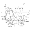
- FIG. 2 is a diagram illustrating the dump truck according to the present embodiment.
- FIG. 3 is a block diagram illustrating a control system provided in the dump truck.
- FIG. 4 is a flowchart showing a procedure for executing the work vehicle control method according to the present embodiment.
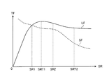
- FIG. 5A is a diagram illustrating a relationship between the slip ratio SR and the frictional force.
- FIG. 5B is a diagram illustrating a rear wheel that is a driving wheel and a road surface on which the rear wheel contacts the ground.
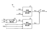
- FIG. 6 is a block diagram illustrating the output suppression calculation unit.
- FIG. 7 is a block diagram illustrating a corrected accelerator opening calculation unit.
- FIG. 8 is a flowchart showing a process when the second driving force control ends.
- FIG. 9 is a block diagram illustrating a corrected accelerator opening calculation unit.
- FIG. 10 is a diagram illustrating an example of a
- FIG. 1 is a diagram illustrating a site where a work vehicle according to the present embodiment operates.
- the work vehicle of this embodiment is used for various work in a mine, a work vehicle is not limited to what is used in a mine.
- the work vehicle is exemplified by the dump truck 10 as a transport vehicle that transports crushed stone or earth and sand generated during the excavation of crushed stone, but the work vehicle is not limited to this.
- the work vehicle according to the present embodiment may be a wheel loader or the like.
- the work vehicle may be an autonomous traveling vehicle that travels by generating a traveling route by itself.
- the dump truck 10 is managed by the unmanned dump operation system 1 and travels automatically.
- the operation management device 2 provides information necessary for automatic operation such as the destination of the dump truck 10, travel permission for each section, position information of other vehicles and emergency stop command via wireless communication. 10 to send.
- the dump truck 10 automatically travels based on information necessary for automatic driving acquired from the operation management device 2.
- the operation management device 2 is different from the dump truck 10 that is a moving body, and is a kind of management device that is installed in a mine management facility and manages the operation of the work vehicle including the dump truck 10 and the mine. .
- the operation management device 2 is connected to a wireless communication device 4 having an antenna 4A in order to run the dump truck 10 operating in the mine.
- the dump truck 10 has an antenna 17 ⁇ / b> A for receiving a command from the operation management device 2 and transmitting its own operation information to the operation management device 2.
- the dump truck 10 can receive radio waves from GPS (Global Positioning System) satellites 5A, 5B, and 5C with the GPS antenna 18A, and can determine its own position.
- GPS Global Positioning System
- the unmanned dump operation system 1 includes the repeater 3 that relays the radio waves transmitted by the antenna 4A and the antenna 17A.
- the operation management apparatus 2 can transmit a command for control to the dump truck 10 operating at a position away from itself, or collect the operation information from the dump truck 10. .
- the dump truck 10 travels on a flat road FR or travels on a slope RS when traveling between a dumping site and a loading site. Next, the dump truck 10 will be described.
- FIG. 2 is a diagram illustrating the dump truck 10 according to the present embodiment.
- the dump truck 10 is managed and automatically operated by the unmanned dump operation system 1 without being operated by an operator.
- the unmanned dump operation system 1 may not be controlled. In such a case, it is necessary for the operator to board the dump truck 10 and operate the dump truck 10.
- the dump truck 10 includes a driver's cab 11DR on which an operator is boarded, and the driver's cab 11DR is provided with operating devices such as a handle, an accelerator pedal, and a brake pedal.
- the dump truck 10 loads a load and discharges the load at a desired location.
- the dump truck 10 includes a vehicle main body 11, a vessel 12, front wheels 13F and rear wheels 13R, a brake 13B as a braking device, a suspension cylinder 14, a rotation sensor 15, a suspension pressure sensor (pressure sensor) 16, An in-vehicle wireless communication device 17B to which the antenna 17A is connected, a GPS receiver 18B as a position information detection device to which the GPS antenna 18A is connected, a communication control device 19, a control system 20, and a drive device 30.
- the dump truck 10 has various mechanisms and functions provided in a general transporter or transport vehicle in addition to the above-described devices.
- the rigid dump truck 10 that is steered by the front wheels 13F is shown, but instead of such a dump truck 10, the vehicle body is divided into a front part and a rear part, and they are joined by a free joint.
- the present embodiment can also be applied to an articulated dump truck.
- the vehicle body 11 includes a vessel 12, a front wheel 13F, a rear wheel 13R, a suspension cylinder 14, a drive device 30, and the like.
- the vessel 12 functions as a loading platform for loading ore or earth and sand as cargo.
- the vessel 12 is disposed on the upper portion of the vehicle main body 11.
- the front wheel 13 ⁇ / b> F is a steered wheel that determines the traveling direction of the dump truck 10.
- the rear wheel 13R is a drive wheel that causes the dump truck 10 to travel.
- the front wheels 13F are disposed in front of the vehicle body 11, that is, on both the left and right sides on the cab 11DR side.
- the rear wheels 13R are arranged behind the vehicle body 11, that is, on the left and right sides opposite to the cab 11DR.
- the brake 13B includes a front wheel brake 13BF and a rear wheel brake 13BR.
- the front wheel brake 13BF is provided on each front wheel 13F and brakes them.
- the rear wheel brakes 13BR are provided on the respective rear wheels 13R to brake them.
- the suspension cylinder 14 is provided between the vehicle body 11, the left and right front wheels 13F, and the left and right rear wheels 13R.
- the suspension cylinder 14 is attached to and supports the left and right front wheels 13F and the left and right rear wheels 13R.
- the suspension cylinder 14 is subjected to a load corresponding to the mass of the load when the load is loaded, in addition to the vehicle body 11 and the vessel 12.
- the suspension cylinder 14 is filled with hydraulic oil and expands and contracts according to the mass of the load.
- the rotation sensor 15 includes a front wheel rotation sensor 15F that detects the rotation speed of each front wheel 13F, and a rear wheel rotation sensor 15R that detects the rotation speed of each rear wheel 13R.
- the rotation sensor 15 measures the speed at which the dump truck 10 travels (referred to as a vehicle speed as appropriate) when the front wheel side rotation sensor 15F detects the rotation speed of the front wheel 13F.
- the rotation sensor 15 may be a pulse sensor, for example.
- the front wheel 13 ⁇ / b> F is a driven wheel that is not driven by the driving device 30. While the dump truck 10 is driven, that is, while the rear wheel 13R is driven by the drive device 30 and the dump truck 10 is running, the front wheel 13F is not driven by the drive device 30 and therefore slips from the road surface. Hardly occurs. For this reason, the rotational speed of the front wheel 13 ⁇ / b> F substantially corresponds to the vehicle speed of the dump truck 10.
- the suspension pressure sensor 16 is provided corresponding to each suspension cylinder 14 attached to each front wheel 13F and rear wheel 13R.
- the suspension pressure sensor 16 detects a load acting on each suspension cylinder 14.
- the suspension pressure sensor 16 can measure the mass (loading amount) of the load by detecting the pressure of the hydraulic oil sealed in the suspension cylinder 14.
- the communication device 19S includes an antenna 17A, an in-vehicle wireless communication device 17B, a GPS antenna 18A, a GPS receiver 18B, and a communication control device 19.
- the antenna 17A receives a radio wave output from the repeater 3 of the operation management device 2 shown in FIG.
- the antenna 17A outputs the received radio wave to the in-vehicle wireless communication device 17B.
- the in-vehicle wireless communication device 17B performs wireless communication via the antenna 17A, the repeater 3, and the antenna 4A of the operation management device 2.
- the GPS antenna 18A receives radio waves output from a plurality of GPS satellites 5A, 5B, and 5C shown in FIG. 1 constituting a GPS (Global Positioning System).
- the GPS antenna 18A outputs the received radio wave to the GPS receiver 18B.
- the GPS receiver 18B converts the radio wave received by the GPS antenna 18A into an electrical signal, and calculates the position information of the GPS antenna 18A, that is, the position information of the dump truck 10. In this way, the GPS receiver 18B measures the position of the dump truck 10.
- the in-vehicle wireless communication device 17B and the GPS receiver 18B are connected to the communication control device 19.
- the communication control device 19 is connected to the control system 20.
- the communication control device 19 converts information from the in-vehicle wireless communication device 17B and the GPS receiver 18B into a format that the control system 20 can understand.
- the control system 20 acquires information for driving the dump truck 10 unattended from the operation management device 2 via the communication control device 19, the in-vehicle wireless communication device 17B, and the antenna 17A.
- the control system 20 acquires the position information of the dump truck 10 from the GPS receiver 18B.
- the drive device 30 drives the rear wheel 13R and causes the dump truck 10 to travel.
- the drive device 30 includes an engine 31 as a power generation source, a torque converter 32, a transmission 33, a propeller shaft 34, and a differential gear 35.
- the engine 31 is a diesel engine in the present embodiment, but is not limited to a diesel engine.
- the output of the engine 31 is transmitted to the transmission 33 via the torque converter 32.
- the torque converter 32 includes an input shaft that receives the output of the engine 31 and an output shaft that outputs the output of the engine input to the input shaft.
- the torque converter 32 includes a lockup clutch 32C that directly connects the input shaft and the output shaft.
- the transmission 33 reduces the rotational speed (the number of revolutions per unit time) of the crankshaft that is the output shaft of the engine 31, increases the torque, and outputs it to the propeller shaft 34.
- the propeller shaft 34 connects the output portion 33o of the transmission 33 and the input portion 35i of the differential gear 35.
- the propeller shaft 34 transmits the output of the transmission 33 to the differential gear 35.
- the differential gear 35 transmits the transmitted output from the transmission 33 to the left and right rear wheels 13R to drive them. In this way, the drive device 30 causes the dump truck 10 to travel.
- the transmission 33 can change the rotational speed of the engine 31 input from the input unit 33i, i.e., change the rotation speed, and output the output from the output unit 33o.
- the transmission 33 includes, for example, a plurality of planetary gear mechanisms that transmit power from the engine 31, and a plurality of clutches and a plurality of brakes for selecting rotation elements included in each planetary gear mechanism. It is a combined power transmission device.
- the transmission 33 can realize a plurality of different gear ratios by engaging or releasing the clutch and the brake described above and switching the rotating element through which the power of the engine 31 passes.
- the dump truck 10 transmits the power generated by the engine 31 to the rear wheel 13R via the torque converter 32, the transmission 33, the propeller shaft 34, and the differential gear 35. It is a mechanical vehicle.
- FIG. 3 is a block diagram showing the control system 20 provided in the dump truck 10.
- the control system 20 includes a first control system 40 and a second control system 50.
- the first control system 40 controls devices mounted on the dump truck 10, such as the engine 31, the transmission 33, and the brake 13B.
- the first control system 40 causes the dump truck 10 to travel based on the operation of an operator who rides on the dump truck 10.
- the second control system 50 generates a control command for controlling the dump truck 10 based on the command from the operation management device 2 shown in FIG. 1 and the information acquired from the communication device 19S.
- the second control system 50 transmits the generated control command to the first control system 40, and causes the dump truck 10 to automatically run unattended via the first control system 40.
- an operation mode in which the dump truck travels by an operation of an operator boarding the dump truck 10 is referred to as a first operation mode.
- An operation mode in which the dump truck 10 travels without the operator getting on the dump truck 10, for example, based on information from outside the dump truck 10, is referred to as a second operation mode.
- the first operation mode is an operation mode in which the dump truck 10 travels with manpower
- the second operation mode is an operation mode in which the dump truck 10 travels unattended.
- the first control system 40 includes, for example, a TM (Trans Mission) control device 41, a brake control device 42, an engine control device 43, an ABS (Antilock Brake System) control device 44, a monitor 60M, and an information collecting device. 60I.
- the TM control device 41, the brake control device 42, the engine control device 43, the ABS control device 44, the monitor 60M, and the information collection device 60I include, for example, a processing unit including a CPU (Central Processing Unit), A computer including a storage unit such as a ROM (Read Only Memory).
- TM control device 41 controls transmission 33 shown in FIG. 2 and lockup clutch 32C of torque converter 32.
- the brake control device 42 controls the brake 13B shown in FIG.
- the engine control device 43 controls the engine 31 shown in FIG.
- the ABS control device 44 releases the lock of the front wheel 13F and the rear wheel 13R by reducing the braking force of the brake 13B when the brake 13B shown in FIG. 2 brakes the front wheel 13F and the rear wheel 13R when they are locked. To do.
- the information collection device 60I acquires information on the state of the dump truck 10 from the TM control device 41, the brake control device 42, the engine control device 43, the ABS control device 44, and various sensors during the operation of the dump truck 10. And stored in association with the acquired time. Information in which information related to the state of the dump truck 10 is associated with the time when the information is acquired is referred to as operation information.
- the information collection device 60I transmits the operation information of the dump truck 10 to the operation management device 2 illustrated in FIG. 1 via the communication device 19S.
- the operation management device 2 creates a daily report using the operation information acquired from the information collection device 60I, or detects a malfunction or the like of the dump truck 10.
- an in-vehicle wireless communication device directly connected to the information collecting device 61I is provided, and the information collecting device 61I transmits operation information to the operation management device 2 through the in-vehicle wireless communication device instead of from the communication device 19S. May be.
- the monitor 60M displays various types of information on the dump truck 10.
- the various information includes, for example, the vehicle speed of the dump truck 10, that is, the speed at which the dump truck 10 travels, the temperature of the cooling water of the engine 31 shown in FIG.
- the various information displayed on the monitor 60M includes information necessary for an operator who operates the dump truck when the dump truck 10 travels in the first operation mode, for example.
- the TM control device 41, the brake control device 42, the engine control device 43, the ABS control device 44, the monitor 60M, and the information collection device 60I store computer programs for realizing their functions in their respective storage units.
- the TM control device 41, the brake control device 42, the engine control device 43, the ABS control device 44, the monitor 60M, and the information collection device 60I each read out a computer program necessary for control from each storage unit from the storage unit. By executing the instructions described in this computer program, the devices mounted on the dump truck 10 are controlled.
- a shift selector 46 is connected to the TM control device 41.
- the shift selector 46 designates the shift stage of the transmission 33 shown in FIG. 2, or designates the shift mode when the transmission 33 automatically shifts.
- the TM transmission device 41 controls the transmission device 33 in accordance with a control command from the second control system 50 in the second operation mode.
- a brake sensor 47A and a hoist sensor 47B are connected to the brake control device 42.
- the brake sensor 47A detects an operation amount of at least one of a retarder lever and a brake pedal provided in the cab 11DR of the dump truck 10.
- the brake control device 42 controls the braking state of the brake 13B of the dump truck 10 based on the detection value of the brake sensor 47A.
- the brake control device 42 When the brake control device 42 detects that the hoist lever is operated by the hoist sensor 47B, the brake control device 42 activates the brake 13B of the dump truck 10. Further, the brake control device 42 controls the brake 13B according to a control command from the second control system 50 in the second operation mode.
- Accelerator opening detection sensor 48 is connected to engine control device 43.
- the accelerator opening detection sensor 48 detects the amount of operation of an accelerator pedal provided in the cab 11DR of the dump truck 10.
- the engine control device 43 controls the engine 31 of the dump truck 10 based on an accelerator opening command ACO that is a detection value of the accelerator opening detection sensor 48.
- the engine control device 43 controls the engine 31 according to a control command from the second control system 50.
- the ABS control device 44 is connected to a rotation sensor 15 (a front wheel side rotation sensor 15F and a rear wheel side rotation sensor 15R). The ABS control device 44 adjusts the braking force of the brake 13B based on the detection value of the rotation sensor 15.
- the front wheel side rotation sensor 15F includes a left front wheel rotation sensor 15FL that detects the rotation speed of the left front wheel and a right front wheel rotation sensor 15FR that detects the rotation speed of the right front wheel.
- the rear wheel side rotation sensor 15R includes a left rear wheel rotation sensor 15RL that detects the rotation speed of the left rear wheel and a right rear wheel rotation sensor 15RR that detects the rotation speed of the right rear wheel.
- the TM control device 41, the brake control device 42, the engine control device 43, the ABS control device 44, the monitor 60M, and the information collecting device 60I are electrically connected by a communication line 45.
- they can exchange information with each other via the communication line 45.
- the TM control device 41, the brake control device 42, the engine control device 43, and the ABS control device 44 detect information of other control units or sensors connected to the other control units via the communication line 45. The value can be obtained and used for its own control.
- the second control system 50 includes, for example, an operation control device 51, an interface control device 52, a safety control device 53, a recording device 54, and a periphery monitoring device 55.
- the operation control device 51, the interface control device 52, the safety control device 53, the recording device 54, and the periphery monitoring device 55 are, for example, a processing unit including a CPU (Central Processing Unit) and a ROM (Read Only Memory). And the like.
- the operation controller 51 acquires the dump truck 10 via the first control system 40 based on the information acquired from the operation management apparatus 2 for operating the dump truck 10 in the second operation mode acquired via the communication controller 19.
- the driving control device 51 includes various sensors such as a gyro sensor 61, a vehicle speed sensor 62, a steering angle sensor 63, a left front wheel rotation sensor 15FL, a right front wheel rotation sensor 15FR, a left rear wheel rotation sensor 15RL, and a right rear wheel rotation sensor 15RR. It is connected.
- the acceleration sensor 64 is connected to the brake control device 42.
- the operation control device 51 acquires information detected by the various sensors described above, and automatically causes the dump truck 10 to travel in the second operation mode.
- the operation control device 51 includes a timer 51M. The timer 51M is used when determining whether or not to execute second driving force control described later.
- the interface control device 52 is connected to the communication line 45 of the first control system 40 by the communication line 21.
- the interface control device 52 monitors the state of the first control system 40 via the communication line 21. Further, the interface control device 52 converts the information from the second control system 50 into a form that the first control system 40 can understand, for example, converts the communication protocol and transmits the information to the first control system 40, or the first control system 40 The information from the system 40 is converted into a form that can be understood by the second control system 50 and transmitted to the second control system 50.
- the safety control device 53 controls the headlamp, turn signal, horn, engine starter, parking brake, and the like of the dump truck 10.
- the recording device 54 records the travel route of the dump truck 10 by, for example, recording the position of the dump truck 10 acquired from the GPS receiver 18B corresponding to the passage of time.
- the periphery monitoring device 55 includes, for example, a radar sensor and a laser sensor, and detects an object existing in front of or around the traveling direction of the dump truck 10.
- the operation control device 51 and the safety control device 53 operate the brake 13B of the dump truck 10 based on the object information detected by the periphery monitoring device 55, and the dump truck 10 10 is stopped.
- the operation control device 51 and the safety control device 53 may reduce the output of the engine 31 or steer the front wheels 13F.
- the operation control device 51 operates the brake 13B of the dump truck 10 to decelerate or stop the dump truck 10, or steers the front wheel 13F. To avoid collisions with objects.
- the safety control device 53 may turn on the headlamp of the dump truck 10.
- the operation control device 51, the interface control device 52, and the safety control device 53 store computer programs for realizing the respective functions in the respective storage units.
- each processing unit reads a computer program necessary for control from each storage unit, and executes a command described in the computer program.
- the dump truck 10 is controlled.
- the operation control device 51, the interface control device 52, and the safety control device 53 are electrically connected by a communication line 56. With such a structure, they can exchange information with each other.
- the operation control device 51, the interface control device 52, and the safety control device 53 receive information of other control units or detection values of sensors connected to other control units via the communication line 56. It can be acquired and used for processing.
- the communication line 56 is connected to the communication control device 19.
- the operation control device 51 acquires information for automatically driving the dump truck 10 in the second operation mode transmitted from the communication control device 19 via the communication line 56 and transmitted from the operation management device 2 shown in FIG.
- the second control system 50 transmits information related to the state of the dump truck 10 during automatic operation to the operation management device 2 via the communication line 56 and the communication control device 19.
- the TM control device 41, the engine control device 43, the brake control device 42, and the ABS control device 44 of the first control system 40 are controlled by the second control via the communication line 56, the interface control device 52, the communication line 21, and the communication line 45.
- Information detected by various sensors such as the gyro sensor 61 and the vehicle speed sensor 62 connected to the operation control device 51 of the system 50 can be acquired.
- the operation control device 51, the safety control device 53, the recording device 54, and the periphery monitoring device 55 are electrically connected by a communication line 57. With such a structure, they can exchange information with each other.
- the operation control device 51, the interface control device 52, and the recording device 54 acquire, for example, information related to the object existing around the dump truck 10 detected by the periphery monitoring device 55 via the communication line 57, It can be used for control in the operation mode.
- the operation control device 51 generates an accelerator opening command ACO, a shift control command SLC, and a brake command BRC, and transmits them to the first control system 40 via the communication line 56, the interface control device 52, and the communication line 21.
- the engine control device 43 of the first control system 40 acquires the accelerator opening degree command ACO and controls the output of the engine 31 shown in FIG.
- the TM control device 41 of the first control system 40 acquires the shift control command SLC and the accelerator opening command ACO, and switches the gear position of the transmission 33 shown in FIG. In the first operation mode, the TM control device 41 acquires an accelerator opening command ACO, which is a detected value detected by the accelerator opening detection sensor 48, from the engine control device 43.
- the TM control device 41 acquires the accelerator opening degree command ACO generated by the operation control device 51 of the second control system 50 from the communication line 45.
- the brake control device 42 of the first control system 40 acquires the brake command BRC and controls the brake 13B shown in FIG.
- the operation control device 51 automatically operates the dump truck 10 in the second operation mode, based on the information acquired from the operation management device 2 for operating the dump truck 10 in the second operation mode, the accelerator control command ACO, At least one of the shift control command SLC and the brake command BRC is generated. Then, the operation control device 51 controls the dump truck 10 via the first control system 40 by at least one of the accelerator control command ACO, the shift control command SLC, and the brake command BRC.
- the operation control device 51 causes the driving device 30 of the dump truck 10 to drive the rear wheel 13R when the rear wheel 13R that is the driving wheel of the dump truck 10 shown in FIG.
- the control which suppresses slip by reducing is performed.
- This control is called driving force control or traction control.
- the force that the driving device 30 drives the rear wheel 13R is referred to as a driven force of the rear wheel 13R.
- the rear wheel brake 13BR is operated to reduce the driving force of the rear wheel 13R to suppress the slip, and the driving force of the rear wheel 13R is reduced by reducing the output of the engine 31 shown in FIG. Some have reduced slip and reduced slip.
- the driving force control using the rear wheel brake 13BR is referred to as first driving force control
- the driving force control for reducing the output of the engine 31 is referred to as second driving force control.
- FIG. 4 is a flowchart showing a procedure for executing the work vehicle control method according to the present embodiment.
- the control method of the work vehicle according to the present embodiment is executed by the control system 20 shown in FIG.
- the control system 20 is a case where the dump truck 10 is automatically operated in the second operation mode.
- the dump truck 10 may be traveling in the first operation mode operated by the operator. .
- step S101 the operation control device 51 of the second control system 50 determines whether or not the first driving force control is being executed.
- the brake control device 42 of the first control system 40 shown in FIG. 3 operates the rear wheel brake 13BR which is the driving wheel shown in FIG. 2 to reduce the driving force of the rear wheel 13R. It is realized by.
- the brake control device 42 outputs information indicating that the first driving force control is being executed to the communication line 45 during the execution of the first driving force control.
- the operation control device 51 of the second control system 50 shown in FIG. 3 indicates that the first driving force control is being executed via the communication line 45, the communication line 21, the interface control device 52, and the communication line 56. Can be obtained. Based on this information, the operation control device 51 determines whether or not the first driving force control is being executed.
- the first driving force control is performed such that the slip ratio of the slipping side of the left rear wheel 13R and the right rear wheel 13R, which are a plurality of driving wheels, is the driving wheel. That is, it is a control for braking so that the slip ratio of the rear wheel 13R becomes a target value.
- the target value of the slip ratio is appropriately referred to as a target slip ratio.
- FIG. 5A is a diagram illustrating a relationship between the slip ratio SR and the frictional force TF.
- FIG. 5-2 is a diagram illustrating a rear wheel 13R that is a drive wheel and a road surface RD on which the rear wheel 13R contacts the ground.
- the target slip ratio used in the first driving force control is appropriately referred to as a first target slip ratio SRT1
- the target slip ratio used in the second driving force control described later is appropriately referred to as a second target slip ratio SRT2.
- the first target slip ratio SRT1 is, for example, about 0.35
- the second target slip ratio SRT2 is, for example, about 0.6.
- the second target slip ratio SRT2 is a value larger than the first target slip ratio SRT1.
- the frictional force TF in FIG. 5A is a force generated between the rear wheel 13R and the road surface on which the rear wheel 13R contacts the ground.
- the actual vehicle speed Vd of the dump truck is a speed when the dump truck 10 is actually traveling.
- the actual vehicle speed Vd for example, a detection value of the vehicle speed sensor 62 shown in FIG. 3 is used.
- the actual vehicle speed Vd is obtained by using the integral value of the detection value of the acceleration sensor 64 shown in FIG. 3 or the value obtained from the position of the dump truck 10 acquired from the GPS receiver 18B shown in FIG. Also good.
- the rotational speed Vw of the rear wheel 13R is obtained from the detection value of the rear wheel side rotation sensor 15R shown in FIGS. Since the rear wheel 13R includes a left rear wheel 13R and a right rear wheel 13R, the rotational speed Vw of the rear wheel 13R is obtained separately for the left side and the right side.
- the rotation speed Vwl of the left rear wheel 13R is obtained from the detection value of the left rear wheel rotation sensor 15RL shown in FIG. 3, and the rotation speed Vwr of the right rear wheel 13R is the detection value of the right rear wheel rotation sensor 15RR shown in FIG. It is requested from.
- the rotation center axis of the rear wheel 13R is orthogonal to the Y axis and the Y axis, and the axis parallel to the tangential direction of the rear wheel 13R at the portion where the rear wheel 13R and the road surface RD are in contact is the X axis.
- the axis orthogonal to both the X axis and the Y axis is taken as the Z axis.
- the LF direction is a direction parallel to the X axis of the rear wheel 13R and parallel to the road surface RD where the rear wheel 13R contacts the ground
- the SF direction is parallel to the Y axis of the rear wheel 13R and the road surface where the rear wheel 13R contacts the ground.
- the direction is parallel to RD.
- the frictional force TF in the LF direction generated between the rear wheel 13R and the road surface RD is the driving force of the rear wheel 13R.
- the driving force of the rear wheel 13R is also called traction force.
- a frictional force TF in the SF direction generated between the rear wheel 13R and the road surface RD is a side force of the rear wheel 13R, that is, a lateral force.
- the driving force is appropriately referred to as driving force LF
- the lateral force is appropriately referred to as lateral force SF.
- the driving force LF increases as the slip ratio SR increases, and exhibits a maximum value. After the driving force LF shows the maximum value, the driving force LF decreases as the slip ratio SR increases.
- the lateral force SF decreases as the slip ratio SR increases.
- the first driving force control brakes the rear wheel 13R so as to generate as much driving force LF and lateral force SF as possible on the rear wheel 13R.
- the brake target device 42 of the first control system 40 shown in FIG. 3 is set to the first target slip ratio in which the slip ratio of the slipping rear wheel 13R is set.
- the brake is applied by braking the brake 13B of the slipping rear wheel 13R so as to be SRT1.
- the first target slip rate SRT1 may be, for example, the slip rate SR that maximizes the driving force LF of the rear wheel 13R, or includes the slip rate SR1 that maximizes the driving force LF of the rear wheel 13R.
- the range from the slip rate SR1 to the slip rate SR2 is a range in which the slip rate SR is allowed in the traveling of the dump truck 10.
- the first target slip ratio SRT1 may be changed depending on the road surface condition.
- the first target slip rate SRT1 may be different when the road surface on which the dump truck 10 travels is dry and when it is raining.
- the target route information transmitted from the operation management device 2 shown in FIG. 1 to the dump truck 10 includes information on the road surface state, and the operation control device 51 of the second control system 50 shown in FIG.
- the first target slip ratio SRT1 referred to by the brake control device 42 may be changed based on the information on the road surface state.
- the brake control device 42 shown in FIG. 3 acquires the rotational speed Vw of the rear wheel 13R and the actual vehicle speed Vd of the dump truck 10 to obtain the actual slip ratio SR, This is realized by controlling so as to be the first target slip ratio SRT1.
- the first driving force control may be realized as follows.
- the operation control device 51 shown in FIG. 3 acquires the rotational speed Vw of the rear wheel 13R and the actual vehicle speed Vd of the dump truck 10 to obtain the actual slip ratio SR, and this becomes the first target slip ratio SRT1.
- a brake command BRC is generated.
- the brake control device 42 controls the brake 13B of the rear wheel 13R shown in FIG. 2 based on the brake command BRC generated by the operation control device 51.
- the slip rate SR of the slipping rear wheel 13R is set to the first target slip rate SRT1. Therefore, the operation control device 51 can control the slip ratio SR of the slipping rear wheel 13R, and therefore controls the rear wheel brake 13BR so as to obtain the maximum driving force LF and lateral force SF from the rear wheel 13R. Can do. Further, the first driving force control of the present embodiment can detect a slip for each of the plurality of rear wheels 13R and can suppress the slip for each detected rear wheel 13R.
- step S101 determines that the first driving force control is being executed (step S101, Yes)
- the control system 20 advances the process to step S102.
- the control system 20 advances the process to Step S103.
- step S103 the control system 20 does not execute the second driving force control during the execution of the first driving force control.
- step S102 when the actual vehicle speed Vd of the dump truck 10 is less than the first vehicle speed threshold Vc1 (step S102, Yes), the control system 20 advances the process to step S104.
- step S103 the control system 20 does not execute the second driving force control during the execution of the first driving force control.
- the first vehicle speed threshold value Vc1 is a value for determining whether or not the dump truck 10 is likely to be stacked on a very slippery road surface, such as a muddy road or a frozen road surface. . For this reason, it is preferable that the threshold value Vc1 of the first vehicle speed be a speed when the dump truck 10 is just before the stack. In the present embodiment, the first vehicle speed threshold value Vc1 is, for example, 1 km / h, but is not limited thereto.
- step S104 when the speed difference ⁇ Vd between the rear wheel 13R and the front wheel 13F that is the driven wheel is equal to or greater than the speed difference threshold value ⁇ Vc (step S104, Yes), the control system 20 advances the process to step S105.
- step S105 When the speed difference ⁇ Vd is less than the speed difference threshold value ⁇ Vc (step S104, No), the control system 20 advances the process to step S103.
- step S103 the control system 20 does not execute the second driving force control during the execution of the first driving force control.
- the speed difference ⁇ Vd is a difference between the rotational speed Vw of the rear wheel 13R and the rotational speed Vf of the front wheel 13F.
- the speed difference threshold value ⁇ Vc is a rotational speed difference threshold value, and is a value for determining that the dump truck 10 is on the very slippery road surface and just before the stack.
- the threshold value ⁇ Vc for the speed difference is preferably set to a value that can determine that the rotational speed Vw of the rear wheel 13R is greater than a certain degree compared to the rotational speed of the front wheel 13F.
- the speed difference threshold value ⁇ Vc is, for example, 5 km / h, but is not limited thereto.
- the speed difference ⁇ Vd is preferably set to the largest value between the plurality of front wheels 13F and the plurality of rear wheels 13R.
- the speed difference ⁇ Vd is expressed by the equation (2 ).
- “max” means that the maximum value in parentheses is selected
- “min” means that the minimum value in parentheses is selected.
- ⁇ Vd max (Vwl, Vwr) ⁇ min (Vfwl, Vfwr) (2)
- step S105 the operation control device 51 shown in FIG. 3 starts the timer 51M and starts counting time t.
- step S106 the operation control device 51 determines that TRC1_ON, that is, when the first driving force control is in operation and the time t exceeds the time threshold value tc while Vd ⁇ Vc1 and ⁇ Vd ⁇ ⁇ Vc are all satisfied. Then, the process proceeds to step S107.
- step S107 the control system 20 executes the second driving force control during the execution of the first driving force control.
- the control system 20 is executing the first driving force control in step S103.
- the second driving force control is not executed. Next, the second driving force control will be described.
- FIG. 6 is a block diagram showing the output suppression calculation unit 70.
- the operation control device 51 illustrated in FIG. 3 realizes the second driving force control by changing the accelerator opening command ACO by the output suppression calculation unit 70 illustrated in FIG. 6.
- the output suppression calculation unit 70 is provided in the operation control device 51 and executes the second driving force control.
- the output suppression calculation unit 70 includes a target accelerator opening calculation unit 71, a slip ratio calculation unit 72, a corrected accelerator opening calculation unit 73, and a subtraction unit 74.
- the target accelerator opening calculation unit 71 of the output suppression calculation unit 70 determines the target vehicle speed Vdt, that is, the target vehicle speed of the dump truck 10 traveling in the second operation mode and the actual vehicle speed Vd of the dump truck 10 based on the target vehicle speed Vdt.
- the accelerator opening Act is calculated.
- the target vehicle speed Vdt is transmitted from the operation management device 2 shown in FIG. 1 to the dump truck 10, and is acquired by the operation control device 51 via the communication device 19S shown in FIGS.
- the target accelerator opening calculation unit 71 calculates the target accelerator opening Act so that the actual vehicle speed Vd of the dump truck 10 becomes the target vehicle speed Vdt.
- the target accelerator opening calculation unit 71 calculates the target accelerator opening Act so that the deviation between the actual vehicle speed Vd of the dump truck 10 and the target vehicle speed Vdt becomes zero.
- the target accelerator opening calculation unit 71 outputs the calculated target accelerator opening Act to the subtraction unit 74.
- the slip ratio calculation unit 72 calculates the slip ratio SR of the rear wheel 13R based on the rotational speed Vw of the rear wheel 13R and the actual vehicle speed Vd of the dump truck 10, and outputs the slip ratio SR to the corrected accelerator opening calculation unit 73.
- the rotational speed Vw is a speed in the tangential direction of the rear wheel 13R obtained from the rear wheel side rotation sensor 15R of the rear wheel 13R shown in FIG.
- the actual vehicle speed Vd is obtained from the front wheel side rotation sensor 15F shown in FIG.
- the vehicle speed Vd may be a vehicle speed obtained from the position of the dump truck 10 acquired from the GPS receiver 18B shown in FIG.
- the slip ratio SR can be obtained by the above-described equation (1).
- the maximum slip ratio SR among the plurality of slip ratios SR of the rear wheels 13 ⁇ / b> R is output to the corrected accelerator opening calculation unit 73.
- the slip ratio SR output by the slip ratio calculation unit 72 is expressed by Expression (3).
- SR max (SR1, SRr) (3)
- the corrected accelerator opening calculation unit 73 calculates the corrected accelerator opening Acc based on the slip ratio SR obtained by the slip ratio calculation unit 72, that is, the slip ratio SR of the drive wheel that is slipping.
- the corrected accelerator opening calculation unit 73 is based on the speed information V_I of the dump truck 10, the operation information TRC1_I of the first driving force control, and the time t counted by the timer 51M of the operation control device 51 shown in FIG. Then, it is determined whether or not the calculated corrected accelerator opening degree Acc is output to the subtraction unit 74.
- the speed information V_I of the dump truck 10 includes the actual vehicle speed Vd, the rotational speed Vw of the rear wheel 13R and the rotational speed Vf of the front wheel 13F shown in FIG.
- the corrected accelerator opening calculation unit 73 sets the time t to the time threshold tc while all of TRC1_ON, Vd ⁇ Vc1, and ⁇ Vd ⁇ ⁇ Vc are satisfied. Is exceeded, the calculated corrected accelerator opening degree Acc is output to the subtraction unit 74.
- the corrected accelerator opening calculation unit 73 subtracts the calculated corrected accelerator opening Acc. No output to 74. In this case, the corrected accelerator opening calculation unit 73 may not input the corrected accelerator opening Acc to the subtraction unit 74 by not calculating the corrected accelerator opening Acc.
- the subtracting unit 74 subtracts the corrected accelerator opening Acc from the corrected accelerator opening calculating unit 73 from the target accelerator opening Act from the target accelerator opening calculating unit 71, and outputs the result as an accelerator opening command ACO. .
- the corrected accelerator opening Acc is 0, the target accelerator opening Act is the accelerator opening command ACO.
- the engine control device 43 shown in FIG. 3 acquires the accelerator opening degree command ACO via the communication line 56 of the second control system 50, the interface control device 52, the communication line 21, and the communication line 45 of the first control system 40. Based on this, the output of the engine 31 shown in FIG. 2 is controlled. Next, an example of a method for calculating the corrected accelerator opening Acc will be described.
- FIG. 7 is a block diagram showing the corrected accelerator opening calculation unit 73.
- the corrected accelerator opening calculation unit 73 includes a first correction gain setting unit 73A, a second correction gain setting unit 73B, and an integration calculation unit 73C.
- the corrected accelerator opening calculation unit 73 calculates a corrected accelerator opening Acc based on the slip ratio deviation DSR.
- the slip ratio deviation DSR can be obtained by Expression (4), where the second target slip ratio is SRT2.
- the slip ratio SR in the formula (4) is an actual slip ratio of the dump truck 10 and is obtained by the formula (1).
- the slip ratio calculation unit 72 shown in FIG. 6 calculates the slip ratio SR.
- the second target slip rate SRT2 is set in the operation control device 51, for example.
- DSR SR-SRT2 (4)
- the corrected accelerator opening calculation unit 73 calculates the slip ratio deviation DSR from the acquired slip ratio SR and the second target slip ratio SRT2.
- the slip rate deviation DSR is input to the first correction gain setting unit 73A or the second correction gain setting unit 73B, and the input destination varies depending on the magnitude of the slip rate SR or the positive or negative of the slip rate deviation DSR.
- a correction gain P_GN used when the slip ratio SR is equal to or higher than the second target slip ratio SRT2 is set.
- the second correction gain setting unit 73B sets a correction gain N_GN used when the slip ratio SR is less than the second target slip ratio SRT2.
- the slip ratio deviation DSR is input to the first correction gain setting unit 73A.
- the first correction gain setting unit 73A outputs an accelerator opening correction amount dAc obtained by multiplying the slip ratio deviation DSR by the correction gain P_GN to the integration calculation unit 73C.
- the accelerator opening correction amount dAc is DSR ⁇ P_GN.
- the slip rate deviation DSR is input to the second correction gain setting unit 73B.
- the second correction gain setting unit 73B outputs an accelerator opening correction amount dAc obtained by multiplying the slip ratio deviation DSR by the correction gain N_GN to the integration calculation unit 73C.
- the accelerator opening correction amount dAc is DSR ⁇ N_GN.
- the accelerator opening correction amount dAc is set to 0% or more and 75% or less. By doing so, it is possible to prevent the accelerator opening from becoming 0%, so that the driving force of the rear wheel 13R can be avoided from being zero in the second driving force control.
- the integration calculation unit 73C integrates the accelerator opening correction amount dAc, and outputs the integration result to the subtraction unit 74 shown in FIG. 6 as the corrected accelerator opening Acc.
- FIG. 8 is a flowchart showing a process when the second driving force control ends.
- the operation control device 51 advances the process to step S202 when the first driving force control is being executed (step S201, Yes).
- step S202 when the actual vehicle speed Vd is less than the second vehicle speed threshold value Vc2 (step S202, Yes), the operation control device 51 maintains the current state in step S203, that is, the first driving force control. The state in which the second driving force control is being executed during execution is maintained.
- step S201, No When the first driving force control is not being executed (step S201, No), that is, when the first driving force control is completed or when the actual vehicle speed Vd is equal to or higher than the second vehicle speed threshold value Vc2 (step S202, No).
- the operation control device 51 ends the second driving force control in step S204.
- the threshold value Vc2 for the second vehicle speed is a value for determining that the dump truck 10 has escaped from the state of being stuck, so is set to a value larger than the threshold value Vc1 for the first vehicle speed.
- the second vehicle speed threshold value Vc2 is 3 km / h, but is not limited to this.
- the operation control device 51 executes the second driving force control and outputs the output of the engine 31 shown in FIG. Reduce. As a result, it is possible to reduce the possibility of the dump truck 10 being stacked on a very slippery road surface, and to suppress a decrease in the running performance of the dump truck 10.
- the operation control device 51 shown in FIG. 3 calculates the accelerator opening degree command ACO so that the actual vehicle speed Vd becomes the target vehicle speed Vdt.
- the driving force LF of the rear wheel 13R decreases and the actual vehicle speed Vd decreases, so the difference between the actual vehicle speed Vd and the target vehicle speed Vdt increases. Since the operation control device 51 calculates the accelerator opening degree command ACO larger so that the actual vehicle speed Vd approaches the target vehicle speed Vdt, the engine 31 shown in FIG. There is a possibility of slipping and reaching the stack of the dump truck 10.
- a second target slip ratio SRT2 larger than the first target slip ratio SRT1 is used.
- the operation control device 51 reduces the output of the engine 31 in addition to the braking of the rear wheel 13R by the rear wheel brake 13BR. Can continue running.
- the possibility of the dump truck 10 being stacked on a very slippery road surface can be reduced. For example, the delay in production planning due to the dump truck 10 being stacked is suppressed. It is possible to reduce the number of times the stacked dump truck 10 is rescued.
- the operation control device 51 first suppresses the slip of the rear wheel 13R by braking the rear wheel 13R using the rear wheel brake 13BR, and reduces the output of the engine 31 when this is insufficient. By doing so, slip of the rear wheel 13R is suppressed.
- the operation control device 51 does not suppress the slip of the rear wheel 13R only by reducing the output of the engine 31, but suppresses the slip of the rear wheel 13R to some extent by the rear wheel brake 13BR and then the engine 31 The output is reduced to prevent the rear wheel 13R from slipping. For this reason, even if it is engine 31 with a large displacement used for a work vehicle, the influence of the response delay at the time of reducing the output and suppressing the slip of rear wheel 13R can be reduced.
- FIG. 9 is a block diagram showing the corrected accelerator opening calculation unit 73a.
- FIG. 10 is a diagram illustrating an example of the fuzzy table TBF.
- the corrected accelerator opening calculation unit 73a is used instead of the corrected accelerator opening calculation unit 73 shown in FIG.
- the corrected accelerator opening calculation unit 73a calculates the corrected accelerator opening Acc using fuzzy control.
- the corrected accelerator opening calculation unit 73a includes a first gain setting unit 73D, a second gain setting unit 73E, a fuzzy inference unit 73F, and an integration calculation unit 73Ca.
- the corrected accelerator opening calculation unit 73a calculates the corrected accelerator opening Acc based on the slip ratio deviation DSR and the slip ratio acceleration deviation DSRA.
- the slip ratio deviation DSR can be obtained by the above-described equation (4).
- the slip ratio acceleration deviation DSRA can be obtained by Expression (6).
- SRb in equation (6) is the previous slip ratio value, that is, the actual slip ratio of the dump truck 10 one cycle before the control, and SRT2b is the previous value of the second target slip ratio, that is, one cycle before the control. Is the second target slip ratio.
- DSRA (SR ⁇ SRT2b) ⁇ (SRT2 ⁇ SRb) (6)
- the slip ratio calculation unit 72 shown in FIG. 6 calculates the slip ratio SR and the previous slip ratio value SRb.
- the second target slip ratio SRT2 and the second target slip ratio previous value SRT2b are values larger than the first target slip ratio SRT1.
- the second target slip rate SRT2 is set in the operation control device 51 and the value of the second target slip rate SRT2 is the same as in the first calculation example.
- the corrected accelerator opening calculation unit 73a calculates a slip ratio deviation DSR from the acquired slip ratio SR and the second target slip ratio SRT2, and acquires the acquired slip ratio SR, the previous slip ratio SRb, the second target slip ratio SRT2, and the second target slip ratio SRT2.
- the slip rate acceleration deviation DSRA is calculated from the previous target slip rate value SRT2b.
- the target slip ratio DSR is input to the first gain setting section 73D
- the slip ratio acceleration deviation DSRA is input to the second gain setting section 73E.
- a gain PF_GN for the slip ratio deviation DSR is set in the first gain setting unit 73D.
- the first gain setting unit 73D outputs a value obtained by multiplying the slip ratio deviation DSR by the gain PF_GN to the fuzzy inference unit 73F.
- a gain DF_GN for the slip rate acceleration deviation DSRA is set in the second gain setting unit 73E.
- the second gain setting unit 73E outputs a value obtained by multiplying the slip rate acceleration deviation DSRA by the gain DF_GN to the fuzzy inference unit 73F.
- Equation (7) PF_GN ⁇ DSR (7)
- Equation (8) DF_GN ⁇ DSRA (8)
- the fuzzy inference unit 73F calculates the accelerator opening correction amount dAc by inferring the input value e and value ⁇ e, for example, by the Min-Max centroid method, for example, using the fuzzy table TBF shown in FIG.
- the fuzzy rules at this time are, for example, as shown in the following (A), (B), (C), and (D), but are not limited to this example.
- C When the inference result is 0 or more, the decrease amount of the accelerator opening is increased.
- D When the inference result is less than 0, the amount of decrease in the accelerator opening is decreased.
- the accelerator opening correction amount dAc obtained by the fuzzy inference unit 73F is input to the integral calculation unit 73Ca. Since the process of the integral calculation unit 73Ca is the same as the process of the integral calculation unit 73C of the corrected accelerator opening calculation unit 73 described above, the description thereof is omitted. Thus, in this embodiment, the accelerator opening correction amount dAc can also be calculated by fuzzy control.
- the control system 20 shown in FIG. 3 slips so that the slip ratio SR of the slipping rear wheel 13R becomes the first target slip ratio SRT1.
- the rear wheel brake 13BR is braked.
- the first driving force control is not limited to such control, and may be the following control.
- the brake control device 42 shown in FIG. 3 recognizes the slip of the rear wheel 13R that is the drive wheel based on the deviation between the rotational speed Vwl of the left rear wheel 13R and the rotational speed Vwr of the right rear wheel 13R. Then, the brake control device 42 operates the slipping rear wheel brake 13BR so that the rotation speed Vwl of the left rear wheel 13R and the rotation speed Vwr of the right rear wheel 13R become the same.
- the first driving force control can also be realized by the control of the modified example. The control of the modification does not require the first target slip ratio SRT1.
- the first control system 40 and the second control system 50 include a plurality of control devices, but may be realized by a single control device.
- a work vehicle that travels unattended based on information acquired from outside by communication is taken as an example.
- the work vehicle may be one that automatically travels based on information on travel data (for example, travel route data, speed data, and the like) that is stored in advance in a system inside the work vehicle by the operator.
- travel data for example, travel route data, speed data, and the like
- an example of a work vehicle that can be switched between manned traveling and unmanned traveling is taken as an example.
- the work vehicle may be capable of only manned traveling.
- the output suppression calculation unit 70 is provided in the engine control device 43 of the first control system 40, for example.
- a signal corresponding to the amount of operation of the accelerator pedal operated by the operator, for example, a detection value of the accelerator opening sensor 48 is input to the output suppression calculation unit 70 as the target accelerator opening Act input to the subtraction unit 74.
Landscapes
- Engineering & Computer Science (AREA)
- Transportation (AREA)
- Mechanical Engineering (AREA)
- Physics & Mathematics (AREA)
- General Physics & Mathematics (AREA)
- Combustion & Propulsion (AREA)
- Chemical & Material Sciences (AREA)
- Radar, Positioning & Navigation (AREA)
- Remote Sensing (AREA)
- Life Sciences & Earth Sciences (AREA)
- Atmospheric Sciences (AREA)
- Automation & Control Theory (AREA)
- Electromagnetism (AREA)
- Theoretical Computer Science (AREA)
- Software Systems (AREA)
- Mathematical Physics (AREA)
- Fuzzy Systems (AREA)
- Computer Networks & Wireless Communication (AREA)
- Health & Medical Sciences (AREA)
- Public Health (AREA)
- Regulating Braking Force (AREA)
- Control Of Driving Devices And Active Controlling Of Vehicle (AREA)
- Control Of Vehicle Engines Or Engines For Specific Uses (AREA)
Abstract
Description
本実施形態において、ダンプトラック10は、無人ダンプ運行システム1によって管理されて、自動的に走行する。無人ダンプ運行システム1では、運行管理装置2が、無線通信を介してダンプトラック10の行き先、区間毎の走行許可、他車両の位置情報及び非常停止コマンド等の自動運転に必要な情報をダンプトラック10に送信する。ダンプトラック10は、運行管理装置2から取得した、自動運転に必要な情報に基づいて自動的に走行する。運行管理装置2は、移動体であるダンプトラック10とは異なり、例えば、鉱山の管理施設に設置されてダンプトラック10を始めとした作業車両及び鉱山の運営等を管理する管理装置の一種である。
図2は、本実施形態に係るダンプトラック10を示す図である。ダンプトラック10は、オペレータが操作しなくても、無人ダンプ運行システム1によって管理され、自動的に稼働する。しかし、ダンプトラック10が整備工場に搬入されたり、整備工場からダンプトラック10が搬出されたりするような場合、無人ダンプ運行システム1によるダンプトラック10の制御が実行されない場合もある。このような場合、オペレータがダンプトラック10に搭乗してダンプトラック10を操作する必要がある。このため、ダンプトラック10は、オペレータが搭乗する運転室11DRを備え、かつ運転室11DRには、ハンドル、アクセルペダル、ブレーキペダル等の操作装置が備えられている。
駆動装置30は、後輪13Rを駆動して、ダンプトラック10を走行させる。駆動装置30は、動力発生源としてのエンジン31と、トルクコンバータ32と、変速装置33と、プロペラシャフト34と、デファレンシャルギヤ35とを含む。エンジン31は、本実施形態においてはディーゼルエンジンであるが、ディーゼルエンジンには限定されない。エンジン31の出力は、トルクコンバータ32を介して変速装置33に伝達される。トルクコンバータ32は、エンジン31の出力が入力される入力軸と、入力軸に入力されたエンジンの出力を出力する出力軸とを備える。トルクコンバータ32は、入力軸と出力軸とを直結させるロックアップクラッチ32Cを含む。変速装置33は、エンジン31の出力軸であるクランクシャフトの回転速度(単位時間あたりの回転数)を減速し、トルクを増大させてプロペラシャフト34に出力する。
変速装置33は、入力部33iから入力されたエンジン31の回転速度を異ならせて、すなわち変速して、出力部33oから出力することができる。本実施形態において、変速装置33は、例えば、エンジン31からの動力を伝達する複数の遊星歯車機構と、それぞれの遊星歯車機構が備える回転要素を選択するための複数のクラッチ及び複数のブレーキとを組み合わせた動力伝達装置である。変速装置33は、前述したクラッチとブレーキとを係合又は開放して、エンジン31の動力が通過する回転要素を切り替えることにより、複数の異なる変速比を実現することができる。このように、本実施形態において、ダンプトラック10は、エンジン31が発生した動力を、トルクコンバータ32と、変速装置33と、プロペラシャフト34と、デファレンシャルギヤ35とを介して後輪13Rに伝達して走行する、機械式の車両である。
図3は、ダンプトラック10が備える制御システム20を示すブロック図である。制御システム20は、第1制御システム40と、第2制御システム50とを有している。第1制御システム40は、エンジン31、変速装置33及びブレーキ13B等の、ダンプトラック10が搭載する機器類を制御する。第1制御システム40は、ダンプトラック10に搭乗するオペレータの操作に基づいて、ダンプトラック10を走行させる。第2制御システム50は、図1に示す運行管理装置2からの指令及び通信装置19Sから取得した情報に基づいてダンプトラック10を制御する制御指令を生成する。第2制御システム50は、生成した制御指令を第1制御システム40に送信し、第1制御システム40を介して、ダンプトラック10を無人で自動走行させる。
第1制御システム40は、例えばTM(Trans Mission:トランスミッション)制御装置41と、ブレーキ制御装置42と、エンジン制御装置43と、ABS(Antilock Brake System)制御装置44と、モニタ60Mと、情報収集装置60Iとを含む。TM制御装置41と、ブレーキ制御装置42と、エンジン制御装置43と、ABS制御装置44と、モニタ60Mと、情報収集装置60Iとは、例えば、CPU(Central Processing Unit)等を含む処理部と、ROM(Read Only Memory)等の記憶部とを備えたコンピュータである。
第2制御システム50は、例えば運転制御装置51と、インターフェース制御装置52と、安全制御装置53と、記録装置54と、周辺監視装置55とを含む。運転制御装置51と、インターフェース制御装置52と、安全制御装置53と、記録装置54と、周辺監視装置55とは、例えば、CPU(Central Processing Unit)等を含む処理部と、ROM(Read Only Memory)等の記憶部とを備えたコンピュータである。
運転制御装置51は、第2運転モードにおいて、図2に示すダンプトラック10の駆動輪である後輪13Rが空転、すなわちスリップした場合、ダンプトラック10の駆動装置30が後輪13Rを駆動する力を低減させることによりスリップを抑制する制御を実行する。この制御を駆動力制御又はトラクションコントロールという。駆動装置30が後輪13Rを駆動する力を、後輪13Rの被駆動力という。
図4は、本実施形態に係る作業車両の制御方法を実行する際の手順を示すフローチャートである。本実施形態に係る作業車両の制御方法は、図3に示す制御システム20が実行する。以下においては、制御システム20がダンプトラック10を第2運転モードで自動運転させている場合であるが、オペレータの操作による第1運転モードでダンプトラック10が走行している場合であってもよい。
本実施形態において、第1の駆動力制御は、複数の駆動輪である左側の後輪13Rと右側の後輪13Rのうちスリップしている方を、スリップしている方のスリップ率が駆動輪、すなわち後輪13Rのスリップ率の目標値となるように制動する制御である。以下において、スリップ率の目標値を、適宜目標スリップ率と称する。
SR=(Vw-Vd)/Vw・・(1)
第1の駆動力制御が実行中であると運転制御装置51が判定した場合(ステップS101、Yes)、制御システム20は、処理をステップS102に進める。第1の駆動力制御が実行中でないと運転制御装置51が判定した場合(ステップS101、No)、制御システム20は、ステップS103に処理を進める。ステップS103において、制御システム20は、第1の駆動力制御の実行中に、第2の駆動力制御を実行しない。
ΔVd=max(Vwl、Vwr)-min(Vfwl、Vfwr)・・(2)
図6は、出力抑制演算部70を示すブロック図である。本実施形態において、図3に示す運転制御装置51は、図6に示す出力抑制演算部70によってアクセル開度指令ACOを変更することにより、第2の駆動力制御を実現する。出力抑制演算部70は、運転制御装置51に備えられて、第2の駆動力制御を実行する。出力抑制演算部70は、目標アクセル開度算出部71と、スリップ率算出部72と、補正アクセル開度算出部73と、減算部74とを含む。
SR=max(SRl、SRr)・・(3)
図7は、補正アクセル開度算出部73を示すブロック図である。第1算出例において、補正アクセル開度算出部73は、第1補正ゲイン設定部73Aと、第2補正ゲイン設定部73Bと、積分演算部73Cとを含む。補正アクセル開度算出部73は、スリップ率偏差DSRに基づいて、補正アクセル開度Accを算出する。スリップ率偏差DSRは、第2目標スリップ率をSRT2とすると、式(4)で求めることができる。式(4)中のスリップ率SRは、ダンプトラック10の実際のスリップ率であり、式(1)で求められる。本実施形態においては、図6に示すスリップ率算出部72がスリップ率SRを算出する。第2目標スリップ率SRT2は、例えば運転制御装置51内に設定されている。
DSR=SR-SRT2・・(4)
Acc=Accb+dAc・・(5)
図3に示す運転制御装置51は、第2の駆動力制御の実行中に、第1の駆動力制御が終了するか又はダンプトラック10の実車速Vdが第2の車速の閾値Vc2以上になった場合、実行中の第2の駆動力制御を終了する。第2の車速の閾値Vc2は、第1の車速の閾値Vc1よりも大きい。次に、運転制御装置51が、第2の駆動力制御を終了させる際の処理を説明する。
図9は、補正アクセル開度算出部73aを示すブロック図である。図10は、ファジィテーブルTBFの一例を示す図である。第2算出例において、補正アクセル開度算出部73aは、図6に示す補正アクセル開度算出部73の代わりに用いられる。本変形例において、補正アクセル開度算出部73aは、ファジィ制御を用いて補正アクセル開度Accを算出する。補正アクセル開度算出部73aは、第1ゲイン設定部73Dと、第2ゲイン設定部73Eと、ファジィ推論部73Fと、積分演算部73Caとを含む。
DSRA=(SR-SRT2b)-(SRT2-SRb)・・(6)
e=PF_GN×DSR・・(7)
∇e=DF_GN×DSRA・・(8)
(A)入力が0以上である場合、後輪13Rがスリップしている。
(B)入力が0未満である場合、後輪13Rがスリップしていない。
(C)推論結果が0以上である場合、アクセル開度の減少量を増加させる。
(D)推論結果が0未満である場合、アクセル開度の減少量を減少させる。
本実施形態において、図3に示す制御システム20は、第1の駆動力制御を実行するにあたり、スリップしている後輪13Rのスリップ率SRが第1目標スリップ率SRT1となるように、スリップしている後輪ブレーキ13BRを制動した。第1の駆動力制御は、このような制御に限定されず、次のような制御であってもよい。
2 運行管理装置
4 無線通信装置
10 ダンプトラック
11 車両本体
12 ベッセル
13B ブレーキ
13BF 前輪ブレーキ
13BR 後輪ブレーキ
13F 前輪
13R 後輪
15 回転センサ
15F 前輪側回転センサ
15FL 左前輪回転センサ
15FR 右前輪回転センサ
15R 後輪側回転センサ
15RL 左後輪回転センサ
15RR 右後輪回転センサ
19 通信制御装置
19S 通信装置
20 制御システム
21 通信線
30 駆動装置
31 エンジン
32 トルクコンバータ
40 第1制御システム
41 TM制御装置
42 ブレーキ制御装置
43 エンジン制御装置
44 ABS制御装置
45 通信線
50 第2制御システム
51 運転制御装置
51M タイマー
52 インターフェース制御装置
53 安全制御装置
54 記録装置
55 周辺監視装置
56、57 通信線
60I 情報収集装置
60M モニタ
62 車速センサ
64 加速度センサ
70 出力抑制演算部
71 目標アクセル開度算出部
72 スリップ率算出部
73、73a 補正アクセル開度算出部
73C、73Ca 積分演算部
74 減算部
Claims (6)
- エンジンと、
前記エンジンによって駆動される複数の駆動輪と、
複数の前記駆動輪のうちスリップしている駆動輪を制動する第1の駆動力制御を実行し、かつ前記第1の駆動力制御を実行中に、前記スリップしている駆動輪のスリップ率に応じて前記エンジンの出力を減少させる第2の駆動力制御を実行する運転制御装置と、
を含む作業車両。 - 前記運転制御装置は、
前記作業車両の実車速が第1の車速の閾値未満、かつ前記駆動輪と前記作業車両が備える従動輪との速度差が速度差の閾値以上である状態が継続した場合に、前記第2の駆動力制御を実行する、請求項1に記載の作業車両。 - 前記運転制御装置は、
前記第2の駆動力制御の実行中に、前記第1の駆動力制御が終了するか又は前記作業車両の実車速が前記第1の車速の閾値よりも大きい第2の車速の閾値以上である場合、実行中の前記第2の駆動力制御を終了する、請求項2に記載の作業車両。 - 前記作業車両の外部と通信する通信装置を備え、
前記運転制御装置は、前記通信装置から前記作業車両の目標車速を取得し、前記作業車両の実車速が前記目標車速となるように制御し、かつ前記第2の駆動力制御時には、前記目標車速及び前記実車速に応じて求められた、前記エンジンの出力を調整するアクセルの目標アクセル開度から、前記スリップしている駆動輪のスリップ率に応じて求められた補正アクセル開度を減算する、請求項1から請求項3のいずれか1項に記載の作業車両。 - エンジン及び前記エンジンによって駆動される複数の駆動輪を備えた作業車両であり、
前記作業車両の外部と通信する通信装置と、
前記通信装置から作業車両の目標車速を取得し、前記作業車両の実車速が目標車速となるように制御する運転制御装置と、を含み、
前記運転制御装置は、複数の前記駆動輪のうちスリップしている駆動輪を、前記スリップしている駆動輪のスリップ率が前記駆動輪のスリップ率の目標値となるように制動する第1の駆動力制御を実行し、かつ前記第1の駆動力制御を実行中に、前記スリップしている駆動輪のスリップ率に応じて前記エンジンの出力を減少させる第2の駆動力制御を実行する、作業車両。 - エンジン及び前記エンジンによって駆動される複数の駆動輪を備えた作業車両を制御するにあたり、
複数の前記駆動輪のスリップ率を求めることと、
複数の前記駆動輪のうちスリップしている駆動輪を制動する駆動力制御を実行することと、
前記駆動力制御の実行中に、前記作業車両の車速が車速の閾値未満、かつ前記駆動輪と前記作業車両が備える従動輪との速度差が速度差の閾値以上である状態が継続した場合に、前記スリップしている駆動輪のスリップ率に応じて前記エンジンの出力を減少させることと、
を含む、作業車両の制御方法。
Priority Applications (6)
| Application Number | Priority Date | Filing Date | Title |
|---|---|---|---|
| CN201480080859.6A CN106573616B (zh) | 2014-07-31 | 2014-07-31 | 自卸车以及自卸车的控制方法 |
| JP2016537692A JP6517812B2 (ja) | 2014-07-31 | 2014-07-31 | ダンプトラック及びダンプトラックの制御方法 |
| US15/329,008 US10124805B2 (en) | 2014-07-31 | 2014-07-31 | Work vehicle and control method for work vehicle |
| PCT/JP2014/070268 WO2016017014A1 (ja) | 2014-07-31 | 2014-07-31 | 作業車両及び作業車両の制御方法 |
| CA2956587A CA2956587C (en) | 2014-07-31 | 2014-07-31 | Work vehicle and control method for work vehicle |
| AU2014402646A AU2014402646B2 (en) | 2014-07-31 | 2014-07-31 | Work vehicle and control method for work vehicle |
Applications Claiming Priority (1)
| Application Number | Priority Date | Filing Date | Title |
|---|---|---|---|
| PCT/JP2014/070268 WO2016017014A1 (ja) | 2014-07-31 | 2014-07-31 | 作業車両及び作業車両の制御方法 |
Publications (1)
| Publication Number | Publication Date |
|---|---|
| WO2016017014A1 true WO2016017014A1 (ja) | 2016-02-04 |
Family
ID=55216951
Family Applications (1)
| Application Number | Title | Priority Date | Filing Date |
|---|---|---|---|
| PCT/JP2014/070268 Ceased WO2016017014A1 (ja) | 2014-07-31 | 2014-07-31 | 作業車両及び作業車両の制御方法 |
Country Status (6)
| Country | Link |
|---|---|
| US (1) | US10124805B2 (ja) |
| JP (1) | JP6517812B2 (ja) |
| CN (1) | CN106573616B (ja) |
| AU (1) | AU2014402646B2 (ja) |
| CA (1) | CA2956587C (ja) |
| WO (1) | WO2016017014A1 (ja) |
Cited By (1)
| Publication number | Priority date | Publication date | Assignee | Title |
|---|---|---|---|---|
| JP2022079497A (ja) * | 2018-02-16 | 2022-05-26 | スズキ株式会社 | 車両の制御装置 |
Families Citing this family (14)
| Publication number | Priority date | Publication date | Assignee | Title |
|---|---|---|---|---|
| JP6467272B2 (ja) * | 2014-10-15 | 2019-02-06 | ヤンマー株式会社 | 作業車両 |
| CN108027423B (zh) * | 2016-03-14 | 2022-01-04 | 日立建机株式会社 | 矿山用作业机械 |
| US10183684B2 (en) * | 2016-03-31 | 2019-01-22 | General Electric Company | Multiple vehicle control system |
| US12311949B2 (en) * | 2016-04-05 | 2025-05-27 | Faiveley Transport Italia S.P.A. | Vehicle control system |
| WO2018023699A1 (zh) * | 2016-08-05 | 2018-02-08 | 深圳市道通科技股份有限公司 | 一种胎压传感器定位方法及装置 |
| JP6800028B2 (ja) * | 2017-01-20 | 2020-12-16 | 株式会社クボタ | 自動走行作業車 |
| US20180319381A1 (en) * | 2017-05-05 | 2018-11-08 | Caterpillar Inc. | Control system and method for anti-lock braking system for autonomous vehicle |
| US10589738B1 (en) * | 2017-09-15 | 2020-03-17 | Zoox, Inc. | Electronic braking systems and methods |
| JP7239291B2 (ja) * | 2018-09-28 | 2023-03-14 | 株式会社小松製作所 | 作業車両の周辺監視システム及び作業車両の周辺監視方法 |
| EP4035937B1 (en) * | 2019-09-24 | 2025-09-10 | Hitachi Construction Machinery Co., Ltd. | Dump truck |
| US11639173B2 (en) * | 2020-02-26 | 2023-05-02 | Ford Global Technologies, Llc | Vehicle planned path signal |
| JP7034225B1 (ja) * | 2020-09-25 | 2022-03-11 | 日立建機株式会社 | 鉱山機械 |
| CN112977374B (zh) * | 2021-02-26 | 2022-06-03 | 徐工集团工程机械股份有限公司科技分公司 | 一种先导式工程机械防抱死制动系统及工程机械 |
| CN113519253B (zh) * | 2021-07-02 | 2023-03-17 | 宁波瑞霖机械科技有限公司 | 一种割草机路线回归方法、系统、存储介质及割草机 |
Citations (4)
| Publication number | Priority date | Publication date | Assignee | Title |
|---|---|---|---|---|
| JPH0814075A (ja) * | 1994-06-29 | 1996-01-16 | Toyota Motor Corp | 加速スリップ制御装置 |
| JP2003074690A (ja) * | 2001-08-30 | 2003-03-12 | Nissan Motor Co Ltd | 車両の駆動力制御装置 |
| WO2010074225A1 (ja) * | 2008-12-26 | 2010-07-01 | 株式会社小松製作所 | トラクションコントロール装置 |
| WO2013136588A1 (ja) * | 2012-03-15 | 2013-09-19 | 株式会社小松製作所 | 鉱山機械の運行管理システム及び鉱山機械の運行管理方法 |
Family Cites Families (14)
| Publication number | Priority date | Publication date | Assignee | Title |
|---|---|---|---|---|
| JPS63192928A (ja) * | 1987-02-04 | 1988-08-10 | Mitsubishi Motors Corp | スロツトル弁制御式車両用駆動力制御装置 |
| JPH02191844A (ja) * | 1989-01-20 | 1990-07-27 | Mitsubishi Motors Corp | エンジントルク制御装置 |
| DE69006093T2 (de) * | 1989-05-11 | 1994-06-01 | Gen Motors Corp | Fahrzeug-Antriebssteuervorrichtung. |
| US5014202A (en) * | 1989-05-11 | 1991-05-07 | General Motors Corporation | Vehicle traction control system |
| US4946015A (en) * | 1989-05-11 | 1990-08-07 | General Motors Corporation | Vehicle traction control system |
| DE69112247T2 (de) * | 1990-03-22 | 1996-01-25 | Mazda Motor | Schlupfsteuerungssystem für Fahrzeug und System zur Erfassung einer rauhen Strasse. |
| DE4120419C2 (de) * | 1990-06-21 | 1995-01-26 | Mazda Motor | Traktionssteuereinrichtung für ein Kraftfahrzeug |
| JP2902059B2 (ja) * | 1990-06-21 | 1999-06-07 | マツダ株式会社 | 車両のトラクション制御装置 |
| US5275474A (en) * | 1991-10-04 | 1994-01-04 | General Motors Corporation | Vehicle wheel slip control on split coefficient surface |
| JPH08258588A (ja) * | 1995-03-27 | 1996-10-08 | Mazda Motor Corp | 車両における路面状態検出装置 |
| JP3791625B2 (ja) * | 1995-08-11 | 2006-06-28 | 日産自動車株式会社 | 車両の四輪駆動制御装置 |
| US5978726A (en) * | 1996-09-18 | 1999-11-02 | Denso Corporation | Driving torque control method and apparatus for a four-wheel drive vehicle |
| US9145127B2 (en) | 2008-12-26 | 2015-09-29 | Komatsu Ltd. | Traction control device |
| CN102171077B (zh) * | 2009-01-08 | 2013-10-16 | 株式会社小松制作所 | 牵引控制装置 |
-
2014
- 2014-07-31 JP JP2016537692A patent/JP6517812B2/ja active Active
- 2014-07-31 WO PCT/JP2014/070268 patent/WO2016017014A1/ja not_active Ceased
- 2014-07-31 US US15/329,008 patent/US10124805B2/en active Active
- 2014-07-31 AU AU2014402646A patent/AU2014402646B2/en active Active
- 2014-07-31 CA CA2956587A patent/CA2956587C/en active Active
- 2014-07-31 CN CN201480080859.6A patent/CN106573616B/zh not_active Expired - Fee Related
Patent Citations (4)
| Publication number | Priority date | Publication date | Assignee | Title |
|---|---|---|---|---|
| JPH0814075A (ja) * | 1994-06-29 | 1996-01-16 | Toyota Motor Corp | 加速スリップ制御装置 |
| JP2003074690A (ja) * | 2001-08-30 | 2003-03-12 | Nissan Motor Co Ltd | 車両の駆動力制御装置 |
| WO2010074225A1 (ja) * | 2008-12-26 | 2010-07-01 | 株式会社小松製作所 | トラクションコントロール装置 |
| WO2013136588A1 (ja) * | 2012-03-15 | 2013-09-19 | 株式会社小松製作所 | 鉱山機械の運行管理システム及び鉱山機械の運行管理方法 |
Cited By (2)
| Publication number | Priority date | Publication date | Assignee | Title |
|---|---|---|---|---|
| JP2022079497A (ja) * | 2018-02-16 | 2022-05-26 | スズキ株式会社 | 車両の制御装置 |
| JP7298741B2 (ja) | 2018-02-16 | 2023-06-27 | スズキ株式会社 | 車両の制御装置 |
Also Published As
| Publication number | Publication date |
|---|---|
| JPWO2016017014A1 (ja) | 2017-05-18 |
| US10124805B2 (en) | 2018-11-13 |
| US20170210386A1 (en) | 2017-07-27 |
| CN106573616A (zh) | 2017-04-19 |
| JP6517812B2 (ja) | 2019-05-22 |
| CA2956587A1 (en) | 2016-02-04 |
| CN106573616B (zh) | 2019-06-14 |
| AU2014402646B2 (en) | 2019-02-21 |
| AU2014402646A1 (en) | 2017-02-23 |
| CA2956587C (en) | 2019-05-07 |
Similar Documents
| Publication | Publication Date | Title |
|---|---|---|
| JP6517812B2 (ja) | ダンプトラック及びダンプトラックの制御方法 | |
| JP6050885B2 (ja) | 作業車両及び作業車両の制御方法 | |
| JP6050886B2 (ja) | 作業車両及び作業車両の制御方法 | |
| JP6416238B2 (ja) | 鉱山機械の制御システム、鉱山機械、鉱山機械の管理システム、及び鉱山機械の管理方法 | |
| JP5466343B1 (ja) | 作業車両及び作業車両の制御方法 | |
| EP2832576A1 (en) | Method of controlling a differential lock | |
| US20160101700A1 (en) | Control system and method for a vehicle | |
| US12358486B2 (en) | Method and control arrangement for changing an activation state for a power take-off | |
| JP4669759B2 (ja) | アンチロックブレーキシステム制御装置 | |
| CN119975363A (zh) | 一种集运机双向驾驶控制方法及系统 |
Legal Events
| Date | Code | Title | Description |
|---|---|---|---|
| 121 | Ep: the epo has been informed by wipo that ep was designated in this application |
Ref document number: 14898852 Country of ref document: EP Kind code of ref document: A1 |
|
| ENP | Entry into the national phase |
Ref document number: 2016537692 Country of ref document: JP Kind code of ref document: A |
|
| WWE | Wipo information: entry into national phase |
Ref document number: 15329008 Country of ref document: US |
|
| ENP | Entry into the national phase |
Ref document number: 2956587 Country of ref document: CA |
|
| NENP | Non-entry into the national phase |
Ref country code: DE |
|
| ENP | Entry into the national phase |
Ref document number: 2014402646 Country of ref document: AU Date of ref document: 20140731 Kind code of ref document: A |
|
| 122 | Ep: pct application non-entry in european phase |
Ref document number: 14898852 Country of ref document: EP Kind code of ref document: A1 |