WO2016013603A1 - 空気入りタイヤ - Google Patents
空気入りタイヤ Download PDFInfo
- Publication number
- WO2016013603A1 WO2016013603A1 PCT/JP2015/070933 JP2015070933W WO2016013603A1 WO 2016013603 A1 WO2016013603 A1 WO 2016013603A1 JP 2015070933 W JP2015070933 W JP 2015070933W WO 2016013603 A1 WO2016013603 A1 WO 2016013603A1
- Authority
- WO
- WIPO (PCT)
- Prior art keywords
- groove
- tire
- circumferential
- width direction
- tread
- Prior art date
- Legal status (The legal status is an assumption and is not a legal conclusion. Google has not performed a legal analysis and makes no representation as to the accuracy of the status listed.)
- Ceased
Links
Images


Classifications
-
- B—PERFORMING OPERATIONS; TRANSPORTING
- B60—VEHICLES IN GENERAL
- B60C—VEHICLE TYRES; TYRE INFLATION; TYRE CHANGING; CONNECTING VALVES TO INFLATABLE ELASTIC BODIES IN GENERAL; DEVICES OR ARRANGEMENTS RELATED TO TYRES
- B60C11/00—Tyre tread bands; Tread patterns; Anti-skid inserts
- B60C11/03—Tread patterns
- B60C11/11—Tread patterns in which the raised area of the pattern consists only of isolated elements, e.g. blocks
-
- B—PERFORMING OPERATIONS; TRANSPORTING
- B60—VEHICLES IN GENERAL
- B60C—VEHICLE TYRES; TYRE INFLATION; TYRE CHANGING; CONNECTING VALVES TO INFLATABLE ELASTIC BODIES IN GENERAL; DEVICES OR ARRANGEMENTS RELATED TO TYRES
- B60C11/00—Tyre tread bands; Tread patterns; Anti-skid inserts
- B60C11/03—Tread patterns
- B60C11/13—Tread patterns characterised by the groove cross-section, e.g. for buttressing or preventing stone-trapping
-
- B—PERFORMING OPERATIONS; TRANSPORTING
- B60—VEHICLES IN GENERAL
- B60C—VEHICLE TYRES; TYRE INFLATION; TYRE CHANGING; CONNECTING VALVES TO INFLATABLE ELASTIC BODIES IN GENERAL; DEVICES OR ARRANGEMENTS RELATED TO TYRES
- B60C11/00—Tyre tread bands; Tread patterns; Anti-skid inserts
-
- B—PERFORMING OPERATIONS; TRANSPORTING
- B60—VEHICLES IN GENERAL
- B60C—VEHICLE TYRES; TYRE INFLATION; TYRE CHANGING; CONNECTING VALVES TO INFLATABLE ELASTIC BODIES IN GENERAL; DEVICES OR ARRANGEMENTS RELATED TO TYRES
- B60C11/00—Tyre tread bands; Tread patterns; Anti-skid inserts
- B60C11/03—Tread patterns
-
- B—PERFORMING OPERATIONS; TRANSPORTING
- B60—VEHICLES IN GENERAL
- B60C—VEHICLE TYRES; TYRE INFLATION; TYRE CHANGING; CONNECTING VALVES TO INFLATABLE ELASTIC BODIES IN GENERAL; DEVICES OR ARRANGEMENTS RELATED TO TYRES
- B60C11/00—Tyre tread bands; Tread patterns; Anti-skid inserts
- B60C11/03—Tread patterns
- B60C11/0304—Asymmetric patterns
-
- B—PERFORMING OPERATIONS; TRANSPORTING
- B60—VEHICLES IN GENERAL
- B60C—VEHICLE TYRES; TYRE INFLATION; TYRE CHANGING; CONNECTING VALVES TO INFLATABLE ELASTIC BODIES IN GENERAL; DEVICES OR ARRANGEMENTS RELATED TO TYRES
- B60C11/00—Tyre tread bands; Tread patterns; Anti-skid inserts
- B60C11/03—Tread patterns
- B60C11/0306—Patterns comprising block rows or discontinuous ribs
- B60C11/0309—Patterns comprising block rows or discontinuous ribs further characterised by the groove cross-section
-
- B—PERFORMING OPERATIONS; TRANSPORTING
- B60—VEHICLES IN GENERAL
- B60C—VEHICLE TYRES; TYRE INFLATION; TYRE CHANGING; CONNECTING VALVES TO INFLATABLE ELASTIC BODIES IN GENERAL; DEVICES OR ARRANGEMENTS RELATED TO TYRES
- B60C11/00—Tyre tread bands; Tread patterns; Anti-skid inserts
- B60C11/0008—Tyre tread bands; Tread patterns; Anti-skid inserts characterised by the tread rubber
- B60C2011/0016—Physical properties or dimensions
- B60C2011/0025—Modulus or tan delta
-
- B—PERFORMING OPERATIONS; TRANSPORTING
- B60—VEHICLES IN GENERAL
- B60C—VEHICLE TYRES; TYRE INFLATION; TYRE CHANGING; CONNECTING VALVES TO INFLATABLE ELASTIC BODIES IN GENERAL; DEVICES OR ARRANGEMENTS RELATED TO TYRES
- B60C11/00—Tyre tread bands; Tread patterns; Anti-skid inserts
- B60C11/03—Tread patterns
- B60C2011/0337—Tread patterns characterised by particular design features of the pattern
- B60C2011/0339—Grooves
- B60C2011/0341—Circumferential grooves
- B60C2011/0346—Circumferential grooves with zigzag shape
-
- B—PERFORMING OPERATIONS; TRANSPORTING
- B60—VEHICLES IN GENERAL
- B60C—VEHICLE TYRES; TYRE INFLATION; TYRE CHANGING; CONNECTING VALVES TO INFLATABLE ELASTIC BODIES IN GENERAL; DEVICES OR ARRANGEMENTS RELATED TO TYRES
- B60C11/00—Tyre tread bands; Tread patterns; Anti-skid inserts
- B60C11/03—Tread patterns
- B60C2011/0337—Tread patterns characterised by particular design features of the pattern
- B60C2011/0339—Grooves
- B60C2011/0341—Circumferential grooves
- B60C2011/0348—Narrow grooves, i.e. having a width of less than 4 mm
-
- B—PERFORMING OPERATIONS; TRANSPORTING
- B60—VEHICLES IN GENERAL
- B60C—VEHICLE TYRES; TYRE INFLATION; TYRE CHANGING; CONNECTING VALVES TO INFLATABLE ELASTIC BODIES IN GENERAL; DEVICES OR ARRANGEMENTS RELATED TO TYRES
- B60C11/00—Tyre tread bands; Tread patterns; Anti-skid inserts
- B60C11/03—Tread patterns
- B60C2011/0337—Tread patterns characterised by particular design features of the pattern
- B60C2011/0339—Grooves
- B60C2011/0341—Circumferential grooves
- B60C2011/0351—Shallow grooves, i.e. having a depth of less than 50% of other grooves
-
- B—PERFORMING OPERATIONS; TRANSPORTING
- B60—VEHICLES IN GENERAL
- B60C—VEHICLE TYRES; TYRE INFLATION; TYRE CHANGING; CONNECTING VALVES TO INFLATABLE ELASTIC BODIES IN GENERAL; DEVICES OR ARRANGEMENTS RELATED TO TYRES
- B60C11/00—Tyre tread bands; Tread patterns; Anti-skid inserts
- B60C11/03—Tread patterns
- B60C2011/0337—Tread patterns characterised by particular design features of the pattern
- B60C2011/0339—Grooves
- B60C2011/0341—Circumferential grooves
- B60C2011/0353—Circumferential grooves characterised by width
-
- B—PERFORMING OPERATIONS; TRANSPORTING
- B60—VEHICLES IN GENERAL
- B60C—VEHICLE TYRES; TYRE INFLATION; TYRE CHANGING; CONNECTING VALVES TO INFLATABLE ELASTIC BODIES IN GENERAL; DEVICES OR ARRANGEMENTS RELATED TO TYRES
- B60C11/00—Tyre tread bands; Tread patterns; Anti-skid inserts
- B60C11/03—Tread patterns
- B60C2011/0337—Tread patterns characterised by particular design features of the pattern
- B60C2011/0339—Grooves
- B60C2011/0341—Circumferential grooves
- B60C2011/0355—Circumferential grooves characterised by depth
-
- B—PERFORMING OPERATIONS; TRANSPORTING
- B60—VEHICLES IN GENERAL
- B60C—VEHICLE TYRES; TYRE INFLATION; TYRE CHANGING; CONNECTING VALVES TO INFLATABLE ELASTIC BODIES IN GENERAL; DEVICES OR ARRANGEMENTS RELATED TO TYRES
- B60C11/00—Tyre tread bands; Tread patterns; Anti-skid inserts
- B60C11/03—Tread patterns
- B60C2011/0337—Tread patterns characterised by particular design features of the pattern
- B60C2011/0339—Grooves
- B60C2011/0358—Lateral grooves, i.e. having an angle of 45 to 90 degees to the equatorial plane
- B60C2011/0365—Lateral grooves, i.e. having an angle of 45 to 90 degees to the equatorial plane characterised by width
-
- B—PERFORMING OPERATIONS; TRANSPORTING
- B60—VEHICLES IN GENERAL
- B60C—VEHICLE TYRES; TYRE INFLATION; TYRE CHANGING; CONNECTING VALVES TO INFLATABLE ELASTIC BODIES IN GENERAL; DEVICES OR ARRANGEMENTS RELATED TO TYRES
- B60C11/00—Tyre tread bands; Tread patterns; Anti-skid inserts
- B60C11/03—Tread patterns
- B60C11/13—Tread patterns characterised by the groove cross-section, e.g. for buttressing or preventing stone-trapping
- B60C11/1353—Tread patterns characterised by the groove cross-section, e.g. for buttressing or preventing stone-trapping with special features of the groove bottom
- B60C2011/1361—Tread patterns characterised by the groove cross-section, e.g. for buttressing or preventing stone-trapping with special features of the groove bottom with protrusions extending from the groove bottom
-
- B—PERFORMING OPERATIONS; TRANSPORTING
- B60—VEHICLES IN GENERAL
- B60C—VEHICLE TYRES; TYRE INFLATION; TYRE CHANGING; CONNECTING VALVES TO INFLATABLE ELASTIC BODIES IN GENERAL; DEVICES OR ARRANGEMENTS RELATED TO TYRES
- B60C2200/00—Tyres specially adapted for particular applications
- B60C2200/06—Tyres specially adapted for particular applications for heavy duty vehicles
- B60C2200/065—Tyres specially adapted for particular applications for heavy duty vehicles for construction vehicles
Definitions
- the present invention relates to a pneumatic tire with a tread pattern.
- a heavy-duty pneumatic tire that improves both traction during bad road travel and wet performance during high speed travel until the end of wear (Patent Document 1).
- the heavy duty pneumatic tire includes at least one circumferential main groove extending in the circumferential direction, and a large number of circumferential tires that are connected to the circumferential main groove and spaced on both sides of the circumferential main groove.
- the circumferential main groove extends in the circumferential direction in a tread central region corresponding to 50% of the tread width, and the groove depth of the circumferential main groove is 5% or more of the tread width.
- the groove depth of at least the lateral grooves provided on both sides of the tread is 109% or more of the groove depth of the circumferential main groove.
- the land area of the tread center region is increased in order to improve cut resistance and wear resistance.
- the area of the land portion of the tread center region is increased, the amount of heat generation is increased, while the groove area is decreased, so that the amount of heat radiation is decreased and heat resistance is decreased.
- an object of the present invention is to provide a heavy duty pneumatic tire capable of improving the heat resistance of the land portion of the tread center region.
- the first aspect of the present invention is a pneumatic tire having a tread portion provided with a tread pattern.
- the tread pattern is A plurality of tire circumferentially spaced apart tires having a first end in a first tread region on the first side in the tire width direction with respect to the tire equator line so as to cross the tire equator line.
- a center lug groove having a second end in a second tread region on the second side that is opposite the first side of In the tire circumferential direction, lug grooves provided at intervals in the tire circumferential direction of the plurality of center lug grooves, extending in the tire width direction outside in each of the half tread regions, and having an outer end in the tire width direction.
- the first end or the second end and the inner end of the shoulder lug groove in the tire width direction are alternately connected and formed in a wave shape over the entire circumference of the tire, A pair of circumferential main grooves whose groove width is narrower than the lug grooves; A center block defined by the center lug groove and the pair of circumferential main grooves and formed in a row in the tire circumferential direction; A circumferential sub-groove that is formed over the entire circumference of the tire along the tire equator line and intersects the center lug groove, Have An inclination angle with respect to the tire circumferential direction of a straight line connecting the first end and the first intersecting portion where the center lug groove intersect
- An inclination angle with respect to the tire circumferential direction of a straight line connecting the second end and the second intersection where the center lug groove intersects the groove wall on the second side of the circumferential sub-groove is 55 ° or more and 75 It is characterized by being in the range of ° or less.
- W1 is preferably in the range of 7 mm to 60 mm.
- W1 / W2 is in the range of 1.0 or more and 8.5 or less, where W1 is the groove width of the circumferential sub-groove and W2 is the groove width of the center lug groove.
- each of the pair of circumferential main grooves includes a bottom raised portion in which the groove depth is partially shallow.
- D1 / T ⁇ 0.05, where D1 is the groove depth at the bottom raised portion and T is the tread width in the tire width direction of the tread portion.
- D2 is the maximum depth of the circumferential sub-groove and D3 is the maximum depth of the center lug groove.
- the ratio of the groove area to the ground contact area of the tread portion is R ⁇ 0.35. It is preferable that
- the distance in the tire width direction between both ends of the center lug groove is W3, the inner end in the tire width direction of one shoulder lug groove in the half tread region and the other shoulder lug groove in the half tread region in the tire width direction. It is preferable that 0.30 ⁇ W3 / T ⁇ W4 / T ⁇ 0.60, where W4 is the distance in the tire width direction from the inner end and T is the tread width in the tire width direction of the tread portion.
- the outermost rubber in the tire radial direction of the tread portion has a ratio of loss elastic modulus (tan ⁇ ) to storage elastic modulus at 60 ° C. in the range of 0.04 to 0.2.
- a corner is formed in the center block corresponding to the circumferential main groove, and an angle formed by the corner is an obtuse angle.
- the groove width of the circumferential main groove and the groove width of the center lug groove are preferably in the range of 7 mm to 20 mm.
- a region closer to the ground contact end than the circumferential main groove has both ends closed grooves extending in the tire width direction, having both ends at positions separated from the circumferential main groove and the shoulder lug groove.
- the pneumatic tire described above can be suitably used as a heavy duty pneumatic tire mounted on a construction vehicle or an industrial vehicle.
- the center lug groove is A first groove bending portion that is bent or curved so as to protrude to the third side in the tire circumferential direction on the first side; A second groove bending portion that bends or curves so as to protrude to a fourth side that is opposite to the third side in the tire circumferential direction on the second side; With respect to the center position in the groove width direction of the center lug groove, the first straight tire width that connects the first end and the protruding end at which the first groove bent portion protrudes toward the third side in the tire circumferential direction.
- the center lug groove is A first groove bending portion that is bent or curved so as to protrude to the third side in the tire circumferential direction on the first side; A second groove bending portion that bends or curves so as to protrude to a fourth side that is opposite to the third side in the tire circumferential direction on the second side;
- the first groove bent portion is provided at the first intersecting portion, It is preferable that the second groove bent portion is provided at the second intersecting portion.
- the heat resistance of the land portion in the tread center region can be improved.
- FIG. 4 is a cross-sectional view taken along arrow IV-IV in FIG. 2.
- FIG. 5 is a cross-sectional view taken along the line V-V in FIG. 2. It is a figure which shows an example of the bottom raising part in the circumferential direction main groove of the tire of this embodiment. It is a plane development view showing the modification of the tread pattern of the tire of this embodiment. It is a figure which shows the tread pattern of the tire of a prior art example.
- the tire width direction refers to the rotation center axis direction of the pneumatic tire
- the tire circumferential direction refers to the rotation of the rotation surface of the tread surface that occurs when the tire 1 is rotated about the tire rotation center axis.
- the tire radial direction refers to a direction radially extending from the tire rotation center axis.
- the outer side in the tire radial direction refers to the side away from the tire rotation center axis with respect to the object to be compared
- the inner side in the tire radial direction refers to the side closer to the tire rotation center axis with respect to the object to be compared.
- the outer side in the tire width direction means the side away from the tire equator line in the tire width direction with respect to the object to be compared
- the inner side in the tire width direction means the tire equator line in the tire width direction with respect to the object to be compared.
- the heavy-duty tires referred to in this specification are one type (dump truck, scraper), two types (Grada), three types (excavators) described in Chapter D of JATMA (Japan Automobile Tire Association Standard) YEAR BOOK 2014. Loader, etc.), 4 types (tire rollers), tires for mobile cranes (truck cranes, wheel cranes), and vehicle tires described in SECTION 4 or SECTION 6 of TRA 2013 YEAR BOOK.
- the heavy duty pneumatic tire of the present embodiment is mounted on, for example, the construction vehicle or the industrial vehicle.
- Construction vehicles or industrial vehicles include dump trucks, scrapers, graders, excavator loaders, tire rollers, wheel cranes, truck cranes, or vehicles such as COMPACTOR, EARTHMOVER, GREADER, LOADER AND DOZER.
- FIG. 1 is a cross-sectional view of a pneumatic radial tire (hereinafter simply referred to as a tire) of the present embodiment on a plane passing through a tire rotation axis.
- the tire radial direction is indicated by R
- the tire width direction is indicated by W.
- a tire 1 shown in FIG. 1 has a tread portion 2, a sidewall portion 3, and a bead portion 4.
- the bead part 4 has a pair of bead cores 5 on both sides in the tire width direction.
- a carcass layer 6 is mounted between the pair of bead cores 5. Both end portions of the carcass layer 6 are folded from the tire inner side to the outer side around the bead core 5.
- the first crossing belt layer 7 is composed of two belts 7a and 7b.
- the second crossing belt layer 8 includes two belts 8a and 8b.
- the third crossing belt layer 9 is composed of two belts 9a and 9b.
- Each belt 7a, 7b, 8a, 8b, 9a, 9b has a reinforcing cord that is inclined with respect to the tire circumferential direction.
- the inclination angle of the reinforcing cord with respect to the tire circumferential direction is preferably 18 to 24 degrees.
- the belt 7a is located on the inner side in the tire radial direction, and the belt 7b is located on the outer side in the tire radial direction than the belt 7a.
- the width of the belt 7a in the tire width direction is narrower than the width of the belt 7b in the tire width direction.
- the reinforcing cord of the belt 7a and the reinforcing cord of the belt 7b are inclined in opposite directions with respect to the tire circumferential direction so as to cross each other.
- the belt 8a is located on the inner side in the tire radial direction, and the belt 8b is located on the outer side in the tire radial direction than the belt 8a.
- the width of the belt 8a in the tire radial direction is wider than the width of the belt 8b in the tire width direction.
- the reinforcing cord of the belt 8a and the reinforcing cord of the belt 8b are inclined in opposite directions with respect to the tire circumferential direction so as to cross each other.
- the belt 9a is located on the inner side in the tire radial direction, and the belt 9b is located on the outer side in the tire radial direction than the belt 9a.
- the width of the belt 9a in the tire width direction is wider than the width of the belt 9b in the tire width direction.
- the reinforcing cord of the belt 9a and the reinforcing cord of the belt 9b are inclined in opposite directions with respect to the tire circumferential direction so as to cross each other.
- the form of each belt 7a, 7b, 8a, 8b, 9a, 9b shown in FIG. 1 is an example, and the width of each belt 7a, 7b, 8a, 8b, 9a, 9b is not particularly limited. In FIG.
- a sheet-like cushioning material (for example, a rubber layer) may be partially provided between the belts 7a, 7b, 8a, 8b, 9a, 9b.
- the outermost rubber in the tire radial direction of the tread portion 2 preferably has a ratio (tan ⁇ ) of loss elastic modulus to storage elastic modulus at 60 ° C. in the range of 0.04 to 0.2.
- a ratio (tan ⁇ ) of loss elastic modulus to storage elastic modulus at 60 ° C. in the range of 0.04 to 0.2.
- FIG. 2 is a pattern diagram in which the tread pattern provided in the tread portion 2 of the tire 1 according to the present embodiment is developed in a plane.
- the tire circumferential direction is indicated by C
- the tire width direction is indicated by W.
- the tread portion 2 includes a circumferential sub-groove 10, a pair of circumferential main grooves 11A and 11B, a plurality of shoulder lug grooves 12A and 12B, and a plurality of center lug grooves 14 as a tread pattern.
- the tread pattern of the tread portion 2 is provided point-symmetrically with respect to the intersection of the arbitrary center lug groove 14 and the tire equator line CL.
- a plurality of center lug grooves 14 are provided at intervals in the tire circumferential direction.
- the center lug groove 14 has both ends extending to the half tread regions on both sides in the tire width direction with respect to the tire equator line CL so as to cross the tire equator line CL.
- the center lug groove 14 includes a circumferential main groove 11A provided in one of the half tread regions (half tread region between the tire equator line CL and one tread end E1) and the other half of the half tread region (tire equator line). This is a groove connecting the circumferential main groove 11B provided in the half tread region between CL and the other tread end E2.
- the tread ends E ⁇ b> 1 and E ⁇ b> 2 are intersections between an extension line along the outer shape of the tread portion 2 and an extension line along the outer shape of the side portion 3.
- the tread width T is a distance between the tread ends E1 and E2.
- FIG. 3 is an enlarged view of the center lug groove 14. As shown in FIG. 3, the center lug groove 14 intersects the circumferential sub-groove 10. In the present embodiment, the end on the circumferential main groove 11A side (first side) of the center lug groove 14 is defined as the first end 14c, and the end on the circumferential main groove 11B side (second side) is defined as the first end 14c.
- the intersection of the center lug groove 14 with the groove wall on the first side of the circumferential sub-groove 10 is defined as a first intersection 14 a
- the second of the circumferential sub-groove 10 of the center lug groove 14 The intersection with the groove wall on the side of the first side is the second intersection 14b
- a straight line connecting the center position of the first end 14c in the groove width direction and the center position of the first intersection 14a in the groove width direction is the first 1 straight line 14e
- a straight line connecting the center position of the second end 14d in the groove width direction and the center position of the second intersecting portion 14b in the groove width direction is defined as a second straight line 14f
- the first end 14c A straight line connecting the center position in the groove width direction and the center position in the groove width direction of the second end 14d is defined as a third straight line 14g.
- the inclination angle of the first straight line 14e with respect to the tire circumferential direction and the inclination angle of the second straight line 14f with respect to the tire circumferential direction are preferably in the range of 55 ° to 75 °. That is, the inclination angle of the first straight line 14e with respect to the tire width direction is ⁇ 1 (0 ° ⁇ ⁇ 1 ⁇ 90 °), and the inclination angle of the second straight line 14f with respect to the tire width direction is ⁇ 2 (0 ° ⁇ ⁇ 2 ⁇ 90 °). In this case, ⁇ 1 and ⁇ 2 are preferably in the range of 15 ° to 35 °.
- the first end 14c and the second end 14d are displaced in the tire circumferential direction, and the center lug groove 14 is inclined with respect to the tire equator line CL.
- the tire circumferential direction in which the second end 14d exists with respect to the first end 14c is the third side
- the tire circumferential direction in which the first end 14c exists with respect to the second end 14d. Is the fourth side.
- the upper side in FIG. 3 is the third side
- the lower side is the fourth side.
- the first intersection 14a is preferably on the third side with respect to the third straight line 14g
- the second intersection 14b is on the fourth side with respect to the third straight line 14g. Is preferred. That is, when the inclination angle of the third straight line with respect to the tire width direction is ⁇ 3 (0 ° ⁇ ⁇ 3 ⁇ 90 °), it is preferable that ⁇ 1> ⁇ 3 and ⁇ 2> ⁇ 3.
- the center lug groove 14 is narrower than the shoulder lug grooves 12A and 12B.
- the angle formed by the center lug groove 14 and the circumferential main groove 11A or the circumferential main groove 11B is preferably an obtuse angle. That is, the angle formed by the corner portions of the connection portions 11a and 11b of the center block 20 defined by the center lug groove 14 and the pair of circumferential main grooves 11A and 11B and formed in a row in the tire circumferential direction is an obtuse angle. Preferably there is.
- the corner portion of the center block 20 has sufficient rigidity. For this reason, the elastic deformation of the corner
- Each center lug groove 14 is provided with a bent or curved first groove bent portion at the first intersecting portion 14a, and a second bent or curved second portion at the second intersecting portion 14b.
- a groove bend is provided.
- the first groove bending portion is preferably bent or curved on the first side so as to protrude to the third side.
- the second groove bending portion is preferably bent or curved so as to protrude to the fourth side on the second side.
- the same reference numeral 14a as that of the first intersecting portion is attached to the first groove bent portion
- the same reference numeral 14b as that of the second intersecting portion is attached to the second groove bent portion
- the first groove bent portion 14a will be described.
- the tread rigidity of the center block 20 can be increased. That is, when the center block 20 is kicked away from the road surface, when the center block 20 is deformed and falls down due to the shearing force in the tire circumferential direction received from the road surface, the center block adjacent in the circumferential direction. Since the two 20 mesh with each other at the groove bent portions 14a and 14b of the center lug groove 14 to function as a unit and generate a reaction force, the tread rigidity of the center block 20 can be increased. By increasing the tread rigidity of the center block 20, it is possible to suppress the collapse of the center block 20, and it is possible to suppress local wear of the center block 20 on both sides of the center lug groove 14 in the tire circumferential direction.
- the shoulder lug grooves 12A and 12B are provided at intervals in the tire circumferential direction of the plurality of center lug grooves 14.
- the shoulder lug groove 12A extends on the outer side in the tire width direction and in one direction of the tire rotation direction C (upward in FIG. 2) and opens at the tread end E1 in one half tread region.
- the shoulder lug groove 12B extends outward in the tire width direction and in the other direction of the tire rotation direction C (downward in FIG. 2) and opens at the tread end E2 in the other half tread region.
- the positions in the tire width direction at the ends on the inner side in the tire width direction of the shoulder lug grooves 12A and 12B are on the outer side in the tire width direction as compared with the positions in the tire width direction at the ends of the center lug groove 14.
- the width of the shoulder lug grooves 12A and 12B at the inner ends in the tire width direction is wider than the width of the circumferential main grooves 11A and 11B.
- the circumferential main groove 11A includes a first end of the center lug groove 14 and a shoulder lug groove in a first half tread region (half tread region between the tire equator line CL and one tread end E1).
- the inner ends in the tire width direction of 12A are alternately connected to form a wave shape over the entire circumference of the tire.
- the circumferential main groove 11B includes a second end of the center lug groove 14 and a shoulder lug groove in the second half tread region (half tread region between the tire equator line CL and the other tread end E2).
- the inner ends in the tire width direction of 12B are alternately connected to form a wave shape over the entire circumference of the tire.
- the circumferential main grooves 11A and 11B being wavy means a shape that meanders when the circumferential main grooves 11A and 11B extend in the circumferential direction and the position in the tire width direction is displaced.
- the connection part (convex bending part 11b) with the 1st end of the center lug groove 14. are alternately arranged in the tire circumferential direction to form a wave shape over the entire circumference of the tire.
- the circumferential main groove 11A is bent so as to be convex outward in the tire width direction
- the convex bent portion 11b the circumferential main groove 11A is convex inward in the tire width direction. bent.
- the circumferential main groove 11B includes a connection portion (convex bent portion 11a) between the shoulder lug groove 12B and an inner end in the tire width direction and a second end of the center lug groove 14 (convex bent portion 11b).
- connection portion convex bent portion 11a
- second end of the center lug groove 14 convex bent portion 11b
- the circumferential main groove 11B is bent so as to be convex outward in the tire width direction
- the convex bent portion 11b the circumferential main groove 11B is convex inward in the tire width direction. bent.
- the circumferential main grooves 11A and 11B may be bent so as to have a square shape, or may be bent with a rounded curved shape.
- the square shape includes a shape that is bent at a predetermined radius of curvature.
- the portions other than the convex bent portions 11a and 11b of the circumferential main grooves 11A and 11B may be linear or curved. When portions other than the convex bent portions 11a and 11b and the convex bent portions 11a and 11b are curved, both may be curved with the same radius of curvature.
- one of the two convex bent portions 11a and 11b adjacent in the tire circumferential direction is a bent convex bent portion formed by connecting a linear shape and a curved groove, and the other is a curved shape. It is good also as a convex-curved part.
- the groove widths of the circumferential main grooves 11A and 11B are narrower than the shoulder lug grooves 12A and 12B.
- the widths of the circumferential main grooves 11A and 11B are preferably in the range of 7 mm to 20 mm, for example.
- the position of the convex bent portion 11a in the circumferential main groove 11A in the tire circumferential direction is shifted from the position of the convex bent portion 11a in the circumferential main groove 11B in the tire circumferential direction. That is, the convex bent portions 11a in the circumferential main groove 11A and the convex bent portions 11a in the circumferential main groove 11B are alternately arranged in the tire circumferential direction. Similarly, the position of the convex bent portion 11b in the circumferential main groove 11A in the tire circumferential direction is deviated from the position of the convex bent portion 11b in the circumferential main groove 11B in the tire circumferential direction.
- the position in the tire circumferential direction of the convex bent portion 11b in the circumferential main groove 11A is between the positions in the tire circumferential direction of the convex bent portion 11b in the circumferential main groove 11B. For this reason, the waveform phase of the circumferential main groove 11A is shifted from the waveform phase of the circumferential main groove 11B.
- Corners are preferably formed in the center block 20 corresponding to the circumferential main grooves 11A and 11B, and the angle formed by the corners is preferably an obtuse angle.
- the corners of the center block 20 have sufficient rigidity. For this reason, the elastic deformation of the corner
- the corner portion of the block on the outer side in the tire width direction of the second bent portion 11b has sufficient rigidity. For this reason, the elastic deformation of the corner
- the circumferential sub-groove 10 is provided so as to extend annularly in the tire circumferential direction along the tire equator line CL.
- W1 is preferably in the range of 7 mm to 60 mm.
- W1 ⁇ 7 mm the width of the circumferential sub-groove 10 is too narrow and the air permeability is lowered, and the heat dissipation performance is lowered by reducing the surface area of the groove.
- W1> 60 mm the rigidity of the center block 20 surrounded by the circumferential main grooves 11A and 11B and the center lug groove 14 decreases.
- the maximum width of the center lug groove 14 is W2, it is preferable that 1.0 ⁇ W1 / W2 ⁇ 8.5. If W1 / W2 ⁇ 1.0, the width of the circumferential sub-groove 10 is too narrow and the air permeability is reduced, and the heat dissipation is reduced by reducing the surface area of the groove. On the other hand, if W1 / W2> 8.5, since the width of the center lug groove 14 is too narrow relative to the width of the center lug groove 14, the air permeability from the circumferential sub-groove 10 to the center lug groove 14 decreases. , Heat dissipation is reduced.
- the width of the center lug groove 14 is preferably in the range of 7 mm to 20 mm, for example.
- FIG. 4 is a cross-sectional view of the circumferential sub-groove 10
- FIG. 5 is a cross-sectional view of the center lug groove 14.
- ⁇ 1.0 If D2 / D3 ⁇ 0.2, sufficient heat dissipation performance by the center lug groove 14 cannot be obtained.
- D2 / D3> 1.0 the rigidity of the center block 20 decreases. Further, from the viewpoint of heat dissipation performance, it is preferable that D2 ⁇ D3.
- D2 ⁇ D3 since a part of the air flowing through the center lug groove 14 flows into the circumferential sub-groove 10, the heat dissipation performance by the circumferential sub-groove 10 can be improved.
- the distance in the tire width direction between the convex bent portion 11b connected to the center lug groove 14 of one circumferential main groove 11A and the convex bent portion 11b connected to the center lug groove 14 of the other circumferential main groove 11B is W3.
- W4 where T is the tread width in the tire width direction of the tread portion, it is preferable that 0.30 ⁇ W3 / T ⁇ W4 / T ⁇ 0.60.
- the tread width T is a length along the outer shape of the tread portion 2 between the tread ends E1 and E2. If W3 / T ⁇ 0.30, the shoulder lug grooves 12A and 12B wider than the center lug groove 14 become longer, so that the contact area of the tread portion 2 cannot be sufficiently secured. On the other hand, if W4 / T> 0.60, the amount of heat generated in the center block 20 is larger than the amount of heat released.
- 0.05 ⁇ W1 / A ⁇ 1.0 where A is the runout width of the circumferential main grooves 11A and 11B.
- the runout widths of the circumferential main grooves 11A and 11B are the outermost tire width direction position in the tire width direction of the convex bent portion 11a in each circumferential main groove 11A and 11B, and the tire of the convex bent portion 11b. The distance in the tire width direction between the innermost tire width direction position in the width direction.
- W1 / A ⁇ 0.05, the rigidity of the center block 20 decreases, and the amount of heat generated by elastic deformation of the center block 20 increases.
- W1 / A> 1.0 the groove area of the circumferential main grooves 11A and 11B increases, so that the ground contact area of the tread portion 2 cannot be sufficiently secured.
- the circumferential main grooves 11A and 11B include a bottom raised portion 11c in which the groove depth is partially shallow.
- FIG. 6 is a cross-sectional view showing an example of the circumferential main groove 11A provided with the bottom raised portion 11c, and is a cross-sectional view between the convex bent portion 11a and the convex bent portion 11b.
- a similar raised portion 11c may be provided in the circumferential main groove 11B.
- the bottom raised portion 11c is provided between the convex bent portion 11a and the convex bent portion 11b.
- the depths of the circumferential main grooves 11A and 11B are the maximum in the portions of the convex bent portion 11a and the convex bent portion 11b, and the depth of the bottom raised portion 11c is that of the convex bent portion 11a and the convex bent portion 11b. It is shallower than the depth.
- the depth of the deepest portion of the circumferential main grooves 11A and 11B is preferably the same as the depth of the shoulder lug grooves 12A and 12B.
- the shoulder block 21A and the center block 20 surrounded by the shoulder lug groove 12A and the circumferential main groove 11A, and the shoulder lug groove 12B and the circumferential main groove 11A.
- the rigidity of the surrounded shoulder block 21B increases. Thereby, since the deformation amount of the shoulder block 21A, the center block 20, and the shoulder lug groove 12B becomes small, the amount of heat generated by the deformation can be reduced.
- the deepest groove depth of the circumferential main groove is preferably the same as the shoulder lug groove 12.
- the depth of the bottom raised portion 11c may be constant, but may have a different depth within a shallower range than the deepest portion.
- the bottom raised portion 11c may be gradually shallow from the deepest portion of the circumferential main grooves 11A and 11B, or may be continuously shallow from the deepest portion.
- D1 / T it is preferable that D1 / T ⁇ 0.05, where D1 is the shallowest groove depth in the bottom raised portion 11c.
- D1 / T is preferably larger than 0.02.
- the circumferential sub-groove extending annularly in the tire circumferential direction along the tire equator line
- the tire circumference in the portion between the circumferential main grooves 11A, 11B of the center lug groove 14 and the circumferential sub-groove 10 is provided.
- the inclination angle with respect to the direction is set to a range of 55 ° or more and 75 ° or less
- the flow of air flowing from the circumferential main groove to the circumferential subgroove and from the circumferential subgroove to the center lug groove is improved.
- the heat dissipation performance can be improved and the heat resistance performance can be improved.
- the portion of the center lug groove 14 between the circumferential main grooves 11 ⁇ / b> A and 11 ⁇ / b> B and the circumferential sub-groove 10 is linear, but may be bent or curved.
- the minimum value and the maximum value of the inclination angle in the entire portion between the circumferential main grooves 11A, 11B and the circumferential sub-groove 10 of the center lug groove 14 are in the range of 55 ° to 75 °. It is preferable from the viewpoint of improving the flow of air flowing from the circumferential main groove to the circumferential sub groove and from the circumferential sub groove to the center lug groove.
- FIG. 7 is a developed plan view showing a modification of the tread pattern shown in FIG.
- both-end blocking grooves 17 ⁇ / b> A are provided in a region between the two shoulder lug grooves 12 ⁇ / b> A adjacent to the circumferential end E ⁇ b> 1 side from the circumferential main groove 11 ⁇ / b> A and adjacent in the circumferential direction.
- Both end closing grooves 17A have both ends at positions spaced from circumferential main groove 11A and shoulder lug groove 12A, and extend in the tire width direction.
- both end closing grooves 17B are provided in the region between the two shoulder lug grooves 12B adjacent to the circumferential end E2 from the circumferential main groove 11B and adjacent in the circumferential direction. Both end closing grooves 17B have both ends at positions separated from the circumferential main grooves 11B and the shoulder lug grooves 12B, and extend in the tire width direction.
- Example, conventional example, comparative example In order to investigate the effect of the tire of the present embodiment, various tires having different tread patterns were experimentally manufactured and the heat resistance performance was examined.
- the prototype tire is 46 / 90R57. It was mounted on a TRA specified rim having a rim size of 29.00-6.0, and an indoor drum test was conducted with the air pressure of 700 kPa (TRA specified air pressure) and 110% of the standard maximum load of 63,000 kg as test conditions. The speed was increased by 1 km / h every 12 hours from the speed of 5 km / h, and the running time until the tire was destroyed by heat generation was measured. The heat generation resistance was evaluated by an index with the running time of the conventional example as 100.
- FIG. 8 is a diagram showing a tread pattern of a conventional example.
- the tread pattern shown in FIG. 8 includes a pair of circumferential main grooves 111A and 111B, shoulder lug grooves 112A and 112B, and a center lug groove 114.
- the circumferential main grooves 111A and 111B, the shoulder lug grooves 112A and 112B, and the center lug groove 114 have the same configuration as the circumferential main grooves 11A and 11B, the shoulder lug grooves 12A and 12B, and the center lug groove 14, respectively.
- the widths of the circumferential main grooves 111A and 111B and the shoulder lug grooves 112A and 112B are the same as the widths of the shoulder lug grooves 12A and 12B.
- the land portion surrounded by the circumferential main grooves 111 ⁇ / b> A and 111 ⁇ / b> B and the center lug groove 114 is not provided with a closed groove on both ends.
- Example 1 a tread pattern similar to that shown in FIG. 2 was used except that the center lug groove had no groove bent portion.
- Example 2 except that ⁇ 3 is smaller than ⁇ 1 and ⁇ 2, the first groove bent portion protrudes to the fourth side, and the second groove bent portion protrudes to the third side.
- a tread pattern similar to that shown was used.
- Examples 3 to 30 and Comparative Examples 1 to 3 the tread pattern shown in FIG. 2 or FIG. 7 was used.
- Tables 1 and 2 below each element of the tread pattern and the evaluation results of the heat resistance performance at that time are shown.
- Comparing the conventional example and Example 1 it can be seen that the heat resistance is improved by providing the circumferential sub-groove. From the comparison of the conventional example, comparative examples 1 and 2 and examples 1 to 5, the heat-resistant performance is further improved when the inclination angle of the center lug groove with respect to the tire circumferential direction is in the range of 55 ° to 75 °. I understand. From comparison between Comparative Example 2 and Examples 1 to 4, it can be seen that heat resistance can be further improved when the inclination angle of the center lug groove with respect to the tire circumferential direction is in the range of 55 to 75 °.
- the heat resistance can be further improved when the width W1 of the circumferential sub-groove is in the range of 7 mm to 60 mm. It can also be seen that the heat resistance can be further improved when the ratio W1 / W2 between the width W1 of the circumferential sub-groove and the width W2 of the center lug groove is in the range of 1.0 to 8.5. Comparing Examples 7 and 10, it can be seen that the heat-resistant performance can be further improved by providing the bottom-up portion. Further, when Examples 10 to 14 are compared, the ratio D1 / T between the depth D1 of the shallowest portion of the raised portion and the tread width T is in the range of 0.02 to 0.05, and the heat resistance is further improved.
- the ratio D2 / D3 between the maximum groove depth D2 of the circumferential sub-groove and the maximum groove depth D3 of the center lug groove is in the range of 0.2 to 1.0. It can be seen that the heat resistance can be improved.
- a comparison of Examples 16 and 19 to 22 shows that the ratio W1 / A between the width W1 of the circumferential sub-groove and the runout width A of the circumferential main grooves 11A and 11B is in the range of 0.05 to 1.0. It can be seen that the performance can be improved.
- the distance W3 in the tire width direction and the tread width T between the convex bent portion 11b of one circumferential main groove 11A and the convex bent portion 11b of the other circumferential main groove 11B are compared.
- the ratio W3 / T is 0.30 ⁇ W3 / T
- the distance W4 in the tire width direction between the convex bent portion 11a of one circumferential main groove 11A and the convex bent portion 11a of the other circumferential main groove 11B It can be seen that the heat-resistant performance can be enhanced in the range where the ratio W4 / T between the width T and the tread width T is W4 / T ⁇ 0.60.
- the ratio (tan ⁇ ) of the loss elastic modulus to the storage elastic modulus at 60 ° C. of the outermost rubber in the tire radial direction of the tread portion 2 is in the range of 0.04 to 0.2. Further, it can be seen that the heat resistance can be further improved. As mentioned above, the effect of this embodiment is clear.
Landscapes
- Engineering & Computer Science (AREA)
- Mechanical Engineering (AREA)
- Tires In General (AREA)
Abstract
Description
タイヤ周方向に間隔をあけて複数設けられ、タイヤ赤道線を横切るようにタイヤ赤道線を基準としたタイヤ幅方向の第1の側の半トレッド領域に第1の端を有し、タイヤ幅方向の前記第1の側の反対側である第2の側の半トレッド領域に第2の端を有するセンターラグ溝と、
タイヤ周方向において、複数の前記センターラグ溝のタイヤ周方向の各間隔に設けられるラグ溝であって、前記半トレッド領域のそれぞれにおいて、タイヤ幅方向外側に延びて、タイヤ幅方向外側の端がタイヤ幅方向の両側にある接地端に開口し、前記ラグ溝が有するタイヤ幅方向内側の端のタイヤ幅方向の位置が、前記第1の端又は前記第2の端のタイヤ幅方向の位置に比べてタイヤ幅方向外側にあるショルダーラグ溝と、
前記半トレッド領域のそれぞれにおいて、前記第1の端又は第2の端と、前記ショルダーラグ溝のタイヤ幅方向の内側の端を交互に接続してタイヤ周上全周にわたって波形状に形成され、前記ショルダーラグ溝より溝幅が狭い一対の周方向主溝と、
前記センターラグ溝と前記一対の周方向主溝によって画されてタイヤ周方向に一列に複数形成されたセンターブロックと、
タイヤ赤道線に沿ってタイヤ周上全周にわたって形成され、前記センターラグ溝と交差する周方向副溝と、
を有し、
前記第1の端と、前記センターラグ溝が前記周方向副溝の第1の側の溝壁と交差する第1の交差部と、を結ぶ直線のタイヤ周方向に対する傾斜角度は55°以上75°以下の範囲であり、
前記第2の端と、前記センターラグ溝が前記周方向副溝の第2の側の溝壁と交差する第2の交差部と、を結ぶ直線のタイヤ周方向に対する傾斜角度は55°以上75°以下の範囲であることを特徴とする。
前記第1の側においてタイヤ周方向の第3の側に突出するように屈曲又は湾曲する第1の溝曲がり部と、
前記第2の側においてタイヤ周方向の前記第3の側の反対側である第4の側に突出するように屈曲又は湾曲する第2の溝曲がり部とを有し、
前記センターラグ溝の溝幅方向の中心位置に関し、前記第1の端と前記第1の溝曲がり部がタイヤ周方向の前記第3の側に突出する突出端とを結ぶ第1直線のタイヤ幅方向に対する傾斜角度、および、前記第2の端と前記第2の溝曲がり部がタイヤ周方向の前記第4の側に突出する突出端とを結ぶ第2直線のタイヤ幅方向に対する傾斜角度は、前記センターラグ溝の前記第1の端と前記第2の端を結ぶ第3直線のタイヤ幅方向に対する傾斜角度よりも大きいことが好ましい。
前記第1の側においてタイヤ周方向の第3の側に突出するように屈曲又は湾曲する第1の溝曲がり部と、
前記第2の側においてタイヤ周方向の前記第3の側の反対側である第4の側に突出するように屈曲又は湾曲する第2の溝曲がり部とを有し、
前記第1の溝曲がり部は前記第1の交差部に設けられ、
前記第2の溝曲がり部は前記第2の交差部に設けられることが好ましい。
本明細書においてタイヤ幅方向とは、空気入りタイヤの回転中心軸方向をいい、タイヤ周方向とは、タイヤ回転中心軸を中心にタイヤ1を回転させたときにできるトレッド表面の回転面の回転方向をいう。タイヤ径方向とは、タイヤ回転中心軸から放射状に向く方向をいう。タイヤ径方向の外側とは、比較する対象に対してタイヤ回転中心軸から遠ざかる側をいい、タイヤ径方向の内側とは、比較する対象に対してタイヤ回転中心軸に近づく側をいう。また、タイヤ幅方向の外側とは、比較する対象に対してタイヤ赤道線からタイヤ幅方向において遠ざかる側をいい、タイヤ幅方向の内側とは、比較する対象に対してタイヤ幅方向においてタイヤ赤道線に近づく側をいう。
また、本明細書でいう重荷重用タイヤとは、JATMA(日本自動車タイヤ協会規格) YEAR BOOK 2014のD章に記載される1種(ダンプトラック、スクレーバ)、2種(グレーダ)、3種(ショベルローダ等)、4種(タイヤローラ)、モビールクレーン(トラッククレーン、ホイールクレーン)用のタイヤ、TRA 2013 YEAR BOOKのSECTION 4 又はSECTION 6に記載される車両用タイヤを含む。本実施形態の重荷重用空気入りタイヤは、例えば上記の建設用車両または産業用車両に装着される。建設用車両または産業用車両は、ダンプトラック、スクレーバ、グレーダ、ショベルローダ、タイヤローラ、ホイールクレーン、トラッククレーン、あるいは、COMPACTOR、 EARTHMOVER、GREADER、LOADER AND DOZER等の車両を含む。
図1に示すタイヤ1は、トレッド部2、サイドウォール部3、ビード部4を有する。ビード部4は、タイヤ幅方向の両側に、一対のビードコア5を有する。一対のビードコア5の間には、カーカス層6が装架されている。カーカス層6の両端部は、ビードコア5の廻りにタイヤ内側から外側に折り返されている。
図1に示す各ベルト7a、7b、8a、8b、9a、9bの形態は一例であり、各ベルト7a、7b、8a、8b、9a、9bの幅は、特に制限されない。また、図1では3つの交錯ベルト層7、8、9が設けられているが、2層の交錯ベルト層のみが設けられていてもよく、ベルトの構成について特に制限はない。また、各ベルト7a、7b、8a、8b、9a、9bの間に、シート状の緩衝材(例えばゴム層等)を部分的に設けてもよい。
このようなタイヤ1の構成は、一例であり、タイヤ1は、これ以外の公知の構成を備えてもよい。
図2は、本実施形態に係るタイヤ1のトレッド部2に設けられたトレッドパターンを平面展開したパターン図である。図2中、タイヤ周方向はCで、タイヤ幅方向はWで方向を示している。
トレッド部2は、周方向副溝10と、一対の周方向主溝11A、11Bと、複数のショルダーラグ溝12A、12Bと、複数のセンターラグ溝14と、をトレッドパターンとして備える。なお、本実施形態において、トレッド部2のトレッドパターンは、任意のセンターラグ溝14とタイヤ赤道線CLとの交点に対して点対称に設けられている。
なお、トレッド端E1、E2(接地端)は、トレッド部2の外形形状に沿った延長線と、サイド部3の外形形状に沿った延長線との交点である。トレッド部2とサイド部3の接続部分が丸みを帯びていない場合は、図1に示すように、トレッド部2とサイド部3の外形形状の接続部分がトレッド端E1、E2となる。トレッド幅Tは、トレッド端E1、E2間の距離である。
このとき、第1の直線14eのタイヤ周方向に対する傾斜角度、および、第2の直線14fのタイヤ周方向に対する傾斜角度は55°以上75°以下の範囲であることが好ましい。すなわち、第1の直線14eのタイヤ幅方向に対する傾斜角度をθ1(0°≦θ1≦90°)、第2の直線14fのタイヤ幅方向に対する傾斜角度をθ2(0°≦θ2≦90°)とするとき、θ1およびθ2は15°以上35°以下の範囲であることが好ましい。
センターラグ溝14と周方向主溝11Aまたは周方向主溝11Bとのなす角は、鈍角であることが好ましい。すなわち、センターラグ溝14と一対の周方向主溝11A、11Bによって画されてタイヤ周方向に一列に複数形成されるセンターブロック20の、接続部11a、11bにおける角部のなす角は、鈍角であることが好ましい。センターラグ溝14と周方向主溝11Aまたは周方向主溝11Bとのなす角を鈍角とすることで、センターブロック20の角部が充分な剛性を有することとなる。このため、センターブロック20の角部の弾性変形を抑制し、弾性変形による発熱を抑制することができる。
すなわち、センターブロック20が路面から離れて蹴りだされるとき、センターブロック20に路面から受けるタイヤ周方向のせん断力によってセンターブロック20が変形し倒れ込もうとするとき、周方向に隣接するセンターブロック20同士がセンターラグ溝14の溝曲がり部14a、14bにおいて互いに噛み合って一体として機能して反力を発生するので、センターブロック20のトレッド剛性を高くすることができる。センターブロック20のトレッド剛性を高くすることにより、センターブロック20の倒れこみを抑制でき、センターラグ溝14のタイヤ周方向の両側におけるセンターブロック20の局部的な領域の摩耗を抑えることができる。
ショルダーラグ溝12A、12Bのタイヤ幅方向内側の端のタイヤ幅方向の位置は、センターラグ溝14の端のタイヤ幅方向の位置に比べてタイヤ幅方向外側にある。
ショルダーラグ溝12A、12Bのタイヤ幅方向内側の端部における溝幅は、周方向主溝11A、11Bの幅よりも広い。
周方向主溝11Bは、第2の側の半トレッド領域(タイヤ赤道線CLと他方のトレッド端E2との間の半トレッド領域)において、センターラグ溝14の第2の端と、ショルダーラグ溝12Bのタイヤ幅方向の内側の端を交互に接続してタイヤ周上全周にわたって波形状に形成される。
ここで、周方向主溝11A、11Bが波形状であるとは、周方向主溝11A、11Bが周方向に延びながらタイヤ幅方向の位置が変位することで蛇行する形状をいう。
同様に、周方向主溝11Aにおける凸曲がり部11bのタイヤ周方向における位置は、周方向主溝11Bにおける凸曲がり部11bのタイヤ周方向における位置とずれている。すなわち、周方向主溝11Aにおける凸曲がり部11bのタイヤ周方向の位置は、周方向主溝11Bにおける凸曲がり部11bのタイヤ周方向における位置の間にある。このため、周方向主溝11Aの波形状の位相は周方向主溝11Bの波形状の位相とずれている。
センターラグ溝14の最大幅をW2としたとき、1.0≦W1/W2≦8.5であることが好ましい。W1/W2<1.0であると、周方向副溝10の幅が狭すぎて通気性が低下し、溝の表面積が小さくなることで放熱性が低下する。一方、W1/W2>8.5であると、センターラグ溝14の幅に対してセンターラグ溝14の幅が狭すぎるため、周方向副溝10からセンターラグ溝14への通気性が低下し、放熱性が低下する。センターラグ溝14の幅は、例えば7mm以上20mm以下の範囲であることが好ましい。
図6は、底上げ部11cが設けられた周方向主溝11Aの一例を示す断面図であり、凸曲がり部11aと凸曲がり部11bとの間の断面図である。なお、周方向主溝11Bにも同様の底上げ部11cを設けてもよい。図6に示すように、底上げ部11cは、凸曲がり部11aと凸曲がり部11bとの間に設けられている。図6において、凸曲がり部11a、凸曲がり部11bの部分において周方向主溝11A、11Bの深さが最大であり、底上げ部11cの深さは凸曲がり部11a、凸曲がり部11bの部分の深さよりも浅くなっている。周方向主溝11A、11Bの最も深い部分の深さは、ショルダーラグ溝12A、12Bの深さと同じであることが好ましい。
なお、凸曲がり部11a、凸曲がり部11bの部分に底上げ部11cを設けてもよい。なお、周方向主溝の最も深い溝深さは、ショルダーラグ溝12の溝深さと同じであることが好ましい。
底上げ部11cの深さは一定であってもよいが、最も深い部分よりも浅い範囲内で異なる深さを有していてもよい。例えば、底上げ部11cは、周方向主溝11A、11Bの最も深い部分から段階的に浅くなる形態でもよいし、最も深い部分から連続的に浅くなる形態でもよい。
このとき、底上げ部11cにおける最も浅い溝深さをD1としたとき、D1/T<0.05であることが好ましい。D1/T≧0.05の場合、底上げ部11cが変形量を抑える効果が充分に得られない。一方、周方向主溝11A、11Bの通気性を確保するために、D1/Tは0.02よりも大きいことが好ましい。
図7は、図2に示すトレッドパターンの変形例を示す平面展開図である。図7に示されるように、周方向主溝11Aよりも接地端E1側であって、周方向に隣接する2つのショルダーラグ溝12Aの間の領域に、両端閉塞溝17Aが設けられている。両端閉塞溝17Aは、周方向主溝11Aおよびショルダーラグ溝12Aから離間する位置に両端を有し、タイヤ幅方向に延在している。
また、周方向主溝11Bよりも接地端E2側であって、周方向に隣接する2つのショルダーラグ溝12Bの間の領域に、両端閉塞溝17Bが設けられている。両端閉塞溝17Bは、周方向主溝11Bおよびショルダーラグ溝12Bから離間する位置に両端を有し、タイヤ幅方向に延在している。
本実施形態のタイヤの効果を調べるために、トレッドパターンの異なるタイヤを種々試作し、耐発熱性能を調べた。試作したタイヤは、46/90R57である。リムサイズ29.00-6.0のTRA規定リムに装着し、空気圧は700kPa(TRA規定空気圧)、規格最大荷重63,000kgの110%を試験条件として、室内ドラム試験を行った。速度5km/hから12時間毎に速度を1km/hずつ増加させていき、タイヤが発熱により破壊するまでの走行時間を測定した。従来例の走行時間を100とする指数で耐発熱性能を評価した。
図8は、従来例のトレッドパターンを示す図である。図8に示すトレッドパターンは、一対の周方向主溝111A、111Bと、ショルダーラグ溝112A、112Bと、センターラグ溝114と、を備える。周方向主溝111A、111B、ショルダーラグ溝112A、112B、センターラグ溝114は、それぞれ、周方向主溝11A、11B、ショルダーラグ溝12A、12B、センターラグ溝14と同様な構成を有するが、周方向主溝111A、111Bの幅とショルダーラグ溝112A、112Bの幅は、ショルダーラグ溝12A、12Bの幅と同じである。周方向主溝111A、111Bおよびセンターラグ溝114により囲まれる陸部には、両端閉塞溝は設けられていない。
実施例1では、センターラグ溝に溝曲がり部がないことを除き、図2に示すのと同様のトレッドパターンを用いた。実施例2では、θ3がθ1およびθ2よりも小さく、第1の溝曲がり部が第4の側に突出し、第2の溝曲がり部が第3の側に突出していることを除き、図2に示すのと同様のトレッドパターンを用いた。実施例3~30及び比較例1~3は、図2または図7に示すトレッドパターンを用いた。
下記表1~2については、トレッドパターンの各要素とそのときの耐発熱性能の評価結果を示す。

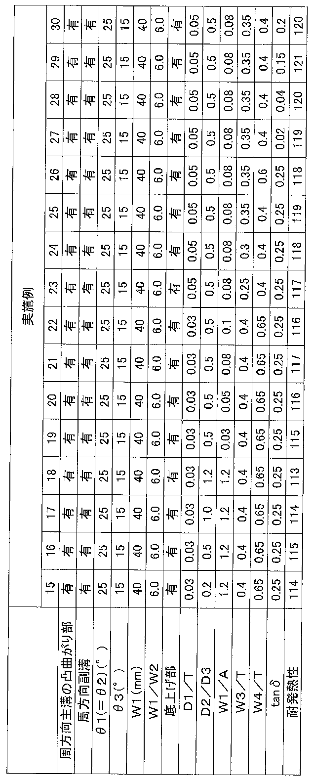
比較例2および実施例1~4の比較により、センターラグ溝のタイヤ周方向に対する傾斜角が55~75°の範囲で、より耐発熱性能を向上させることができることがわかる。
実施例4、6~9を比較すると、周方向副溝の幅W1が7mm以上60mm以下の範囲において、さらに耐発熱性能を向上させることができることがわかる。また、周方向副溝の幅W1とセンターラグ溝の幅W2との比W1/W2が1.0以上8.5以下の範囲において、さらに耐発熱性能を向上させることができることがわかる。
実施例7、10を比較すると、底上げ部を設けることで、より一層耐発熱性能を向上させることができることがわかる。さらに、実施例10~14を比較すると、底上げ部の最も浅い部分の深さD1とトレッド幅Tとの比D1/Tが0.02~0.05の範囲で、さらに耐発熱性能を高めることができることが分かる。
実施例12、15~18を比較すると、周方向副溝の最大溝深さD2とセンターラグ溝の最大溝深さD3との比D2/D3が0.2~1.0の範囲で、さらに耐発熱性能を高めることができることが分かる。
実施例16、19~22を比較すると、周方向副溝の幅W1と周方向主溝11A、11Bの振れ幅Aとの比W1/Aが0.05~1.0の範囲で、耐発熱性能を高めることができることがわかる。
実施例21、23~26を比較すると、一方の周方向主溝11Aの凸曲がり部11bと他方の周方向主溝11Bの凸曲がり部11bとのタイヤ幅方向の間隔W3とトレッド幅Tとの比W3/Tが0.30≦W3/Tであり、かつ、一方の周方向主溝11Aの凸曲がり部11aと他方の周方向主溝11Bの凸曲がり部11aとのタイヤ幅方向の間隔W4とトレッド幅Tとの比W4/TがW4/T≦0.60である範囲で、耐発熱性能を高めることができることがわかる。
実施例25、27~30を比較すると、トレッド部2のタイヤ径方向最外部のゴムの60℃における貯蔵弾性率に対する損失弾性率の比率(tanδ)が0.04以上0.2以下の範囲で、さらに耐発熱性能を高めることができることがわかる。
以上より、本実施形態の効果は明らかである。
2 トレッド部
3 サイドウォール部
4 ビード部
5 ビードコア
6 カーカス層
7 第1の交錯ベルト
8 第2の交錯ベルト
9 第3の交錯ベルト
10 周方向副溝
11A、11B 周方向主溝
11a、11b 凸曲がり部
11c 底上げ部
12A、12B ショルダーラグ溝
14 センターラグ溝
14a 第1の交差部(第1の溝曲がり部)
14b 第2の交差部(第2の溝曲がり部)
14c 第1の端
14d 第2の端
14e 第1の直線
14f 第2の直線
14g 第3の直線
17A、17B 両端閉塞溝
E1、E2 トレッド端
Claims (16)
- トレッドパターンが設けられたトレッド部を有する空気入りタイヤであって、
前記トレッドパターンは、
タイヤ周方向に間隔をあけて複数設けられ、タイヤ赤道線を横切るようにタイヤ赤道線を基準としたタイヤ幅方向の第1の側の半トレッド領域に第1の端を有し、タイヤ幅方向の前記第1の側の反対側である第2の側の半トレッド領域に第2の端を有するセンターラグ溝と、
タイヤ周方向において、複数の前記センターラグ溝のタイヤ周方向の各間隔に設けられるラグ溝であって、前記半トレッド領域のそれぞれにおいて、タイヤ幅方向外側に延びて、タイヤ幅方向外側の端がタイヤ幅方向の両側にある接地端に開口し、前記ラグ溝が有するタイヤ幅方向内側の端のタイヤ幅方向の位置が、前記第1の端又は前記第2の端のタイヤ幅方向の位置に比べてタイヤ幅方向外側にあるショルダーラグ溝と、
前記半トレッド領域のそれぞれにおいて、前記第1の端又は第2の端と、前記ショルダーラグ溝のタイヤ幅方向の内側の端を交互に接続してタイヤ周上全周にわたって波形状に形成され、前記ショルダーラグ溝より溝幅が狭い一対の周方向主溝と、
前記センターラグ溝と前記一対の周方向主溝によって画されてタイヤ周方向に一列に複数形成されたセンターブロックと、
タイヤ赤道線に沿ってタイヤ周上全周にわたって形成され、前記センターラグ溝と交差する周方向副溝と、
を有し、
前記第1の端と、前記センターラグ溝が前記周方向副溝の第1の側の溝壁と交差する第1の交差部と、を結ぶ直線のタイヤ周方向に対する傾斜角度は55°以上75°以下の範囲であり、
前記第2の端と、前記センターラグ溝が前記周方向副溝の第2の側の溝壁と交差する第2の交差部と、を結ぶ直線のタイヤ周方向に対する傾斜角度は55°以上75°以下の範囲であることを特徴とする重荷重用空気入りタイヤ。 - 前記周方向副溝の溝幅をW1としたとき、W1は7mm以上60mm以下の範囲である、請求項1に記載の重荷重用空気入りタイヤ。
- 前記周方向副溝の溝幅をW1、前記センターラグ溝の溝幅をW2としたとき、W1/W2は1.0以上8.5以下の範囲である、請求項1又は2に記載の重荷重用空気入りタイヤ。
- 前記一対の周方向主溝それぞれにおいて、溝深さが部分的に浅くなった底上げ部を備える、請求項1~3のいずれか一項に記載の重荷重用空気入りタイヤ。
- 前記底上げ部における溝深さをD1、前記トレッド部のタイヤ幅方向のトレッド幅をTとしたとき、D1/T<0.05である、請求項4に記載の重荷重用空気入りタイヤ。
- 前記周方向副溝の最大深さをD2、前記センターラグ溝の最大深さをD3としたとき、0.2≦D2/D3≦1.0である、請求項1~5のいずれか一項に記載の重荷重用空気入りタイヤ。
- 前記周方向主溝の波形状の振れ幅をAとしたとき、前記周方向副溝の溝幅W1に対し、0.05≦W1/A≦1.0である、請求項1~6のいずれか一項に記載の重荷重用空気入りタイヤ。
- 前記空気入りタイヤに規格空気圧(700kPa)で空気を充填し、規格荷重(617.81kN)を載荷したときの前記トレッド部の接地領域に対する溝面積の比率をRとしたとき、R≦0.35である、請求項1~7のいずれか一項に記載の重荷重用空気入りタイヤ。
- 前記センターラグ溝の両端間のタイヤ幅方向の間隔をW3、前記半トレッド領域の一方のショルダーラグ溝のタイヤ幅方向の内側の端と前記半トレッド領域の他方のショルダーラグ溝のタイヤ幅方向の内側の端とのタイヤ幅方向の間隔をW4、前記トレッド部のタイヤ幅方向のトレッド幅をTとしたとき、0.30≦W3/T<W4/T≦0.60である、請求項1~8のいずれか一項に記載の重荷重用空気入りタイヤ。
- 前記トレッド部のタイヤ径方向最外部のゴムは、60℃における貯蔵弾性率に対する損失弾性率の比率(tanδ)が0.04以上0.2以下の範囲である、請求項1~9のいずれか一項に記載の重荷重用空気入りタイヤ。
- 前記周方向主溝に対応して前記センターブロックに角部が形成され、前記角部のなす角は、鈍角である、請求項1~10のいずれか一項に記載の重荷重用空気入りタイヤ。
- 前記周方向主溝の溝幅および前記センターラグ溝の溝幅は7mm以上20mm以下の範囲である、請求項1~11のいずれか一項に記載の重荷重用空気入りタイヤ。
- 前記周方向主溝よりも接地端側の領域には、前記周方向主溝および前記ショルダーラグ溝から離間する位置に両端を有し、タイヤ幅方向に延在する両端閉塞溝を有する、請求項1~12のいずれか一項に記載の重荷重用空気入りタイヤ。
- 建設用車両または産業用車両に装着される、請求項1~13のいずれか1項に記載の重荷重用空気入りタイヤ。
- 前記センターラグ溝は、
前記第1の側においてタイヤ周方向の第3の側に突出するように屈曲又は湾曲する第1の溝曲がり部と、
前記第2の側においてタイヤ周方向の前記第3の側の反対側である第4の側に突出するように屈曲又は湾曲する第2の溝曲がり部とを有し、
前記センターラグ溝の溝幅方向の中心位置に関し、前記第1の端と前記第1の溝曲がり部がタイヤ周方向の前記第3の側に突出する突出端とを結ぶ第1直線のタイヤ幅方向に対する傾斜角度、および、前記第2の端と前記第2の溝曲がり部がタイヤ周方向の前記第4の側に突出する突出端とを結ぶ第2直線のタイヤ幅方向に対する傾斜角度は、前記センターラグ溝の前記第1の端と前記第2の端を結ぶ第3直線のタイヤ幅方向に対する傾斜角度よりも大きい、請求項1~14のいずれか一項に記載の重荷重用空気入りタイヤ。 - 前記センターラグ溝は、
前記第1の側においてタイヤ周方向の第3の側に突出するように屈曲又は湾曲する第1の溝曲がり部と、
前記第2の側においてタイヤ周方向の前記第3の側の反対側である第4の側に突出するように屈曲又は湾曲する第2の溝曲がり部とを有し、
前記第1の溝曲がり部は前記第1の交差部に設けられ、
前記第2の溝曲がり部は前記第2の交差部に設けられる、請求項1~14のいずれか一項に記載の重荷重用空気入りタイヤ。
Priority Applications (5)
| Application Number | Priority Date | Filing Date | Title |
|---|---|---|---|
| CN201580038835.9A CN106536227B (zh) | 2014-07-23 | 2015-07-23 | 充气轮胎 |
| JP2015536689A JP6229725B2 (ja) | 2014-07-23 | 2015-07-23 | 重荷重用空気入りタイヤ |
| AU2015293163A AU2015293163B2 (en) | 2014-07-23 | 2015-07-23 | Heavy duty pneumatic tire |
| US15/328,440 US9987885B2 (en) | 2014-07-23 | 2015-07-23 | Heavy duty pneumatic tire |
| RU2017105483A RU2633457C1 (ru) | 2014-07-23 | 2015-07-23 | Пневматическая шина |
Applications Claiming Priority (4)
| Application Number | Priority Date | Filing Date | Title |
|---|---|---|---|
| JP2014-149824 | 2014-07-23 | ||
| JP2014149824 | 2014-07-23 | ||
| JPPCT/JP2015/063719 | 2015-05-13 | ||
| PCT/JP2015/063719 WO2016013276A1 (ja) | 2014-07-23 | 2015-05-13 | 重荷重用空気入りタイヤ |
Publications (1)
| Publication Number | Publication Date |
|---|---|
| WO2016013603A1 true WO2016013603A1 (ja) | 2016-01-28 |
Family
ID=55163127
Family Applications (1)
| Application Number | Title | Priority Date | Filing Date |
|---|---|---|---|
| PCT/JP2015/070933 Ceased WO2016013603A1 (ja) | 2014-07-23 | 2015-07-23 | 空気入りタイヤ |
Country Status (6)
| Country | Link |
|---|---|
| US (1) | US9987885B2 (ja) |
| JP (1) | JP6229725B2 (ja) |
| CN (1) | CN106536227B (ja) |
| AU (1) | AU2015293163B2 (ja) |
| RU (1) | RU2633457C1 (ja) |
| WO (1) | WO2016013603A1 (ja) |
Cited By (2)
| Publication number | Priority date | Publication date | Assignee | Title |
|---|---|---|---|---|
| JP2017214029A (ja) * | 2016-06-02 | 2017-12-07 | 住友ゴム工業株式会社 | ラグ付きタイヤ |
| JP2021094958A (ja) * | 2019-12-16 | 2021-06-24 | 住友ゴム工業株式会社 | タイヤ |
Families Citing this family (4)
| Publication number | Priority date | Publication date | Assignee | Title |
|---|---|---|---|---|
| CN107053960B (zh) * | 2017-03-28 | 2019-02-19 | 正新橡胶(中国)有限公司 | 一种轮胎 |
| JP7144308B2 (ja) * | 2018-12-19 | 2022-09-29 | 株式会社ブリヂストン | 加硫成形用金型 |
| CN111137073B (zh) * | 2020-01-17 | 2024-09-06 | 正新橡胶(中国)有限公司 | 一种重载荷轮胎 |
| USD1118472S1 (en) | 2024-10-09 | 2026-03-17 | Mark Thornburg | Tire |
Citations (7)
| Publication number | Priority date | Publication date | Assignee | Title |
|---|---|---|---|---|
| JP2004098914A (ja) * | 2002-09-11 | 2004-04-02 | Bridgestone Corp | 重荷重用タイヤ |
| JP2004224131A (ja) * | 2003-01-21 | 2004-08-12 | Sumitomo Rubber Ind Ltd | 重荷重用ラジアルタイヤ |
| WO2006001202A1 (ja) * | 2004-06-23 | 2006-01-05 | Bridgestone Corporation | 空気入りタイヤ |
| JP2006151083A (ja) * | 2004-11-26 | 2006-06-15 | Bridgestone Corp | 重荷重車両用タイヤ |
| JP2007191093A (ja) * | 2006-01-20 | 2007-08-02 | Bridgestone Corp | 建設車両用タイヤ |
| JP2008279976A (ja) * | 2007-05-14 | 2008-11-20 | Bridgestone Corp | 建設車両用重荷重空気入りラジアルタイヤ |
| JP2010125999A (ja) * | 2008-11-27 | 2010-06-10 | Bridgestone Corp | タイヤ |
Family Cites Families (9)
| Publication number | Priority date | Publication date | Assignee | Title |
|---|---|---|---|---|
| JP3569056B2 (ja) | 1995-11-15 | 2004-09-22 | 株式会社ブリヂストン | 空気入りタイヤ |
| JP3076553B2 (ja) * | 1998-12-21 | 2000-08-14 | 住友ゴム工業株式会社 | 重荷重用タイヤ |
| EP1914092B1 (en) * | 2005-08-08 | 2010-12-01 | Bridgestone Corporation | Tire for construction vehicle |
| JP2010095092A (ja) * | 2008-10-15 | 2010-04-30 | Bridgestone Corp | タイヤ |
| FR2978377B1 (fr) * | 2011-07-28 | 2014-12-26 | Michelin Soc Tech | Sculpture pour pneus de vehicule de genie civil |
| JP6164209B2 (ja) * | 2012-03-23 | 2017-07-19 | 横浜ゴム株式会社 | 空気入りタイヤ |
| JP5399528B2 (ja) * | 2012-04-11 | 2014-01-29 | 東洋ゴム工業株式会社 | 一組の空気入りタイヤ、及び空気入りタイヤの装着構造 |
| JP5667614B2 (ja) * | 2012-10-02 | 2015-02-12 | 住友ゴム工業株式会社 | 空気入りタイヤ |
| JP6243233B2 (ja) * | 2014-01-17 | 2017-12-06 | 株式会社ブリヂストン | タイヤ |
-
2015
- 2015-07-23 RU RU2017105483A patent/RU2633457C1/ru active
- 2015-07-23 CN CN201580038835.9A patent/CN106536227B/zh not_active Expired - Fee Related
- 2015-07-23 AU AU2015293163A patent/AU2015293163B2/en not_active Ceased
- 2015-07-23 US US15/328,440 patent/US9987885B2/en active Active
- 2015-07-23 JP JP2015536689A patent/JP6229725B2/ja active Active
- 2015-07-23 WO PCT/JP2015/070933 patent/WO2016013603A1/ja not_active Ceased
Patent Citations (7)
| Publication number | Priority date | Publication date | Assignee | Title |
|---|---|---|---|---|
| JP2004098914A (ja) * | 2002-09-11 | 2004-04-02 | Bridgestone Corp | 重荷重用タイヤ |
| JP2004224131A (ja) * | 2003-01-21 | 2004-08-12 | Sumitomo Rubber Ind Ltd | 重荷重用ラジアルタイヤ |
| WO2006001202A1 (ja) * | 2004-06-23 | 2006-01-05 | Bridgestone Corporation | 空気入りタイヤ |
| JP2006151083A (ja) * | 2004-11-26 | 2006-06-15 | Bridgestone Corp | 重荷重車両用タイヤ |
| JP2007191093A (ja) * | 2006-01-20 | 2007-08-02 | Bridgestone Corp | 建設車両用タイヤ |
| JP2008279976A (ja) * | 2007-05-14 | 2008-11-20 | Bridgestone Corp | 建設車両用重荷重空気入りラジアルタイヤ |
| JP2010125999A (ja) * | 2008-11-27 | 2010-06-10 | Bridgestone Corp | タイヤ |
Cited By (3)
| Publication number | Priority date | Publication date | Assignee | Title |
|---|---|---|---|---|
| JP2017214029A (ja) * | 2016-06-02 | 2017-12-07 | 住友ゴム工業株式会社 | ラグ付きタイヤ |
| JP2021094958A (ja) * | 2019-12-16 | 2021-06-24 | 住友ゴム工業株式会社 | タイヤ |
| JP7516753B2 (ja) | 2019-12-16 | 2024-07-17 | 住友ゴム工業株式会社 | タイヤ |
Also Published As
| Publication number | Publication date |
|---|---|
| JPWO2016013603A1 (ja) | 2017-04-27 |
| CN106536227A (zh) | 2017-03-22 |
| RU2633457C1 (ru) | 2017-10-12 |
| AU2015293163A9 (en) | 2017-03-23 |
| AU2015293163A1 (en) | 2017-03-02 |
| AU2015293163B2 (en) | 2017-08-03 |
| US20170217255A1 (en) | 2017-08-03 |
| CN106536227B (zh) | 2018-03-02 |
| US9987885B2 (en) | 2018-06-05 |
| JP6229725B2 (ja) | 2017-11-15 |
Similar Documents
| Publication | Publication Date | Title |
|---|---|---|
| JP6229727B2 (ja) | 重荷重用空気入りタイヤ | |
| JP6229725B2 (ja) | 重荷重用空気入りタイヤ | |
| JP6229735B2 (ja) | 重荷重用空気入りタイヤ | |
| WO2016013604A1 (ja) | 重荷重用空気入りタイヤ | |
| JP6229722B2 (ja) | 重荷重用空気入りタイヤ | |
| JP6432518B2 (ja) | 空気入りタイヤ | |
| JP6229734B2 (ja) | 空気入りタイヤ | |
| JP6237970B1 (ja) | 重荷重用空気入りタイヤ | |
| JP6229723B2 (ja) | 重荷重用空気入りタイヤ | |
| JP6229724B2 (ja) | 重荷重用空気入りタイヤ | |
| JP5910795B1 (ja) | 重荷重用空気入りタイヤ |
Legal Events
| Date | Code | Title | Description |
|---|---|---|---|
| ENP | Entry into the national phase |
Ref document number: 2015536689 Country of ref document: JP Kind code of ref document: A |
|
| 121 | Ep: the epo has been informed by wipo that ep was designated in this application |
Ref document number: 15824345 Country of ref document: EP Kind code of ref document: A1 |
|
| NENP | Non-entry into the national phase |
Ref country code: DE |
|
| WWE | Wipo information: entry into national phase |
Ref document number: 15328440 Country of ref document: US |
|
| ENP | Entry into the national phase |
Ref document number: 2017105483 Country of ref document: RU Kind code of ref document: A |
|
| ENP | Entry into the national phase |
Ref document number: 2015293163 Country of ref document: AU Date of ref document: 20150723 Kind code of ref document: A |
|
| 122 | Ep: pct application non-entry in european phase |
Ref document number: 15824345 Country of ref document: EP Kind code of ref document: A1 |