WO2016013477A1 - 発電機 - Google Patents
発電機 Download PDFInfo
- Publication number
- WO2016013477A1 WO2016013477A1 PCT/JP2015/070375 JP2015070375W WO2016013477A1 WO 2016013477 A1 WO2016013477 A1 WO 2016013477A1 JP 2015070375 W JP2015070375 W JP 2015070375W WO 2016013477 A1 WO2016013477 A1 WO 2016013477A1
- Authority
- WO
- WIPO (PCT)
- Prior art keywords
- generator
- core
- winding
- initial excitation
- field
- Prior art date
Links
Images


Classifications
-
- H—ELECTRICITY
- H02—GENERATION; CONVERSION OR DISTRIBUTION OF ELECTRIC POWER
- H02K—DYNAMO-ELECTRIC MACHINES
- H02K11/00—Structural association of dynamo-electric machines with electric components or with devices for shielding, monitoring or protection
- H02K11/04—Structural association of dynamo-electric machines with electric components or with devices for shielding, monitoring or protection for rectification
- H02K11/049—Rectifiers associated with stationary parts, e.g. stator cores
- H02K11/05—Rectifiers associated with casings, enclosures or brackets
-
- F—MECHANICAL ENGINEERING; LIGHTING; HEATING; WEAPONS; BLASTING
- F03—MACHINES OR ENGINES FOR LIQUIDS; WIND, SPRING, OR WEIGHT MOTORS; PRODUCING MECHANICAL POWER OR A REACTIVE PROPULSIVE THRUST, NOT OTHERWISE PROVIDED FOR
- F03D—WIND MOTORS
- F03D9/00—Adaptations of wind motors for special use; Combinations of wind motors with apparatus driven thereby; Wind motors specially adapted for installation in particular locations
- F03D9/20—Wind motors characterised by the driven apparatus
- F03D9/25—Wind motors characterised by the driven apparatus the apparatus being an electrical generator
-
- H—ELECTRICITY
- H02—GENERATION; CONVERSION OR DISTRIBUTION OF ELECTRIC POWER
- H02K—DYNAMO-ELECTRIC MACHINES
- H02K1/00—Details of the magnetic circuit
- H02K1/06—Details of the magnetic circuit characterised by the shape, form or construction
- H02K1/12—Stationary parts of the magnetic circuit
-
- H—ELECTRICITY
- H02—GENERATION; CONVERSION OR DISTRIBUTION OF ELECTRIC POWER
- H02K—DYNAMO-ELECTRIC MACHINES
- H02K1/00—Details of the magnetic circuit
- H02K1/06—Details of the magnetic circuit characterised by the shape, form or construction
- H02K1/22—Rotating parts of the magnetic circuit
-
- H—ELECTRICITY
- H02—GENERATION; CONVERSION OR DISTRIBUTION OF ELECTRIC POWER
- H02K—DYNAMO-ELECTRIC MACHINES
- H02K11/00—Structural association of dynamo-electric machines with electric components or with devices for shielding, monitoring or protection
- H02K11/0094—Structural association with other electrical or electronic devices
-
- H—ELECTRICITY
- H02—GENERATION; CONVERSION OR DISTRIBUTION OF ELECTRIC POWER
- H02K—DYNAMO-ELECTRIC MACHINES
- H02K7/00—Arrangements for handling mechanical energy structurally associated with dynamo-electric machines, e.g. structural association with mechanical driving motors or auxiliary dynamo-electric machines
- H02K7/18—Structural association of electric generators with mechanical driving motors, e.g. with turbines
- H02K7/1807—Rotary generators
- H02K7/1823—Rotary generators structurally associated with turbines or similar engines
- H02K7/183—Rotary generators structurally associated with turbines or similar engines wherein the turbine is a wind turbine
-
- H—ELECTRICITY
- H02—GENERATION; CONVERSION OR DISTRIBUTION OF ELECTRIC POWER
- H02M—APPARATUS FOR CONVERSION BETWEEN AC AND AC, BETWEEN AC AND DC, OR BETWEEN DC AND DC, AND FOR USE WITH MAINS OR SIMILAR POWER SUPPLY SYSTEMS; CONVERSION OF DC OR AC INPUT POWER INTO SURGE OUTPUT POWER; CONTROL OR REGULATION THEREOF
- H02M7/00—Conversion of ac power input into dc power output; Conversion of dc power input into ac power output
-
- H—ELECTRICITY
- H02—GENERATION; CONVERSION OR DISTRIBUTION OF ELECTRIC POWER
- H02P—CONTROL OR REGULATION OF ELECTRIC MOTORS, ELECTRIC GENERATORS OR DYNAMO-ELECTRIC CONVERTERS; CONTROLLING TRANSFORMERS, REACTORS OR CHOKE COILS
- H02P9/00—Arrangements for controlling electric generators for the purpose of obtaining a desired output
- H02P9/08—Control of generator circuit during starting or stopping of driving means, e.g. for initiating excitation
-
- Y—GENERAL TAGGING OF NEW TECHNOLOGICAL DEVELOPMENTS; GENERAL TAGGING OF CROSS-SECTIONAL TECHNOLOGIES SPANNING OVER SEVERAL SECTIONS OF THE IPC; TECHNICAL SUBJECTS COVERED BY FORMER USPC CROSS-REFERENCE ART COLLECTIONS [XRACs] AND DIGESTS
- Y02—TECHNOLOGIES OR APPLICATIONS FOR MITIGATION OR ADAPTATION AGAINST CLIMATE CHANGE
- Y02E—REDUCTION OF GREENHOUSE GAS [GHG] EMISSIONS, RELATED TO ENERGY GENERATION, TRANSMISSION OR DISTRIBUTION
- Y02E10/00—Energy generation through renewable energy sources
- Y02E10/70—Wind energy
- Y02E10/72—Wind turbines with rotation axis in wind direction
Definitions
- the present invention relates to a permanent magnet-less generator used as, for example, a small wind generator or a generator using running water.
- Induction generators do not require excitation in the rotor windings, but are not suitable for small generators because they must be linked to the system and rotated at a high rotational speed. Therefore, a synchronous generator is often used in a small wind power generator or the like.
- a normal synchronous generator uses a permanent magnet for generating a field, the rare metal that is a component of the permanent magnet is expensive and the entire generator is expensive.
- cogging is generated at the time of starting, and the starting torque is increased by the cogging torque.
- Patent Document 1 A self-excited synchronous generator that solves these problems and does not require external magnets and external power supply has been proposed (Patent Document 1).
- This generator uses the residual magnetism of the iron core to increase the current that flows in the field winding by self-excitation, so that the magnetic flux required for power generation can be supplied with an expensive permanent magnet or an external power source for excitation. Produced without need.
- the self-excited generator of Patent Document 1 has excellent advantages as described above. However, if the generator is stopped or the generator is disassembled, the residual magnetism of the generator core becomes weak. If the residual magnetism of the generator core is weak, the magnetic force necessary for the initial excitation is insufficient, and it is necessary that the power generation is not started or the rotational speed at which the power generation is started is somewhat high. Therefore, in a power generation method that requires a period of stoppage or generation at low speed, such as wind power generation or power generation using running water, the self-excited generator has insufficient reliability of power generation start. Become.
- Patent Document 2 can also ensure the start of power generation when resuming rotation after stopping rotation, but the reluctance generator has little practical experience, and there is an unclear concern in practical use.
- An object of the present invention is that permanent magnets that generate magnetic flux to obtain normal generated power and power supply for external excitation from the outside are unnecessary, and power generation can be reliably started by restarting rotation even after rotation is stopped. Is to provide a generator.
- the generator of the present invention includes an output iron core around which an output winding is wound, and a field iron core around which a main field winding and a subfield winding are wound, and any of the output iron core and the field iron core is provided.
- One of them is a stator, the other is a rotor, a first rectifier element is connected to the main field winding, a second rectifier element is connected to the subfield winding, and relative rotation between the stator and the rotor
- Initial excitation means for applying a magnetic force to one or both of the output core and the field core is provided to the extent necessary for the initial excitation of power generation.
- magnetizing means for magnetizing one or both of the output core and the field core.
- magnetization refers to magnetization so that residual magnetism is generated after the completion of the magnetization process.
- the magnetizing means is capable of being magnetized to such an extent that it can generate the magnetic force necessary for the initial excitation of power generation, and is significantly smaller than an external power source in a separately excited generator. It's fine.
- the magnetizing means may be configured to pass a magnetizing current through any of the output winding, the main field winding, and the sub-field winding. By energizing the winding with a current larger than a certain level, the iron core can be magnetized. If the magnetizing means is configured to pass a magnetizing current through the winding, the magnetizing means can be configured simply.
- the magnetizing current may be a direct current or a pulsed current. If it is a direct current, the magnetizing means can be configured more simply. When the current is pulsed, it is possible to easily apply a current as strong as necessary for magnetization or to adjust the magnitude of the magnetizing current.
- Magnetizing means configured to energize the winding with a magnetizing current includes a magnetizing power source comprising a secondary battery or a capacitor, the output winding energizing the magnetizing current, and the magnetizing power source. Or a switching element interposed between the main field winding and the sub field winding and the magnetizing power source. With this configuration, the magnetizing means can be a simple configuration.
- the initial excitation means may be an initial excitation magnet comprising a permanent magnet that is provided in the field iron core and generates a magnetic force necessary for initial excitation of power generation. If the initial excitation means is an initial excitation magnet made of a permanent magnet, a circuit such as a magnetization means is unnecessary, and the circuit configuration is simplified. An initial exciting magnet made of a permanent magnet is provided. However, in a self-excited generator, the magnetic flux increases as it rotates as described above. Since the initial excitation magnet is a permanent magnet that generates a magnetic force necessary for such initial excitation, it is a magnet that generates a very weak magnetic force compared to a permanent magnet for obtaining a normal, that is, always generated power. That's it.
- the initial excitation magnet may be embedded in a surface of the magnetic pole of the field core facing the output iron core, or may be embedded between adjacent magnetic pole portions in the field iron core.
- the direction of the magnetic flux generated by the initial excitation magnet is preferably the same as the direction of the magnetic flux generated by the excitation current flowing in the main field winding. . By aligning the direction of the magnetic flux in this way, the magnetic force generated by the initial excitation magnet is effectively used for the initial excitation at the time of starting rotation.
- the generator may be configured as a wind power generator in which the rotor is rotationally driven by a windmill.
- the rotor is rotationally driven by a windmill.
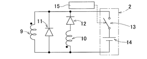
- FIG. 1 is an explanatory diagram combining a broken front view of a generator main body 1 of a generator G according to the present embodiment and an electric circuit diagram of a magnetizing means 2 and an external load 3.
- FIG. 2 is a schematic diagram in which the generator main body 1 of FIG. This embodiment is an example in which the initial exciting means is the magnetizing means 2.
- the generator G includes a generator body 1 including an annular stator 4 and a rotor 5 that is installed inside the stator 4 so as to be rotatable around the center of the stator 4.
- the stator 4 includes an output iron core 6 and an output winding 7.
- This embodiment is an example applied to a two-pole generator, and the output iron core 6 is formed with tooth-shaped magnetic pole portions 6b protruding inward at two locations in the circumferential direction of an annular yoke portion 6a.
- the output winding 7 is wound around each magnetic pole portion 6b. As shown in FIG.
- the output windings 7 of the magnetic pole portions 6 b are connected in series so that different magnetic poles appear on the magnetic pole surfaces facing the inner diameter side of the adjacent magnetic pole portions 6 b of the output iron core 6. Both ends of the output winding 7 become terminals 7a and 7b, and an external load 3 is connected to these terminals 7a and 7b as shown in FIG.
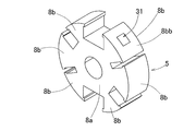
- the rotor 5 includes a field iron core 8, a main field winding 9 and a sub-field winding 10 wound around the field iron core 8.
- the field iron core 8 is provided with a plurality of tooth-shaped magnetic pole portions 8b protruding in the circumferential direction on the outer periphery of an iron core body 8a having a center hole.
- Three magnetic pole portions 8 b are provided for each magnetic pole portion 6 b of the output iron core 6.
- the main field winding 9 is wound over two adjacent magnetic pole portions 8b and 8b.
- the main field windings 9 wound around the two magnetic pole portions 8b and 8b are connected in series so that different magnetic poles appear on the magnetic pole surfaces of the adjacent magnetic pole sets in pairs. ing.
- the sub-field winding 10 is shifted in phase by the amount of the main field winding 9 and one magnetic pole portion 8b, and is spread over two adjacent magnetic pole portions 8b and 8b in the same manner as the main field winding 9. It is rolled up.
- the sub-field windings 10 wound over the two magnetic pole portions 8b and 8b are connected in series so that different magnetic poles appear on the magnetic pole surfaces of the adjacent magnetic pole pairs in a pair. ing.
- terminals 9a and 9b are formed at both ends of the series connection body of the main field winding 9
- terminals 10a and 10b are formed at both ends of the series connection body of the sub-field winding 10. Is formed.
- the first rectifying element 11 is connected in parallel to the main field winding 9, and a current in a direction that allows the first rectifying element 11 to flow flows through the main field winding 9.
- the subfield winding 10 is connected in series with the main field winding 9, and the second rectifying element 12 is connected in series with the subfield winding 10, and the subfield winding 10 has a main field winding. Only current in the same direction as line 9 flows.
- the arrows in the figure indicate the direction of current flow.
- This generator G is a self-excited generator having such a subfield winding 10 and is provided with a magnetizing means 2 serving as an initial excitation means, as shown in FIG.
- a magnetizing power source 14 is connected to the output winding 7 in parallel with the external load 3 via a switching element 13.
- the magnetizing means 2 is configured by the magnetizing power source 14 and the switching element 13.
- the magnetizing power source 14 is a storage means such as a secondary battery or a capacitor. When the external load 3 is a secondary battery, it may be used as a magnetizing power source.
- a current of a predetermined magnitude may be passed for a very short time.
- the degree of magnetization may be such that residual magnetism necessary for initial excitation for the start of power generation is obtained, and is determined by the voltage and the magnitude of current due to the on-time of the switching element 13.
- the opening / closing operation of the switching element 13 is performed by the opening / closing control means 15.
- the opening / closing control means 15 monitors the detection signal of the rotation detecting means 16 that detects the rotation of the rotor 5, and when it is detected that the rotor 5 has started rotating from a stationary state, the switching element 13 is magnetized. Turn it on only for the required setting time.
- the opening / closing control means 15 turns on the switching element 13 only when the rotation starts after the rotor 5 stops for a set time or longer.
- the switching element 13 may be controlled to be turned on according to the set conditions.
- the magnetizing power source 14 is connected to the output winding 7. However, as shown in FIG. 4, the main field winding 9 and the subfield winding 10 are magnetized via the switching element 13.
- a power source 14 may be connected. Also in this example, the magnetizing power source 14 is a secondary battery or a capacitor. In order to magnetize, a current of a predetermined magnitude may be passed for a very short time.
- the switching element 13 is controlled to be opened and closed by the opening / closing control means 15 as in the embodiment of FIG.
- the operation of the first embodiment will be described.
- the operation when the rotor 5 is rotating and generating power will be described.
- a current in a direction that allows the first rectifying element 11 to flow through the main field winding 9. Flows. Therefore, a magnetic flux having a direction determined by a current that can be passed through the main field winding 9 is generated.
- due to electromagnetic induction a current flows in a direction that prevents a decrease in magnetic flux in the same direction as a magnetic flux generated by the current, but a current does not flow in a direction that prevents an increase in magnetic flux. Therefore, the decrease of the magnetic flux is prevented, but the increase of the magnetic flux is not prevented.
- a second rectifying element 12 is connected in series to the subfield winding 10, and only a current in the same direction as the main field winding 9 flows.
- the current flows through the main field winding 9 due to the residual magnetism of the output core 6 or the field core 8. With this current, the magnetic flux generated by the main field winding 9 changes the magnetic flux linked to the sub field winding 10, and a voltage is generated in the sub field winding 10. With this voltage, the sub-field winding 10 supplies a current through the main field winding 9 and increases the current flowing through the main field winding 9. When no current is supplied to the subfield winding 10 without inducing voltage, a return current flows through the commutator 11 in the main field winding 9 to maintain the magnetic flux of the main field winding 9.
- the magnetic flux linked to the subfield winding 10 is also increased, and a larger current is supplied to the main field winding 9. 9 is supplied. In this manner, the current in the main field winding 9 gradually increases, and a field magnetic flux necessary for power generation is created. Due to the relative motion of the output iron core 6 and the field iron core 8, the flux linkage of the output winding 7 changes to generate a voltage.
- the switching element 13 of the magnetizing means 2 is turned on to pass a magnetizing current from the magnetizing power source 14 to the output winding 7, and the output iron core 6. Magnetize. Since the magnetic flux gradually increases as the rotation continues as described above, the degree of magnetization may be such that the residual magnetism necessary for the initial excitation for the start of power generation is obtained. For this reason, in order to magnetize, a current of a predetermined magnitude may be passed for a very short time. By this magnetization, even after the rotor 5 is stopped for a long time, power generation is reliably started by resuming the rotation.
- the switching element 13 of the magnetizing means 2 is turned on and a magnetizing current is supplied from the magnetizing power supply 14 to the main field winding 9.
- the field iron core 8 is magnetized. Even when the field core 8 is magnetized in this way, power generation is started even after the rotor 5 has been stopped for a long time.
- the generator G configured as shown in FIG. 4, the following advantages are obtained. Since it is a self-excited type that performs excitation using the sub-field winding 10, power generation can be performed without the need for a permanent magnet or an external power source that supplies power for external excitation from the outside. Since no permanent magnet is used, no cogging torque is generated and the rotor 5 can be rotated with a small torque. Although it is self-excited, the magnetizing means 2 for magnetizing one of the iron cores of the generator G is provided to such an extent that a magnetic force required for initial excitation of power generation can be generated. Even after maintenance and at low speed, power generation can be started reliably. Although the magnetizing means 2 is necessary, the magnetizing means 2 is sufficient if it can be magnetized to such an extent that it can generate a magnetic force necessary for initial excitation of power generation. Compared to an external power source in, it can be much smaller.
- FIGS. 5 and 6 show still another embodiment of the present invention.
- This embodiment is an example in which, in the first embodiment shown in FIGS. 1 to 3, an initial exciting magnet 31 is provided instead of the magnetizing means 2 for the initial exciting means.
- the initial excitation magnet 31 is embedded in the field core 8 as shown in FIG.
- the initial excitation magnet 31 is a permanent magnet that generates a magnetic force necessary for initial excitation of power generation, and a magnet that is as small as possible is used in a range that allows for a margin so that the magnetic force necessary for initial excitation can be reliably generated.
- a ferrite magnet that is less expensive than a rare earth magnet can be used.
- the initial excitation magnet 31 has a direction in which the direction of the generated magnetic flux is the same as the direction of the magnetic flux generated by the excitation current flowing in the main field winding 9.
- the number of the initial excitation magnets 31 is the same as the number of the magnetic pole portions 6b of the output iron core 6, and is two, but may be one.
- the magnetic pole part 6b of the output iron core 6 is 4 poles, 8 poles, or 16 poles, the number may be two or the number according to the number of magnetic poles.
- the initial excitation magnet 31 is provided over the entire axial thickness of the magnetic pole portion 8b from which the field core 8 protrudes, as in the example of FIG.
- the initial excitation magnet 31 is divided into two divided magnetic pole portions 8ba and 8ba arranged in the circumferential direction of the magnetic pole portion 8b of the field iron core 8, and interposed between the two divided magnetic pole portions 8ba and 8ba. ing.
- the initial excitation magnet 31 may be embedded in a surface 8 bb of the magnetic pole portion 8 b of the field core 8 that faces the output core 6.
- the initial excitation magnet 31 is embedded in the center of the facing surface 8bb of the magnetic pole portion 8b.
- the operation of the generator G according to this embodiment will be described. Since the operation of the generator G during continuous rotation is the same as that in the first embodiment, description thereof is omitted.
- power is generated while the rotor 5 is rotating. However, if the rotor 5 is stopped for a long time, both the output iron core 6 and the field iron core 8 There is no residual magnetism, or the residual magnetism is insufficient and power generation cannot be started. Therefore, in this embodiment, the initial excitation magnet 31 is provided, and the power generation is reliably started by resuming the rotation even after the rotor 5 is stopped for a long time by the magnetic flux generated by the initial excitation magnet 31. .
- the generator G having this configuration provides the following advantages. Since it is a self-excited type that performs excitation using the sub-field winding 10, power generation can be performed without the need for a permanent magnet for power generation or an external power source that supplies power for external excitation from the outside. Since no permanent magnet for power generation is used, no cogging torque is generated and the rotor 5 can be rotated with a small torque. Although self-excited, the initial excitation magnet 31 is provided in the field core 8 so that power generation can be reliably started even after rotation is stopped, after disassembly and maintenance, or at low speed. Can do.
- the initial excitation magnet 31 is provided, in the self-excited generator, the magnetic flux increases as it rotates as described above. Therefore, the magnetic force required for the initial excitation is very small. Since the magnet 31 for initial excitation is a permanent magnet that generates a magnetic force necessary for such a small initial excitation, it may be a magnet that generates a very weak magnetic force as compared with a permanent magnet that obtains normal generated power. Therefore, an expensive rare metal is unnecessary, an inexpensive material such as a ferrite magnet is sufficient, a small magnet is sufficient, and the cogging torque is not a problem in practical use. Moreover, unlike a reluctance generator, since it is an improvement of a self-excited generator, it is easy to put it into practical use.
- stator 4 side is the output iron core 6 and the rotor 5 side is the field iron core 8. Conversely, the stator 4 side is the field iron core 8, and the rotor 5 side is the output iron core 6. Also good.
- a two-pole generator is used, but a multi-pole generator such as a 4-pole, 8-pole, or 16-pole generator may be used.
- the magnetizing means 2 or the initial exciting magnet 31 is provided as the initial exciting means.
- the magnetizing is not performed, but to the extent necessary for the initial excitation of power generation, Means (not shown) for applying a current to any of the windings 7, 8, 9 for a predetermined time at the beginning of rotation so that a magnetic force is generated in one or both of the output core 6 and the field core 8. ) May be provided.
- FIG. 8 shows an example in which the stator 4 side is a field iron core 8 and the rotor 5 side is an output iron core 6 to form a quadrupole generator. Since the principle is the same as that of the first embodiment, the same reference numerals are assigned to the corresponding parts and the description thereof is omitted.
- the initial excitation means is not shown.
- the initial excitation means may be the magnetizing means 2 or the initial excitation magnet 31. When the initial excitation magnet 31 is used, it is provided on the stator 4 side in this embodiment.
- the rotor 5 is attached to a shaft 21 and is rotatably supported by a bearing 23 with respect to the frame 22 together with the shaft 21.
- the stator 4 is fixed to the frame 22.
- the output winding of the rotor 5 is taken out to the fixed side via the slip ring 24 and the brush 25.
- FIG. 10 shows a breakage of the generator G according to the embodiment of FIG. 1 or FIG. 4 or the wind power generator W in which the generator G according to any of the embodiments of FIGS. 5 to 8 is mounted as a generator for wind power generation. It is a side view.
- a nacelle 42 is provided on a support base 41 so as to be horizontally rotatable.
- a main shaft 45 is rotatably supported by a bearing 44.
- a blade (windmill) 46 that is a swirl blade is attached to one end of the main shaft 45 protruding from the casing 43.
- the other end of the main shaft 45 is connected to a speed increaser 47, and an output shaft 48 of the speed increaser 47 is coupled to a rotor shaft of a generator G that is a wind power generator. In this way, the rotor of the generator G is rotationally driven by the blade 46.
- the generator G as a wind power generator, it is possible to start rotation even with a light torque, and to generate power even at a low speed, and in wind power generation using natural forces with large fluctuations. , Can generate electricity efficiently.
- the generator G according to each of the above embodiments can be used for power generation of various energy sources such as power generation using running water and power generation using other natural forces in addition to wind power generation.
- FIGS. 11 to 13 show the results of trial manufacture and magnetic field analysis of the generator configured as shown in FIGS.
- FIG. 11 shows the rising waveform of the coil voltage and the linkage flux by magnetic field analysis. From this figure, it can be seen that the linkage flux of the main coil gradually increases.
- the “main coil” in the figure corresponds to the “main field winding 9” in the embodiment, and the “subcoil” corresponds to the “sub field winding 10” in the embodiment.
- the “rotor coil” corresponds to the “output winding 7”. From FIG. 12 and FIG. 13, the change in the magnetic flux density of each part due to the rotation of the rotor 5 is known.
Abstract
出力巻線(7)が巻かれた出力鉄心(6)と、主界磁巻線(9)および副界磁巻線(10)が巻かれた界磁鉄心(8)とを備え、前記出力鉄心(6)および前記界磁鉄心(8)のいずれか一方がステータ(4)となり、他方がロータ(5)となり、前記主界磁巻線(9)に第1整流素子(11)が接続され、前記副界磁巻線(10)に第2整流素子(12)が接続され、前記ステータ(4)とロータ(5)との相対回転により発電電力を得る自励式の発電機(G)において、発電の初期励磁に必要な程度に、前記出力鉄心(6)および界磁鉄心(8)のいずれか一方または両方に磁力を付与する初期励磁手段(2,31)を設ける。
Description
本出願は、2014年7月24日出願の特願2014-150442,特願2014-150684,および2014年8月11日出願の特願2014-163438の優先権を主張するものであり、その全体を参照により本願の一部をなすものとして引用する。
この発明は、例えば、小型風力発電機や、流水を利用する発電機として用いられる永久磁石レスの発電機に関する。
回転により発電を行う発電機として、誘導発電機や同期発電機がある。誘導発電機はロータの巻線に励磁を必要としないが、系統連係させかつ高い回転速度で回転させる必要があって小型の発電機には適さない。そのため、小型風力発電機等では、同期発電機が用いられることが多い。
しかし、通常の同期発電機は、界磁の生成に永久磁石を用いるため、永久磁石の成分となるレアメタルが高価で発電機全体が高額になる。さらに、同期発電機では、始動時にコギングが発生し、コギングトルクによって始動トルクが大きくなる。このため、小型風力発電機等の僅かな自然力で発電させる発電機には適さない。永久磁石の代わりに電磁石を用いる他励式の同期発電機もあるが、電磁石への外部からの給電の構成が必要で、外部電源により構成が複雑となる。
しかし、通常の同期発電機は、界磁の生成に永久磁石を用いるため、永久磁石の成分となるレアメタルが高価で発電機全体が高額になる。さらに、同期発電機では、始動時にコギングが発生し、コギングトルクによって始動トルクが大きくなる。このため、小型風力発電機等の僅かな自然力で発電させる発電機には適さない。永久磁石の代わりに電磁石を用いる他励式の同期発電機もあるが、電磁石への外部からの給電の構成が必要で、外部電源により構成が複雑となる。
これらの課題を解消し、永久磁石および外部からの給電が不必要な自励式の同期発電機が提案されている(特許文献1)。この発電機は、鉄心の残留磁気を利用して、自己励磁により界磁巻線に流れる電流を増加させて行くことで、発電に必要な磁束を、高価な永久磁石や励磁用の外部電源を必要とせずに作り出している。
この他に、上記課題を解消する発電機として、リラクタンス(磁気抵抗)を利用し、ステータ鉄心に出力巻線および界磁巻線を巻き付け、ロータにはコイルを用いないリラクタンス発電機において、ステータ突極間を磁気的に短絡させるフェライト磁石を設けたものが提案されている(特許文献2)。
特許文献1の自励式の発電機は、上記のように優れた利点があるが、発電を停止したり、発電機を分解したりすると、発電機鉄心の残留磁気が弱くなる。発電機鉄心の残留磁気が弱いと、初期励磁に必要な磁力が不足し、発電を開始しないか、または発電を開始する回転速度がある程度高いことが必要となる。そのため、風力発電や、流水を利用する発電のように、停止する期間が生じたり低速で発電させることが必要な発電方式では、前記自励式の発電機では、発電開始の確実性が不十分となる。
特許文献2の発電機は、回転停止後の回転再開時における発電開始の確実性も得られるが、リラクタンス発電機は実用の実績が少なく、実用化において、今一つ不明な懸念がある。
この発明の目的は、通常の発電電力を得るための磁束をつくる永久磁石、および外部からの他励のための給電が不必要で、かつ回転停止後にも回転の再開により確実に発電を開始できる発電機を提供することである。
この発明の発電機は、出力巻線が巻かれた出力鉄心と、主界磁巻線および副界磁巻線が巻かれた界磁鉄心とを備え、前記出力鉄心および前記界磁鉄心のいずれか一方がステータとなり、他方がロータとなり、前記主界磁巻線に第1整流素子が接続され、前記副界磁巻線に第2整流素子が接続され、前記ステータとロータとの相対回転により発電電力を得る自励式の発電機であって、
発電の初期励磁に必要な程度に、前記出力鉄心および界磁鉄心のいずれか一方または両方に磁力を付与する初期励磁手段が設けられている。
発電の初期励磁に必要な程度に、前記出力鉄心および界磁鉄心のいずれか一方または両方に磁力を付与する初期励磁手段が設けられている。
この構成によると、副界磁巻線を用いて励磁を行う自励式であるため、発電用の永久磁石や、外部からの他励のための給電を行う外部電源を必要とせずに発電が行える。発電用の永久磁石を用いないため、コギングトルクが発生せず、小さなトルクでロータを回転させることができる。自励式であるが、初期励磁手段を設けるため、回転の停止後や分解保守の後であっても、また低速回転であっても、確実に発電を開始することができる。
初期励磁手段は設けるが、自励式の発電機では、回転するに従って磁束が増大するため、初期励磁に必要な磁力は極小さな磁力で済む。このため、初期励磁手段が後述のような着磁手段であれ、また永久磁石であれ、軽微なもので済む。
初期励磁手段は設けるが、自励式の発電機では、回転するに従って磁束が増大するため、初期励磁に必要な磁力は極小さな磁力で済む。このため、初期励磁手段が後述のような着磁手段であれ、また永久磁石であれ、軽微なもので済む。
この発明の一実施形態において、前記出力鉄心および界磁鉄心のいずれか一方または両方の鉄心を着磁する着磁手段あっても良い。上記の「着磁」とは、磁化処理の終了後に残留磁気が生じるように磁化することを言う。
上記のように自励式の発電機は、回転するに従って磁束が増大するため、初期励磁に必要な磁力は極小さな磁力で済む。そのため、前記着磁手段は、発電の初期励磁に必要な磁力を発生することが可能な程度に着磁を行えるものであれば足り、他励式の発電機における外部電源に比べて飛躍的に小型のもので済む。
上記のように自励式の発電機は、回転するに従って磁束が増大するため、初期励磁に必要な磁力は極小さな磁力で済む。そのため、前記着磁手段は、発電の初期励磁に必要な磁力を発生することが可能な程度に着磁を行えるものであれば足り、他励式の発電機における外部電源に比べて飛躍的に小型のもので済む。
前記着磁手段は、前記出力巻線、前記主界磁巻線および前記副界磁巻線のいずれかに着磁用電流を通電する構成であっても良い。巻線にある程度以上の大きさの電流を通電することで、鉄心の着磁が行える。着磁手段が巻線に着磁用電流を通電する構成であると、着磁手段が簡単な構成で済む。
前記着磁用電流は直流電流であっても、パルス状の電流であっても良い。直流電流であると、着磁手段がより簡単な構成で済む。パルス状の電流であると、着磁に必要なだけの強い電流を一時的に与えたり、また着磁用電流の大きさを調整することが簡単に行える。
前記着磁用電流は直流電流であっても、パルス状の電流であっても良い。直流電流であると、着磁手段がより簡単な構成で済む。パルス状の電流であると、着磁に必要なだけの強い電流を一時的に与えたり、また着磁用電流の大きさを調整することが簡単に行える。
前記巻線に着磁用電流を通電する構成の着磁手段は、2次電池またはコンデンサからなる着磁用電源と、前記着磁用電流を通電する前記出力巻線と前記着磁用電源との間、または前記主界磁巻線および前記副界磁巻線と前記着磁用電源との間に介在させたスイッチング素子とでなる構成であっても良い。この構成であると、前記着磁手段が簡単な構成で済む。
この発明の一実施形態において、前記初期励磁手段が、前記界磁鉄心に設けられて発電の初期励磁に必要な磁力を発生する永久磁石からなる初期励磁用磁石であっても良い。
初期励磁手段が永久磁石からなる初期励磁用磁石であると、着磁手段のような回路が不用であり、回路構成が簡単となる。永久磁石からなる初期励磁用磁石は設けるが、自励式の発電機では、前述のように回転するに従って磁束が増大するため、初期励磁に必要な磁力は極小さな磁力で済む。前記初期励磁用磁石は、このような初期励磁に必要な磁力を発生する永久磁石であるため、通常の、つまり常時の発電電力を得るための永久磁石に比べて極弱い磁力を発生する磁石で済む。そのため、高価なレアメタルは不用で、フェライト磁石等の安価な材料で済み、また小さな磁石で済み、コギングトルクも実用上で問題とならない程度となる。
また、リラクタンス発電機と異なり、自励式の発電機の改良であるため、実用化も行い易い。
この発明の一実施形態において、前記初期励磁用磁石は、前記界磁鉄心の磁極における前記出力鉄心と対向する面に埋め込んでも良く、また前記界磁鉄心における隣合う磁極部の間に埋め込んでも良い。これらのように初期励磁用磁石を出力鉄心との対向面、または磁極部間に埋め込むことで、初期励磁用磁石が発生する磁力が、回転始動時の初期励磁に効果的に利用される。
前記界磁鉄心に前記初期励磁用磁石を設ける場合に、この初期励磁用磁石の発生する磁束の向きは、前記主界磁巻線に流れる励磁電流がつくる磁束の向きと同じであることが好ましい。
このように磁束の向きを揃えることで、初期励磁用磁石が発生する磁力が、回転始動時の初期励磁に効果的に利用される。
このように磁束の向きを揃えることで、初期励磁用磁石が発生する磁力が、回転始動時の初期励磁に効果的に利用される。
この発明の一実施形態において、当該発電機が、前記ロータが風車によって回転駆動される風力発電用発電機として構成されていてもよい。
このように、軽いトルクであっても回転を開始でき、低速回転であっても発電が行えて、変動の大きい自然力を利用する風力発電において、効率的に発電することができる。
このように、軽いトルクであっても回転を開始でき、低速回転であっても発電が行えて、変動の大きい自然力を利用する風力発電において、効率的に発電することができる。
請求の範囲および/または明細書および/または図面に開示された少なくとも2つの構成のどのような組合せも、本発明に含まれる。特に、請求の範囲の各請求項の2つ以上のどのような組合せも、本発明に含まれる。
この発明の第1の実施形態を図1ないし図4と共に説明する。図1は、本実施形態に係る発電機Gの発電機本体1の破断正面図、並びに着磁手段2および外部負荷3の電気回路図を組み合わせた説明図である。図2は、同図の発電機本体1を直線状に描いた模式図である。この実施形態は、初期励磁手段を着磁手段2とした例である。
図1おいて、発電機Gは、発電機本体1が、環状のステータ4と、このステータ4の内側にステータ4の中心周りで回転自在に設置されたロータ5とで構成される。ステータ4は出力鉄心6と出力巻線7とからなる。この実施形態は2極発電機に適用した例であり、出力鉄心6は、円環状のヨーク部6aの円周方向2箇所に、内側へ突出する歯状の磁極部6bが形成されている。各磁極部6bに前記出力巻線7が巻かれている。各磁極部6bの出力巻線7は、図2に示すように、出力鉄心6の隣り合う磁極部6bの内径側を向く磁極面に互いに異なる磁極が現れるように直列に接続されている。出力巻線7の両端が端子7a,7bとなり、これら端子7a,7bに図1のように外部負荷3を接続し、発電機Gから電流を外部に取り出す。
ロータ5は、界磁鉄心8と、この界磁鉄心8に巻かれた主界磁巻線9および副界磁巻線10とからなる。界磁鉄心8は、中心孔を有する鉄心本体8aの外周に、外径側へ突出する複数の歯状の磁極部8bが円周方向に並んで設けられている。この磁極部8bは、出力鉄心6の一つの磁極部6bに対してそれぞれ3つずつ設けられている。主界磁巻線9は、隣合う2つの磁極部8b,8bに渡って巻かれている。これら2つの磁極部8b,8bに渡って巻かれた各主界磁巻線9は、2つ一組となった隣合う磁極組同士の磁極面に異なる磁極が現れるように互いに直列に接続されている。副界磁巻線10は、主界磁巻線9と一つの磁極部8bの分だけ位相をずらせて、主界磁巻線9と同様に、隣合う2つの磁極部8b,8bに渡って巻かれている。これら2つの磁極部8b,8bに渡って巻かれた各副界磁巻線10は、2つ一組となった隣合う磁極組同士の磁極面に異なる磁極が現れるように互いに直列に接続されている。図2に示すように、主界磁巻線9の直列接続体の両端には端子9a,9bが形成されており、副界磁巻線10の直列接続体の両端には端子10a,10bが形成されている。
図3に示すように、主界磁巻線9には並列に第1整流素子11が接続され、主界磁巻線9には第1整流素子11が流すことができる向きの電流が流れる。副界磁巻線10は主界磁巻線9と直列に接続され、かつ副界磁巻線10と直列に第2整流素子12が接続され、副界磁巻線10には主界磁巻線9と同じ方向の電流のみが流れる。図中の矢印は電流の流れる方向を示す。
この発電機Gは、このような副界磁巻線10を有する構成の自励型の発電機において、図1に示すように、初期励磁手段となる着磁手段2を設けている。出力巻線7に、スイッチング素子13を介して着磁用電源14が外部負荷3と並列に接続されている。前記着磁用電源14とスイッチング素子13とで前記着磁手段2が構成される。スイッチング素子13としては、例えば、半導体スイッチッング素子または有接点のスイッチが用いられる。着磁用電源14は2次電池またはコンデンサ等の蓄電手段である。外部負荷3が2次電池の場合は、それを着磁用電源として用いても良い。
着磁をするには、所定の大きさの電流を極短時間流せば良い。着磁の程度は、発電の開始のための初期励磁に必要な残留磁気が得られる程度で良く、電圧とスイッチング素子13のオン時間による電流の大きさとで定められる。スイッチング素子13の開閉操作は、開閉制御手段15によって行われる。開閉制御手段15は、例えば、ロータ5の回転を検出する回転検出手段16の検出信号を監視し、ロータ5が静止状態から回転を開始したことが検出されると、スイッチング素子13を着磁に必要な設定時間だけオンさせる。なお、ロータ5の回転の停止時間が短い場合は残留磁気が十分に残っているため、開閉制御手段15は、設定時間以上のロータ5の停止の後に回転を開始した場合のみスイッチング素子13をオンさせるなど、設定条件に従ってスイッチング素子13をオンさせるように制御しても良い。
図1の実施形態では出力巻線7に着磁用電源14を接続したが、図4に示すように、主界磁巻線9および副界磁巻線10にスイッチング素子13を介して着磁用電源14を接続しても良い。この例の場合も、着磁用電源14は2次電池またはコンデンサである。着磁をするには、所定の大きさの電流を極短時間流せば良い。スイッチング素子13は、図1の実施形態と同様に開閉制御手段15で開閉制御される。
第1の実施形態の動作を説明する。ロータ5が回転し発電を行っている場合の動作を説明する。図3に示すように、主界磁巻線9には並列に第1整流素子11が接続されているため、主界磁巻線9には第1整流素子11が流すことができる向きの電流が流れる。そのため、主界磁巻線9に流すことができる電流によって決まる向きの磁束が発生する。また、電磁誘導により、電流がつくる磁束と同方向の磁束の減少を妨げる向きに電流が流れるが、磁束が増えるのを阻止する向きには電流は流れない。そのため、磁束の減少は妨げられるが、磁束の増加は妨げられない。副界磁巻線10には直列に第2整流素子12が接続され、主界磁巻線9と同じ方向の電流のみが流れる。
出力鉄心6または界磁鉄心8の残留磁気により、主界磁巻線9に電流が流れる。この電流により主界磁巻線9がつくる磁束により副界磁巻線10に鎖交する磁束が変化して、副界磁巻線10に電圧が発生する。この電圧で副界磁巻線10が主界磁巻線9を介して電流を供給し、主界磁巻線9に流れる電流を増加させる。副界磁巻線10に電圧が誘起されずに電流を供給していない場合、主界磁巻線9には整流子11を通して還流電流が流れ、主界磁巻線9の磁束を維持する。主界磁巻線9に電流が供給され、主界磁巻線9がつくる磁束が大きくなるので、副界磁巻線10に鎖交する磁束も大きくなり、さらに大きい電流が主界磁巻線9に供給される。このように、主界磁巻線9の電流が次第に増加し、発電に必要な界磁磁束がつくられる。出力鉄心6と界磁鉄心8の相対運動により、出力巻線7の鎖交磁束が変化して電圧が発生する。
上記のように、ロータ5が回転を行っている間に発電を行うが、ロータ5がある程度長い時間を停止していると、出力鉄心6および界磁鉄心8のいずれにも残留磁気がなく、または残留磁気が不十分であって、発電を開始できない。そこで、この実施形態では、ロータ5の停止後の回転の開始時に、着磁手段2のスイッチング素子13をオンにして着磁用電源14から出力巻線7に着磁電流を流し、出力鉄心6を着磁する。磁束は前記のように回転を続けると次第に大きくなるため、着磁の程度は、発電の開始のための初期励磁に必要な残留磁気が得られる程度で良い。そのため、着磁をするには、所定の大きさの電流を極短時間流せば良い。この着磁により、ロータ5の長時間の停止後にも、回転の再開により発電が確実に開始される。
図4の実施形態の場合は、ロータ5の停止後の回転の開始時に、着磁手段2のスイッチング素子13をオンにして着磁用電源14から主界磁巻線9に着磁電流を流し、界磁鉄心8を着磁する。このように界磁鉄心8を着磁した場合も、ロータ5の長時間の停止後にも、発電が開始される。
前記第1の実施形態および図4の構成の発電機Gによると、次の利点が得られる。副界磁巻線10を用いて励磁を行う自励式であるため、永久磁石や、外部からの他励のための給電を行う外部電源を必要とせずに発電が行える。永久磁石を用いないため、コギングトルクが発生せず、小さなトルクでロータ5を回転させることができる。自励式であるが、発電の初期励磁に必要な磁力を発生することが可能な程度に、発電機Gのいずれかの鉄心を着磁する着磁手段2を設けたため、回転の停止後や分解保守の後であっても、また低速回転であっても、確実に発電を開始することができる。前記着磁手段2は必要となるが、この着磁手段2は発電の初期励磁に必要な磁力を発生することが可能な程度に着磁を行えるものであれば足りるため、他励式の発電機における外部電源に比べて飛躍的に小型のもので済む。
図5および図6は、この発明のさらに他の実施形態を示す。この実施形態は、図1ないし図3に示す第1の実施形態において、初期励磁手段につき着磁手段2に代えて初期励磁用磁石31を設けた例である。初期励磁用磁石31は、図5に示すように、界磁鉄心8に埋め込まれている。初期励磁用磁石31は、発電の初期励磁に必要な磁力を発生させる永久磁石であり、初期励磁に必要な磁力を確実に発生できるように余裕を考慮した範囲で、出来るだけ小さなものが用いられる。また、初期励磁用磁石31には、例えば、希土類磁石に比べて安価なフェライト磁石が用いることができる。この初期励磁用磁石31は、発生する磁束の向きが、前記主界磁巻線9に流れる励磁電流がつくる磁束の向きと同じとなる向きとされる。初期励磁用磁石31の個数は、この例では出力鉄心6の磁極部6bの個数と同じであり、2個とされているが、一つであっても良い。また、出力鉄心6の磁極部6bを4極や8極,16極とする場合に、2個であっても、磁極数に応じた個数としても良い。
初期励磁用磁石31は、図6の例のように、界磁鉄心8の突出した磁極部8bの軸方向厚さの全体に渡って設けている。換言すれば、初期励磁用磁石31を、界磁鉄心8の磁極部8bを円周方向に並ぶ2つの分割磁極部8ba,8baに分割してその2つの分割磁極部8ba,8ba間に介在させている。
初期励磁用磁石31は、この他に、図7に示すように、界磁鉄心8の磁極部8bにおける前記出力鉄心6と対向する面8bbに埋め込んだものであっても良い。同図の例では、初期励磁用磁石31を、磁極部8bの前記対向面8bbの中央に埋め込んでいる。
この実施形態に係る発電機Gの動作を説明する。連続回転しているときの発電機Gの動作は第1の実施形態の場合と同様であるため、説明を省略する。この実施形態の場合、上記と同様に、ロータ5が回転を行っている間に発電を行うが、ロータ5がある程度長い時間停止していると、出力鉄心6および界磁鉄心8のいずれにも残留磁気がなく、または残留磁気が不十分であって、発電を開始できない。そこで、この実施形態では、初期励磁用磁石31を設けており、この初期励磁用磁石31の発生する磁束により、ロータ5の長時間の停止後にも、回転の再開により発電が確実に開始される。
この構成の発電機Gによると、次の利点が得られる。副界磁巻線10を用いて励磁を行う自励式であるため、発電用の永久磁石や、外部からの他励のための給電を行う外部電源を必要とせずに発電が行える。発電用の永久磁石を用いないため、コギングトルクが発生せず、小さなトルクでロータ5を回転させることができる。自励式であるが、初期励磁用磁石31を前記界磁鉄心8に設けたため、回転の停止後や分解保守の後であっても、また低速回転であっても、確実に発電を開始することができる。
初期励磁用磁石31は設けるが、自励式の発電機では、前述のように回転するに従って磁束が増大するため、初期励磁に必要な磁力は極小さな磁力で済む。初期励磁用磁石31は、この程度の小さな初期励磁に必要な磁力を発生する永久磁石であるため、通常の発電電力を得る永久磁石に比べて極弱い磁力を発生する磁石で済む。そのため、高価なレアメタルは不用で、フェライト磁石等の安価な材料で済み、また小さな磁石で済み、コギングトルクも実用上で問題とならない程度となる。また、リラクタンス発電機と異なり、自励式の発電機の改良であるため、実用化も行い易い。
なお、上記実施形態では、ステータ4側を出力鉄心6、ロータ5側を界磁鉄心8としたが、これとは逆にステータ4側を界磁鉄心8とし、ロータ5側を出力鉄心6としても良い。また上記実施形態では2極発電機としたが、4極、8極、16極など、多極の発電機としても良い。
また、上記各実施形態では、初期励磁手段として着磁手段2または初期励磁用磁石31を設けたが、初期励磁手段として、着磁まではしないが、発電の初期励磁に必要な程度に、前記出力鉄心6および界磁鉄心8のいずれか一方または両方に磁力が発生するように、いずれかの巻線7,8,9に回転初期の定められた時間のみ電流を付与する手段(図示せず)を設けても良い。
図8は、ステータ4側を界磁鉄心8とし、ロータ5側を出力鉄心6とし、4極発電機とした例を示す。原理は第1の実施形態と同様であるため、対応部分に同一符号を付してその説明を省略する。また、初期励磁手段については図示を省略している。初期励磁手段は、前記着磁手段2であっても、また前記初期励磁用磁石31であっても良い。初期励磁用磁石31を用いる場合、この実施形態ではステータ4側に設ける。
図9に示すように、ロータ5は、シャフト21に取付けられ、シャフト21と共にフレーム22に対して軸受23により回転自在に支持されている。ステータ4はフレーム22に固定されている。ロータ5の出力巻線は、スリップリング24とブラシ25とを介して固定側に取り出されている。
図10は、図1もしくは図4の実施形態に係る発電機G、または図5~図8のいずれかの実施形態に係る発電機Gを風力発電用発電機として搭載した風力発電装置Wの破断側面図である。この風力発電装置Wは、支持台41上にナセル42が水平旋回自在に設けられている。ナセル42のケーシング43内において、軸受44により主軸45が回転自在に支持されている。主軸45のケーシング43外に突出した一端に、旋回翼であるブレード(風車)46が取付けてある。主軸45の他端は増速機47に接続され、増速機47の出力軸48が、風力発電用発電機である発電機Gのロータ軸に結合されている。このようにして、発電機Gのロータがブレード46によって回転駆動される。
このように、発電機Gを風力発電用発電機として用いることにより、軽いトルクであっても回転を開始でき、低速回転であっても発電が行えて、変動の大きい自然力を利用する風力発電において、効率的に発電することができる。
なお、上記各実施形態に係る発電機Gは、風力発電用のほかにも、流水を用いる発電や、他の自然力を用いる発電など、種々のエネルギー源の発電に利用することができる。
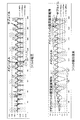
図11~図13に、図8,図9の構成の発電機について試作および磁場解析を行った結果を示す。
図11は、磁場解析によるコイル電圧、鎖交磁束の立ち上がり波形を示す。同図から、メインコイルの鎖交磁束が徐々に増加していく状態が分かる。なお、同図における「メインコイル」は、実施形態で言う「主界磁巻線9」に相当し、「サブコイル」は実施形態で言う「副界磁巻線10」に相当する。また、「ロータコイル」は「出力巻線7」に相当する。図12,図13から、ロータ5の回転による各部の磁束密度の変化が分かる。
図11は、磁場解析によるコイル電圧、鎖交磁束の立ち上がり波形を示す。同図から、メインコイルの鎖交磁束が徐々に増加していく状態が分かる。なお、同図における「メインコイル」は、実施形態で言う「主界磁巻線9」に相当し、「サブコイル」は実施形態で言う「副界磁巻線10」に相当する。また、「ロータコイル」は「出力巻線7」に相当する。図12,図13から、ロータ5の回転による各部の磁束密度の変化が分かる。
1…発電機本体
2…着磁手段(初期励磁手段)
3…外部負荷
4…ステータ
5…ロータ
6…出力鉄心
6a…ヨーク部
6b…磁極部
7…出力巻線
8…界磁鉄心
8a…鉄心本体
8b…磁極部
9…主界磁巻線
10…副界磁巻線
11…第1整流素子
12…第2整流素子
13…スイッチング素子
14…着磁用電源
15…開閉制御手段
16…回転検出手段
31…初期励磁用磁石(初期励磁手段)
G…発電機
W…風力発電装置
2…着磁手段(初期励磁手段)
3…外部負荷
4…ステータ
5…ロータ
6…出力鉄心
6a…ヨーク部
6b…磁極部
7…出力巻線
8…界磁鉄心
8a…鉄心本体
8b…磁極部
9…主界磁巻線
10…副界磁巻線
11…第1整流素子
12…第2整流素子
13…スイッチング素子
14…着磁用電源
15…開閉制御手段
16…回転検出手段
31…初期励磁用磁石(初期励磁手段)
G…発電機
W…風力発電装置
Claims (11)
- 出力巻線が巻かれた出力鉄心と、
主界磁巻線および副界磁巻線が巻かれた界磁鉄心と、
を備え、
前記出力鉄心および前記界磁鉄心のいずれか一方がステータとなり、他方がロータとなり、前記主界磁巻線に第1整流素子が接続され、前記副界磁巻線に第2整流素子が接続され、前記ステータとロータとの相対回転により発電電力を得る自励式の発電機であって、
発電の初期励磁に必要な程度に、前記出力鉄心および界磁鉄心のいずれか一方または両方に磁力を付与する初期励磁手段を設けた発電機。 - 請求項1に記載の発電機において、前記初期励磁手段が、発電の初期励磁に必要な磁力を発生することが可能な程度に、前記出力鉄心および界磁鉄心のいずれか一方または両方を着磁する着磁手段である発電機。
- 請求項2に記載の発電機において、前記着磁手段は、前記出力巻線、前記主界磁巻線および前記副界磁巻線のいずれかに着磁用電流を通電する構成である発電機。
- 請求項3に記載の発電機において、前記着磁用電流は直流電流である発電機。
- 請求項3に記載の発電機において、前記着磁用電流はパルス状の電流である発電機。
- 請求項3から5のいずれか一項に記載の発電機において、前記着磁手段は、
2次電池またはコンデンサからなる着磁用電源と、
前記着磁用電流を通電する前記出力巻線と前記着磁用電源との間、または前記主界磁巻線および前記副界磁巻線と前記着磁用電源との間に介在させたスイッチング素子と、
でなる発電機。 - 請求項1に記載の発電機において、前記初期励磁手段が、前記界磁鉄心に設けられて発電の初期励磁に必要な磁力を発生する永久磁石からなる初期励磁用磁石である発電機。
- 請求項7に記載の発電機において、前記界磁鉄心の磁極における、前記出力鉄心と対向する面に前記初期励磁用磁石を埋め込んだ発電機。
- 請求項7に記載の発電機において、前記界磁鉄心における隣合う磁極部の間に前記初期励磁用磁石を埋め込んだ発電機。
- 請求項7から9のいずれか一項に記載の発電機において、前記界磁鉄心に設けた前記初期励磁用磁石の発生する磁束の向きは、前記主界磁巻線に流れる励磁電流がつくる磁束の向きと同じである発電機。
- 請求項1から10のいずれか一項に記載の発電機において、前記ロータが風車によって回転駆動される風力発電用発電機として構成されている発電機。
Priority Applications (3)
| Application Number | Priority Date | Filing Date | Title |
|---|---|---|---|
| CN201580039574.2A CN106537758A (zh) | 2014-07-24 | 2015-07-16 | 发电机 |
| EP15825372.4A EP3174194A4 (en) | 2014-07-24 | 2015-07-16 | Generator |
| US15/412,677 US20170133916A1 (en) | 2014-07-24 | 2017-01-23 | Generator |
Applications Claiming Priority (6)
| Application Number | Priority Date | Filing Date | Title |
|---|---|---|---|
| JP2014150684A JP2016025815A (ja) | 2014-07-24 | 2014-07-24 | 発電機 |
| JP2014-150442 | 2014-07-24 | ||
| JP2014-150684 | 2014-07-24 | ||
| JP2014150442A JP2016025811A (ja) | 2014-07-24 | 2014-07-24 | 発電機 |
| JP2014163438A JP2016039747A (ja) | 2014-08-11 | 2014-08-11 | 風力発電用発電機 |
| JP2014-163438 | 2014-08-11 |
Related Child Applications (1)
| Application Number | Title | Priority Date | Filing Date |
|---|---|---|---|
| US15/412,677 Continuation US20170133916A1 (en) | 2014-07-24 | 2017-01-23 | Generator |
Publications (1)
| Publication Number | Publication Date |
|---|---|
| WO2016013477A1 true WO2016013477A1 (ja) | 2016-01-28 |
Family
ID=55163003
Family Applications (1)
| Application Number | Title | Priority Date | Filing Date |
|---|---|---|---|
| PCT/JP2015/070375 WO2016013477A1 (ja) | 2014-07-24 | 2015-07-16 | 発電機 |
Country Status (4)
| Country | Link |
|---|---|
| US (1) | US20170133916A1 (ja) |
| EP (1) | EP3174194A4 (ja) |
| CN (1) | CN106537758A (ja) |
| WO (1) | WO2016013477A1 (ja) |
Families Citing this family (2)
| Publication number | Priority date | Publication date | Assignee | Title |
|---|---|---|---|---|
| US11336134B2 (en) * | 2016-10-04 | 2022-05-17 | Holcomb Scientific Research Limited | Solid state multi-pole and uni-pole electric generator rotor for AC/DC electric generators |
| CN110729829B (zh) * | 2019-10-23 | 2020-12-04 | 温岭绿能新能源有限公司 | 发电机的磁阻调整方法 |
Citations (4)
| Publication number | Priority date | Publication date | Assignee | Title |
|---|---|---|---|---|
| JPS50106122A (ja) * | 1973-08-03 | 1975-08-21 | ||
| JPS54140113A (en) * | 1978-04-24 | 1979-10-31 | Nippon Denso Co Ltd | Self excited alternating current generator |
| JPS6181771U (ja) * | 1984-10-31 | 1986-05-30 | ||
| JPH0716000A (ja) * | 1993-06-22 | 1995-01-17 | Hitachi Ltd | 不平衡負荷補償発電システム |
Family Cites Families (17)
| Publication number | Priority date | Publication date | Assignee | Title |
|---|---|---|---|---|
| GB757304A (en) * | 1951-09-24 | 1956-09-19 | Macfarlane Engineering Company | Improvements in electric generators |
| FR1399717A (fr) * | 1964-04-09 | 1965-05-21 | Bronzavia Sa | Procédé et dispositif pour la commande et la régulation de la tension nominale d'un alternateur asynchrone |
| CH546509A (de) * | 1972-06-26 | 1974-02-28 | Bbc Brown Boveri & Cie | Elektronische schaltungsanordnung zur erregung eines asynchron anlaufenden, schleifringlosen synchronmotors. |
| DE2650851A1 (de) * | 1976-11-06 | 1978-05-11 | Bosch Gmbh Robert | Stromversorgungseinrichtung fuer eine zweispannungsanlage in einem kraftfahrzeug |
| DE2920101A1 (de) * | 1979-05-18 | 1980-11-27 | Bosch Gmbh Robert | Vorrichtung zur erregung von drehstromgeneratoren |
| SU868937A1 (ru) * | 1980-01-24 | 1981-09-30 | Предприятие П/Я А-7376 | Самовозбуждающийс двухчастотный генератор |
| US4499530A (en) * | 1981-09-30 | 1985-02-12 | Hitachi, Ltd. | Switching power supply apparatus |
| JPS6135126A (ja) * | 1984-07-24 | 1986-02-19 | 株式会社日立製作所 | 発電機の制御装置 |
| JPH01264551A (ja) * | 1988-04-12 | 1989-10-20 | Shindaiwa Kogyo Kk | ブラシレス自励同期発電機 |
| JP3165968B2 (ja) * | 1991-05-22 | 2001-05-14 | 新ダイワ工業株式会社 | ブラシレス同期機 |
| JPH077900A (ja) * | 1993-05-24 | 1995-01-10 | Tadashi Fukami | ブラシレス三相同期発電機 |
| US6586914B2 (en) * | 2001-11-19 | 2003-07-01 | General Electric Company | Wound field synchronous machine control system and method |
| WO2007032233A1 (ja) * | 2005-09-15 | 2007-03-22 | Murata Manufacturing Co., Ltd. | 同期整流型フォワードコンバータ |
| CN1770581A (zh) * | 2005-10-11 | 2006-05-10 | 横店得邦电子有限公司 | 一种单路综合保护电路 |
| WO2007046195A1 (ja) * | 2005-10-19 | 2007-04-26 | Murata Manufacturing Co., Ltd. | 同期整流型フォワードコンバータ |
| CN102340224A (zh) * | 2011-06-30 | 2012-02-01 | 无锡星诺电气有限公司 | 5kw发电电焊机的自励装置 |
| US9252695B2 (en) * | 2014-03-12 | 2016-02-02 | General Electric Company | Brushless permanent magnet generator plus auxiliary voltage source constant potential exciter |
-
2015
- 2015-07-16 EP EP15825372.4A patent/EP3174194A4/en not_active Withdrawn
- 2015-07-16 WO PCT/JP2015/070375 patent/WO2016013477A1/ja active Application Filing
- 2015-07-16 CN CN201580039574.2A patent/CN106537758A/zh active Pending
-
2017
- 2017-01-23 US US15/412,677 patent/US20170133916A1/en not_active Abandoned
Patent Citations (4)
| Publication number | Priority date | Publication date | Assignee | Title |
|---|---|---|---|---|
| JPS50106122A (ja) * | 1973-08-03 | 1975-08-21 | ||
| JPS54140113A (en) * | 1978-04-24 | 1979-10-31 | Nippon Denso Co Ltd | Self excited alternating current generator |
| JPS6181771U (ja) * | 1984-10-31 | 1986-05-30 | ||
| JPH0716000A (ja) * | 1993-06-22 | 1995-01-17 | Hitachi Ltd | 不平衡負荷補償発電システム |
Non-Patent Citations (1)
| Title |
|---|
| See also references of EP3174194A4 * |
Also Published As
| Publication number | Publication date |
|---|---|
| EP3174194A4 (en) | 2018-02-28 |
| US20170133916A1 (en) | 2017-05-11 |
| EP3174194A1 (en) | 2017-05-31 |
| CN106537758A (zh) | 2017-03-22 |
Similar Documents
| Publication | Publication Date | Title |
|---|---|---|
| JP5216686B2 (ja) | 永久磁石形発電機 | |
| JP6541145B2 (ja) | 低温用フェライト磁石モーターを加熱するためのシステムおよび方法 | |
| JP2013055789A (ja) | 電動発電機 | |
| CN107196477B (zh) | 旋转电机 | |
| US8569921B2 (en) | Permanent-magnet type electric rotating machine | |
| WO2016013477A1 (ja) | 発電機 | |
| KR101238855B1 (ko) | 이중 공극형 발전기 | |
| JP2015511811A (ja) | 磁気移転によって励磁される電力モータ発電機 | |
| CN106787547B (zh) | 一种轴向磁通两相双凸极永磁电机 | |
| KR100664091B1 (ko) | 자기 착자 모터 및 그 자기 착자 모터의 고정자 권선 방법 | |
| JP2016025811A (ja) | 発電機 | |
| JP2016169711A (ja) | 風力発電用の風車および風力発電機 | |
| WO2019098341A1 (ja) | ブラシレス同期発電機 | |
| JP2016039747A (ja) | 風力発電用発電機 | |
| EP1798844B1 (en) | Self magnetizing motor | |
| JP2016025815A (ja) | 発電機 | |
| JP6444677B2 (ja) | 発電機 | |
| DK181215B1 (en) | System adapted for operating generator | |
| JP6396146B2 (ja) | 発電機 | |
| JP2016067128A (ja) | 発電機 | |
| JP6444676B2 (ja) | 発電機 | |
| US8922154B2 (en) | Brushless starter-generator assembly and method to control magnetic flux excitation | |
| JP6343702B1 (ja) | 風力発電機 | |
| JP2016140216A (ja) | 発電機 | |
| JP2008278716A (ja) | 風力発電装置 |
Legal Events
| Date | Code | Title | Description |
|---|---|---|---|
| 121 | Ep: the epo has been informed by wipo that ep was designated in this application |
Ref document number: 15825372 Country of ref document: EP Kind code of ref document: A1 |
|
| REEP | Request for entry into the european phase |
Ref document number: 2015825372 Country of ref document: EP |
|
| WWE | Wipo information: entry into national phase |
Ref document number: 2015825372 Country of ref document: EP |
|
| NENP | Non-entry into the national phase |
Ref country code: DE |