WO2016013186A1 - 鋼の連続鋳造方法 - Google Patents
鋼の連続鋳造方法 Download PDFInfo
- Publication number
- WO2016013186A1 WO2016013186A1 PCT/JP2015/003602 JP2015003602W WO2016013186A1 WO 2016013186 A1 WO2016013186 A1 WO 2016013186A1 JP 2015003602 W JP2015003602 W JP 2015003602W WO 2016013186 A1 WO2016013186 A1 WO 2016013186A1
- Authority
- WO
- WIPO (PCT)
- Prior art keywords
- slab
- mold
- corner
- casting
- length
- Prior art date
- Legal status (The legal status is an assumption and is not a legal conclusion. Google has not performed a legal analysis and makes no representation as to the accuracy of the status listed.)
- Ceased
Links
Images



Classifications
-
- B—PERFORMING OPERATIONS; TRANSPORTING
- B22—CASTING; POWDER METALLURGY
- B22D—CASTING OF METALS; CASTING OF OTHER SUBSTANCES BY THE SAME PROCESSES OR DEVICES
- B22D11/00—Continuous casting of metals, i.e. casting in indefinite lengths
- B22D11/04—Continuous casting of metals, i.e. casting in indefinite lengths into open-ended moulds
-
- B—PERFORMING OPERATIONS; TRANSPORTING
- B22—CASTING; POWDER METALLURGY
- B22D—CASTING OF METALS; CASTING OF OTHER SUBSTANCES BY THE SAME PROCESSES OR DEVICES
- B22D11/00—Continuous casting of metals, i.e. casting in indefinite lengths
- B22D11/12—Accessories for subsequent treating or working cast stock in situ
- B22D11/124—Accessories for subsequent treating or working cast stock in situ for cooling
-
- B—PERFORMING OPERATIONS; TRANSPORTING
- B22—CASTING; POWDER METALLURGY
- B22D—CASTING OF METALS; CASTING OF OTHER SUBSTANCES BY THE SAME PROCESSES OR DEVICES
- B22D11/00—Continuous casting of metals, i.e. casting in indefinite lengths
- B22D11/16—Controlling or regulating processes or operations
- B22D11/22—Controlling or regulating processes or operations for cooling cast stock or mould
Definitions
- the present invention relates to a steel continuous casting method in which occurrence of surface cracks in a slab in continuous casting is suppressed.
- low alloy steels containing alloy elements such as Cu, Ni, Nb, V and Ti are applied particularly to thick steel plates.
- the corner portion perpendicular to the casting direction of the slab at the straightened portion or the bent portion of the slab Stress
- surface cracks particularly cracks at the corners are likely to occur. This corner crack is likely to cause a surface flaw of the thick steel plate, and causes a decrease in the yield of the steel plate product.
- the slab of low alloy steel has a marked decrease in hot ductility at a temperature in the vicinity of the Ar 3 transformation point where the solidification structure transforms from an austenite phase to a ferrite phase. Furthermore, in the slab of low alloy steel, AlN, NbC, etc. are precipitated at the austenite grain boundaries during the secondary cooling, and are easily embrittled. For this reason, cracks are likely to occur on the surface of the slab, especially on the corner portion where stress is applied.
- Patent Document 1 secondary cooling of a slab is started immediately after the slab is drawn out of a rectangular mold, and after the surface temperature of the slab is once cooled to a temperature lower than the Ar 3 transformation point, Ar 3
- the time required to maintain the slab surface temperature below the Ar 3 transformation point and the lowest temperature that the slab surface temperature can reach are appropriately set.
- Patent Document 2 discloses that when the solidified shell thickness is 10 mm or more and 15 mm or less, the primary cooling by the mold is finished and the secondary cooling is started, and the surface temperature of the entire surface of the slab is within 2 minutes from the exit of the mold. In the meantime, a technique is disclosed in which the temperature is once lowered to a range of 600 ° C. or higher and below the Ar 3 point, and secondary cooling is performed so that both the slab surface temperature in the bent portion and the slab surface temperature in the straightened portion become 850 ° C. or higher. ing.
- the present invention has been made in view of the above circumstances, and an object of the present invention is to form a surface crack of a slab, which has not been sufficiently solved only by controlling the slab structure by secondary cooling, in an appropriate shape.
- An object of the present invention is to provide a high-quality slab that is reliably suppressed by controlling the temperature of the slab corner portion by secondary cooling while using a mold having a casting space, and that is particularly free from corner cracks.
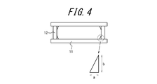
- the gist configuration of the present invention is as follows. (1) In a continuous casting method in which molten steel is charged into a mold and a slab is drawn directly from the mold, At the four corners of the rectangular space defined by the pair of mold long sides and the pair of mold short sides, the ratio b / a of the length b on the mold short side to the length a on the mold long side is 3.0 or more and 6.0. Using the casting mold, which has the casting space removed in the shape of a right triangle that becomes Before reaching the bending correction point from directly below the mold, the surface temperature of at least the corner portion of the slab is once lowered to Ar 3 point or less, and then at least the surface temperature of the corner portion is set to 800 ° C. or higher. A method for continuous casting of steel, wherein the bending correction point is passed at 800 ° C or higher.
- the length a on the long side of the mold is 4 to 6 mm, and the length b on the short side of the mold is 12 to 36 mm, as described in (1) or (2) above Steel continuous casting method.
- the temperature of the slab corner portion is controlled by secondary cooling, thereby preventing corner cracking of the continuous cast slab, and high quality slab Can be provided.
- the continuous casting method of the present invention will be described in detail with reference to the drawings.
- the molten steel is continuously cast using a vertical bending type continuous casting machine as shown in FIG. 1, for example, but at this time, surface cracks are not induced at the corner of the slab, particularly during straightening at a bending straightening point. Therefore, it is important to use a mold in which a casting space of an appropriate shape is partitioned and to pass an appropriate cooling pattern in a cooling zone immediately below the mold.
- reference numeral 1 denotes molten steel charged in the ladle 2.
- the molten steel 1 is supplied into a water-cooled mold 6 from a ladle 2 through a long nozzle 3, a tundish 4 and an immersion nozzle 5.
- the molten steel 1 cooled by the water-cooled mold 6 is guided to the outlet side of the mold 6 while forming a solidified shell, and is pulled out of the mold 6, and further cooled in the secondary cooling zone 7 immediately below the mold 6 to be solidified. Promoted shell growth.
- the slab On the exit side of the secondary cooling zone 7, the slab is forced to bend and guided in the horizontal direction, and then the bending is corrected in the drawing straightening zone (bending portion) 8 to form the continuous casting slab 9.
- the inventors observed surface cracks on the slab cast by the vertical bending type continuous casting machine shown in FIG.
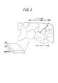
- the cracks of the slab are concentrated at the lower surface corner and the vicinity thereof (see FIG. 2).
- the lower surface side of a slab means the outer side of the bending of the curved belt of a vertical bending continuous casting machine, ie, the long side surface side which becomes a lower surface in a horizontal belt.
- the vertical bending type continuous casting machine is a casting machine having a short vertical part length of, for example, about 3.5 m before entering the bending part.
- the slab was made chamfered by removing the corners of the four corners of the rectangular cross section perpendicular to the casting direction, thereby reducing the stress load at the corner of the slab. It was found that it can be reduced.
- a mold having a casting space having such a chamfered shape is also referred to as a chamfer mold.
- Patent Document 3 describes providing corner drop portions at four corners.
- the technique described in Patent Document 3 aims to normalize the growth of the solidified shell at the corner portion of the slab and prevent defects in the slab due to the solidification delay of the corner portion. Therefore, it is unclear whether the shape of the chamfer described in Patent Document 3 is suitable for preventing the surface crack of the slab as expected in the present invention. That is, in the technique described in Patent Document 3, the solidification of the corner portion of the rectangular cross-section mold is easier to proceed than the other portions in the initial stage of solidification of the steel, and the solidification shell and the rectangular corner portion of the mold are separated by solidification shrinkage.
- the stress load on the corner portion of the slab is first reduced by using the chamfer mold as compared with the rectangular mold.
- the ratio b / a is in the range of 3 to 6
- the stress load at the corner of the slab tends to be reduced.
- the stress load at the slab corner portion becomes smaller as the length a on the mold long side 1 side is smaller.
- the surface temperature of the corner of the slab is temporarily changed to the Ar 3 point until the slab enters the bending part.
- the surface temperature of the slab corner is set to 800 ° C. or higher and the secondary cooling is performed at a temperature of 800 ° C. or higher before the bending portion is entered.
- a mold with / a of 3 to 6 was used, surface cracks at the corners of the slab could be reliably suppressed.
- the temperature is 800 ° C. or higher before entering the bent portion. In the case where the bending temperature does not reach 800 ° C., a large amount of prior austenite grain boundaries remain in the solidified structure, so that the rate of occurrence of corner cracks cannot be sufficiently reduced.
- the ratio b / a in the mold is preferably more than 4. This is because when the ratio b / a is 4 or less, as shown in FIG. 5, the stress load applied to the corner portion is slightly higher than when b / a is greater than 4 to 6, Because.
- the length a on the long side of the mold is preferably 4 to 6 mm and the length b on the short side of the mold is preferably 12 to 36 mm. This is because, as shown in FIG. 5, the stress load applied to the corner tends to decrease as the length a on the long side decreases, and the length a on the long side is 7 mm. This is because the stress load tends to be slightly larger than the case.
- a low alloy steel having a composition shown in Table 1 and having high cracking sensitivity was cast by a vertical bending type continuous casting machine.
- the Ar 3 transformation point of this steel is 725 ° C.
- the casting conditions were a casting thickness of 220 to 300 mm, a casting width of 1400 to 2100 mm, and a casting speed of 0.60 to 2.50 m / min.
- molds having various chamfered shapes shown in Table 2 were manufactured and used.
- continuous casting using a rectangular mold was performed under the same casting conditions. The amount of secondary cooling water was changed according to the casting thickness, casting width, and casting speed, but the surface temperature of the slab corner was once lowered below the Ar 3 transformation point before entering the bending part, and then bent.
- the heat was reheated before entering the part, adjusted to 800 ° C. or higher, and adjusted using heat transfer analysis so that the bent part passed at 800 ° C. or higher.
- casting was also performed in which the temperature at the corner of the slab did not satisfy the conditions of the present invention.
- the slab temperature at the time of a bending part passage was confirmed by measuring using a thermocouple and a radiation thermometer.
- the cast slab is removed by shot blasting to remove the oxide on the surface of the slab, and then a color check (dye penetrant flaw detection test) is performed. The presence or absence of cracks was investigated.
- Comparative Examples 1 and 2 are examples in which a rectangular mold was used, and the slab corner temperature was manufactured under conditions that did not satisfy the present invention. In this case, the crack occurrence rate at the corner was as high as 9.4 to 10.8%. When these solidification structures were observed, the prior austenite grain boundaries as shown in FIG. 2 were clear structures.
- Comparative Examples 3 and 4 use a rectangular mold, and the slab corner temperature is a condition that satisfies the present invention. In this case, the corner crack occurrence rate was 4.7 to 5.2%, which was lower than that of Comparative Examples 1 and 2, but was a level that required further improvement. As shown in FIG. 3, these solidified structures were structures in which some prior austenite grain boundaries remained.
- Comparative Examples 5 to 12 use a chamfer mold, and the slab corner temperature is a condition that does not satisfy the present invention. Also in this case, the corner crack occurrence rate was 5.3-7.3%, which was a level that needed improvement. These solidified structures were also structures with clear prior austenite grain boundaries as shown in FIG. In Comparative Examples 13 to 15, a chamfer mold is used, and the casting corner temperature is also a condition that satisfies the present invention. However, with respect to the shape of the chamfer portion, the ratio b / a of the length a on the long side and the length b on the short side is a condition that does not satisfy the present invention. Also in this case, the corner crack occurrence rate was 3.8 to 4.5%, which was a level that needed improvement.
- Invention Examples 1 to 8 are conditions in which a chamfer mold is used and the secondary cooling spray is adjusted so that the slab corner temperature satisfies the present invention.
- the incidence of corner cracks was as good as 1.4% or less.
- the former austenite grain boundaries remained in a part as shown in FIG. 3 and were the same solidified structures as in Comparative Examples 3 and 4. That is, it was confirmed that corner cracking can be prevented by using a chamfer mold even if the solidified structure is partially incomplete.
- the length a on the long side of the mold is 4 to 7 mm, and the ratio b / a to the length b on the short side of the mold is 3.0 to 6.0.
- a mold in which the length b on the short side of the mold was changed as shown in Table 3 was used.
- production of the corner part crack was evaluated similarly to the case of Example 1.
- FIG. The results are also shown in Table 3.
- a preferred embodiment of the present invention is that the mold long side length a is 4 to 6 mm and b / a is 3 to 6, more preferably more than 4 to 6. At that time, the mold short side length b is 12 to 36 mm, more preferably more than 16 mm to 36 mm.
- the mold long side length a is less than 4 mm, severe processing accuracy is required at the four corners of the mold. Therefore, in actual operation, it is preferably 4 mm or more.
- the chamfered portion can be formed by, for example, machining a solid copper plate.
Landscapes
- Engineering & Computer Science (AREA)
- Mechanical Engineering (AREA)
- Continuous Casting (AREA)
Abstract
Description
即ち、特許文献1及び特許文献2に記載の技術では、2次冷却スプレーから鋳片に噴射された後に鋳片を伝って流れる、垂れ水の影響が懸念される。とりわけ、鋳造速度が遅くなると、垂れ水が鋳片表面の冷却に影響して、例えば伝熱解析等により鋳片表面温度を定量的に制御することが困難になる場合があった。
(1)溶鋼を鋳型に装入し、該鋳型から直接鋳片を引き抜く連続鋳造方法において、
一対の鋳型長辺と一対の鋳型短辺とで区画される矩形空間の四隅を、前記鋳型長辺側の長さaに対する前記鋳型短辺側の長さbの比b/aが3.0以上6.0以下となる直角三角形状に取り除いた鋳造空間を有する、鋳型を用いて、
前記鋳型の直下から曲げ矯正点に至る前において、前記鋳片の少なくともコーナー部の表面温度を、一旦Ar3点以下まで低下し、次いで、少なくとも該コーナー部の表面温度を800℃以上にしてから前記曲げ矯正点を800℃以上で通過させることを特徴とする鋼の連続鋳造方法。
さて、溶鋼は、例えば図1に示すような、垂直曲げ型の連続鋳造機を用いて連続鋳造されるが、その際、特に曲げ矯正点での矯正時に鋳片コーナー部で表面割れを誘発させないために、適切な形状の鋳造空間が区画された鋳型を用いるとともに、鋳型直下の冷却帯において適切な冷却パターンを経ることが肝要である。
しかしながら、依然として、いくつかの鋳片では相変わらず下面側にコーナー割れが残存しており、これらコーナー割れの周囲の凝固組織を観察すると、図3に模式で示すように、鋳片表層は旧オーステナイト粒界の不明瞭なフェライト-パーライトの混合組織が得られつつあるものの、旧オーステナイト粒界も一部に残存している。そして、コーナー割れは、残存している旧オーステナイト粒界に沿って発生していることが判明した。
また、一般に、垂直曲げ型連続鋳造機は、曲げ部に入るまでの垂直部長さが例えば3.5m程度と短い鋳造機である。かように、曲げ部に入るまでの距離が短い連続鋳造機では、一旦Ar3点以下に温度を低下させる際に、垂れ水等の影響で過度に鋳片が冷却されると、その後、曲げ部に入るまでの間に復熱させるための時間を稼ぐことが難しく、凝固組織が不完全となることも想定される。
ここで、発明者らは、鋳片コーナー部への応力負荷に着目した。すなわち、図3に示したように、2次冷却条件を規制することで凝固組織は改善され、コーナー部割れの程度も図2と比較すると軽微なものとなるため、2次冷却条件に加えて、曲げ・矯正時にコーナー部にかかる応力を低減できれば、コーナー割れの発生を防止できる可能性があると考えた。
なお、比b/aが3~6の鋳型を用いても、鋳片コーナー部の表面温度がAr3点以下まで低下していない場合、曲げ部に入るまでの間に800℃以上になっていない場合、そして曲げ部の通過温度が800℃に至らない場合には、凝固組織に旧オーステナイト粒界が多く残存してしまうため、コーナー割れ発生率を十分に低減することはできない。
2次冷却水量は鋳造厚み、鋳造幅、鋳造速度に応じて変化させたが、鋳片コーナー部の表面温度を、曲げ部に入るまでに一旦、Ar3変態点以下に低下させ、その後、曲げ部に入るまでの間に復熱させて800℃以上にして曲げ部を800℃以上で通過するように伝熱解析を用いて調整した。比較として、鋳片コーナー部の温度が本発明の条件を満たさない鋳造も実施した。
なお、曲げ部通過時の鋳片温度は、熱電対や放射温度計を用いて測定することで確認した。鋳造後の鋳片は、鋳片表面の割れの観察を容易にするために、ショットブラストにより鋳片表面の酸化物を除去し、その後、カラーチェック(染色浸透探傷試験)を行って、コーナー部の割れ有無を調査した。そして、コーナー割れ発生率として、コーナー割れ鋳片本数/調査鋳片本数×100%で評価した。また、鋳片コーナー部から30mm角の凝固組織観察用サンプルを切り出し、観察面を研磨後、3%ナイタール腐食を行い、光学顕微鏡により凝固組織を観察した。

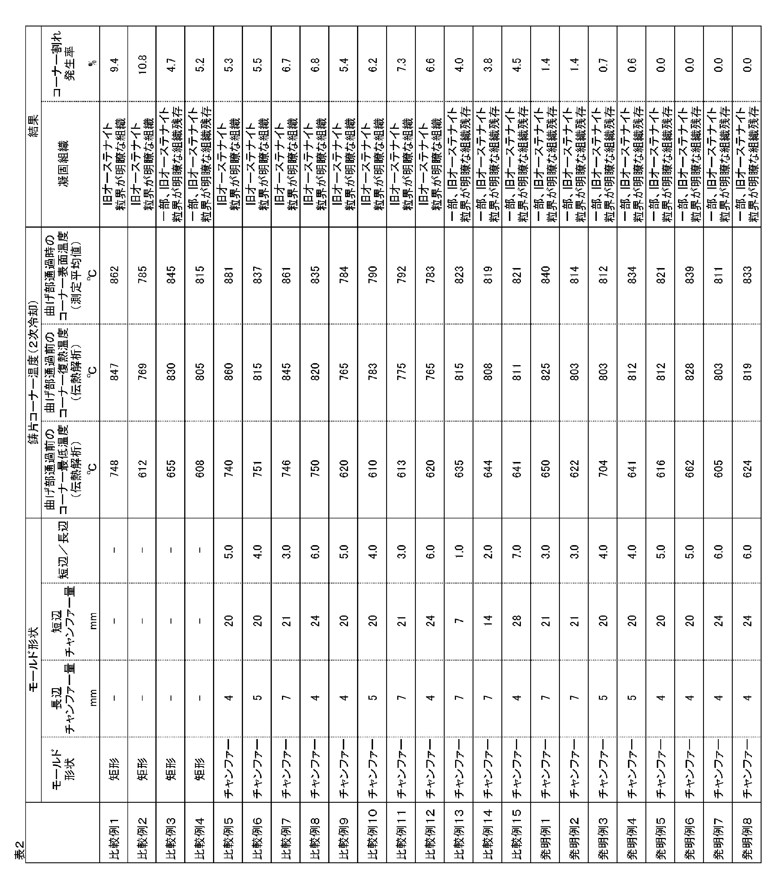
比較例13~15は、チャンファーモールドを用い、鋳辺コーナー温度も本発明を満たす条件である。但し、チャンファー部の形状について、長辺側の長さaと短辺側の長さbの比b/aは本発明を満たさない条件である。この場合も、コーナー割れ発生率は3.8~4.5%となり、改善が必要なレベルであった。
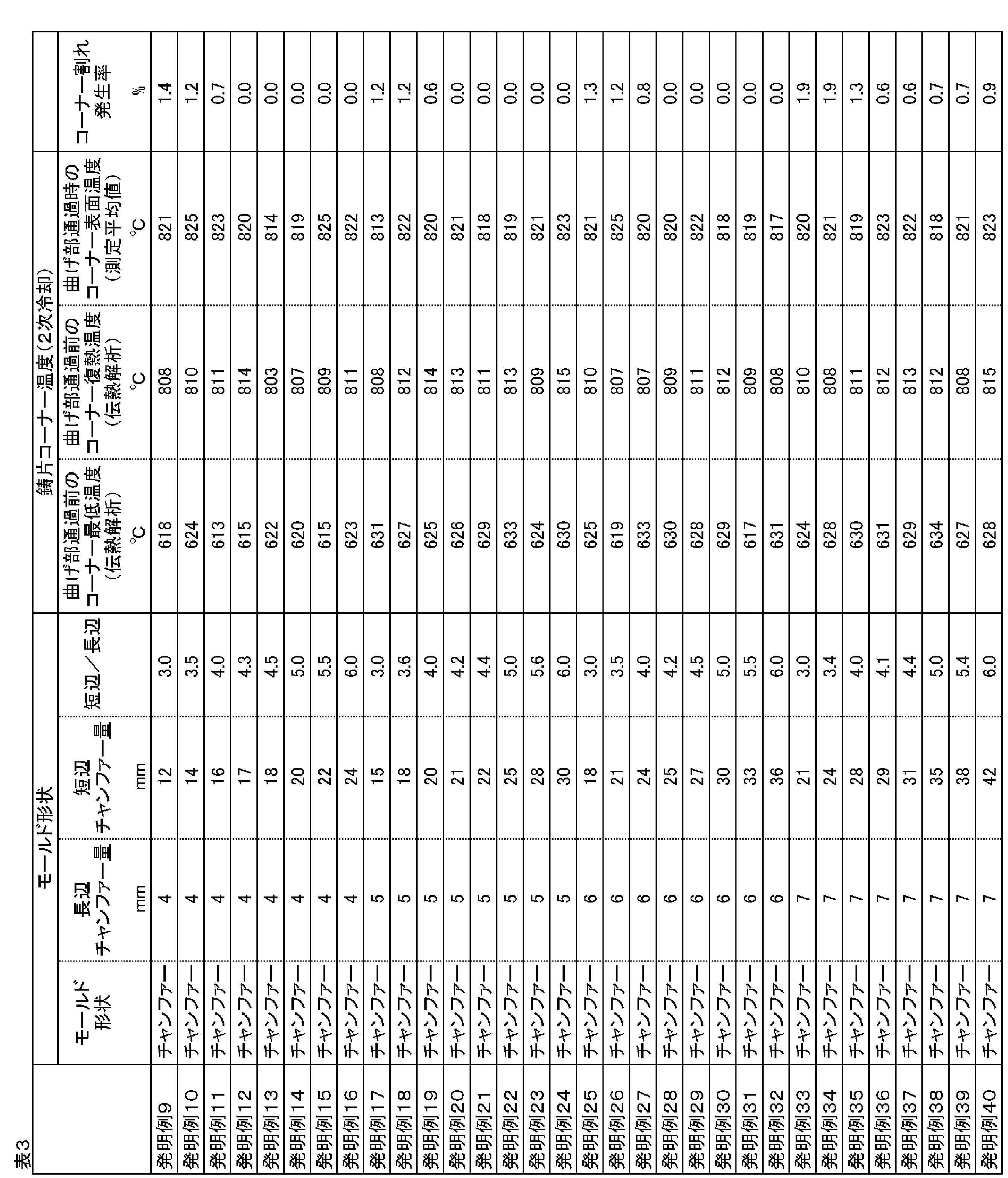
すなわち、鋳型長辺側長さaを4~6mmとし、b/aを3~6、より好ましくは4超~6の範囲とするのが本発明の好適例であることが分かる。その際、鋳型短辺側長さbは12~36mmとなり、より好ましくは16mm超~36mmの範囲となる。
なお、鋳型長辺側長さaが4mmを下回る場合は、鋳型の四隅において厳しい加工精度が求められるから、実操業においては4mm以上とすることが好ましい。ちなみに、面取り部は、例えば無垢の銅板に削り出し加工を施すことによって成形することができる。
2 取鍋
3 ロングノズル
4 タンディッシュ
5 浸漬ノズル
6 水冷鋳型
7 2次冷却帯
8 引き抜き矯正帯(曲げ部)
9 連続鋳造鋳片
11 鋳型長辺
12 鋳型短辺
Claims (3)
- 溶鋼を鋳型に装入し、該鋳型から直接鋳片を引き抜く連続鋳造方法において、
一対の鋳型長辺と一対の鋳型短辺とで区画される矩形空間の四隅を、前記鋳型長辺側の長さaに対する前記鋳型短辺側の長さbの比b/aが3.0以上6.0以下となる直角三角形状に取り除いた鋳造空間を有する、鋳型を用いて、
前記鋳型の直下から曲げ矯正点に至る前において、前記鋳片の少なくともコーナー部の表面温度を、一旦Ar3点以下まで低下し、次いで、少なくとも該コーナー部の表面温度を800℃以上にしてから前記曲げ矯正点を800℃以上で通過させることを特徴とする鋼の連続鋳造方法。 - 前記比b/aが4.0超である請求項1に記載の鋼の連続鋳造方法。
- 前記鋳型長辺側の長さaが4~6mmおよび、前記鋳型短辺側の長さbが12~36mmであることを特徴とする、請求項1または2に記載の鋼の連続鋳造方法。
Priority Applications (3)
| Application Number | Priority Date | Filing Date | Title |
|---|---|---|---|
| CN201580039666.0A CN106536085B (zh) | 2014-07-24 | 2015-07-16 | 钢的连续铸造方法 |
| JP2016535783A JP5999294B2 (ja) | 2014-07-24 | 2015-07-16 | 鋼の連続鋳造方法 |
| KR1020167034572A KR101889208B1 (ko) | 2014-07-24 | 2015-07-16 | 강의 연속 주조 방법 |
Applications Claiming Priority (2)
| Application Number | Priority Date | Filing Date | Title |
|---|---|---|---|
| JP2014150925 | 2014-07-24 | ||
| JP2014-150925 | 2014-07-24 |
Publications (1)
| Publication Number | Publication Date |
|---|---|
| WO2016013186A1 true WO2016013186A1 (ja) | 2016-01-28 |
Family
ID=55162731
Family Applications (1)
| Application Number | Title | Priority Date | Filing Date |
|---|---|---|---|
| PCT/JP2015/003602 Ceased WO2016013186A1 (ja) | 2014-07-24 | 2015-07-16 | 鋼の連続鋳造方法 |
Country Status (5)
| Country | Link |
|---|---|
| JP (1) | JP5999294B2 (ja) |
| KR (1) | KR101889208B1 (ja) |
| CN (1) | CN106536085B (ja) |
| TW (1) | TWI569907B (ja) |
| WO (1) | WO2016013186A1 (ja) |
Cited By (4)
| Publication number | Priority date | Publication date | Assignee | Title |
|---|---|---|---|---|
| US10118218B2 (en) * | 2015-01-15 | 2018-11-06 | Nippon Steel & Sumitomo Metal Corporation | Method for continuously casting slab |
| JP2020171954A (ja) * | 2019-04-12 | 2020-10-22 | 日本製鉄株式会社 | 鋼の連続鋳造方法 |
| JP2022065814A (ja) * | 2020-10-16 | 2022-04-28 | 日本製鉄株式会社 | 連続鋳造用鋳型及び鋼の連続鋳造方法 |
| JP2022174996A (ja) * | 2021-05-12 | 2022-11-25 | 日本製鉄株式会社 | 鋼の連続鋳造方法及び連続鋳造用鋳型 |
Families Citing this family (3)
| Publication number | Priority date | Publication date | Assignee | Title |
|---|---|---|---|---|
| JP7188187B2 (ja) * | 2019-02-28 | 2022-12-13 | Jfeスチール株式会社 | 鋳片の冷却方法 |
| JP7060164B2 (ja) * | 2019-07-11 | 2022-04-26 | Jfeスチール株式会社 | 連続鋳造鋳片の2次冷却方法及び装置 |
| EP4170054A4 (en) * | 2020-06-18 | 2023-06-21 | JFE Steel Corporation | CONTINUOUS CASTING PROCESS |
Citations (4)
| Publication number | Priority date | Publication date | Assignee | Title |
|---|---|---|---|---|
| JPS58224055A (ja) * | 1982-06-23 | 1983-12-26 | Nippon Steel Corp | 連続鋳造鋳片の表面割れ防止方法 |
| JPH11197809A (ja) * | 1998-01-09 | 1999-07-27 | Sumitomo Metal Ind Ltd | 連続鋳造鋳片の表面割れ防止方法 |
| CN102642000A (zh) * | 2012-05-08 | 2012-08-22 | 首钢总公司 | 有效控制角部纵裂纹的板坯连铸倒角结晶器窄面铜板 |
| WO2013100499A1 (ko) * | 2011-12-27 | 2013-07-04 | 주식회사 포스코 | 연속주조 주형 |
Family Cites Families (13)
| Publication number | Priority date | Publication date | Assignee | Title |
|---|---|---|---|---|
| JPH0358079A (ja) | 1989-07-27 | 1991-03-13 | Nec Corp | ラベル |
| JP3058079B2 (ja) * | 1996-02-23 | 2000-07-04 | 住友金属工業株式会社 | 鋼の連続鋳造方法 |
| CZ289354B6 (cs) * | 1997-10-01 | 2002-01-16 | Concast Standard Ag | Kokilová trubka pro kokilu pro kontinuální lití ocelí, zejména peritektických ocelí |
| TW555601B (en) * | 1999-04-22 | 2003-10-01 | Europa Metalli Spa | Ingot mold for continuous casting of molten metal, particularly for forming rectangular- or square-section steel billets |
| DE10051489A1 (de) * | 2000-10-17 | 2002-04-18 | Sms Demag Ag | Plattenkokille zum Stranggießen von Metall, insbesondere von Stahl |
| JP3702807B2 (ja) | 2001-04-11 | 2005-10-05 | 住友金属工業株式会社 | 連続鋳造方法 |
| ES2304578T3 (es) * | 2004-12-29 | 2008-10-16 | Concast Ag | Instalacion de colada continua de acero para formatos de palanquillas y desbastes. |
| JP4864559B2 (ja) | 2006-06-15 | 2012-02-01 | 株式会社神戸製鋼所 | 連続鋳造用鋳型 |
| CN201677013U (zh) * | 2010-05-19 | 2010-12-22 | 首钢总公司 | 一种板坯连铸结晶器 |
| CN201744629U (zh) * | 2010-05-27 | 2011-02-16 | 钢铁研究总院 | 一种连铸用组合结晶器的窄面铜板 |
| CN201871696U (zh) * | 2010-10-27 | 2011-06-22 | 钢铁研究总院 | 一种具有曲面结构的结晶器窄面铜板 |
| CN202715798U (zh) * | 2012-08-21 | 2013-02-06 | 钢铁研究总院 | 一种生产八角形连铸坯的结晶器铜管 |
| CN110264200B (zh) | 2019-05-29 | 2021-11-19 | 中国工商银行股份有限公司 | 区块链数据处理方法及装置 |
-
2015
- 2015-07-16 KR KR1020167034572A patent/KR101889208B1/ko active Active
- 2015-07-16 WO PCT/JP2015/003602 patent/WO2016013186A1/ja not_active Ceased
- 2015-07-16 JP JP2016535783A patent/JP5999294B2/ja active Active
- 2015-07-16 CN CN201580039666.0A patent/CN106536085B/zh active Active
- 2015-07-23 TW TW104123882A patent/TWI569907B/zh active
Patent Citations (4)
| Publication number | Priority date | Publication date | Assignee | Title |
|---|---|---|---|---|
| JPS58224055A (ja) * | 1982-06-23 | 1983-12-26 | Nippon Steel Corp | 連続鋳造鋳片の表面割れ防止方法 |
| JPH11197809A (ja) * | 1998-01-09 | 1999-07-27 | Sumitomo Metal Ind Ltd | 連続鋳造鋳片の表面割れ防止方法 |
| WO2013100499A1 (ko) * | 2011-12-27 | 2013-07-04 | 주식회사 포스코 | 연속주조 주형 |
| CN102642000A (zh) * | 2012-05-08 | 2012-08-22 | 首钢总公司 | 有效控制角部纵裂纹的板坯连铸倒角结晶器窄面铜板 |
Cited By (7)
| Publication number | Priority date | Publication date | Assignee | Title |
|---|---|---|---|---|
| US10118218B2 (en) * | 2015-01-15 | 2018-11-06 | Nippon Steel & Sumitomo Metal Corporation | Method for continuously casting slab |
| JP2020171954A (ja) * | 2019-04-12 | 2020-10-22 | 日本製鉄株式会社 | 鋼の連続鋳造方法 |
| JP7284394B2 (ja) | 2019-04-12 | 2023-05-31 | 日本製鉄株式会社 | 鋼の連続鋳造方法 |
| JP2022065814A (ja) * | 2020-10-16 | 2022-04-28 | 日本製鉄株式会社 | 連続鋳造用鋳型及び鋼の連続鋳造方法 |
| JP7560725B2 (ja) | 2020-10-16 | 2024-10-03 | 日本製鉄株式会社 | 連続鋳造用鋳型及び鋼の連続鋳造方法 |
| JP2022174996A (ja) * | 2021-05-12 | 2022-11-25 | 日本製鉄株式会社 | 鋼の連続鋳造方法及び連続鋳造用鋳型 |
| JP7695524B2 (ja) | 2021-05-12 | 2025-06-19 | 日本製鉄株式会社 | 鋼の連続鋳造方法及び連続鋳造用鋳型 |
Also Published As
| Publication number | Publication date |
|---|---|
| JP5999294B2 (ja) | 2016-09-28 |
| KR20170003669A (ko) | 2017-01-09 |
| TW201607642A (zh) | 2016-03-01 |
| TWI569907B (zh) | 2017-02-11 |
| JPWO2016013186A1 (ja) | 2017-04-27 |
| KR101889208B1 (ko) | 2018-08-16 |
| CN106536085B (zh) | 2019-04-19 |
| CN106536085A (zh) | 2017-03-22 |
Similar Documents
| Publication | Publication Date | Title |
|---|---|---|
| JP5999294B2 (ja) | 鋼の連続鋳造方法 | |
| JP6384679B2 (ja) | 熱延鋼板の製造方法 | |
| CN107206474B (zh) | 铸坯的连续铸造方法 | |
| JPWO2018043491A1 (ja) | 圧延h形鋼及びその製造方法 | |
| JP5928413B2 (ja) | 鋼の連続鋳造方法 | |
| KR20170046402A (ko) | 포정강의 슬라브 제조 방법 | |
| KR102723092B1 (ko) | 연속 주조 방법 | |
| JP3622687B2 (ja) | 鋼の連続鋳造方法 | |
| JP2002086252A (ja) | 連続鋳造方法 | |
| JP3702807B2 (ja) | 連続鋳造方法 | |
| KR101223107B1 (ko) | 마르텐사이트계 스테인리스 열연박판 제조장치 및 마르텐사이트계 스테인리스 열연박판의 제조방법 | |
| JP2007245232A (ja) | 連続鋳造鋳片の表面割れ防止方法 | |
| JP4561755B2 (ja) | B及びnを含有する鋼の連続鋳造方法 | |
| JP6019989B2 (ja) | 連続鋳造鋳片の2次冷却方法 | |
| JP2015193040A (ja) | 高Siばね鋼の鋳片の冷却方法 | |
| JP2008261036A (ja) | ブルーム鋳片の冷却方法 | |
| CN107427907A (zh) | 使用连续铸造机的铸锭的制造方法 | |
| JP6149789B2 (ja) | 鋼の連続鋳造方法 | |
| KR101727803B1 (ko) | 고탄소강의 슬라브 제조 방법 | |
| JP2006205241A (ja) | 鋼の連続鋳造方法 | |
| JP6349832B2 (ja) | 厚鋼板用の連続鋳造鋳片 | |
| JP2015193041A (ja) | ばね鋼の鋳片の冷却方法 | |
| JP2015193038A (ja) | 炭素鋼の鋳片の冷却方法 | |
| JPH10296410A (ja) | 表面品位に優れた薄鋼板製造方法 | |
| KR101182052B1 (ko) | 스테인리스강의 표면 결함 제어방법 및 이를 이용하여 제조된 스테인리스강 |
Legal Events
| Date | Code | Title | Description |
|---|---|---|---|
| 121 | Ep: the epo has been informed by wipo that ep was designated in this application |
Ref document number: 15824264 Country of ref document: EP Kind code of ref document: A1 |
|
| ENP | Entry into the national phase |
Ref document number: 2016535783 Country of ref document: JP Kind code of ref document: A |
|
| ENP | Entry into the national phase |
Ref document number: 20167034572 Country of ref document: KR Kind code of ref document: A |
|
| NENP | Non-entry into the national phase |
Ref country code: DE |
|
| 122 | Ep: pct application non-entry in european phase |
Ref document number: 15824264 Country of ref document: EP Kind code of ref document: A1 |