WO2016010122A1 - 高Cr系CSEF鋼の初層サブマージアーク溶接方法 - Google Patents
高Cr系CSEF鋼の初層サブマージアーク溶接方法 Download PDFInfo
- Publication number
- WO2016010122A1 WO2016010122A1 PCT/JP2015/070436 JP2015070436W WO2016010122A1 WO 2016010122 A1 WO2016010122 A1 WO 2016010122A1 JP 2015070436 W JP2015070436 W JP 2015070436W WO 2016010122 A1 WO2016010122 A1 WO 2016010122A1
- Authority
- WO
- WIPO (PCT)
- Prior art keywords
- mass
- welding
- submerged arc
- less
- arc welding
- Prior art date
- Legal status (The legal status is an assumption and is not a legal conclusion. Google has not performed a legal analysis and makes no representation as to the accuracy of the status listed.)
- Ceased
Links
Images






Classifications
-
- B—PERFORMING OPERATIONS; TRANSPORTING
- B23—MACHINE TOOLS; METAL-WORKING NOT OTHERWISE PROVIDED FOR
- B23K—SOLDERING OR UNSOLDERING; WELDING; CLADDING OR PLATING BY SOLDERING OR WELDING; CUTTING BY APPLYING HEAT LOCALLY, e.g. FLAME CUTTING; WORKING BY LASER BEAM
- B23K9/00—Arc welding or cutting
- B23K9/18—Submerged-arc welding
-
- B—PERFORMING OPERATIONS; TRANSPORTING
- B23—MACHINE TOOLS; METAL-WORKING NOT OTHERWISE PROVIDED FOR
- B23K—SOLDERING OR UNSOLDERING; WELDING; CLADDING OR PLATING BY SOLDERING OR WELDING; CUTTING BY APPLYING HEAT LOCALLY, e.g. FLAME CUTTING; WORKING BY LASER BEAM
- B23K35/00—Rods, electrodes, materials, or media, for use in soldering, welding, or cutting
- B23K35/22—Rods, electrodes, materials, or media, for use in soldering, welding, or cutting characterised by the composition or nature of the material
- B23K35/24—Selection of soldering or welding materials proper
- B23K35/30—Selection of soldering or welding materials proper with the principal constituent melting at less than 1550°C
-
- B—PERFORMING OPERATIONS; TRANSPORTING
- B23—MACHINE TOOLS; METAL-WORKING NOT OTHERWISE PROVIDED FOR
- B23K—SOLDERING OR UNSOLDERING; WELDING; CLADDING OR PLATING BY SOLDERING OR WELDING; CUTTING BY APPLYING HEAT LOCALLY, e.g. FLAME CUTTING; WORKING BY LASER BEAM
- B23K35/00—Rods, electrodes, materials, or media, for use in soldering, welding, or cutting
- B23K35/22—Rods, electrodes, materials, or media, for use in soldering, welding, or cutting characterised by the composition or nature of the material
- B23K35/36—Selection of non-metallic compositions, e.g. coatings or fluxes; Selection of soldering or welding materials, conjoint with selection of non-metallic compositions, both selections being of interest
- B23K35/362—Selection of compositions of fluxes
-
- B—PERFORMING OPERATIONS; TRANSPORTING
- B23—MACHINE TOOLS; METAL-WORKING NOT OTHERWISE PROVIDED FOR
- B23K—SOLDERING OR UNSOLDERING; WELDING; CLADDING OR PLATING BY SOLDERING OR WELDING; CUTTING BY APPLYING HEAT LOCALLY, e.g. FLAME CUTTING; WORKING BY LASER BEAM
- B23K9/00—Arc welding or cutting
- B23K9/23—Arc welding or cutting taking account of the properties of the materials to be welded
Definitions
- the present invention relates to a submerged arc welding method for high Cr-based CSEF (Creep Strength-Enhanced Ferritic Steel) steel, and particularly to a first layer welding method.
- Cr-based CSEF Co Strength-Enhanced Ferritic Steel
- High Cr-based CSEF steels include SA387Gr. Stipulated in ASTM (American Society for Testing and Materials) and ASME (American Society of Mechanical Engineers) standards. 91, SA213Gr. T91 etc.
- Thermal power boilers, turbines, and reactors are assembled by appropriately combining forged rings, pipes, or bent steel sheets.
- the forging ring has a plate thickness of 150 to 450 mm, a maximum outer diameter of less than 7 m, and a total length of several to several tens of meters.
- covered arc welding, TIG (Tungsten Inert Gas) welding, and submerged arc welding are used.
- submerged arc welding is frequently used because it is more efficient than other welding methods.
- hot cracking is likely to occur in the first layer welding.
- Patent Document 1 As a technique for preventing hot cracking in the first layer welding of submerged arc welding, for example, in Patent Document 1, in narrow gap submerged arc welding of JIS SF50 or ASTM A148 having a carbon content of 0.27% by mass, which is a high carbon steel, Specifically, a foreign material or a foreign material made of low carbon steel or weld metal having a C content of 0.10% by mass or less is interposed as a spacer at the joint of the base metal at the first layer position of the V groove or X groove. Technology is disclosed.
- Patent Document 1 it is described that high-temperature cracking is likely to occur in the first layer weld bead in narrow gap welding of a high carbon steel material due to the pickup of the base metal to the weld metal of C by dilution of the base material. ing. That is, hot cracking is likely to occur when the C concentration of the weld metal increases and the melting point decreases. Therefore, in Patent Document 1, in the first layer welding, the influence of the C pickup from the base material is mitigated to prevent hot cracking by welding on a foreign material / foreign material spacer made of low carbon steel or weld metal. Is disclosed.
- the high Cr-based CSEF steel has a C content of, for example, 0.08 to 0.12 mass% in ASTM A182 F91, that is, 0.12 mass% at the maximum, and the conventional 1.25Cr-0. It is the same level as 5Mo steel, 2.25Cr-1.0Mo steel, and 2.25Cr-1.0Mo-V steel.
- the welding wire composed of high Cr-based CSEF steel and co-material is more resistant than 1.25Cr-0.5Mo steel, 2.25Cr-1.0Mo steel, 2.25Cr-1.0Mo-V steel. Therefore, if the Joule heat generation is high and the magnitude of the welding current is the same, melting is easier.
- the amount of weld metal (deposition amount) is increased, and the solidification shrinkage of the weld metal is 1.25Cr-0.5Mo steel, 2.25Cr-1.0Mo steel, Since it is larger than 2.25Cr-1.0Mo-V steel, it is more difficult to suppress hot cracking.
- the hot cracking that is a problem here is a crack that occurs when low melting point compounds such as P, S, Si, and Nb contained in the weld metal segregate between dendrites and austenite grain boundaries during solidification, and weld shrinkage strain is added. It is. Therefore, as one of the measures for suppressing hot cracking, it is effective to suppress the components of the wire, specifically, impurities such as P, S, etc.
- ultra high purity melting is economically difficult because it requires use of electron beam melting or a special furnace wall refractory material. For this reason, the technique which can suppress generation
- Patent Document 1 Furthermore, in order to apply the spacer described in Patent Document 1, a great amount of processes and labors such as buttering, spacer installation, fixing, and accuracy control are required. In addition, since a foreign material or a different material whose component is significantly different from that of the base material is used as the spacer, there is a possibility that the required safety level of the joint performance including the welded portion may not be satisfied. In Patent Document 1, it is described that the backing metal is removed by gouging after welding, but it is not described that the weld metal is removed as well as the welded spacer. That is, Patent Document 1 is considered to be intended for applications that allow a foreign substance / different material to remain inside a joint of a spacer. Therefore, it is difficult to apply the welding method disclosed in Patent Document 1 using a foreign object / different material as a spacer to a thermal power generation boiler or the like from the viewpoint of the safety level of productivity, economy, and joint performance.
- the present invention has been made in view of the above-mentioned problems, and the problem is that, in submerged arc welding of high Cr system CSEF steel, it is the first that can suppress the occurrence of hot cracking in the first layer without increasing the process and labor. It is to provide a layer submerged arc welding method.
- the present inventors have conceived that the melting point drop of the weld metal in the first layer is suppressed by filling the groove with a filler having a predetermined component.
- the first layer submerged arc welding method according to the present invention is based on high Cr-based CSEF steel, C: 0.10% by mass or less, Si: 0.50% by mass or less, Mn: 1.50% by mass or less. , P: 0.025% by mass or less, S: 0.025% by mass or less, and a metal powder or a cut wire consisting of Fe and unavoidable impurities in the balance is spread into the groove of the base material 1 It is characterized in that it is filled and welded to 0.0 to 4.0 mm.
- the base material dilution is suppressed by the filler whose C content is controlled to a predetermined value or less, and the first layer hot cracking is prevented without lowering the melting point of the weld metal.
- the welding wire is C: 0.03 to 0.13 mass%, Si: 0.05 to 0.50 mass%, Mn: 0.50 to 2.20 mass. %, P: 0.015% by mass or less, S: 0.010% by mass or less, Ni: more than 0.20% by mass and 1.00% by mass or less, Cr: 8.00 to 10.50% by mass, Mo: 0.20 to 1.20 mass%, V: 0.05 to 0.45 mass%, Nb: 0.020 to 0.080 mass%, N: 0.02 to 0.08 mass%, the balance being Fe and inevitable impurities are preferred.
- the first layer hot cracking can be more reliably prevented.
- the welding wire is Cu: 1.70 mass% or less, B: 0.005 mass% or less, W: 2.0 mass% or less, and Co: 3.0 mass%. It is preferable to further contain at least one selected from the group consisting of:
- the welding flux used for welding preferably has a basicity of 1.0 to 3.3 represented by the following formula.
- Basicity (CaF 2 + CaO + MgO + SrO + Na 2 O + Li 2 O + 1/2 (MnO + FeO)) / (SiO 2 +1/2 (Al 2 O 3+ TiO 2 + ZrO 2 ))
- each compound shows content (mass%) of each compound per flux total mass.
- the oxygen content of the weld metal can be suppressed, and the occurrence of defects in the appearance and shape of the bead can be suppressed.
- the first layer submerged arc welding method is the first layer single submerged arc welding method
- the wire feeding speed (V) is 50 to 120 g / min
- the welding speed (v) is 20. Welding under the condition that the welding amount (V / v) per unit weld length obtained by the ratio of the wire feed speed and the welding speed is 1.8 to 4.5 g / cm. Is preferred.
- the first layer submerged arc welding method is the first layer tandem submerged arc welding method
- the wire feeding speed V L of the leading electrode is 45 to 90 g / min
- the wire of the trailing electrode is used.
- the tip / base metal distance is preferably 20 to 40 mm.
- the tip angle is preferably in the range of the receding angle ⁇ from 0 ° to 60 ° and the forward angle ⁇ in the range of 0 ° to 60 °.
- the wire supply speed can be easily stabilized.
- the tip shape is preferably a straight tube shape or a bend square shape.
- the wire supply speed can be easily stabilized.
- the first layer submerged arc welding method is the first layer tandem submerged arc welding method, and the distance between the leading electrode and the trailing electrode is 15 mm to 25 mm.
- the first layer submerged arc welding method according to the present invention it is possible to suppress the occurrence of the first layer hot cracking in the welding of the high Cr system CSEF steel without increasing the process and labor.
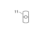
- FIG. 10 is an end view of the welding tip shown in FIG. 8 on the side from which the inserted welding wire protrudes, and is a bottom view of FIG. 9.
- the first layer submerged arc welding method according to the present invention is a method of first layer welding in submerged arc welding of high Cr-based CSEF steel, which can be either single or tandem. Also applies.
- a base material 10 is welded by arc welding using a welding tip 11 in which a welding wire 12 is inserted.
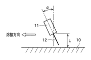
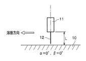
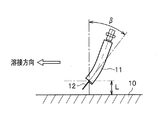
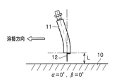
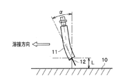
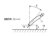
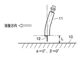
- the angle 11 is tilted forward (FIG. 1) or backward (FIG. 2) or perpendicular (FIG. 3) with respect to the welding direction.
- tandem submerged arc welding As shown in FIG. 4, welding is performed using two of the leading electrode (welding tip) 11a and the trailing electrode (welding tip) 11b in which the welding wires 12a and 12b are respectively inserted. To do. Further, the submerged arc welding uses a welding flux (not shown) for both single and tandem systems. Further, the chip / base material distance, the chip shape, and the chip angle will be described later.
- the first layer welding method according to the present invention is a submerged arc welding method applied to the first pass, that is, the first layer welding.
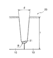
- the first layer weld metal 21 is solidified at the groove bottom in the groove.
- a new weld metal 22 is laminated upward (in the direction of the white arrow in the figure) as shown in FIG.
- the first layer welding method according to the present invention is intended for high Cr system CSEF steel as a base material (material to be welded).
- high Cr-based CSEF steel there are various standards for high Cr-based CSEF steel.
- SA387Gr There are T10, X10CrMoVNb9-1 defined in EN standards (European standards), Fire SFVAF28, Fire SFVAF29, Fire STBA28, Fire STPA28, and Fire SCMV28 defined in thermal power technical standards.
- the components of the base material are C: 0.07 to 0.14 mass%, Si: 0.50 mass% or less, Mn: 0.70 mass% or less, Ni: 0.50 mass% or less, Cr: 8. 00 to 11.50 mass%, Mo: 0.25 to 1.10 mass%, V: 0.15 to 0.35 mass%, Nb: 0.04 to 0.10 mass%, P: 0.025 mass% % Or less, S: 0.015% by mass or less, N: 0.03 to 0.10% by mass, the balance being composed of Fe and inevitable impurities is preferable, and Cu: 1.70% by mass or less B: 0.060% or less, W: 2.50% or less, Co: 3.0% by mass or less.
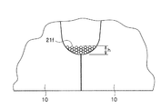
- the first layer welding method according to the present invention it is preferable to combine a base metal having the above components with a welding wire and a welding flux described later. Furthermore, in the first layer welding method according to the present invention, as shown in FIG. 7, a filler 21f having the following predetermined components is filled into the groove at a predetermined spraying height h and welded.
- filler In the first layer welding method according to the present invention, C: 0.10% by mass or less, Si: 0.50% by mass or less, Mn: 1.50% by mass or less, P: 0.025% by mass or less, S: 0.0. Filled with a metal powder or cut wire containing 025% by mass or less, the balance being Fe and inevitable impurities, as a filler, filling the groove of the base metal to a height of 1.0 to 4.0 mm and welding. .
- the filler will be described in more detail.
- C (C: 0.10 mass% or less) C causes a high temperature crack in the weld metal by lowering the melting point.
- the C content of the filler is 0.10% by mass or less, preferably 0.05% by mass or less, including the dilution of the base material.
- Si 0.50 mass% or less
- Si has the effect of adjusting the viscosity of the molten metal to adjust the bead shape.
- the Si content of the filler is 0.50 mass% or less, preferably 0.30 mass% or less.
- Mn 1.50 mass% or less
- Mn has the effect of adjusting the viscosity of the molten metal to adjust the bead shape.
- the Mn content of the filler is 1.50% by mass or less, preferably 1.30% by mass or less.
- each content of P and S in the filler is 0.025% by mass or less, and preferably less than 0.025% by mass.
- the filler may contain Cu, Cr, Mo, Ni, Nb, V, W, Co, N, etc. as unavoidable impurities, each 0.5 mass% or less, and 0.8 mass% or less in total. .
- the filler has a spraying height of 1.0 mm or more, preferably 1.5 mm or more.
- the filler has a spray height of 4.0 mm or less, preferably 3.5 mm or less.
- the metal powder of the above component or a cut wire may be applied.
- the metal powder preferably has an average particle size of 1 mm or less
- the cut wire preferably has a wire diameter and length (cut length) of 1 mm or less, respectively.
- the welded portion (the first layer weld metal 21 shown in FIG. 5) using the filler may be removed according to the required safety level of the joint performance after all the welding including the second and subsequent passes are completed.
- a known method such as gouging or machining can be applied.
- the welding wire used in the first layer welding method according to the present invention is C: 0.03 to 0.13 mass%, Si: 0.05 to 0.50 mass%, Mn: 0.50 to 2.20 mass%. Ni: more than 0.20% by mass and 1.00% by mass or less, Cr: 8.00 to 10.50% by mass, Mo: 0.20 to 1.20% by mass, V: 0.05 to 0.45 Mass%, Nb: 0.020 to 0.080 mass%, P: 0.015 mass% or less, S: 0.010 mass% or less, N: 0.02 to 0.08 mass%, the balance being Those composed of Fe and inevitable impurities are preferable, and further Cu: 1.70% by mass or less, B: 0.005% by mass or less, W: 2.0% by mass or less, Co: 3.0% by mass or less May be.
- the C content of the welding wire is preferably 0.03% by mass or more, and more preferably 0.04% by mass or more.
- the C content of the welding wire is preferably 0.13% by mass or less, and more preferably 0.12% by mass or less.
- the Si acts as a deoxidizer and has the effect of reducing the amount of oxygen in the deposited metal and improving the toughness of the weld metal.
- the Si content of the welding wire is preferably 0.05% by mass or more, more preferably more than 0.05% by mass.
- Si is a ferrite-forming element. If it is added in excess, specifically, if the Si content exceeds 0.50 mass%, ⁇ -ferrite remains in the weld metal and the toughness of the weld metal deteriorates. . Therefore, the Si content of the welding wire is preferably 0.50% by mass or less, more preferably 0.48% by mass or less, and further preferably 0.45% by mass or less.
- Mn acts as a deoxidizer and has the effect of reducing the amount of oxygen in the deposited metal and improving toughness.
- Mn is an austenite-forming element and has an effect of suppressing toughness deterioration due to residual ⁇ -ferrite in the weld metal.
- the Mn content of the welding wire is preferably 0.50% by mass or more, and more preferably 0.55% by mass or more.
- the Mn content of the welding wire is preferably 2.20% by mass or less, and more preferably 2.15% by mass or less.
- Ni is an austenite-forming element like Mn, and has the effect of suppressing toughness deterioration due to residual ⁇ -ferrite in the weld metal.
- the Ni content of the welding wire is preferably more than 0.20% by mass, more preferably 0.25% by mass or more, and further preferably 0.30% by mass or more.
- the NNi content of the welding wire is preferably 1.00% by mass or less, and more preferably 0.95% by mass or less.
- the total content of Mn and Ni in the welding wire is more preferably 1.50% by mass or less.
- Cr is a main element of high Cr-based CSEF steel, which is a material to be welded (base material) of the first layer welding method according to the present invention, and is an essential element for ensuring oxidation resistance and high temperature strength.
- the Cr content of the welding wire is preferably 8.00% by mass or more, and more preferably 8.05% by mass or more.
- Cr is a ferrite-forming element. When it is added excessively, specifically, when the Cr content exceeds 10.50 mass%, ⁇ -ferrite remains and the toughness of the weld metal deteriorates. Therefore, the Cr content of the welding wire is preferably 10.50% by mass or less, and more preferably 10.45% by mass or less.
- Mo is a solid solution strengthening element and has the effect of improving the creep rupture strength.
- the Mo content of the welding wire is preferably 0.20% by mass or more, and more preferably 0.22% by mass or more.
- Mo is a ferrite-forming element, when it is added in excess, specifically, if the Mo content exceeds 1.20% by mass, ⁇ -ferrite remains in the weld metal and the toughness of the weld metal. Deteriorates. Therefore, the Mo content in the welding wire is preferably 1.20% by mass or less, and more preferably 1.18% by mass or less.
- V is a precipitation strengthening element, and has the effect of improving the creep rupture strength by precipitating as carbonitride.
- the V content of the welding wire is preferably 0.05% by mass or more, and more preferably 0.10% by mass or more.
- V is also a ferrite-forming element, and when added in excess, specifically, if the V content exceeds 0.45 mass%, ⁇ -ferrite remains in the weld metal and the toughness of the weld metal deteriorates. To do. Therefore, the V content of the welding wire is preferably 0.45% by mass or less, and more preferably 0.40% by mass or less.
- Nb is an element that contributes to the stabilization of creep rupture strength by precipitation as a solid solution strengthening and nitride.
- the Nb content of the welding wire is preferably 0.020% by mass or more, and more preferably 0.022% by mass or more.
- Nb is also a ferrite-forming element. If it is contained in excess, specifically, if the Nb content exceeds 0.080% by mass, ⁇ -ferrite remains in the weld metal and the toughness of the weld metal deteriorates. To do. Therefore, the Nb content of the welding wire is preferably 0.080% by mass or less, and more preferably 0.078% by mass or less.
- P and S are elements that increase the hot cracking susceptibility.
- the P content of the welding wire is preferably regulated to 0.015% by mass or less, and more preferably 0.010% by mass or less.
- the N content of the welding wire is preferably 0.02% by mass or more, and more preferably 0.03% by mass or more.
- the N content of the welding wire is preferably 0.08% by mass or less, and more preferably 0.07% by mass or less.
- Cu is an austenite generating element and has an effect of suppressing toughness deterioration due to residual ⁇ -ferrite in the weld metal.
- the Cu content of the welding wire is preferably 1.70% by mass or less, more preferably 1.00% by mass or less, and further preferably 0.50% by mass or less. Cu may be contained on the surface of the welding wire by plating.
- the B content of the welding wire is preferably 0.005% by mass or less, more preferably 0.003% by mass or less, and further preferably 0.0015% by mass or less.
- W is an element that contributes to stabilization of creep rupture strength by solid solution strengthening of the matrix and precipitation of fine carbides.
- W is also a ferrite-forming element, if it is contained excessively, specifically, if the W content exceeds 2.0 mass%, ⁇ -ferrite remains in the weld metal, and the toughness of the weld metal is reduced. to degrade.
- the W content of the welding wire is preferably 2.0% by mass or less, more preferably 1.8% by mass or less, and even more preferably 1.7% by mass or less.
- Co is an element that suppresses residual ⁇ ferrite.
- the Co content of the welding wire is preferably 3.0% by mass or less, more preferably 2.0% by mass or less, and further preferably 1.8% by mass or less.
- the welding wire may contain 0.02% by mass or less of Ti, Al, etc. as inevitable impurities, and 0.04% by mass or less in total.
- the welding wire preferably has a wire diameter of 3 to 5 mm. If the wire diameter is less than 3 mm, a sufficient amount of welding cannot be obtained, and the welding efficiency may be impaired. On the other hand, if the wire diameter exceeds 5 mm, the amount of welding becomes excessive, and even with the first layer welding method according to the present invention, it may be difficult to suppress high temperature cracking of the first layer.
- the welding flux used in the first layer welding method according to the present invention preferably has a basicity represented by the following formula of 1.0 to 3.3.
- Basicity [CaF 2 + CaO + MgO + SrO + Na 2 O + Li 2 O + 1/2 (MnO + FeO)] / [SiO 2 +1/2 (Al 2 O 3 + TiO 2 + ZrO 2 )]
- each compound in the above formula represents the content (mass%) of the compound in the welding flux.
- the welding flux preferably has a basicity of 1.0 or more, and more preferably 1.3 or more.
- the welding flux preferably has a basicity of 3.3 or less, and more preferably 3.2 or less.
- the other components such as the respective contents of the compounds constituting the welding flux are specifically defined. It is not something.
- the tip / base material distance is a distance L between the base material 10 and a portion where the welding wire 12 finally protrudes from the welding tip 11 as shown in FIGS. 1 to 3 and FIGS. 11 to 16.
- a welding wire made of a base material and a co-material that is, a high Cr-based CSEF steel has a higher electric resistance than a low Cr-based CSEF steel, and therefore has a large Joule heat generation, and has the same size. Even with current, the amount of welding increases.
- the Joule heat generation increases as the distance between the tip and the base material increases. Specifically, when the tip / base metal distance exceeds 40 mm, the amount of welding becomes excessive.
- the distance between the tip and the base material is preferably managed in the range of 20 to 40 mm, more preferably in the range of 25 to 35 mm.
- the tip shape may be a straight tube shown in FIGS. 1 to 3, a bend square shape shown in FIGS. 8 to 10, or FIG.
- the shape as shown in 3b may be used, and is appropriately selected from the viewpoint of ensuring the welding wire feedability and feeding position stabilization.
- a bend square member that is bent in such a range that the tip end portion (the lower end in FIGS. 8 and 9) that protrudes the welding wire 12 (see FIGS. 11 to 16) does not hinder the wire feeding.
- the feeding position is stabilized, and as a result, the wire feeding speed is stabilized.
- the tip angle includes a line perpendicular to the surface of the base material 10 and an axis at a portion where the welding wire 12 finally protrudes from the welding tip 11.
- the tip angle affects the degree of heating of the wire by the welding arc, and as a result, increases or decreases the welding wire feed speed.
- the tip angle is the receding angle ⁇ (see FIGS. 1, 11, and 15) when the tip angle is ⁇ (see FIGS. 2, 12, and 15). 14)
- the wire feeding speed is increased.
- the feeding speed of the welding wire is preferably 50 g / min or more, and more preferably 55 g / min or more.
- the feeding speed of the welding wire is preferably 120 g / min or less, and more preferably 115 g / min or less.
- the welding speed is preferably 20 cm / min or more, and more preferably 25 cm / min or more.
- the welding speed is preferably 60 cm / min or less, and more preferably 55 cm / min or less.
- the amount of deposition per unit weld length is the welding wire feed speed / welding speed. If the welding amount per unit weld length is less than 1.8 g / cm, the welding amount is insufficient, the bead shape becomes unstable, and poor fusion or slag entrainment occurs. Therefore, the deposition amount per unit weld length is preferably 1.8 g / cm or more, and more preferably 2.0 g / cm or more.
- the deposition amount per unit weld length is preferably 4.5 g / cm or less, and more preferably 4.3 g / cm or less.
- the welding current and arc voltage are adjusted as a means for controlling the welding wire feeding speed within an appropriate range.
- the power supply characteristic may be either a drooping characteristic or a constant voltage characteristic.
- the drooping characteristic is a characteristic of a power source that can perform stable welding with little change in current even if the arc length varies. Specifically, when the arc length becomes long, the wire feed speed is temporarily increased, and when the arc length becomes short, the wire feed speed is slowed to stabilize the current. Turn into. Either DCEP (Direct Current Electrode Positive) or AC (Alternating Current) may be applied as the power polarity.
- the first layer welding method according to the present invention is applicable also to tandem welding, and it is preferable to apply the following conditions.
- the tip shape is a straight tube shown in FIG. 4, a bend square shape shown in FIGS. 8 to 10, or FIG.
- the shape is appropriately selected from the shapes shown in 3b.
- the tip / base material distance is the distance between the base material 10 and the portion where the welding wire 12 a (12 b) finally protrudes from the welding tip 11 a (11 b), as in the case of single welding.
- L is preferably in the range of 20 to 40 mm.
- the tip / base material distance may not be the same between the leading electrode 11a and the trailing electrode 11b.
- the tip / base material distance when the tip shape of the welding tips 11a and 11b is the bend square shape shown in FIGS. 8 to 10 is indicated by the distance L between the welding tip 11 and the base material 10 in FIGS. Street.
- the distance between the leading electrode 11a and the trailing electrode 11b is preferably 15 to 25 mm. A good bead shape can be obtained if it is within the range of 15 mm to 25 mm.
- the tip angle is a line perpendicular to the surface of the base material 10 and a portion where the welding wire 12a (12b) finally protrudes from the welding tip 11a (11b) as in the case of single welding.
- the tip angle (receding angle ⁇ , advancing angle ⁇ ) is managed within a range of ⁇ 60 ° (from the receding angle 60 ° to the advancing angle 60 °). Preferred for stabilization.
- the tip angles ⁇ and ⁇ when the tip shape of the welding tips 11a and 11b is the bend square shape shown in FIGS. 8 to 10 are as shown by the tip angles ⁇ and ⁇ of the welding tip 11 in FIGS.
- the feeding speed of the welding wire is in the range of 45 to 90 g / min at the leading electrode and 60 to 110 g / min at the trailing electrode.
- the welding speed is preferably in the range of 30 to 55 cm / min.
- the amount of welding per unit weld length is (feeding speed of the welding wire of the leading electrode + feeding speed of the welding wire of the trailing electrode) / welding speed.
- the welding amount per unit weld length is less than 2.8 g / cm, the welding amount is insufficient and the welding efficiency is lowered.
- the amount of welding per unit weld length exceeds 3.8 g / cm, the amount of welding becomes excessive, and the amount of solidification shrinkage of the molten metal becomes excessive and the shape of the penetration is not formed. However, it becomes perpendicular to the final solidified part and hot cracks are likely to occur. Therefore, the amount of deposition per unit weld length is preferably in the range of 2.8 to 3.8 g / cm.
- Power supply characteristics may be either drooping characteristics or constant voltage characteristics as in single welding. Further, either DCEP or AC may be applied as the polarity. Moreover, you may apply V connection and Scott connection.
- the first layer welding method according to the present invention may be applied to a base material having a plate thickness of less than 150 mm. Further, application to the X groove is not excluded. When applied to the X groove, in the welding to the back side, the first layer welding is performed by filling the groove with the filler in the same manner as the front side. Further, after the first pass after the first layer welding by the first layer welding method according to the present invention, it can be welded by submerged arc welding in the same manner as the welding conditions except for the filler or under different conditions, Alternatively, a welding method such as gas shield arc welding may be applied.
- a plate material having a thickness of 250 mm made of high Cr-based CSEF steel having the components shown in Table 1 is prepared.
- the radius of curvature R of the groove groove bottom is 10 mm, and the groove angle ⁇ is 4 °.
- a narrow groove was formed as a base material (see FIG. 5).
- the shape (metal powder, cut wire) and the filler of a component shown in Table 4 were prepared, and it filled with the spraying height h (refer FIG. 7) shown in Table 4 in the groove
- the filler the metal powder has an average particle diameter of 75 ⁇ m
- the cut wire has a wire diameter of 1 mm, and a cut length of 1 mm.
- the test body 20 shown in FIG. 5 was produced by performing one pass for each layer under the following conditions.
- the bead shape was visually observed. Specifically, in the evaluation of slag peelability, the surface appearance of the trace of the slag was peeled off, and when the bead shape was stable, “ ⁇ ” was passed, and when unstable, “ ⁇ ” was rejected. 4 shows.
- the specimen No. In Nos. 1 to 3 the filler component and the spread height of the groove were within the range of the present invention, and the soundness of the welded portion and the hot crack resistance were good.
- specimen No. In No. 4 since the C content of the filler was excessive, hot cracking occurred due to the concentration of C in the weld metal.
- Test material No. No. 5 shows that the Si content of the filler is the test material No. In No. 6, slag seizure occurred because the Mn content of the filler was excessive.
- Test material No. No. 7 has a P content of the filler of test material No. In No. 8, since the S content of the filler was excessive, hot cracking occurred.
Landscapes
- Engineering & Computer Science (AREA)
- Mechanical Engineering (AREA)
- Physics & Mathematics (AREA)
- Plasma & Fusion (AREA)
- Chemical & Material Sciences (AREA)
- Materials Engineering (AREA)
- Arc Welding In General (AREA)
- Nonmetallic Welding Materials (AREA)
Abstract
高Cr系CSEF鋼のサブマージアーク溶接において、工程・労力の増大によらずに初層高温割れの発生を抑制できる溶接方法を提供する。 C:0.10質量%以下、Si:0.50質量%以下、Mn:1.50質量 %以下、P:0.025質量%以下、S:0.025質量%以下を含有し、残部がFeおよび不可避的不純物からなる金属粉末またはカットワイヤ21fを、母材10の開先内へ散布高さh:1.0~4.0mmに充填して初層溶接することを特徴とする。初層溶接において、前記金属粉末等21fにより溶接金属の融点降下が抑制されて、高温割れを防止することができる。
Description
本発明は、高Cr系CSEF(Creep Strength-Enhanced Ferritic steel:クリープ強度強化フェライト)鋼のサブマージアーク溶接方法に関し、特に、初層溶接方法に関する。
火力発電ボイラ、タービン、脱硫や改質(重油分解)用の化学反応容器(リアクタ)は、いずれも高温、高圧で運転されるため、材料として、1.25Cr-0.5Mo鋼、2.25Cr-1.0Mo鋼、2.25Cr-1.0Mo-V鋼等が適用されている。近年、重油の有効利用や石油精製においてさらなる高能率化が求められており、8質量%以上のCrを含有する高Cr系CSEF鋼の適用が検討されている。高Cr系CSEF鋼には、ASTM(American Society for Testing and Materials:米国材料試験協会)規格やASME(American Society of Mechanical Engineers:米国機械協会)規格に規定されるSA387Gr.91、SA213Gr.T91等がある。
火力発電ボイラ、タービン、リアクタは、鍛造リング、パイプ、または曲げ加工鋼板を適宜組み合わせて溶接して組み立てられる。ここで、例えば鍛造リングは、板厚150~450mm、最大外径7m弱、全長数~数10mにもなる。溶接方法としては、被覆アーク溶接、TIG(Tungsten Inert Gas)溶接、サブマージアーク溶接が用いられ、特に、サブマージアーク溶接は他の溶接方法と比較して高能率であることから多用されている。ところが、高Cr系CSEF鋼にサブマージアーク溶接を行うと、初層溶接で高温割れを生じ易い。
サブマージアーク溶接の初層溶接の高温割れ防止の技術として、例えば特許文献1には、高炭素鋼であるC含有量0.27質量%のJIS SF50やASTM A148の狭開先サブマージアーク溶接において、母材間の継ぎ目に、具体的にはV開先やX開先の初層位置に、スペーサとしてC含有量0.10質量%以下の低炭素鋼や溶接金属からなる異物・異材を介在させる技術が開示されている。この特許文献1には、高炭素鋼材の狭開先溶接においてその初層溶接ビードで高温割れが発生し易いのは、母材希釈による母材のCの溶接金属へのピックアップであると記載されている。すなわち、溶接金属のC濃度が高くなって融点が低下することにより、高温割れが発生し易くなる。そのため、特許文献1では、初層溶接において、低炭素の鋼材や溶接金属からなる異物・異材のスペーサ上に溶接することにより、母材からのCピックアップの影響を緩和して、高温割れを防止することが開示されている。
ここで、高Cr系CSEF鋼は、C含有量については、例えばASTM A182 F91で0.08~0.12質量%、すなわち最大でも0.12質量%であり、従来の1.25Cr-0.5Mo鋼、2.25Cr-1.0Mo鋼、2.25Cr-1.0Mo-V鋼と同程度である。しかし、高Cr系CSEF鋼と共材で構成される溶接ワイヤは、1.25Cr-0.5Mo鋼、2.25Cr-1.0Mo鋼、2.25Cr-1.0Mo-V鋼よりも電気抵抗が高く、そのためジュール発熱が高く、溶接電流の大きさが同じであればより溶融し易い。したがって、高Cr系CSEF鋼の溶接においては、溶着金属の量(溶着量)が多くなり、さらに溶着金属の凝固収縮量が1.25Cr-0.5Mo鋼、2.25Cr-1.0Mo鋼、2.25Cr-1.0Mo-V鋼よりも大きいため、高温割れの抑制がいっそう困難である。
また、厚板を高能率で溶接するためには、溶接入熱を上げる、すなわち溶接電流を大きく、アーク電圧を高くして、溶接速度を低めにすることが有効である。しかし、溶接入熱を上げると、特に狭開先ではビード形状がなし型となり易く、高温割れの発生リスクが高くなる。ここで問題となる高温割れは、溶着金属中に含まれるP,S,Si,Nb等の低融点化合物が凝固時にデンドライト間やオーステナイト結晶粒界に偏析し、溶接収縮ひずみが加わって発生する割れである。そのため、高温割れの抑制策の一つとして、ワイヤの成分、具体的には、P,S等の不純物を超高純度(EHP:Extra High Purity)溶解で100ppm以下に抑えることは効果的である。しかしながら、超高純度溶解は、電子ビーム溶解や専用の特殊炉壁耐火材を使わざるを得ないことから経済的に難点がある。このため、一般的な不純物レベルでも、高温割れの発生を抑制できる技術が求められている。
さらに、特許文献1に記載されたスペーサを適用するには、バタリング、あるいはスペーサの据付け、固定、精度管理等の多大な工程・労力が発生することになる。また、成分が母材と大きく異なる異物・異材をスペーサとするために、溶接部も含め、要求される継手性能の保安水準を満足しない虞がある。特許文献1においては、溶接後に裏当金をガウジングで除去すると記載されているが、溶接されたスペーサはもちろんその溶接金属を除去することは記載されていない。すなわち特許文献1は、異物・異材となるスペーサの継手内部への残留を許容する用途を対象にしていると考えられる。したがって、異物・異材をスペーサとする特許文献1の溶接方法は、生産性・経済性・継手性能の保安水準という視点から、火力発電ボイラ等には適用困難である。
本発明は、前記問題点に鑑みてなされたものであり、その課題は、高Cr系CSEF鋼のサブマージアーク溶接において、工程・労力の増大によらずに初層高温割れの発生を抑制できる初層サブマージアーク溶接方法を提供することにある。
本発明者らは、鋭意研究した結果、開先に所定の成分の充填剤を充填することにより、初層の溶接金属の融点降下を抑制することに想到した。
すなわち、本発明に係る初層サブマージアーク溶接方法は、高Cr系CSEF鋼を母材とし、C:0.10質量%以下、Si:0.50質量%以下、Mn:1.50質量%以下、P:0.025質量%以下、S:0.025質量%以下を含有し、残部がFeおよび不可避的不純物からなる金属粉末またはカットワイヤを、前記母材の開先内へ散布高さ1.0~4.0mmに充填して溶接することを特徴とする。
かかる方法によれば、C含有量を所定値以下に制御した充填剤で母材希釈が抑えられ、溶接金属の融点が低下することなく、初層高温割れが防止される。
本発明に係る初層サブマージアーク溶接方法では、溶接ワイヤは、C:0.03~0.13質量%、Si:0.05~0.50質量%、Mn:0.50~2.20質量%、P:0.015質量%以下、S:0.010質量%以下、Ni:0.20質量%を超え1.00質量%以下、Cr:8.00~10.50質量%、Mo:0.20~1.20質量%、V:0.05~0.45質量%、Nb:0.020~0.080質量%、N:0.02~0.08質量%を含有し残部がFeおよび不可避的不純物であることが好ましい。
かかる方法によれば、初層高温割れをより確実が防止できる。
本発明に係る初層サブマージアーク溶接方法では、溶接ワイヤは、Cu:1.70質量%以下、B:0.005質量%以下、W:2.0質量%以下およびCo:3.0質量%以下からなる群から選択される少なくとも1つ以上をさらに含有することが好ましい。
かかる方法によれば、溶接金属におけるδ-フェライトの残留による靱性劣化を抑制する、またはクリープ破断強度を高めることができる。
本発明に係る初層サブマージアーク溶接方法では、溶接に用いる溶接フラックスは、以下の式で示される塩基度が1.0~3.3であることが好ましい。
塩基度=(CaF2+CaO+MgO+SrO+Na2O+Li2O+1/2(MnO+FeO))/(SiO2+1/2(Al2O3+TiO2+ZrO2))
ここで、各化合物はフラックス全質量あたりの各化合物の含有量(質量%)を示す。
塩基度=(CaF2+CaO+MgO+SrO+Na2O+Li2O+1/2(MnO+FeO))/(SiO2+1/2(Al2O3+TiO2+ZrO2))
ここで、各化合物はフラックス全質量あたりの各化合物の含有量(質量%)を示す。
かかる方法によれば、溶接金属の酸素量を抑制し、かつビードの外観および形状の不良発生を抑制できる。
本発明に係る初層サブマージアーク溶接方法では、初層サブマージアーク溶接方法が初層シングルサブマージアーク溶接方法であり、ワイヤ送給速度(V)を50~120g/min、溶接速度(v)を20~60cm/minとし、前記ワイヤ送給速度と前記溶接速度との比で求める単位溶接長さ当りの溶着量(V/v)を1.8~4.5g/cmとする条件で溶接することが好ましい。
かかる方法によれば、融合不良およびスラグ巻込みをより確実に抑制でき、また高温割れの発生をより確実に抑制できる。
本発明に係る初層サブマージアーク溶接方法では、初層サブマージアーク溶接方法が初層タンデムサブマージアーク溶接方法であり、先行極のワイヤ送給速度VLを45~90g/min、後行極のワイヤ送給速度VTを60~110g/min、溶接速度vを30~55cm/min、単位長さ当りの溶着量を2.8~3.8g/cmとする条件で溶接することが好ましい。
かかる方法によれば、溶接効率の低下を抑制でき、また高温割れの発生をより確実に抑制できる。
本発明に係る初層サブマージアーク溶接方法では、チップ/母材間距離が20~40mmであることが好ましい。
かかる方法によれば、溶着量が過剰となるのを抑制でき、またチップ先端がアークによって溶損するのを抑制できる。
本発明に係る初層サブマージアーク溶接方法では、チップ角度は、後退角αが0°から60°までの範囲、前進角βが0°から60°までの範囲であることが好ましい。
かかる方法によれば、ワイヤ供給速度を容易に安定化させることができる。
本発明に係る初層サブマージアーク溶接方法では、チップ形状は、直管状またはベンド角材状であることが好ましい。
かかる方法によれば、ワイヤ供給速度を容易に安定化させることができる。
本発明に係る初層サブマージアーク溶接方法では、初層サブマージアーク溶接方法が初層タンデムサブマージアーク溶接方法であり、先行極と後行極との間の極間距離が15mm~25mmである
かかる方法によれば、良好なビード形状を獲得できる。
本発明に係る初層サブマージアーク溶接方法によれば、高Cr系CSEF鋼の溶接において、工程・労力の増大によらずに初層高温割れの発生を抑制することができる。
以下、本発明の実施の形態について詳細に説明する。
本発明に係る初層サブマージアーク溶接方法(以下、本発明に係る初層溶接方法)は、高Cr系CSEF鋼のサブマージアーク溶接における初層溶接の方法であり、シングル、タンデムのいずれの方式にも適用される。シングルサブマージアーク溶接は、例えば図1~3に示すように、母材10を、溶接ワイヤ12が内挿された溶接チップ11を用いて、アーク溶接で溶接するものであり、1台の溶接チップ11の角度(チップ角度)を溶接方向に対して前傾(図1)または後傾(図2)させ、あるいは垂直(図3)にする。一方、タンデムサブマージアーク溶接は、図4に示すように、溶接ワイヤ12a,12bがそれぞれ内挿された先行極(溶接チップ)11aおよび後行極(溶接チップ)11bの2台を同時に用いて溶接するものである。さらにサブマージアーク溶接は、シングル、タンデムの各方式共に、図示しない溶接フラックスを用いる。また、チップ/母材間距離、チップ形状、チップ角度については、後記にて説明する。
本発明に係る初層サブマージアーク溶接方法(以下、本発明に係る初層溶接方法)は、高Cr系CSEF鋼のサブマージアーク溶接における初層溶接の方法であり、シングル、タンデムのいずれの方式にも適用される。シングルサブマージアーク溶接は、例えば図1~3に示すように、母材10を、溶接ワイヤ12が内挿された溶接チップ11を用いて、アーク溶接で溶接するものであり、1台の溶接チップ11の角度(チップ角度)を溶接方向に対して前傾(図1)または後傾(図2)させ、あるいは垂直(図3)にする。一方、タンデムサブマージアーク溶接は、図4に示すように、溶接ワイヤ12a,12bがそれぞれ内挿された先行極(溶接チップ)11aおよび後行極(溶接チップ)11bの2台を同時に用いて溶接するものである。さらにサブマージアーク溶接は、シングル、タンデムの各方式共に、図示しない溶接フラックスを用いる。また、チップ/母材間距離、チップ形状、チップ角度については、後記にて説明する。
本発明に係る初層溶接方法は、1パス目、すなわち初層溶接に適用されるサブマージアーク溶接方法である。初層溶接により、図5に示すように、開先内の溝底に初層溶接金属21が凝固する。その後、パスを繰り返すことにより、図6に示すように新たな溶接金属22が上へと(図中の白抜き矢印方向に)積層される。
(母材)
本発明に係る初層溶接方法は、母材(被溶接材)として高Cr系CSEF鋼を対象とするものである。高Cr系CSEF鋼には各種の規格があり、例えば、ASTM規格やASME規格に規定されたSA387Gr.T91、EN規格(European standards:欧州規格)に規定されたX10CrMoVNb9-1、火力技術基準に規定された火SFVAF28、火SFVAF29、火STBA28、火STPA28、火SCMV28がある。
本発明に係る初層溶接方法は、母材(被溶接材)として高Cr系CSEF鋼を対象とするものである。高Cr系CSEF鋼には各種の規格があり、例えば、ASTM規格やASME規格に規定されたSA387Gr.T91、EN規格(European standards:欧州規格)に規定されたX10CrMoVNb9-1、火力技術基準に規定された火SFVAF28、火SFVAF29、火STBA28、火STPA28、火SCMV28がある。
母材の成分としては、C:0.07~0.14質量%、Si:0.50質量%以下、Mn:0.70質量%以下、Ni:0.50質量%以下、Cr:8.00~11.50質量%、Mo:0.25~1.10質量%、V:0.15~0.35質量%、Nb:0.04~0.10質量%、P:0.025質量%以下、S:0.015質量%以下、N:0.03~0.10質量%を含有し、残部がFeおよび不可避的不純物からなるものが好ましく、さらに、Cu:1.70質量%以下、B:0.060%以下、W:2.50%以下、Co:3.0質量%以下を含有してもよい。
本発明に係る初層溶接方法においては、前記成分の母材に、後記の溶接ワイヤおよび溶接フラックスを組み合わせることが好ましい。さらに本発明に係る初層溶接方法においては、図7に示すように、以下の所定成分の充填剤21fを開先内へ所定の散布高さhに充填して溶接する。
(充填剤)
本発明に係る初層溶接方法は、C:0.10質量%以下、Si:0.50質量%以下、Mn:1.50質量%以下、P:0.025質量%以下、S:0.025質量%以下を含有し、残部がFeおよび不可避的不純物からなる金属粉末またはカットワイヤを充填剤として、母材の開先内へ散布高さ1.0~4.0mmに充填して溶接する。以下、充填剤について、さらに詳細に説明する。
本発明に係る初層溶接方法は、C:0.10質量%以下、Si:0.50質量%以下、Mn:1.50質量%以下、P:0.025質量%以下、S:0.025質量%以下を含有し、残部がFeおよび不可避的不純物からなる金属粉末またはカットワイヤを充填剤として、母材の開先内へ散布高さ1.0~4.0mmに充填して溶接する。以下、充填剤について、さらに詳細に説明する。
(C:0.10質量%以下)
Cは、溶着金属において、融点を低下させて高温割れを引き起こす。溶着金属の融点降下を防止するために、充填剤のC含有量は母材希釈も加味して0.10質量%以下とし、好ましくは0.05質量%以下である。
Cは、溶着金属において、融点を低下させて高温割れを引き起こす。溶着金属の融点降下を防止するために、充填剤のC含有量は母材希釈も加味して0.10質量%以下とし、好ましくは0.05質量%以下である。
(Si:0.50質量%以下)
Siは、溶融金属の粘性を調整してビード形状を整える作用を有する。一方で、0.50質量%を超えると、スラグ焼付きが発生してスラグ除去が困難となる。したがって、充填剤のSi含有量は0.50質量%以下とし、好ましくは0.30質量%以下である。
Siは、溶融金属の粘性を調整してビード形状を整える作用を有する。一方で、0.50質量%を超えると、スラグ焼付きが発生してスラグ除去が困難となる。したがって、充填剤のSi含有量は0.50質量%以下とし、好ましくは0.30質量%以下である。
(Mn:1.50質量%以下)
Mnは、溶融金属の粘性を調整してビード形状を整える作用を有する。一方で、1.50質量%を超えると、スラグ焼付きが発生してスラグ除去が困難となる。したがって、充填剤のMn含有量は1.50質量%以下とし、好ましくは1.30質量%以下である。
Mnは、溶融金属の粘性を調整してビード形状を整える作用を有する。一方で、1.50質量%を超えると、スラグ焼付きが発生してスラグ除去が困難となる。したがって、充填剤のMn含有量は1.50質量%以下とし、好ましくは1.30質量%以下である。
(P:0.025質量%以下、S:0.025質量%以下)
P,Sはそれぞれ、溶着金属において、融点を低下させて高温割れを引き起こす。したがって、充填剤のP,Sの各含有量は0.025質量%以下とし、好ましくは0.025質量%未満である。
P,Sはそれぞれ、溶着金属において、融点を低下させて高温割れを引き起こす。したがって、充填剤のP,Sの各含有量は0.025質量%以下とし、好ましくは0.025質量%未満である。
充填剤は、不可避的不純物として、Cu,Cr,Mo,Ni,Nb,V,W,Co,N等を各0.5質量%以下、合計で0.8質量%以下含有していてもよい。
(散布高さ:1.0~4.0mm)
充填剤は、散布高さが1.0mm未満では、充填剤の量が不足し、初層の溶着金属のCの濃化を抑制することができず、結果、溶着金属のC濃度が過剰となって、高温割れが抑制できない。したがって、充填剤は、散布高さを1.0mm以上とし、好ましくは1.5mm以上である。一方、充填剤を散布高さ4.0mmを超えて充填すると、充填剤の量が過剰になって、溶接ビード形状が凸ビードとなり、融合不良やスラグ巻込みを引き起こす。したがって、充填剤は、散布高さを4.0mm以下とし、好ましくは3.5mm以下である。
充填剤は、散布高さが1.0mm未満では、充填剤の量が不足し、初層の溶着金属のCの濃化を抑制することができず、結果、溶着金属のC濃度が過剰となって、高温割れが抑制できない。したがって、充填剤は、散布高さを1.0mm以上とし、好ましくは1.5mm以上である。一方、充填剤を散布高さ4.0mmを超えて充填すると、充填剤の量が過剰になって、溶接ビード形状が凸ビードとなり、融合不良やスラグ巻込みを引き起こす。したがって、充填剤は、散布高さを4.0mm以下とし、好ましくは3.5mm以下である。
充填剤は、前記成分の金属粉末、カットワイヤのいずれを適用してもよい。金属粉末は、平均粒径が1mm以下であることが好ましく、カットワイヤは、ワイヤ径および長さ(カット長)がそれぞれ1mm以下であることが好ましい。
なお、充填剤による溶接部(図5に示す初層溶接金属21)は、2パス目以降も含むすべての溶接が完了した後に、要求される継手性能の保安水準に応じて除去されてもよい。除去方法は、ガウジングや機械加工等、公知の方法を適用することができる。
(溶接ワイヤ)
本発明に係る初層溶接方法に使用する溶接ワイヤは、C:0.03~0.13質量%、Si:0.05~0.50質量%、Mn:0.50~2.20質量%、Ni:0.20質量%を超え1.00質量%以下、Cr:8.00~10.50質量%、Mo:0.20~1.20質量%、V:0.05~0.45質量%、Nb:0.020~0.080質量%、P:0.015質量%以下、S:0.010質量%以下、N:0.02~0.08質量%を含有し、残部がFeおよび不可避的不純物からなるものが好ましく、さらに、Cu:1.70質量%以下、B:0.005質量%以下、W:2.0質量%以下、Co:3.0質量%以下を含有してもよい。
本発明に係る初層溶接方法に使用する溶接ワイヤは、C:0.03~0.13質量%、Si:0.05~0.50質量%、Mn:0.50~2.20質量%、Ni:0.20質量%を超え1.00質量%以下、Cr:8.00~10.50質量%、Mo:0.20~1.20質量%、V:0.05~0.45質量%、Nb:0.020~0.080質量%、P:0.015質量%以下、S:0.010質量%以下、N:0.02~0.08質量%を含有し、残部がFeおよび不可避的不純物からなるものが好ましく、さらに、Cu:1.70質量%以下、B:0.005質量%以下、W:2.0質量%以下、Co:3.0質量%以下を含有してもよい。
Cは、Nと共に、Cr,Mo,W,V,Nb,Bと結合して各種炭窒化物を析出し、クリープ破断強度を向上させる効果がある。この効果を十分に得るために、溶接ワイヤのC含有量は0.03質量%以上が好ましく、0.04質量%以上がより好ましい。一方、Cを過剰に添加すると、具体的にはC含有量が0.13質量%を超えると、耐高温割れ性が劣化する。したがって、溶接ワイヤのC含有量は0.13質量%以下が好ましく、0.12質量%以下がより好ましい。
Siは、脱酸剤として作用し、溶着金属中の酸素量を低減して溶接金属の靱性を改善する効果がある。この効果を十分に得るために、溶接ワイヤのSi含有量は0.05質量%以上が好ましく、0.05質量%超がより好ましい。一方、Siはフェライト生成元素であり、過剰に添加すると、具体的にはSi含有量が0.50質量%を超えると、溶接金属におけるδ-フェライトの残留を引き起こし、溶接金属の靱性が劣化する。したがって、溶接ワイヤのSi含有量は0.50質量%以下が好ましく、0.48質量%以下がより好ましく、0.45質量%以下がさらに好ましい。
Mnは、脱酸剤として作用し、溶着金属中の酸素量を低減して靱性を改善する効果がある。また、Mnは、オーステナイト生成元素であり、溶接金属におけるδ-フェライトの残留による靱性劣化を抑制する効果がある。これらの効果を十分に得るために、溶接ワイヤのMn含有量は0.50質量%以上が好ましく、0.55質量%以上がより好ましい。一方、Mn含有量が2.20質量%を超えても、溶接金属の靱性が劣化する。したがって、溶接ワイヤのMn含有量は2.20質量%以下が好ましく、2.15質量%以下がより好ましい。
Niは、Mnと同様にオーステナイト生成元素であり、溶接金属におけるδ-フェライトの残留による靱性劣化を抑制する効果がある。この効果を十分に得るために、溶接ワイヤのNi含有量は0.20質量%超が好ましく、0.25質量%以上がより好ましく、0.30質量%以上がさらに好ましい。一方、Ni含有量が1.00質量%を超えても、溶接金属の靱性が劣化する。したがって、溶接ワイヤのNNi含有量は1.00質量%以下が好ましく、0.95質量%以下がより好ましい。
さらに、MnおよびNiの合計含有量が1.50質量%を超えると、溶接金属の靱性が劣化すると共に、溶着金属のAc1変態点が低下して高温焼戻しが不可能となり組織の安定化処理ができなくなる。したがって、溶接ワイヤのMnおよびNiの合計含有量は、1.50質量%以下がさらに好ましい。
Crは、本発明に係る初層溶接方法の被溶接材(母材)である高Cr系CSEF鋼の主要元素であり、耐酸化性および高温強度を確保するために不可欠な元素である。この効果を十分に得るために、溶接ワイヤのCr含有量は8.00質量%以上が好ましく、8.05質量%以上がより好ましい。一方、Crはフェライト生成元素であり、過剰に添加すると、具体的にはCr含有量が10.50質量%を超えると、δ-フェライトの残留を引き起こし、溶接金属の靱性が劣化する。したがって、溶接ワイヤのCr含有量は10.50質量%以下が好ましく、10.45質量%以下がより好ましい。
Moは、固溶強化元素であり、クリープ破断強度を向上させる効果がある。この効果を十分に得るために、溶接ワイヤのMo含有量は0.20質量%以上が好ましく、0.22質量%以上がより好ましい。一方、Moはフェライト生成元素であるため、過剰に添加すると、具体的には、Moを含有量が1.20質量%を超えると、溶接金属におけるδ-フェライトの残留を引き起こし、溶接金属の靱性が劣化する。したがって、溶接ワイヤのMo含有量は1.20質量%以下が好ましく、1.18質量%以下がより好ましい。
Vは、析出強化元素であり、炭窒化物として析出してクリープ破断強度を向上させる効果がある。この効果を十分に得るために、溶接ワイヤのV含有量は0.05質量%以上が好ましく、0.10質量%以上がより好ましい。一方、Vはフェライト生成元素でもあり、過剰に添加すると、具体的には、V含有量が0.45質量%を超えると、溶接金属におけるδ-フェライトの残留を引き起こし、溶接金属の靱性が劣化する。したがって、溶接ワイヤのV含有量は0.45質量%以下が好ましく、0.40質量%以下がより好ましい。
Nbは、固溶強化および窒化物として析出してクリープ破断強度の安定化に寄与する元素である。この効果を十分に得るために、溶接ワイヤのNb含有量は0.020質量%以上が好ましく、0.022質量%以上がより好ましい。一方、Nbはフェライト生成元素でもあり、過剰に含有すると、具体的には、Nb含有量が0.080質量%を超えると、溶接金属におけるδ-フェライトの残留を引き起こし、溶接金属の靱性が劣化する。したがって、溶接ワイヤのNb含有量は0.080質量%以下が好ましく、0.078質量%以下がより好ましい。
PおよびSは、それぞれ高温割れ感受性を高める元素である。P含有量が0.015質量%を超える場合、または、S含有量が0.010質量%を超える場合、耐高温割れ性が劣化する。したがって、溶接ワイヤのP含有量は0.015質量%以下に規制することが好ましく、0.010質量%以下がより好ましい。また、溶接ワイヤのS含有量は0.010質量%以下に規制することが好ましく、0.009質量%以下がより好ましい。
Nは、Cと共に、Cr,Mo,W,V,Nb,Bと結合して各種炭窒化物を析出し、クリープ破断強度を向上させる効果がある。この効果を十分に得るために、溶接ワイヤのN含有量は0.02質量%以上が好ましく、0.03質量%以上がより好ましい。一方、Nを過剰に含有すると、具体的には、N含有量が0.08質量%を超えると、スラグ剥離性が劣化する。したがって、溶接ワイヤのN含有量は0.08質量%以下が好ましく、0.07質量%以下がより好ましい。
Cuは、オーステナイト生成元素であり、溶接金属におけるδ-フェライトの残留による靱性劣化を抑制する効果がある。一方、過剰に含有すると、具体的には、Cu含有量が1.70質量%を超えると、高温割れを引き起こす。したがって、溶接ワイヤのCu含有量は1.70質量%以下が好ましく、1.00質量%以下がより好ましく、0.50質量%以下がさらに好ましい。Cuの含有方法は、溶接ワイヤ表面へのメッキでも構わない。
Bは、微量含有により炭化物を分散・安定化させ、クリープ破断強度を高める効果がある。一方、過剰に含有すると、具体的には、B含有量が0.005質量%を超えると、高温割れを引き起こす。したがって、溶接ワイヤのB含有量は0.005質量%以下が好ましく、0.003質量%以下がより好ましく、0.0015質量%以下がさらに好ましい。
Wは、マトリックスの固溶強化と微細炭化物析出によってクリープ破断強度の安定化に寄与する元素である。一方、Wはフェライト生成元素でもあるため、過剰に含有すると、具体的には、W含有量が2.0質量%を超えると、溶接金属におけるδ-フェライトの残留を引き起こし、溶接金属の靱性が劣化する。したがって、溶接ワイヤのW含有量は2.0質量%以下が好ましく、1.8質量%以下がより好ましく、1.7質量%以下がさらに好ましい。
Coは、δフェライトの残留を抑制する元素である。一方、Coは過剰に含有すると、具体的には、Co含有量が3.0質量%を超えると、Ac1点を下げるため、高温焼戻しが不可能となり組織の安定化処理ができなくなる。したがって、溶接ワイヤのCo含有量は3.0質量%以下が好ましく、2.0質量%以下がより好ましく、1.8質量%以下がさらに好ましい。
溶接ワイヤは、不可避的不純物として、Ti,Al等を各0.02質量%以下、合計で0.04質量%以下含有していてもよい。
溶接ワイヤは、ワイヤ径が3~5mmであることが好ましい。ワイヤ径が3mm未満では、十分な溶着量を得ることができず、溶接能率が損なわれる場合がある。一方、ワイヤ径が5mmを超えると、溶着量が過剰になり、本発明に係る初層溶接方法であっても、初層の高温割れを抑制することが困難となる場合があるからである。
(溶接フラックス)
本発明に係る初層溶接方法に使用する溶接フラックスは、次式で表される塩基度が1.0~3.3であることが好ましい。塩基度=[CaF2+CaO+MgO+SrO+Na2O+Li2O+1/2(MnO+FeO)]/[SiO2+1/2(Al2O3+TiO2+ZrO2)]
ここで、上式における各化合物は、当該化合物の溶接フラックスにおける含有量(質量%)を表す。
本発明に係る初層溶接方法に使用する溶接フラックスは、次式で表される塩基度が1.0~3.3であることが好ましい。塩基度=[CaF2+CaO+MgO+SrO+Na2O+Li2O+1/2(MnO+FeO)]/[SiO2+1/2(Al2O3+TiO2+ZrO2)]
ここで、上式における各化合物は、当該化合物の溶接フラックスにおける含有量(質量%)を表す。
溶接フラックスの塩基度が1.0未満では、溶接金属中の酸素量が十分に低減せず、溶接金属の靭性が低下する。したがって、溶接フラックスは、塩基度が1.0以上であることが好ましく、1.3以上がより好ましい。一方、溶接フラックスの塩基度が3.3を超えると、ビードの外観や形状が不良となり易い。したがって、溶接フラックスは、塩基度が3.3以下であることが好ましく、3.2以下がより好ましい。なお、本発明に係る初層溶接方法に使用する溶接フラックスは、塩基度がこの範囲を満足するものであれば、当該溶接フラックスを構成する化合物の各含有量等その他の構成は、特に規定されるものではない。
〔シングルサブマージアーク溶接条件〕
本発明に係る初層溶接方法は、シングル溶接の場合には、以下の条件を適用することが好ましい。
本発明に係る初層溶接方法は、シングル溶接の場合には、以下の条件を適用することが好ましい。
(チップ/母材間距離)
チップ/母材間距離は、図1~3、図11~16に示すように、溶接ワイヤ12が溶接チップ11から最終的に突出する部分と、母材10との間の距離Lである。前記したように、母材と共材の、すなわち高Cr系CSEF鋼からなる溶接ワイヤは、低Cr系CSEF鋼と比較して電気抵抗が高く、そのためジュール発熱量が大きく、同じ大きさの溶接電流であっても溶着量が多くなる。ここで、ジュール発熱量はチップ/母材間距離が長くなるにしたがい大きくなる。具体的には、チップ/母材間距離が40mmを超えると、溶着量が過剰となる。一方、チップ/母材間距離が20mm未満では、チップ先端がアークによって溶損する危険性がある。したがって、チップ/母材間距離は、20~40mmの範囲に管理することが好ましく、25~35mmの範囲がより好ましい。
チップ/母材間距離は、図1~3、図11~16に示すように、溶接ワイヤ12が溶接チップ11から最終的に突出する部分と、母材10との間の距離Lである。前記したように、母材と共材の、すなわち高Cr系CSEF鋼からなる溶接ワイヤは、低Cr系CSEF鋼と比較して電気抵抗が高く、そのためジュール発熱量が大きく、同じ大きさの溶接電流であっても溶着量が多くなる。ここで、ジュール発熱量はチップ/母材間距離が長くなるにしたがい大きくなる。具体的には、チップ/母材間距離が40mmを超えると、溶着量が過剰となる。一方、チップ/母材間距離が20mm未満では、チップ先端がアークによって溶損する危険性がある。したがって、チップ/母材間距離は、20~40mmの範囲に管理することが好ましく、25~35mmの範囲がより好ましい。
(チップ形状)
チップ形状は、図1~3に示す直管状、図8~10に示すベンド角材状、あるいは特公昭62-58827号公報のFig.3bに示されるような形状でもよく、溶接ワイヤ送給性と給電位置安定化を確保する観点から適宜選択される。特に、図8~10に示すような、溶接ワイヤ12を突出させる(図11~16参照)チップ先端部(図8、図9における下端)がワイヤ送給を阻害しない範囲で曲げられたベンド角材状チップでは、給電位置を安定化して、結果としてワイヤ送給速度を安定化する。
チップ形状は、図1~3に示す直管状、図8~10に示すベンド角材状、あるいは特公昭62-58827号公報のFig.3bに示されるような形状でもよく、溶接ワイヤ送給性と給電位置安定化を確保する観点から適宜選択される。特に、図8~10に示すような、溶接ワイヤ12を突出させる(図11~16参照)チップ先端部(図8、図9における下端)がワイヤ送給を阻害しない範囲で曲げられたベンド角材状チップでは、給電位置を安定化して、結果としてワイヤ送給速度を安定化する。
(チップ角度)
チップ角度は、図1~3、図11~16に示すように、母材10の表面に対して垂直な線と、溶接ワイヤ12が溶接チップ11から最終的に突出する部分での軸線とがなす角度を指す。チップ角度は、溶接アークによるワイヤの加熱度合を左右し、結果として溶接ワイヤ送給速度を増減させる。詳しくは、同じ溶接電流、同じチップ/母材間距離Lであれば、チップ角度が前進角β(図2、図12、図15参照)の方が後退角α(図1、図11、図14参照)よりもワイヤ送給速度が増加する。このため、チップ角度は、後退角αで60°までの範囲、前進角βで60°までの範囲に管理することが、ワイヤ送給速度を安定化させるために好ましい。
チップ角度は、図1~3、図11~16に示すように、母材10の表面に対して垂直な線と、溶接ワイヤ12が溶接チップ11から最終的に突出する部分での軸線とがなす角度を指す。チップ角度は、溶接アークによるワイヤの加熱度合を左右し、結果として溶接ワイヤ送給速度を増減させる。詳しくは、同じ溶接電流、同じチップ/母材間距離Lであれば、チップ角度が前進角β(図2、図12、図15参照)の方が後退角α(図1、図11、図14参照)よりもワイヤ送給速度が増加する。このため、チップ角度は、後退角αで60°までの範囲、前進角βで60°までの範囲に管理することが、ワイヤ送給速度を安定化させるために好ましい。
(溶接ワイヤの送給速度V:50~120g/min)
溶接ワイヤの送給速度が50g/min未満では、溶接電流が低過ぎてアークが不安定となり、溶込不良が発生し易い。したがって、溶接ワイヤの送給速度は50g/min以上が好ましく、55g/min以上がより好ましい。一方、溶接ワイヤの送給速度が120g/minを超えると、溶着量が過剰になって高温割れが発生し易く、また、スラグ剥離性も劣化する。したがって、溶接ワイヤの送給速度は120g/min以下が好ましく、115g/min以下がより好ましい。
溶接ワイヤの送給速度が50g/min未満では、溶接電流が低過ぎてアークが不安定となり、溶込不良が発生し易い。したがって、溶接ワイヤの送給速度は50g/min以上が好ましく、55g/min以上がより好ましい。一方、溶接ワイヤの送給速度が120g/minを超えると、溶着量が過剰になって高温割れが発生し易く、また、スラグ剥離性も劣化する。したがって、溶接ワイヤの送給速度は120g/min以下が好ましく、115g/min以下がより好ましい。
(溶接速度v:20~60cm/min)
溶接速度が20cm/min未満では、溶着量が過剰になって高温割れが発生し易い。したがって、溶接速度は20cm/min以上が好ましく、25cm/min以上がより好ましい。一方、溶接速度が60cm/minを超えると、溶融金属の供給が間に合わず、ビード形状が不安定となって融合不良やスラグ巻込みが発生し易い。したがって、溶接速度は60cm/min以下が好ましく、55cm/min以下がより好ましい。
溶接速度が20cm/min未満では、溶着量が過剰になって高温割れが発生し易い。したがって、溶接速度は20cm/min以上が好ましく、25cm/min以上がより好ましい。一方、溶接速度が60cm/minを超えると、溶融金属の供給が間に合わず、ビード形状が不安定となって融合不良やスラグ巻込みが発生し易い。したがって、溶接速度は60cm/min以下が好ましく、55cm/min以下がより好ましい。
(単位溶接長当りの溶着量:1.8~4.5g/cm)
単位溶接長当りの溶着量は、溶接ワイヤの送給速度/溶接速度である。単位溶接長当りの溶着量が1.8g/cm未満では、溶着量が不足してビード形状が不安定となって融合不良やスラグ巻込みが発生する。したがって、単位溶接長当りの溶着量は1.8g/cm以上が好ましく、2.0g/cm以上がより好ましい。一方、単位溶接長当りの溶着量が4.5g/cmを超えると、溶着量が過剰になって溶融金属の凝固収縮量が過大かつ溶込み形状もなし形になるため、凝固収縮のかかる方向が最終凝固部に対し垂直となって高温割れが発生し易い。したがって、単位溶接長当りの溶着量は4.5g/cm以下が好ましく、4.3g/cm以下がより好ましい。
単位溶接長当りの溶着量は、溶接ワイヤの送給速度/溶接速度である。単位溶接長当りの溶着量が1.8g/cm未満では、溶着量が不足してビード形状が不安定となって融合不良やスラグ巻込みが発生する。したがって、単位溶接長当りの溶着量は1.8g/cm以上が好ましく、2.0g/cm以上がより好ましい。一方、単位溶接長当りの溶着量が4.5g/cmを超えると、溶着量が過剰になって溶融金属の凝固収縮量が過大かつ溶込み形状もなし形になるため、凝固収縮のかかる方向が最終凝固部に対し垂直となって高温割れが発生し易い。したがって、単位溶接長当りの溶着量は4.5g/cm以下が好ましく、4.3g/cm以下がより好ましい。
溶接電流およびアーク電圧は、前記の溶接ワイヤ送給速度を適正範囲にコントロールする一手段として調整される。電源特性は、垂下特性、定電圧特性いずれでも構わない。ここで、垂下特性とは、アーク長が変動しても、電流の変化が少なく安定した溶接ができる電源の特性のことである。具体的には、アーク長が長くなった場合は、一時的にワイヤの送給速度を速くし、アーク長が短くなった場合はワイヤの送給速度が遅くすることによって、電流を一定に安定化する。電源極性は、DCEP(Direct Current Electrode Positive)、AC(Alternating Current)いずれを適用してもよい。
〔タンデムサブマージアーク溶接条件〕
本発明に係る初層溶接方法は、タンデム溶接においても適用可能であり、以下の条件を適用することが好ましい。なお、チップ形状は、シングル溶接と同様、図4に示す直管状、図8~10に示すベンド角材状、あるいは特公昭62-58827号公報のFig.3bに示されるような形状から適宜選択される。
本発明に係る初層溶接方法は、タンデム溶接においても適用可能であり、以下の条件を適用することが好ましい。なお、チップ形状は、シングル溶接と同様、図4に示す直管状、図8~10に示すベンド角材状、あるいは特公昭62-58827号公報のFig.3bに示されるような形状から適宜選択される。
(チップ/母材間距離)
チップ/母材間距離は、図4に示すように、シングル溶接と同様、溶接ワイヤ12a(12b)が溶接チップ11a(11b)から最終的に突出する部分と、母材10との間の距離Lであり、20~40mmの範囲が好ましい。なお、チップ/母材間距離は、先行極11aと後行極11bとで同じでなくてもよい。また、溶接チップ11a,11bのチップ形状が図8~10に示すベンド角材状の場合のチップ/母材間距離は、図11~16において溶接チップ11と母材10の間の距離Lで示す通りである。
先行極11aと後行極11bと間の極間距離は、15mm~25mmであることが好ましい。15mm~25mmの範囲内であれば良好なビード形状を獲得できる。
チップ/母材間距離は、図4に示すように、シングル溶接と同様、溶接ワイヤ12a(12b)が溶接チップ11a(11b)から最終的に突出する部分と、母材10との間の距離Lであり、20~40mmの範囲が好ましい。なお、チップ/母材間距離は、先行極11aと後行極11bとで同じでなくてもよい。また、溶接チップ11a,11bのチップ形状が図8~10に示すベンド角材状の場合のチップ/母材間距離は、図11~16において溶接チップ11と母材10の間の距離Lで示す通りである。
先行極11aと後行極11bと間の極間距離は、15mm~25mmであることが好ましい。15mm~25mmの範囲内であれば良好なビード形状を獲得できる。
(チップ角度)
チップ角度は、図4に示すように、シングル溶接と同様、母材10の表面に対して垂直な線と、溶接ワイヤ12a(12b)が溶接チップ11a(11b)から最終的に突出する部分での軸線とがなす角度α(β)を指す。先行極11a、後行極11b共に、チップ角度(後退角α、前進角β)は±60°(後退角60°から前進角60°まで)の範囲に管理することが、ワイヤ送給速度を安定化させるために好ましい。なお、溶接チップ11a,11bのチップ形状が図8~10に示すベンド角材状の場合のチップ角度α,βは、図11~16において溶接チップ11のチップ角度α,βで示す通りである。
チップ角度は、図4に示すように、シングル溶接と同様、母材10の表面に対して垂直な線と、溶接ワイヤ12a(12b)が溶接チップ11a(11b)から最終的に突出する部分での軸線とがなす角度α(β)を指す。先行極11a、後行極11b共に、チップ角度(後退角α、前進角β)は±60°(後退角60°から前進角60°まで)の範囲に管理することが、ワイヤ送給速度を安定化させるために好ましい。なお、溶接チップ11a,11bのチップ形状が図8~10に示すベンド角材状の場合のチップ角度α,βは、図11~16において溶接チップ11のチップ角度α,βで示す通りである。
(溶接ワイヤの送給速度 先行極VL:45~90g/min、後行極VT:60~110g/min)
溶接ワイヤの送給速度が、先行極で45g/min未満、または後行極で60g/min未満では、溶接電流が小さすぎてアークが不安定となり、溶込不良が発生し易い。一方、溶接ワイヤの送給速度が、先行極で90g/minを超える、または後行極で110g/minを超えると、溶着量が過剰になって高温割れが発生し易く、また、スラグ剥離性も悪化する。なお、タンデム溶接においては、先行極の溶接ワイヤの送給速度を後行極よりも遅くすることが好ましい。先行極による溶着金属量がより少ないことで、ビード深さを小さく、ビード幅を大きくでき、高温割れし難くなる。したがって、溶接ワイヤの送給速度は、先行極で45~90g/min、後行極で60~110g/minの範囲とすることが好ましい。
溶接ワイヤの送給速度が、先行極で45g/min未満、または後行極で60g/min未満では、溶接電流が小さすぎてアークが不安定となり、溶込不良が発生し易い。一方、溶接ワイヤの送給速度が、先行極で90g/minを超える、または後行極で110g/minを超えると、溶着量が過剰になって高温割れが発生し易く、また、スラグ剥離性も悪化する。なお、タンデム溶接においては、先行極の溶接ワイヤの送給速度を後行極よりも遅くすることが好ましい。先行極による溶着金属量がより少ないことで、ビード深さを小さく、ビード幅を大きくでき、高温割れし難くなる。したがって、溶接ワイヤの送給速度は、先行極で45~90g/min、後行極で60~110g/minの範囲とすることが好ましい。
(溶接速度v:30~55cm/min)
溶接速度が30cm/min未満では、溶着量が過剰になって高温割れが発生し易い。一方、溶接速度が55cm/minを超えると、溶融金属の供給が間に合わず、ビード形状が不安定となって融合不良やスラグ巻きが発生し易い。したがって、溶接速度は30~55cm/minの範囲とすることが好ましい。
溶接速度が30cm/min未満では、溶着量が過剰になって高温割れが発生し易い。一方、溶接速度が55cm/minを超えると、溶融金属の供給が間に合わず、ビード形状が不安定となって融合不良やスラグ巻きが発生し易い。したがって、溶接速度は30~55cm/minの範囲とすることが好ましい。
(単位溶接長当りの溶着量:2.8~3.8g/cm)
単位溶接長当りの溶着量は、(先行極の溶接ワイヤの送給速度+後行極の溶接ワイヤの送給速度)/溶接速度である。単位溶接長当りの溶着量が2.8g/cm未満では、溶着量が不足して溶接効率が低下する。一方、単位溶接長当りの溶着量が3.8g/cmを超えると、溶着量が過剰になって溶融金属の凝固収縮量が過大かつ溶込み形状もなし形になるため、凝固収縮のかかる方向が最終凝固部に対し垂直となって高温割れが発生し易い。したがって、単位溶接長当りの溶着量は2.8~3.8g/cmの範囲とすることが好ましい。
単位溶接長当りの溶着量は、(先行極の溶接ワイヤの送給速度+後行極の溶接ワイヤの送給速度)/溶接速度である。単位溶接長当りの溶着量が2.8g/cm未満では、溶着量が不足して溶接効率が低下する。一方、単位溶接長当りの溶着量が3.8g/cmを超えると、溶着量が過剰になって溶融金属の凝固収縮量が過大かつ溶込み形状もなし形になるため、凝固収縮のかかる方向が最終凝固部に対し垂直となって高温割れが発生し易い。したがって、単位溶接長当りの溶着量は2.8~3.8g/cmの範囲とすることが好ましい。
電源特性は、シングル溶接と同様、垂下特性、定電圧特性いずれでも構わない。また、極性も、DCEP、ACいずれを適用してもよい。また、V結線、スコット結線を適用してもよい。
本発明に係る初層溶接方法は、板厚が150mm未満の母材に適用してもよい。また、X開先への適用を排除するものではない。X開先に適用する場合は、裏側への溶接において、初層溶接を、表側と同様に、充填剤を開先内に充填して行う。また、本発明に係る初層溶接方法により初層溶接した後の2パス目以降は、充填剤を除いて前記溶接条件と同様に、または異なる条件でサブマージアーク溶接にて溶接することができ、あるいはガスシールドアーク溶接等の溶接方法を適用してもよい。
以上、本発明を実施するための形態について述べてきたが、以下に、本発明の効果を確認した実施例を、本発明の要件を満たさない比較例と対比して具体的に説明する。なお、本発明はこの実施例によって制限を受けるものではなく、請求項に示した範囲で変更を加えて実施することも可能であり、それらはいずれも本発明の技術的範囲に包含される。
〔試験体作製〕
表1に示す成分の高Cr系CSEF鋼からなる、板厚tが250mmの板材を用意し、機械加工にて、開先の溝底の曲率半径Rが10mm、開先角度θが4°の狭開先を形成して母材とした(図5参照)。また、表4に示す形状(金属粉末、カットワイヤ)および成分の充填剤を用意し、母材の開先内に、表4に示す散布高さh(図7参照)に充填した。なお、充填剤について、金属粉末は平均粒径75μm、カットワイヤはワイヤ径1mm、カット長1mmである。
表1に示す成分の高Cr系CSEF鋼からなる、板厚tが250mmの板材を用意し、機械加工にて、開先の溝底の曲率半径Rが10mm、開先角度θが4°の狭開先を形成して母材とした(図5参照)。また、表4に示す形状(金属粉末、カットワイヤ)および成分の充填剤を用意し、母材の開先内に、表4に示す散布高さh(図7参照)に充填した。なお、充填剤について、金属粉末は平均粒径75μm、カットワイヤはワイヤ径1mm、カット長1mmである。
表2に示す成分でワイヤ径4mmの溶接ワイヤ、および表3に示す粒度および成分の溶接フラックスを用いて、母材の開先に、先端曲がりチップ(図8~10参照)でサブマージアーク溶接を以下の条件で1層1パス行って、図5に示す試験体20を作製した。
(溶接条件)
チップ/母材間距離:30mm
チップ角度:0°
電極特性:垂下特性
電極極性:ACシングル
溶接姿勢:下向き
溶接電流:400A
溶接電圧:31V
溶接ワイヤの送給速度:80g/min
溶接速度:40cm/min
単位溶接長当りの溶着量:2.0g/cm
チップ/母材間距離:30mm
チップ角度:0°
電極特性:垂下特性
電極極性:ACシングル
溶接姿勢:下向き
溶接電流:400A
溶接電圧:31V
溶接ワイヤの送給速度:80g/min
溶接速度:40cm/min
単位溶接長当りの溶着量:2.0g/cm



〔評価〕
(溶接部の健全性)
作製した試験体の、溶接ビードのスタート、エンド部を除外した300mmの範囲で、50mmごとの断面でマクロ組織を目視にて観察して、溶接欠陥(スラグ巻込み、スラグ剥離性、スラグ焼付き、融合不良、溶込み不良)の有無を観察した。なお、スラグ剥離性は、溶接終了後のビード表面に付着したフラックスをハンマーで3回叩き、スラグが容易に剥離したものを合格、剥離しなかったものを不合格とした。いずれの溶接欠陥のないものを表4に「○」で示し、溶接欠陥の発生したものはその内容を表4に示す。
(溶接部の健全性)
作製した試験体の、溶接ビードのスタート、エンド部を除外した300mmの範囲で、50mmごとの断面でマクロ組織を目視にて観察して、溶接欠陥(スラグ巻込み、スラグ剥離性、スラグ焼付き、融合不良、溶込み不良)の有無を観察した。なお、スラグ剥離性は、溶接終了後のビード表面に付着したフラックスをハンマーで3回叩き、スラグが容易に剥離したものを合格、剥離しなかったものを不合格とした。いずれの溶接欠陥のないものを表4に「○」で示し、溶接欠陥の発生したものはその内容を表4に示す。
前記溶接欠陥観察後に、ビード形状を目視にて観察した。詳しくは、スラグ剥離性の評価にてスラグが剥離した跡の表面外観を観察し、ビード形状が安定なものを合格として「○」で、不安定なものを不合格として「×」で、表4に示す。
(耐高温割れ性)
試験体を、溶接ビードのスタート部およびエンド部を除く長さ300mmの範囲で、50mm毎に5箇所を切断して、断面のマクロ組織を観察した。5つの断面すべてに割れの発生していないものを合格として「○」で、1つ以上で割れの発生したものを不合格として「×」で、表4に示す。
試験体を、溶接ビードのスタート部およびエンド部を除く長さ300mmの範囲で、50mm毎に5箇所を切断して、断面のマクロ組織を観察した。5つの断面すべてに割れの発生していないものを合格として「○」で、1つ以上で割れの発生したものを不合格として「×」で、表4に示す。
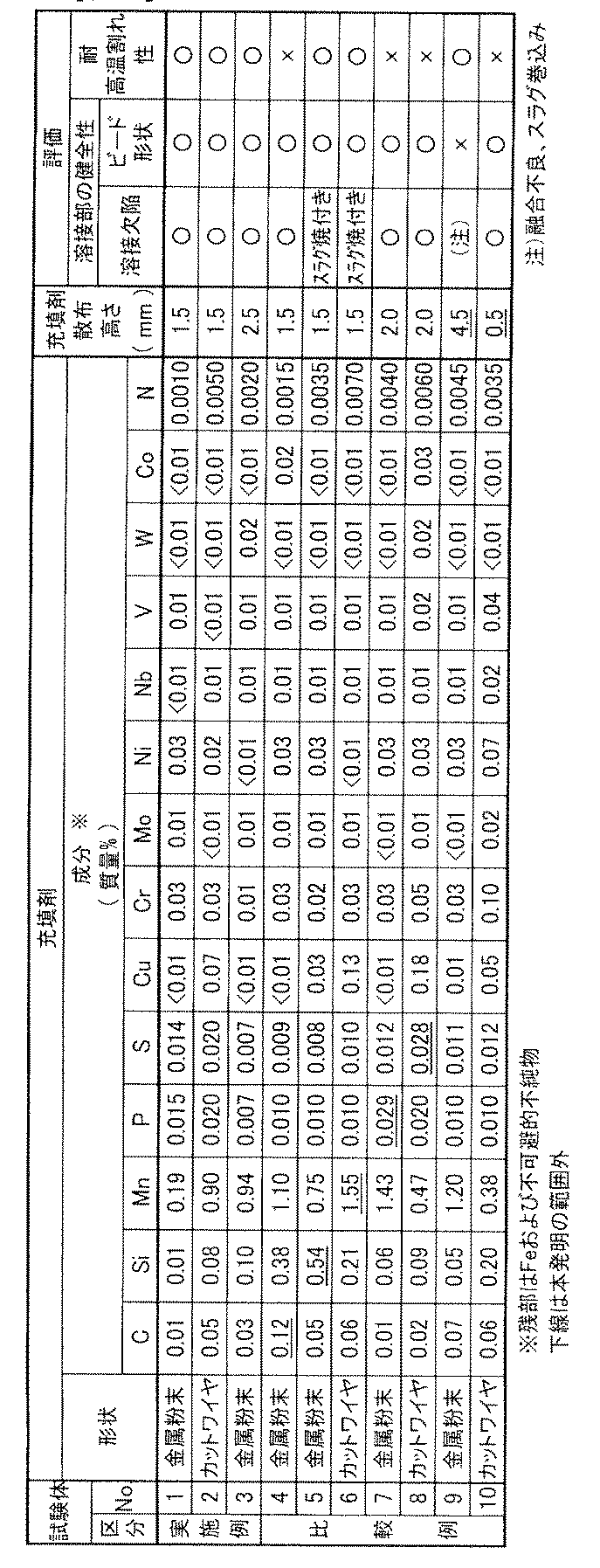
表4に示すように、試験体No.1~3は、充填剤の成分および開先の散布高さが本発明の範囲内であり、溶接部の健全性および耐高温割れ性が良好であった。
これに対して、試験体No.4は、充填剤のC含有量が過剰なため、溶接金属のCの濃化により高温割れが発生した。試験材No.5は充填剤のSi含有量が、試験材No.6は充填剤のMn含有量がそれぞれ過剰なため、スラグ焼付きが発生した。試験材No.7は充填剤のP含有量が、試験材No.8は充填剤のS含有量がそれぞれ過剰なため、高温割れが発生した。
試験体No.9は、充填剤の散布高さが過剰なため、溶接ビード形状が凸ビードとなり、そのために融合不良およびスラグ巻込みが発生した。試験体No.10は、充填剤の散布高さが不足したため、溶接金属のCの濃化を抑制することができず、高温割れが発生した。
本出願は、出願日が2014年7月18日である日本国特許出願、特願第2014-147996号を基礎出願とする優先権主張と伴う。特願第2014-147996号は参照することにより本明細書に取り込まれる。
10 母材(被溶接材)
11 溶接チップ
11a 先行極(溶接チップ)
11b 後行極(溶接チップ)
12,12a,12b 溶接ワイヤ
20 試験体
21 初層溶接金属
21f 充填剤
22 溶接金属
11 溶接チップ
11a 先行極(溶接チップ)
11b 後行極(溶接チップ)
12,12a,12b 溶接ワイヤ
20 試験体
21 初層溶接金属
21f 充填剤
22 溶接金属
Claims (13)
- 高Cr系CSEF鋼を母材とする初層サブマージアーク溶接方法であって、C:0.10質量%以下、Si:0.50質量%以下、Mn:1.50質量%以下、P:0.025質量%以下、S:0.025質量%以下を含有し、残部がFeおよび不可避的不純物からなる金属粉末またはカットワイヤを、前記母材の開先内へ散布高さ1.0~4.0mmに充填して溶接することを特徴とする初層サブマージアーク溶接方法。
- 前記溶接に用いる溶接ワイヤは、C:0.03~0.13質量%、Si:0.05~0.50質量%、Mn:0.50~2.20質量%、P:0.015質量%以下、S:0.010質量%以下、Ni:0.20質量%を超え1.00質量%以下、Cr:8.00~10.50質量%、Mo:0.20~1.20質量%、V:0.05~0.45質量%、Nb:0.020~0.080質量%、N:0.02~0.08質量%を含有し残部がFeおよび不可避的不純物である請求項1に記載の初層サブマージアーク溶接方法。
- 前記溶接ワイヤは、Cu:1.70質量%以下、B:0.005質量%以下、W:2.0質量%以下およびCo:3.0質量%以下からなる群から選択される少なくとも1つ以上をさらに含有する請求項2に記載の初層サブマージアーク溶接方法。
- 前記溶接に用いる溶接フラックスは、以下の式で示される塩基度が1.0~3.3である請求項2または3に記載の初層サブマージアーク溶接方法。
塩基度=(CaF2+CaO+MgO+SrO+Na2O+Li2O+1/2(MnO+FeO))/(SiO2+1/2(Al2O3+TiO2+ZrO2))
ここで、各化合物はフラックス全質量あたりの各化合物の含有量(質量%)を示す - 前記初層サブマージアーク溶接方法が初層シングルサブマージアーク溶接方法であり、ワイヤ送給速度(V)を50~120g/min、溶接速度(v)を20~60cm/minとし、前記ワイヤ送給速度と前記溶接速度との比で求める単位溶接長さ当りの溶着量(V/v)を1.8~4.5g/cmとする条件で溶接する請求項4に記載の初層サブマージアーク溶接方法。
- 前記初層サブマージアーク溶接方法が初層タンデムサブマージアーク溶接方法であり、先行極のワイヤ送給速度VLを45~90g/min、後行極のワイヤ送給速度VTを60~110g/min、溶接速度vを30~55cm/min、単位溶接長さ当りの溶着量を2.8~3.8g/cmとする条件で溶接する請求項4に記載の初層サブマージアーク溶接方法。
- チップ/母材間距離が20~40mmである請求項5に記載の初層サブマージアーク溶接方法。
- チップ角度は、後退角αが0°から60°までの範囲、前進角βが0°から60°までの範囲である請求項7に記載の初層サブマージアーク溶接方法。
- チップ形状は、直管状またはベンド角材状である請求項8に記載の初層サブマージアーク溶接方法。
- チップ/母材間距離が20~40mmである請求項6に記載の初層サブマージアーク溶接方法。
- チップ角度は、後退角αが0°から60°までの範囲、前進角βが0°から60°までの範囲である請求項10に記載の初層サブマージアーク溶接方法。
- チップ形状は、直管状またはベンド角材状である請求項11に記載の初層サブマージアーク溶接方法。
- 前記初層サブマージアーク溶接方法が初層タンデムサブマージアーク溶接方法であり、先行極と後行極との間の極間距離が15mm~25mmである請求項1に記載のタンデム初層サブマージアーク溶接方法。
Priority Applications (1)
| Application Number | Priority Date | Filing Date | Title |
|---|---|---|---|
| CN201580022331.8A CN106232287B (zh) | 2014-07-18 | 2015-07-16 | 高Cr系CSEF钢的初层埋弧焊方法 |
Applications Claiming Priority (2)
| Application Number | Priority Date | Filing Date | Title |
|---|---|---|---|
| JP2014-147996 | 2014-07-18 | ||
| JP2014147996A JP6282191B2 (ja) | 2014-07-18 | 2014-07-18 | 高Cr系CSEF鋼の初層サブマージアーク溶接方法 |
Publications (1)
| Publication Number | Publication Date |
|---|---|
| WO2016010122A1 true WO2016010122A1 (ja) | 2016-01-21 |
Family
ID=55078608
Family Applications (1)
| Application Number | Title | Priority Date | Filing Date |
|---|---|---|---|
| PCT/JP2015/070436 Ceased WO2016010122A1 (ja) | 2014-07-18 | 2015-07-16 | 高Cr系CSEF鋼の初層サブマージアーク溶接方法 |
Country Status (3)
| Country | Link |
|---|---|
| JP (1) | JP6282191B2 (ja) |
| CN (1) | CN106232287B (ja) |
| WO (1) | WO2016010122A1 (ja) |
Cited By (3)
| Publication number | Priority date | Publication date | Assignee | Title |
|---|---|---|---|---|
| TWI677398B (zh) * | 2018-10-24 | 2019-11-21 | 葉均蔚 | 以合金粉末作為焊接填料的焊接方法 |
| JP2022061813A (ja) * | 2020-10-07 | 2022-04-19 | 日本製鉄株式会社 | 溶接継手の製造方法及び開先充填用のフラックス入りカットワイヤ |
| JP2022061805A (ja) * | 2020-10-07 | 2022-04-19 | 日本製鉄株式会社 | 溶接継手の製造方法及び開先充填用のフラックス入りカットワイヤ |
Families Citing this family (4)
| Publication number | Priority date | Publication date | Assignee | Title |
|---|---|---|---|---|
| CN107498145B (zh) * | 2017-07-27 | 2019-07-19 | 江苏省沙钢钢铁研究院有限公司 | 一种堆“埋弧焊熔敷金属试验”过渡层的焊接方法 |
| CN107999997B (zh) * | 2017-11-23 | 2020-06-16 | 青岛武船重工有限公司 | 一种fab法焊接用填充粉 |
| JP7606071B2 (ja) * | 2020-10-07 | 2024-12-25 | 日本製鉄株式会社 | 溶接継手の製造方法及び開先充填用のフラックス入りカットワイヤ |
| JP7804130B1 (ja) * | 2025-05-27 | 2026-01-21 | 川田工業株式会社 | 2電極式サブマージアーク溶接方法及び溶接装置 |
Citations (8)
| Publication number | Priority date | Publication date | Assignee | Title |
|---|---|---|---|---|
| JPS5067758A (ja) * | 1973-10-22 | 1975-06-06 | ||
| JPH01205882A (ja) * | 1988-02-10 | 1989-08-18 | Sumitomo Metal Ind Ltd | 低稀釈多電極サブマージアーク溶接法 |
| JPH0299279A (ja) * | 1988-09-30 | 1990-04-11 | Kobe Steel Ltd | 厚鋼材の製造方法 |
| JPH0639587A (ja) * | 1992-07-23 | 1994-02-15 | Nippon Steel Corp | 高Crフェライト系耐熱鋼用潜弧溶接方法 |
| JPH0994690A (ja) * | 1995-09-29 | 1997-04-08 | Kobe Steel Ltd | 溶接用カットワイヤ |
| JPH10156534A (ja) * | 1996-11-21 | 1998-06-16 | Sumitomo Metal Ind Ltd | スパイラル鋼管の製造方法 |
| JP2005329415A (ja) * | 2004-05-18 | 2005-12-02 | Kobe Steel Ltd | 改良9Cr−1Mo鋼用溶接ワイヤ |
| JP2008264812A (ja) * | 2007-04-18 | 2008-11-06 | Kobe Steel Ltd | サブマージアーク溶接用開先充填材 |
Family Cites Families (7)
| Publication number | Priority date | Publication date | Assignee | Title |
|---|---|---|---|---|
| JPS5668591A (en) * | 1979-11-09 | 1981-06-09 | Mitsubishi Heavy Ind Ltd | Thick-walled material welding method |
| JPH03281066A (ja) * | 1990-03-28 | 1991-12-11 | Nippon Steel Corp | I開先片面溶接方法 |
| JPH11267883A (ja) * | 1998-03-24 | 1999-10-05 | Nippon Steel Corp | 大入熱用570MPa耐候性鋼の片面サブマージアーク溶接用ボンドフラックスおよび片面サブマージアーク溶接方法 |
| JP2006035279A (ja) * | 2004-07-28 | 2006-02-09 | Nippon Steel & Sumikin Welding Co Ltd | 多電極片面サブマージアーク溶接方法 |
| CN100443246C (zh) * | 2007-01-30 | 2008-12-17 | 山东大学 | 堆焊用填充金属颗粒及其制备方法 |
| KR100811920B1 (ko) * | 2007-02-07 | 2008-03-10 | 대우조선해양 주식회사 | 용접 맞대기 이음의 일면 용접방법 |
| CN102152020B (zh) * | 2011-01-31 | 2013-05-08 | 山东博润工业技术股份有限公司 | 一种低碳钢表面粉末埋弧堆焊用涂覆粉末及其应用方法 |
-
2014
- 2014-07-18 JP JP2014147996A patent/JP6282191B2/ja not_active Expired - Fee Related
-
2015
- 2015-07-16 CN CN201580022331.8A patent/CN106232287B/zh not_active Expired - Fee Related
- 2015-07-16 WO PCT/JP2015/070436 patent/WO2016010122A1/ja not_active Ceased
Patent Citations (8)
| Publication number | Priority date | Publication date | Assignee | Title |
|---|---|---|---|---|
| JPS5067758A (ja) * | 1973-10-22 | 1975-06-06 | ||
| JPH01205882A (ja) * | 1988-02-10 | 1989-08-18 | Sumitomo Metal Ind Ltd | 低稀釈多電極サブマージアーク溶接法 |
| JPH0299279A (ja) * | 1988-09-30 | 1990-04-11 | Kobe Steel Ltd | 厚鋼材の製造方法 |
| JPH0639587A (ja) * | 1992-07-23 | 1994-02-15 | Nippon Steel Corp | 高Crフェライト系耐熱鋼用潜弧溶接方法 |
| JPH0994690A (ja) * | 1995-09-29 | 1997-04-08 | Kobe Steel Ltd | 溶接用カットワイヤ |
| JPH10156534A (ja) * | 1996-11-21 | 1998-06-16 | Sumitomo Metal Ind Ltd | スパイラル鋼管の製造方法 |
| JP2005329415A (ja) * | 2004-05-18 | 2005-12-02 | Kobe Steel Ltd | 改良9Cr−1Mo鋼用溶接ワイヤ |
| JP2008264812A (ja) * | 2007-04-18 | 2008-11-06 | Kobe Steel Ltd | サブマージアーク溶接用開先充填材 |
Cited By (5)
| Publication number | Priority date | Publication date | Assignee | Title |
|---|---|---|---|---|
| TWI677398B (zh) * | 2018-10-24 | 2019-11-21 | 葉均蔚 | 以合金粉末作為焊接填料的焊接方法 |
| JP2022061813A (ja) * | 2020-10-07 | 2022-04-19 | 日本製鉄株式会社 | 溶接継手の製造方法及び開先充填用のフラックス入りカットワイヤ |
| JP2022061805A (ja) * | 2020-10-07 | 2022-04-19 | 日本製鉄株式会社 | 溶接継手の製造方法及び開先充填用のフラックス入りカットワイヤ |
| JP7698178B2 (ja) | 2020-10-07 | 2025-06-25 | 日本製鉄株式会社 | 溶接継手の製造方法及び開先充填用のフラックス入りカットワイヤ |
| JP7698179B2 (ja) | 2020-10-07 | 2025-06-25 | 日本製鉄株式会社 | 溶接継手の製造方法及び開先充填用のフラックス入りカットワイヤ |
Also Published As
| Publication number | Publication date |
|---|---|
| JP6282191B2 (ja) | 2018-02-21 |
| CN106232287A (zh) | 2016-12-14 |
| JP2016022502A (ja) | 2016-02-08 |
| CN106232287B (zh) | 2019-07-02 |
Similar Documents
| Publication | Publication Date | Title |
|---|---|---|
| JP6282191B2 (ja) | 高Cr系CSEF鋼の初層サブマージアーク溶接方法 | |
| JP6290024B2 (ja) | 高Cr系CSEF鋼のタンデムサブマージアーク溶接方法 | |
| JP5671364B2 (ja) | クリープ特性に優れた溶接金属 | |
| JP2008161932A (ja) | ワイヤ、フラックス及び高ニッケル含量を有している鋼を溶接するためのプロセス | |
| KR20200079541A (ko) | 가스 실드 아크 용접 와이어 및 가스 실드 아크 용접 방법 | |
| JP6209135B2 (ja) | 狭開先タンデムサブマージアーク溶接方法 | |
| KR102088179B1 (ko) | 서브머지드 아크 용접용 와이어 | |
| JP6290023B2 (ja) | 高Cr系CSEF鋼のシングルサブマージアーク溶接方法 | |
| JP6282190B2 (ja) | 高Cr系CSEF鋼のシングルサブマージアーク溶接方法 | |
| JP6641084B2 (ja) | 溶接時の耐棒焼け性に優れる低水素系被覆アーク溶接棒 | |
| KR101760828B1 (ko) | Ni계 플럭스 코어드 와이어 용접재료 | |
| JP6515324B2 (ja) | 耐sr特性に優れた高強度uoe鋼管のサブマージアーク溶接金属 | |
| CN120035498A (zh) | 实芯焊丝和气体保护电弧焊方法 | |
| JP2024037428A (ja) | ソリッドワイヤ及びガスシールドアーク溶接方法 | |
| JP2018176283A (ja) | 低水素系被覆アーク溶接棒 |
Legal Events
| Date | Code | Title | Description |
|---|---|---|---|
| 121 | Ep: the epo has been informed by wipo that ep was designated in this application |
Ref document number: 15822682 Country of ref document: EP Kind code of ref document: A1 |
|
| NENP | Non-entry into the national phase |
Ref country code: DE |
|
| 122 | Ep: pct application non-entry in european phase |
Ref document number: 15822682 Country of ref document: EP Kind code of ref document: A1 |