WO2016010069A1 - 充電用インレット - Google Patents
充電用インレット Download PDFInfo
- Publication number
- WO2016010069A1 WO2016010069A1 PCT/JP2015/070251 JP2015070251W WO2016010069A1 WO 2016010069 A1 WO2016010069 A1 WO 2016010069A1 JP 2015070251 W JP2015070251 W JP 2015070251W WO 2016010069 A1 WO2016010069 A1 WO 2016010069A1
- Authority
- WO
- WIPO (PCT)
- Prior art keywords
- mounting plate
- fixed
- inlet
- bolt
- collar
- Prior art date
- Legal status (The legal status is an assumption and is not a legal conclusion. Google has not performed a legal analysis and makes no representation as to the accuracy of the status listed.)
- Ceased
Links
Images




Classifications
-
- H—ELECTRICITY
- H01—ELECTRIC ELEMENTS
- H01R—ELECTRICALLY-CONDUCTIVE CONNECTIONS; STRUCTURAL ASSOCIATIONS OF A PLURALITY OF MUTUALLY-INSULATED ELECTRICAL CONNECTING ELEMENTS; COUPLING DEVICES; CURRENT COLLECTORS
- H01R13/00—Details of coupling devices of the kinds covered by groups H01R12/70 or H01R24/00 - H01R33/00
- H01R13/64—Means for preventing incorrect coupling
- H01R13/641—Means for preventing incorrect coupling by indicating incorrect coupling; by indicating correct or full engagement
-
- B—PERFORMING OPERATIONS; TRANSPORTING
- B60—VEHICLES IN GENERAL
- B60L—PROPULSION OF ELECTRICALLY-PROPELLED VEHICLES; SUPPLYING ELECTRIC POWER FOR AUXILIARY EQUIPMENT OF ELECTRICALLY-PROPELLED VEHICLES; ELECTRODYNAMIC BRAKE SYSTEMS FOR VEHICLES IN GENERAL; MAGNETIC SUSPENSION OR LEVITATION FOR VEHICLES; MONITORING OPERATING VARIABLES OF ELECTRICALLY-PROPELLED VEHICLES; ELECTRIC SAFETY DEVICES FOR ELECTRICALLY-PROPELLED VEHICLES
- B60L53/00—Methods of charging batteries, specially adapted for electric vehicles; Charging stations or on-board charging equipment therefor; Exchange of energy storage elements in electric vehicles
- B60L53/10—Methods of charging batteries, specially adapted for electric vehicles; Charging stations or on-board charging equipment therefor; Exchange of energy storage elements in electric vehicles characterised by the energy transfer between the charging station and the vehicle
- B60L53/14—Conductive energy transfer
- B60L53/16—Connectors, e.g. plugs or sockets, specially adapted for charging electric vehicles
-
- H—ELECTRICITY
- H01—ELECTRIC ELEMENTS
- H01R—ELECTRICALLY-CONDUCTIVE CONNECTIONS; STRUCTURAL ASSOCIATIONS OF A PLURALITY OF MUTUALLY-INSULATED ELECTRICAL CONNECTING ELEMENTS; COUPLING DEVICES; CURRENT COLLECTORS
- H01R13/00—Details of coupling devices of the kinds covered by groups H01R12/70 or H01R24/00 - H01R33/00
- H01R13/66—Structural association with built-in electrical component
- H01R13/717—Structural association with built-in electrical component with built-in light source
- H01R13/7175—Light emitting diodes (LEDs)
-
- H—ELECTRICITY
- H01—ELECTRIC ELEMENTS
- H01R—ELECTRICALLY-CONDUCTIVE CONNECTIONS; STRUCTURAL ASSOCIATIONS OF A PLURALITY OF MUTUALLY-INSULATED ELECTRICAL CONNECTING ELEMENTS; COUPLING DEVICES; CURRENT COLLECTORS
- H01R13/00—Details of coupling devices of the kinds covered by groups H01R12/70 or H01R24/00 - H01R33/00
- H01R13/73—Means for mounting coupling parts to apparatus or structures, e.g. to a wall
- H01R13/74—Means for mounting coupling parts in openings of a panel
-
- H—ELECTRICITY
- H01—ELECTRIC ELEMENTS
- H01R—ELECTRICALLY-CONDUCTIVE CONNECTIONS; STRUCTURAL ASSOCIATIONS OF A PLURALITY OF MUTUALLY-INSULATED ELECTRICAL CONNECTING ELEMENTS; COUPLING DEVICES; CURRENT COLLECTORS
- H01R13/00—Details of coupling devices of the kinds covered by groups H01R12/70 or H01R24/00 - H01R33/00
- H01R13/73—Means for mounting coupling parts to apparatus or structures, e.g. to a wall
- H01R13/74—Means for mounting coupling parts in openings of a panel
- H01R13/748—Means for mounting coupling parts in openings of a panel using one or more screws
-
- H—ELECTRICITY
- H02—GENERATION; CONVERSION OR DISTRIBUTION OF ELECTRIC POWER
- H02J—ELECTRIC POWER NETWORKS; CIRCUIT ARRANGEMENTS OR SYSTEMS FOR SUPPLYING OR DISTRIBUTING ELECTRIC POWER; SYSTEMS FOR STORING ELECTRIC ENERGY
- H02J7/00—Circuit arrangements for charging or discharging batteries or for supplying loads from batteries
- H02J7/70—Circuit arrangements for charging or discharging batteries or for supplying loads from batteries characterised by the mechanical construction
-
- H—ELECTRICITY
- H01—ELECTRIC ELEMENTS
- H01R—ELECTRICALLY-CONDUCTIVE CONNECTIONS; STRUCTURAL ASSOCIATIONS OF A PLURALITY OF MUTUALLY-INSULATED ELECTRICAL CONNECTING ELEMENTS; COUPLING DEVICES; CURRENT COLLECTORS
- H01R2201/00—Connectors or connections adapted for particular applications
- H01R2201/26—Connectors or connections adapted for particular applications for vehicles
-
- Y—GENERAL TAGGING OF NEW TECHNOLOGICAL DEVELOPMENTS; GENERAL TAGGING OF CROSS-SECTIONAL TECHNOLOGIES SPANNING OVER SEVERAL SECTIONS OF THE IPC; TECHNICAL SUBJECTS COVERED BY FORMER USPC CROSS-REFERENCE ART COLLECTIONS [XRACs] AND DIGESTS
- Y02—TECHNOLOGIES OR APPLICATIONS FOR MITIGATION OR ADAPTATION AGAINST CLIMATE CHANGE
- Y02T—CLIMATE CHANGE MITIGATION TECHNOLOGIES RELATED TO TRANSPORTATION
- Y02T10/00—Road transport of goods or passengers
- Y02T10/60—Other road transportation technologies with climate change mitigation effect
- Y02T10/70—Energy storage systems for electromobility, e.g. batteries
-
- Y—GENERAL TAGGING OF NEW TECHNOLOGICAL DEVELOPMENTS; GENERAL TAGGING OF CROSS-SECTIONAL TECHNOLOGIES SPANNING OVER SEVERAL SECTIONS OF THE IPC; TECHNICAL SUBJECTS COVERED BY FORMER USPC CROSS-REFERENCE ART COLLECTIONS [XRACs] AND DIGESTS
- Y02—TECHNOLOGIES OR APPLICATIONS FOR MITIGATION OR ADAPTATION AGAINST CLIMATE CHANGE
- Y02T—CLIMATE CHANGE MITIGATION TECHNOLOGIES RELATED TO TRANSPORTATION
- Y02T10/00—Road transport of goods or passengers
- Y02T10/60—Other road transportation technologies with climate change mitigation effect
- Y02T10/7072—Electromobility specific charging systems or methods for batteries, ultracapacitors, supercapacitors or double-layer capacitors
-
- Y—GENERAL TAGGING OF NEW TECHNOLOGICAL DEVELOPMENTS; GENERAL TAGGING OF CROSS-SECTIONAL TECHNOLOGIES SPANNING OVER SEVERAL SECTIONS OF THE IPC; TECHNICAL SUBJECTS COVERED BY FORMER USPC CROSS-REFERENCE ART COLLECTIONS [XRACs] AND DIGESTS
- Y02—TECHNOLOGIES OR APPLICATIONS FOR MITIGATION OR ADAPTATION AGAINST CLIMATE CHANGE
- Y02T—CLIMATE CHANGE MITIGATION TECHNOLOGIES RELATED TO TRANSPORTATION
- Y02T90/00—Enabling technologies or technologies with a potential or indirect contribution to GHG emissions mitigation
- Y02T90/10—Technologies relating to charging of electric vehicles
- Y02T90/14—Plug-in electric vehicles
Definitions
- the technology disclosed in this specification relates to a charging inlet.
- a charging connector for charging a battery by coupling a power feeding side connector to a power receiving side connector for example, one disclosed in Japanese Patent Laid-Open No. 2012-181984 (Patent Document 1 below) is known.
- Patent Document 1 Japanese Patent Laid-Open No. 2012-181984
- the power receiving side connector and the lighting unit are arranged side by side, and each is bolted to the body.
- the power receiving side connector and the lighting unit are provided separately, so that the installation space on the body side becomes large.
- the work for fastening to the body increases, and the number of fastening parts also increases. Therefore, if the lighting unit is not attached to the body but is attached to the power receiving side connector in advance, the installation space on the body side is reduced and the fastening work to the body is reduced.
- the fastening portion to the body needs to be configured by a cylindrical metal part (a part called by a name such as a metal collar), and when the illumination unit is previously attached to the power receiving side connector as described above, the illumination unit A configuration is conceivable in which metal parts are set on both the power receiving side connector and the power receiving side connector and are fastened to the body in a state where these are inserted into one bolt.
- a cylindrical metal part a part called by a name such as a metal collar
- the charging inlet disclosed in the present specification includes a first mounting plate that is attached to a body of a vehicle, an inlet main body having a fixed portion provided on the first mounting plate, the body, and the first mounting.
- a second mounting plate disposed between the plates and provided with a through hole; and a fixed portion to which the fixed portion is fixed, and the fixed portion is fixed to the fixed portion, thereby
- a metal fixing part that fixes the inlet body to the body in a state where the end of the cylindrical part is in contact with the body.
- a metal cylindrical part that contacts the body may be provided only on the first mounting plate, and only a through hole is provided on the second mounting plate. Therefore, it is possible to prevent an increase in the number of parts of the cylindrical part. Further, when the cylindrical part is passed through the through hole, the fixed portion is easily positioned on the fixed portion, and the work of fixing the fixed portion to the fixed portion and attaching the display plate to the inlet body is facilitated.
- the charging inlet disclosed in the present specification may have the following configuration.
- the inlet body may have a connector fitting portion, and the display plate may have a display portion arranged around the connector fitting portion.
- the display unit is arranged around the connector fitting unit, so that the display unit-integrated charging inlet is configured. Therefore, the display unit is not attached to the body separately from the charging inlet. The installation space on the body side may be reduced.
- the fixed component may be configured by a bolt having the shaft portion and a nut to which the bolt can be screwed.
- an inlet main body can be fixed to a body by screwing a volt
- the bolt may be configured to be fixed to the body. According to such a configuration, it is not necessary to hold the bolt by hand, and it is only necessary to screw the nut through the cylindrical part to the bolt fixed to the body.
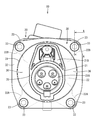
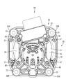
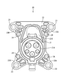
- FIG. 1 Front view of charging inlet AA line sectional view in FIG. Rear view of charging inlet Front view of display plate Rear view of display plate Front view of inlet body Rear view of the inlet body
- the charging inlet 10 in the present embodiment includes an inlet body 20 shown in FIG. 6 and a display plate 30 shown in FIG.
- the inlet main body 20 has a connector fitting portion 21 into which a charging gun provided on the power supply side (not shown) can be fitted.
- This charging inlet 10 is fixed to the body B of the vehicle.
- the side of the connector fitting portion 21 that is fitted with the charging gun is referred to as the front side.
- the connector fitting portion 21 includes a terminal connection portion 21A to which the terminal portion of the charging gun is connected, and a lock connection portion 21B to which the lock portion of the charging gun is connected.
- the terminal connection portion 21A has a cylindrical peripheral wall, and the lock connection portion 21B is provided in a form that protrudes upward from the upper surface of the peripheral wall in a gate shape.
- the inlet body 20 includes a first mounting plate 22 that projects to the outer peripheral side of the connector fitting portion 21.
- the first mounting plate 22 is configured to project radially from the connector fitting portion 21 as a center, a pair of left and right flange portions 22A projecting obliquely downward from the terminal connection portion 21A, and both left and right sides from the lock connection portion 21B. It consists of a pair of left and right flange portions 22B.
- a metal long collar 23 is fixed to the front end of each flange 22A, 22B.
- a metal short collar 24 is similarly fixed to the base end of each flange 22A, 22B. Both the long collar 23 and the short collar 24 are configured to penetrate the first mounting plate 22 in the thickness direction, and the dimension in the front-rear direction is longer than the thickness of the first mounting plate 22.
- the long collar 23 and the short collar 24 are integrally formed by insert molding on the first mounting plate 22.
- the display plate 30 includes a display unit 31 having an accommodation hole 35 in which the connector fitting unit 21 is accommodated, and a second mounting plate 32 that projects to the outer peripheral side of the display unit 31. It is configured.
- the display unit 31 has a substantially circular shape, and a charging indicator 36 that displays a charging state or the like is provided between the hole edge of the accommodation hole 35 and the outer peripheral edge of the display unit 31.
- a plurality of screwing portions 37 for screwing an LED unit are provided on the rear surface side of the second mounting plate 32.
- the charging indicator 36 is lit by irradiating light forward from the LED unit.
- fixing nuts 34 are fixed to the rear surface side of the display unit 31 by fixing means such as press fitting. These fixing nuts 34 are arranged at positions closer to the accommodation holes 35 than the screwing portions 37 in the left-right direction.
- the second mounting plate 32 has a substantially square shape as a whole as shown in FIG. At the four corners of the second mounting plate 32, through holes 33 are respectively provided so as to penetrate in the thickness direction. As shown in FIG. 1, when the display plate 30 is attached to the inlet body 20 from the front, the through-hole 33 is arranged through the long collar 23. That is, as shown in FIG. 2, the long collar 23 is fixed to the first mounting plate 22 so as to protrude forward from the front surface of the first mounting plate 22. The protruding portion of the long collar 23 is inserted through the through-hole 33 from behind, and the front end portion 23A of the long collar 23 contacts the body B through the through-hole 33.
- the bolt 40 is erected on the rear surface of the body B so as to protrude rearward.
- the bolt 40 of the present embodiment is a stud bolt that is fixed to the body B in advance, and has a shaft portion 41.
- the shaft portion 41 is inserted into the long collar 23 from the front, and the nut 50 is screwed into a portion protruding rearward from the long collar 23.
- the nut 50 is screwed onto the shaft portion 41, the nut 50 comes into contact with the rear end portion of the long collar 23, and the front end portion 23A of the long collar 23 comes into contact with the rear surface of the body B.
- the long collar 23 is sandwiched between the rear surface and the inlet main body 20 and the body B are fixed by metal touch.
- a mounting bolt 60 is inserted into the short collar 24 of the inlet body 20 from the rear, and a portion protruding forward from the short collar 24 is screwed into the fixing nut 34 of the display plate 30.
- the front end portion of the short collar 24 comes into contact with the rear surface of the fixing nut 34, and the inlet body 20 and the display plate 30 are fixed by metal touch.
- the inlet 10 for charge is comprised.
- the second mounting plate 32 of the display plate 30 is not in contact with the rear surface of the body B when the inlet body 20 is fixed to the body B.
- the outer diameter of the long collar 23 is slightly smaller than the inner diameter of the through hole 33.
- the clearance between the outer peripheral surface of the long collar 23 and the inner peripheral surface of the through hole 33 is set to be smaller than the mounting tolerance for attaching the short collar 24 to the fixing nut 34. Therefore, by inserting the plurality of long collars 23 into the plurality of through holes 33, the short collar 24 can be attached to the fixing nut 34, and the inlet body 20 and the display plate 30 are temporarily assembled in a regular assembly posture. be able to. Therefore, the operation of inserting the mounting bolt 60 into the short collar 24 and screwing it onto the fixing nut 34 is facilitated.
- each long collar 23 passes through the through hole 33 of the second mounting plate 32 and the front end portion 23A slightly protrudes forward, so that the charging inlet 10 is configured.
- each bolt 40 penetrates each long collar 23 and protrudes rearward.
- each nut 50 is screwed into each bolt 40, each nut N comes into contact with the rear end portion of each long collar 23, and the front end portion 23A of each long collar 23 comes into contact with the body B.
- the screwing of each nut 50 is stopped.
- the charging inlet 10 is fixed to the body B by metal touch.
- a metallic cylindrical part that contacts the body B (for example, a part commonly referred to as a collar or the like and the long collar 23 of the present embodiment) is provided only on the first mounting plate 22. What is necessary is just to provide the 2nd attachment plate 32 with the through-hole 33, Therefore It can prevent that the number of parts of a cylindrical part increases. Further, when the cylindrical part is passed through the through hole 33, the fixed portion (short collar 24) is easily positioned on the fixing portion (fixing nut 34), and the display plate 30 is fixed by fixing the fixed portion to the fixing portion. The work of attaching to the inlet body 20 is facilitated.
- the inlet body 20 may have a connector fitting portion 21, and the display plate 30 may have a display portion 31 arranged around the connector fitting portion 21.
- the display unit 31 is integrated with the charging inlet 10 by arranging the display unit 31 around the connector fitting unit 21, so that the display unit 31 is connected to the charging inlet 10. In addition, it does not have to be attached to the body B, and the installation space on the body B side is reduced.
- the fixed component may be configured by a bolt 40 having a shaft portion 41 and a nut 50 to which the bolt 40 can be screwed. According to such a configuration, the inlet body 20 can be fixed to the body B by screwing the bolt 40 into the nut 50.
- the bolt 40 may be configured to be fixed to the body B. According to such a configuration, it is not necessary to hold the bolt 40 by hand, and the nut 50 can be screwed through the cylindrical part to the bolt 40 fixed to the body B. It becomes easy to do.
- a plurality of cylindrical parts may be provided on the peripheral edge of the first mounting plate 22, and a plurality of through holes 33 may be provided on the peripheral edge of the second mounting plate 32. According to such a configuration, since a plurality of cylindrical parts can be penetrated through the plurality of through holes 33, the fixed portion can be accurately positioned on the fixed portion.
- the second mounting plate 32 is disposed on the front side of the first mounting plate 22 in the above embodiment, the second mounting plate may be disposed on the rear side of the first mounting plate.
- cylindrical long collar 23 is exemplified as the cylindrical part, but a rectangular metal collar may be used as the cylindrical part.
- the display portion 31 is arranged around the connector fitting portion 21, the connector fitting portion and the display portion may be arranged side by side. .
- the bolt and the nut are illustrated as the fixing parts, a pair of nuts are screwed into one shaft portion so that the long collar 24 is sandwiched between the pair of nuts. May be.
- the bolt may not be a stud bolt fixed to the body B, and a bolt hole may be provided in the body, and the bolt may be inserted into the bolt hole from the front.
- the short collar 24 is exemplified as the fixing portion
- the fixing nut 34 is exemplified as the fixed portion
- the short collar 24 is fixed to the fixing nut 34 by the mounting bolt 60, but the tapping screw is used. You may make it screw directly in the 2nd attachment board 32 (fixed part).
- SYMBOLS 10 Charging inlet 20 ... Inlet main body 21 ... Connector fitting part 22 ... 1st attachment plate 23 ... Long collar (tubular part) 23A ... Front end 24 ... Short collar (fixed part) DESCRIPTION OF SYMBOLS 30 ... Display plate 31 ... Display part 32 ... 2nd mounting plate 33 ... Through-hole 34 ... Fixing nut (fixing part) 40 ... Bolt (fixed part) 41 ... Shaft 50 ... Nut (fixed part) 60 ... Mounting bolt B ... Body
Landscapes
- Engineering & Computer Science (AREA)
- Power Engineering (AREA)
- Physics & Mathematics (AREA)
- Microelectronics & Electronic Packaging (AREA)
- Optics & Photonics (AREA)
- Transportation (AREA)
- Mechanical Engineering (AREA)
- Charge And Discharge Circuits For Batteries Or The Like (AREA)
- Electric Propulsion And Braking For Vehicles (AREA)
- Lighting Device Outwards From Vehicle And Optical Signal (AREA)
- Secondary Cells (AREA)
- Details Of Connecting Devices For Male And Female Coupling (AREA)
Abstract
本発明の充電用インレット(10)は、車両のボディ(B)に取り付けられる第1取付板(22)を有し、この第1取付板(22)に被固定部(ショートカラー(24))が設けられたインレット本体(20)と、ボディ(B)と第1取付板(22)の間に配されて貫通孔(33)が設けられた第2取付板(32)を有し、かつ、被固定部(24)が固定される固定部(固定ナット(34))を有し、この固定部(34)に被固定部(24)が固定されることでインレット本体(20)に取り付けられる表示プレート(30)と、第1取付板(22)からボディ(B)側に突出して設けられ、第2取付板(32)の貫通孔(33)を貫通する金属製の筒状部品(ロングカラー(23))と、筒状部品(23)の内部に挿通される軸部(41)を有し、筒状部品(23)の端部(23A)をボディ(B)に接触させた状態でインレット本体(20)をボディ(B)に固定する金属製の固定部品(ボルト(40)、ナット(50))とを備えている。
Description
本明細書によって開示される技術は、充電用インレットに関する。
従来、給電側コネクタを受電側コネクタに結合することでバッテリーへの充電を行う充電コネクタとして、例えば特開2012-181984号公報(下記特許文献1)に記載のものが知られている。この充電コネクタでは、受電側コネクタと照明ユニットが横並びに配設されて、それぞれがボディにボルト締結されている。
上記の充電コネクタでは、受電側コネクタと照明ユニットが別々に設けられているため、ボディ側の設置スペースが大きくなってしまう。また、受電側コネクタと照明ユニットをボディに対して別々にボルト締結する必要があるため、ボディへの締結作業が多くなり、締結部品の数も多くなる。そこで、照明ユニットをボディに取り付けるのではなく、予め受電側コネクタに取り付けるようにしておけば、ボディ側の設置スペースが小さくなり、ボディへの締結作業が少なくなる。
しかしながら、ボディへの締結部は円筒状の金属部品(金属カラー等の称呼で呼ばれる部品)によって構成する必要があり、上記のように照明ユニットを予め受電側コネクタに取り付けるようにした場合、照明ユニットと受電側コネクタの双方に金属部品を設定しこれらを1本のボルトに挿通した状態でボディに締結する構成が考えられる。ところが、この構成では、1本のボルトに2つの金属部品が必要になるため、部品点数が増加してしまう。
本明細書によって開示される充電用インレットは、車両のボディに取り付けられる第1取付板を有し、この第1取付板に被固定部が設けられたインレット本体と、前記ボディと前記第1取付板の間に配されて貫通孔が設けられた第2取付板を有し、かつ、前記被固定部が固定される固定部を有し、この固定部に前記被固定部が固定されることで前記インレット本体に取り付けられる表示プレートと、前記第1取付板から前記ボディ側に突出して設けられ、前記第2取付板の前記貫通孔を貫通する金属製の筒状部品と、前記筒状部品の内部に挿通される軸部を有し、前記筒状部品の端部を前記ボディに接触させた状態で前記インレット本体を前記ボディに固定する金属製の固定部品とを備えた構成とした。
このような構成によると、ボディに接触する金属製の筒状部品(例えばカラー等の称呼で呼ばれる部品)を第1取付板だけに設ければよく、第2取付板には貫通孔を設けるだけでよいから、筒状部品の部品点数が増加することを防止できる。また、筒状部品を貫通孔に貫通させると、被固定部を固定部に位置決めしやすくなり、被固定部を固定部に固定して表示プレートをインレット本体に取り付ける作業がしやすくなる。
本明細書によって開示される充電用インレットは、以下の構成としてもよい。
前記インレット本体は、コネクタ嵌合部を有し、前記表示プレートは、前記コネクタ嵌合部の周囲に配される表示部を有する構成としてもよい。
このような構成によると、コネクタ嵌合部の周囲に表示部が配されることで、表示部一体型の充電用インレットが構成されるため、表示部を充電用インレットとは別にボディに取り付けなくてもよく、ボディ側の設置スペースが小さくなる。
前記インレット本体は、コネクタ嵌合部を有し、前記表示プレートは、前記コネクタ嵌合部の周囲に配される表示部を有する構成としてもよい。
このような構成によると、コネクタ嵌合部の周囲に表示部が配されることで、表示部一体型の充電用インレットが構成されるため、表示部を充電用インレットとは別にボディに取り付けなくてもよく、ボディ側の設置スペースが小さくなる。
前記固定部品は、前記軸部を有するボルトと、前記ボルトが螺合可能なナットとからなる構成としてもよい。
このような構成によると、ボルトをナットに螺合することでインレット本体をボディに固定できる。
このような構成によると、ボルトをナットに螺合することでインレット本体をボディに固定できる。
前記ボルトは、前記ボディに固定されている構成としてもよい。
このような構成によると、ボルトを手で持つ必要がなく、ボディに固定されたボルトに対して筒状部品を通してナットを螺合させればよいため、インレット本体の固定作業がしやすくなる。
このような構成によると、ボルトを手で持つ必要がなく、ボディに固定されたボルトに対して筒状部品を通してナットを螺合させればよいため、インレット本体の固定作業がしやすくなる。
複数の前記筒状部品が前記第1取付板の周縁部に設けられており、複数の前記貫通孔が前記第2取付板の周縁部に設けられている構成としてもよい。
このような構成によると、複数の筒状部品を複数の貫通孔に貫通させることができるため、被固定部を固定部に精度良く位置決めすることができる。
このような構成によると、複数の筒状部品を複数の貫通孔に貫通させることができるため、被固定部を固定部に精度良く位置決めすることができる。
本明細書によって開示される充電用インレットによれば、筒状部品の部品点数が増加することを防止できる。
<実施形態>
実施形態を図1から図7の図面を参照しながら説明する。本実施形態における充電用インレット10は、図6に示すインレット本体20と、図4に示す表示プレート30とを備えて構成されている。インレット本体20は、図示しない給電器側に設けられた充電ガンが嵌合可能なコネクタ嵌合部21を有している。この充電用インレット10は、車両のボディBに固定されている。なお、以下の説明においてはコネクタ嵌合部21における充電ガンと嵌合する側を前側とする。
実施形態を図1から図7の図面を参照しながら説明する。本実施形態における充電用インレット10は、図6に示すインレット本体20と、図4に示す表示プレート30とを備えて構成されている。インレット本体20は、図示しない給電器側に設けられた充電ガンが嵌合可能なコネクタ嵌合部21を有している。この充電用インレット10は、車両のボディBに固定されている。なお、以下の説明においてはコネクタ嵌合部21における充電ガンと嵌合する側を前側とする。
コネクタ嵌合部21は、充電ガンの端子部が接続される端子接続部21Aと、充電ガンのロック部が接続されるロック接続部21Bとを備えて構成されている。端子接続部21Aは円筒状をなす周壁を有し、この周壁の上面から門形をなして上方に突出する形態でロック接続部21Bが設けられている。また、インレット本体20は、コネクタ嵌合部21の外周側に張り出す第1取付板22を備えている。この第1取付板22は、コネクタ嵌合部21を中心として放射状に突出する形態をなし、端子接続部21Aから斜め下方に張り出す左右一対のフランジ部22Aと、ロック接続部21Bから左右両側に張り出す左右一対のフランジ部22Bとからなる。
各フランジ部22A、22Bの先端部には、金属製のロングカラー23が固定されている。一方、各フランジ部22A、22Bの基端部には、同じく金属製のショートカラー24が固定されている。ロングカラー23とショートカラー24は、いずれも第1取付板22を板厚方向に貫通する形態をなし、前後方向の寸法が第1取付板22の板厚よりも長い寸法とされている。なお、ロングカラー23とショートカラー24は、第1取付板22にインサート成形されることで一体に構成されている。
表示プレート30は、図4に示すように、コネクタ嵌合部21が収容される収容孔35を有する表示部31と、この表示部31の外周側に張り出す第2取付板32とを備えて構成されている。表示部31は略円形とされ、収容孔35の孔縁と表示部31の外周縁との間に、充電状態等を表示する充電インジケータ36が設けられている。第2取付板32の後面側には、図5に示すように、図示しないLEDユニットをねじ止めするための複数のねじ止め部37が設けられている。このLEDユニットから前方に光を照射することで充電インジケータ36が点灯するようになっている。コネクタ嵌合部21を収容孔35に収容すると、図1に示すように、コネクタ嵌合部21の周囲に表示部31が配される。
また、表示部31の後面側には、複数の固定ナット34が圧入等の固定手段によって固定されている。これらの固定ナット34は、左右方向において各ねじ止め部37よりも収容孔35に近い位置に配されている。
第2取付板32は、図4に示すように、全体として略正方形状とされている。第2取付板32の四隅には、それぞれ貫通孔33が板厚方向に貫通して設けられている。この貫通孔33は、図1に示すように、表示プレート30をインレット本体20に前方から取り付けた際に、ロングカラー23が貫通して配されるようになっている。つまり、図2に示すように、ロングカラー23は、第1取付板22の前面から前方に突出する態様で第1取付板22に固定されている。このロングカラー23の突出部分が貫通孔33に後方から挿通されるようになっており、貫通孔33を通り越してロングカラー23の前端部23AがボディBに接触するようになっている。
ボディBの後面には、ボルト40が後方に突出する形態で立設されている。本実施形態のボルト40は、予めボディBに固定されたスタッドボルトとされ、軸部41を有している。この軸部41がロングカラー23に前方から挿入され、ロングカラー23から後方に突出した部分にナット50が螺合するようになっている。ナット50を軸部41に螺合していくと、ナット50がロングカラー23の後端部に当接し、ロングカラー23の前端部23AがボディBの後面に当接し、ナット50とボディBの後面との間にロングカラー23が挟持されることで、インレット本体20とボディBがメタルタッチで固定される。
図3に示すように、インレット本体20のショートカラー24には、取付ボルト60が後方から挿入され、ショートカラー24から前方に突出した部分が表示プレート30の固定ナット34に螺合している。この螺合に伴って、ショートカラー24の前端部が固定ナット34の後面に当接し、インレット本体20と表示プレート30がメタルタッチで固定される。これにより、充電用インレット10が構成される。また、図2に示すように、インレット本体20がボディBに固定された状態では、表示プレート30の第2取付板32がボディBの後面に接触しないものとされている。
ロングカラー23の外径寸法は、貫通孔33の内径寸法よりもやや小さめとされている。ロングカラー23の外周面と貫通孔33の内周面との間のクリアランスは、ショートカラー24を固定ナット34に取り付ける取付公差よりも小さめに設定されている。したがって、複数のロングカラー23を複数の貫通孔33に挿入することで、ショートカラー24を固定ナット34に取り付け可能な状態となり、インレット本体20と表示プレート30を正規の組付け姿勢で仮組みすることができる。したがって、取付ボルト60をショートカラー24に挿通させて固定ナット34に螺合する作業がしやすくなる。
本実施形態は以上のような構成であって、続いてその作用を説明する。まず、インレット本体20と表示プレート30の組み付け方法について説明する。インレット本体20の前方に表示プレート30を配しておき、コネクタ嵌合部21を収容孔35に後方から挿入していくと、各ロングカラー23が各貫通孔33に後方から進入していく。コネクタ嵌合部21が収容孔35に完全に収容された状態になると、各ロングカラー23が各貫通孔33に完全に収容された状態となり、各ショートカラー24と各固定ナット34がほぼ同軸に配された状態となって、インレット本体20と表示プレート30が仮組みされた状態で位置決めされる。
次に、仮組みされたインレット本体20と表示プレート30に対して、各ショートカラー24にそれぞれ取付ボルト60を挿入して、各固定ナット34に螺合し固定することで表示プレート30をインレット本体20に取り付け固定する。これにより、各ロングカラー23は第2取付板32の貫通孔33を貫通し前端部23Aが前方にわずかに突出した状態となって充電用インレット10が構成される。
この後、充電用インレット10を車両のボディBに対して後方から組み付けると、各ボルト40が各ロングカラー23を貫通して後方に突出した状態となる。ここで、各ボルト40に各ナット50を螺合していくと、各ナットNが各ロングカラー23の後端部に当接するとともに、各ロングカラー23の前端部23AがボディBに当接した状態となって各ナット50の螺合が停止される。こうして、充電用インレット10がボディBに対してメタルタッチで固定される。
以上のように本実施形態では、ボディBに接触する金属製の筒状部品(例えばカラー等の通称で呼ばれる部品であって本実施形態のロングカラー23)を第1取付板22だけに設ければよく、第2取付板32には貫通孔33を設けるだけでよいから、筒状部品の部品点数が増加することを防止できる。また、筒状部品を貫通孔33に貫通させると、被固定部(ショートカラー24)を固定部(固定ナット34)に位置決めしやすくなり、被固定部を固定部に固定して表示プレート30をインレット本体20に取り付ける作業がしやすくなる。
インレット本体20は、コネクタ嵌合部21を有し、表示プレート30は、コネクタ嵌合部21の周囲に配される表示部31を有する構成としてもよい。
このような構成によると、コネクタ嵌合部21の周囲に表示部31が配されることで、表示部31一体型の充電用インレット10が構成されるため、表示部31を充電用インレット10とは別にボディBに取り付けなくてもよく、ボディB側の設置スペースが小さくなる。
このような構成によると、コネクタ嵌合部21の周囲に表示部31が配されることで、表示部31一体型の充電用インレット10が構成されるため、表示部31を充電用インレット10とは別にボディBに取り付けなくてもよく、ボディB側の設置スペースが小さくなる。
固定部品は、軸部41を有するボルト40と、ボルト40が螺合可能なナット50とからなる構成としてもよい。
このような構成によると、ボルト40をナット50に螺合することでインレット本体20をボディBに固定できる。
このような構成によると、ボルト40をナット50に螺合することでインレット本体20をボディBに固定できる。
ボルト40は、ボディBに固定されている構成としてもよい。
このような構成によると、ボルト40を手で持つ必要がなく、ボディBに固定されたボルト40に対して筒状部品を通してナット50を螺合させればよいため、インレット本体20の固定作業がしやすくなる。
このような構成によると、ボルト40を手で持つ必要がなく、ボディBに固定されたボルト40に対して筒状部品を通してナット50を螺合させればよいため、インレット本体20の固定作業がしやすくなる。
複数の筒状部品が第1取付板22の周縁部に設けられており、複数の貫通孔33が第2取付板32の周縁部に設けられている構成としてもよい。
このような構成によると、複数の筒状部品を複数の貫通孔33に貫通させることができるため、被固定部を固定部に精度良く位置決めすることができる。
このような構成によると、複数の筒状部品を複数の貫通孔33に貫通させることができるため、被固定部を固定部に精度良く位置決めすることができる。
本明細書によって開示される技術は上記記述及び図面によって説明した実施形態に限定されるものではなく、例えば次のような種々の態様も含まれる。
(1)上記実施形態では、第2取付板32が第1取付板22の前側に配されているものの、第2取付板が第1取付板の後側に配されるものとしてもよい。
(1)上記実施形態では、第2取付板32が第1取付板22の前側に配されているものの、第2取付板が第1取付板の後側に配されるものとしてもよい。
(2)上記実施形態では、筒状部品として円筒状のロングカラー23が例示されているものの、角筒状の金属カラーを筒状部品としてもよい。
(3)上記実施形態では、コネクタ嵌合部21の周囲に表示部31が配されているものを例示しているものの、コネクタ嵌合部と表示部が横並びに配されているものとしてもよい。
(4)上記実施形態では、固定部品としてボルトとナットを例示しているものの、1本の軸部に一対のナットを螺合させ、一対のナットの間にロングカラー24が挟持されるようにしてもよい。また、ボルトはボディBに固定されたスタッドボルトでなくてもよく、ボディにボルト孔を設けて、このボルト孔に前方からボルトを挿通させてもよい。
(5)上記実施形態では、固定部としてショートカラー24を例示し、被固定部として固定ナット34を例示し、取付ボルト60によってショートカラー24を固定ナット34に固定しているものの、タッピングねじを第2取付板32(被固定部)に直接ねじ込むようにしてもよい。
(6)上記実施形態では、第1取付板22の四隅に4つのロングカラー23が固定されているものの、第2取付板22の対角をなす位置に2つのロングカラー23を固定してもよい。
10…充電用インレット
20…インレット本体
21…コネクタ嵌合部
22…第1取付板
23…ロングカラー(筒状部品)
23A…前端部
24…ショートカラー(被固定部)
30…表示プレート
31…表示部
32…第2取付板
33…貫通孔
34…固定ナット(固定部)
40…ボルト(固定部品)
41…軸部
50…ナット(固定部品)
60…取付ボルト
B…ボディ
20…インレット本体
21…コネクタ嵌合部
22…第1取付板
23…ロングカラー(筒状部品)
23A…前端部
24…ショートカラー(被固定部)
30…表示プレート
31…表示部
32…第2取付板
33…貫通孔
34…固定ナット(固定部)
40…ボルト(固定部品)
41…軸部
50…ナット(固定部品)
60…取付ボルト
B…ボディ
Claims (5)
- 車両のボディに取り付けられる第1取付板を有し、この第1取付板に被固定部が設けられたインレット本体と、
前記ボディと前記第1取付板の間に配されて貫通孔が設けられた第2取付板を有し、かつ、前記被固定部が固定される固定部を有し、この固定部に前記被固定部が固定されることで前記インレット本体に取り付けられる表示プレートと、
前記第1取付板から前記ボディ側に突出して設けられ、前記第2取付板の前記貫通孔を貫通する金属製の筒状部品と、
前記筒状部品の内部に挿通される軸部を有し、前記筒状部品の端部を前記ボディに接触させた状態で前記インレット本体を前記ボディに固定する金属製の固定部品とを備えた充電用インレット。 - 前記インレット本体は、コネクタ嵌合部を有し、前記表示プレートは、前記コネクタ嵌合部の周囲に配される表示部を有する請求項1に記載の充電用インレット。
- 前記固定部品は、前記軸部を有するボルトと、前記ボルトが螺合可能なナットとからなる請求項1または請求項2に記載の充電用インレット。
- 前記ボルトは、前記ボディに固定されている請求項3に記載の充電用インレット。
- 複数の前記筒状部品が前記第1取付板の周縁部に設けられており、複数の前記貫通孔が前記第2取付板の周縁部に設けられている請求項1から請求項4のいずれか一項に記載の充電用インレット。
Priority Applications (2)
| Application Number | Priority Date | Filing Date | Title |
|---|---|---|---|
| DE112015003308.4T DE112015003308B4 (de) | 2014-07-17 | 2015-07-15 | Ladestecker |
| US15/320,913 US9755367B2 (en) | 2014-07-17 | 2015-07-15 | Charging inlet |
Applications Claiming Priority (2)
| Application Number | Priority Date | Filing Date | Title |
|---|---|---|---|
| JP2014-146531 | 2014-07-17 | ||
| JP2014146531A JP6172075B2 (ja) | 2014-07-17 | 2014-07-17 | 充電用インレット |
Publications (1)
| Publication Number | Publication Date |
|---|---|
| WO2016010069A1 true WO2016010069A1 (ja) | 2016-01-21 |
Family
ID=55078558
Family Applications (1)
| Application Number | Title | Priority Date | Filing Date |
|---|---|---|---|
| PCT/JP2015/070251 Ceased WO2016010069A1 (ja) | 2014-07-17 | 2015-07-15 | 充電用インレット |
Country Status (4)
| Country | Link |
|---|---|
| US (1) | US9755367B2 (ja) |
| JP (1) | JP6172075B2 (ja) |
| DE (1) | DE112015003308B4 (ja) |
| WO (1) | WO2016010069A1 (ja) |
Families Citing this family (7)
| Publication number | Priority date | Publication date | Assignee | Title |
|---|---|---|---|---|
| JP2018085172A (ja) * | 2016-11-21 | 2018-05-31 | 住友電装株式会社 | 充電用インレット |
| TWM568526U (zh) * | 2018-05-31 | 2018-10-11 | 正崴精密工業股份有限公司 | 電動車充電連接器總成 |
| IT201800006615A1 (it) * | 2018-06-25 | 2019-12-25 | Gruppo di connettore elettrico di ingresso per la ricarica di un veicolo elettrico o di un veicolo ibrido | |
| JP7107859B2 (ja) * | 2019-01-25 | 2022-07-27 | トヨタ自動車株式会社 | 充電インレットの固定構造 |
| CN210430179U (zh) * | 2019-08-15 | 2020-04-28 | 东莞富强电子有限公司 | 电动车插座连接器装置 |
| AT523134B1 (de) * | 2019-11-11 | 2022-02-15 | Neutrik Ag | Einbausteckverbinder |
| IT202100002699A1 (it) | 2021-02-08 | 2022-08-08 | Te Connectivity Italia Distribution Srl | Sistema modulare di illuminazione per prese di alimentazione |
Citations (4)
| Publication number | Priority date | Publication date | Assignee | Title |
|---|---|---|---|---|
| JP2012181984A (ja) * | 2011-03-01 | 2012-09-20 | Yazaki Corp | 照明ユニット及び充電コネクタの照明構造 |
| JP2012221613A (ja) * | 2011-04-05 | 2012-11-12 | Sumitomo Wiring Syst Ltd | 車両側コネクタ |
| WO2013061698A1 (ja) * | 2011-10-25 | 2013-05-02 | 住友電装株式会社 | 車両側コネクタ |
| JP2013197095A (ja) * | 2012-03-21 | 2013-09-30 | Dr Ing Hcf Porsche Ag | 車両バッテリを充電するための自動車用充電装置 |
Family Cites Families (5)
| Publication number | Priority date | Publication date | Assignee | Title |
|---|---|---|---|---|
| US5947766A (en) * | 1996-11-22 | 1999-09-07 | Sumitomo Wiring Systems, Ltd. | Fitting structure for connector housing |
| US8167641B2 (en) * | 2010-05-26 | 2012-05-01 | Tyco Electronics Corporation | Connector and mounting assemblies including stress-distribution members |
| US9013319B2 (en) | 2011-08-23 | 2015-04-21 | Lear Corporation | Vehicle inlet for use in charging a battery of an electric vehicle (EV) or a hybrid electric vehicle (HEV) |
| DE102014003565A1 (de) | 2013-03-19 | 2014-09-25 | Sumitomo Wiring Systems, Ltd. | Fahrzeugseitiger Verbinder und Verfahren zum Zusammenbauen desselben |
| WO2014147762A1 (ja) * | 2013-03-19 | 2014-09-25 | 住友電装株式会社 | 車両側コネクタ |
-
2014
- 2014-07-17 JP JP2014146531A patent/JP6172075B2/ja not_active Expired - Fee Related
-
2015
- 2015-07-15 US US15/320,913 patent/US9755367B2/en not_active Expired - Fee Related
- 2015-07-15 DE DE112015003308.4T patent/DE112015003308B4/de not_active Expired - Fee Related
- 2015-07-15 WO PCT/JP2015/070251 patent/WO2016010069A1/ja not_active Ceased
Patent Citations (4)
| Publication number | Priority date | Publication date | Assignee | Title |
|---|---|---|---|---|
| JP2012181984A (ja) * | 2011-03-01 | 2012-09-20 | Yazaki Corp | 照明ユニット及び充電コネクタの照明構造 |
| JP2012221613A (ja) * | 2011-04-05 | 2012-11-12 | Sumitomo Wiring Syst Ltd | 車両側コネクタ |
| WO2013061698A1 (ja) * | 2011-10-25 | 2013-05-02 | 住友電装株式会社 | 車両側コネクタ |
| JP2013197095A (ja) * | 2012-03-21 | 2013-09-30 | Dr Ing Hcf Porsche Ag | 車両バッテリを充電するための自動車用充電装置 |
Also Published As
| Publication number | Publication date |
|---|---|
| JP6172075B2 (ja) | 2017-08-02 |
| JP2016024884A (ja) | 2016-02-08 |
| US20170149176A1 (en) | 2017-05-25 |
| DE112015003308T5 (de) | 2017-03-30 |
| DE112015003308B4 (de) | 2023-02-09 |
| US9755367B2 (en) | 2017-09-05 |
Similar Documents
| Publication | Publication Date | Title |
|---|---|---|
| JP6172075B2 (ja) | 充電用インレット | |
| US10021796B2 (en) | Electronic control unit having rivet fixture | |
| US20160156111A1 (en) | Electrical ground assembly for a vehicle | |
| US9742170B2 (en) | Electrical junction box and wire harness | |
| JP2011194949A (ja) | ルーフマウントアンテナ取付構造 | |
| JP2013031293A (ja) | ボルト支持構造 | |
| WO2013061698A1 (ja) | 車両側コネクタ | |
| KR101188637B1 (ko) | 배터리 포스트에 대한 회전 및 교차 홀딩력이 개선된 포스트 터미널 | |
| JP2016046180A (ja) | 充電用インレット | |
| US9731666B2 (en) | Circuit assembly and electrical junction box | |
| JP2016072003A (ja) | 車両用給電コネクタ | |
| US20170204960A1 (en) | Transmission case | |
| KR101615130B1 (ko) | 토잉파이프 조립체 | |
| JP4407877B2 (ja) | 樹脂部品の固定構造 | |
| US9440595B2 (en) | Instrument panel substrate with pin positioning pattern for correct placement of multiple ECU attachments | |
| CN203548507U (zh) | C型材用连接螺母及使用该连接螺母的c型材组件 | |
| KR102016349B1 (ko) | 전기자동차용 배터리 케이스의 체결장치 | |
| KR102042650B1 (ko) | 차량용 램프의 조립 구조 | |
| CN102837754A (zh) | 轿车仪表台管梁定位结构 | |
| KR101484017B1 (ko) | 토잉파이프 조립체 | |
| JP6494174B2 (ja) | 端子の固定構造 | |
| CN204688027U (zh) | 一种汽车后保险杠及汽车 | |
| US9831616B2 (en) | Light source integrated connector | |
| CN202448848U (zh) | 汽车后视镜与车身的安装结构 | |
| CN202971013U (zh) | 车用点火模块 |
Legal Events
| Date | Code | Title | Description |
|---|---|---|---|
| 121 | Ep: the epo has been informed by wipo that ep was designated in this application |
Ref document number: 15822818 Country of ref document: EP Kind code of ref document: A1 |
|
| WWE | Wipo information: entry into national phase |
Ref document number: 15320913 Country of ref document: US |
|
| WWE | Wipo information: entry into national phase |
Ref document number: 112015003308 Country of ref document: DE |
|
| 122 | Ep: pct application non-entry in european phase |
Ref document number: 15822818 Country of ref document: EP Kind code of ref document: A1 |