WO2016009907A1 - 混注装置 - Google Patents
混注装置 Download PDFInfo
- Publication number
- WO2016009907A1 WO2016009907A1 PCT/JP2015/069578 JP2015069578W WO2016009907A1 WO 2016009907 A1 WO2016009907 A1 WO 2016009907A1 JP 2015069578 W JP2015069578 W JP 2015069578W WO 2016009907 A1 WO2016009907 A1 WO 2016009907A1
- Authority
- WO
- WIPO (PCT)
- Prior art keywords
- injection needle
- needle
- injection
- syringe
- container
- Prior art date
- Legal status (The legal status is an assumption and is not a legal conclusion. Google has not performed a legal analysis and makes no representation as to the accuracy of the status listed.)
- Ceased
Links
Images




























Classifications
-
- A—HUMAN NECESSITIES
- A61—MEDICAL OR VETERINARY SCIENCE; HYGIENE
- A61J—CONTAINERS SPECIALLY ADAPTED FOR MEDICAL OR PHARMACEUTICAL PURPOSES; DEVICES OR METHODS SPECIALLY ADAPTED FOR BRINGING PHARMACEUTICAL PRODUCTS INTO PARTICULAR PHYSICAL OR ADMINISTERING FORMS; DEVICES FOR ADMINISTERING FOOD OR MEDICINES ORALLY; BABY COMFORTERS; DEVICES FOR RECEIVING SPITTLE
- A61J3/00—Devices or methods specially adapted for bringing pharmaceutical products into particular physical or administering forms
Definitions
- the present invention relates to a co-infusion apparatus that performs a co-infusion process in which a medicine such as an anticancer agent contained in a container is injected into another container with a syringe.
- a co-infusion apparatus that performs a co-infusion process in which a medicine such as an anticancer drug contained in a container such as a vial or ampoule is sucked with a syringe and the medicine is injected into another container such as an infusion bag containing the infusion. It is known (see, for example, Patent Document 1).
- the amount of needle bending of the injection needle of the syringe is detected, and the needle tip position of the injection needle when puncturing a mixed injection port such as an infusion bag may be corrected.
- the direction of the needle tip of the injection needle or the inclination of the injection needle has not been considered.
- An object of the present invention is to provide a co-infusion apparatus capable of using a syringe in consideration of the direction of the tip of the injection needle of the syringe or the inclination of the injection needle.
- a mixed injection device is a mixed injection device that performs a mixed injection process of sucking a drug from a container and injecting it into another container with a syringe, and irradiates light from a plurality of directions to a needle tip portion of an injection needle of the syringe.
- a width detection unit that detects the width of each projection image of the needle tip when irradiated, and the width of each projection image of the needle tip detected by the width detection unit and each of the light corresponding to the projection image
- a direction detection unit that detects a first direction from the center of the injection needle toward the tip of the injection needle in a radial direction of the injection needle according to an irradiation direction.
- a co-infusion apparatus capable of using a syringe in consideration of the direction of the needle tip portion of the syringe needle or the tilt of the syringe needle is realized.
- FIG. 1 is a block diagram showing a system configuration of a co-infusion apparatus according to an embodiment of the present invention.
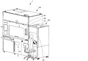
- FIG. 2 is a perspective view showing an external configuration of the co-infusion apparatus according to the embodiment of the present invention.
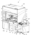
- FIG. 3 is a perspective view of the co-infusion apparatus according to the embodiment of the present invention with the main door opened.
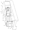
- FIG. 4 is a front view of the co-infusion apparatus according to the embodiment of the present invention with a main door and a part of the front wall removed.
- FIG. 5 is a perspective view showing a tray used in the co-infusion apparatus according to the embodiment of the present invention.
- FIG. 6 is a perspective view of the co-infusion apparatus according to the embodiment of the present invention as viewed from below.
- FIG. 1 is a block diagram showing a system configuration of a co-infusion apparatus according to an embodiment of the present invention.
- FIG. 2 is a perspective view showing an external configuration of the co-infusion apparatus according to the embodiment of the present invention
- FIG. 7 is a perspective view showing a holding portion of the first robot arm of the co-infusion apparatus according to the embodiment of the present invention.
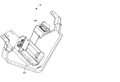
- FIG. 8 is a perspective view showing a holding portion of the second robot arm of the co-infusion apparatus according to the embodiment of the present invention.
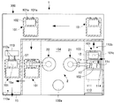
- FIG. 9 is a schematic plan view showing a tray transport portion of the co-infusion apparatus according to the embodiment of the present invention.
- FIG. 10 is a perspective view showing the mechanism of the tray transport unit of the co-infusion apparatus according to the embodiment of the present invention.
- FIG. 11 is a perspective view showing an ampoule cutter of the co-infusion apparatus according to the embodiment of the present invention.
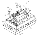
- FIG. 12 is a perspective view showing the internal configuration of the stirring device of the co-infusion apparatus according to the embodiment of the present invention.
- FIG. 13 is a perspective view showing a medicine reading unit of the co-infusion apparatus according to the embodiment of the present invention.
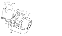
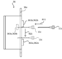
- FIG. 14 is a perspective view showing a needle bending detection unit of the co-infusion apparatus according to the embodiment of the present invention.
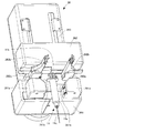
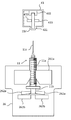
- FIG. 15 is a perspective view showing an internal structure of the injection needle attaching / detaching device of the mixed injection device according to the embodiment of the present invention.
- FIG. 16 is a perspective view showing an internal structure of the injection needle attaching / detaching device of the mixed injection device according to the embodiment of the present invention.
- FIG. 17 is a diagram illustrating an example of a captured image of the needle insertion confirmation camera of the co-infusion apparatus according to the embodiment of the present invention.
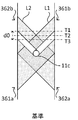
- FIG. 18A is a diagram illustrating details of a needle bending detection unit of the co-infusion apparatus according to the embodiment of the present invention.
- FIG. 18B is a diagram illustrating details of the needle bending detection unit of the co-infusion apparatus according to the embodiment of the present invention.
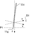
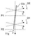
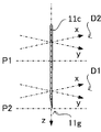
- FIG. 19A is a diagram illustrating details of a needle bending detection unit of the co-infusion apparatus according to the embodiment of the present invention.
- FIG. 19B is a diagram illustrating details of the needle bending detection unit of the co-infusion apparatus according to the embodiment of the present invention.
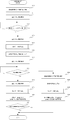
- FIG. 20 is a flowchart illustrating an example of an inclination correction process executed by the co-infusion apparatus according to the embodiment of the present invention.
- FIG. 20 is a flowchart illustrating an example of an inclination correction process executed by the co-infusion apparatus according to the embodiment of the present invention.
- FIG. 21A is a diagram illustrating an operation example of inclination correction processing of the co-infusion apparatus according to the embodiment of the present invention.
- FIG. 21B is a diagram illustrating an operation example of the inclination correction processing of the co-infusion apparatus according to the embodiment of the present invention.
- FIG. 21C is a diagram illustrating an operation example of the inclination correction processing of the co-infusion apparatus according to the embodiment of the present invention.
- FIG. 22 is a flowchart illustrating an example of a direction detection process executed by the co-infusion apparatus according to the embodiment of the present invention.
- FIG. 23 is a flowchart showing an example of the projection data acquisition process executed by the co-infusion apparatus according to the embodiment of the present invention.
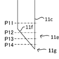
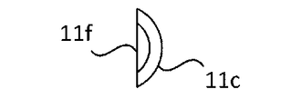
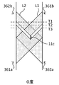
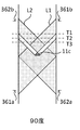
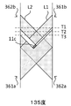
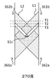
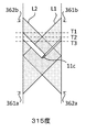
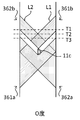
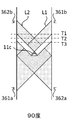
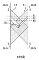
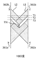
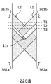
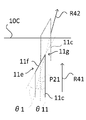
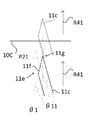
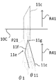
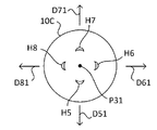
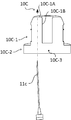
- FIG. 24A is a diagram showing a cross-section of the needle tip portion of the injection needle.
- FIG. 24B is a diagram illustrating a cross-section of the needle tip portion of the injection needle.
- FIG. 24C is a diagram illustrating a cross-section of the needle tip portion of the injection needle.
- FIG. 24D is a diagram illustrating a cross-section of the needle tip portion of the injection needle.
- FIG. 24E is a diagram illustrating a cross-section of the needle tip portion of the injection needle.
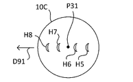
- FIG. 25A is a schematic diagram showing projection data acquired by the projection data acquisition process executed by the co-infusion apparatus according to the embodiment of the present invention.
- FIG. 25A is a schematic diagram showing projection data acquired by the projection data acquisition process executed by the co-infusion apparatus according to the embodiment of the present invention.
- FIG. 25B is a schematic diagram showing projection data acquired by the projection data acquisition process executed by the co-infusion apparatus according to the embodiment of the present invention.
- FIG. 25C is a schematic diagram showing projection data acquired by the projection data acquisition process executed by the co-infusion apparatus according to the embodiment of the present invention.
- FIG. 25D is a schematic diagram showing projection data acquired by the projection data acquisition process executed by the co-infusion apparatus according to the embodiment of the present invention.
- FIG. 25E is a schematic diagram showing projection data acquired by the projection data acquisition process executed by the co-infusion apparatus according to the embodiment of the present invention.
- FIG. 25F is a schematic diagram showing projection data acquired by the projection data acquisition process executed by the co-infusion apparatus according to the embodiment of the present invention.
- FIG. 25C is a schematic diagram showing projection data acquired by the projection data acquisition process executed by the co-infusion apparatus according to the embodiment of the present invention.
- FIG. 25D is a schematic diagram showing projection data acquired by the projection data acquisition process executed by the co-infusion
- FIG. 25G is a schematic diagram showing projection data acquired by the projection data acquisition process executed by the co-infusion apparatus according to the embodiment of the present invention.
- FIG. 25H is a schematic diagram showing projection data acquired by the projection data acquisition process executed by the co-infusion apparatus according to the embodiment of the present invention.
- FIG. 25I is a schematic diagram showing projection data acquired by the projection data acquisition process executed by the co-infusion apparatus according to the embodiment of the present invention.
- FIG. 26 is a diagram illustrating an example of orientation correspondence information used in the co-infusion apparatus according to the embodiment of the present invention.
- FIG. 27A is a schematic diagram showing projection data acquired by the projection data acquisition process executed by the co-infusion apparatus according to the embodiment of the present invention.
- FIG. 27B is a schematic diagram showing projection data acquired by the projection data acquisition process executed by the co-infusion apparatus according to the embodiment of the present invention.
- FIG. 27C is a schematic diagram showing projection data acquired by the projection data acquisition process executed by the co-infusion apparatus according to the embodiment of the present invention.
- FIG. 27D is a schematic diagram showing projection data acquired by the projection data acquisition process executed by the co-infusion apparatus according to the embodiment of the present invention.
- FIG. 27E is a schematic diagram showing projection data acquired by the projection data acquisition process executed by the co-infusion apparatus according to the embodiment of the present invention.
- FIG. 27F is a schematic diagram showing projection data acquired by the projection data acquisition process executed by the co-infusion apparatus according to the embodiment of the present invention.
- FIG. 27C is a schematic diagram showing projection data acquired by the projection data acquisition process executed by the co-infusion apparatus according to the embodiment of the present invention.
- FIG. 27D is a schematic diagram showing projection data acquired by the projection data acquisition process executed by the co-infusion
- FIG. 27G is a schematic diagram showing projection data acquired by the projection data acquisition process executed by the co-infusion apparatus according to the embodiment of the present invention.
- FIG. 27H is a schematic diagram showing projection data acquired by the projection data acquisition process executed by the co-infusion apparatus according to the embodiment of the present invention.
- FIG. 27I is a schematic diagram showing projection data acquired by the projection data acquisition process executed by the co-infusion apparatus according to the embodiment of the present invention.
- FIG. 28 is a diagram showing an example of orientation correspondence information used in the co-infusion apparatus according to the embodiment of the present invention.
- FIG. 29A is a diagram for explaining a cap mounting process executed by the co-infusion apparatus according to the embodiment of the present invention.
- FIG. 29A is a diagram for explaining a cap mounting process executed by the co-infusion apparatus according to the embodiment of the present invention.
- FIG. 29B is a diagram for explaining a cap mounting process executed by the co-infusion apparatus according to the embodiment of the present invention.
- FIG. 30A is a view for explaining a cap mounting process executed by the co-infusion apparatus according to the embodiment of the present invention.
- FIG. 30B is a diagram for explaining a cap mounting process executed by the co-infusion apparatus according to the embodiment of the present invention.
- FIG. 30C is a view for explaining a cap mounting process executed by the co-infusion apparatus according to the embodiment of the present invention.
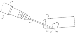
- FIG. 31A is a view for explaining a first puncture process executed by the co-infusion apparatus according to the embodiment of the present invention.
- FIG. 31B is a diagram for describing a first puncture process executed by the co-infusion apparatus according to the embodiment of the present invention.
- FIG. 31C is a view for explaining a first puncture process executed by the co-infusion apparatus according to the embodiment of the present invention.
- FIG. 32A is a view for explaining a second puncture process executed by the co-infusion apparatus according to the embodiment of the present invention.
- FIG. 32B is a diagram for describing a second puncture process executed by the co-infusion apparatus according to the embodiment of the present invention.
- FIG. 33A is a view for explaining a third puncture process executed by the co-infusion apparatus according to the embodiment of the present invention.
- FIG. 33B is a view for explaining a third puncture process executed by the co-infusion apparatus according to the embodiment of the present invention.
- FIG. 34A is a view for explaining a third puncture process executed by the co-infusion apparatus according to the embodiment of the present invention.
- FIG. 34B is a view for explaining a third puncture process executed by the co-infusion apparatus according to the embodiment of the present invention.
- FIG. 35A is a view for explaining a third puncture process executed by the co-infusion apparatus according to the embodiment of the present invention.
- FIG. 35B is a view for explaining a third puncture process executed by the co-infusion apparatus according to the embodiment of the present invention.
- FIG. 36A is a view for explaining a chemical liquid suction process executed by the co-infusion apparatus according to the embodiment of the present invention.
- FIG. 36B is a view for explaining a chemical liquid suction process executed by the co-infusion apparatus according to the embodiment of the present invention.
- FIG. 37A is a diagram for explaining the orientation detection process executed by the co-infusion apparatus according to another embodiment of the present invention.
- FIG. 37B is a diagram for explaining the orientation detection process executed by the co-infusion apparatus according to another embodiment of the present invention.
- FIG. 37C is a diagram for describing orientation detection processing executed by the co-infusion apparatus according to another embodiment of the present invention.
- FIG. 38A is a diagram for describing a direction detection process executed by the co-infusion apparatus according to another embodiment of the present invention.
- FIG. 38B is a diagram for explaining the orientation detection process executed by the co-infusion apparatus according to another embodiment of the present invention.
- FIG. 38C is a diagram for describing orientation detection processing executed by the co-infusion apparatus according to another embodiment of the present invention.
- FIG. 39A is a view for explaining a fourth puncture process executed by the co-infusion apparatus according to the embodiment of the present invention.
- FIG. 39B is a view for explaining a fourth puncture process executed by the co-infusion apparatus according to the embodiment of the present invention.
- FIG. 40 is a diagram showing an example of a required time table used in the co-infusion apparatus according to the embodiment of the present invention.
- the co-infusion apparatus 1 includes a co-infusion control apparatus 100, a medicine loading unit 200, and a co-infusion processing unit 300.
- the co-infusion control unit 100 controls the operation of the co-infusion processing unit 300, so that a predetermined amount of the anti-cancer drug or the like indicated in the preparation data is delivered by the syringe.
- a mixed injection process is performed in which one or a plurality of ampoules or vials in which the liquid is stored is injected into another container such as an infusion container.
- the mixed injection process include a process of sucking a drug from a container such as an ampoule or a vial with a syringe and injecting the drug into a container such as another ampoule or a vial, or a container such as an infusion container using a syringe.
- a process of sucking a medicine and injecting it into a container such as another vial is also included. That is, sanitary saline or glucose contained in the infusion bag is an example of the drug to be subjected to the mixed injection process.
- the mixed injection control device 100 includes a first control unit 400 and a second control unit 500 that are communicably connected.
- the first control unit 400 is provided on the medicine loading unit 200 side
- the second control unit 500 is provided on the mixed injection processing unit 300 side.
- each processing procedure of the mixed injection processing is the first control unit 400 and the second control. Any one of the units 500 may be executed.
- the mixed injection control device 100 may include one control unit or three or more control units as another embodiment.
- part or all of the processing executed by the first control unit 400 and the second control unit 500 may be executed by an electronic circuit such as an ASIC or DSP.
- the first control unit 400 can communicate with a host system 600 such as an electronic medical record system or a dispensing management system that inputs preparation data to the co-infusion apparatus 1.
- the preparation data is data for preparation generated based on prescription data or the prescription data itself.
- the prescription data includes prescription delivery date, patient ID, patient name, patient birth date, drug information (drug code, drug name, dose, etc.), dosage form information (internal use, external use, etc.), usage information (After three meals a day, etc.), medical treatment type (outpatient, hospitalization, etc.), medical department, ward, hospital room, etc. are included.
- the preparation data includes patient information, doctor information, drug information, drug prescription amount, drug container type (ampoules with drug solution, vials with drug solutions, vials with powder drugs, etc.), preparation content information (mixed injection process) ), Preparation procedure information (work contents, dissolved drug, solvent, dissolved drug amount, solvent amount, sampling amount), preparation date, prescription category, dosing date, Includes department, ward, preparation time, etc.
- the first control unit 400 is a personal computer including a CPU 401, a ROM 402, a RAM 403, a data storage unit 404, an operation unit 405, and the like.
- Various electrical components such as a display 203, a barcode reader 204, and an air cleaning device 205, which will be described later, provided in the medicine loading unit 200 are connected to the first control unit 400.
- the CPU 401 is a processor that executes processing according to various control programs.
- the ROM 402 is a non-volatile memory in which programs such as BIOS executed by the CPU 401 are stored in advance.
- the RAM 403 is a volatile memory or a non-volatile memory used for development of various control programs and temporary storage of data by the CPU 401.
- the data storage unit 404 is a hard disk or the like that stores various application programs executed by the CPU 401 and various data. Specifically, the preparation data input from the host system 600 is stored in the data storage unit 404.
- the first control unit 400 stores the identification information of the later-described tray 101 corresponding to each preparation data together with the preparation data input from the host system 600. For example, the first control unit 400 associates the preparation data with the tray 101. It is also conceivable that information indicating the correspondence between the preparation data and the tray 101 is input to the co-infusion apparatus 1 together with the preparation data.
- the data storage unit 404 stores various databases such as an injection needle master, a medicine master, a patient master, a doctor master, a prescription category master, a clinical department master, and a ward master.
- the injection needle master the shape of the tip of the injection needle is stored for each type of injection needle.
- the shape of the needle tip of the injection needle includes the outer diameter of the needle tube of the injection needle, the angle of the tip, the length of the cut surface (inclined surface), and the like.
- the medicine master includes a medicine code, a medicine name, a JAN code (or RSS), a medicine bottle code, a classification (dosage form: powder, tablet, liquid medicine, topical medicine, etc.), specific gravity, kind of medicine (ordinary medicine, Anticancer drugs, poisons, narcotics, powerful drugs, antipsychotics, therapeutic drugs, etc.), formulation changes, excipients, precautions, types of drug containers (ampoules, vials), drug capacity per drug container ( Information) such as the predetermined amount) and the weight of the drug container.
- the data storage unit 404 stores in advance a mixed injection control program for causing the CPU 401 to execute various processes.
- the mixed injection control program may be read from a recording medium such as a CD, a DVD, a BD, or a flash memory and installed in the data storage unit 404 by a reading device (not shown) included in the first control unit 400. Good.
- the operation unit 405 includes various operation means such as a keyboard, a mouse, or a touch panel that receives various user operations in the first control unit 400.
- the second control unit 500 is a personal computer including a CPU 501, a ROM 502, a RAM 503, a data storage unit 504, an operation unit 505, and the like.
- the second control unit 500 includes a first robot arm 21, a second robot arm 22, a tray transport unit 110, a touch panel monitor 14, an IC reader 101c, an IC reader 15a, a tray, which will be described later, provided in the mixed injection processing unit 300.
- Various electrical components such as a confirmation camera 41 and a syringe confirmation camera 42 are connected.
- the CPU 501 is a processor that executes processing according to various control programs.
- the ROM 502 is a non-volatile memory in which programs such as BIOS executed by the CPU 501 are stored in advance.
- the RAM 503 is a volatile memory or a non-volatile memory used for development of various control programs by the CPU 501 and temporary storage of data.
- the data storage unit 504 is a hard disk or the like that stores various application programs executed by the CPU 501 and various data. Specifically, the data storage unit 504 stores in advance a mixed injection control program for causing the CPU 501 to execute a mixed injection process described later.
- the mixed injection control program may be read from a recording medium such as a CD, a DVD, a BD, or a flash memory and installed in the data storage unit 504 by a reading device (not shown) included in the second control unit 500. Good.
- the present invention can also be understood as an invention of the mixed injection control program for causing the CPU 401 and the CPU 501 to execute various processes in the mixed injection control device 100 or a computer-readable recording medium on which the mixed injection control program is recorded. Good. Further, the present invention may be understood as an invention of a co-infusion method for executing each procedure of the co-infusion process in the co-infusion apparatus 1.
- the operation unit 505 includes various operation means such as a keyboard, a mouse, or a touch panel for receiving various user operations in the second control unit 500.
- the medicine loading unit 200 is a clean bench including a door 201, a work table 202, a display 203, a barcode reader 204, and an air cleaning device 205. As shown in FIG. 3, the medicine loading unit 200 and the mixed injection processing unit 300 are communicated with each other through a tray insertion port 114 formed on a side surface of the mixed injection processing unit 300.
- the display 203 is a display means such as a liquid crystal display or an organic EL display that displays various types of information in response to a control instruction from the first control unit 400. Specifically, the display 203 displays preparation data and the like that are candidates for co-infusion in the co-infusion apparatus 1. Further, the barcode reader 204 reads a barcode described in a prescription or a preparation instruction, and inputs the content of the barcode to the first control unit 400. The air cleaning device 205 supplies air into the medicine loading unit 200 through a predetermined filter.
- the door 201 is provided on the front surface of the medicine loading unit 200 and can be opened and closed vertically. As shown in FIG. 2, the user performs a preparatory work for the mixed injection process executed by the mixed injection device 1 in a state where the door 201 is slightly opened and a hand is placed in the medicine loading unit 200.
- the tray 101 placed on the work table 202 includes a medicine container 10 (an example of a container) used in the mixed injection process performed by the mixed injection apparatus 1 and a syringe, as shown in FIG. 11 and an infusion bag 12 (an example of a container) are accommodated.
- the preparatory operation includes, for example, a loading operation in which the medicine container 10, the syringe 11, and the infusion bag 12 are placed at predetermined positions of the tray 101 and the tray 101 is loaded into the mixed injection processing unit 300. It is.
- the chemical container 10 is an ampule
- the chemical container 10 is referred to as an ampule 10A
- the chemical container 10 is referred to as a vial 10B.
- the tray 101 includes an electronic paper 101a on which a patient name and application are displayed as characters, and an IC tag 101b (recording medium) such as an RFID (Radio Frequency Identification) tag capable of reading and writing various types of information. Example). Identification information for identifying the tray 101 is stored in the IC tag 101b.
- the tray 101 holds an instrument mounting portion 102 (see FIG. 9) on which the drug container 10 and the syringe 11 (syringe 11a, injection needle 11c, cap 11d) are mounted, and the infusion bag 12. And an infusion bag holding part 103 (see FIG. 5).
- the instrument mounting part 102 and the infusion bag holding part 103 can be individually attached to and detached from the tray 101.
- the equipment mounting portion 102 is provided with a support portion 102A that supports the ampoule 10A in an inclined state.
- the ampoule 10A is set in a state where the ampoule 10A is stood diagonally by the support portion 102A. Thereby, a chemical
- the injection needle 11c of the syringe 11 and the like are set in an inclined state on the support portion 102A.
- the injection needle 11c includes an injection needle with a syringe filter.
- a piece when the neck of the ampoule 10A is folded is injected from the syringe 11 into the infusion bag 12, or the piece flows into the syringe 11.
- a syringe needle with a syringe filter is used.
- the syringe filter is a filter generally referred to as a coma filter, and has a function of preventing passage of foreign substances other than chemicals.
- a syringe filter manufactured by Nippon Pole is generally known.
- the vial bottle 10B and the syringe 11 are set in a state in which they are laid on the device mounting portion 102, as shown in FIGS. At this time, the syringe 11 is in a state where the syringe 11a and the injection needle 11c are separated.
- the arrangement form in the equipment mounting portion 102 described here is an exemplification, and the present invention is not limited to this.
- the infusion bag holding portion 103 is provided with a chuck portion 140 for fixing the mixed injection port (neck portion) of the infusion bag 12.
- the user sets the infusion bag 12 in the infusion bag holding portion 103 in a state where the infusion bag 12 is held by the chuck portion 140.
- the infusion bag holding portion 103 is provided with an engagement hole portion 103a used when the infusion bag holding portion 103 is raised and lowered.
- the tray 101 is supplied to the mixed injection processing unit 300 through the tray insertion port 114 after the medicine container 10, the syringe 11, and the infusion bag 12 are set by the user. It is also conceivable that the medicine loading unit 200 includes a loading mechanism such as a belt conveyor that automatically loads the tray 101 into the mixed injection processing unit 300.
- a main door 301, a syringe take-out door 302, a garbage storage room door 13, a touch panel monitor 14, a tray discharge port 15, and the like are provided on the front surface of the mixed injection processing unit 300. .
- the main door 301 is opened and closed to access the mixed injection processing chamber 104, for example, when cleaning the mixed injection processing chamber 104 provided in the mixed injection processing unit 300.
- the said co-infusion apparatus 1 besides the said infusion bag 12 with which the chemical
- the syringe outlet door 302 is opened and closed when the syringe 11 is taken out from the mixed injection processing chamber 104.
- the waste storage chamber door 13 is for removing the waste from the waste storage chamber 13a in which waste such as the chemical container 10 and the syringe 11 after being used in the mixed injection processing in the mixed injection processing chamber 104 is stored. Is opened and closed. In addition, the tray discharge port 15 is opened and closed to take out the tray 101 on which the infusion bag 12 is placed after the medicine is mixedly injected by the mixed injection processing in the mixed injection processing chamber 104.
- the touch panel monitor 14 is a display unit such as a liquid crystal display or an organic EL display that displays various types of information in response to a control instruction from the second control unit 500.
- the touch panel monitor 14 can display, for example, images or videos taken by various cameras described later.
- the mixed injection processing chamber 104 includes a first robot arm 21, a second robot arm 22, an ampoule cutter 31, a stirring device 32, a mounting shelf 33, a rotating mounting portion 33 ⁇ / b> A, A medicine reading unit 34, a weighing meter 35, a needle bending detection unit 36, a mixed injection communication port 37, a needle insertion confirmation transparent window 38, a dust cover 132a, and the like are provided. Further, as shown in FIG.
- a tray confirmation camera 41, a syringe confirmation camera 42, a syringe needle attachment / detachment device 43, a needle insertion confirmation camera 44, a sterilization lamp 45, and the like are provided on the ceiling side of the mixed injection processing chamber 104.
- the first robot arm 21 and the second robot arm 22 are drive units having a multi-joint structure, and are provided in a hanging manner with a base end fixed to the ceiling side of the mixed injection processing chamber 104.
- the joints of the first robot arm 21 and the second robot arm 22 are 5 to 8 axes, respectively.
- each work process in the co-infusion process is executed by the double-arm first robot arm 21 and the second robot arm 22.
- the second control unit 500 individually drives drive motors provided at the joints of the first robot arm 21 and the second robot arm 22, so that the first robot arm 21 and the second robot arm 21 are driven.
- the robot arm 22 is caused to execute each operation in the mixed injection process.
- the mixed injection processing unit 300 has, for example, a configuration including one robot arm, a configuration including three or more robot arms, or a configuration not using a robot arm as long as the mixed injection processing unit 300 can execute the mixed injection processing. It may be.
- the first robot arm 21 includes a holding portion 25 that can hold devices such as the medicine container 10 and the syringe 11, and the holding portion 25 has a predetermined movable range. It is possible to move to an arbitrary position.
- the second robot arm 22 can hold and move equipment such as the medicine container 10 and the syringe 11 to an arbitrary position, and performs operations of sucking and injecting medicine by the syringe 11. It is an example of a holding part provided with the holding part 26 which can be.
- the first robot arm 21 and the second robot arm 22 are examples of first drive means
- the holding unit 26 is an example of second drive means.
- the second robot arm 22 can move the medicine container 10 and the syringe 11 to any position within a predetermined movable range.
- the holding portion 25 of the first robot arm 21 includes a pair of gripping claws 25a, a motor 251, two screw shafts 252, 253 rotated by the motor 251, the screw shaft 252, Nut blocks 254 and 255 screwed to 253 are provided.
- the pair of gripping claws 25a are fixed to the nut blocks 254 and 255, respectively. Then, the nut blocks 254 and 255 are moved by the rotation of the screw shafts 252 and 253, and the pair of gripping claws 25a approach and separate from each other to hold and release the holding portion 25.
- the pair of gripping claws 25a is a gripping portion having a recess suitable for holding the vial 10B and a recess suitable for holding the ampoule 10A on the tip side.
- FIG. 7 shows a state in which both the ampoule 10A and the vial bottle 10B are held, but in reality, one ampoule 10A or the vial bottle 10B is held.
- the holding unit 25 can also hold the injection needle 11c or the syringe 11 with the cap 11d attached by the pair of gripping claws 25a.
- the second control unit 500 can measure the diameter of the syringe 11 according to the driving amount of the motor 251 when the syringe 11 is held by the pair of gripping claws 25a of the holding unit 25. Is possible. Accordingly, the second controller 500 can determine whether the syringe 11 is a syringe designated by the preparation content information of the preparation data.
- the holding part 26 of the second robot arm 22 includes a syringe holding part 261, a plunger holding part 262, and a moving part 263.
- the syringe holder 261 includes a pair of gripping claws 261 a that hold the syringe 11 a of the syringe 11.
- the pair of gripping claws 261a are gripping portions that hold and release the syringe 11a of the syringe 11 by being close to and away from each other by a mechanism similar to the drive mechanism used in the holding portion 25.
- inclined portions 261b that are inclined downward from the upper end surface of the gripping claws 261a toward the facing surface are formed on opposing surfaces facing each other.
- the plunger holding portion 262 includes a pair of gripping claws 262a that hold the flange portion of the plunger 11b of the syringe 11.
- the pair of gripping claws 262a are gripping portions that hold and release the flange portion of the plunger 11b of the syringe 11 by being close to and separated from each other by a mechanism similar to the driving mechanism used in the holding portion 25. is there.
- a gripping claw 262b is fixed to the upper surface of each gripping claw 262a.
- Each of the gripping claws 262b is a gripping part that approaches and separates the pair of gripping claws 262a by approaching and separating, and grips not only the syringe 11 but also other devices such as the drug container 10.
- the recessed part for the collar part of the said plunger 11b to enter is formed in the upper surface of the opposing side of said pair of holding claw 262a.
- the tips of the pair of gripping claws 262b project forward from the pair of gripping claws 262a, and the pair of gripping claws 262b can easily grip equipment such as the ampoule 10A and the vial bottle 10B.
- the grip claw 262b may be provided on the grip claw 261a.
- the moving unit 263 can move the plunger holding unit 262 in the moving direction of the plunger 11b of the syringe 11.
- the moving unit 263 moves the plunger 11b by a driving mechanism such as a motor, a screw shaft rotated by the motor, a nut block screwed to the screw shaft, and a guide.
- the plunger holding part 262 is fixed to the nut block, and moves by the movement of the nut block.
- the mixed injection processing section 300 is provided with a tray transport section 110 that transports the tray 101 supplied from the tray insertion port 114 at the right end in FIG. 6 to the tray transport end section 110a at the left end. ing.
- FIG. 9 is a schematic plan view showing an example of the transport path of the tray 101 in the tray transport section 110.
- the inside of the tray transfer unit 110 is set at a positive pressure as compared with the inside of the mixed injection processing chamber 104.
- the tray transport unit 110 allows the tray 101 to pass through the rear side of the dust storage chamber 13 a located below the mixed injection processing chamber 104 and below the dust cover 132 a. It is provided to convey. Thereby, the said garbage storage chamber 13a can be accessed from the front side of the said co-infusion apparatus 1.
- the tray 101 that moves in the tray conveyance unit 110 is indicated by a two-dot chain line, and a plurality of the trays are simultaneously included in the tray conveyance unit 110. 101 does not exist.
- the tray transport unit 110 is provided with an IC reader 101c and an IC reader 15a capable of reading information from the IC tag 101b provided in the infusion bag holding unit 10 of the tray 101.
- the IC reader 101c and the IC reader 15a are RFID readers that read information from RFID tags.
- the IC reader 101c is provided in the tray conveyance start section 110b in which the tray 101 is loaded from the tray insertion port 114, and the IC reader 15a is configured to discharge the tray 101 from the tray discharge port 15. It is provided in the tray conveyance end portion 110a.
- the second control unit 500 determines that the tray 101 is inserted into the tray conveyance start unit 110b from the tray insertion port 114 based on a sensor output (not shown)
- the IC reader 101c performs the IC operation. Information is read from the tag 101b. Further, when the second control unit 500 determines that the tray 101 is inserted into the tray conveyance termination unit 110a based on a sensor output (not shown), the information is read from the IC tag 101b by the IC reader 15a. . Then, the second control unit 500 executes a tray collation process for determining whether or not the tray 101 is appropriate according to the reading results of the IC reader 101c and the IC reader 15a.
- the tray transport is performed.
- the shutter 111 that communicates and shields the unit 110 and the mixed injection processing chamber 104 is slid in the horizontal direction.
- the equipment placement unit 102 is exposed in the mixed injection processing chamber 104.
- FIG. 9 shows a state in which the equipment placing portion 102 is exposed in the mixed injection processing chamber 104.
- the tray transport unit 110 is configured to raise and lower the equipment placement unit 102 in the tray 101 moved into the tray transport unit 110 through the tray insertion port 114.
- An elevating part 112 is provided.
- the tray lifting / lowering unit 112 lifts the equipment placing unit 102 from the bottom to the top by driving the four shafts 112a provided in a vertically movable manner, for example.
- the second control unit 500 raises the equipment placing unit 102 by the tray lifting / lowering unit 112, and then performs imaging by the tray confirmation camera 41.
- the tray confirmation camera 41 photographs from above the medicine container 10 and the syringe 11 that are placed on the device placement section 102 that is determined in advance.
- the second control unit 500 executes an image recognition process using an image captured by the tray confirmation camera 41, and the number of the medicine containers 10 and the syringes 11 (the syringe 11a and the injection needle) indicated by the preparation data. 11c) or the like is present on the equipment placement unit 102.
- a bag lifting / lowering unit 113 that lifts and lowers the infusion bag holding unit 103 is provided in the tray transfer terminal end portion 110 a located in the left space of the mixed injection processing chamber 104.
- the second control unit 500 After the second control unit 500 transports the tray 101 to the front of the bag lifting / lowering unit 113, the second control unit 500 hooks the hook portion 113a of the bag lifting / lowering unit 113 into the engagement hole 103a from below. Then, the second control unit 500 drives the arc gear portion 113b formed with the hook portion 113a to rotate by a motor 113c, thereby raising the infusion bag holding portion 103 and opening the mixed injection port of the infusion bag 12. It is located in the mixed injection communication port 37. In addition, the second control unit 500 controls the motor 113c to drive the bag elevating unit 113 to incline the infusion bag holding unit 103 so that the mixed injection port of the infusion bag 12 faces upward or downward. can do.
- a dome-shaped light 120 and an infusion camera 121 for illuminating the infusion bag 12 conveyed to the tray conveyance end portion 110a are provided above the tray conveyance end portion 110a.
- the infusion camera 121 is provided in the center of the dome-shaped light 120 and reads a barcode attached to the surface of the infusion bag 12. Accordingly, the second control unit 500 can determine whether the infusion bag 12 is appropriate according to the barcode information read by the infusion camera 121.
- the ampoule cutter 31 As shown in FIG. 11, the ampoule cutter 31 is provided with a file part 31a, a waste tray 31b, a head insertion part 31c, a drive box 31f, a waste box 31g, and a grip part 31h.
- the file portion 31a is a member for notching the neck of the ampoule 10A, and the waste generated by the notch processing in the file portion 31a falls on the waste tray 31b.
- the first robot arm 21 holds the ampoule 10A and slides with the neck of the ampoule 10A in contact with the file portion 31a, so that the neck of the ampoule 10A is reached. Notched.
- the head insertion part 31c is positioned on the side of the head of the ampoule 10A protruding upward from the hole 31d and the hole 31d into which the head of the ampoule 10A to which the notch processing has been applied is inserted from below.
- a pusher 31e On the other hand, the drive box 31f has a cam provided therein and a drive motor for driving the cam. When the cam is driven by the drive motor, the pusher 31e is moved by the cam to the ampoule 10A. It reciprocates in the direction of approaching and separating from the head.
- the first robot arm 21 holds the ampoule 10A by the gripping claws 25a, the head of the ampoule 10A is inserted into the hole 31d from below, and the head above the neck is moved upward. To protrude. Thereafter, when the drive motor of the drive box 31f is driven by the second controller 500 and the pusher 31e is moved in the direction of pushing the head of the ampoule 10A, the pusher 31e pushes the head. To be folded. At this time, the head folded by the pusher 31e falls into the waste box 31g.
- the grip portion 31h is used by a user when the ampule cutter 31 is slid along a rail 31i (see FIG. 4) that slidably supports the ampule cutter 31.
- the agitator 32 when a medicine that needs to be dissolved such as powder (powder) is contained in the vial 10B, injects an infusion or medicine into the vial 10B to dissolve the medicine, Used when producing mixed chemicals.
- the stirring device 32 includes a roller 32a, a pressing portion 32b, a rotation support portion 32c, a support base 32d, a horizontal swing mechanism 32e, a support portion 32f, a drive motor 32g, and the like. Is provided.
- the two rollers 32a are opposed to each other with a predetermined distance therebetween.
- One roller 32a is rotatably supported, and the other roller 32a is connected to the drive motor 32g.
- Each of the rollers 32a is elongated in the axial direction, and the stirring device 32 can simultaneously stir the two vial bottles 10B placed on both ends of the roller 32a in the axial direction. .
- the pressing portion 32b is a driven roller that is used to press the vial 10B placed on the roller 32a from above and rotates as the chemical container 10 rotates.
- the rotation support portion 32c rotates the pressing portion 32b in a direction in contact with or away from the drug container 10 by a drive motor (not shown).
- the support base 32d supports the roller 32a, the pressing portion 32b, the rotation support portion 32c, and the like.
- the horizontal swing mechanism 32e has, for example, a crank mechanism, and can swing the support base 32d in the axial direction of the roller 32a.
- the support portion 32f has U-shaped notches into which the neck of the vial bottle 10B is fitted at both ends in the axial direction of the roller 32a.
- the vial 10B is placed on the roller 32a, the neck of the drug container 10 is engaged with the notch.
- the support base 32d is swung in the axial direction of the roller 32a by the horizontal swing mechanism 32e, the chemical container 10 swings following the swing of the roller 32a in the axial direction.
- the medicine in the medicine container 10 is stirred in the horizontal direction.
- the placement shelf 33 is used to temporarily place the medicine container 10, the syringe 11, and the like in the mixed injection process executed in the mixed injection device 1.
- the placement shelf 33 is provided at a position accessible by both the first robot arm 21 and the second robot arm 22.
- the vial bottle 10B is placed in a state where it is stood at a predetermined position.
- the placement shelf 33 is provided with an inclination holding part for holding the ampoule 10A in an inclined state, and the ampoule 10A is placed in an inclined state on the inclination holding part.
- the mounting shelf 33 is formed with a neck holding hole having a predetermined diameter, into which the neck of the syringe 11 is fitted, and the syringe 11 is in a state of only a syringe without an injection needle 11c attached. And temporarily placed with the neck facing down.
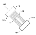
- the rotation mounting portion 33A is used for the operation for rotating the syringe 11 in the circumferential direction, and is provided at a position where the first robot arm 21 can be accessed.
- the rotation mounting portion 33A is formed with a neck holding hole having a predetermined diameter in which the neck portion of the syringe 11 is fitted, similarly to the mounting shelf 33, and the syringe 11 is a syringe needle. It is placed with the neck portion facing downward in the state of only the syringe not attached with 11c.
- the first robot arm 21 can rotate the syringe 11 by 180 degrees in the circumferential direction after placing the syringe 11 on the rotation placement portion 33A.
- the first robot arm 21 gradually rotates the syringe 11 up to 180 degrees in the circumferential direction by repeatedly executing the following (a) and (b).
- the medicine reading unit 34 reads a barcode indicating medicine information of the contained medicine described on a label attached to the medicine container 10 such as the ampoule 10A and the vial bottle 10B.
- the medicine reading unit 34 includes two rollers 34a and a barcode reader 34b as shown in FIG.
- the rollers 34a are arranged to face each other with a predetermined interval.
- One of the rollers 34a is rotatably supported, and the other roller 34a is connected to a drive motor (not shown).
- the two rollers 34a are driven by the drive motor to rotate the medicine container 10 placed between the rollers 34a in the circumferential direction.
- medical agent container 10 can be rotated once in the circumferential direction, the whole region of the label affixed on the said chemical
- the barcode reader 34b reads the barcode from the label of the chemical container 10 rotated by the roller 34a.
- the weighing instrument 35 is used to measure the weight of the syringe 11 in the mixed injection process executed in the mixed injection device 1, and the measurement result by the weighing instrument 35 is input to the second control unit 500.
- the weigh scale 35 is disposed within the movable range of the second robot arm 22 and measures the weight of the syringe 11 placed by the second robot arm 22.
- the needle bending detection unit 36 is formed with a long hole 36a into which the injection needle 11c of the syringe 11 can be inserted and moved.
- the needle bending detection unit 36 irradiates and receives detection light across the elongated hole 36a, and the first optical sensor 361 and the second optical sensor 362 are arranged so that the detection lights are not parallel to each other. Is provided. That is, the detection light irradiation directions of the first optical sensor 361 and the second optical sensor 362 are different. Detection results from the first optical sensor 361 and the second optical sensor 362 are input to the second controller 500.
- the injection needle 11c attached to the syringe 11 is inserted into the elongated hole 36a and moved up and down.
- the detection light of each of the first optical sensor 361 and the second optical sensor 362 is blocked by the injection needle 11c, the first optical sensor 361 and the second optical sensor 362 are turned off.
- the second control unit 500 can detect the bending of the injection needle 11c using the position information of the injection needle 11c when the detection light is blocked.
- the injection needle 11c is photographed with a camera and needle bending or the like is detected by image recognition on the photographed image. Then, when the injection needle 11c is bent, the second control unit 500, for example, based on the bending amount of the injection needle 11c, the infusion bag 12 with the injection needle 11c by the second robot arm 22, for example. It is possible to adjust the position of the needle tip at the time of puncturing the rubber stopper of the mixed injection port.
- the mixed injection communication port 37 is formed in a dome-shaped portion protruding outward on the side wall of the mixed injection processing chamber 104, and the dome-shaped portion of the infusion bag 12 extends vertically. A notch for passing the mixed injection port is formed. Therefore, when the infusion bag holding part 103 is raised, the mixed injection port of the infusion bag 12 is located in the mixed injection processing chamber 104.
- the needle insertion confirmation transparent window 38 is a window through which the infusion bag 12 of the tray transfer terminal portion 110a can be seen from the mixed injection processing unit 300, and the injection needle 11c of the syringe 11 is inserted into the infusion bag 12. Used when taking an image to check the status.
- the syringe confirmation camera 42 is disposed on the ceiling portion of the mixed injection processing unit 300.
- the syringe confirmation camera 42 is used to photograph the syringe 11 in order to confirm the presence and amount of the medicine sucked into the syringe 11.
- the syringe confirmation camera 42 may capture an image within a fixed imaging range, but can be arbitrarily changed in position and size of the imaging range by being controlled by the second control unit 500. It may be possible. Further, as will be described later, in the mixed injection device 1, the syringe 11 and the medicine container 10 are photographed at a time by the syringe confirmation camera 42, and a highly reliable inspection image is provided.
- the second control unit 500 uses the data storage unit 404, the data storage unit, and the data storage unit 404, the data storage unit, in order to check the appropriateness of the mixed injection processing executed by the mixed injection device 1, for example, with the image taken by the syringe confirmation camera 42. 504 or a storage unit such as a hard disk provided outside the mixed injection device 1. Then, the second control unit 500 causes the touch panel monitor 14 or a display device such as the display 203 to display an image captured by the syringe confirmation camera 42 during the inspection by the user.
- the injection needle attaching / detaching device 43 As shown in FIGS. 15 and 16, the injection needle attaching / detaching device 43 is inserted with the tip of the injection needle 11 c having the cap 11 d fitted upward into the hole 43 b of the chuck portion 43 a in which the cut portion is formed.
- the motor 43c When the motor 43c is driven, the hole 43b of the chuck portion 43a is expanded by a cam mechanism (not shown), and the injection needle 11c can be inserted together with the cap 11d.
- the driving of the motor 43c is stopped, the holding state of the cap 11d and the injection needle 11c is maintained by the spring 43d.
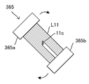
- the needle turning motor 43e When the needle turning motor 43e is driven, the gear 43f and the gear 43g are rotated, the chuck portion 43a is rotated, and the cap 11d and the injection needle 11c are rotated.
- Each of the injection needle 11c and the cap 11d is provided with a rib that comes into contact with the cap 11d when the cap 11d rotates in the circumferential direction with the injection needle 11c attached. Therefore, the injection needle 11c rotates with the cap 11d when the cap 11d of the injection needle 11c is rotated by the chuck portion 43a, and is attached to and detached from the syringe 11a.
- the syringe needle 11 is moved closer to or away from the chuck portion 43a by the second robot arm 22 while the cap 11d is held by the chuck portion 43a. It is also possible to automatically attach and detach the cap 11d to and from 11c.
- the tip of the injection needle 11c faces upward, the tip opening of the syringe 11a from which the injection needle 11c is removed faces upward, and dripping from the neck opening of the syringe 11a. Can be prevented.
- the needle insertion confirmation camera 44 photographs the infusion bag 12 located outside the mixed injection processing chamber 104 and the syringe 11 in the mixed injection processing chamber 104 so as to fit in one image.
- the second controller 500 photographs the direction of the needle insertion confirmation transparent window 38 with the needle insertion confirmation camera 44 when the rubber stopper of the mixed injection port of the infusion bag 12 is punctured with the injection needle 11c.
- an image captured by the needle insertion confirmation camera 44 is displayed on the touch panel monitor 14, for example.
- FIG. 17 is an example of an image taken by the needle insertion confirmation camera 44. Thereby, the user can confirm whether or not the distal end side of the injection needle 11c is located in the infusion bag 12 by the captured image.
- the photographed image is stored in a storage unit such as a hard disk provided inside or outside the mixed injection device 1 for final inspection, for example.
- a storage unit such as a hard disk provided inside or outside the mixed injection device 1 for final inspection, for example.
- the germicidal lamp 45 is turned on, for example, 3 hours before the start of the mixed injection process. As shown in FIG. 6, one of the two germicidal lamps 45 is provided at a position between the first robot arm 21 and the second robot arm 22. Therefore, the amount of sterilization light blocked by the first robot arm 21 and the second robot arm 22 is reduced, and the inside of the mixed injection processing chamber 14 can be sterilized uniformly. Further, the mixed injection processing unit 300 sucks air in the mixed injection processing chamber 104 from a slit 104b (see FIGS. 3 and 4) formed in a lower portion of the side wall of the mixed injection processing chamber 104, and the mixed injection processing chamber 300.
- a slit 104b see FIGS. 3 and 4
- An exhaust system for exhausting air from an exhaust fan (not shown) provided above 104 is provided.
- an air supply system is also provided that cleans the outside air from an air inlet formed in the ceiling portion of the mixed injection processing chamber 104 and guides it to the mixed injection processing chamber 104 and the like.
- the second control unit 500 controls the first robot arm 21 and the second robot arm 22 and the like, based on the preparation data.
- the medicine is sucked from the medicine container 10 with the syringe 11 and the medicine is injected from the syringe 11 into another medicine container such as the infusion bag 12.
- the second control unit 500 When the tray 101 is supplied to the tray transport unit 110, the second control unit 500 reads the identification information of the tray 101 from the IC tag 101b of the tray 101 by the IC reader 101c. Then, the second control unit 500 opens the shutter 111 when the identification information of the tray 101 matches the identification information previously associated with the preparation data of the mixed injection process. Thereafter, the second control unit 500 raises the equipment placement unit 102 of the tray 101 by the tray lifting / lowering unit 112 of the tray transport unit 110 and exposes it to the mixed injection processing chamber 104.
- the second control unit 500 photographs the equipment placing unit 102 with the tray confirmation camera 41. Then, the second control unit 500 performs the position and orientation of the equipment such as the ampule 10A and the syringe 11 placed on the equipment placement section 102 by image recognition processing based on the image captured by the tray confirmation camera 41. To figure out. In particular, every time the ampule 10A or the syringe 11 is taken out from the device mounting unit 102, the second control unit 500 captures the device mounting unit 102 with the tray confirmation camera 41, and the latest from the captured image. The position and direction of the ampule 10A and the syringe 11 are grasped.
- the second controller 500 uses the first robot arm 21 to place the syringe 11 placed on the equipment placement unit 102 exposed in the mixed injection processing chamber 104 on the placement shelf 33. Temporary placement. Further, the second control unit 500 sets the ampoule 10 ⁇ / b> A placed on the equipment placing unit 102 to the medicine reading unit 34 by the first robot arm 21. Then, the second control unit 500 reads information such as the type of medicine stored in the ampoule 10 ⁇ / b> A by the medicine reading unit 34.
- the second control unit 500 sets the first injection needle 11c to the injection needle attaching / detaching device 43 and the second injection needle 11c to the placement shelf 33 by the first robot arm 21.
- the first injection needle 11c is an injection needle without a syringe filter
- the second injection needle 11c is an injection needle with a syringe filter.
- a cap 11 d is attached to the injection needle 11 c placed on the device placement section 102, and the cap 11 d is attached / detached by the injection needle attaching / detaching device 43.
- the injection needle 11c is set on the tray 101 in a state where it is mounted on the syringe 11a of the syringe 11. In this case, the step of setting the injection needle 11c in the syringe 11 is omitted.
- the tray placing unit 102 is lowered by the tray lifting / lowering unit 112 of the tray transporting unit 110, thereby the tray 101.
- the second control unit 500 confirms whether or not all the devices on the device mounting unit 102 have been taken out by an image recognition process based on a photographed image by the tray confirmation camera 41.
- the second control unit 500 closes the shutter 111 and causes the tray conveyance unit 110 to convey the tray 101 to the tray conveyance termination unit 110a.
- the second control unit 500 sets the mixed injection port of the infusion bag 12 held by the infusion bag holding unit 103 of the tray 101 by the bag elevating unit 113 of the tray transport unit 110 to the mixed injection processing chamber. It is located in the mixed injection communication port 37 formed in 104.
- the second control unit 500 moves the ampule 10A set in the medicine reading unit 34 to the mounting table 33 by the second robot arm 22.
- the second control unit 500 takes out the syringe 11 from the mounting table 33 by the first robot arm 21 and sets it on the second robot arm 22.
- the second controller 500 causes the second robot arm 22 to move the syringe 11 to the syringe needle attaching / detaching device 43 to set the syringe needle 11c in the syringe 11.
- the second controller 500 causes the second robot arm 22 to move the syringe 11 to the needle bend detector 36 to detect whether the injection needle 11c is bent.
- the injection needle 11c is set on the tray 101 while being mounted on the syringe 11. In this case, the step of setting the injection needle 11c in the syringe 11 is omitted.
- the second control unit 500 takes out the ampoule 10A from the mounting table 33 by the first robot arm 21 and folds the head of the ampoule 10A using the ampoule cutter 31. Then, the second control unit 500 causes the ampule 10A and the syringe 11 to approach each other by the first robot arm 21 and the second robot arm 22, and moves the injection needle 11c of the syringe 11 to the ampule 10A. Insert inside. Thereafter, the second control unit 500 operates the plunger 11b with the second robot arm 22 and sucks the amount of medicine predetermined by the preparation data from the ampoule 10A with the syringe 11.
- the first robot arm 21 and the second robot arm 22 gradually tilt the posture of the ampoule 10A and the syringe 11.
- the ampoule 10A is A state in which the medicine is moved to the side of the mouth (neck) by tilting about 10 degrees with respect to the direction is formed. This makes it possible to suck up the medicine without leaving as much as possible without putting the tip of the injection needle 11c of the syringe 11 on the bottom of the ampoule 10A.
- the second controller 500 controls one or both of the first robot arm 21 and the second robot arm 22 to suck the ampule 10A and the medicine after the medicine is sucked.
- the syringe 11 is moved within the imaging range of the syringe confirmation camera 42.
- the second control unit 500 captures the ampule 10A and the syringe 11 at a time using the syringe confirmation camera 42, and records the captured image in the data storage unit 504 as an inspection image.
- the syringe confirmation camera 42 captures the predetermined photographing range.
- the syringe control camera 42 so that the ampule 10A and the syringe 11 after the second controller 500 is moved by the first robot arm 21 and the second robot arm 22 can be photographed at a time. It is also conceivable that the shooting range can be changed.
- the second control unit 500 replaces the injection needle 11 c of the syringe 11 by the first robot arm 21 and the second robot arm 22.
- the second controller 500 uses the second robot arm 22 to move the syringe 11 to the needle bend detector 36 and detects whether the injection needle 11c is bent.
- the second robot arm 22 moves the syringe 11 to the injection needle attaching / detaching device 43 to attach the cap 11d to the injection needle 11c.
- the second control unit 500 rotates the cap 11 d by the injection needle attaching / detaching device 43 to remove the injection needle 11 c from the syringe 11.
- the removal of the injection needle 11c may be performed by rotating the cap 11d by the first robot arm 21 and the second robot arm 22.
- the second controller 500 opens the dust cover 132a, drops the injection needle 11c held by the injection needle attaching / detaching device 43 by the first robot arm 21 into the dust storage chamber 13a, and discards it. To do. Thereafter, the second control unit 500 causes the first robot arm 21 to set the injection needle 11c with the syringe filter on the injection needle attaching / detaching device 43 from the mounting table 33. Then, the second control unit 500 moves the syringe 11 to the injection needle attaching / detaching device 43 by the second robot arm 22 and attaches the injection needle 11 c to the syringe 11.
- the second control unit 500 moves the syringe 11 to the needle bending detection unit 36 by the second robot arm 22 and detects the presence or absence of the bending of the injection needle 11c.
- the injection needle 11c is replaced when the drug is sucked from the ampule 10A and when the infusion is injected into the infusion bag 12, and the fragments of the ampule 10A are replaced with the infusion bag. 12 is prevented.
- the second control unit 500 punctures the injection needle 11c of the syringe 11 into the rubber stopper of the mixed injection port of the infusion bag 12 conveyed to the tray conveyance termination unit 110a by the second robot arm 22. Then, the mixed medicine in the syringe 11 is injected into the infusion bag 12.
- the second control unit 500 opens the dust lid 132a and drops the ampoule 10A into the dust storage chamber 13a by the first robot arm 21 and discards it.
- the second controller 500 moves the syringe 11 to the injection needle attaching / detaching device 43 by the second robot arm 22 and attaches the cap 11d to the injection needle 11c of the syringe 11.
- the syringe 11 is dropped into the garbage storage chamber 13a and discarded.
- the second control unit 500 reads various images taken by the syringe confirmation camera 42 and the like from the data storage unit 504 and displays them on the touch panel monitor 14. As a result, the user can check whether or not the mixed injection process is appropriate while looking at the touch panel monitor 14.
- next preparation data (hereinafter referred to as “next adjustment data”) exists.
- the mixed injection process based on the next preparation data is executed.
- the second robot arm 22 is in a standby state until the operation of taking the equipment such as the syringe 11 and the injection needle 11c into the mixed injection processing chamber 104 is executed.
- the equipment placement unit 102 is located within the movable range of the first robot arm 21 and outside the movable range of the second robot arm 22. Yes. Therefore, only the first robot arm 21 can take in the equipment from the equipment placement portion 102 of the tray 101. In this case, the second robot arm 22 cannot perform the next operation until the equipment taking-in operation by the first robot arm 21 is completed. Then, it is conceivable that after the taking-in operation is completed, an assembly operation of the syringe 11 and the injection needle 11c using the injection needle attaching / detaching device 43 by the second robot arm 22 is started. However, in this case, the waiting time of the second robot arm 22 is wasted and the efficiency of the mixed injection process is reduced.
- the second control unit 500 in parallel with the discarding process performed using the second robot arm 22, It is conceivable to determine whether or not the discarding process has been completed while performing the loading operation using the first robot arm 21.
- the timing for determining whether or not the disposal process has ended is determined by the first robot arm 21, for example, when the equipment such as the medicine container 10 and the syringe 11 is replaced by the ampoule cutter 31, the stirring device 32, and the mounting table. 33, the end timing for each individual operation such as being placed on the rotation placement portion 33A, the medicine reading portion 34, or the like.
- the second control unit 500 determines that the disposal process has been completed, the second control unit 500 interrupts the loading operation, and uses the first robot arm 21 to move the syringe 11 (syringe 11a) to the second robot arm 22. Priority is given to the processing set to. Thereafter, the second controller 500 resumes the loading operation using the first robot arm 21.
- the second control unit 500 takes out the syringe 11 from the mounting table 33 and sets it on the second robot arm 22 when the syringe 11 is mounted on the mounting table 33.
- the second control unit 500 takes out the syringe 11 from the device mounting portion 102 and performs the first control. Set on the robot arm 21.
- the setting of the syringe 11 to the second robot arm 22 is performed with priority, for example, the assembly work of the syringe 11 and the injection needle 11c by the second robot arm 22 thereafter,
- the taking-in operation of the ampule 10A by the first robot arm 21 can be executed in parallel. Accordingly, the efficiency of the mixed injection process when the mixed injection process based on a plurality of the preparation data is continuously executed is increased, and the time required for the mixed injection process can be shortened. Even if the syringe 11 mounted on the device mounting portion 102 is the syringe 11a with the injection needle 11c attached thereto, the cap 11d is removed from the injection needle 11c of the syringe 11 etc. This operation can be performed in parallel with the operation of taking in the ampoule 10A by the first robot arm 21.
- the second control unit 500 When the tray 101 is supplied to the tray transport unit 110, the second control unit 500 reads the identification information of the tray 101 from the IC tag 101b of the tray 101 by the IC reader 101c. Then, the second control unit 500 opens the shutter 111 when the identification information of the tray 101 matches the identification information previously associated with the preparation data of the mixed injection process. Thereafter, the second control unit 500 raises the equipment placement unit 102 of the tray 101 by the tray lifting / lowering unit 112 of the tray transport unit 110 and exposes it to the mixed injection processing chamber 104.
- the second control unit 500 photographs the equipment placing unit 102 with the tray confirmation camera 41. Then, the second controller 500 determines the position of the equipment such as the vial 10B and the syringe 11 placed on the equipment placing section 102 by the image recognition process based on the image taken by the tray confirmation camera 41. Know the direction. In particular, each time the second control unit 500 takes out the vial 10B or the syringe 11 from the instrument mounting unit 102, the second control unit 500 captures the instrument mounting unit 102 with the tray confirmation camera 41, and from the captured image. The latest position and orientation of the vial 10B and the syringe 11 are grasped.
- the second controller 500 uses the first robot arm 21 to place the syringe 11 placed on the equipment placement unit 102 exposed in the mixed injection processing chamber 104 on the placement shelf 33. Temporary placement.
- the second control unit 500 sets the vial 10 ⁇ / b> B placed on the device placement unit 102 to the medicine reading unit 34 by the first robot arm 21. Then, the second control unit 500 reads information such as the type of medicine stored in the vial bottle 10 ⁇ / b> B by the medicine reading unit 34.
- the tray placing unit 102 is lowered by the tray lifting / lowering unit 112 of the tray transporting unit 110, thereby the tray 101.
- the second control unit 500 confirms whether or not all the devices on the device mounting unit 102 have been taken out by an image recognition process based on a photographed image by the tray confirmation camera 41.
- the second control unit 500 closes the shutter 111 and causes the tray conveyance unit 110 to convey the tray 101 to the tray conveyance termination unit 110a.
- the second control unit 500 sets the mixed injection port of the infusion bag 12 held by the infusion bag holding unit 103 of the tray 101 by the bag elevating unit 113 of the tray transport unit 110 to the mixed injection processing chamber. It is located in the mixed injection communication port 37 formed in 104.
- the second control unit 500 moves the vial 10B set in the medicine reading unit 34 to the mounting table 33 by the second robot arm 22.
- the second control unit 500 uses the first robot arm 21 to attach and detach the injection needle 11c of the syringe 11 placed on the device placement unit 102. Set in the device 43.
- the second control unit 500 takes out the syringe 11 from the mounting table 33 by the first robot arm 21 and sets it on the second robot arm 22. Subsequently, the second controller 500 causes the second robot arm 22 to move the syringe 11 to the syringe needle attaching / detaching device 43 to set the syringe needle 11c in the syringe 11. Thereafter, the second controller 500 causes the second robot arm 22 to move the syringe 11 to the needle bend detector 36 to detect whether the injection needle 11c is bent. It is also conceivable that the injection needle 11c is set on the tray 101 in a state where the injection needle 11c is attached to the syringe 11a of the syringe 11. In this case, the step of setting the injection needle 11c in the syringe 11 is omitted.
- the second control unit 500 punctures the injection needle 11c of the syringe 11 into the rubber stopper of the mixed injection port of the infusion bag 12 conveyed to the tray conveyance termination unit 110a by the second robot arm 22. Then, the infusion solution of the dissolution amount indicated by the preparation data is aspirated from the infusion bag 12. On the other hand, the second control unit 500 takes out the vial 10 ⁇ / b> B placed on the placing table 33 by the first robot arm 21.
- the second controller 500 causes the vial 10B and the syringe 11 to approach each other by the first robot arm 21 and the second robot arm 22, and moves the injection needle 11c of the syringe 11 to the The vial bottle 10B is punctured. Thereafter, the second controller 500 operates the plunger 11b with the second robot arm 22 to inject the infusion solution in the syringe 11 into the vial bottle 10B. Thereby, the medicine in the vial bottle 10B is dissolved by the infusion solution. At this time, the posture of the syringe 11 and the vial bottle 10B is such that the injection needle 11c of the syringe 11 is directed vertically downward, and the mouth of the vial bottle 10B is directed vertically upward.
- the second controller 500 uses the first robot arm 21 to set the vial bottle 10B into which the infusion solution has been injected into the stirring device 32. Thereby, in the said stirring apparatus 32, the chemical
- the second control unit 500 takes out the vial 10B from the stirring device 32 by the first robot arm 21.
- the second control unit 500 causes the vial 10B and the syringe 11 to approach each other by the first robot arm 21 and the robot arm 22 so that the injection needle 11c of the syringe 11 is moved to the vial. Puncture 10B. Thereafter, the second controller 500 operates the plunger 11b with the second robot arm 22 to suck the mixed drug in the vial bottle 10B with the syringe 11. At this time, the posture of the syringe 11 and the vial bottle 10B is such that the mouth of the vial bottle 10B is directed vertically downward and the injection needle 11c of the syringe 11 is directed vertically upward.
- the second control unit 500 controls one or both of the first robot arm 21 and the second robot arm 22 to remove the vial 10B and the medicine after the medicine is sucked.
- the syringe 11 in the sucked state is moved within the photographing range of the syringe confirmation camera 42.
- the second control unit 500 captures the vial 10B and the syringe 11 at a time using the syringe confirmation camera 42, and records the captured images in the data storage unit 504 as inspection images.
- the syringe confirmation camera 42 captures the predetermined photographing range.
- the syringe confirmation camera is configured so that the vial 10B and the syringe 11 can be photographed at a time after the second controller 500 is moved by the first robot arm 21 and the second robot arm 22. It is also conceivable that the 42 shooting ranges can be changed.
- the second control unit 500 punctures the injection needle 11c of the syringe 11 into the rubber stopper of the mixed injection port of the infusion bag 12 conveyed to the tray conveyance termination unit 110a by the second robot arm 22. Then, the mixed medicine in the syringe 11 is injected into the infusion bag 12.
- the second controller 500 opens the dust lid 132a and drops the vial 10B into the dust storage chamber 13a by the first robot arm 21 and discards it.
- the second controller 500 moves the syringe 11 to the injection needle attaching / detaching device 43 by the second robot arm 22 and attaches the cap 11d to the injection needle 11c of the syringe 11.
- the syringe 11 is dropped into the garbage storage chamber 13a and discarded.
- the second control unit 500 reads various images taken by the syringe confirmation camera 42 and the like from the data storage unit 504 and displays them on the touch panel monitor 14. As a result, the user can check whether or not the mixed injection process is appropriate while looking at the touch panel monitor 14.
- the chemical contained in the vial bottle 10B may be a chemical such as a chemical solution that does not need to be dissolved.
- the mixed injection process in this case is performed by dissolving the chemical contained in the vial bottle 10B except that the step of sucking the infusion liquid from the infusion bag 12 and injecting the infusion liquid into the vial bottle 10B is not performed. Since it is the same as the mixed injection process in the case of a necessary medicine such as a powder medicine, the description is omitted.
- the second control unit 500 gives priority to the setting of the syringe 11 to the second robot arm 22 similarly to the mixed injection process using the ampoule 10A. Can be executed. That is, when there is the next preparation data to be executed next to the current preparation data, the second control unit 500 performs the discarding process performed using the second robot arm 22 in parallel with the discarding process. While performing the taking-in operation using the first robot arm 21, it is determined whether or not the discarding process has been completed. When the second control unit 500 determines that the disposal process has been completed, the second control unit 500 interrupts the loading operation, and uses the first robot arm 21 to move the syringe 11 (syringe 11a) to the second robot arm 22. Priority is given to the processing set to. Thereafter, the second controller 500 resumes the loading operation using the second robot arm 22.
- the setting of the syringe 11 to the second robot arm 22 is performed with priority, for example, the assembly work of the syringe 11 and the injection needle 11c by the second robot arm 22 thereafter,
- the taking-in operation of the vial 10B by the first robot arm 21 can be performed in parallel. Accordingly, the efficiency of the mixed injection process when the mixed injection process based on a plurality of the preparation data is continuously executed is increased, and the time required for the mixed injection process can be shortened. Even if the syringe 11 mounted on the device mounting portion 102 is the syringe 11a with the injection needle 11c attached thereto, the cap 11d is removed from the injection needle 11c of the syringe 11 etc. This operation can be performed in parallel with the taking-in operation of the vial bottle 10B by the first robot arm 21.
- FIG. 18A is a side view showing the main part of the needle bending detection unit 36
- FIG. 18B is a front view showing the main part of the needle bending detection unit 36.
- the needle bending detection unit 36 includes a third optical sensor 363 together with the first optical sensor 361 and the second optical sensor 362. Then, as shown in FIG. 18A, the needle bending detection unit 36 is configured such that after the injection needle 11c is inserted into the elongated hole 36a along the insertion direction R11 by the second robot arm 22, It is used to detect the inclination and the direction of the needle tip of the injection needle 11c.
- the first optical sensor 361 includes a light emitting unit 361a that emits detection light L1 and a light receiving unit 361b that receives the detection light L1, and the light amount of the detection light L1 received by the light receiving unit 361b is equal to or greater than a predetermined threshold value. It is detected whether it is.
- the second optical sensor 362 includes a light emitting unit 362a that emits the detection light L2 and a light receiving unit 362b that receives the detection light L2, and the amount of the detection light L2 received by the light receiving unit 362b is equal to or greater than a predetermined threshold value. It is detected whether it is. That is, the first optical sensor 361 and the second optical sensor 362 are transmissive optical sensors.
- the first optical sensor 361 and the second optical sensor 362 indicate positional information of the injection needle 11c on a detection plane that is a plane including the detection light L1 and the detection light L2 and intersects the insertion direction R11. Used to detect.
- the longitudinal direction of the injection needle 11c and the insertion direction R11 are the same direction
- the detection plane is a virtual plane that intersects the longitudinal direction of the injection needle 11c.
- the detection plane is a virtual plane perpendicular to the longitudinal direction of the injection needle 11c.
- the longitudinal direction of the injection needle 11c is the longitudinal direction of the injection needle 11c when the injection needle 11c attached to the syringe 11 is not tilted or warped.
- the detection plane is not limited to the case where the detection plane is strictly perpendicular to the longitudinal direction of the injection needle 11c.
- the injection plane 11c is within a predetermined allowable range (for example, a range of ⁇ 5 ° or less). What is necessary is just to be substantially perpendicular to the longitudinal direction.
- the detection light L1 of the first optical sensor 361 and the detection light L2 of the second optical sensor intersect, and the first optical sensor 361 and the second optical sensor are crossed.
- the arrangement space of 362 is saved.
- the first optical sensor 361 and the second optical sensor 362 only need to be arranged in a state where the irradiation directions of the detection light L1 and the detection light L2 are different, and the detection light L1 and the detection light L2 are It does not have to intersect.
- the first optical sensor 361 and the second optical sensor 362 are fixed to the needle bending detection unit 36, and the injection needle 11c is moved in the moving direction R21 by the second robot arm 22. Moved. Therefore, as the first optical sensor 361 and the second optical sensor 362, it is possible to use inexpensive optical sensors in which the widths of the detection light L1 and the detection light L2 are smaller than the outer diameter of the injection needle 11c. . Further, as the first optical sensor 361 and the second optical sensor 362, optical sensors in which the widths of the detection light L1 and the detection light L2 are not less than the outer diameter of the injection needle 11c may be used.
- the first optical sensor 361, the second optical sensor 362, and the injection needle 11c are relatively movable in the movement direction R21 perpendicular to the insertion direction R11 on the detection plane. If so, the first optical sensor 361 and the second optical sensor 362 may be movable. That is, after the injection needle 11c is inserted into the elongated hole 36a until it is detected by the third optical sensor 363, the first optical sensor 361 and the first optical sensor 361 are moved in a state where the second robot arm 22 is stationary.
- a configuration in which the two-light sensor 362 is moved by a moving mechanism is also conceivable as another embodiment.
- the moving mechanism for example, a motor and a rack and pinion that convert the rotational motion of the motor into linear motion are used.
- the third optical sensor 363 includes a light emitting unit 363a that emits the detection light L3 and a light receiving unit 363b that receives the detection light L3, and a light amount of the detection light L3 received by the light receiving unit 363b is predetermined. It is detected whether or not the threshold value is exceeded. That is, the third optical sensor 363 is a transmissive optical sensor. The third optical sensor 363 is used to detect that the injection needle 11c has been inserted to a predetermined first detection position P1 in the elongated hole 36a. Here, the position of the injection needle 11c when the injection needle 11c reaches the first detection position P1 changes depending on whether or not the injection needle 11c is bent. Therefore, the width of the detection light L3 of the third optical sensor 363 is larger than the outer diameter of the injection needle 11c, and the third optical sensor 363 can detect the injection needle 11c reaching the detection plane. It is.
- FIG. 19A is a view showing an example of the reference member 364, and FIG. 19B is a view for explaining a method for detecting position information of the injection needle 11c.
- the second control unit 500 executes reference data acquisition processing for acquiring reference data used for detecting position information of the injection needle 11c.
- the reference member 364 includes a reference needle 364a and a reference needle 364b provided perpendicular to the end face of the reference member 364.
- the reference needle 364a and the reference needle 364b are parallel, and the reference needle 364a and the reference needle 364b are separated by a predetermined distance E.
- the reference data acquisition process is performed by the second controller 500 according to the following procedure.
- the position information of the injection needle 11c on the detection plane is defined by the x axis and the y axis that intersect perpendicularly on the detection plane.
- the second robot arm 22 is controlled, and the reference member 364 is held by the holding unit 26.
- the reference member 364 is moved by the second robot arm 22 and set to a predetermined reference detection start position.
- the reference detection start position can cross the detection light L1 and detection light L2 of the first optical sensor 361 and the second optical sensor 362 by inserting the reference needle 364a and the reference needle 364b into the elongated hole 36a. It is the position. Subsequently, as shown in FIG.
- the second controller 500 determines that the reference needle 364a and the reference needle 364b are moved along the moving direction R21 by the first optical sensor 361 and the second optical sensor 362. The movement of the reference member 364 by the second robot arm 22 is started so as to cross the detection light L1 and the detection light L2.
- the second robot arm 22 moves the reference member 364 at a constant speed.
- the second controller 500 starts a timer count from the start of the movement of the reference member 364. Then, the second controller 500 determines a timer value when the detection light L1 and the detection light L2 of the first light sensor 361 and the second light sensor 362 are blocked by the reference needle 364a and the reference needle 364b. Based on the moving speed of the reference member 364 by the second robot arm 22, position data (distance data) of each blocking position is acquired.
- a distance A is acquired.
- a distance C between a position b1 where the detection light L2 of the second optical sensor 362 is blocked by the reference needle 364b and a position b2 where the detection light L2 of the second optical sensor 362 is blocked by the reference needle 364a. Is acquired. Then, the distance A and the distance C are stored as the reference data in the data storage unit 504, and the reference data acquisition process ends.
- the reference needle 364a and the reference needle 364b are separated by a distance E, and the reference needle 364b is assumed to be a reference point (origin) in the x-axis direction through which the reference needle 364a passes. Passes through a position separated by a distance E from the reference point in the x-axis direction.
- the second controller 500 actually detects the position information of the injection needle 11c of the syringe 11
- the position of the injection needle 11c of the syringe 11 is determined in advance by the second robot arm 22.
- Move to the tilt detection start position The position in the x-axis direction of the tilt detection start position is assumed to be a position away from the reference point by a distance Xc.
- a movement path through which the injection needle 11c passes when the injection needle 11c is not bent is originally referred to as a path P10.
- the position of the injection needle 11c is deviated from the original path P10. In this case, the position of the injection needle 11c moved to the inclination detection start position on the original path P10 by the second robot arm 22 is also shifted from the original path P10.
- FIG. 19B it is assumed that the position of the injection needle 11c on the detection plane is deviated from the original path P10 and is at a position separated by a distance Xp from the reference point in the x-axis direction.
- a movement path through which the injection needle 11c passes when the second robot arm 22 is moved in the movement direction R21 is referred to as an injection needle detection path P20.
- the distance Xp is an interval in the x-axis direction between the injection needle detection path P20 and the passage path of the reference needle 364a
- the distance Xc is a distance between the original path P10 and the passage path of the reference needle 364a.
- the interval in the x-axis direction is an interval in the x-axis direction.
- the bending component ⁇ in the x-axis direction of the injection needle 11c is represented by Xc ⁇ Xp.
- the bending component in the y-axis direction of the injection needle 11c is ⁇ .
- the second controller 500 controls the second robot arm 22 simultaneously with the timer start to move the injection needle 11c in the moving direction R21 at a constant speed.
- the second controller 500 determines the moving speed of the second robot arm 22 at this time and the timer value when the detection light L1 and the detection light L2 of the first light sensor 361 and the second light sensor 362 are blocked. Accordingly, position data (distance data) between the position a0 and the position b0 on the original path P10 when the injection needle 11c reaches the position a3 and the position b3 on the injection needle detection path P20 is acquired. It is possible.
- the distance from the position a0 to the position a2 is B
- the distance from the position b1 to the position b0 is D.
- the distal end side of the injection needle 11c is bent with respect to the center of the injection needle 11c when viewed from the plunger 11b side of the syringe 11, and the injection needle 11c Is assumed to pass through the injection needle detection path P20 deviating from the original path P10.
- the distance B and the distance D that are values on the injection needle detection path P20 cannot be used as they are to specify the position of the injection needle 11c.
- the first optical sensor 361 responds with a delay of the bending component ⁇ from the position a3 after the timer start. Therefore, it is necessary to correct the distance B to B + ⁇ .
- the second control unit 500 causes the injection needle when the rubber stopper of the vial bottle 10B or the rubber stopper of the co-infusion port of the infusion bag 12 is punctured based on the amount of needle bending of the injection needle 11c.
- the second robot arm 22 can be operated so that the position 11c is corrected.
- the second controller 500 can control the second robot arm 22 to puncture the injection needle 11c at a target position on the rubber stopper.
- the derivation of the needle bending amount may be performed once for the injection needle 11c, or multiple times when the injection needle 11c is inserted into the rubber stopper of the mixed injection port of the infusion bag 12. You may do it.
- the second control unit 500 takes the time required to pass the detection light L1 and the detection light L2 in the derivation of the needle bending amount (the first optical sensor 361 and the second optical sensor 362 are turned off). It is also possible to determine the thickness of the injection needle 11c from the time interval) and to determine whether the injection needle 11c is misused.
- the first optical sensor 361 can be used as a substitute for the second optical sensor 362.
- the reference needle 364a, the reference needle 364b, or the injection needle 11c may be moved in a plurality of times.
- position information of the injection needle 11c in the x-axis direction and the y-axis direction is detected using the two first optical sensors 361 and the second optical sensor 362. It is also conceivable that position information of the injection needle 11c in the x-axis direction and the y-axis direction is detected using an optical sensor. Specifically, the position information in the x-axis direction is obtained by calculating the distance Xp from the ratio between the distance between the position a1 and the position a2 in FIG. 19B and the distance between the position a3 and the position a2. It can be detected by two sensors (in this case, the first optical sensor 361).
- the position information in the y-axis direction is obtained by rotating the direction of the syringe 11 by 90 degrees around the axis of the syringe 11 by the second robot arm 22 or the like, and again moving the injection needle 11c as shown in FIG. 19B. And move along the original path P10.
- the position information in the x-axis direction can be detected by one optical sensor, but the detected position information becomes position information in the y-axis direction because the syringe 11 is rotated 90 degrees.
- an inclination correction process executed by the second control unit 500 in the co-infusion apparatus 1 will be described with reference to FIGS. 20 and 21A to 21C.
- the said inclination correction process is performed as a process which detects the presence or absence of the needle
- step S1 the second controller 500 controls the second robot arm 22 to move the syringe 11 along the insertion direction R11, thereby causing the injection needle 11c. Is inserted into the elongated hole 36a.
- step S2 the second controller 500 determines whether or not the tip 11g (see FIG. 21A) of the injection needle 11c is detected by the third optical sensor 363. That is, it is determined whether or not the tip 11g of the injection needle 11c has reached the first detection position P1.
- the process is as follows. The process proceeds to step S3. In addition, until the injection needle 11c is detected by the third optical sensor 363 (S2: No side), the determination process of step S2 is repeated, and the injection needle 11c gradually enters the elongated hole 36a. Inserted into.
- step S3 the second controller 500 controls the second robot arm 22 to stop the insertion operation of the injection needle 11c into the elongated hole 36a.
- step S ⁇ b> 4 the second control unit 500 detects position information of the injection needle 11 c on the detection plane using the first optical sensor 361 and the second optical sensor 362. Specifically, as shown in FIG. 21A, when the tip 11g of the injection needle 11c reaches the first detection position P1, the detection directions L1 and L2 of the first optical sensor 361 and the second optical sensor 362 are changed. The position of the injection needle 11c that intersects the detection plane that is included is detected. In this case, the detection plane is referred to as a detection plane D1.
- step S5 the second controller 500 controls the second robot arm 22 to resume the insertion operation of the injection needle 11c into the elongated hole 36a.
- step S6 the second controller 500 further inserts the tip 11g of the injection needle 11c into the slot 36a by a predetermined first distance from the position detected by the third optical sensor 363. It is determined whether or not the second detection position P2 has been reached. Specifically, the second controller 500 can determine whether or not the tip 11g of the injection needle 11c has been inserted by the first distance based on the amount of movement of the second robot arm 22. .
- a configuration in which an optical sensor for detecting that the tip 11g of the injection needle 11c has reached the second detection position P2 is also conceivable as another embodiment.
- step S6 when it is determined that the injection needle 11c has been inserted by the first distance (S6: Yes side), the process proceeds to step S7. In addition, until the injection needle 11c is inserted by the first distance (S6: No side), the determination process of step S6 is repeated, and the injection needle 11c is gradually inserted into the elongated hole 36a. Is done.
- step S7 the second controller 500 controls the second robot arm 22 to stop the insertion operation of the injection needle 11c into the elongated hole 36a.
- step S ⁇ b> 8 the second controller 500 detects position information of the injection needle 11 c on the detection plane using the first optical sensor 361 and the second optical sensor 362. Specifically, as shown in FIG. 21B, when the tip 11g of the injection needle 11c reaches the second detection position P2, the detection directions L1 and L2 of the first optical sensor 361 and the second optical sensor 362 are changed. The position of the injection needle 11c that intersects the detection plane that is included is detected. Note that the detection plane in this case is referred to as a detection plane D2. The detection plane D2 is parallel to the detection plane D1.
- the first optical sensor 361 and the second optical sensor 362 are provided on the detection plane D1 and the detection plane D2, respectively, with the tip 11g of the injection needle 11c positioned at the second detection position P2. It is also conceivable as another embodiment. In this case, it is possible to simultaneously detect the position information of the injection needle 11c on the detection plane D1 and the detection plane D2.
- step S9 the second controller 500 controls the second robot arm 22 to correct the displacement and inclination of the injection needle 11c. Accordingly, the second control unit 500 performs the operation using the injection needle 11c in the mixed injection process based on the position information of the injection needle 11c after the correction in the step S9, and the first robot arm 21 and the The operation of the second robot arm 22 and the like is controlled.
- the second control unit 500 when executing the process for controlling the posture and position of the injection needle 11c based on the inclination of the injection needle 11c is an example of the posture control unit.
- the posture of the injection needle 11c is a concept including, for example, one or both of the direction of the needle tip portion of the injection needle 11c and the inclination of the injection needle 11c.
- the second controller 500 controls the second robot arm 22, and as shown in FIG. 21C, the position of the injection needle 11c on the detection plane D1 of the injection needle 11c is The injection needle 11c is translated to a position that essentially matches the path P10, and the injection needle 11c is rotated around the intersection of the detection plane D1 and the injection needle 11c until the inclination of the injection needle 11c is eliminated. Let me.
- the amount of displacement of the injection needle 11c detected when the tip 11g of the injection needle 11c is located at the first detection position P1 is d1 [ax1, ay1], and the tip of the injection needle 11c.
- the positional deviation amount of the injection needle 11c detected when 11g is located at the second detection position P2 is defined as d2 [ax2, ay2].
- the distance in the z-axis direction between the first detection position P1 and the second detection position P2 is a distance L
- a predetermined rotation matrix is R.
- the second control unit 500 can detect the tilt of the injection needle 11c, for example, at the previous stage of the step S9. Specifically, the inclination of the injection needle 11c projected onto the xz plane is calculated by (ax2-ax1) / L, and the inclination of the injection needle 11c projected onto the yz plane is (ay2-ay1) / L Is calculated by Accordingly, the second control unit 500 can arbitrarily control the tilt amount of the injection needle 11c based on the tilt of the injection needle 11c.
- the method of detecting the inclination of the injection needle 11c is not limited to this, and for example, the position of the injection needle 11c when the tip 11g of the injection needle 11c is positioned at the first detection position P1 and the second detection position P2, respectively. Coordinates may be calculated, and the inclination of the injection needle 11c may be detected based on the position coordinates. For example, the inclination of the injection needle 11c can be detected based on the position coordinates of the position a3 or the position b3 of the injection needle 11c on each of the detection plane D1 and the detection plane D2.
- the second control unit 500 determines the injection needle from the coordinate position of the second robot arm 22 when the injection needle 11c reaches the position a3 or the position b3 in the detection plane D1 and the detection plane D2. It is also possible to detect the inclination of 11c.
- the needle tip portion 11e of the injection needle 11c of the syringe 11 has an acute cut surface (inclined surface) toward the tip 11g of the injection needle 11c in a side view of the injection needle 11c.
- 11f is formed. That is, the width of the inclined surface 11f on the cross section perpendicular to the longitudinal direction of the injection needle 11c in the needle tip portion 11e changes according to the position in the longitudinal direction of the injection needle 11c, and the tip 11g of the injection needle 11c. It gets smaller as it gets closer to.
- the tip 11g of the injection needle 11c is located on the outer peripheral surface of the injection needle 11c when the injection needle 11c is viewed from the longitudinal direction.
- the cross section perpendicular to the longitudinal direction of the injection needle 11c in the needle tip portion 11e of the injection needle 11c gradually decreases toward the pointed end 11g.
- the needle 11c of the injection needle 11c is formed by a processing method such as lancet, backcut, semi-lancet, or flat sharpening.
- the said needle tip part 11e in this embodiment is the range in which the said cut surface 11f is formed in the longitudinal direction of the said injection needle 11c.
- the needle tip portion 11e is a range in which the cut surface 11f is included on the outer periphery of a cross section perpendicular to the longitudinal direction of the injection needle 11c.
- the direction of the needle tip portion 11e in the present embodiment is an index indicating the positional relationship between the center of the injection needle 11c and the tip 11g of the injection needle 11c when the injection needle 11c is viewed from the longitudinal direction. is there.
- the direction of the needle tip portion 11e is a direction from the center of the injection needle 11c when viewing the injection needle 11c from the longitudinal direction toward the tip 11g of the injection needle 11c, and the radius of the injection needle 11c.
- the direction is represented by a first direction from the center of the injection needle 11c toward the tip 11g of the injection needle 11c. That is, the direction of the needle tip portion 11e is a concept different from the longitudinal direction of the injection needle 11c.
- a direction facing the cut surface 11f in a cross section perpendicular to the longitudinal direction of the injection needle 11c in the needle tip portion 11e may be regarded as the direction of the needle tip portion 11e.
- the inventor of the present application indicates that when the injection needle 11c is punctured into the rubber stopper of the vial bottle 10B, the traveling direction of the injection needle 11c depends on the direction of the needle tip portion 11e of the injection needle 11c. I found something to change. For example, when a person performs the operation when the injection needle 11c is punctured into the rubber stopper of the vial 10B, the tip 11g of the injection needle 11c is placed on the inner surface of the rubber stopper of the vial 10B. It is possible to adjust appropriately while visually checking so as not to hit.
- the second control unit 500 detects the first direction as the direction of the needle tip part 11 e of the injection needle 11 c by executing a direction detection process described later.
- the second control unit 500 appropriately controls the posture and position of the injection needle 11c, and executes various processes.
- the second control unit 500 when executing the direction detection processing is an example of the direction detection unit.
- the orientation detection process is executed after the inclination of the injection needle 11c is corrected by the inclination correction process (FIG. 20), for example. That is, here, the longitudinal direction of the injection needle 11c coincides with the insertion direction R11 when the orientation detection process is executed, and the detection plane is perpendicular to the longitudinal direction of the injection needle 11c and the insertion direction R11. Suppose that it is a plane.
- the orientation detection process is executed after the inclination correction process is completed. Therefore, in the co-infusion apparatus 1, the correction of the inclination of the injection needle 11c in the inclination correction process is performed in a state where the injection needle 11c is inserted into the elongated hole 36a. Then, the direction detection process is started in a state where the injection needle 11c is inserted into the elongated hole 36a. Accordingly, the tilt correction process and the orientation detection process can be executed in a series of operations for inserting and withdrawing the injection needle 11c into the elongated hole 36a, and the processing time is reduced.
- correction of the inclination of the injection needle 11c in the inclination correction process is executed after the injection needle 11c is pulled out from the elongated hole 36a, and the direction detection process is reinserted into the elongated hole 36a. It may be executed when it is done. Furthermore, in the present embodiment, a case where both the tilt correction process and the direction detection process are executed will be described, but it is also conceivable that only one of them is executed.
- the second control unit 500 controls the second robot arm 22 to move the syringe 11 to thereby move the injection needle 11c. Is moved to a predetermined orientation detection start position.
- the direction detection start position is within a detection range by the third optical sensor 363, and the detection light L1 of the first optical sensor 361 and the second optical sensor 362 in the movement direction R21 (see FIG. 18A) and It is a position on the upstream side of the detection light L2.
- the orientation detection start position is a position where the axial center of the injection needle 11c coincides with the original path P10. At this time, since the inclination of the injection needle 11c is corrected by the inclination correction process, the injection needle 11c can be accurately moved to the orientation detection start position.
- step S11 the second control unit 500 starts the extraction of the injection needle 11c from the elongated hole 36a by controlling the second robot arm 22 and moving the syringe 11. That is, the injection needle 11c is moved in a direction opposite to the insertion direction R11 (see FIG. 18A), which is a movement direction when the injection needle 11c is inserted into the elongated hole 36a.
- step S ⁇ b> 12 the second controller 500 determines whether or not the injection needle 11 c is being detected by the third optical sensor 363.
- the determination process of step S12 is repeatedly executed.
- the process proceeds to step S13.
- step S13 the second controller 500 controls the second robot arm 22 to stop the pulling-out operation of the injection needle 11c from the elongated hole 36a. That is, the pulling-out operation is stopped when the tip 11g of the injection needle 11c reaches the first detection position P1.
- the first detection position P1 is a predetermined position so that the width of the projection image of the injection needle 11c on the detection plane is the same as the outer diameter of the injection needle 11c.
- the needle tip portion 11e of the injection needle 11c has the cut surface 11f having an acute angle toward the tip 11g of the injection needle 11c.
- the cross section of the position P11 of the injection needle 11c where the cut surface 11f is not formed is circular.
- the first detection position P1 is the position of the tip 11g when the position P11 where the cut surface 11f of the injection needle 11c is not formed is located on the detection plane.
- step S14 the second controller 500 executes a projection data acquisition process to acquire projection data at the position P11 of the injection needle 11c.
- a projection data acquisition process to acquire projection data at the position P11 of the injection needle 11c.
- step S31 the second controller 500 controls the second robot arm 22 to move the injection needle 11c to the first light sensor 361 and the detection light L1 of the second light sensor 362.
- a traversing operation for traversing the detection light L2 is started. That is, the injection needle 11c is moved along the movement direction R21 (see FIG. 18A) by the second robot arm 22.
- the second control unit 500 when executing the movement process is an example of a first movement processing unit.
- Step S32> During the movement of the injection needle 11c, in step S32, the second control unit 500 sequentially records the detection results of the first optical sensor 361 and the second optical sensor 362 together with time series information in the RAM 503. Thereby, when the injection needle 11c crosses the detection light L1 and the detection light L2 of the first optical sensor 361 and the second optical sensor 362, projection data of the injection needle 11c is accumulated in the RAM 503.
- the projection data accumulated as a detection result by the first optical sensor 361 is the needle tip when the detection light L1 is irradiated from the light emitting unit 361a of the first optical sensor 361 to the needle tip unit 11e. This is data representing a projection image of the unit 11e.
- the projection data accumulated as a detection result by the second optical sensor 362 is the needle tip portion when the detection light L2 is irradiated from the light emitting portion 362a of the second optical sensor 362 to the needle tip portion 11e.
- 11e is data representing a projected image of 11e. That is, in the projection data acquisition process, the projection of the needle tip portion 11e when light is applied to the needle tip portion 11e of the injection needle 11c from a plurality of directions on the detection plane intersecting the longitudinal direction of the injection needle 11c. The width of each image is detected.
- the second control unit 500 is an example of a width detection unit.
- step S33 the second controller 500 determines whether or not the injection needle 11c has moved to a predetermined detection end position.
- the detection end position is set in advance as a position where at least the injection needle 11c ends the crossing of the detection light L1 and the detection light L2.
- the process proceeds to step S34. If it is not determined that the injection needle 11c has moved to the detection end position (S33: No side), the process returns to step S32.
- step S34 the second robot arm 22 is controlled by the second controller 500, and the crossing operation of the injection needle 11c is stopped.
- the second control unit 500 is configured such that the direction of one optical sensor such as the first optical sensor 361 (light irradiation direction by the optical sensor) and the direction of the needle tip portion 11e of the injection needle 11c ( It is conceivable to relatively change the relationship with the injection needle 11c in the first direction).
- the needle tip portion 11e is projected from a plurality of directions by the light emitting portion of the optical sensor, as the orientation of the optical sensor and the orientation of the needle tip portion 11e change relatively. .
- the second controller 500 detects the width of the projected image of the injection needle 11c using the first optical sensor 361 while moving the injection needle 11c along the movement direction R21,
- the first optical sensor 361 is rotated by 90 degrees, and the width of the projected image of the injection needle 11c is detected by using the first optical sensor 361 while moving the injection needle 11c along the moving direction R21 again.
- the said 2nd control part 500 when performing the process which concerns here is an example of a 2nd movement process part. Even in this case, the second controller 500 determines the direction of the first optical sensor 361 (light irradiation direction by the first optical sensor 361) and the direction of the injection needle 11c (the first direction of the injection needle 11c).
- the irradiation direction is a relative positional relationship between the direction of the first optical sensor 361 and the direction of the needle tip portion 11e.
- the rotation angle of the first optical sensor 361 (0 degree) And 90 degrees).
- Step S15 When the projection data acquisition process ends, the process returns to FIG. 22, and in step 15, the second control unit 500 controls the second robot arm 22 to return the injection needle 11c to the orientation detection start position.
- step S ⁇ b> 16 the second controller 500 controls the second robot arm 22 to restart the pulling-out operation of the injection needle 11 c from the long hole 36 a.
- the second controller 500 determines whether or not the tip 11g of the injection needle 11c has reached the third detection position pulled out by a predetermined second distance. Specifically, the second controller 500 determines the movement of the second distance of the injection needle 11c based on the movement amount of the second robot arm 22. Furthermore, the structure provided with the optical sensor which detects that the said injection needle 11c reached
- the third detection position is a position determined in advance so that the maximum width of the projected image of the injection needle 11c on the detection plane is less than half of the outer diameter of the injection needle 11c.
- the cross section at the position P11 of the injection needle 11c where the needle tip portion 11e is not formed is circular, but as shown in FIGS. 24C to 24E, the tip 11g of the injection needle 11c is formed.
- the cross-sectional shape becomes smaller as proceeding to
- the cross section of the position P13 which is the center of the cut surface 11f of the needle tip portion 11e of the injection needle 11c, has a semicircular shape.
- the cross section of the position P12 closer to the position P11 than the position P13 is larger than a semicircle.
- the cross section of the position P14 closer to the tip 11g side than the position P13 is smaller than a semicircle. Therefore, the third detection position is a position of the tip 11g of the injection needle 11c when a position closer to the tip 11g side than the position P13 in the injection needle 11c is located on the detection plane.
- the third detection position is the position of the tip 11g of the injection needle 11c when the position P14 of the cut surface 11f of the injection needle 11c is located on the detection plane.
- the position P14 whose cross-sectional shape is smaller than a semicircle on the cut surface 11f of the injection needle 11c is known for each injection needle 11c and is stored in the injection needle master.
- the second control unit 500 appropriately changes the second distance so that the position where the cross-sectional shape of the cut surface 11f is smaller than a semicircle is located on the detection plane with reference to the injection needle master. Can be considered.
- the direction detection of the needle tip part 11e by the direction detection process is realized for a plurality of types of the injection needles 11c. If the second distance is sufficiently small, the second distance may be always set as a constant value.
- step S17 when the second control unit 500 determines that the tip 11g of the injection needle 11c has moved the second distance (S17: Yes side), the process proceeds to step S18. Further, until the tip 11g of the injection needle 11c moves to the second distance (S17: No side), the determination process of the step S17 is repeated, and the injection needle 11c is gradually moved from the elongated hole 36a. Pulled out.
- step S18 the second controller 500 controls the second robot arm 22 to stop the pulling-out operation of the injection needle 11c from the elongated hole 36a.
- step S19 the second control unit 500 executes the projection data acquisition process similar to that in step S14.
- the detection light L1 and the detection light L2 of the first optical sensor 361 and the second optical sensor 362 are applied to the position P14 of the needle tip portion 11e of the injection needle 11c. Therefore, in the step S19, projection data corresponding to the position P14 of the needle tip portion 11e of the injection needle 11c is acquired.
- step S20 the second controller 500 detects the projection data of the injection needle 11c detected in step S14 and step S19 as the projection data and accumulated in the RAM 503 and the projection image.
- the direction of the needle tip portion 11e of the injection needle 11c is detected according to the irradiation direction of each corresponding detection light.
- the ROM 502 of the second control unit 500 stores orientation correspondence information in which the relationship between the projection data of the injection needle 11c and the orientation of the needle tip portion 11e of the injection needle 11c is predetermined.
- the second controller 500 specifies the orientation of the needle tip 11e of the injection needle 11c based on the orientation correspondence information and each of the projection data.
- information indicating whether the sensor that detects the projection data is the first optical sensor 361 or the second optical sensor 362 is associated with the width of the projection image. Is stored in the RAM 503 as the projection data. That is, information indicating whether the sensor that has detected the projection data is the first optical sensor 361 or the second optical sensor 362 is stored as information indicating the irradiation direction. Then, the second controller 500 detects the width of each projection image included in the projection data and the irradiation direction of the detection light corresponding to the projection image (light irradiation by the first light sensor 361 or the second light sensor 362). The direction of the needle tip portion 11e of the injection needle 11c can be specified according to the direction).
- FIG. 25A to 25I are schematic diagrams showing an example of the projection data
- FIG. 26 is a diagram showing an example of the orientation correspondence information.
- the width of the projected image including the entire circumference of the injection needle 11c detected using the first optical sensor 361 and the second optical sensor in step S14 is from time T1 to time T3.
- the corresponding width d0 is a width corresponding to the outer diameter of the injection needle 11c.
- the times T1 to T3 are time points in the order of T1, T2, and T3 in time series during the movement of the injection needle 11c.
- the width of the projected image of the needle tip portion 11e of the injection needle 11c detected using the first optical sensor 361 and the second optical sensor in the step S19 is smaller than the width d0.
- the value of the width d0 can be calculated based on the interval from the time T1 to the time T3 and the moving speed of the second robot arm 22 when the projection data is acquired.
- the orientation of the needle tip portion 11e of the injection needle 11c is defined on the basis of the projection data acquired in step S14.
- the tip 11g of the injection needle 11c is connected to the light receiving portion 361b of the first optical sensor 361 and the second optical sensor 362.
- the cut surface 11f of the injection needle 11c is directed between the light emitting unit 362a (right direction in FIG. 25B), and the light emitting unit 361a of the first optical sensor 361 and the light receiving unit 362b of the second optical sensor 362. It is directed in the direction (left direction in FIG. 25B).
- the positional relationship between the center of the injection needle 11c and the pointed tip 11g is such that the light receiving unit 361b and the light emitting unit 362a are viewed from the center of the injection needle 11c.
- the tip 11g is positioned in the direction between them (the right direction in FIG. 25B).
- This state is a state in which the direction of the needle tip portion 11e of the injection needle 11c, that is, the first direction of the injection needle 11c is 0 degree.
- the difference between the width of the projected image of the needle tip portion 11e of the injection needle 11c detected by the first optical sensor 361 and the width d0 is small.
- the ratio of the projected image of the injection needle 11c existing on the time T3 side is higher than the time T2. Further, the difference between the width of the projected image of the needle tip portion 11e of the injection needle 11c detected by the second optical sensor 362 and the width d0 is small, and the injection existing on the time T1 side with respect to the time T2. The ratio of the projected image of the needle 11c is high.
- the detection position when the projected image of the injection needle 11c has a higher ratio of being present on the time T1 side than the time T2 with the time T2 as an index, the detection position is “up”
- the detection position is “lower” when the ratio existing on the time T3 side is higher than the time T2
- the detection position is “lower” when the difference between the ratio existing on the time T1 side and the time T3 side from the time T2 is small.
- the degree of difference between the width of the projection image of the needle tip portion 11e of the injection needle 11c and the width d0 in the projection data is “large”, “medium”, and “small”. It is defined in stages. In particular, in the example shown in FIG.
- the fact that the projection data of the first optical sensor 361 is treated as information indicating the irradiation direction from the light emitting unit 361a of the first optical sensor 361 toward the needle tip 11e. Yes.
- the fact that the data is projection data by the second optical sensor 362 is treated as information indicating the irradiation direction from the light emitting portion 362a of the second optical sensor 362 toward the needle tip portion 11e. Yes.
- FIG. 25C the first direction which is the direction of the needle tip portion 11e of the injection needle 11c from the state shown in FIG. 25B is acquired by the step S19 in a state rotated 45 degrees counterclockwise in FIG. 25B.
- An example of the projection data is shown.
- the width difference is “small”
- the detection position is “center”
- the width difference is “large” and the detection position is “up”. That is, as shown in FIG.
- the second control unit 500 causes the first optical sensor 361 and the first optical sensor 361 to According to the detection result of the two-light sensor 362, it is possible to specify that the direction of the needle tip portion 11e of the injection needle 11c is “45 degrees”.
- the second control unit 500 determines that the direction of the needle tip portion 11e of the injection needle 11c cannot be specified.
- the second controller 500 determines the projection data and the orientation correspondence information. Based on the above, the direction of the needle tip portion 11e of the injection needle 11c is specified. Thereby, the detection accuracy of the direction of the needle tip portion 11e of the injection needle 11c is increased. Even when the direction of the needle tip portion 11e of the injection needle 11c is 0 degree (see FIG. 25B), the first optical sensor 361 or the second optical sensor 362 shown in FIG. Specifying the direction of the needle tip portion 11e based on the projection data and the orientation correspondence information is also conceivable as another embodiment.
- the first direction which is the direction of the needle tip portion 11e of the injection needle 11c, is rotated counterclockwise in FIG.
- An example of the acquired projection data is shown.
- the projection data obtained by the first optical sensor 361 has a width difference of “medium”.
- the width difference is “middle” and the detection position is “up”. In this case, it is determined that the direction of the needle tip portion 11e is not specified.
- the projection data obtained by the first optical sensor 361 has a width difference of “large” and detected.
- the position is “up”, and in the projection data obtained by the second optical sensor 362, the difference in width is “small” and the detection position is “center”.
- the direction of the needle tip portion 11e is specified as “135 degrees”.
- the projection data obtained by the first optical sensor 361 has a width difference of “medium” and detected.
- the position is “up”
- the projection data obtained by the second optical sensor 362 has a width difference of “medium” and a detection position of “down”. In this case, it is determined that the direction of the needle tip portion 11e is not specified.
- the projection data obtained by the first optical sensor 361 has a width difference of “small”, which is detected.
- the position is “center”, and in the projection data obtained by the second optical sensor 362, the difference in width is “large” and the detection position is “down”.
- the direction of the needle tip portion 11e is specified as “225 degrees”.
- the projection data obtained by the first optical sensor 361 has a width difference of “medium”, which is detected.
- the position is “down”
- the projection data obtained by the second optical sensor 362 has a width difference of “medium” and a detection position of “down”. In this case, it is determined that the direction of the needle tip portion 11e is not specified.
- the projection data obtained by the first optical sensor 361 has a width difference of “large” and detected.
- the position is “down”, the width difference is “small”, and the detection position is “center”.
- the direction of the needle tip portion 11e is specified to be “315 degrees”.
- the width in the projection data obtained by the first optical sensor 361 or the second optical sensor 362 is set at an interval of 90 degrees in the direction of the needle tip portion 11e of the injection needle 11c. The difference between is “large”.
- the needle tip portion 11e of the injection needle 11c is omitted.
- the state in which the difference in the width of the projected image of the injection needle 11c is “large” is not detected, and the difference in the width of the projection image of the needle tip portion 11e of the injection needle 11c is determined to be “medium”.
- the direction of the needle tip portion 11e is specified. Therefore, the direction of the needle tip portion 11e of the injection needle 11c is detected with higher detection accuracy when projection data of the injection needle 11c at the detection position P14 (see FIGS. 25A to 25I and FIG. 26) is used. .
- step S21 the second control unit 500 branches the process depending on whether the direction of the needle tip portion 11e of the injection needle 11c is specified in step S20. Specifically, when the direction of the needle tip part 11e of the injection needle 11c is specified (S21: Yes side), the direction detection process ends. On the other hand, when the direction of the needle tip portion 11e of the injection needle 11c is not specified (S21: No side), the second control unit 500 shifts the process to step S22.
- step S22 as in step S15, the second control unit 500 controls the second robot arm 22 so that the injection needle 11c is moved in the direction before traversing the detection light L1 and the detection light L2. Return to the detection start position.
- Step S23 the second controller 500 controls the second robot arm 22 to rotate the injection needle 11c by a predetermined angle about the center of the injection needle 11c.
- Steps S24 to S25 the second control unit 500 executes the projection data acquisition process in the same manner as Steps S19 to S20, and based on the projection data, the second control unit 500 performs the projection of the needle tip portion 11e of the injection needle 11c.
- the first direction which is a direction is specified.
- the first optical sensor 361 and the second optical sensor 362 are arranged so that the detection light L1 and the detection light L2 intersect perpendicularly.
- the predetermined angle is set to 45 degrees.
- the projection data obtained in step S23 is shifted by 45 degrees from the projection data obtained in step S19. Therefore, in the co-infusion apparatus 1, the direction of the needle tip portion 11e of the injection needle 11c is specified in the orientation correspondence information in either step S20 or step S25. That is, the orientation of the needle tip portion 11e of the injection needle 11c can be detected by the projection data acquisition process twice at the maximum.
- the steps S22 to S25 may be repeatedly executed until the predetermined angle is less than 45 degrees and the direction of the needle tip portion 11e of the injection needle 11c is specified.
- the projection data at the position P14 of the needle tip portion 11e of the injection needle 11c is acquired while rotating the injection needle 11c at intervals of 10 degrees or 15 degrees, and the injection needle 11c of the injection needle 11c is acquired based on the projection data. It is conceivable to specify the direction of the needle tip portion 11e.
- a configuration in which the two sets of the first optical sensor 361 and the second optical sensor 362 are provided at positions shifted by 45 degrees is also conceivable. That is, a configuration in which a total of four transmissive photosensors are arranged at intervals of 45 degrees can be considered. In this case, the projection data detected in step S19 and step S24 can be detected simultaneously by one movement of the injection needle 11c, and the processing time can be shortened.
- the second control unit 500 executes the direction detection process, thereby using the needle bending detection unit 36 to determine the direction of the needle tip portion 11e of the injection needle 11c. It is possible to detect the first direction indicating.
- the mixed injection device 1 can detect the direction of the needle tip portion 11e of the injection needle 11c with a simple and inexpensive configuration using the first optical sensor 361 and the second optical sensor 362.
- the case where both the inclination of the injection needle 11c and the direction of the needle tip portion 11e of the injection needle 11c are detected has been described as an example.
- a configuration in which only one of the inclination of the injection needle 11c and the direction of the needle tip portion 11e of the injection needle 11c is detected is also conceivable as another embodiment.
- the second control unit 500 indicates the direction of the needle tip portion 11e of the injection needle 11c of the syringe 11 detected by the direction detection processing of the syringe 11 in the mixed injection processing.
- Various processes for controlling one or both of the posture and position of the injection needle 11c in consideration of the direction can be executed.
- the said 2nd control part 500 when performing the process which concerns here is an example of an attitude
- the posture of the injection needle 11c is, for example, the direction of the needle tip portion 11e of the injection needle 11c and the inclination of the injection needle 11c.
- the direction of the needle tip portion 11e of the injection needle 11c needs to be detected in advance. It is not restricted to the method demonstrated by the process.
- the second control unit 500 images the injection needle 11c using a camera such as the syringe confirmation camera 42, and detects the direction of the needle tip portion 11e of the injection needle 11c based on the captured image. Is also possible.
- the second control unit 500 when performing such detection is also an example of a direction detection unit.
- the needle tip portion 11e of the syringe needle 11c of the syringe 11 in a state where the syringe 11 used in the co-infusion apparatus 1 is held by the second robot arm 22 has a predetermined orientation.
- the second control unit 500 can execute the following processes.
- the second control unit 500 controls the second robot arm 22 and holds the injection needle 11c of the syringe 11 held by the holding unit 26 by the injection needle attaching / detaching device 43. It may be inserted into the cap 11d. For example, when discarding the injection needle 11c, the injection needle 11c is inserted into the cap 11d, and the cap 11d is attached to the injection needle 11c. Also, when the air inside the syringe 11a is vented while the injection needle 11c is inserted into the cap 11d, the injection needle 11c is inserted into the cap 11d. As shown in FIGS.
- the injection needle attaching / detaching device 43 is pressed against an opening 431 formed with a circular opening through which the cap 11d is inserted and a pointed end 11g of the cap 11d.
- a pressing portion 432 having a circular concave portion and a pair of holding portions 433 capable of holding the cap 11d are provided.
- the injection needle attaching / detaching device 43 is an example of a cap holding portion.
- the case where the injection needle 11c is inserted into the cap 11d in a state where the center P21 of the injection needle 11c and the center P22 of the cap 11d coincide with each other will be considered.
- the gap between the inner surface of the cap 11d and the outer diameter of the injection needle 11c is small. Therefore, the closer the tip 11g of the injection needle 11c is to the inner surface of the cap 11d, the easier the tip 11g of the injection needle 11c comes into contact with the inner surface of the cap 11d.
- the second control unit 500 performs the injection when the injection needle 11c is inserted into the cap 11d held by the injection needle attaching / detaching device 43, as shown in FIG. 30B. Based on the first direction which is the direction of the needle tip portion 11e of the needle 11c, the injection is performed such that the tip 11g of the injection needle 11c is located closer to the center P22 of the cap 11d than the center P21 of the injection needle 11c. The relative posture and position of the needle 11c and the cap 11d are controlled.
- the second controller 500 is configured such that the distance between the tip 11g of the injection needle 11c and the center P22 of the cap 11d is shorter than the distance between the center P21 of the injection needle 11c and the center P22 of the cap 11d.
- the posture and position of the injection needle 11c are controlled using the second robot arm 22.
- the posture and position of the injection needle 11c are controlled using the second robot arm 22 so that the tip 11g of the injection needle 11c coincides with the center P22 of the cap 11d.
- the second control unit 500 sets the center P21 of the injection needle 11c in a direction facing the needle tip 11e of the injection needle 11c with respect to the center P22 of the cap 11d. It is possible to move only a fixed amount.
- control unit 500 rotates the injection needle 11c about the center P21 of the injection needle 11, so that the tip 11g of the injection needle 11 is more central than the center P21 of the injection needle 11c. It is also conceivable to perform control so as to approach the P22 side.
- the second control unit 500 determines the second robot arm 22 based on the first direction that is the direction of the needle tip portion 11e of the injection needle 11c so that the relationship of angle ⁇ 2 ⁇ angle ⁇ 1 is established. It is conceivable to control the posture and position of the injection needle 11c with respect to the cap 11d. Thereby, when the injection needle 11c is inserted into the cap 11d, the tip 11g of the injection needle 11c is prevented from hitting the inner surface of the cap 11d.
- the second control unit 500 acquires the angle ⁇ 1 of the tip 11g of the injection needle 11c from the injection needle master stored in the ROM 502.
- a configuration is also conceivable in which the second control unit 500 can detect the angle ⁇ 1 of the tip 11g of the injection needle 11c using the needle bending detection unit 36.
- the second control unit 500 detects the width of the projected image of the needle tip portion 11e of the injection needle 11c at a plurality of points in time and changes the width. Based on the amount (tilt), it is possible to detect the angle ⁇ 1 of the tip 11g of the injection needle 11c.
- the second control unit 500 pulls out the injection needle 11c from the elongated hole 36a.
- the change in the width of the injection needle 11c is monitored using the optical sensor, and the change in the width of the injection needle 11c and the change in the width of the projected image of the injection needle 11c are monitored. It is also possible to detect the angle ⁇ 1 of the tip 11g.
- the said 2nd control part 500 will be the said 1st direction which is the direction of the needle
- the controller 500 corrects the inclination of the injection needle 11c so that the relationship of angle ⁇ 2 ⁇ angle ⁇ 1 is established in the inclination correction process.
- the direction of the needle tip portion 11e of the injection needle 11c is detected by image processing or the like using a photographed image of the syringe confirmation camera 42 in addition to the method described in the direction detection processing.
- the second control unit 500 specifies the direction as the direction of the injection needle 11c. It is possible.
- the injection needle 11c of the syringe 11 punctures the rubber stopper 10C of the vial bottle 10B. Is done.
- the injection needle 11c is As an example of the puncturing process executed by the second control unit 500 when the rubber plug 10C is punctured, a first puncture process to a fourth puncture process will be described.
- the second controller 500 controls one or both of the relative posture and position of the injection needle 11c and the rubber stopper 10C. Specifically, in the present embodiment, by controlling the second robot arm 22, either or both of the relative posture and position of the injection needle 11c and the rubber stopper 10C are controlled. explain. For example, the controller 500 controls the second robot arm 22 to rotate the syringe 11 about the center P21 of the injection needle 11c, and the injection needle 11c about the center P21 of the injection needle 11c. By rotating it, it is possible to change the direction of the injection needle 11c.
- the first robot arm 21 is controlled, and any of the relative postures and positions of the injection needle 11c and the rubber stopper 10C is controlled. It is also conceivable that either or both are controlled. Note that it is conceivable that the same puncture process is executed when the injection needle 11c is punctured into the mixed injection port of the infusion bag 12.
- the injection needle 11c is moved toward the tip 11g of the injection needle 11c by an angle ⁇ 11 that is 1 ⁇ 2 of the angle ⁇ 1 of the tip 11g of the injection needle 11c with respect to the traveling direction R41. It proceeds in the direction R42 inclined to the side.
- the second controller 500 controls the second robot arm 22 so that the angle ⁇ 1 of the tip 11g of the injection needle 11c is equal to the second angle ⁇ 1. It is conceivable to execute a first puncture process in which the rubber plug 10C is punctured with the injection needle 11c tilted so that the branch line and the rubber plug 10C intersect perpendicularly. Thereby, the injection needle 11c is inserted into the rubber plug 10C along the traveling direction R41 when the rubber plug 10C is punctured.
- the tip 11g of the injection needle 11c is inserted into the rubber stopper 10C in the vial 10B. It is prevented from hitting the inner surface of 10C.
- the injection needle 11c is inclined with respect to the rubber stopper 10C. If there is, there is a possibility that resistance for further inserting the injection needle 11c through the rubber stopper 10C may be increased. Therefore, when the injection needle 11c is inserted through the rubber plug 10C by a preset insertion amount, the second controller 500, as shown in FIG. 31C, the injection needle 11c, the rubber plug 10C, It is conceivable to correct the inclination of the injection needle 11c so that the two intersect perpendicularly.
- the insertion amount is, for example, a distance until the needle tip portion 11e passes through the rubber stopper 10C, and is registered in advance for each type of the injection needle 11c in the injection needle master.
- the injection needle 11c can be inserted along the advancing direction R41 perpendicular to the rubber stopper 10C, and the rubber of the injection needle 11c thereafter is inserted.
- the insertion resistance to the plug 10C can be reduced.
- the second control unit 500 has a resistance value exceeding a predetermined threshold value. In such a case, it is conceivable to correct the inclination of the injection needle 11c.
- the second controller 500 tilts the injection needle 11c so that the bisector of the angle ⁇ 1 of the tip 11g of the injection needle 11c and the rubber stopper 10C intersect perpendicularly. It is possible to correct.
- the second control unit 500 detects the orientation detection process when the injection needle 11c is punctured into the rubber stopper 10C of the vial bottle 10B, as shown in FIG. 32B. Based on the first direction, which is the direction of the needle tip portion 11e of the injection needle 11c, the tip 11g of the injection needle 11c is closer to the center side of the rubber stopper 10C of the vial 10B than the center P21 of the injection needle 11c. The posture and position of the injection needle 11c are controlled so as to be positioned in the position.
- the second controller 500 determines that the tip 11g of the injection needle 11c and the center P31 of the rubber plug 11C are closer than the distance between the center P21 of the injection needle 11c and the center P31 of the rubber plug 11C.
- the posture and position of the injection needle 11c are controlled using the second robot arm 22 so as to shorten the distance. For example, using the first robot arm 21 or the second robot arm 22 such that the tip 11g of the injection needle 11c coincides with the center P31 of the rubber stopper 10C, the vial 10B and the injection needle 11c The positional relationship is controlled.
- the second controller 500 sets a predetermined amount in a direction perpendicular to the longitudinal direction of the injection needle 11c so that the central axis P21 of the injection needle 11c faces the central axis P31 of the rubber stopper 10C. It is possible to translate only. Further, the control unit 500 rotates the injection needle 11c about the center P21 of the injection needle 11, so that the tip 11g of the injection needle 11 is closer to the rubber plug 10C than the center P21 of the injection needle 11c. It is also conceivable to perform control so as to approach the central axis P31 side. Accordingly, when the injection needle 11c is punctured into the rubber stopper 10C, the injection needle 11c advances toward the center P31 side of the rubber stopper 10C. This makes it difficult for the tip 11g of the injection needle 11c to contact the inner surface of the rubber stopper 10C.
- the injection needle 11c of the syringe 11 is moved to the vial bottle.
- the rubber plug 10C of 10B may be inserted through a plurality of puncture positions.
- the injection needle 11c is inserted into two insertion positions H1 and H2
- the insertion needle Hc is inserted into two insertion positions H3 and H4. A state where the injection needle 11c is inserted is shown.
- 33A and 34A are plan views of the rubber stopper 10C of the vial bottle 10B, and the crescent shape of the insertion positions H1 to H4 indicates that the convex side is the tip 11g side of the injection needle 11c.
- Show. 33B is a cross-sectional view taken along arrow B1-B1 in FIG. 33A
- FIG. 34B is a cross-sectional view taken along arrow B2-B2 in FIG. 34A.
- the second control unit 500 uses the medicine reading unit 34 to rotate the vial 10B until the medicine information is read from the barcode of the vial 10B. It is conceivable to stop the rotation of the vial bottle 10B by stopping the drive motor of the roller 34a of the medicine reading section 34 after a predetermined time has elapsed since that time.
- the vial bottle 10B stops in a predetermined posture in which the barcode is read, and thus the second control unit 500 can specify the direction of the vial bottle 10B.
- the second control unit 500 can adjust the relative posture and position of the rubber stopper 10C of the vial bottle 10B and the injection needle 11c using the medicine reading unit 34.
- the tip 11g of the injection needle 11c is It can be considered that the rubber plug 10C is close to the center P31 side. That is, in the example shown in FIG. 33A, the directions of the straight lines at the insertion positions H1 and H2 are directions D11 and D21 that approach each other. In this case, as shown in FIG. 33B, the injection needle 11c advances toward the center P31 side of the rubber stopper 10C, and a through-hole formed by the injection needle 11c punctured at a plurality of puncture positions. May be liable to leak chemicals.
- the second control unit 500 causes the insertion position H3 shown in FIG. 34A.
- the second robot arm 22 is controlled so that a straight line extending in the first direction from the center P21 of the injection needle 11c through the tip 11g of the injection needle 11c does not intersect.
- the advancing direction of the injection needle 11c when puncturing each of the plurality of puncturing positions in the rubber stopper 10C is a direction in which they are separated from each other.
- the case where the straight lines intersect includes the case where the straight lines overlap as shown in FIG. 33A in addition to the intersection of the straight lines.
- the directions to go in conflict that is, in the example shown in FIG. 34A, it is preferable that the directions of the straight lines extending in the first direction at the insertion positions H3 and H4 are opposite directions D31 and D41.
- the injection needle 11c advances toward the outside of the rubber stopper 10C as shown in FIG. 34B. Therefore, when the injection needle 11c is repeatedly punctured into the rubber stopper of the same vial 10B, the through hole is prevented from communicating.
- FIG. 35A and FIG. 35B show an example in which there are four insertion positions of the injection needle 11c into the rubber stopper 10C.
- the second control unit 500 determines the puncture position H5 when the injection needle 11c is punctured into the rubber stopper 10C, such as the insertion positions H5 to H8 of the injection needle 11c shown in FIG. 35A. ...
- the tip 11g of the injection needle 11c on the upper surface of the rubber stopper 10C so that a straight line extending through the tip 11g of the injection needle 11c from the center of the injection needle 11c when puncturing each of H8 is not intersected
- the light is directed radially away from the center P31. That is, the straight directions D51, D61, D71, and D81 from the center of the injection needle 11c to the tip 11g of the injection needle 11c at the four puncture positions H5 to H8 are different by 90 degrees.
- the first direction that is the direction of the injection needle 11c when puncturing each of the puncture positions H5 to H8 is the same, It is also conceivable that the direction A81 from the center of the injection needle 11c toward the tip 11g of the injection needle 11 coincides. Also in this case, when the injection needle 11c is punctured into the rubber stopper 10C, the injection needle 11c advances in the same direction, and the through hole of the injection needle 11c is prevented from communicating.
- FIGS. 39A and 39B are diagrams for explaining another example of the puncturing method when the injection needle 11c is punctured twice into the rubber stopper 10C inserted into the vial bottle 10B.
- the rubber stopper 10C has at least a part at the edge of the cylindrical insertion portion 10C-1 inserted into the mouth portion of the vial bottle 10B and the mouth portion of the vial bottle 10B.
- It is an elastic member such as rubber including a contact portion 10C-2 that comes into contact with the contact portion 10C-2.
- the contact portion 10C-2 is formed with a thin layer portion 10C-3 that can be easily punctured by the injection needle 11c.
- the thin layer portion 10C-3 is a region thinner than the total thickness of the insertion portion 10C-1 and the contact portion 10C-2 in the puncture direction of the injection needle 11c. More specifically, the thin layer portion 10C-3 is a region corresponding to the inside of the cylinder of the insertion portion 10C-1 in the contact portion 10C-2, and the injection needle 11c can be easily punctured. It has a possible thickness. Usually, when the injection needle 11c of the syringe 11 is inserted into the rubber stopper 10C of the vial bottle 10B, the injection needle 11c is inserted into the thin layer portion 10C-3.
- an injection process of injecting a liquid such as an infusion into the vial bottle 10B using the syringe 11, and a liquid such as a drug solution from the vial bottle 10B using the syringe 11 are performed.
- a suction step of sucking the water is included.
- the injection needle 11c of the syringe 11 is punctured a plurality of times into one vial 10B.
- an anticancer agent such as methotrexate 5 mg, for example, the area of the thin layer portion 10C-3 is small. Therefore, it may be difficult to puncture the injection needle 11c twice or more while preventing the coring of the rubber stopper 10C.
- the second control unit 500 passes the injection needle 11c of the syringe 11 through the insertion portion 10C-1 and inserts it into the vial bottle 10B. It is conceivable that the method and the second puncture method of inserting the injection needle 11c of the syringe 11 through the thin layer portion 10C-3 and inserting it into the vial bottle 10B can be selected. Thereby, it is possible to puncture the injection needle 11c of the syringe 11 twice or more while preventing the coring of the rubber stopper 10C. Specifically, in the mixed injection control program, it is set in advance which of the first puncture method and the second puncture method is executed in the injection step and the suction step. The second control unit 500 selectively executes the first puncture method and the second puncture method according to the mixed injection control program.
- the second control unit 500 controls either or both of the relative posture and the position of the injection needle 11c and the rubber stopper 10C based on each of the position information.
- the injection needle 11c is punctured into the rubber stopper 10C by the puncturing method or the second puncturing method.
- the second control unit 500 performs the first insertion of the injection needle 11c into the rubber stopper 10C.
- the first puncture method is selected. That is, in the injection step, as shown in FIG. 39A, the injection needle 11c is inserted from a region outside the thin layer portion 10C-3 into which the injection needle 11c is punctured by the second puncture method. The part 10C-1 is punctured.
- the second controller 500 inserts the tip 11e of the injection needle 11c into a region outside the thin layer portion 10C-3 in the contact portion 10C-2. It can be considered that the insertion portion 10C-1 penetrates to the end surface 10C-1A in the insertion direction of the injection needle 11c. If the injection needle 11c does not pass through the thin layer portion 10C-3, the second control unit 500 moves the tip 11e of the injection needle 11c to the thin layer portion 10C- in the contact portion 10C-2. It is also conceivable to insert the cylindrical inner peripheral surface 10C-1B in the insertion portion 10C-1 after the insertion into the outer region of 3.
- the second control unit 500 inserts the injection needle 11c into the rubber plug 10C in the suction step of sucking a liquid such as a drug solution dissolved by the infusion from the vial bottle 10B.
- the second puncture method is selected. That is, in the suction step, as shown in FIG. 39B, the injection needle 11c is inserted into the thin layer portion 10C inside the insertion portion 10C-1 into which the injection needle 11c is punctured by the first puncture method. -3 is punctured.
- the vial 10B is sucked by the syringe 11 with the mouth portion of the vial 10B directed vertically downward, so that a liquid is placed in the cylindrical portion of the insertion portion 10C-1. Accumulates.
- the second puncture method is used in the suction step, it is possible to suck all the chemical solution in the vial bottle 10B.
- the injection needle 11c is punctured into the thin layer portion 10C-3 and the insertion portion 10C-1, respectively. This makes it possible to puncture the rubber stopper 10C at least twice while preventing the coring of the rubber stopper 10C.
- the insertion portion 10C-1 is also disposed at one or a plurality of locations. It is also conceivable to puncture the injection needle 11c. Similarly, the injection needle 11c can be punctured once in the thin layer portion 10C-3, and the injection needle 11c can be punctured at a plurality of locations in the insertion portion 10C-1. Thereby, it is possible to puncture three or more times while preventing the coring of the rubber plug 10C.
- the second control unit 500 controls the second robot arm 22 and inserts the injection needle 11c of the syringe 11 into the chemical container 10 such as the ampoule 10A to suck the chemical solution.
- the chemical container 10 such as the ampoule 10A
- FIGS. 36A and 36B An example of the chemical liquid suction process executed by the second control unit 500 will be described with reference to FIGS. 36A and 36B.
- the needle tip portion 11e of the injection needle 11c is directed to the opposite side of the inner surface 10D of the medicine container 10. Is difficult to suck without leaving the drug solution in the drug container 10 using the injection needle 11c.
- the second controller 500 controls one or both of the first robot arm 21 and the second robot arm 22 so that the cut surface 11f of the injection needle 11c has the chemical. A state of being directed to the inner side surface 10D of the container 10 is formed.
- the second controller 500 includes the first robot arm 21 and the second robot so that the cut surface 11f of the injection needle 11c and the inner surface 10D of the medicine container 10 are in parallel or nearly parallel. It is desirable to control the arm 22.
- the drug solution is sucked with the opening of the vial bottle 10B directed downward and the tip 11g of the injection needle 11c directed upward.
- the drug solution is sucked with the opening of the vial bottle 10B facing upward and the tip 11g of the injection needle 11c facing downward
- the needle tip 11e of the injection needle 11c is It is conceivable that the chemical liquid is sucked in a state directed to the inner surface 10D of the vial bottle 10B. That is, the control of the direction of the needle tip portion 11e of the injection needle 11c in the chemical solution suction process is applied not only when the chemical container 10 is an ampoule 10A but also when the chemical container 10 is a vial 10B. May be.
- the direction of the needle tip portion 11e of the injection needle 11c is detected. Therefore, when the second control unit 500 moves the syringe 11 by the second robot arm 22 or the like in the mixed injection process, the cut surface 11f of the injection needle 11c of the syringe 11 is directed vertically upward. Thus, it is conceivable to control the second robot arm 22 and the like. This makes it difficult for the drug solution to drip from the cut surface 11f of the injection needle 11c by its own weight.
- the projection data of the needle tip portion 11e of the injection needle 11c is acquired using the first optical sensor 361 and the second optical sensor 362 of the needle bending detection unit 36, The method for detecting the direction of the needle tip portion 11e has been described.
- another method for detecting the direction of the needle tip portion 11e of the injection needle 11c will be described with reference to FIGS. 37A to 37C and FIGS. 38A to 38C.
- the point which is not demonstrated here about the said co-infusion apparatus 1 it is the same as that of the said 1st Embodiment.
- the mixed injection device 1 is irradiated with detection light L11 in a range wider than the outer diameter of the injection needle 11c, instead of the third optical sensor 363.
- a line sensor 365 including a light emitting unit 365a and a light receiving unit 365b that receives the detection light L11 is provided.
- the light receiving unit 365b a plurality of photoelectric conversion elements (CCD and the like) that detect light incident from the light emitting unit 365a are arranged in a line in parallel.
- the line sensor 365 is an example of a transmissive optical sensor used in the present invention, but is a so-called image sensor that can acquire a projection image in a range irradiated with the detection light L11 as image data. Thereby, the line sensor 365 can obtain a projection image of the injection needle 11c existing between the light emitting unit 365a and the light receiving unit 365b as projection data.
- the line sensor 365 is configured to be rotatable relative to the injection needle 11c by a drive mechanism (not shown).
- a plane including the detection light L11 of the line sensor 365 and perpendicular to the insertion direction R11 is referred to as a detection plane.
- the longitudinal direction of the injection needle 11c and the insertion direction R11 are the same direction.
- the second control unit 500 executes the following process instead of the orientation detection process (see FIG. 22).
- the second controller 500 controls the second robot arm 22 to move the injection needle 11c, and positions the position P11 of the injection needle 11c on the detection plane of the line sensor 365. Then, as shown in FIGS. 37A to 37C, the second controller 500 uses the drive mechanism to rotate the line sensor 365 around the injection needle 11c while performing the rotation operation. Projection data acquired by the sensor 365 is stored and stored in the RAM 503. Here, the rotation operation of the line sensor 365 is stopped after rotation of, for example, 180 degrees or 360 degrees. Thereby, the projection data of the needle tip portion 11e when the first detection position P11 of the needle tip portion 11e of the injection needle 11c is irradiated with light from a plurality of directions is acquired.
- the second control unit 500 controls the second robot arm 22 to move the injection needle 11c, and positions the position P14 of the injection needle 11c on the detection plane of the line sensor 365. Then, as shown in FIGS. 38A to 38C, the second controller 500 uses the drive mechanism to rotate the line sensor 365 around the injection needle 11c while performing the rotation operation. Projection data acquired by the sensor 365 is stored and stored in the RAM 503 together with the rotation angle of the rotation operation.
- the said 2nd control part 500 when performing the process which concerns here is an example of a 2nd movement process part.
- the rotation operation of the line sensor 365 is stopped after rotation of, for example, 180 degrees or 360 degrees.
- projection data of the needle tip portion 11e when light is irradiated from a plurality of directions onto the position P14 of the needle tip portion 11e of the injection needle 11c is acquired.
- the irradiation direction can be specified by the rotation angle of the rotation operation of the line sensor 365 stored together with the projection data.
- the second controller 500 determines the injection needle 11 in the radial direction of the injection needle 11 according to each projection data stored in the RAM 503 and the irradiation direction of each light corresponding to the projection data.
- the first direction from the center toward the tip 11g of the injection needle 11 is detected as the direction of the needle tip portion 11e of the injection needle 11c.
- the second control unit 500 includes the line sensor 365 and the line sensor 365 when the width of the projection image of the injection needle 11c is the narrowest in the projection data corresponding to the position P14 of the injection needle 11c.
- the positional relationship with the injection needle 11c that is, the irradiation direction (rotation angle) is specified.
- the second control unit 500 has the same positional relationship as the previously specified positional relationship, that is, the same irradiation direction (rotation angle) in the projection data corresponding to the position P11 of the injection needle 11c.
- the projection data obtained when is is extracted.
- the second control unit 500 identifies the direction of the needle tip portion 11e by comparing the projection data in the same positional relationship. Specifically, in the positional relationship when the projected image corresponding to the position P14 of the injection needle 11c is the narrowest, either one of the directions perpendicular to the optical axis of the line sensor 365 on the detection plane is This is the position of the tip 11g in the circumferential direction of the injection needle 11c. Therefore, the second control unit 500 determines that the projection image at the position P14 exists in the projection image at the position P11 based on the comparison result of the projection images at the position P11 and the position P14 of the injection needle 11c.
- the direction is the position of the tip 11g in the circumferential direction of the injection needle 11c, and the direction of the needle tip portion 11e can be specified.
- the projection data of the needle tip portion 11e of the injection needle 11c obtained by the line sensor 365 is obtained with high resolution, the detection accuracy of the direction of the needle tip portion 11e of the injection needle 11c is detected. Can be increased.
- the line sensor 365 continuously or intermittently acquires projection data of the injection needle 11c. It is possible to do.
- the second control unit 500 can specify the orientation of the needle tip portion 11e of the injection needle 11c according to the change in the projection data when the injection needle 11c is pulled out from the elongated hole 36a. is there. Specifically, when the injection needle 11c is pulled out from the elongated hole 36a, the width of the projected image of the injection needle 11c detected by the line sensor 365 gradually increases toward the point 11g of the injection needle 11c. Becomes narrower.
- the second control unit 500 specifies the position of the tip 11g of the injection needle 11c according to the moving direction of the center position in the width direction of the projection image of the injection needle 11c and the change amount (or inclination) thereof. It is possible. In addition, the second control unit 500 relates the relationship between the movement amount of the injection needle 11c and the change amount (reduction amount) of the projected image of the injection needle 11c when the injection needle 11c is pulled out from the elongated hole 36a. It is also possible to detect the angle ⁇ 1 of the tip 11g of the injection needle 11c based on the above.
- the orientation detection process is executed after the injection needle 11c is pulled out from the elongated hole 36a before or after the inclination correction of the injection needle 11c in the inclination correction process.
- the orientation of the needle tip portion 11e of the injection needle 11c may be detected when the injection needle 11c is inserted into the elongated hole 36a.
- the orientation of the needle tip portion 11e of the injection needle 11c is detected both when the injection needle 11c is inserted into the elongated hole 36a and when the injection needle 11c is pulled out of the elongated hole 36a. It is done.
- the second controller 500 determines the position of the needle tip 11e of the injection needle 11c according to the direction in which the projection data becomes wider when the injection needle 11c is inserted into the elongated hole 36a. It is also possible to specify the direction.
- the second control unit 500 can detect the angle ⁇ 1 of the tip 11g of the injection needle 11c based on the inclination that the projection data becomes wider when the injection needle 11c is inserted from the elongated hole 36a. It is.
- the second controller 500 may rotate the injection needle 11c about the longitudinal direction of the injection needle 11c in the step S14 and the step S19.
- the said 2nd control part 500 when performing the process which concerns here is an example of a 2nd movement process part.
- the progress management function is realized by the prediction process described later being executed by the first control unit 400.
- a prediction process described later may be executed by the second control unit 500.
- the prediction process described later may be executed in cooperation by the first control unit 400 and the second control unit 500.
- the first control unit 400 predicts the progress and end time of the mixed injection process based on the adjustment procedure included in the preparation data. For example, the first control unit 400 may calculate the time required for each operation content in the mixed injection process based on the solvent amount and the sampling amount included in the adjustment procedure. That is, it is conceivable to calculate the time required for the mixed injection process based on an arithmetic expression set in advance so as to increase as the solvent amount and the extraction amount increase.
- the syringe size of the syringe 11a of the syringe 11 used in the mixed injection process may be different even if the solvent amount and the extraction amount are the same. And depending on the syringe size (capacity) of the syringe 11a of the syringe 11, even if the solvent amount and the extraction amount are the same, the time required for each work content in the mixed injection process may be different.
- the syringe 11 having a small syringe size among the two types of syringes 11 having different syringe sizes of the syringe 11a has a larger air capacity than the syringe 11 having a large syringe size. Therefore, when a replacement process for replacing liquid and air is necessary in the mixed injection process, the syringe 11 having a smaller syringe size requires a larger number of executions of the replacement process, and the time required for the mixed injection process is longer. May be.
- the syringe 11 having a small syringe size has a smaller liquid injection amount and suction amount per unit stroke of the plunger 11b than the syringe 11 having a larger syringe size. For this reason, the syringe 11 having a smaller syringe size may increase the required stroke amount, and may increase the time required for the mixed injection process.
- the first control unit 400 calculates the time required for each work content in the mixed injection process in consideration of the syringe size of the syringe 11a of the syringe 11. More specifically, the data storage unit 404 of the first control unit 400 includes a required time table D3 in which a required time for each work content in the mixed injection process is determined for each syringe size of the syringe 11a of the syringe 11. It is remembered.
- FIG. 40 shows an example of the required time table D3.
- the required time table D3 includes the type of work content, the syringe size of the syringe 11a of the syringe 11, and the work amount (injection amount or suction amount) that is the target of the work content. And the correspondence relationship with the required time is stored. For example, when the type of work content is “vial injection”, the work amount (injection amount) corresponding to the work content is “4 ml”, and the syringe size of the syringe 11 is “5 ml”, the required time Is “48 seconds”.
- the syringe size of the syringe 11 is “10 ml”
- the required time is “41 seconds”. That is, even if the type of work content and the work amount are the same, the required time may be different if the syringe size is different.
- the said 1st control part 400 shows the required time of each operation
- the syringe size of the syringe 11 used in the mixed injection process is taken into consideration, and the prediction accuracy of the time required for the mixed injection process can be improved.
- the first control unit 400 sets, for example, the same work content and the same syringe size in the required time table D3 for the required time of the work amount for which the required time corresponding to the required time table D3 is not determined. It may be calculated by linear interpolation based on the work amount and the required time determined in association with each other.
- the first control unit 400 displays the progress and end time of the mixed injection process on the touch panel monitor 14 based on the required time of each work content in the mixed injection process and the total required time of the mixed injection process. It can be displayed on the display 203 or the like.
- the first control unit 400 includes, as the progress status, a predicted remaining time of each of the work contents, a scheduled end time of each of the work contents, a predicted remaining time of the mixed injection process, and a scheduled end time of the mixed injection process. It is conceivable to display any one or a plurality of information.
- a co-infusion apparatus for performing co-infusion processing for sucking medicine from a container and injecting it into another container with a syringe, wherein the needle tip portion is irradiated with light from a plurality of directions to the needle tip portion of the syringe needle
- the width detection unit for detecting the width of each projection image, the width of each projection image of the needle tip detected by the width detection unit, and the irradiation direction of each light corresponding to the projection image
- a co-infusion apparatus comprising: a direction detecting unit that detects a first direction from a center of the injection needle toward a tip of the injection needle in a radial direction of the injection needle.
- the present invention it is possible to detect the first direction as the direction of the needle tip portion of the injection needle.
- the mixed injection process is executed in consideration of the direction of the needle tip portion of the injection needle. Is possible.
- [Appendix 3] A plurality of transmission type optical sensors having different irradiation directions of light applied to the needle tip portion of the injection needle, and the injection needle and the transmission type optical sensor in a direction in which the needle tip portion of the injection needle crosses each of the lights.
- a first movement processing unit that moves relative to the width detection unit, and the transmission type optical sensor when the transmission type optical sensor and the injection needle are relatively moved by the first movement processing unit.
- the co-infusion apparatus according to Supplementary Note 1 or 2, wherein the width of the projected image is detected based on the detection result.
- Appendix 4 One transmission type optical sensor that irradiates light to the needle tip of the injection needle, and a second that relatively changes the relationship between the light irradiation direction by the transmission type optical sensor and the first direction of the injection needle.
- a movement processing unit, and the width detection unit is in a different state in which the relationship between the irradiation direction of the light by the transmission optical sensor and the first direction in the injection needle is relatively changed by the second movement processing unit.
- the mixed injection device according to appendix 1 or 2, wherein a width of the projection image is detected based on a detection result of the transmission type optical sensor.
- the transmissive optical sensor irradiates the needle tip of the injection needle with light in a range wider than the outer diameter of the injection needle, and the second movement processing unit transmits the transmission about the longitudinal direction of the injection needle.
- the width detection unit is configured to rotate the transmission type optical sensor based on a detection result of the transmission type optical sensor when the transmission type optical sensor is rotated by the second movement processing unit.
- the mixed injection device according to supplementary note 4, which detects a width.
- the transmissive optical sensor irradiates the needle tip of the injection needle with light in a range wider than the outer diameter of the injection needle, and the second movement processing unit performs the injection with the longitudinal direction of the injection needle as an axis.
- the needle is rotated, and the width detection unit detects the width of the projection image based on a detection result of the transmission optical sensor when the injection needle is rotated by the second movement processing unit.
- the mixed injection device according to appendix 4.
- Appendix 7 Any one of appendices 1 to 6, further comprising a posture control unit that controls one or both of the posture and the position of the injection needle in the mixed injection process based on the first direction detected by the direction detection unit.
- a posture control unit that controls one or both of the posture and the position of the injection needle in the mixed injection process based on the first direction detected by the direction detection unit.
- Appendix 8 The mixed injection device according to appendix 7, wherein the posture of the injection needle controlled by the posture control unit is one or both of the direction of the first direction and the inclination of the injection needle of the injection needle.
- a cap holding unit that holds the cap of the injection needle is further provided, and the posture control unit is detected by the orientation detection unit when the injection needle is inserted into the cap held by the cap holding unit. Based on the first direction, either one of the relative posture and position of the injection needle and the cap such that the tip of the injection needle is located closer to the center of the cap than the center of the injection needle or Item 9.
- the posture control unit Based on the first direction detected by the orientation detection unit when the injection needle is punctured into the rubber stopper of the container, the posture control unit is configured to point the injection needle more than the center of the injection needle.
- the posture control unit punctures each of the puncture positions based on the first direction detected by the orientation detection unit when the injection needle is punctured at a plurality of puncture positions in the rubber stopper of the container.
- the co-infusion apparatus according to any one of appendices 8 to 10, wherein one or both of a relative posture and a position of the injection needle and the container are controlled so that the first direction does not intersect.
- the posture control unit is punctured at each puncture position based on the first direction detected by the orientation detection unit when the injection needle is punctured at two puncture positions in the rubber stopper of the container.
- the posture control unit punctures each of the puncture positions based on the first direction detected by the orientation detection unit when the injection needle is punctured at a plurality of puncture positions in the rubber stopper of the container.
- the co-infusion apparatus according to any one of appendices 8 to 10, wherein one or both of a relative posture and a position of the injection needle and the container are controlled so that the first direction is the same.
- a position detection processing unit that detects position information of the injection needle in a plurality of virtual planes that are perpendicular to the longitudinal direction of the injection needle and parallel to each other, and detected by the position detection processing unit 15.
- the co-infusion apparatus according to any one of appendices 8 to 14, further comprising: an inclination detection unit that detects an inclination of the injection needle with respect to the virtual plane based on position information of the injection needle.
- the posture control unit is configured to control the injection needle in the mixed injection process based on one or both of the first direction detected by the orientation detection unit and the inclination of the injection needle detected by the inclination detection unit.
- the mixed injection device according to supplementary note 15, which controls either one or both of a posture and a position.
- a cap holding unit that holds the cap of the injection needle is further provided, and the posture control unit is configured to respond to the inclination of the injection needle detected by the inclination detection unit and the first direction detected by the orientation detection unit.
- the relative posture between the injection needle and the container is such that the tip of the injection needle is positioned on the center side of the cap
- the mixed injection device according to any one of supplementary notes 15 to 19, which controls either or both of the position and the position.
- a co-infusion apparatus for performing co-infusion processing for sucking medicine from a container and injecting it into another container with a syringe, wherein the syringe has a plurality of virtual planes perpendicular to the longitudinal direction of the injection needle of the syringe and parallel to each other.
- a position detection processing unit that detects position information of the injection needle
- an inclination detection unit that detects an inclination of the injection needle with respect to the virtual plane based on each of the position information of the injection needle detected by the position detection processing unit
- a posture control unit that controls the posture of the injection needle based on the tilt of the injection needle detected by the tilt detection unit.
- the present invention it is possible to detect the inclination of the injection needle, and for example, it is possible to execute the mixed injection process in consideration of the inclination of the injection needle.
- a co-infusion apparatus for performing co-infusion processing for sucking medicine from a container and injecting it into another container with a syringe, a cap holding part for holding a cap of an injection needle of the syringe, and the radial direction of the injection needle
- a direction detection unit that detects a first direction from the center of the injection needle toward the tip of the injection needle, and a detection by the direction detection unit when the injection needle is inserted into the cap held by the cap holding unit.
- One of the relative postures and positions of the injection needle and the cap so that the tip of the injection needle is located closer to the center of the cap than the center of the injection needle based on the first direction.
- An attitude control unit that controls one or both of the co-infusion apparatus.
- the tip of the injection needle is prevented from hitting the inner surface of the cap.
- a co-infusion apparatus for performing co-infusion processing for sucking medicine from a container and injecting it into another container with a syringe, wherein the first direction from the center of the injection needle toward the tip of the injection needle in the radial direction of the injection needle And a direction detection unit for detecting the injection needle and the injection needle from the center of the injection needle based on the first direction detected by the direction detection unit when the injection needle is punctured into the rubber stopper of the container And a posture control unit that controls one or both of the relative posture and the position of the injection needle and the container so that the tip of the container is positioned on the center side of the rubber stopper of the container.
- the tip of the injection needle is prevented from hitting the inner surface of the rubber stopper of the container.
- a co-infusion apparatus for performing co-infusion processing for sucking medicine from a container and injecting it into another container with a syringe, wherein the first direction from the center of the injection needle toward the tip of the injection needle in the radial direction of the injection needle And a direction detecting unit for detecting the puncture position at each of the puncture positions based on the first direction detected by the direction detection unit when the injection needle is punctured at a plurality of puncture positions in the rubber stopper of the container.
- a co-infusion apparatus comprising: a posture control unit that controls one or both of a relative posture and a position of the injection needle and the container so that the first direction when puncturing does not intersect.
- a co-infusion apparatus for performing co-infusion processing for sucking medicine from a container and injecting it into another container with a syringe, wherein the first direction from the center of the injection needle toward the tip of the injection needle in the radial direction of the injection needle And a bisector of the tip of the injection needle based on the first direction detected by the orientation detection unit when the injection needle is punctured into the rubber stopper of the container And a posture control unit that controls either or both of the relative posture and position of the injection needle and the container so that the rubber stopper of the container is vertical.
- the injection needle when the injection needle is punctured into the rubber stopper, the injection needle can be moved straight along the traveling direction.
- a method for detecting the direction of a needle tip in a co-infusion apparatus that executes a co-infusion process in which medicine is sucked from a container with a syringe and injected into another container, and light is applied to the needle tip of the syringe needle of the syringe from a plurality of directions.
- a mixed injection processing unit for performing a mixed injection process including an injection step of injecting a liquid using a syringe into a container having a rubber stopper inserted in the mouth portion and a suction step of sucking the liquid from the container using the syringe,
- a co-infusion apparatus including a control unit for controlling the co-infusion processing unit, wherein the rubber stopper of the container is inserted at least into a cylindrical insertion unit inserted into the mouth of the container and an edge of the mouth of the container
- a first puncture method in which the control unit penetrates the insertion needle of the syringe through the insertion unit and inserts it into the container in the injection step and the suction step;
- a co-infusion apparatus capable of selecting a second puncture method in which an injection needle of the syringe is inserted into the container through a region corresponding to the inside of the cylinder of the insertion portion.
- control unit punctures the injection needle of the syringe into the container by the first puncture method in the injection step and punctures the injection needle of the syringe by the second puncture method in the suction step.
Landscapes
- Health & Medical Sciences (AREA)
- Chemical & Material Sciences (AREA)
- Medicinal Chemistry (AREA)
- Pharmacology & Pharmacy (AREA)
- Life Sciences & Earth Sciences (AREA)
- Animal Behavior & Ethology (AREA)
- General Health & Medical Sciences (AREA)
- Public Health (AREA)
- Veterinary Medicine (AREA)
- Medical Preparation Storing Or Oral Administration Devices (AREA)
- Infusion, Injection, And Reservoir Apparatuses (AREA)
Abstract
注射器の注射針の針先部の向き又は注射針の傾きを考慮して注射器を使用することが可能な混注装置を提供するため、混注装置(1)は、注射器(11)で容器(10)から薬品を吸引して他の容器(12)に注入する混注処理を実行するものであり、複数の方向から注射器(11)の注射針(11c)の針先部(11e)に光を照射したときの針先部(11e)の投影像各々の幅を検出し、その検出された投影像各々の幅と前記投影像に対応する光各々の照射方向とに応じて、注射針(11)の半径方向のうち注射針(11c)の中心から注射針(11c)の尖端(11g)に向かう第1方向を針先部(11e)の向きとして検出することが可能である。
Description
本発明は、容器に収容された抗がん剤などの薬品を注射器で他の容器に注入する混注処理を実行する混注装置に関する。
バイアル瓶又はアンプルなどの容器に収容された抗がん剤などの薬品を注射器で吸引し、その薬品を輸液が収容された輸液バッグ等の他の容器に注入する混注処理を実行する混注装置が知られている(例えば、特許文献1参照)。
ところで、この種の混注装置では、注射器の注射針の針曲り量が検出され、輸液バッグなどの混注口に穿刺される際の注射針の針先位置が補正されることがある。しかしながら、この種の混注装置で実行される混注処理では、注射針の針先部の向き又は注射針の傾きが考慮されていなかった。
本発明の目的は、注射器の注射針の針先部の向き又は注射針の傾きを考慮して注射器を使用することが可能な混注装置を提供することにある。
本発明に係る混注装置は、注射器で容器から薬品を吸引して他の容器に注入する混注処理を実行する混注装置であって、複数の方向から前記注射器の注射針の針先部に光を照射したときの前記針先部の投影像各々の幅を検出する幅検出部と、前記幅検出部によって検出される前記針先部の投影像各々の幅と前記投影像に対応する光各々の照射方向とに応じて、前記注射針の半径方向のうち前記注射針の中心から前記注射針の尖端に向かう第1方向を検出する向き検出部と、を備える。
本発明によれば、注射器の注射針の針先部の向き又は注射針の傾きを考慮して注射器を使用することが可能な混注装置が実現される。
以下添付図面を参照しながら、本発明の実施形態について説明し、本発明の理解に供する。なお、以下の実施形態は、本発明を具体化した一例であって、本発明の技術的範囲を限定する性格のものではない。また、各実施形態の構成又は処理を組み合わせて他の実施形態を実現することも考えられる。
[第1の実施形態]
まず、図1~図36を参照しつつ、本発明の第1の実施形態について説明する。
まず、図1~図36を参照しつつ、本発明の第1の実施形態について説明する。
[混注装置1]
図1及び図2に示すように、本実施形態に係る混注装置1は、混注制御装置100、薬品装填部200、及び混注処理部300を備える。そして、前記混注装置1では、前記混注制御装置100により前記混注処理部300の動作が制御されることによって、注射器で、調製データに示された抗がん剤などの薬品を既定量の前記薬品が収容された一又は複数のアンプル又はバイアル瓶などの容器から輸液容器などの他の容器に注入する混注処理が実行される。また、前記混注処理の他の例には、注射器でアンプル又はバイアル瓶などの容器から薬品を吸引して他のアンプル又はバイアル瓶などの容器に注入する処理、又は注射器で輸液容器などの容器から薬品を吸引して他のバイアル瓶などの容器に注入する処理なども含まれる。即ち、前記輸液バッグに収容されている生理用食塩水又はブドウ糖なども前記混注処理の対象となる薬品の一例である。
図1及び図2に示すように、本実施形態に係る混注装置1は、混注制御装置100、薬品装填部200、及び混注処理部300を備える。そして、前記混注装置1では、前記混注制御装置100により前記混注処理部300の動作が制御されることによって、注射器で、調製データに示された抗がん剤などの薬品を既定量の前記薬品が収容された一又は複数のアンプル又はバイアル瓶などの容器から輸液容器などの他の容器に注入する混注処理が実行される。また、前記混注処理の他の例には、注射器でアンプル又はバイアル瓶などの容器から薬品を吸引して他のアンプル又はバイアル瓶などの容器に注入する処理、又は注射器で輸液容器などの容器から薬品を吸引して他のバイアル瓶などの容器に注入する処理なども含まれる。即ち、前記輸液バッグに収容されている生理用食塩水又はブドウ糖なども前記混注処理の対象となる薬品の一例である。
[混注制御装置100]
まず、図1を参照しつつ前記混注制御装置100の概略構成について説明する。前記混注制御装置100は、通信可能に接続された第1制御部400及び第2制御部500を備える。前記第1制御部400は、前記薬品装填部200側に設けられ、前記第2制御部500は、前記混注処理部300側に設けられている。
まず、図1を参照しつつ前記混注制御装置100の概略構成について説明する。前記混注制御装置100は、通信可能に接続された第1制御部400及び第2制御部500を備える。前記第1制御部400は、前記薬品装填部200側に設けられ、前記第2制御部500は、前記混注処理部300側に設けられている。
なお、本実施形態で説明する前記第1制御部400及び前記第2制御部500各々の処理分担は一例に過ぎず、前記混注処理の各処理手順は前記第1制御部400及び前記第2制御部500のいずれかによって実行されればよい。また、前記混注制御装置100が、一つの制御部又は三つ以上の制御部を有することも他の実施形態として考えられる。さらに、前記第1制御部400及び前記第2制御部500で実行される処理の一部又は全部が、ASIC又はDSPなどの電子回路により実行されてもよい。
また、前記第1制御部400は、前記混注装置1に調製データを入力する電子カルテシステム又は調剤管理システムなどの上位システム600との間で通信可能である。前記調製データは、処方データに基づいて生成される調製用のデータ又は前記処方データそのものである。例えば、前記処方データには、処方箋交付年月日、患者ID、患者名、患者生年月日、薬品情報(薬品コード、薬品名、用量など)、剤形情報(内服、外用など)、用法情報(1日3回毎食後など)、診療種別(外来、入院など)、診療科、病棟、及び病室などが含まれる。また、前記調製データには、患者情報、医師情報、薬品情報、薬品の処方量、薬品容器の種類(薬液入りアンプル、薬液入りバイアル瓶、又は粉薬入りバイアル瓶など)、調製内容情報(混注処理に使用する薬品容器、注射器、注射針の種類や本数等)、及び調製手順情報(作業内容、溶解薬、溶媒、溶解薬量、溶媒量、抜取量)、調製日、処方箋区分、投薬日、診療科、病棟、調製時間などが含まれる。
前記第1制御部400は、CPU401、ROM402、RAM403、データ記憶部404、及び操作部405などを備えるパーソナルコンピュータである。前記第1制御部400には、前記薬品装填部200に設けられた後述のディスプレイ203、バーコードリーダ204、及び空気清浄装置205などの各種の電気部品が接続されている。
前記CPU401は、各種の制御プログラムに従って処理を実行するプロセッサーである。前記ROM402は、前記CPU401により実行されるBIOS等のプログラムが予め記憶された不揮発性メモリである。前記RAM403は、前記CPU401による各種の制御プログラムの展開及びデータの一時記憶に用いられる揮発性メモリ又は不揮発性メモリである。
前記データ記憶部404は、前記CPU401によって実行される各種のアプリケーションプログラム及び各種のデータを記憶するハードディスク等である。具体的に、前記データ記憶部404には、前記上位システム600から入力される前記調製データが記憶される。
ここで、前記第1制御部400は、前記上位システム600から入力された前記調製データと共に前記調製データごとに対応する後述のトレイ101の識別情報を記憶する。例えば、前記調製データと前記トレイ101との対応付けは、前記第1制御部400によって行われる。また、前記調製データと前記トレイ101との対応関係を示す情報が前記調製データと共に前記混注装置1に入力されることも考えられる。
また、前記データ記憶部404には、例えば注射針マスター、薬品マスター、患者マスター、医師マスター、処方箋区分マスター、診療科マスター、及び病棟マスターなどの各種データベースが記憶されている。前記注射針マスターには、注射針の種類ごとに注射針の針先部の形状が記憶されている。前記注射針の針先部の形状には、前記注射針の針管の外径、尖端の角度、及びカット面(傾斜面)の長さ等が含まれる。また、前記薬品マスターには、薬品コード、薬品名、JANコード(又はRSS)、薬瓶コード、区分(剤形:散薬、錠剤、水剤、外用薬など)、比重、薬品種(普通薬、抗がん剤、毒薬、麻薬、劇薬、抗精神薬、治療薬など)、配合変化、賦形薬品、注意事項、薬品容器の種別(アンプル、バイアル瓶)、薬品容器単位の薬品の収容量(既定量)、及び薬品容器の重量などの情報が含まれる。
さらに、前記データ記憶部404には、前記CPU401に各種の処理を実行させるための混注制御プログラムが予め記憶されている。なお、前記混注制御プログラムは、前記第1制御部400が備える不図示の読取装置によって、例えばCD、DVD、BD、フラッシュメモリなどの記録媒体から読み取られて前記データ記憶部404にインストールされてもよい。
前記操作部405は、前記第1制御部400における各種のユーザー操作を受け付けるキーボード、マウス、又はタッチパネルなどの各種の操作手段を含む。
前記第2制御部500は、CPU501、ROM502、RAM503、データ記憶部504、操作部505などを備えるパーソナルコンピュータである。前記第2制御部500には、前記混注処理部300に設けられた後述の第1ロボットアーム21、第2ロボットアーム22、トレイ搬送部110、タッチパネルモニタ14、ICリーダ101c、ICリーダ15a、トレイ確認カメラ41、注射器確認カメラ42などの各種の電気部品が接続されている。
前記CPU501は、各種の制御プログラムに従って処理を実行するプロセッサーである。前記ROM502は、前記CPU501により実行されるBIOS等のプログラムが予め記憶された不揮発性メモリである。前記RAM503は、前記CPU501による各種の制御プログラムの展開及びデータの一時記憶に用いられる揮発性メモリ又は不揮発性メモリである。
前記データ記憶部504は、前記CPU501によって実行される各種のアプリケーションプログラム及び各種のデータを記憶するハードディスク等である。具体的に、前記データ記憶部504には、前記CPU501に後述の混注処理などを実行させるための混注制御プログラムが予め記憶されている。なお、前記混注制御プログラムは、前記第2制御部500が備える不図示の読取装置によって、例えばCD、DVD、BD、フラッシュメモリなどの記録媒体から読み取られて前記データ記憶部504にインストールされてもよい。
なお、本発明は、前記混注制御装置100において前記CPU401及び前記CPU501に各種の処理を実行させるための前記混注制御プログラム又は前記混注制御プログラムを記録したコンピュータ読み取り可能な記録媒体の発明として捉えてもよい。また、本発明は、前記混注装置1において前記混注処理の各処理手順を実行する混注方法の発明として捉えてもよい。
前記操作部505は、前記第2制御部500における各種のユーザー操作を受け付けるキーボード、マウス、又はタッチパネルなどの各種の操作手段を含む。
[薬品装填部200]
次に、図2及び図3を参照しつつ、前記薬品装填部200の概略構成について説明する。
次に、図2及び図3を参照しつつ、前記薬品装填部200の概略構成について説明する。
図2及び図3に示すように、前記薬品装填部200は、扉201、作業テーブル202、ディスプレイ203、バーコードリーダ204、及び空気清浄装置205を備えるクリーンベンチである。なお、図3に示すように、前記薬品装填部200と前記混注処理部300とは、前記混注処理部300の側面に形成されたトレイ挿入口114により連通されている。
前記ディスプレイ203は、前記第1制御部400からの制御指示に応じて各種の情報を表示させる液晶ディスプレイ又は有機ELディスプレイなどの表示手段である。具体的に、前記ディスプレイ203には、前記混注装置1における混注対象の候補となる調製データなどが表示される。また、前記バーコードリーダ204は、処方箋又は調製指示書などに記載されたバーコードを読み取って、前記バーコードの内容を前記第1制御部400に入力する。前記空気清浄装置205は、前記薬品装填部200内に所定のフィルターを通じて空気を供給する。
前記扉201は、前記薬品装填部200の前面に設けられており、鉛直上下方向に開閉可能である。ユーザーは、図2に示すように、前記扉201を少し開いて手を前記薬品装填部200内に入れた状態で、前記混注装置1により実行される混注処理の準備作業を行う。具体的に、前記作業テーブル202上に載置されているトレイ101には、図5に示すように、前記混注装置1で実行される混注処理で使用する薬品容器10(容器の一例)、注射器11、及び輸液バッグ12(容器の一例)などが収容される。前記準備作業には、例えば前記トレイ101の所定の位置に前記薬品容器10、前記注射器11、及び前記輸液バッグ12を載置させ、前記トレイ101を前記混注処理部300に装填する装填作業が含まれる。以下では、前記薬品容器10がアンプルである場合には、前記薬品容器10をアンプル10Aと称し、前記薬品容器10がバイアル瓶である場合には、前記薬品容器10をバイアル瓶10Bと称する。
図5に示すように、前記トレイ101は、患者名及び施用などが文字表示される電子ペーパー101aと、各種の情報が読み書き可能なRFID(Radio Frequency Identification)タグのようなICタグ101b(記録媒体の一例)とを有する。前記ICタグ101bには、前記トレイ101を識別するための識別情報が記憶されている。
また、前記トレイ101は、前記薬品容器10及び前記注射器11(シリンジ11a、注射針11c、キャップ11d)が載置される器材載置部102(図9参照)と、前記輸液バッグ12を保持する輸液バッグ保持部103(図5参照)とを有する。前記器材載置部102及び前記輸液バッグ保持部103は前記トレイ101に対して個別に着脱可能である。
前記器材載置部102には、図5に示すように、前記アンプル10Aを傾斜した状態で支持する支持部102Aが設けられている。そして、前記アンプル10Aは、前記支持部102Aで斜めに立てられた状態でセットされる。これにより、前記アンプル10Aの首部に薬品が溜まらない。また、前記アンプル10Aの他、前記注射器11の注射針11cなども前記支持部102Aに斜めに立てられた状態でセットされる。
前記注射針11cには、シリンジフィルター付きの注射針も含まれる。具体的に、前記アンプル10Aを使用する場合は、前記アンプル10Aの首が折られたときの破片が前記注射器11から前記輸液バッグ12に注入されること、又は前記破片が前記注射器11に流入することを防止するためにシリンジフィルター付きの注射針が使用される。前記シリンジフィルターは、一般にコマ型フィルターとも称されるフィルターであり、薬品以外の異物の通過を防止する機能を有する。例えば、一般には日本ポール社製のシリンジフィルターが知られている。
一方、前記バイアル瓶10B及び前記注射器11は、図5及び図9に示すように、前記器材載置部102に寝かせた状態でセットされる。なお、このとき前記注射器11は、シリンジ11a及び注射針11cが分離した状態である。もちろん、ここで説明する前記器材載置部102内の配置形態は例示であり、これに限定されるものではない。
また、前記輸液バッグ保持部103には、図5に示すように、前記輸液バッグ12の混注口(首部)を固定するためのチャック部140が設けられている。前記準備作業では、ユーザーが前記輸液バッグ12を前記チャック部140で保持させた状態で前記輸液バッグ保持部103にセットする。また、前記輸液バッグ保持部103には、前記輸液バッグ保持部103を昇降させる際に使用される係合穴部103aが設けられている。
そして、前記トレイ101は、ユーザーにより前記薬品容器10、前記注射器11及び前記輸液バッグ12がセットされた後、前記トレイ挿入口114を通じて前記混注処理部300に供給される。なお、前記薬品装填部200が、自動的に前記トレイ101を前記混注処理部300に搬入させるベルトコンベアなどの搬入機構を備えることも考えられる。
[混注処理部300]
続いて、前記混注処理部300の概略構成について説明する。
続いて、前記混注処理部300の概略構成について説明する。
図2~図4に示すように、前記混注処理部300の前面には、主扉301、注射器取出扉302、ゴミ収容室扉13、タッチパネルモニタ14、及びトレイ排出口15などが設けられている。
前記主扉301は、例えば前記混注処理部300に設けられた混注処理室104内の清掃などの際に、前記混注処理室104内にアクセスするために開閉される。また、前記混注装置1では、薬品が注入された前記輸液バッグ12を払い出す他に、薬品が充填された状態で前記注射器11を払い出すことも可能である。前記注射器取出扉302は、前記混注処理室104から前記注射器11を取り出す際に開閉される。
前記ゴミ収容室扉13は、前記混注処理室104における混注処理で使用された後の前記薬品容器10及び前記注射器11などの廃棄物が収容されるゴミ収容室13aから前記廃棄物を除去するために開閉される。また、前記トレイ排出口15は、前記混注処理室104における混注処理により薬品が混注された後の前記輸液バッグ12が載置された前記トレイ101を取り出すために開閉される。
前記タッチパネルモニタ14は、前記第2制御部500からの制御指示に応じて各種の情報を表示させる液晶ディスプレイ又は有機ELディスプレイなどの表示手段である。前記タッチパネルモニタ14には、例えば後述の各種カメラによって撮影される画像又は映像が表示可能である。
[混注処理室104]
図3及び図4に示すように、前記混注処理室104には、第1ロボットアーム21、第2ロボットアーム22、アンプルカッター31、攪拌装置32、載置棚33、回転用載置部33A、薬品読取部34、秤量計35、針曲り検知部36、混注連通口37、針挿入確認透明窓38、及びゴミ蓋132aなどが設けられている。さらに、図6に示すように、前記混注処理室104の天井側には、トレイ確認カメラ41、注射器確認カメラ42、注射針着脱装置43、針挿入確認カメラ44、殺菌灯45などが設けられている。
図3及び図4に示すように、前記混注処理室104には、第1ロボットアーム21、第2ロボットアーム22、アンプルカッター31、攪拌装置32、載置棚33、回転用載置部33A、薬品読取部34、秤量計35、針曲り検知部36、混注連通口37、針挿入確認透明窓38、及びゴミ蓋132aなどが設けられている。さらに、図6に示すように、前記混注処理室104の天井側には、トレイ確認カメラ41、注射器確認カメラ42、注射針着脱装置43、針挿入確認カメラ44、殺菌灯45などが設けられている。
[第1ロボットアーム21、第2ロボットアーム22]
前記第1ロボットアーム21及び前記第2ロボットアーム22は、多関節構造を有する駆動部であり、前記混注処理室104の天井側に基端部を固定して垂下状に設けられている。例えば、前記第1ロボットアーム21及び前記第2ロボットアーム22の関節はそれぞれ5軸~8軸である。そして、前記混注装置1では、双腕型の前記第1ロボットアーム21及び前記第2ロボットアーム22により混注処理における各作業工程が実行される。
前記第1ロボットアーム21及び前記第2ロボットアーム22は、多関節構造を有する駆動部であり、前記混注処理室104の天井側に基端部を固定して垂下状に設けられている。例えば、前記第1ロボットアーム21及び前記第2ロボットアーム22の関節はそれぞれ5軸~8軸である。そして、前記混注装置1では、双腕型の前記第1ロボットアーム21及び前記第2ロボットアーム22により混注処理における各作業工程が実行される。
具体的に、前記第2制御部500は、前記第1ロボットアーム21及び前記第2ロボットアーム22の各関節に設けられた駆動モーターを個別に駆動させ、前記第1ロボットアーム21及び前記第2ロボットアーム22に前記混注処理における各作業を実行させる。なお、前記混注処理部300は、前記混注処理を実行することができる構造であれば、例えば1本のロボットアームを有する構成、3本以上のロボットアームを含む構成、又はロボットアームを用いない構成であってもよい。
図6に示すように、前記第1ロボットアーム21は、前記薬品容器10及び前記注射器11などの器材を保持することが可能な保持部25を備え、前記保持部25を予め定められた可動範囲内において任意の位置に移動させることが可能である。前記第2ロボットアーム22は、前記薬品容器10及び前記注射器11などの器材を保持して任意の位置に移動させることが可能であると共に、前記注射器11による薬品の吸引及び注入の操作を実行することのできる保持部26を備える保持部の一例である。ここに、前記第1ロボットアーム21及び前記第2ロボットアーム22が第1駆動手段の一例であり、前記保持部26が第2駆動手段の一例である。また、前記第2ロボットアーム22は、前記薬品容器10及び前記注射器11などを予め定められた可動範囲内において任意の位置に移動させることが可能である。
図7に示すように、前記第1ロボットアーム21の前記保持部25は、一対の把持爪25a、モーター251、前記モーター251によって回転される2本のねじシャフト252、253、前記ねじシャフト252、253に螺合されたナットブロック254、255を備える。前記一対の把持爪25aは、前記ナットブロック254、255にそれぞれ固定されている。そして、前記ねじシャフト252、253の回転によって前記ナットブロック254、255が移動し、前記一対の把持爪25aが相互に近接及び離間して前記保持部25を保持及び解放する。
また、前記一対の把持爪25aは、前記バイアル瓶10Bの保持に適した凹部を有すると共に、先端側には前記アンプル10Aの保持に適した凹部を有する把持部である。図7では、前記アンプル10A及び前記バイアル瓶10Bの両方が保持されている様子を示しているが、実際には一つの前記アンプル10A又は前記バイアル瓶10Bを保持する。
また、前記保持部25は、前記一対の把持爪25aによって、キャップ11dが装着された注射針11c又は前記注射器11を保持することも可能である。ところで、前記第2制御部500は、前記保持部25の前記一対の把持爪25aで前記注射器11を保持した際の前記モーター251の駆動量に応じて、前記注射器11の直径を測定することが可能である。従って、前記第2制御部500は、前記注射器11が前記調製データの調製内容情報で指定された注射器であるかどうかを判断することができる。
図8に示すように、前記第2ロボットアーム22の前記保持部26は、注射器保持部261、プランジャ保持部262及び移動部263を備える。前記注射器保持部261は、前記注射器11のシリンジ11aを保持する一対の把持爪261aを備えている。前記一対の把持爪261aは、前記保持部25で用いられている駆動機構と同様の機構により、相互に近接及び離間して前記注射器11の前記シリンジ11aを保持及び解放する把持部である。また、前記一対の把持爪261aにおいては、互いに対向する対向面に、前記把持爪261aの上端面から前記対向面へ向けて下り傾斜する傾斜部261bが形成されている。
前記プランジャ保持部262は、前記注射器11のプランジャ11bの鍔部を保持する一対の把持爪262aを備えている。前記一対の把持爪262aは、前記保持部25で用いられている駆動機構と同様の機構により、相互に近接及び離間して前記注射器11の前記プランジャ11bの鍔部を保持及び解放する把持部である。前記把持爪262a各々の上面には把持爪262bが固定されている。前記把持爪262b各々は、前記一対の把持爪262aを近接及び離間させることで近接及び離間し、前記注射器11だけではなく前記薬品容器10などの他の器材を把持する把持部である。なお、前記一対の把持爪262aの対向側の上面には前記プランジャ11bの鍔部が入り込むための凹部が形成されている。また、前記一対の把持爪262bの先端は前記一対の把持爪262aよりも前方に突出しており、前記一対の把持爪262bによる前記アンプル10A及び前記バイアル瓶10Bなどの器材の把持が容易である。なお、前記把持爪262bは前記把持爪261aに設けられていてもよい。
前記移動部263は、前記プランジャ保持部262を前記注射器11のプランジャ11bの移動方向に移動させることが可能である。前記移動部263は、例えば、モーター、前記モーターによって回転されるねじシャフト、前記ねじシャフトに螺合されたナットブロック、ガイド等の駆動機構により前記プランジャ11bを移動させる。前記プランジャ保持部262は、前記ナットブロックに固定されており、前記ナットブロックの移動によって移動する。
[トレイ搬送部110]
また、前記混注処理部300には、図6における右側端部の前記トレイ挿入口114から供給される前記トレイ101を、左側端部のトレイ搬送終端部110aまで搬送するトレイ搬送部110が設けられている。
また、前記混注処理部300には、図6における右側端部の前記トレイ挿入口114から供給される前記トレイ101を、左側端部のトレイ搬送終端部110aまで搬送するトレイ搬送部110が設けられている。
ここに、図9は、前記トレイ搬送部110における前記トレイ101の搬送経路の一例を示す平面模式図である。なお、前記トレイ搬送部110内は前記混注処理室104内よりも陽圧に設定されている。図9に示すように、前記トレイ搬送部110は、前記トレイ101を、前記混注処理室104の下方であって前記ゴミ蓋132aの下に位置する前記ゴミ収容室13aの後方側を通過させて搬送するように設けられている。これにより、前記混注装置1の正面側から前記ゴミ収容室13aにアクセスすることができる。図9では、前記トレイ搬送部110の搬送経路を示すために、前記トレイ搬送部110内を移動する前記トレイ101を二点鎖線で示しており、前記トレイ搬送部110内に同時に複数の前記トレイ101が存在するわけではない。
前記トレイ搬送部110には、前記トレイ101の前記輸液バッグ保持部10に設けられた前記ICタグ101bから情報を読み取り可能なICリーダ101c及びICリーダ15aが設けられている。例えば、前記ICリーダ101c及び前記ICリーダ15aは、RFIDタグから情報を読み取るRFIDリーダである。前記ICリーダ101cは、前記トレイ挿入口114から前記トレイ101が装填されるトレイ搬送開始部110bに設けられており、前記ICリーダ15aは、前記トレイ101が前記トレイ排出口15から排出される前記トレイ搬送終端部110aに設けられている。
そして、前記第2制御部500は、前記トレイ101が前記トレイ挿入口114から前記トレイ搬送開始部110bに挿入されたことを不図示のセンサ出力に基づいて判断すると、前記ICリーダ101cにより前記ICタグ101bから情報を読み取る。また、前記第2制御部500は、前記トレイ101が前記トレイ搬送終端部110aに挿入されたことを不図示のセンサ出力に基づいて判断すると、前記ICリーダ15aにより前記ICタグ101bから情報を読み取る。そして、前記第2制御部500は、前記ICリーダ101c及び前記ICリーダ15aによる読取結果に応じて前記トレイ101の適否などを判断するトレイ照合処理などを実行する。
また、前記第2制御部500は、前記トレイ101が前記トレイ挿入口114を通って前記トレイ搬送部110内の所定位置に達したことを、例えばセンサの出力に基づいて判断すると、前記トレイ搬送部110及び前記混注処理室104を連通及び遮蔽させるシャッター111を水平方向にスライドさせる。前記シャッター111が開けられると、前記器材載置部102が前記混注処理室104内に露出される。図9では、前記器材載置部102が前記混注処理室104内に露出された状態が示されている。
前記トレイ搬送部110には、図10に示されているように、前記トレイ挿入口114を通って前記トレイ搬送部110内に移動された前記トレイ101における前記器材載置部102を昇降させるトレイ昇降部112が設けられている。前記トレイ昇降部112は、例えば昇降可能に設けられた4本のシャフト112aの上下方向の駆動により、前記器材載置部102を下から上方に持ち上げる。
そして、前記第2制御部500は、前記トレイ昇降部112によって前記器材載置部102を上昇させた後、前記トレイ確認カメラ41による撮影を行う。前記トレイ確認カメラ41は、予め定められた前記器材載置部102に載置された前記薬品容器10及び前記注射器11等を上方から撮影する。前記第2制御部500は、前記トレイ確認カメラ41の撮影画像を用いて画像認識処理を実行し、前記調製データで示されている数の前記薬品容器10及び前記注射器11(シリンジ11a及び注射針11c)などが前記器材載置部102上に存在しているかどうか等の判断を行う。
また、図10に示すように、前記混注処理室104の左側空間に位置する前記トレイ搬送終端部110aには、前記輸液バッグ保持部103を昇降させるバッグ昇降部113が設けられている。前記第2制御部500は、前記トレイ101を前記バッグ昇降部113の前まで搬送させた後、前記バッグ昇降部113のフック部113aを前記係合穴部103aに下から引っかける。そして、前記第2制御部500は、前記フック部113aが形成された円弧ギア部113bをモーター113cで回転駆動させることにより、前記輸液バッグ保持部103を上昇させ、前記輸液バッグ12の混注口を前記混注連通口37に位置させる。また、前記第2制御部500は、前記モーター113cを制御することにより、前記バッグ昇降部113を駆動させて前記輸液バッグ保持部103を傾斜させ、前記輸液バッグ12の混注口を上向き又は下向きにすることができる。
また、図6に示すように、前記トレイ搬送終端部110aの上方には、前記トレイ搬送終端部110aに搬送された前記輸液バッグ12を照明するドーム型ライト120及び輸液用カメラ121が設けられている。前記輸液用カメラ121は、前記ドーム型ライト120内の中心部に設けられ、前記輸液バッグ12の表面に付されているバーコードを読み取る。これにより、前記第2制御部500では、前記輸液用カメラ121により読み取られた前記バーコードの情報に従って前記輸液バッグ12の適否を判断することが可能である。
[アンプルカッター31]
図11に示すように、前記アンプルカッター31には、ヤスリ部31a、屑トレイ31b、頭部差し込み部31c、駆動ボックス31f、屑ボックス31g、及び把持部31hが設けられている。
図11に示すように、前記アンプルカッター31には、ヤスリ部31a、屑トレイ31b、頭部差し込み部31c、駆動ボックス31f、屑ボックス31g、及び把持部31hが設けられている。
前記ヤスリ部31aは、前記アンプル10Aの首にノッチ加工をするための部材であり、前記屑トレイ31bには前記ヤスリ部31aにおけるノッチ加工で生じる屑が落下する。具体的に、前記混注装置1では、前記第1ロボットアーム21が前記アンプル10Aを保持し、前記アンプル10Aの首を前記ヤスリ部31aに当てた状態で摺動することにより前記アンプル10Aの首にノッチ加工が施される。
前記頭部差し込み部31cは、前記ノッチ加工が施された前記アンプル10Aの頭部が下方から差し込まれる孔31dと、前記孔31dから上方に突出された前記アンプル10Aの頭部の側方に位置するプッシャー31eとを有する。一方、前記駆動ボックス31fは、内部に設けられたカム及び前記カムを駆動する駆動モーターを有しており、前記駆動モーターにより前記カムが駆動されると、前記カムによって前記プッシャー31eが前記アンプル10Aの頭部に近接及び離間する方向に往復動作する。
そして、前記混注装置1では、前記第1ロボットアーム21が前記把持爪25aにより前記アンプル10Aを保持し、前記アンプル10Aの頭部を前記孔31dに下から差し込んで首部より上の頭部を上方に突出させる。その後、前記第2制御部500により、前記駆動ボックス31fの前記駆動モーターが駆動されて前記プッシャー31eが前記アンプル10Aの頭部を押す方向に移動されると、前記プッシャー31eにより前記頭部が押されて折れられる。このとき、前記プッシャー31eで折られた頭部は前記屑ボックス31g内に落ちる。なお、前記把持部31hは、前記アンプルカッター31を摺動可能に支持
するレール31i(図4参照)に沿って前記アンプルカッター31を摺動させる際にユーザーが把持するために用いられる。
するレール31i(図4参照)に沿って前記アンプルカッター31を摺動させる際にユーザーが把持するために用いられる。
[撹拌装置32]
前記攪拌装置32は、前記バイアル瓶10Bに粉薬(散薬)などの溶解が必要な薬品が収容されている場合に、前記バイアル瓶10B内に輸液又は薬品などを注入して前記薬品を溶解させ、混合薬品を生成するときに使用される。具体的に、前記攪拌装置32には、図12に示すように、ローラー32a、押さえ部32b、回動支持部32c、支持台32d、水平揺動機構32e、支持部32f、及び駆動モーター32gなどが設けられている。
前記攪拌装置32は、前記バイアル瓶10Bに粉薬(散薬)などの溶解が必要な薬品が収容されている場合に、前記バイアル瓶10B内に輸液又は薬品などを注入して前記薬品を溶解させ、混合薬品を生成するときに使用される。具体的に、前記攪拌装置32には、図12に示すように、ローラー32a、押さえ部32b、回動支持部32c、支持台32d、水平揺動機構32e、支持部32f、及び駆動モーター32gなどが設けられている。
二つの前記ローラー32aは、所定の間隔だけ離間して対向配置されている。一方の前記ローラー32aは回動自在に支持され、他方の前記ローラー32aは前記駆動モーター32gに連結されている。なお、前記ローラー32a各々は軸方向に長尺状であり、前記攪拌装置32では、前記ローラー32aの軸方向の両端に載置される二つの前記バイアル瓶10Bを同時に攪拌することが可能である。
また、前記押さえ部32bは、前記ローラー32aに載置された前記バイアル瓶10Bを上から押さえるために用いられ、前記薬品容器10の回転に伴って回転する従動ローラーである。前記回動支持部32cは、不図示の駆動モーターによって前記押さえ部32bを前記薬品容器10に対して接触又は離間する方向に回動させる。
前記支持台32dは、前記ローラー32a、前記押さえ部32b、及び前記回動支持部32cなどを支持する。前記水平揺動機構32eは、例えばクランク機構を有しており、前記支持台32dを前記ローラー32aの軸方向に揺動させることが可能である。
前記支持部32fは、前記ローラー32aの軸方向の両端部に前記バイアル瓶10Bの首が嵌められるU字状の切り欠きを有する。前記ローラー32aに前記バイアル瓶10Bが載置される場合は、前記薬品容器10の首が前記切り欠きに係合される。これにより、前記支持台32dが前記水平揺動機構32eによって前記ローラー32aの軸方向に揺動される場合に、前記薬品容器10が前記ローラー32aの軸方向の揺動に追随して揺動し、前記薬品容器10内の薬品が水平方向に攪拌される。
一方、二つの前記ローラー32aの間に、前記バイアル瓶10Bが載置され、前記駆動モーター32gが駆動されると、前記駆動モーター32gに連結された前記ローラー32aにより前記薬品容器10が回転され、前記薬品容器10内の薬品が攪拌される。なお、このとき他方の前記ローラー32aは、前記薬品容器10の回転により前記他方のローラー32aと同方向に回転する。また、前記ローラー32aの少なくとも一方が偏心駆動されるものであれば、前記ローラー32aに載置された前記バイアル瓶10Bを縦方向(上下方向)にも攪拌することが可能である。
[載置棚33]
図4に示すように、前記載置棚33は、前記混注装置1において実行される混注処理において前記薬品容器10及び前記注射器11などを仮置きするために用いられる。前記載置棚33は、前記第1ロボットアーム21及び前記第2ロボットアーム22の双方がアクセス可能な位置に設けられている。前記載置棚33において、前記バイアル瓶10Bは予め定められた位置に立てた状態で載置される。一方、前記載置棚33には、前記アンプル10Aを傾斜した状態で保持するための傾斜保持部が設けられており、前記アンプル10Aは、前記傾斜保持部に傾斜した状態で載置される。また、前記載置棚33には、前記注射器11の首部が嵌る予め定められた所定径の首保持穴が形成されており、前記注射器11は、注射針11cが付けられていないシリンジのみの状態で首部を下向きにして仮置きされる。
図4に示すように、前記載置棚33は、前記混注装置1において実行される混注処理において前記薬品容器10及び前記注射器11などを仮置きするために用いられる。前記載置棚33は、前記第1ロボットアーム21及び前記第2ロボットアーム22の双方がアクセス可能な位置に設けられている。前記載置棚33において、前記バイアル瓶10Bは予め定められた位置に立てた状態で載置される。一方、前記載置棚33には、前記アンプル10Aを傾斜した状態で保持するための傾斜保持部が設けられており、前記アンプル10Aは、前記傾斜保持部に傾斜した状態で載置される。また、前記載置棚33には、前記注射器11の首部が嵌る予め定められた所定径の首保持穴が形成されており、前記注射器11は、注射針11cが付けられていないシリンジのみの状態で首部を下向きにして仮置きされる。
[回転用載置部33A]
回転用載置部33Aは、前記注射器11を周方向に回転させるための作業に用いられ、前記第1ロボットアーム21がアクセス可能な位置に設けられている。例えば、前記回転用載置部33Aは、前記載置棚33と同様に、前記注射器11の首部が嵌る予め定められた所定径の首保持穴が形成されており、前記注射器11は、注射針11cが付けられていないシリンジのみの状態で首部を下向きにして載置される。そして、前記第1ロボットアーム21は、前記注射器11を前記回転用載置部33Aに載置した後、前記注射器11を周方向に180度回転させることが可能である。例えば、前記第1ロボットアーム21は、下記(a)、(b)を繰り返し実行することにより前記注射器11を周方向に180度まで徐々に回転させる。(a)前記注射器11を把持して周方向における一の方向に所定量回転させた後、前記注射器11を離して前記第1ロボットアーム21の角度を周方向における他の方向に所定量移動する。(b)前記注射器11を再度把持し、前記注射器11を周方向における一の方向に所定回転させる。
回転用載置部33Aは、前記注射器11を周方向に回転させるための作業に用いられ、前記第1ロボットアーム21がアクセス可能な位置に設けられている。例えば、前記回転用載置部33Aは、前記載置棚33と同様に、前記注射器11の首部が嵌る予め定められた所定径の首保持穴が形成されており、前記注射器11は、注射針11cが付けられていないシリンジのみの状態で首部を下向きにして載置される。そして、前記第1ロボットアーム21は、前記注射器11を前記回転用載置部33Aに載置した後、前記注射器11を周方向に180度回転させることが可能である。例えば、前記第1ロボットアーム21は、下記(a)、(b)を繰り返し実行することにより前記注射器11を周方向に180度まで徐々に回転させる。(a)前記注射器11を把持して周方向における一の方向に所定量回転させた後、前記注射器11を離して前記第1ロボットアーム21の角度を周方向における他の方向に所定量移動する。(b)前記注射器11を再度把持し、前記注射器11を周方向における一の方向に所定回転させる。
[薬品読取部34]
前記薬品読取部34は、前記アンプル10A及び前記バイアル瓶10Bなどの前記薬品容器10に貼付されたラベルに記載され、収容された薬品の薬品情報を示すバーコードを読み取る。具体的に、前記薬品読取部34は、図13に示すように、二つのローラー34a、及びバーコードリーダ34bを備える。前記ローラー34aは、所定の間隔だけ離間して対向配置されている。一方の前記ローラー34aは回動自在に支持され、他方の前記ローラー34aは不図示の駆動モーターに連結されている。二つの前記ローラー34aは、前記駆動モーターによって駆動されることにより、前記ローラー34aの間に載置された前記薬品容器10を周方向に回転させる。これにより、前記薬品容器10を周方向に1回転させることができるため、前記薬品容器10に貼付されたラベルの全域を前記バーコードリーダ34bに向けることができる。そして、前記バーコードリーダ34bは、前記ローラー34aにより回転される前記薬品容器10のラベルからバーコードを読み取る。
前記薬品読取部34は、前記アンプル10A及び前記バイアル瓶10Bなどの前記薬品容器10に貼付されたラベルに記載され、収容された薬品の薬品情報を示すバーコードを読み取る。具体的に、前記薬品読取部34は、図13に示すように、二つのローラー34a、及びバーコードリーダ34bを備える。前記ローラー34aは、所定の間隔だけ離間して対向配置されている。一方の前記ローラー34aは回動自在に支持され、他方の前記ローラー34aは不図示の駆動モーターに連結されている。二つの前記ローラー34aは、前記駆動モーターによって駆動されることにより、前記ローラー34aの間に載置された前記薬品容器10を周方向に回転させる。これにより、前記薬品容器10を周方向に1回転させることができるため、前記薬品容器10に貼付されたラベルの全域を前記バーコードリーダ34bに向けることができる。そして、前記バーコードリーダ34bは、前記ローラー34aにより回転される前記薬品容器10のラベルからバーコードを読み取る。
[秤量計35]
前記秤量計35は、前記混注装置1において実行される混注処理において前記注射器11の重量を測定するために用いられ、前記秤量計35による測定結果は前記第2制御部500に入力される。なお、前記秤量計35は、前記第2ロボットアーム22の可動範囲内に配置されており、前記第2ロボットアーム22により載置された前記注射器11の重量を測定する。
前記秤量計35は、前記混注装置1において実行される混注処理において前記注射器11の重量を測定するために用いられ、前記秤量計35による測定結果は前記第2制御部500に入力される。なお、前記秤量計35は、前記第2ロボットアーム22の可動範囲内に配置されており、前記第2ロボットアーム22により載置された前記注射器11の重量を測定する。
[針曲り検知部36]
図14に示すように、前記針曲り検知部36には、前記注射器11の前記注射針11cを挿入して移動させることが可能な長穴36aが形成されている。また、前記針曲り検知部36は、前記長穴36aを挟んで検出光を照射及び受光し、互いの検出光が非平行となるように配置された第1光センサ361及び第2光センサ362を備える。即ち、前記第1光センサ361及び前記第2光センサ362の検出光の照射方向は異なっている。前記第1光センサ361及び第2光センサ362による検知結果は前記第2制御部500に入力される。
図14に示すように、前記針曲り検知部36には、前記注射器11の前記注射針11cを挿入して移動させることが可能な長穴36aが形成されている。また、前記針曲り検知部36は、前記長穴36aを挟んで検出光を照射及び受光し、互いの検出光が非平行となるように配置された第1光センサ361及び第2光センサ362を備える。即ち、前記第1光センサ361及び前記第2光センサ362の検出光の照射方向は異なっている。前記第1光センサ361及び第2光センサ362による検知結果は前記第2制御部500に入力される。
そして、前記第2ロボットアーム22により、前記注射器11に装着されている前記注射針11cが前記長穴36aに挿入されて上下方向に移動される。このとき、前記第1光センサ361及び前記第2光センサ362各々の検出光が前記注射針11cによって遮られると、前記第1光センサ361及び前記第2光センサ362各々はオフする。
これにより、前記第2制御部500では、前記検出光を遮るときの前記注射針11cの位置情報を用いて前記注射針11cの曲りなどを検知することが可能である。なお、前記注射針11cをカメラで撮影し、この撮影した画像に対する画像認識で針曲りなどを検知することも他の実施形態として考えられる。そして、前記注射針11cに曲りが生じている場合、前記第2制御部500は、前記注射針11cの曲り量に基づいて、例えば前記第2ロボットアーム22により前記注射針11cで前記輸液バッグ12の混注口のゴム栓を穿刺する際の針先位置などを調整することが可能である。
[混注連通口37]
前記混注連通口37は、図3に示すように、前記混注処理室104の側壁における外側に突出するドーム状箇所に形成されており、且つ前記ドーム状箇所には上下方向に前記輸液バッグ12の混注口を通すための切欠きが形成されている。そのため、前記輸液バッグ保持部103が上昇すると、前記輸液バッグ12の混注口が前記混注処理室104内に位置することになる。
前記混注連通口37は、図3に示すように、前記混注処理室104の側壁における外側に突出するドーム状箇所に形成されており、且つ前記ドーム状箇所には上下方向に前記輸液バッグ12の混注口を通すための切欠きが形成されている。そのため、前記輸液バッグ保持部103が上昇すると、前記輸液バッグ12の混注口が前記混注処理室104内に位置することになる。
[針挿入確認透明窓38]
前記針挿入確認透明窓38は、前記トレイ搬送終端部110aの前記輸液バッグ12を前記混注処理部300から視認可能な窓であり、前記注射器11の注射針11cが前記輸液バッグ12に挿入された状態を確認するための画像撮影時に使用される。
前記針挿入確認透明窓38は、前記トレイ搬送終端部110aの前記輸液バッグ12を前記混注処理部300から視認可能な窓であり、前記注射器11の注射針11cが前記輸液バッグ12に挿入された状態を確認するための画像撮影時に使用される。
[注射器確認カメラ42]
また、前記注射器確認カメラ42は、図6に示すように、前記混注処理部300の天井部に配置されている。そして、前記注射器確認カメラ42は、前記注射器11に吸引された薬品の有無及び量などを確認するために前記注射器11を撮影するために用いられる。前記注射器確認カメラ42は、予め固定された撮影範囲内の画像を撮影するものであってもよいが、前記第2制御部500によって制御されることにより前記撮影範囲の位置及びサイズを任意に変更可能なものであってもよい。また、後述するように、前記混注装置1では、前記注射器確認カメラ42により、前記注射器11及び前記薬品容器10が一度に撮影され、信憑性の高い鑑査画像が提供される。前記第2制御部500は、前記注射器確認カメラ42による前記撮影画像を、例えば前記混注装置1で実行される混注処理の適否を画像で鑑査するために、前記データ記憶部404、前記データ記憶部504、又は前記混注装置1の外部に設けられたハードディスク等の記憶部に記録させる。そして、前記第2制御部500は、ユーザーによる前記鑑査の際に、前記注射器確認カメラ42による撮影画像を前記タッチパネルモニタ14又は前記ディスプレイ203などの表示装置に表示させる。
また、前記注射器確認カメラ42は、図6に示すように、前記混注処理部300の天井部に配置されている。そして、前記注射器確認カメラ42は、前記注射器11に吸引された薬品の有無及び量などを確認するために前記注射器11を撮影するために用いられる。前記注射器確認カメラ42は、予め固定された撮影範囲内の画像を撮影するものであってもよいが、前記第2制御部500によって制御されることにより前記撮影範囲の位置及びサイズを任意に変更可能なものであってもよい。また、後述するように、前記混注装置1では、前記注射器確認カメラ42により、前記注射器11及び前記薬品容器10が一度に撮影され、信憑性の高い鑑査画像が提供される。前記第2制御部500は、前記注射器確認カメラ42による前記撮影画像を、例えば前記混注装置1で実行される混注処理の適否を画像で鑑査するために、前記データ記憶部404、前記データ記憶部504、又は前記混注装置1の外部に設けられたハードディスク等の記憶部に記録させる。そして、前記第2制御部500は、ユーザーによる前記鑑査の際に、前記注射器確認カメラ42による撮影画像を前記タッチパネルモニタ14又は前記ディスプレイ203などの表示装置に表示させる。
[注射針着脱装置43]
前記注射針着脱装置43は、図15及び図16に示すように、切り込み部が形成されたチャック部43aの穴部43bにキャップ11dが装着された注射針11cの先端が上向きで差し込まれる。モーター43cが駆動されると、図示しないカム機構によって前記チャック部43aの穴部43bが拡がって、前記キャップ11dと共に前記注射針11cが差し込み可能となる。前記モーター43cの駆動が停止されると、バネ43dによって前記キャップ11d及び前記注射針11cの保持状態が維持される。針回しモーター43eが駆動されると、ギア43f及びギア43gが回転し、前記チャック部43aが回転して、前記キャップ11d及び前記注射針11cが回転される。
前記注射針着脱装置43は、図15及び図16に示すように、切り込み部が形成されたチャック部43aの穴部43bにキャップ11dが装着された注射針11cの先端が上向きで差し込まれる。モーター43cが駆動されると、図示しないカム機構によって前記チャック部43aの穴部43bが拡がって、前記キャップ11dと共に前記注射針11cが差し込み可能となる。前記モーター43cの駆動が停止されると、バネ43dによって前記キャップ11d及び前記注射針11cの保持状態が維持される。針回しモーター43eが駆動されると、ギア43f及びギア43gが回転し、前記チャック部43aが回転して、前記キャップ11d及び前記注射針11cが回転される。
前記注射針11c及び前記キャップ11d各々には、前記キャップ11dが前記注射針11cに装着された状態で周方向に回転したときに接触するリブが設けられている。そのため、前記注射針11cは、前記チャック部43aによって前記注射針11cの前記キャップ11dが回転されたときに前記キャップ11dと共に回転し、前記シリンジ11aに対して着脱される。また、前記注射針着脱装置43では、前記チャック部43aによって前記キャップ11dが保持された状態で、前記第2ロボットアーム22によって前記注射器11を前記チャック部43aに接近又は離間させることにより前記注射針11cに対する前記キャップ11dの着脱を自動で行うことも可能である。なお、前記注射針着脱装置43では、前記注射針11cの先端が上に向くので、前記注射針11cが外された前記シリンジ11aの先端開口は上向きとなり、前記シリンジ11aの首部開口からの液垂れを防止することができる。
[針挿入確認カメラ44]
また、前記針挿入確認カメラ44は、前記混注処理室104外に位置する前記輸液バッグ12と、前記混注処理室104内の前記注射器11を1つの画像内に収まるように撮影する。前記第2制御部500は、前記輸液バッグ12の混注口のゴム栓を前記注射針11cで穿刺した際に、前記針挿入確認カメラ44によって前記針挿入確認透明窓38の方向を撮影する。そして、前記針挿入確認カメラ44による撮影画像は、例えば前記タッチパネルモニタ14に表示される。ここに、図17は、前記針挿入確認カメラ44による撮影画像の一例である。これにより、ユーザーは、前記注射針11cの先端側が前記輸液バッグ12内に位置しているか否かを前記撮影画像によって確認することができる。なお、前記撮影画像は、例えば最終鑑査のために前記混注装置1の内部又は外部に設けられたハードディスク等の記憶部に保存される。そして、前記撮影画像が表示されている前記タッチパネルモニタ14で、ユーザーによりOKボタンが操作されて適切に混注処理が終了したと判断されると、前記輸液バッグ12が前記バッグ昇降部113によって降下され、前記トレイ101に戻される。
また、前記針挿入確認カメラ44は、前記混注処理室104外に位置する前記輸液バッグ12と、前記混注処理室104内の前記注射器11を1つの画像内に収まるように撮影する。前記第2制御部500は、前記輸液バッグ12の混注口のゴム栓を前記注射針11cで穿刺した際に、前記針挿入確認カメラ44によって前記針挿入確認透明窓38の方向を撮影する。そして、前記針挿入確認カメラ44による撮影画像は、例えば前記タッチパネルモニタ14に表示される。ここに、図17は、前記針挿入確認カメラ44による撮影画像の一例である。これにより、ユーザーは、前記注射針11cの先端側が前記輸液バッグ12内に位置しているか否かを前記撮影画像によって確認することができる。なお、前記撮影画像は、例えば最終鑑査のために前記混注装置1の内部又は外部に設けられたハードディスク等の記憶部に保存される。そして、前記撮影画像が表示されている前記タッチパネルモニタ14で、ユーザーによりOKボタンが操作されて適切に混注処理が終了したと判断されると、前記輸液バッグ12が前記バッグ昇降部113によって降下され、前記トレイ101に戻される。
[殺菌灯45]
前記殺菌灯45は、例えば前記混注処理の開始の3時間前から点灯される。図6に示すように、二つの前記殺菌灯45のうち1つは前記第1ロボットアーム21及び前記第2ロボットアーム22の間の位置に設けられている。そのため、前記第1ロボットアーム21及び前記第2ロボットアーム22に遮られる殺菌光の量は少なくなり、前記混注処理室14内を満遍なく殺菌することができる。また、前記混注処理部300には、前記混注処理室104内の空気を当該混注処理室104の側壁の下部に形成されたスリット104b(図3、図4参照)から吸引して前記混注処理室104の上方に設けられた不図示の排気ファンから排出する排気システムが設けられている。また、前記混注処理室104の天井部に形成された吸気口から外気を清浄にして前記混注処理室104等に導く給気システムも設けられている。
前記殺菌灯45は、例えば前記混注処理の開始の3時間前から点灯される。図6に示すように、二つの前記殺菌灯45のうち1つは前記第1ロボットアーム21及び前記第2ロボットアーム22の間の位置に設けられている。そのため、前記第1ロボットアーム21及び前記第2ロボットアーム22に遮られる殺菌光の量は少なくなり、前記混注処理室14内を満遍なく殺菌することができる。また、前記混注処理部300には、前記混注処理室104内の空気を当該混注処理室104の側壁の下部に形成されたスリット104b(図3、図4参照)から吸引して前記混注処理室104の上方に設けられた不図示の排気ファンから排出する排気システムが設けられている。また、前記混注処理室104の天井部に形成された吸気口から外気を清浄にして前記混注処理室104等に導く給気システムも設けられている。
[混注処理]
次に、前記混注装置1において前記混注処理部300が実行する混注処理の手順の一例について説明する。前記混注処理では、以下に説明するように、前記第2制御部500が、前記第1ロボットアーム21及び前記第2ロボットアーム22などを制御することにより、前記調製データに基づいて一又は複数の前記薬品容器10から前記注射器11で薬品を吸引すると共に前記注射器11から前記輸液バッグ12などの他の薬品容器に前記薬品を注入する。
次に、前記混注装置1において前記混注処理部300が実行する混注処理の手順の一例について説明する。前記混注処理では、以下に説明するように、前記第2制御部500が、前記第1ロボットアーム21及び前記第2ロボットアーム22などを制御することにより、前記調製データに基づいて一又は複数の前記薬品容器10から前記注射器11で薬品を吸引すると共に前記注射器11から前記輸液バッグ12などの他の薬品容器に前記薬品を注入する。
[アンプル10Aを使用する混注処理]
まず、前記アンプル10Aに収容された薬品を前記輸液バッグ12に注入する際の混注処理の基本動作について説明する。
まず、前記アンプル10Aに収容された薬品を前記輸液バッグ12に注入する際の混注処理の基本動作について説明する。
前記第2制御部500は、前記トレイ101が前記トレイ搬送部110に供給されると、前記ICリーダ101cによって前記トレイ101の前記ICタグ101bから前記トレイ101の識別情報を読み取る。そして、前記第2制御部500は、前記トレイ101の識別情報が、当該混注処理の前記調製データに予め対応付けられた識別情報に一致する場合、前記シャッター111を開く。その後、前記第2制御部500は、前記トレイ101の前記器材載置部102を、前記トレイ搬送部110の前記トレイ昇降部112により上昇させて前記混注処理室104に露出させる。
次に、前記第2制御部500は、前記器材載置部102を前記トレイ確認カメラ41により撮影する。そして、前記第2制御部500は、前記トレイ確認カメラ41による撮影画像に基づく画像認識処理によって、前記器材載置部102に載置された前記アンプル10A及び前記注射器11などの器材の位置や向きを把握する。特に、前記第2制御部500は、前記器材載置部102から前記アンプル10A又は前記注射器11を取り出す度に、前記トレイ確認カメラ41で前記器材載置部102を撮影し、その撮影画像から最新の前記アンプル10A及び前記注射器11の位置や向きを把握する。
続いて、前記第2制御部500は、前記第1ロボットアーム21により、前記混注処理室104内に露出された前記器材載置部102に載置された前記注射器11を前記載置棚33に仮置きする。また、前記第2制御部500は、前記第1ロボットアーム21により、前記器材載置部102に載置された前記アンプル10Aを前記薬品読取部34にセットする。そして、前記第2制御部500は、前記薬品読取部34により、前記アンプル10Aに収容された薬品の種類などの情報を読み取る。
また、前記第2制御部500は、前記第1ロボットアーム21により、1本目の前記注射針11cを前記注射針着脱装置43にセットし、2本目の前記注射針11cを前記載置棚33に仮置きする。ここで、1本目の前記注射針11cは、シリンジフィルターなしの注射針であり、2本目の前記注射針11cは、シリンジフィルター付きの注射針である。なお、前記器材載置部102に載置されている前記注射針11cにはキャップ11dが付けられており、前記キャップ11dは前記注射針着脱装置43で着脱される。また、前記注射針11cが前記注射器11のシリンジ11aに装着された状態で前記トレイ101にセットされることも考えられる。この場合には、前記注射器11に前記注射針11cにセットする工程は省略される。
そして、前記第2制御部500は、前記器材載置部102上の全ての器材を取り出すと、前記トレイ搬送部110の前記トレイ昇降部112により前記器材載置部102を下降させて前記トレイ101に戻す。なお、前記第2制御部500は、前記器材載置部102上の器材が全て取り出されたか否かを前記トレイ確認カメラ41による撮影画像に基づく画像認識処理により確認する。
その後、前記第2制御部500は、前記シャッター111を閉めて、前記トレイ搬送部110により前記トレイ101を前記トレイ搬送終端部110aに搬送させる。次に、前記第2制御部500は、前記トレイ搬送部110の前記バッグ昇降部113により前記トレイ101の前記輸液バッグ保持部103で保持されている前記輸液バッグ12の混注口を前記混注処理室104に形成された混注連通口37に位置させる。
そして、前記第2制御部500は、前記第2ロボットアーム22により、前記薬品読取部34にセットされた前記アンプル10Aを前記載置台33に移動させる。次に、前記第2制御部500は、前記第1ロボットアーム21により、前記載置台33から前記注射器11を取り出し、前記第2ロボットアーム22にセットする。続いて、前記第2制御部500は、前記第2ロボットアーム22により、前記注射器11を前記注射針着脱装置43に移動させて前記注射器11に前記注射針11cをセットさせる。その後、前記第2制御部500は、前記第2ロボットアーム22により、前記注射器11を前記針曲り検知部36に移動させ、前記注射針11cの曲りの有無を検出する。なお、前記注射針11cが前記注射器11に装着された状態で前記トレイ101にセットされることも考えられる。この場合には、前記注射器11に前記注射針11cにセットする工程は省略される。
次に、前記第2制御部500は、前記第1ロボットアーム21により、前記載置台33から前記アンプル10Aを取り出し、前記アンプルカッター31を用いて前記アンプル10Aの頭部を折る。そして、前記第2制御部500は、前記第1ロボットアーム21及び前記第2ロボットアーム22により、前記アンプル10Aと前記注射器11とを接近させて、前記注射器11の前記注射針11cを前記アンプル10A内に挿入する。その後、前記第2制御部500は、前記第2ロボットアーム22により前記プランジャ11bを操作して前記アンプル10Aから前記調製データにより予め定められた量の薬品を前記注射器11で吸引する。
このとき、前記第1ロボットアーム21及び前記第2ロボットアーム22は、前記アンプル10A及び前記注射器11の姿勢を徐々に斜めにする。例えば、前記アンプル10Aの口部が鉛直上方向、前記注射器11の前記注射針11cが鉛直下方向に向けられた状態で、前記アンプル10Aからある程度の薬品を吸い上げ、その後、前記アンプル10Aを、鉛直方向を基準に10度程度傾斜させて前記口部の側(首部)に薬品を移動させた状態を形成させる。これにより、前記注射器11の前記注射針11cの先端を前記アンプル10Aの底に着けないで薬品を極力残さずに吸い上げることが可能になる。
その後、前記第2制御部500は、前記第1ロボットアーム21及び前記第2ロボットアーム22のいずれか一方又は両方を制御して、前記薬品が吸引された後の前記アンプル10A及び前記薬品を吸引した状態の前記注射器11を前記注射器確認カメラ42の撮影範囲内に移動させる。そして、前記第2制御部500は、前記注射器確認カメラ42により前記アンプル10A及び前記注射器11を一度に撮影し、その撮影画像を鑑査画像として前記データ記憶部504に記録する。例えば、前記注射器確認カメラ42は、予め定められた前記撮影範囲を撮影するものである。一方、前記第2制御部500が、前記第1ロボットアーム21及び前記第2ロボットアーム22により移動された後の前記アンプル10A及び前記注射器11が一度に撮影可能になるように前記注射器確認カメラ42の前記撮影範囲を変更可能であることも考えられる。
次に、前記第2制御部500は、前記第1ロボットアーム21及び前記第2ロボットアーム22により、前記注射器11の前記注射針11cを交換する。具体的に、前記第2制御部500は、前記第2ロボットアーム22により、前記注射器11を前記針曲り検知部36に移動させ、前記注射針11cの曲りの有無を検出する。そして、前記第2ロボットアーム22は、前記注射器11を前記注射針着脱装置43に移動させて、前記注射針11cに前記キャップ11dを装着させる。そして、前記第2制御部500は、前記注射針着脱装置43により前記キャップ11dを回転させて、前記注射器11から前記注射針11cを取り外す。なお、前記注射針11cの取り外しは、前記第1ロボットアーム21及び前記第2ロボットアーム22による前記キャップ11dの回転動作によって行われてもよい。
そして、前記第2制御部500は、前記ゴミ蓋132aを開き、前記第1ロボットアーム21により前記注射針着脱装置43が掴んでいる前記注射針11cを前記ゴミ収容室13a内に落下させて廃棄する。その後、前記第2制御部500は、前記第1ロボットアーム21により、前記載置台33から前記シリンジフィルター付きの前記注射針11cを前記注射針着脱装置43にセットさせる。そして、前記第2制御部500は、前記第2ロボットアーム22により前記注射器11を前記注射針着脱装置43に移動させて、前記注射器11に前記注射針11cを装着させる。この場合も、前記第2制御部500は、前記第2ロボットアーム22により、前記注射器11を前記針曲り検知部36に移動させ、前記注射針11cの曲りの有無を検出する。このように、前記混注装置1では、前記アンプル10Aから薬品を吸引するときと、前記輸液バッグ12に輸液を注入するときとで前記注射針11cが交換され、前記アンプル10Aの破片が前記輸液バッグ12に混入することが防止される。
そして、前記第2制御部500は、前記第2ロボットアーム22により、前記トレイ搬送終端部110aに搬送された前記輸液バッグ12の混注口のゴム栓に前記注射器11の前記注射針11cを穿刺して、前記注射器11内の混合薬を前記輸液バッグ12に注入する。一方、前記第2制御部500は、前記ゴミ蓋132aを開き、前記第1ロボットアーム21により前記アンプル10Aを前記ゴミ収容室13a内に落下させて廃棄する。また、前記第2制御部500は、前記第2ロボットアーム22により前記注射器11を前記注射針着脱装置43に移動させて、前記注射器11の前記注射針11cに前記キャップ11dを装着させた後、前記注射器11を前記ゴミ収容室13a内に落下させて廃棄する。
その後、前記第2制御部500は、前記注射器確認カメラ42などによって撮影された各種の画像を前記データ記憶部504から読み出して前記タッチパネルモニタ14に表示させる。これにより、ユーザーは、前記タッチパネルモニタ14を見ながら前記混注処理の適否について鑑査を行うことができる。
ところで、前記調製データ(以下「現在調製データ」という)に基づく現在の前記混注処理が終了したとき、次の前記調製データ(以下「次回調整データ」という)が存在する場合には、続けて前記次回調製データに基づく前記混注処理が実行されることになる。このとき、前記現在調製データに基づく前記混注処理において前記第2ロボットアーム22を用いて前記注射器11を廃棄する廃棄処理が終了しても、前記次回調製データに対応する前記トレイ101から前記アンプル10A、前記注射器11、前記注射針11cなどの器材の前記混注処理室104内への取り込み作業が実行されるまでの間は、前記第2ロボットアーム22が待機状態になることが考えられる。例えば、前記混注装置1では、前記混注処理室104において、前記器材載置部102が前記第1ロボットアーム21の可動範囲内であって、前記第2ロボットアーム22の可動範囲外に位置している。そのため、前記トレイ101の前記器材載置部102から前記器材を取り込む作業は前記第1ロボットアーム21のみが可能である。この場合、前記第2ロボットアーム22は、前記第1ロボットアーム21による前記器材の取り込み作業が終了するまで次の作業を実行することができないことになる。そして、前記取り込み作業が完了した後に、前記第2ロボットアーム22による前記注射針着脱装置43を用いた前記注射器11及び前記注射針11cの組み立て作業などが開始されることが考えられる。しかしながら、この場合には、前記第2ロボットアーム22の待機時間が無駄となり前記混注処理の効率が低下する。
そこで、前記第2制御部500は、前記現在調製データの次に実行する前記次回調製データが存在する場合には、前記第2ロボットアーム22を用いて行われる前記廃棄処理と並行して、前記第1ロボットアーム21を用いた前記取り込み作業を実行しつつ、前記廃棄処理が終了したか否かを判断することが考えられる。なお、前記廃棄処理が終了したか否かの判断タイミングは、例えば前記第1ロボットアーム21により前記薬品容器10及び前記注射器11などの器材が、前記アンプルカッター31、前記撹拌装置32、前記載置台33、前記回転用載置部33A、及び前記薬品読取部34などに載置されるなどの個別の動作ごとの終了タイミングである。
そして、前記第2制御部500は、前記廃棄処理が終了したと判断すると、前記取り込み作業を中断し、前記第1ロボットアーム21を用いて前記注射器11(シリンジ11a)を前記第2ロボットアーム22にセットする処理を優先して実行する。その後、前記第2制御部500は、前記第1ロボットアーム21を用いて前記取り込み作業を再開する。なお、前記第2制御部500は、前記注射器11が前記載置台33に載置されている場合には、前記載置台33から前記注射器11を取り出して前記第2ロボットアーム22にセットする。また、前記第2制御部500は、前記注射器11が前記トレイ101の前記器材載置部102に載置されている場合には、前記器材載置部102から前記注射器11を取り出して前記第1ロボットアーム21にセットする。
このように、前記第2ロボットアーム22への前記注射器11のセットが優先して行われることにより、例えば、その後の前記第2ロボットアーム22による前記注射器11及び前記注射針11cの組み立て作業と、前記第1ロボットアーム21による前記アンプル10Aの取り込み作業とが並行して実行可能となる。従って、複数の前記調製データに基づく前記混注処理が連続して実行される場合における前記混注処理の効率が高くなり前記混注処理の所要時間を短縮することが可能となる。なお、前記器材載置部102に載置されている前記注射器11が前記シリンジ11aに前記注射針11cが装着されたものであっても、前記注射器11の注射針11cから前記キャップ11dを取り外すなどの作業が、前記第1ロボットアーム21による前記アンプル10Aの取り込み作業と並行して実行可能である。
[バイアル瓶10Bを使用する混注処理]
続いて、前記バイアル瓶10Bに収容された薬品が溶解の必要のある粉薬のような薬品である場合に、その薬品を輸液と混合してから前記輸液バッグ12に注入する際の混注処理の基本動作について説明する。
続いて、前記バイアル瓶10Bに収容された薬品が溶解の必要のある粉薬のような薬品である場合に、その薬品を輸液と混合してから前記輸液バッグ12に注入する際の混注処理の基本動作について説明する。
前記第2制御部500は、前記トレイ101が前記トレイ搬送部110に供給されると、前記ICリーダ101cによって前記トレイ101の前記ICタグ101bから前記トレイ101の識別情報を読み取る。そして、前記第2制御部500は、前記トレイ101の識別情報が、当該混注処理の前記調製データに予め対応付けられた識別情報に一致する場合、前記シャッター111を開く。その後、前記第2制御部500は、前記トレイ101の前記器材載置部102を、前記トレイ搬送部110の前記トレイ昇降部112により上昇させて前記混注処理室104に露出させる。
次に、前記第2制御部500は、前記器材載置部102を前記トレイ確認カメラ41により撮影する。そして、前記第2制御部500は、前記トレイ確認カメラ41による撮影画像に基づく画像認識処理によって、前記器材載置部102に載置された前記バイアル瓶10B及び前記注射器11などの器材の位置や向きを把握する。特に、前記第2制御部500は、前記器材載置部102から前記バイアル瓶10B又は前記注射器11を取り出す度に、前記トレイ確認カメラ41で前記器材載置部102を撮影し、その撮影画像から最新の前記バイアル瓶10B及び前記注射器11の位置や向きを把握する。
続いて、前記第2制御部500は、前記第1ロボットアーム21により、前記混注処理室104内に露出された前記器材載置部102に載置された前記注射器11を前記載置棚33に仮置きする。また、前記第2制御部500は、前記第1ロボットアーム21により、前記器材載置部102に載置された前記バイアル瓶10Bを前記薬品読取部34にセットする。そして、前記第2制御部500は、前記薬品読取部34により、前記バイアル瓶10Bに収容された薬品の種類などの情報を読み取る。
そして、前記第2制御部500は、前記器材載置部102上の全ての器材を取り出すと、前記トレイ搬送部110の前記トレイ昇降部112により前記器材載置部102を下降させて前記トレイ101に戻す。なお、前記第2制御部500は、前記器材載置部102上の器材が全て取り出されたか否かを前記トレイ確認カメラ41による撮影画像に基づく画像認識処理により確認する。
その後、前記第2制御部500は、前記シャッター111を閉めて、前記トレイ搬送部110により前記トレイ101を前記トレイ搬送終端部110aに搬送させる。次に、前記第2制御部500は、前記トレイ搬送部110の前記バッグ昇降部113により前記トレイ101の前記輸液バッグ保持部103で保持されている前記輸液バッグ12の混注口を前記混注処理室104に形成された混注連通口37に位置させる。
そして、前記第2制御部500は、前記第2ロボットアーム22により、前記薬品読取部34にセットされた前記バイアル瓶10Bを前記載置台33に移動させる。一方、この移動処理と並行して、前記第2制御部500は、前記第1ロボットアーム21により、前記器材載置部102に載置された前記注射器11の前記注射針11cを前記注射針着脱装置43にセットする。
次に、前記第2制御部500は、前記第1ロボットアーム21により、前記載置台33から前記注射器11を取り出し、前記第2ロボットアーム22にセットする。続いて、前記第2制御部500は、前記第2ロボットアーム22により、前記注射器11を前記注射針着脱装置43に移動させて前記注射器11に前記注射針11cをセットさせる。その後、前記第2制御部500は、前記第2ロボットアーム22により、前記注射器11を前記針曲り検知部36に移動させ、前記注射針11cの曲りの有無を検出する。なお、前記注射針11cが前記注射器11のシリンジ11aに装着された状態で前記トレイ101にセットされることも考えられる。この場合には、前記注射器11に前記注射針11cにセットする工程は省略される。
続いて、前記第2制御部500は、前記第2ロボットアーム22により、前記トレイ搬送終端部110aに搬送された前記輸液バッグ12の混注口のゴム栓に前記注射器11の前記注射針11cを穿刺して、前記輸液バッグ12から前記調製データで示された溶解量の輸液を吸引する。一方、前記第2制御部500は、前記第1ロボットアーム21により、前記載置台33に載置されている前記バイアル瓶10Bを取り出す。
そして、前記第2制御部500は、前記第1ロボットアーム21及び前記第2ロボットアーム22により、前記バイアル瓶10Bと前記注射器11とをそれぞれ接近させて、前記注射器11の前記注射針11cを前記バイアル瓶10Bに穿刺する。その後、前記第2制御部500は、前記第2ロボットアーム22によって前記プランジャ11bを操作することにより、前記注射器11内の前記輸液を前記バイアル瓶10B内に注入する。これにより、前記バイアル瓶10B内の薬品が前記輸液で溶解される。このとき、前記注射器11及び前記バイアル瓶10Bの姿勢は、前記注射器11の前記注射針11cが鉛直下方向に向けられ、前記バイアル瓶10Bの口部が鉛直上方向に向けられた状態である。
次に、前記第2制御部500は、前記第1ロボットアーム21により、前記輸液が注入された前記バイアル瓶10Bを前記攪拌装置32にセットする。これにより、前記攪拌装置32では、前記バイアル瓶10B内の薬品及び輸液が攪拌される。前記攪拌装置32による攪拌が終了すると、前記第2制御部500は、前記第1ロボットアーム21により、前記攪拌装置32から前記バイアル瓶10Bを取り出す。
そして、前記第2制御部500は、前記第1ロボットアーム21及び前記ロボットアーム22により、前記バイアル瓶10Bと前記注射器11とをそれぞれ接近させて、前記注射器11の前記注射針11cを前記バイアル瓶10Bに穿刺する。その後、前記第2制御部500は、前記第2ロボットアーム22によって前記プランジャ11bを操作することにより、前記バイアル瓶10B内の混合薬を前記注射器11で吸引する。このとき、前記注射器11及び前記バイアル瓶10Bの姿勢は、前記バイアル瓶10Bの口部が鉛直下方向に向けられ、前記注射器11の前記注射針11cが鉛直上方向に向けられた状態である。
その後、前記第2制御部500は、前記第1ロボットアーム21及び前記第2ロボットアーム22のいずれか一方又は両方を制御して、前記薬品が吸引された後の前記バイアル瓶10B及び前記薬品を吸引した状態の前記注射器11を前記注射器確認カメラ42の撮影範囲内に移動させる。そして、前記第2制御部500は、前記注射器確認カメラ42により前記バイアル瓶10B及び前記注射器11を一度に撮影し、その撮影画像を鑑査画像として前記データ記憶部504に記録する。例えば、前記注射器確認カメラ42は、予め定められた前記撮影範囲を撮影するものである。一方、前記第2制御部500が、前記第1ロボットアーム21及び前記第2ロボットアーム22により移動された後の前記バイアル瓶10B及び前記注射器11が一度に撮影可能になるように前記注射器確認カメラ42の前記撮影範囲を変更可能であることも考えられる。
そして、前記第2制御部500は、前記第2ロボットアーム22により、前記トレイ搬送終端部110aに搬送された前記輸液バッグ12の混注口のゴム栓に前記注射器11の前記注射針11cを穿刺して、前記注射器11内の混合薬を前記輸液バッグ12に注入する。一方、前記第2制御部500は、前記ゴミ蓋132aを開き、前記第1ロボットアーム21により前記バイアル瓶10Bを前記ゴミ収容室13a内に落下させて廃棄する。また、前記第2制御部500は、前記第2ロボットアーム22により前記注射器11を前記注射針着脱装置43に移動させて、前記注射器11の前記注射針11cに前記キャップ11dを装着させた後、前記注射器11を前記ゴミ収容室13a内に落下させて廃棄する。
その後、前記第2制御部500は、前記注射器確認カメラ42などによって撮影された各種の画像を前記データ記憶部504から読み出して前記タッチパネルモニタ14に表示させる。これにより、ユーザーは、前記タッチパネルモニタ14を見ながら前記混注処理の適否について鑑査を行うことができる。
なお、前記バイアル瓶10Bに収容された薬品が溶解の必要のない薬液のような薬品であることも考えられる。この場合の前記混注処理は、前記輸液バッグ12から前記輸液を吸引して前記バイアル瓶10Bに注入して攪拌する工程が実行されない点を除いて、前記バイアル瓶10Bに収容された薬品が溶解の必要のある粉薬のような薬品である場合の前記混注処理と同様であるため説明を省略する。
ところで、前記バイアル瓶10Bを使用する混注処理においても、前記アンプル10Aを使用する混注処理と同様に、前記第2制御部500が、前記第2ロボットアーム22への前記注射器11のセットを優先して実行することが考えられる。即ち、前記第2制御部500は、前記現在調製データの次に実行する前記次回調製データが存在する場合には、前記第2ロボットアーム22を用いて行われる前記廃棄処理と並行して、前記第1ロボットアーム21を用いた前記取り込み作業を実行しつつ、前記廃棄処理が終了したか否かを判断する。そして、前記第2制御部500は、前記廃棄処理が終了したと判断すると、前記取り込み作業を中断し、前記第1ロボットアーム21を用いて前記注射器11(シリンジ11a)を前記第2ロボットアーム22にセットする処理を優先して実行する。その後、前記第2制御部500は、前記第2ロボットアーム22を用いて前記取り込み作業を再開する。
このように、前記第2ロボットアーム22への前記注射器11のセットが優先して行われることにより、例えば、その後の前記第2ロボットアーム22による前記注射器11及び前記注射針11cの組み立て作業と、前記第1ロボットアーム21による前記バイアル瓶10Bの取り込み作業とが並行して実行可能となる。従って、複数の前記調製データに基づく前記混注処理が連続して実行される場合における前記混注処理の効率が高くなり前記混注処理の所要時間を短縮することが可能となる。なお、前記器材載置部102に載置されている前記注射器11が前記シリンジ11aに前記注射針11cが装着されたものであっても、前記注射器11の注射針11cから前記キャップ11dを取り外すなどの作業が、前記第1ロボットアーム21による前記バイアル瓶10Bの取り込み作業と並行して実行可能である。
[針曲り検知部36の詳細]
次に、図18A及び図18Bを参照しつつ、前記針曲り検知部36の詳細について説明する。ここに、図18Aは前記針曲り検知部36の要部を示す側面図であり、図18Bは前記針曲り検知部36の要部を示す正面図である。
次に、図18A及び図18Bを参照しつつ、前記針曲り検知部36の詳細について説明する。ここに、図18Aは前記針曲り検知部36の要部を示す側面図であり、図18Bは前記針曲り検知部36の要部を示す正面図である。
図18A及び図18Bに示されているように、前記針曲り検知部36は、前記第1光センサ361及び前記第2光センサ362と共に第3光センサ363を備える。そして、前記針曲り検知部36は、図18Aに示すように、前記第2ロボットアーム22によって前記注射針11cが挿入方向R11に沿って前記長穴36aに挿入された後、前記注射針11cの傾き及び前記注射針11cの針先部の向きを検出するために用いられる。
前記第1光センサ361は、検出光L1を発光する発光部361a及び前記検出光L1を受光する受光部361bを備え、前記受光部361bで受光される前記検出光L1の光量が所定の閾値以上であるか否かを検出する。
前記第2光センサ362は、検出光L2を発光する発光部362a及び前記検出光L2を受光する受光部362bを備え、前記受光部362bで受光される前記検出光L2の光量が所定の閾値以上であるか否かを検出する。即ち、前記第1光センサ361及び前記第2光センサ362は透過型光センサである。
そして、前記第1光センサ361及び前記第2光センサ362は、前記検出光L1及び前記検出光L2を含む平面であって前記挿入方向R11と交差する検出平面における前記注射針11cの位置情報を検出するために用いられる。ここで、前記注射針11cの長手方向と前記挿入方向R11とは同じ方向であり、前記検出平面は、前記注射針11cの長手方向と交差する仮想平面である。特に、本実施形態において、前記検出平面は、前記注射針11cの長手方向に垂直な仮想平面である。なお、前記注射針11cの長手方向は、前記注射器11に装着された前記注射針11cに傾き及び反りなどが生じていない場合における前記注射針11cの長手方向である。また、前記検出平面は、前記注射針11cの長手方向に対して厳密に垂直である場合に限らず、例えば予め定められた許容範囲(例えば±5°以下などの範囲)内で前記注射針11cの長手方向に対して略垂直であればよい。なお、図18Bに示されているように、前記第1光センサ361の検出光L1及び前記第2光センサの検出光L2は交差しており、前記第1光センサ361及び前記第2光センサ362の配置スペースが省減されている。一方、前記第1光センサ361及び前記第2光センサ362は、前記検出光L1及び前記検出光L2の照射方向が異なる状態で配置されていればよく、前記検出光L1及び前記検出光L2が交差していなくてもよい。
ここで、本実施形態では、前記第1光センサ361及び前記第2光センサ362が前記針曲り検知部36に固定されており、前記注射針11cが前記第2ロボットアーム22によって移動方向R21に移動される。そのため、前記第1光センサ361及び前記第2光センサ362としては、前記検出光L1及び前記検出光L2の幅が前記注射針11cの外径より小さい安価な光センサを用いることが可能である。また、前記第1光センサ361及び前記第2光センサ362として、前記検出光L1及び前記検出光L2の幅が前記注射針11cの外径以上の光センサが用いられてもよい。
なお、前記混注装置1では、前記第1光センサ361及び前記第2光センサ362と前記注射針11cとが、前記検出平面において前記挿入方向R11に垂直な前記移動方向R21に相対的に移動可能であれば、前記第1光センサ361及び前記第2光センサ362が移動可能な構成であってもよい。即ち、前記注射針11cが、前記第3光センサ363で検出されるまで前記長穴36aに挿入された後、前記第2ロボットアーム22が静止した状態で、前記第1光センサ361及び前記第2光センサ362が移動機構によって移動される構成も他の実施形態として考えられる。なお、前記移動機構には、例えばモーター及びモーターの回転運動を直線運動に変換するラックとピニオンなどが用いられる。
一方、前記第3光センサ363は、検出光L3を発光する発光部363a及び前記検出光L3を受光する受光部363bを備え、前記受光部363bで受光される前記検出光L3の光量が所定の閾値以上であるか否かを検出する。即ち、前記第3光センサ363は透過型光センサである。そして、前記第3光センサ363は、前記注射針11cが前記長穴36a内の予め定められた第1検出位置P1まで挿入されたことを検出するために用いられる。ここで、前記注射針11cが前記第1検出位置P1に到達したときの前記注射針11cの位置は、前記注射針11cの曲りの有無又は程度に応じて変化する。そのため、前記第3光センサ363の検出光L3の幅は前記注射針11cの外径よりも大きく、前記第3光センサ363は、前記検出平面に到達する前記注射針11cを検出することが可能である。
そして、前記混注装置1では、前記針曲り検出部36を用いることにより、前記注射針11cの前記検出平面における位置情報を検出することが可能である。ここで、図19A及び図19Bを参照しつつ、前記第1光センサ361及び前記第2光センサ361を用いた前記注射針11cの位置情報の検出手法について説明する。なお、図19Aは基準部材364の一例を示す図、図19Bは前記注射針11cの位置情報の検出方法を説明するための図である。
前記混注装置1では、例えば初期設定時などに、前記注射針11cの位置情報を検出するために用いられる基準データを取得する基準データ取得処理が前記第2制御部500によって実行される。図19Aに示すように、基準部材364は、前記基準部材364の端面に垂直に設けられた基準針364a及び基準針364bを備える。前記基準針364a及び前記基準針364bは平行であって、前記基準針364a及び前記基準針364bは予め定められた距離Eだけ離間している。
そして、前記基準データ取得処理は前記第2制御部500によって以下の手順で行われる。なお、図19Bに示すように、前記検出平面における前記注射針11cの位置情報は、前記検出平面上で垂直に交差するx軸及びy軸で定義される。まず、前記第2ロボットアーム22が制御されて前記保持部26で前記基準部材364が保持される。次に、前記第2ロボットアーム22によって前記基準部材364が移動され、予め定められた基準検出開始位置にセットされる。前記基準検出開始位置は、前記基準針364a及び前記基準針364bが前記長穴36a内に挿入されて前記第1光センサ361及び前記第2光センサ362の検出光L1及び検出光L2を横断可能な位置である。続いて、図19Bに示されるように、前記第2制御部500は、前記基準針364a及び前記基準針364bが前記移動方向R21に沿って前記第1光センサ361及び前記第2光センサ362の検出光L1及び検出光L2を横断するように、前記第2ロボットアーム22による前記基準部材364の移動を開始させる。
このとき、前記第2ロボットアーム22は、前記基準部材364を一定速度で移動させる。また、前記第2制御部500は、前記基準部材364の移動開始からのタイマーカウントを開始する。そして、前記第2制御部500は、前記基準針364a及び前記基準針364bにより前記第1光センサ361及び前記第2光センサ362の検出光L1及び検出光L2が遮断されたときのタイマー値と前記第2ロボットアーム22による前記基準部材364の移動速度とに基づいて各遮断位置の位置データ(距離データ)を取得する。
具体的に、前記基準針364aにより前記第1光センサ361の検出光L1が遮断される位置a1と、前記基準針364bにより前記第1光センサ361の検出光L1が遮断される位置a2との距離Aが取得される。同じく、前記基準針364bにより前記第2光センサ362の検出光L2が遮断される位置b1と、前記基準針364aにより前記第2光センサ362の検出光L2が遮断される位置b2との距離Cが取得される。そして、前記距離A及び前記距離Cが前記基準データとして前記データ記憶部504に記憶され、前記基準データ取得処理は終了する。なお、前述したように、前記基準針364a及び前記基準針364bは距離Eだけ離間しており、前記基準針364aが通過する位置をx軸方向における基準点(原点)とすると、前記基準針364bは、x軸方向の前記基準点から距離Eだけ離れた位置を通過することになる。
その後、前記第2制御部500は、実際に前記注射器11の注射針11cの位置情報を検出する際には、前記第2ロボットアーム22によって前記注射器11の注射針11cの位置を、予め定められた傾き検出開始位置まで移動させる。前記傾き検出開始位置のx軸方向の位置は、前記基準点から距離Xcだけ離れた位置であるとする。なお、前記注射針11cに曲り等が生じていない場合に前記注射針11cが通過する移動経路を本来経路P10と称する。一方、前記注射針11cに曲り又は傾きが生じている場合には、前記注射針11cの位置が前記本来経路P10からずれることになる。この場合、前記第2ロボットアーム22によって前記本来経路P10上の前記傾き検出開始位置に移動された前記注射針11cの位置も前記本来経路P10からずれる。
図19Bでは、前記検出平面における前記注射針11cの位置が前記本来経路P10からずれており、x軸方向における前記基準点から距離Xpだけ離れた位置にあるとする。以下、前記第2ロボットアーム22によって前記移動方向R21に移動されるときに前記注射針11cが通過する移動経路を注射針検知経路P20と称する。なお、前記距離Xpは、前記注射針検知経路P20と前記基準針364aの通過経路とのx軸方向の間隔であり、前記距離Xcは、前記本来経路P10と前記基準針364aの通過経路とのx軸方向の間隔である。即ち、前記基準針364aの通過経路を基準とすると、前記注射針11cのx軸方向の曲り成分βはXc-Xpで表される。なお、前記注射針11cのy軸方向の曲り成分はαとする。
続いて、前記第2制御部500は、タイマースタートと同時に前記第2ロボットアーム22を制御して一定速度で前記移動方向R21に前記注射針11cを移動させる。前記第2制御部500は、このときの前記第2ロボットアーム22の移動速度と前記第1光センサ361及び前記第2光センサ362の検出光L1及び検出光L2が遮断されたときのタイマー値とに応じて、前記注射針11cが注射針検知経路P20上の位置a3と位置b3とに到達したときの本来経路P10上での位置a0と位置b0との位置データ(距離データ)を取得することが可能である。ここで、前記位置a0から前記位置a2の距離をB、前記位置b1から前記位置b0の距離をDとする。
なお、前記注射針11cに曲りが生じていなければ、前記注射針検知経路P20は前記本来経路P10に一致する(距離Xp=距離Xc)。この場合、前記位置b0と前記位置b3とが一致し、前記位置a0と前記位置a3とが一致する。ここで、前記距離A、B、E、Xpに着目し、前記注射針11cに曲りが生じていないと仮定すると、「Xp=E-E×B/A」の式が得られる。また、上記距離C、D、E、Xpに着目し、前記注射針11cに曲りが生じていないと仮定すると、「Xp=E-E×D/C」の式が得られる。さらに、これらの式から、「B/A=D/C」が得られる。
ここでは、図19Bに示されているように、前記注射器11のプランジャ11b側から見て前記注射針11cの中心に対して前記注射針11cの先端側に曲りが生じており、前記注射針11cの先端側が前記本来経路P10から外れた前記注射針検知経路P20上を通る場合を想定する。この場合、前記注射針検知経路P20上の値である前記距離B及び前記距離Dを、そのまま前記注射針11cの位置を特定するために用いることはできない。具体的に、前記注射針11cのy軸方向の曲り成分αが存在している場合には、前記第1光センサ361は前記タイマースタートから前記曲り成分αの距離だけ前記位置a3より遅れて応答することになるため、前記距離BをB+αに補正する必要がある。従って、前記距離Xpを求める式は、「Xp=E-E×(B+α)/A」となる。同様に、前記第2光センサ362は前記タイマースタートから前記曲り成分αの距離だけ前記位置b3より遅れて応答することになるため、前記距離DをD-αに補正する必要がある。従って、前記距離Xpを求める式は、「Xp=E-E×(D-α)/C」となる。
また、(B+α)/A=(D-α)/Cから、α=(A×D-B×C)/(A+C)となり、前記注射針11cのy軸方向の曲り量である前記曲り成分αが求まる。そして、ここで求めた前記曲り成分αを「Xp=E-E×(B+α)/A」に代入すると、前記距離Xpが求まる。さらに、「Xc―Xp」の演算を行うと、前記注射針11cのx軸方向の曲り成分βが求まる。
これにより、前記第2制御部500は、前記注射針11cの針曲り量に基づいて、前記バイアル瓶10Bのゴム栓又は前記輸液バッグ12の混注口のゴム栓に穿刺される際の前記注射針11cの位置が補正されるように前記第2ロボットアーム22を動作させることが可能である。例えば、前記第2制御部500は、前記第2ロボットアーム22を制御して、前記注射針11cを前記ゴム栓上の狙った位置に穿刺することが可能である。なお、前記針曲り量の導出は、前記注射針11cについて1回行うこととしてもよいし、前記注射針11cを前記輸液バッグ12の混注口のゴム栓に差し込む回数が複数であるときには複数回行うようにしてもよい。また、前記第2制御部500は、前記針曲り量の導出において、前記検出光L1及び前記検出光L2を通過するのに要した時間(第1光センサ361及び第2光センサ362のオフの時間間隔)から前記注射針11cの太さを判断し、前記注射針11cの誤使用なども判断することも可能である。
ところで、前記タイマースタートによる針位置計測に限らず、ロボットアームの座標位置から前記注射針11cの位置を判断することも可能である。また、前記第1光センサ361を前記検出平面内で例えば45°又は90°程度回転させる回転板を設け、前記長穴36aを遮蔽しないように前記回転板を回転させると、前記第1光センサ361を前記第2光センサ362の代わりとして用いることが可能になる。この場合、複数回に分けて前記基準針364a、前記基準針364b、又は前記注射針11cが移動されればよい。
また、ここでは2つの前記第1光センサ361及び前記第2光センサ362を用いて、x軸方向、y軸方向の前記注射針11cの位置情報が検知される場合について説明するが、1つの光センサを用いてx軸方向、y軸方向の前記注射針11cの位置情報が検出されることも考えられる。具体的に、x軸方向の位置情報は、図19Bの前記位置a1及び前記位置a2の間の距離と前記位置a3及び前記位置a2の間の距離との比から前記距離Xpが求まるので、1つのセンサ(この場合は、第1光センサ361)によって検知することが可能である。また、y軸方向の位置情報は、前記第2ロボットアーム22等によって、前記注射器11の向きを前記注射器11の軸周りに90度回転させて、再度、前記注射針11cを図19Bのように、前記本来経路P10に沿って移動させる。この場合も1つの光センサでx軸方向の位置情報が検知できるが、前記注射器11が90度回転しているため、検知された位置情報は、y軸方向の位置情報となる。
[傾き補正処理]
ところで、前記混注装置1では、前記針曲り検出部36を用いて前記注射針11cの針曲りを検出することが可能であり、前記注射針11cの針先部の位置ずれを補正することが可能である。しかしながら、前記混注処理では、前記注射針11cの針先部の位置ずれだけではなく、前記注射器11の注射針11cの傾きを考慮することが望ましい場合がある。例えば、前記注射針11cが前記バイアル瓶10Bのゴム栓に穿刺される際に、前記注射針11cに傾きが生じている場合には、前記注射針11cが前記ゴム栓に垂直に穿刺されず、前記注射針11cに負荷が作用する。これに対し、前記混注装置1では、前記第2制御部500によって、後述の傾き補正処理が実行されることにより、前記注射針11cの傾きが適宜補正される。
ところで、前記混注装置1では、前記針曲り検出部36を用いて前記注射針11cの針曲りを検出することが可能であり、前記注射針11cの針先部の位置ずれを補正することが可能である。しかしながら、前記混注処理では、前記注射針11cの針先部の位置ずれだけではなく、前記注射器11の注射針11cの傾きを考慮することが望ましい場合がある。例えば、前記注射針11cが前記バイアル瓶10Bのゴム栓に穿刺される際に、前記注射針11cに傾きが生じている場合には、前記注射針11cが前記ゴム栓に垂直に穿刺されず、前記注射針11cに負荷が作用する。これに対し、前記混注装置1では、前記第2制御部500によって、後述の傾き補正処理が実行されることにより、前記注射針11cの傾きが適宜補正される。
以下、図20及び図21A~図21Cを参照しつつ、前記混注装置1において、前記第2制御部500によって実行される傾き補正処理について説明する。なお、前記傾き補正処理は、前記混注処理において、前記注射針11cの針曲りの有無を検出する処理として実行される。
<ステップS1>
図20に示すように、ステップS1において、前記第2制御部500は、前記第2ロボットアーム22を制御して、前記注射器11を前記挿入方向R11に沿って移動させることにより、前記注射針11cの前記長穴36a内への挿入動作を開始する。
図20に示すように、ステップS1において、前記第2制御部500は、前記第2ロボットアーム22を制御して、前記注射器11を前記挿入方向R11に沿って移動させることにより、前記注射針11cの前記長穴36a内への挿入動作を開始する。
<ステップS2>
ステップS2において、前記第2制御部500は、前記注射針11cの尖端11g(図21A参照)が前記第3光センサ363で検出されたか否かを判断する。即ち、前記注射針11cの尖端11gが前記第1検出位置P1に到達したか否かが判断される。ここで、図21Aに示すように、前記注射針11cが前記第1検出位置P1に到達し、前記注射針11cが前記第3光センサ363で検出された場合(S2:Yes側)、処理はステップS3に移行する。また、前記注射針11cが前記第3光センサ363で検出されるまでの間は(S2:No側)、前記ステップS2の判断処理が繰り返され、前記注射針11cが前記長穴36a内に徐々に挿入される。
ステップS2において、前記第2制御部500は、前記注射針11cの尖端11g(図21A参照)が前記第3光センサ363で検出されたか否かを判断する。即ち、前記注射針11cの尖端11gが前記第1検出位置P1に到達したか否かが判断される。ここで、図21Aに示すように、前記注射針11cが前記第1検出位置P1に到達し、前記注射針11cが前記第3光センサ363で検出された場合(S2:Yes側)、処理はステップS3に移行する。また、前記注射針11cが前記第3光センサ363で検出されるまでの間は(S2:No側)、前記ステップS2の判断処理が繰り返され、前記注射針11cが前記長穴36a内に徐々に挿入される。
<ステップS3>
ステップS3において、前記第2制御部500は、前記第2ロボットアーム22を制御して、前記注射針11cの前記長穴36aへの挿入動作を停止させる。
ステップS3において、前記第2制御部500は、前記第2ロボットアーム22を制御して、前記注射針11cの前記長穴36aへの挿入動作を停止させる。
<ステップS4>
ステップS4において、前記第2制御部500は、前記第1光センサ361及び前記第2光センサ362を用いて、前記検出平面上における前記注射針11cの位置情報を検出する。具体的に、図21Aに示すように、前記注射針11cの尖端11gが前記第1検出位置P1に到達したときに前記第1光センサ361及び前記第2光センサ362の検出方向L1、L2を含む前記検出平面と交差する前記注射針11cの位置が検出される。なお、この場合の前記検出平面を検出平面D1と称する。
ステップS4において、前記第2制御部500は、前記第1光センサ361及び前記第2光センサ362を用いて、前記検出平面上における前記注射針11cの位置情報を検出する。具体的に、図21Aに示すように、前記注射針11cの尖端11gが前記第1検出位置P1に到達したときに前記第1光センサ361及び前記第2光センサ362の検出方向L1、L2を含む前記検出平面と交差する前記注射針11cの位置が検出される。なお、この場合の前記検出平面を検出平面D1と称する。
<ステップS5>
ステップS5において、前記第2制御部500は、前記第2ロボットアーム22を制御して、前記注射針11cの前記長穴36aへの挿入動作を再開させる。
ステップS5において、前記第2制御部500は、前記第2ロボットアーム22を制御して、前記注射針11cの前記長穴36aへの挿入動作を再開させる。
<ステップS6>
ステップS6において、前記第2制御部500は、前記注射針11cの尖端11gが前記第3光センサ363により検出された位置から予め定められた第1距離だけ更に前記長穴36a内に挿入された第2検出位置P2に到達したか否かを判断する。具体的に、前記第2制御部500は、前記第2ロボットアーム22の移動量に基づいて前記注射針11cの尖端11gが前記第1距離だけ挿入されたか否かを判断することが可能である。なお、前記注射針11cの尖端11gが前記第2検出位置P2に到達したことを検出する光センサを別途備える構成も他の実施形態として考えられる。
ステップS6において、前記第2制御部500は、前記注射針11cの尖端11gが前記第3光センサ363により検出された位置から予め定められた第1距離だけ更に前記長穴36a内に挿入された第2検出位置P2に到達したか否かを判断する。具体的に、前記第2制御部500は、前記第2ロボットアーム22の移動量に基づいて前記注射針11cの尖端11gが前記第1距離だけ挿入されたか否かを判断することが可能である。なお、前記注射針11cの尖端11gが前記第2検出位置P2に到達したことを検出する光センサを別途備える構成も他の実施形態として考えられる。
ここで、前記注射針11cが前記第1距離だけ挿入されたと判断された場合(S6:Yes側)、処理はステップS7に移行する。また、前記注射針11cが前記第1距離だけ挿入されるまでの間は(S6:No側)、前記ステップS6の判断処理が繰り返され、前記注射針11cが前記長穴36a内に徐々に挿入される。
<ステップS7>
ステップS7において、前記第2制御部500は、前記第2ロボットアーム22を制御して、前記注射針11cの前記長穴36aへの挿入動作を停止させる。
ステップS7において、前記第2制御部500は、前記第2ロボットアーム22を制御して、前記注射針11cの前記長穴36aへの挿入動作を停止させる。
<ステップS8>
ステップS8において、前記第2制御部500は、前記第1光センサ361及び前記第2光センサ362を用いて、前記検出平面上における前記注射針11cの位置情報を検出する。具体的に、図21Bに示すように、前記注射針11cの尖端11gが前記第2検出位置P2に到達したときに前記第1光センサ361及び前記第2光センサ362の検出方向L1、L2を含む前記検出平面と交差する前記注射針11cの位置が検出される。なお、この場合の検出平面を検出平面D2と称する。前記検出平面D2は、前記検出平面D1と平行である。
ステップS8において、前記第2制御部500は、前記第1光センサ361及び前記第2光センサ362を用いて、前記検出平面上における前記注射針11cの位置情報を検出する。具体的に、図21Bに示すように、前記注射針11cの尖端11gが前記第2検出位置P2に到達したときに前記第1光センサ361及び前記第2光センサ362の検出方向L1、L2を含む前記検出平面と交差する前記注射針11cの位置が検出される。なお、この場合の検出平面を検出平面D2と称する。前記検出平面D2は、前記検出平面D1と平行である。
なお、前記注射針11cの尖端11gが前記第2検出位置P2に位置する状態で、前記検出平面D1及び前記検出平面D2各々に前記第1光センサ361及び前記第2光センサ362が設けられていることも他の実施形態として考えられる。この場合、前記検出平面D1及び前記検出平面D2における前記注射針11cの位置情報を同時に検出することが可能となる。
<ステップS9>
次に、ステップS9において、前記第2制御部500は、前記第2ロボットアーム22を制御することにより、前記注射針11cの位置ずれ及び傾きを補正する。これにより、前記第2制御部500は、前記混注処理において前記注射針11cを用いる動作について、前記ステップS9における補正後の前記注射針11cの位置情報に基づいて、前記第1ロボットアーム21及び前記第2ロボットアーム22などの動作を制御する。このように、前記注射針11cの傾きに基づいて前記注射針11cの姿勢及び位置などを制御するための処理を実行するときの前記第2制御部500が姿勢制御部の一例である。なお、前記注射針11cの姿勢とは、例えば前記注射針11cの針先部の向き及び前記注射針11cの傾きのいずれか一方又は両方を含む概念である。
次に、ステップS9において、前記第2制御部500は、前記第2ロボットアーム22を制御することにより、前記注射針11cの位置ずれ及び傾きを補正する。これにより、前記第2制御部500は、前記混注処理において前記注射針11cを用いる動作について、前記ステップS9における補正後の前記注射針11cの位置情報に基づいて、前記第1ロボットアーム21及び前記第2ロボットアーム22などの動作を制御する。このように、前記注射針11cの傾きに基づいて前記注射針11cの姿勢及び位置などを制御するための処理を実行するときの前記第2制御部500が姿勢制御部の一例である。なお、前記注射針11cの姿勢とは、例えば前記注射針11cの針先部の向き及び前記注射針11cの傾きのいずれか一方又は両方を含む概念である。
例えば、前記ステップS9において、前記第2制御部500は、前記第2ロボットアーム22を制御し、図21Cに示すように、前記注射針11cの前記検出平面D1における前記注射針11cの位置が前記本来経路P10と一致する位置まで前記注射針11cを平行移動させると共に、前記注射針11cの傾きが解消される姿勢まで前記検出平面D1及び前記注射針11cの交点を中心に前記注射針11cを回転させる。
より具体的に、前記注射針11cの尖端11gが前記第1検出位置P1に位置するときに検出された前記注射針11cの位置ずれ量をd1[ax1,ay1]とし、前記注射針11cの尖端11gが前記第2検出位置P2に位置するときに検出された前記注射針11cの位置ずれ量をd2[ax2,ay2]とする。また、前記第1検出位置P1及び前記第2検出位置P2のz軸方向の距離を距離L、所定の回転行列をRとする。この場合、前記第2制御部500は、前記第1検出位置P1から前記第2検出位置P2に向かうベクトルn[ax1-ax2,ay1-ay2,L]のx成分及びy成分が0になるように、前記検出平面D1と前記注射針11cとの交点を原点[0,0,0]として前記注射針11cを回転させることによって前記注射針11cの傾きを補正する(R・n=n’=(0,0,nz))。なお、前記回動及び前記平行移動は並行して行われるが、前記回動が行われた後に前記平行移動が行われること、又は、前記平行移動が行われた後に前記回動が行われることも他の実施形態として考えられる。
さらに、前記傾き補正処理において、前記第2制御部500は、例えば前記ステップS9の前段で、前記注射針11cの傾きを検出することも可能である。具体的に、xz平面に投影される前記注射針11cの傾きは、(ax2-ax1)/Lで算出され、yz平面に投影される前記注射針11cの傾きは、(ay2-ay1)/Lで算出される。これにより、前記第2制御部500は、前記注射針11cの傾きに基づいて、前記注射針11cの傾き量を任意に制御することが可能となる。また、前記注射針11cの傾き検出手法はこれに限らず、例えば前記注射針11cの尖端11gが前記第1検出位置P1及び前記第2検出位置P2にそれぞれ位置するときにおける前記注射針11cの位置座標を算出し、その位置座標に基づいて前記注射針11cの傾きが検出されてもよい。例えば、前記検出平面D1及び前記検出平面D2各々における前記注射針11cの前記位置a3又は前記位置b3の位置座標に基づいて前記注射針11cの傾きが検出可能である。さらに、前記第2制御部500は、前記検出平面D1及び前記検出平面D2において前記注射針11cが前記位置a3又は前記位置b3に到達したときの前記第2ロボットアーム22の座標位置から前記注射針11cの傾きを検出することも可能である。
[向き検出処理]
ところで、図24Aに示すように、前記注射器11の注射針11cの針先部11eには、前記注射針11cの側面視において前記注射針11cの尖端11gに向けて鋭角なカット面(傾斜面)11fが形成されている。即ち、前記針先部11eにおける前記注射針11cの長手方向に垂直な断面上の前記傾斜面11fの幅が前記注射針11cの長手方向における位置に応じて変化し、前記注射針11cの尖端11gに近づくほど小さくなる。特に、前記注射針11cの尖端11gは、前記注射針11cを長手方向から見たときに前記注射針11cの外周面上に位置している。そのため、前記注射針11cの針先部11eにおける前記注射針11cの長手方向に垂直な断面は、前記尖端11gに向けて徐々に小さくなる。具体的に、前記注射針11cは、前記針先部11eが、ランセット、バックカット、セミランセット、又は平研ぎなどの加工手法により形成されている。なお、本実施形態における前記針先部11eとは、前記注射針11cの長手方向において前記カット面11fが形成されている範囲である。換言すれば、前記針先部11eは、前記注射針11cの長手方向に垂直な断面の外周に前記カット面11fが含まれる範囲である。また、本実施形態における前記針先部11eの向きとは、前記注射針11cを長手方向から見たときの前記注射針11cの中心と前記注射針11cの尖端11gとの位置関係を示す指標である。例えば、前記針先部11eの向きは、前記注射針11cを長手方向から見たときの前記注射針11cの中心から前記注射針11cの尖端11gに向かう方向であって、前記注射針11cの半径方向のうち前記注射針11cの中心から前記注射針11cの尖端11gに向かう第1方向で表される。即ち、前記針先部11eの向きは、前記注射針11cの長手方向とは異なる概念である。なお、前記針先部11eにおける前記注射針11cの長手方向に垂直な断面において前記カット面11fに対向する方向を前記針先部11eの向きとして捉えてもよい。
ところで、図24Aに示すように、前記注射器11の注射針11cの針先部11eには、前記注射針11cの側面視において前記注射針11cの尖端11gに向けて鋭角なカット面(傾斜面)11fが形成されている。即ち、前記針先部11eにおける前記注射針11cの長手方向に垂直な断面上の前記傾斜面11fの幅が前記注射針11cの長手方向における位置に応じて変化し、前記注射針11cの尖端11gに近づくほど小さくなる。特に、前記注射針11cの尖端11gは、前記注射針11cを長手方向から見たときに前記注射針11cの外周面上に位置している。そのため、前記注射針11cの針先部11eにおける前記注射針11cの長手方向に垂直な断面は、前記尖端11gに向けて徐々に小さくなる。具体的に、前記注射針11cは、前記針先部11eが、ランセット、バックカット、セミランセット、又は平研ぎなどの加工手法により形成されている。なお、本実施形態における前記針先部11eとは、前記注射針11cの長手方向において前記カット面11fが形成されている範囲である。換言すれば、前記針先部11eは、前記注射針11cの長手方向に垂直な断面の外周に前記カット面11fが含まれる範囲である。また、本実施形態における前記針先部11eの向きとは、前記注射針11cを長手方向から見たときの前記注射針11cの中心と前記注射針11cの尖端11gとの位置関係を示す指標である。例えば、前記針先部11eの向きは、前記注射針11cを長手方向から見たときの前記注射針11cの中心から前記注射針11cの尖端11gに向かう方向であって、前記注射針11cの半径方向のうち前記注射針11cの中心から前記注射針11cの尖端11gに向かう第1方向で表される。即ち、前記針先部11eの向きは、前記注射針11cの長手方向とは異なる概念である。なお、前記針先部11eにおける前記注射針11cの長手方向に垂直な断面において前記カット面11fに対向する方向を前記針先部11eの向きとして捉えてもよい。
そして、本出願の発明者は、前記注射針11cが前記バイアル瓶10Bのゴム栓に穿刺される際に、前記注射針11cの針先部11eの向きに応じて前記注射針11cの進行方向が変化することを見いだした。例えば、前記注射針11cが前記バイアル瓶10Bのゴム栓に穿刺される際に、その作業を人が行う場合には、前記注射針11cの尖端11gが前記バイアル瓶10Bのゴム栓の内側面に突き当たらないように目視しながら適宜調整することが可能である。しかしながら、前記混注装置1において前記第2ロボットアーム22によって同様の作業が自動的に実行される場合には、前記バイアル瓶10Bのゴム栓に穿刺する際の前記注射針11cの進行方向が変化すると、前記バイアル瓶10Bのゴム栓の内側面に突き当たるおそれがある。また、その他、後述するように前記注射針11cが前記キャップ11dに挿入される際にも問題が生じるおそれがある。
そこで、前記混注装置1では、前記第2制御部500によって、後述の向き検出処理が実行されることにより、前記注射針11cの針先部11eの向きとして前記第1方向が検出される。そして、前記混注処理が実行される際には、前記第2制御部500によって前記注射針11cの姿勢及び位置などが適宜制御され、各種の処理が実行される。
続いて、図22~図26を参照しつつ、前記第2制御部500によって実行される向き検出処理の一例について説明する。ここに、係る向き検出処理を実行するときの前記第2制御部500が向き検出部の一例である。なお、前記向き検出処理は、例えば前記傾き補正処理(図20)により前記注射針11cの傾きが補正された後に実行される。即ち、ここでは、前記向き検出処理の実行時における前記注射針11cの長手方向が前記挿入方向R11と一致しており、前記検出平面が前記注射針11cの長手方向及び前記挿入方向R11と垂直な平面であるとする。
ところで、本実施形態では、前記傾き補正処理の終了後に当該向き検出処理が実行される場合について説明する。そのため、前記混注装置1では、前記傾き補正処理における前記注射針11cの傾きの補正は、前記注射針11cが前記長穴36aに挿入されている状態で行われる。そして、当該向き検出処理は、前記注射針11cが前記長穴36aに挿入されている状態で開始される。これにより、前記傾き補正処理及び前記向き検出処理を前記注射針11cを前記長穴36aに挿入して引き抜く一連の動作において実行することができ処理時間が抑制される。一方、前記傾き補正処理における前記注射針11cの傾きの補正が前記注射針11cが前記長穴36aから引き抜かれた後に実行され、当該向き検出処理が前記注射針11cが前記長穴36aに再度挿入される際に実行されてもよい。さらに、本実施形態では、前記傾き補正処理及び当該向き検出処理の両方が実行される場合について説明するが、いずれか一方のみが実行されることも考えられる。
<ステップS10>
図22に示すように、前記向き検出処理では、まずステップS10において、前記第2制御部500は、前記第2ロボットアーム22を制御して、前記注射器11を移動させることにより、前記注射針11cを予め定められた向き検出開始位置に移動させる。前記向き検出開始位置は、前記第3光センサ363による検知範囲内であって、前記移動方向R21(図18A参照)における前記第1光センサ361及び前記第2光センサ362の前記検出光L1及び前記検出光L2の上流側の位置である。例えば、前記向き検出開始位置は、前記注射針11cの軸中心が前記本来経路P10と一致する位置である。なお、このとき前記注射針11cの傾きは前記傾き補正処理で補正されているため、前記注射針11cを前記向き検出開始位置まで正確に移動させることができる。
図22に示すように、前記向き検出処理では、まずステップS10において、前記第2制御部500は、前記第2ロボットアーム22を制御して、前記注射器11を移動させることにより、前記注射針11cを予め定められた向き検出開始位置に移動させる。前記向き検出開始位置は、前記第3光センサ363による検知範囲内であって、前記移動方向R21(図18A参照)における前記第1光センサ361及び前記第2光センサ362の前記検出光L1及び前記検出光L2の上流側の位置である。例えば、前記向き検出開始位置は、前記注射針11cの軸中心が前記本来経路P10と一致する位置である。なお、このとき前記注射針11cの傾きは前記傾き補正処理で補正されているため、前記注射針11cを前記向き検出開始位置まで正確に移動させることができる。
<ステップS11>
ステップS11において、前記第2制御部500は、前記第2ロボットアーム22を制御して、前記注射器11を移動させることにより、前記注射針11cの前記長穴36aからの引き抜きを開始する。即ち、前記注射針11cの前記長穴36aへの挿入時の移動方向である前記挿入方向R11(図18A参照)とは反対方向に前記注射針11cが移動される。
ステップS11において、前記第2制御部500は、前記第2ロボットアーム22を制御して、前記注射器11を移動させることにより、前記注射針11cの前記長穴36aからの引き抜きを開始する。即ち、前記注射針11cの前記長穴36aへの挿入時の移動方向である前記挿入方向R11(図18A参照)とは反対方向に前記注射針11cが移動される。
<ステップS12>
続いて、ステップS12において、前記第2制御部500は、前記第3光センサ363で前記注射針11cが検出中であるか否かを判断する。ここで、前記注射針11cが検出中であると判断されている間は(S12:Yes側)、前記ステップS12の判断処理が繰り返し実行される。一方、前記注射針11cが検出されなくなった場合は(S12:No側)、処理がステップS13に移行する。
続いて、ステップS12において、前記第2制御部500は、前記第3光センサ363で前記注射針11cが検出中であるか否かを判断する。ここで、前記注射針11cが検出中であると判断されている間は(S12:Yes側)、前記ステップS12の判断処理が繰り返し実行される。一方、前記注射針11cが検出されなくなった場合は(S12:No側)、処理がステップS13に移行する。
<ステップS13>
ステップS13において、前記第2制御部500は、前記第2ロボットアーム22を制御して、前記注射針11cの前記長穴36aからの引き抜き動作を停止させる。即ち、前記注射針11cの尖端11gが前記第1検出位置P1に到達したときに前記引き抜き動作が停止される。
ステップS13において、前記第2制御部500は、前記第2ロボットアーム22を制御して、前記注射針11cの前記長穴36aからの引き抜き動作を停止させる。即ち、前記注射針11cの尖端11gが前記第1検出位置P1に到達したときに前記引き抜き動作が停止される。
ここで、前記第1検出位置P1は、前記検出平面における前記注射針11cの投影像の幅が前記注射針11cの外径と同じになるように予め定められた位置である。具体的に、図24Aに示すように、前記注射針11cの針先部11eは、前記注射針11cの尖端11gに向けて鋭角な前記カット面11fを有する。これに対し、図24Bに示すように、前記カット面11fが形成されていない前記注射針11cの位置P11の断面は円形状である。前記第1検出位置P1は、前記注射針11cの前記カット面11fが形成されていない前記位置P11が前記検出平面に位置するときの前記尖端11gの位置である。
<ステップS14>
そして、ステップS14において、前記第2制御部500は、前記注射針11cの前記位置P11における投影データを取得するために投影データ取得処理を実行する。ここで、図23を参照しつつ、前記投影データ取得処理の一例について説明する。
そして、ステップS14において、前記第2制御部500は、前記注射針11cの前記位置P11における投影データを取得するために投影データ取得処理を実行する。ここで、図23を参照しつつ、前記投影データ取得処理の一例について説明する。
[投影データ取得処理]
<ステップS31>
まず、ステップS31において、前記第2制御部500は、前記第2ロボットアーム22を制御することにより、前記注射針11cを前記第1光センサ361及び前記第2光センサ362の前記検出光L1及び前記検出光L2に横断させる横断動作を開始させる。即ち、前記第2ロボットアーム22によって前記注射針11cが前記移動方向R21(図18A参照)に沿って移動される。ここに、前記移動処理を実行するときの前記第2制御部500が第1移動処理部の一例である。
<ステップS31>
まず、ステップS31において、前記第2制御部500は、前記第2ロボットアーム22を制御することにより、前記注射針11cを前記第1光センサ361及び前記第2光センサ362の前記検出光L1及び前記検出光L2に横断させる横断動作を開始させる。即ち、前記第2ロボットアーム22によって前記注射針11cが前記移動方向R21(図18A参照)に沿って移動される。ここに、前記移動処理を実行するときの前記第2制御部500が第1移動処理部の一例である。
<ステップS32>
前記注射針11cの移動中、ステップS32では、前記第2制御部500が、前記第1光センサ361及び前記第2光センサ362の検出結果を時系列情報と共に、前記RAM503に順次記録する。これにより、前記注射針11cが前記第1光センサ361及び前記第2光センサ362の前記検出光L1及び前記検出光L2を横断する際に、前記RAM503に前記注射針11cの投影データが蓄積される。ここに、前記第1光センサ361による検出結果として蓄積される前記投影データは、前記第1光センサ361の発光部361aから前記針先部11eに前記検出光L1を照射したときの前記針先部11eの投影像を表すデータである。同じく、前記第2光センサ362による検出結果として蓄積される前記投影データは、前記第2光センサ362の発光部362aから前記針先部11eに前記検出光L2を照射したときの前記針先部11eの投影像を表すデータである。即ち、前記投影データ取得処理では、前記注射針11cの長手方向に交差する前記検出平面において複数の方向から前記注射針11cの針先部11eに光を照射したときの前記針先部11eの投影像各々の幅が検出される。このようにして、前記注射器11の注射針11cの針先部11eを前記検出平面において複数の投影方向に投影したときの前記針先部11eの投影像各々の幅を検出するための処理を実行するときの前記第2制御部500が幅検出部の一例である。
前記注射針11cの移動中、ステップS32では、前記第2制御部500が、前記第1光センサ361及び前記第2光センサ362の検出結果を時系列情報と共に、前記RAM503に順次記録する。これにより、前記注射針11cが前記第1光センサ361及び前記第2光センサ362の前記検出光L1及び前記検出光L2を横断する際に、前記RAM503に前記注射針11cの投影データが蓄積される。ここに、前記第1光センサ361による検出結果として蓄積される前記投影データは、前記第1光センサ361の発光部361aから前記針先部11eに前記検出光L1を照射したときの前記針先部11eの投影像を表すデータである。同じく、前記第2光センサ362による検出結果として蓄積される前記投影データは、前記第2光センサ362の発光部362aから前記針先部11eに前記検出光L2を照射したときの前記針先部11eの投影像を表すデータである。即ち、前記投影データ取得処理では、前記注射針11cの長手方向に交差する前記検出平面において複数の方向から前記注射針11cの針先部11eに光を照射したときの前記針先部11eの投影像各々の幅が検出される。このようにして、前記注射器11の注射針11cの針先部11eを前記検出平面において複数の投影方向に投影したときの前記針先部11eの投影像各々の幅を検出するための処理を実行するときの前記第2制御部500が幅検出部の一例である。
<ステップS33>
その後、ステップS33において、前記第2制御部500は、前記注射針11cが予め定められた検出終了位置まで移動したか否かを判断する。前記検出終了位置は、少なくとも前記注射針11cが前記検出光L1及び前記検出光L2の横断が終了する位置として予め設定される。ここで、前記注射針11cが前記検出終了位置まで移動したと判断されると(S33:Yes側)、処理がステップS34に移行する。なお、前記注射針11cが前記検出終了位置まで移動したと判断されなければ(S33:No側)、処理が前記ステップS32に戻される。
その後、ステップS33において、前記第2制御部500は、前記注射針11cが予め定められた検出終了位置まで移動したか否かを判断する。前記検出終了位置は、少なくとも前記注射針11cが前記検出光L1及び前記検出光L2の横断が終了する位置として予め設定される。ここで、前記注射針11cが前記検出終了位置まで移動したと判断されると(S33:Yes側)、処理がステップS34に移行する。なお、前記注射針11cが前記検出終了位置まで移動したと判断されなければ(S33:No側)、処理が前記ステップS32に戻される。
<ステップS34>
そして、ステップS34では、前記第2制御部500により、前記第2ロボットアーム22が制御され、前記注射針11cの横断動作が停止される。
そして、ステップS34では、前記第2制御部500により、前記第2ロボットアーム22が制御され、前記注射針11cの横断動作が停止される。
なお、ここでは2つの前記第1光センサ361及び前記第2光センサ362を用いて、前記注射針11cの投影像の幅が検出される場合について説明するが、1つの光センサを用いて、前記注射針11cの投影像の幅が検出されることも考えられる。具体的には、前記第2制御部500は、前記第1光センサ361のような一つの光センサの向き(光センサによる光の照射方向)と前記注射針11cの針先部11eの向き(前記注射針11cにおける前記第1方向)との関係を相対的に変化させることが考えられる。この場合、前記針先部11eは、前記光センサの向きと前記針先部11eの向きとが相対的に変化することにより、前記光センサの発光部によって複数の方向から投影されることになる。
例えば、前記第2制御部500は、前記注射針11cを前記移動方向R21に沿って移動させながら、前記第1光センサ361を用いて前記注射針11cの投影像の幅を検出した後、前記第1光センサ361を90度回転させて、再度、前記注射針11cを前記移動方向R21に沿って移動させながら、前記第1光センサ361を用いて前記注射針11cの投影像の幅を検出することが考えられる。ここに、係る処理を実行するときの前記第2制御部500が第2移動処理部の一例である。この場合でも、前記第2制御部500は、前記第1光センサ361の向き(前記第1光センサ361による光の照射方向)及び前記注射針11cの向き(前記注射針11cにおける前記第1方向)の関係が相対的に変化した異なる状態における前記第1光センサ361の検出結果に基づいて、前記注射針11cの針先部11eに複数の方向から光を照射したときの前記針先部11eの投影像各々の幅を検出することが可能である。なお、この場合、前記照射方向は、前記第1光センサ361の向きと前記針先部11eの向きとの相対的な位置関係であって、例えば前記第1光センサ361の回転角度(0度及び90度)によって特定されることが考えられる。
<ステップS15>
前記投影データ取得処理が終了すると、図22に戻り、ステップ15において、前記第2制御部500は、前記第2ロボットアーム22を制御して、前記注射針11cを前記向き検出開始位置まで戻す。
前記投影データ取得処理が終了すると、図22に戻り、ステップ15において、前記第2制御部500は、前記第2ロボットアーム22を制御して、前記注射針11cを前記向き検出開始位置まで戻す。
<ステップS16>
そして、ステップS16において、前記第2制御部500は、前記第2ロボットアーム22を制御して、前記注射針11cの前記長穴36aからの引き抜き動作を再開させる。
そして、ステップS16において、前記第2制御部500は、前記第2ロボットアーム22を制御して、前記注射針11cの前記長穴36aからの引き抜き動作を再開させる。
<ステップS17>
その後、前記第2制御部500は、前記注射針11cの尖端11gが予め定められた第2距離だけ引き抜かれた第3検出位置まで到達したか否かを判断する。具体的に、前記第2制御部500は、前記第2ロボットアーム22の移動量に基づいて前記注射針11cの前記第2距離の移動を判断する。さらに、前記注射針11cが前記第3検出位置に到達したことを検出する光センサを備える構成も他の実施形態として考えられる。
その後、前記第2制御部500は、前記注射針11cの尖端11gが予め定められた第2距離だけ引き抜かれた第3検出位置まで到達したか否かを判断する。具体的に、前記第2制御部500は、前記第2ロボットアーム22の移動量に基づいて前記注射針11cの前記第2距離の移動を判断する。さらに、前記注射針11cが前記第3検出位置に到達したことを検出する光センサを備える構成も他の実施形態として考えられる。
ここで、前記第3検出位置は、前記検出平面における前記注射針11cの投影像の最大幅が、前記注射針11cの外径の半分未満になるように予め定められた位置である。図24Bに示すように、前記針先部11eが形成されていない前記注射針11cの位置P11の断面は円形状であるが、図24C~図24Eに示すように、前記注射針11cの尖端11gに進むに従って断面形状が小さくなる。
具体的に、図24Dに示すように、前記注射針11cの針先部11eのカット面11fの中央である位置P13の断面は半円形状である。また、図24Cに示すように、前記位置P13より前記位置P11側に近い前記位置P12の断面は半円より大きい。さらに、図24Eに示すように、前記位置P13より尖端11g側に近い前記位置P14の断面は半円より小さい。そのため、前記第3検出位置は、前記注射針11cにおける前記位置P13より前記尖端11g側に近い位置が前記検出平面に位置するときの前記注射針11cの尖端11gの位置である。以下、本実施の形態では、前記第3検出位置が、前記注射針11cのカット面11fの前記位置P14が前記検出平面に位置するときの前記注射針11cの尖端11gの位置である場合を例に挙げて説明する。なお、前記注射針11cのカット面11fにおいて断面形状が半円より小さくなる前記位置P14は、前記注射針11cごとに既知であり、前記注射針マスターに記憶されている。そして、前記第2制御部500は、前記注射針マスターを参照して前記カット面11fの断面形状が半円より小さくなる位置が前記検出平面に位置するように前記第2距離を適宜変更することが考えられる。これにより、複数種類の前記注射針11cについて当該向き検出処理による前記針先部11eの向き検出が実現される。なお、前記第2距離が十分に小さければ、前記第2距離が常に一定の値として設定されていることも考えられる。
そして、前記ステップS17において、前記第2制御部500は、前記注射針11cの尖端11gが前記第2距離移動したと判断した場合(S17:Yes側)、処理をステップS18に移行させる。また、前記注射針11cの尖端11gが前記第2距離移動するまでの間は(S17:No側)、前記ステップS17の判断処理が繰り返され、前記注射針11cが前記長穴36a内から徐々に引き抜かれる。
<ステップS18>
ステップS18において、前記第2制御部500は、前記第2ロボットアーム22を制御して、前記注射針11cの前記長穴36aからの引き抜き動作を停止させる。
ステップS18において、前記第2制御部500は、前記第2ロボットアーム22を制御して、前記注射針11cの前記長穴36aからの引き抜き動作を停止させる。
<ステップS19>
続いて、ステップS19において、前記第2制御部500は、前記ステップS14と同様の前記投影データ取得処理を実行する。このとき、前記注射針11cの針先部11eの前記位置P14に前記第1光センサ361及び前記第2光センサ362の前記検出光L1及び前記検出光L2が照射されている。そのため、前記ステップS19では、前記注射針11cの針先部11eの前記位置P14に対応する投影データが取得されることになる。
続いて、ステップS19において、前記第2制御部500は、前記ステップS14と同様の前記投影データ取得処理を実行する。このとき、前記注射針11cの針先部11eの前記位置P14に前記第1光センサ361及び前記第2光センサ362の前記検出光L1及び前記検出光L2が照射されている。そのため、前記ステップS19では、前記注射針11cの針先部11eの前記位置P14に対応する投影データが取得されることになる。
<ステップS20>
そして、ステップS20において、前記第2制御部500は、前記ステップS14及び前記ステップS19において前記投影データとして検出され、前記RAM503に蓄積された前記注射針11cの投影像各々の幅と前記投影像に対応する検出光各々の照射方向とに応じて前記注射針11cの針先部11eの向きを検出する。具体的に、前記第2制御部500の前記ROM502には、前記注射針11cの投影データと前記注射針11cの針先部11eの向きとの関係が予め定められた向き対応情報が記憶されており、前記第2制御部500は、前記向き対応情報と前記投影データ各々とに基づいて前記注射針11cの針先部11eの向きを特定する。
そして、ステップS20において、前記第2制御部500は、前記ステップS14及び前記ステップS19において前記投影データとして検出され、前記RAM503に蓄積された前記注射針11cの投影像各々の幅と前記投影像に対応する検出光各々の照射方向とに応じて前記注射針11cの針先部11eの向きを検出する。具体的に、前記第2制御部500の前記ROM502には、前記注射針11cの投影データと前記注射針11cの針先部11eの向きとの関係が予め定められた向き対応情報が記憶されており、前記第2制御部500は、前記向き対応情報と前記投影データ各々とに基づいて前記注射針11cの針先部11eの向きを特定する。
ここで、本実施形態では、前記投影データを検出したセンサが前記第1光センサ361及び前記第2光センサ362のいずれであるかを示す情報と前記投影像の幅とが対応付けられた情報が前記投影データとして前記RAM503に蓄積される。即ち、前記投影データを検出したセンサが前記第1光センサ361及び前記第2光センサ362のいずれであるかを示す情報が前記照射方向を示す情報として記憶されている。そして、前記第2制御部500は、前記投影データに含まれる前記投影像各々の幅と前記投影像に対応する検出光の照射方向(第1光センサ361又は第2光センサ362による光の照射方向)とに応じて前記注射針11cの針先部11eの向きを特定することが可能である。
ここに、図25A~図25Iは、前記投影データの一例を示す模式図であり、図26は、前記向き対応情報の一例を示す図である。図25Aに示すように、前記ステップS14で前記第1光センサ361及び前記第2光センサを用いて検出される前記注射針11cの全周を含む投影像の幅は、時間T1~時間T3に対応する幅d0であって、前記注射針11cの外径に相当する幅である。なお、前記時間T1~T3は、前記注射針11cの移動中に時系列でT1、T2、T3の順に到来する時点である。一方、前記ステップS19で前記第1光センサ361及び前記第2光センサを用いて検出される前記注射針11cの針先部11eの投影像の幅は、前記幅d0よりも小さくなる。なお、前記幅d0の値は、前記時間T1~前記時間T3の間隔と前記投影データの取得時の前記第2ロボットアーム22の移動速度とに基づいて算出可能である。そして、前記向き対応情報では、前記ステップS14で取得された前記投影データを基準として、前記注射針11cの針先部11eの向きが定義される。
具体的に、図25Bに示す例では、前記注射針11の針先部11eの断面において、前記注射針11cの尖端11gが前記第1光センサ361の受光部361bと前記第2光センサ362の発光部362aとの間(図25Bにおける右方向)に向けられており、前記注射針11cのカット面11fが前記第1光センサ361の発光部361aと前記第2光センサ362の受光部362bと間(図25Bにおける左方向)に向けられている。即ち、前記注射針11を長手方向から見たときに前記注射針11cの中心と前記尖端11gとの位置関係は、前記注射針11cの中心から見て前記受光部361bと前記発光部362aとの間の方向(図25Bにおける右方向)に前記尖端11gが位置する状態である。この状態を前記注射針11cの針先部11eの向き、即ち前記注射針11cにおける前記第1方向が0度の状態とする。この場合、前記ステップS19で取得された前記投影データでは、前記第1光センサ361で検出される前記注射針11cの針先部11eの投影像の幅と前記幅d0との差は小さく、前記時間T2よりも前記時間T3側に存在する前記注射針11cの投影像の割合が高い状態となる。また、前記第2光センサ362で検出される前記注射針11cの針先部11eの投影像の幅と前記幅d0との差は小さく、前記時間T2よりも前記時間T1側に存在する前記注射針11cの投影像の割合が高い状態となる。
そして、図26に示す例では、前記注射針11cの投影像が、前記時間T2を指標として、前記時間T2よりも前記時間T1側に存在する割合が高い場合に検出位置が「上」、前記時間T2よりも前記時間T3側に存在する割合が高い場合に検出位置が「下」、前記時間T2から前記時間T1側及び前記時間T3側に存在する割合の差が小さい場合に検出位置が「中央」と定義されている。また、図26に示す例では、前記投影データにおける前記注射針11cの針先部11eの投影像の幅と前記幅d0との差分の程度が「大」、「中」、「小」の3段階で定義されている。特に、図26に示す例では、前記第1光センサ361の投影データである旨が、前記第1光センサ361の発光部361aから前記針先部11eに向かう照射方向を示す情報として扱われている。同じく、図26に示す例では、前記第2光センサ362による投影データである旨が、前記第2光センサ362の発光部362aから前記針先部11eに向かう照射方向を示す情報として扱われている。
次に、図25Cでは、図25Bに示す状態から前記注射針11cの針先部11eの向きである前記第1方向が図25Bにおいて反時計回りに45度回転した状態で前記ステップS19により取得される前記投影データの一例が示されている。この状態では、図25C及び図26に示すように、前記第1光センサ361で得られる前記投影データでは、幅の差分が「小」、検出位置が「中央」となり、前記第2光センサ362で得られる前記投影データでは、幅の差分が「大」、検出位置が「上」となる。即ち、図26に示すように、この結果と前記注射針11cの針先部11eの向きとを予め対応付けておくことにより、前記第2制御部500は、前記第1光センサ361及び前記第2光センサ362の検出結果に応じて、前記注射針11cの針先部11eの向きが「45度」であると特定することが可能である。
一方、前記注射針11cの針先部11eの向きが0度である場合(図25B参照)、前記第1光センサ361で得られる前記投影データでは、幅の差分が「中」、検出位置が「下」となり、前記第2光センサ362で得られる前記投影データでは、幅の差分が「中」、検出位置が「上」となる。このような場合には、前記投影データにおける前記注射針11cの針先部11eの投影像の幅と前記幅d0との差分が小さいため、前記針先部11eの向きを特定することが困難である。そのため、本実施形態では、前記第1光センサ361及び前記第2光センサ362で得られる前記投影データ各々における前記幅の差分がいずれも「大」でない場合、前記第2制御部500は、前記注射針11cの針先部11eの向きを特定できないと判断する。一方、前記第1光センサ361又は前記第2光センサ362で得られる前記投影データにおける前記幅の差分が「大」である場合、前記第2制御部500は、前記投影データと前記向き対応情報とに基づいて前記注射針11cの針先部11eの向きを特定する。これにより、前記注射針11cの針先部11eの向きの検出精度が高まる。なお、前記注射針11cの針先部11eの向きが0度である場合(図25B参照)にも、図26に示されている前記第1光センサ361又は前記第2光センサ362で得られる前記投影データと前記向き対応情報とに基づいて前記針先部11eの向きを特定することも他の実施形態として考えられる。
図25D~図25Iでは、図25Cに示す状態から前記注射針11cの針先部11eの向きである前記第1方向が図25において反時計回りに45度間隔で回転した状態で前記ステップS19により取得される前記投影データの一例が示されている。
具体的に、図25Dに示すように、前記注射針11cの針先部11eの向きが90度である場合、前記第1光センサ361で得られる前記投影データでは、幅の差分が「中」、検出位置が「上」となり、前記第2光センサ362で得られる前記投影データでは、幅の差分が「中」、検出位置が「上」となる。この場合、前記針先部11eの向きが特定されないと判断される。
また、図25Eに示すように、前記注射針11cの針先部11eの向きが135度である場合、前記第1光センサ361で得られる前記投影データでは、幅の差分が「大」、検出位置が「上」となり、前記第2光センサ362で得られる前記投影データでは、幅の差分が「小」、検出位置が「中央」となる。この場合、前記針先部11eの向きが「135度」であると特定される。
また、図25Fに示すように、前記注射針11cの針先部11eの向きが180度である場合、前記第1光センサ361で得られる前記投影データでは、幅の差分が「中」、検出位置が「上」となり、前記第2光センサ362で得られる前記投影データでは、幅の差分が「中」、検出位置が「下」となる。この場合、前記針先部11eの向きが特定されないと判断される。
また、図25Gに示すように、前記注射針11cの針先部11eの向きが225度である場合、前記第1光センサ361で得られる前記投影データでは、幅の差分が「小」、検出位置が「中央」となり、前記第2光センサ362で得られる前記投影データでは、幅の差分が「大」、検出位置が「下」となる。この場合、前記針先部11eの向きが「225度」であると特定される。
また、図25Hに示すように、前記注射針11cの針先部11eの向きが270度である場合、前記第1光センサ361で得られる前記投影データでは、幅の差分が「中」、検出位置が「下」となり、前記第2光センサ362で得られる前記投影データでは、幅の差分が「中」、検出位置が「下」となる。この場合、前記針先部11eの向きが特定されないと判断される。
また、図25Iに示すように、前記注射針11cの針先部11eの向きが315度である場合、前記第1光センサ361で得られる前記投影データでは、幅の差分が「大」、検出位置が「下」となり、前記第2光センサ362で得られる前記投影データでは、幅の差分が「小」、検出位置が「中央」となる。この場合、前記針先部11eの向きが「315度」であると特定される。
このように、前記混注装置1では、前記注射針11cの針先部11eの向きが90度の間隔で、前記第1光センサ361又は前記第2光センサ362で得られる前記投影データにおける前記幅の差分が「大」となる。
なお、本実施形態では、前記注射針11cの針先部11eの投影像の幅を検出する際に、前記注射針11cの長手方向の前記検出位置P14における前記注射針11cの投影データが取得される。そのため、前記注射針11cの針先部11eの投影像の幅の差分が「大」となる状態を検出することが可能である。これに対し、例えば、前記注射針11cの長手方向の前記検出位置P13における前記注射針11cの投影データが取得されることも考えられる。この場合に得られる前記投影データの一例が図27A~図27Iに示されており、この場合に使用される前記向き対応情報の一例が図28に示されている。なお、図27A~図27I及び図28については、図25A~図25I及び図26と同様に考えればよいため詳細な説明は省略するが、この場合には、前記注射針11cの針先部11eの投影像の幅の差分が「大」となる状態が検出されず、前記注射針11cの針先部11eの投影像の幅の差分が「中」となる状態に応じて前記注射針11cの針先部11eの向きを特定することになる。そのため、前記検出位置P14における前記注射針11cの投影データ(図25A~図25I、図26参照)を用いる場合の方が高い検出精度で前記注射針11cの針先部11eの向きが検出される。
<ステップS21>
その後、ステップS21では、前記第2制御部500が、前記ステップS20において前記注射針11cの針先部11eの向きが特定されたか否かに応じて処理を分岐する。具体的に、前記注射針11cの針先部11eの向きが特定された場合は(S21:Yes側)、当該向き検出処理を終了する。一方、前記注射針11cの針先部11eの向きが特定されなかった場合(S21:No側)、前記第2制御部500は、処理をステップS22に移行させる。
その後、ステップS21では、前記第2制御部500が、前記ステップS20において前記注射針11cの針先部11eの向きが特定されたか否かに応じて処理を分岐する。具体的に、前記注射針11cの針先部11eの向きが特定された場合は(S21:Yes側)、当該向き検出処理を終了する。一方、前記注射針11cの針先部11eの向きが特定されなかった場合(S21:No側)、前記第2制御部500は、処理をステップS22に移行させる。
<ステップS22>
ステップS22では、前記ステップS15と同様に、前記第2制御部500が、前記第2ロボットアーム22を制御して、前記注射針11cを前記検出光L1及び前記検出光L2の横断前の前記向き検出開始位置まで戻す。
ステップS22では、前記ステップS15と同様に、前記第2制御部500が、前記第2ロボットアーム22を制御して、前記注射針11cを前記検出光L1及び前記検出光L2の横断前の前記向き検出開始位置まで戻す。
<ステップS23~S25>
次に、ステップS23において、前記第2制御部500は、前記第2ロボットアーム22を制御して、前記注射針11cを前記注射針11cの中心を軸に予め定められた所定角度だけ回転させる。その後、ステップS24~S25において、前記第2制御部500は、前記ステップS19~S20と同様に、前記投影データ取得処理を実行し、前記投影データに基づいて前記注射針11cの針先部11eの向きである前記第1方向を特定する。
次に、ステップS23において、前記第2制御部500は、前記第2ロボットアーム22を制御して、前記注射針11cを前記注射針11cの中心を軸に予め定められた所定角度だけ回転させる。その後、ステップS24~S25において、前記第2制御部500は、前記ステップS19~S20と同様に、前記投影データ取得処理を実行し、前記投影データに基づいて前記注射針11cの針先部11eの向きである前記第1方向を特定する。
ここで、前記混注装置1において、前記第1光センサ361及び前記第2光センサ362は、前記検出光L1及び前記検出光L2が垂直に交わるように配置されている。そして、前記所定角度は45度に定められている。これにより、前記ステップS23で得られる前記投影データは、前記ステップS19で得られる前記投影データと45度ずれたものとなる。そのため、前記混注装置1では、前記ステップS20及び前記ステップS25のいずれかにおいて、前記注射針11cの針先部11eの向きが前記向き対応情報において特定されることになる。即ち、最大でも2回の前記投影データの取得処理によって前記注射針11cの針先部11eの向きを検出することができる。
なお、前記所定角度が45度未満であって、前記注射針11cの針先部11eの向きが特定されるまでの間、前記ステップS22~S25を繰り返し実行することも他の実施形態として考えられる。例えば、10度又は15度などの間隔で前記注射針11cを回転させながら前記注射針11cの針先部11eの前記位置P14における投影データを取得し、その投影データに基づいて前記注射針11cの針先部11eの向きを特定することが考えられる。
また、二組の前記第1光センサ361及び前記第2光センサ362が45度ずれた位置に設けられる構成も考えられる。即ち、45度間隔で合計4つの透過型光センサが配置される構成が考えられる。この場合には、前記ステップS19及び前記ステップS24で検出される投影データを前記注射針11cの一度の移動によって同時に検出することが可能となり、処理時間を短縮することが可能である。
以上説明したように、前記混注装置1では、前記第2制御部500が、前記向き検出処理を実行することにより、前記針曲り検知部36を用いて前記注射針11cの針先部11eの向きを示す前記第1方向を検出することが可能である。特に、前記混注装置1では、前記第1光センサ361及び前記第2光センサ362を用いた簡素で安価な構成により前記注射針11cの針先部11eの向きを検出することができる。なお、本実施形態では、前記注射針11cの傾き及び前記注射針11cの針先部11eの向きが共に検出される場合を例に挙げて説明した。一方、前記注射針11cの傾き及び前記注射針11cの針先部11eの向きのいずれか一方のみが検出される構成も他の実施形態として考えられる。
そして、前記混注装置1では、前記第2制御部500が、前記混注処理において、前記注射器の向き検出処理によって検出された前記注射器11の注射針11cの針先部11eの向きを示す前記第1方向を考慮して前記注射針11cの姿勢及び位置のいずれか一方又は両方を制御する各種の処理を実行することが可能である。ここに、係る処理を実行するときの前記第2制御部500が姿勢制御部の一例である。以下、前記混注処理において前記注射針11cの針先部11eの向きを考慮して前記注射針11cの姿勢及び位置などが制御される各種の処理の一例について説明する。なお、前記注射針11cの姿勢は、例えば前記注射針11cの針先部11eの向き及び前記注射針11cの傾きなどである。
ところで、前記混注装置1において、以下で説明する各種の処理を実行するためには、前記注射針11cの針先部11eの向きが予め検出される必要があるが、その手法は、前記向き検出処理で説明した手法に限らない。例えば、前記第2制御部500が、前記注射器確認カメラ42などのカメラを用いて前記注射針11cを撮影し、その撮影画像に基づいて前記注射針11cの針先部11eの向きを検出することも考えられる。このような検出を行うときの前記第2制御部500も向き検出部の一例である。また、前記混注装置1で使用される前記注射器11が前記第2ロボットアーム22によって保持された状態における前記注射器11の注射針11cの針先部11eの向きが既定の向きとなるような構成である場合にも、前記第2制御部500が下記の各処理を実行可能である。
[キャップ装着処理]
まず、図29A、図29B、及び図30A~図30Cを参照しつつ、前記第2制御部500によって実行されるキャップ装着処理の一例について説明する。
まず、図29A、図29B、及び図30A~図30Cを参照しつつ、前記第2制御部500によって実行されるキャップ装着処理の一例について説明する。
前記第2制御部500は、前記混注処理において、前記第2ロボットアーム22を制御し、前記保持部26で保持されている前記注射器11の前記注射針11cを、前記注射針着脱装置43で保持されている前記キャップ11dに挿入することがある。例えば、前記注射針11cを破棄する際には、前記注射針11cが前記キャップ11dに挿入されて前記注射針11cに前記キャップ11dが装着される。また、前記注射針11cが前記キャップ11dに挿入された状態で前記シリンジ11a内の空気抜きを行う場合にも、前記注射針11cが前記キャップ11dに挿入される。なお、図29A及び図29Bに示すように、前記注射針着脱装置43には、前記キャップ11dが挿通される円形状の開口が形成された開口部431と、前記キャップ11dの尖端11gが押し当てられる円形状の凹部を有する押し当て部432と、前記キャップ11dを保持可能な一対の保持部433とが設けられている。ここに、前記注射針着脱装置43がキャップ保持部の一例である。
まず、図30Aに示すように、前記注射針11cの中心P21と前記キャップ11dの中心P22とが一致する状態で、前記注射針11cが前記キャップ11dに挿入される場合について検討する。なお、一般に、前記キャップ11dの内側面と前記注射針11cの外径との隙間は小さい。そのため、前記キャップ11dの内側面に前記注射針11cの尖端11gが近いほど、前記注射針11cの尖端11gが前記キャップ11dの内側面に接触しやすい。
これに対し、前記混注装置1では、前記第2ロボットアーム22で保持されている前記注射器における前記注射針11cの針先部11eの向きが検出可能である。そこで、前記混注装置1では、前記第2制御部500が、図30Bに示すように、前記注射針着脱装置43で保持された前記キャップ11dに前記注射針11cが挿入される際に、前記注射針11cの針先部11eの向きである前記第1方向に基づいて、前記注射針11cの中心P21よりも前記注射針11cの尖端11gが前記キャップ11dの中心P22側に位置するように前記注射針11cと前記キャップ11dとの相対的な姿勢及び位置などを制御する。即ち、前記第2制御部500は、前記注射針11cの中心P21と前記キャップ11dの中心P22との距離よりも、前記注射針11cの尖端11gと前記キャップ11dの中心P22との距離が短くなるように、前記第2ロボットアーム22を用いて前記注射針11cの姿勢及び位置などを制御する。例えば、前記注射針11cの尖端11gが前記キャップ11dの中心P22と一致するように、前記第2ロボットアーム22を用いて前記注射針11cの姿勢及び位置などが制御される。具体的に、前記第2制御部500は、前記注射針11cの中心P21を、前記キャップ11dの中心P22に対して、前記注射針11cの針先部11eに対向する方向に予め定められた所定量だけ移動させることが考えられる。また、前記制御部500は、前記注射針11cを前記注射針11の中心P21を軸に回転させることによって、前記注射針11cの中心P21よりも前記注射針11の尖端11gが前記キャップ11dの中心P22側に近づくように制御することも考えられる。
これにより、前記注射針11cが前記キャップ11dに挿入される際に、前記注射針11cの尖端11gが前記キャップ11dの内側面に接触しにくくなる。そのため、例えば前記注射針11cを前記キャップ11dに挿入する際の速度を従来に比べて速めることも可能である。
ところで、図30Cに示すように、前記注射針11cの尖端11gの角度をθ1、前記注射針11cの中心P21と前記キャップ11dの内側面との成す角度をθ2としたとき、角度θ2>角度θ1の関係が成立する場合には、前記注射針11cの尖端11gが前記キャップ11dの内側面に突き当たりやすくなる。そのため、前記第2制御部500は、角度θ2≦角度θ1の関係が成立するように、前記注射針11cの針先部11eの向きである前記第1方向に基づいて、前記第2ロボットアーム22を用いて前記キャップ11dに対する前記注射針11cの姿勢及び位置などを制御することが考えられる。これにより、前記注射針11cが前記キャップ11d内に挿入される際に、前記注射針11cの尖端11gが前記キャップ11dの内側面に突き当たることが防止される。
具体的に、前記第2制御部500は、前記注射針11cの尖端11gの角度θ1を、前記ROM502に記憶されている前記注射針マスターから取得することが考えられる。また、前記第2制御部500が、前記針曲り検知部36を用いて前記注射針11cの尖端11gの角度θ1を検出可能な構成も考えられる。例えば、前記第2制御部500は、前記注射針11cを前記長穴36aから引き抜く際に、複数の時点で前記注射針11cの針先部11eの投影像の幅を検出し、その幅の変化量(傾き)に基づいて前記注射針11cの尖端11gの角度θ1を検出することが可能である。また、後述するように、検出範囲が前記注射針11cの外径以上であるCCDのような光センサを備える構成では、前記第2制御部500は、前記注射針11cを前記長穴36aから引き抜きながら前記光センサを用いて前記注射針11cの幅の変化を監視し、前記注射針11cの移動量と前記注射針11cの投影像の幅の変化量との関係に基づいて前記注射針11cの尖端11gの角度θ1を検出することも可能である。また、前記注射針着脱装置43を用いて前記キャップ11dを傾けることが可能な構成であれば、前記第2制御部500は、前記注射針11cの針先部11eの向きである前記第1方向に基づいて、前記注射針着脱装置43を用いて前記キャップ11dに対する前記注射針11cの傾きを制御することも考えられる。
なお、前記注射針11cが前記キャップ11dに挿入される前に前記傾き補正処理が実行されるとき、既に前記注射針11cの針先部11eの向きが特定されている場合には、前記第2制御部500が、前記傾き補正処理において、角度θ2≦角度θ1の関係が成立するように、前記注射針11cの傾きを補正することが考えられる。例えば、前記注射針11cの針先部11eの向きは、前記向き検出処理で説明した手法の他、前記注射器確認カメラ42の撮影画像を用いて画像処理等で検出されることが考えられる。また、前記第2制御部500は、前記注射器11の前記シリンジ11a及び前記注射針11cが常に一定の向きで装着される構成である場合には、その向きを前記注射針11cの向きとして特定することが可能である。
[穿刺処理]
前記混注処理では、前記注射器11で前記バイアル瓶10Bに輸液を注入する場合又は前記バイアル瓶10Bから薬液を吸引する場合に、前記注射器11の注射針11cが前記バイアル瓶10Bのゴム栓10Cに穿刺される。以下では、図31A~図31C、図32A、図32B、図33A、図33B、図34A、図34B、図35A、図35B、図39A、及び図39Bを参照しつつ、前記注射針11cが前記ゴム栓10Cに穿刺される際に前記第2制御部500によって実行される穿刺処理の一例として第1穿刺処理~第4穿刺処理について説明する。前記第1穿刺処理~前記第4穿刺処理では、前記第2制御部500によって前記注射針11cと前記ゴム栓10Cとの相対的な姿勢及び位置のいずれか一方又は両方が制御される。具体的に、本実施形態では、前記第2ロボットアーム22を制御することにより、前記注射針11cと前記ゴム栓10Cとの相対的な姿勢及び位置のいずれか一方又は両方が制御される場合について説明する。例えば、前記制御部500は、前記第2ロボットアーム22を制御して前記注射器11を前記注射針11cの中心P21を軸に回転させ、前記注射針11cを前記注射針11cの中心P21を軸に回転させることによって前記注射針11cの向きを変更することが可能である。一方、前記第2ロボットアーム22に代えて、又は前記第2ロボットアーム22と共に、前記第1ロボットアーム21を制御し、前記注射針11cと前記ゴム栓10Cとの相対的な姿勢及び位置のいずれか一方又は両方が制御されることも考えられる。なお、前記注射針11cが前記輸液バッグ12の混注口に穿刺される場合にも同様の前記穿刺処理が実行されることが考えられる。
前記混注処理では、前記注射器11で前記バイアル瓶10Bに輸液を注入する場合又は前記バイアル瓶10Bから薬液を吸引する場合に、前記注射器11の注射針11cが前記バイアル瓶10Bのゴム栓10Cに穿刺される。以下では、図31A~図31C、図32A、図32B、図33A、図33B、図34A、図34B、図35A、図35B、図39A、及び図39Bを参照しつつ、前記注射針11cが前記ゴム栓10Cに穿刺される際に前記第2制御部500によって実行される穿刺処理の一例として第1穿刺処理~第4穿刺処理について説明する。前記第1穿刺処理~前記第4穿刺処理では、前記第2制御部500によって前記注射針11cと前記ゴム栓10Cとの相対的な姿勢及び位置のいずれか一方又は両方が制御される。具体的に、本実施形態では、前記第2ロボットアーム22を制御することにより、前記注射針11cと前記ゴム栓10Cとの相対的な姿勢及び位置のいずれか一方又は両方が制御される場合について説明する。例えば、前記制御部500は、前記第2ロボットアーム22を制御して前記注射器11を前記注射針11cの中心P21を軸に回転させ、前記注射針11cを前記注射針11cの中心P21を軸に回転させることによって前記注射針11cの向きを変更することが可能である。一方、前記第2ロボットアーム22に代えて、又は前記第2ロボットアーム22と共に、前記第1ロボットアーム21を制御し、前記注射針11cと前記ゴム栓10Cとの相対的な姿勢及び位置のいずれか一方又は両方が制御されることも考えられる。なお、前記注射針11cが前記輸液バッグ12の混注口に穿刺される場合にも同様の前記穿刺処理が実行されることが考えられる。
[第1穿刺処理]
まず、図31Aに示すように、前記注射針11cが前記ゴム栓10Cに穿刺される際の進行方向R41と前記注射針11cの中心P21とが平行であっても、前記注射針11cの中心P21と前記ゴム栓10Cとが垂直に交わる場合には、前記注射針11cが前記ゴム栓10Cに穿刺される際に前記注射針11cに作用する力が不均等となる。そのため、前記ゴム栓10Cに穿刺された後に、前記注射針11cの進行方向が変化することになる。具体的には、図31Aに示すように、前記注射針11cが、前記進行方向R41に対して前記注射針11cの尖端11gの角度θ1の1/2の角度θ11だけ前記注射針11cの尖端11g側に傾いた方向R42に進行することになる。
まず、図31Aに示すように、前記注射針11cが前記ゴム栓10Cに穿刺される際の進行方向R41と前記注射針11cの中心P21とが平行であっても、前記注射針11cの中心P21と前記ゴム栓10Cとが垂直に交わる場合には、前記注射針11cが前記ゴム栓10Cに穿刺される際に前記注射針11cに作用する力が不均等となる。そのため、前記ゴム栓10Cに穿刺された後に、前記注射針11cの進行方向が変化することになる。具体的には、図31Aに示すように、前記注射針11cが、前記進行方向R41に対して前記注射針11cの尖端11gの角度θ1の1/2の角度θ11だけ前記注射針11cの尖端11g側に傾いた方向R42に進行することになる。
これに対し、前記混注装置1では、図31Bに示すように、前記第2制御部500が、前記第2ロボットアーム22を制御することにより、前記注射針11cの尖端11gの角度θ1の二等分線と前記ゴム栓10Cとが垂直に交差するように前記注射針11cを傾斜させた状態で前記ゴム栓10Cに穿刺させる第1穿刺処理を実行することが考えられる。これにより、前記注射針11cは、前記ゴム栓10Cに穿刺される際の進行方向R41に沿って前記ゴム栓10Cに挿通されることになる。従って、前記注射針11cが前記ゴム栓10Cに穿刺される際における前記注射針11cの進行方向のずれが防止されるため、例えば前記注射針11cの尖端11gが前記バイアル瓶10B内で前記ゴム栓10Cの内側面に突き当たることが防止される。
但し、前記注射針11cが前記ゴム栓10Cに穿刺され、前記注射針11cの針先部11eが前記ゴム栓10Cを通過した後も前記注射針11cが前記ゴム栓10Cに対して傾いた状態であれば、前記注射針11cを前記ゴム栓10Cに更に挿通するための抵抗が大きくなるおそれがある。そこで、前記第2制御部500は、前記注射針11cが前記ゴム栓10Cに予め設定された挿通量だけ挿通された場合に、図31Cに示すように、前記注射針11cと前記ゴム栓10Cとが垂直に交差するように前記注射針11cの傾きを補正することが考えられる。なお、前記挿通量は、例えば前記針先部11eが前記ゴム栓10Cを通過するまでの距離であり、前記注射針マスターにおいて前記注射針11cの種類毎に予め登録されている。これにより、前記注射針11cを穿刺する際には前記注射針11cを前記ゴム栓10Cに対して垂直な前記進行方向R41に沿って挿通することができると共に、その後における前記注射針11cの前記ゴム栓10Cへの挿通抵抗を小さくすることができる。また、前記第2ロボットアーム22が前記注射針11cを前記ゴム栓10Cに挿通しているときの抵抗を検出可能である場合、前記第2制御部500は、その抵抗値が所定の閾値を超えた場合に、前記注射針11cの傾きを補正することも考えられる。
なお、前記注射針11cが前記ゴム栓10Cに穿刺される前に前記傾き補正処理が実行されるとき、既に前記注射針11cの針先部11eの向きが先に特定されている場合には、前記第2制御部500が、前記傾き補正処理において、前記注射針11cの尖端11gの角度θ1の二等分線と前記ゴム栓10Cとが垂直に交差するように、前記注射針11cの傾きを補正することが考えられる。
[第2穿刺処理]
次に、図32Aに示すように、前記注射針11cの中心P21と前記ゴム栓10Cの中心P31とが一致する状態で、前記注射針11cが前記ゴム栓10Cに穿刺される場合には、前記注射針11cが前記ゴム栓10Cの中心P31側から離間する方向に向けて進行することになる。そのため、前記注射針11cの尖端11gが前記ゴム栓10Cの内側面に接触しやすい。
次に、図32Aに示すように、前記注射針11cの中心P21と前記ゴム栓10Cの中心P31とが一致する状態で、前記注射針11cが前記ゴム栓10Cに穿刺される場合には、前記注射針11cが前記ゴム栓10Cの中心P31側から離間する方向に向けて進行することになる。そのため、前記注射針11cの尖端11gが前記ゴム栓10Cの内側面に接触しやすい。
これに対し、前記混注装置1では、前記第2ロボットアーム22で保持されている前記注射器における前記注射針11cの針先部11eの向きが検出可能である。そこで、前記混注装置1では、前記第2制御部500が、図32Bに示すように、前記注射針11cが前記バイアル瓶10Bのゴム栓10Cに穿刺される際に、前記向き検出処理で検出された前記注射針11cの針先部11eの向きである前記第1方向に基づいて、前記注射針11cの中心P21よりも前記注射針11cの尖端11gが前記バイアル瓶10Bのゴム栓10Cの中心側に位置するように前記注射針11cの姿勢及び位置などを制御する。具体的に、前記第2制御部500は、前記注射針11cの中心P21と前記ゴム栓11Cの中心P31との距離よりも、前記注射針11cの尖端11gと前記ゴム栓11Cの中心P31との距離が短くなるように、前記第2ロボットアーム22を用いて前記注射針11cの姿勢及び位置などを制御する。例えば、前記注射針11cの尖端11gが前記ゴム栓10Cの中心P31と一致するように、前記第1ロボットアーム21又は前記第2ロボットアーム22を用いて、前記バイアル瓶10Bと前記注射針11cとの位置関係が制御される。この場合、前記第2制御部500は、前記注射針11cの中心軸P21を前記ゴム栓10Cの中心軸P31に向けて、前記注射針11cの長手方向に垂直な方向に予め定められた所定量だけ平行移動させることが考えられる。また、前記制御部500は、前記注射針11cを前記注射針11の中心P21を軸に回転させることによって、前記注射針11cの中心P21よりも前記注射針11の尖端11gが前記ゴム栓10Cの中心軸P31側に近づくように制御することも考えられる。これにより、前記注射針11cが前記ゴム栓10Cに穿刺される場合に、前記注射針11cが前記ゴム栓10Cの中心P31側に向けて進行することになる。そのため、前記注射針11cの尖端11gが前記ゴム栓10Cの内側面に接触しにくくなる。
[第3穿刺処理]
前記混注装置1では、例えば前記注射器11から前記バイアル瓶10Bに輸液を注入する場合、及び前記注射器11で前記バイアル瓶10Bから薬液を吸引する場合など、前記注射器11の注射針11cが前記バイアル瓶10Bのゴム栓10Cにおける複数の穿刺位置に挿通されることがある。ここに、図33A及び図33Bでは、2箇所の挿通位置H1及び挿通位置H2に前記注射針11cが挿通された状態、図34A及び図34Bでは、2箇所の挿通位置H3及び挿通位置H4に前記注射針11cが挿通された状態が示されている。なお、図33A及び図34Aは、前記バイアル瓶10Bのゴム栓10Cの平面図であって、前記挿通位置H1~H4の三日月形状は、凸部側が前記注射針11cの尖端11g側である旨を示している。また、図33Bは図33AにおけるB1-B1矢視断面図、図34Bは図34AにおけるB2-B2矢視断面図である。
前記混注装置1では、例えば前記注射器11から前記バイアル瓶10Bに輸液を注入する場合、及び前記注射器11で前記バイアル瓶10Bから薬液を吸引する場合など、前記注射器11の注射針11cが前記バイアル瓶10Bのゴム栓10Cにおける複数の穿刺位置に挿通されることがある。ここに、図33A及び図33Bでは、2箇所の挿通位置H1及び挿通位置H2に前記注射針11cが挿通された状態、図34A及び図34Bでは、2箇所の挿通位置H3及び挿通位置H4に前記注射針11cが挿通された状態が示されている。なお、図33A及び図34Aは、前記バイアル瓶10Bのゴム栓10Cの平面図であって、前記挿通位置H1~H4の三日月形状は、凸部側が前記注射針11cの尖端11g側である旨を示している。また、図33Bは図33AにおけるB1-B1矢視断面図、図34Bは図34AにおけるB2-B2矢視断面図である。
ところで、前記注射針11cが前記ゴム栓10Cにおける複数の穿刺位置に穿刺される方法としては、例えば前記ゴム栓10Cにおける同一円上の異なる位置が複数の挿通位置として設定されること、又は前記ゴム栓10Cの半径方向の異なる位置が複数の挿通位置として設定されること等が考えられる。このとき、前記第2制御部500は、前記薬品読取部34を用いて、前記バイアル瓶10Bのバーコードから薬品情報が読み取られるまで前記バイアル瓶10Bを回転させ、薬品情報が読み取られた時点又はその時点から所定時間経過後に前記薬品読取部34の前記ローラー34aの駆動モーターを停止させて前記バイアル瓶10Bの回転を停止させることが考えられる。これにより、前記バイアル瓶10Bが、前記バーコードが読み取られる予め定められた姿勢で停止することになるため、前記第2制御部500は、前記バイアル瓶10Bの向きを特定することが可能となる。また、前記第2制御部500は、前記薬品読取部34を用いて前記バイアル瓶10Bのゴム栓10Cと前記注射針11cとの相対的な姿勢及び位置を調整することも可能である。
このように前記バイアル瓶10Bのゴム栓10Cにおける複数の穿刺位置に前記注射針11cが挿通される場合に、図33Aに示す前記挿通位置H1及びH2のように、前記注射針11cの尖端11gが前記ゴム栓10Cの中心P31側に近い状態になることが考えられる。即ち、図33Aに示す例では、前記挿通位置H1及びH2における前記直線の向きが互いに近づく方向D11及びD21となる。この場合、図33Bに示すように、前記注射針11cが前記ゴム栓10Cの中心P31側に向けて進行することになり、複数の穿刺位置に穿刺された前記注射針11cによって形成される貫通孔が連通して薬液が漏れやすくなるおそれがある。
そこで、前記混注装置1では、同一の前記バイアル瓶10Bのゴム栓10Cにおける複数の穿刺位置に前記注射針11cが穿刺される場合、前記第2制御部500が、図34Aに示す前記挿通位置H3及びH4のように、前記注射針11cの中心P21から前記注射針11cの尖端11gを通過して前記第1方向に延びる直線が交差しないように前記第2ロボットアーム22を制御する。これにより、前記ゴム栓10Cにおける複数の穿刺位置のそれぞれに穿刺される際の前記注射針11cの進行方向が互いに離間する方向となる。なお、本実施形態において、前記直線が交差する場合には、前記直線が交わることの他に、図33Aに示すように前記直線が重なる場合も含まれるものとする。
特に、前記注射針11cの前記ゴム栓10Cへの挿通位置が2箇所である場合には、その穿刺位置各々に穿刺されるときの前記注射針11cの中心P21から前記注射針11cの尖端11gに向かう方向が相反することが望ましい。即ち、図34Aに示す例では、前記挿通位置H3及びH4において前記第1方向に延びる前記直線の向きが相反する方向D31及びD41となることが望ましい。これにより、前記注射針11cが前記ゴム栓10Cに穿刺される場合には、図34Bに示されているように、前記注射針11cが前記ゴム栓10Cの外側に向けて進行することになる。そのため、前記注射針11cが同一の前記バイアル瓶10Bのゴム栓に繰り返し穿刺される場合に、その貫通孔が連通することが防止される。
なお、ここでは前記注射針11cの前記ゴム栓10Cへの挿通位置が2箇所である場合を例に挙げて説明したが、挿通位置が3箇所以上である場合も同様である。例えば、図35A及び図35Bは、前記注射針11cの前記ゴム栓10Cへの挿通位置が4箇所である場合の例を示している。具体的に、前記第2制御部500は、図35Aに示す前記注射針11cの挿通位置H5~H8のように、前記注射針11cが前記ゴム栓10Cに穿刺されるときに、前記穿刺位置H5~H8各々に穿刺されるときの前記注射針11cの中心から前記注射針11cの尖端11gを通過して延びる直線が交差しないように、前記注射針11cの尖端11gが前記ゴム栓10Cの上面において前記中心P31から放射状に離れる方向に向けられることが考えられる。即ち、4箇所の前記穿刺位置H5~H8における前記注射針11cの中心から前記注射針11cの尖端11gに向かう直線の方向D51、D61、D71、及びD81がそれぞれ90度ずつ異なっている。これにより、前記注射針11cが前記ゴム栓10Cに穿刺される場合に、前記注射針11cが前記ゴム栓10Cの中心から遠ざかる方向に進行することになり、前記注射針11cの貫通孔が連通することが防止される。また、図35Bに示す前記注射針11cの挿通位置H5~H8において、前記穿刺位置H5~H8各々に穿刺されるときの前記注射針11cの向きである前記第1方向が同一であること、即ち前記注射針11cの中心から前記注射針11の尖端11gに向かう方向A81が一致することも考えられる。この場合にも、前記注射針11cが前記ゴム栓10Cに穿刺される場合には、前記注射針11cが同方向に進行することになり、前記注射針11cの貫通孔が連通することが防止される。
[第4穿刺処理]
また、図39A及び図39Bは、前記バイアル瓶10Bに挿入された前記ゴム栓10Cに前記注射針11cが2回穿刺される場合の穿刺方法の他の例を説明するための図である。図39Aに示されるように、前記ゴム栓10Cは、前記バイアル瓶10Bの口部に挿入される円筒状の挿入部10C-1と、前記バイアル瓶10Bの口部の縁部に少なくとも一部が接触する接触部10C-2とを含むゴムなどの弾性部材である。また、前記接触部10C-2には、前記注射針11cの穿刺が容易な薄層部10C-3が形成されている。前記薄層部10C-3は、前記挿入部10C-1及び前記接触部10C-2の前記注射針11cの穿刺方向における厚みの合計よりも薄い領域である。より具体的に、前記薄層部10C-3は、前記接触部10C-2における前記挿入部10C-1の円筒内部に対応する領域であって、前記注射針11cの穿刺を容易に行うことが可能な厚みを有する。通常、前記注射器11の注射針11cを前記バイアル瓶10Bのゴム栓10Cに穿刺する場合には、前記薄層部10C-3に前記注射針11cが穿刺される。
また、図39A及び図39Bは、前記バイアル瓶10Bに挿入された前記ゴム栓10Cに前記注射針11cが2回穿刺される場合の穿刺方法の他の例を説明するための図である。図39Aに示されるように、前記ゴム栓10Cは、前記バイアル瓶10Bの口部に挿入される円筒状の挿入部10C-1と、前記バイアル瓶10Bの口部の縁部に少なくとも一部が接触する接触部10C-2とを含むゴムなどの弾性部材である。また、前記接触部10C-2には、前記注射針11cの穿刺が容易な薄層部10C-3が形成されている。前記薄層部10C-3は、前記挿入部10C-1及び前記接触部10C-2の前記注射針11cの穿刺方向における厚みの合計よりも薄い領域である。より具体的に、前記薄層部10C-3は、前記接触部10C-2における前記挿入部10C-1の円筒内部に対応する領域であって、前記注射針11cの穿刺を容易に行うことが可能な厚みを有する。通常、前記注射器11の注射針11cを前記バイアル瓶10Bのゴム栓10Cに穿刺する場合には、前記薄層部10C-3に前記注射針11cが穿刺される。
ところで、前述したように、前記混注処理には、前記注射器11を用いて前記バイアル瓶10Bに輸液などの液体を注入する注入工程と、前記注射器11を用いて前記バイアル瓶10Bから薬液などの液体を吸引する吸引工程が含まれることがある。この場合には、一つの前記バイアル瓶10Bに前記注射器11の注射針11cが複数回穿刺されることになる。しかしながら、例えばメソトレキセート5mgのような抗がん剤の前記バイアル瓶10Bでは、前記薄層部10C-3の面積が小さい。そのため、前記注射針11cを前記ゴム栓10Cのコアリングを防止しつつ2回以上穿刺することが困難な場合がある。
これに対し、前記第2制御部500が、前記注入工程及び前記吸引工程において、前記注射器11の注射針11cを前記挿入部10C-1に貫通させて前記バイアル瓶10B内に挿入する第1穿刺方法と、前記注射器11の注射針11cを前記薄層部10C-3に貫通させて前記バイアル瓶10B内に挿入する第2穿刺方法とを選択可能であることが考えられる。これにより、前記注射器11の注射針11cを前記ゴム栓10Cのコアリングを防止しつつ2回以上穿刺することが可能である。具体的に、前記混注制御プログラムでは、前記注入工程及び前記吸引工程において、前記第1穿刺方法及び前記第2穿刺方法のいずれを実行するかが予め設定されている。そして、前記第2制御部500は、前記混注制御プログラムに従って前記第1穿刺方法及び前記第2穿刺方法を選択的に実行する。
なお、前記バイアル瓶10Bの種別ごとに前記バイアル瓶10Bにおける前記ゴム栓10Cの前記挿入部10C-1の領域の位置情報、及び前記バイアル瓶10Bにおける前記ゴム栓10Cの前記薄層部10C-3の領域の位置情報は、例えば前記データ記憶部504に予め記憶されている。そして、前記第2制御部500は、前記位置情報各々に基づいて、前記注射針11cと前記ゴム栓10Cとの相対的な姿勢及び位置のいずれか一方又は両方を制御することにより、前記第1穿刺方法又は前記第2穿刺方法によって前記注射針11cを前記ゴム栓10Cに穿刺する。
より具体的に、前記第2制御部500は、前記バイアル瓶10Bに前記輸液などの液体を注入する前記注入工程において、前記注射針11cを前記ゴム栓10Cに1回目に穿刺する際には前記第1穿刺方法を選択する。即ち、前記注入工程では、図39Aに示されるように、前記注射針11cが、前記第2穿刺方法で前記注射針11cが穿刺される前記薄層部10C-3よりも外側の領域から前記挿入部10C-1に穿刺される。このとき、前記第1穿刺方法では、前記第2制御部500が、前記注射針11cの尖端11eを、前記接触部10C-2における前記薄層部10C-3の外側の領域に挿入した後、前記挿入部10C-1における前記注射針11cの挿入方向の端面10C-1Aまで貫通させることが考えられる。なお、前記注射針11cが前記薄層部10C-3を通過しなければ、前記第2制御部500が、前記注射針11cの尖端11eを、前記接触部10C-2における前記薄層部10C-3の外側の領域に挿入した後、前記挿入部10C-1における円筒内周面10C-1Bを貫通させることも考えられる。
一方、前記第2制御部500は、前記注入工程の後、前記バイアル瓶10Bから前記輸液で溶解された薬液などの液体を吸引する前記吸引工程において、前記注射針11cを前記ゴム栓10Cに2回目に穿刺する際には前記第2穿刺方法を選択する。即ち、前記吸引工程では、図39Bに示されるように、前記注射針11cが、前記第1穿刺方法で前記注射針11cが穿刺される前記挿入部10C-1よりも内側の前記薄層部10C-3に穿刺される。また、前記吸引工程では、前記バイアル瓶10Bが前記バイアル瓶10Bの口部が鉛直下方向に向けられた状態で前記注射器11による吸引が行われるため、前記挿入部10C-1の円筒部内に液体が貯まる。しかしながら、前記吸引工程では、前記第2穿刺方法が用いられるため、前記バイアル瓶10B内の薬液を残さず吸引することが可能である。
このように、前記混注装置1では、前記薄層部10C-3の面積が狭い場合であっても、前記薄層部10C-3と前記挿入部10C-1とにそれぞれ前記注射針11cを穿刺することにより、前記ゴム栓10Cのコアリングを防止しつつ前記注射針11cを前記ゴム栓10Cに少なくとも2回穿刺することが可能となる。
なお、前述したように前記注射針11cを前記薄層部10C-3に複数回穿刺する場合と当該第4穿刺処理とを組み合わせて、前記挿入部10C-1の一又は複数の箇所にも前記注射針11cを穿刺することも考えられる。同じく、前記注射針11cを前記薄層部10C-3に一回穿刺し、前記挿入部10C-1の複数の箇所に前記注射針11cを穿刺することも可能である。これにより、前記ゴム栓10Cのコアリングを防止しつつ3回以上の穿刺が可能となる。
[薬液吸引処理]
また、前記混注処理では、前記第2制御部500が、前記第2ロボットアーム22を制御し、前記注射器11の前記注射針11cを前記アンプル10A等の前記薬品容器10に挿入して薬液を吸引することがある。ここでは、図36A及び図36Bを参照しつつ、前記第2制御部500によって実行される薬液吸引処理の一例について説明する。
また、前記混注処理では、前記第2制御部500が、前記第2ロボットアーム22を制御し、前記注射器11の前記注射針11cを前記アンプル10A等の前記薬品容器10に挿入して薬液を吸引することがある。ここでは、図36A及び図36Bを参照しつつ、前記第2制御部500によって実行される薬液吸引処理の一例について説明する。
図36Aに示すように、前記注射針11cが前記薬品容器10に挿入される際、前記注射針11cの針先部11eが前記薬品容器10の内側面10Dの反対側に向けられている場合には、前記注射針11cを用いて前記薬品容器10内の薬液を残さず吸引することが困難である。
これに対し、前記混注装置1では、前記第2ロボットアーム22で保持されている前記注射器11における前記注射針11cの針先部11eの向きが検出可能である。そこで、前記第2制御部500は、図36Bに示すように、前記第1ロボットアーム21及び前記第2ロボットアーム22の一方又は両方を制御して、前記注射針11cのカット面11fが前記薬品容器10の内側面10Dに向けられる状態を形成する。これにより、前記混注装置1では、前記注射針11cを用いて前記薬品容器10内の薬液をできるだけ残さずに吸引することが可能である。特に、前記第2制御部500は、前記注射針11cのカット面11fと前記薬品容器10の内側面10Dとが平行又は平行に近い状態になるように前記第1ロボットアーム21及び前記第2ロボットアーム22を制御することが望ましい。
なお、前記実施形態では、前記バイアル瓶10Bを用いた前記混注処理において、前記バイアル瓶10Bの開口部が下方に向けられ、前記注射針11cの尖端11gが上方に向けられた状態で薬液が吸引される場合を例に上げて説明した。一方、前記バイアル瓶10Bの開口部が上方に向けられ、前記注射針11cの尖端11gが下方に向けられた状態で薬液が吸引される場合には、前記注射針11cの針先部11eが前記バイアル瓶10Bの内側面10Dに向けられる状態で薬液の吸引が行われることが考えられる。即ち、前記薬液吸引処理における前記注射針11cの針先部11eの向きの制御は、前記薬品容器10がアンプル10Aである場合だけでなく、前記薬品容器10がバイアル瓶10Bである場合にも適用してもよい。
また、前記混注処理では、前記注射針11cの針先部11eの向きが検出される。そこで、前記第2制御部500が、前記混注処理において、前記第2ロボットアーム22等によって前記注射器11を移動させる際に、前記注射器11の注射針11cのカット面11fが鉛直上方向に向けられるように前記第2ロボットアーム22等などを制御することが考えられる。これにより、前記注射針11cのカット面11fから自重で薬液が垂れにくくなる。例えば、前記注射針11cの尖端11gを鉛直上方向に向けることで前記注射針11cからの薬液の漏れを防止することも考えられるが、前記第2ロボットアーム22等の可動範囲又は移動時の姿勢などによって前記注射針11cの尖端11gを鉛直上方向に向けられない場合に好適である。
[第2の実施形態]
ところで、前記第1の実施形態では、前記針曲り検知部36の前記第1光センサ361及び前記第2光センサ362を用いて前記注射針11cの針先部11eの投影データを取得して、前記針先部11eの向きを検出する手法について説明した。以下、本実施形態では、図37A~図37C、及び図38A~図38Cを参照しつつ、前記注射針11cの針先部11eの向きを検出する他の手法について説明する。なお、前記混注装置1についてここで説明しない点については前記第1の実施形態と同様である。
ところで、前記第1の実施形態では、前記針曲り検知部36の前記第1光センサ361及び前記第2光センサ362を用いて前記注射針11cの針先部11eの投影データを取得して、前記針先部11eの向きを検出する手法について説明した。以下、本実施形態では、図37A~図37C、及び図38A~図38Cを参照しつつ、前記注射針11cの針先部11eの向きを検出する他の手法について説明する。なお、前記混注装置1についてここで説明しない点については前記第1の実施形態と同様である。
図37A~図37Cに示すように、本実施形態に係る前記混注装置1には、前記第3光センサ363に代えて、前記注射針11cの外径よりも広い範囲の検出光L11を照射する発光部365a及びその検出光L11を受光する受光部365bを備えるラインセンサ365が設けられている。前記受光部365bには、前記発光部365aから入射する光を検出する複数の光電変換素(CCD等)が並列してライン状に配置されている。即ち、前記ラインセンサ365は、本発明で用いられる透過型光センサの一例であるが、前記検出光L11が照射される範囲の投影像をイメージデータとして取得可能な所謂イメージセンサである。これにより、前記ラインセンサ365では、前記発光部365a及び前記受光部365bの間に存在する前記注射針11cの投影像を投影データとして得ることが可能である。また、前記ラインセンサ365は、不図示の駆動機構によって前記注射針11cに対して相対的に回動可能に構成されている。なお、以下では、前記ラインセンサ365の検出光L11を含む平面であって前記挿入方向R11に垂直な平面を検出平面と称する。なお、前記注射針11cの長手方向と前記挿入方向R11とは同じ方向であるものとする。
より具体的に、前記第2制御部500は、前記向き検出処理(図22参照)に代えて下記の処理を実行する。
まず、前記第2制御部500は、前記第2ロボットアーム22を制御して前記注射針11cを移動させ、前記注射針11cの前記位置P11を前記ラインセンサ365の前記検出平面に位置させる。そして、前記第2制御部500は、図37A~図37Cに示すように、前記駆動機構を用いて前記ラインセンサ365を、前記注射針11cを中心に回転させる回転動作を実行しつつ、前記ラインセンサ365により取得される投影データを前記RAM503に蓄積して記憶する。ここで、前記ラインセンサ365の回転動作は、例えば180度又は360度の回転後に停止される。これにより、前記注射針11cの針先部11eの前記第1検出位置P11に複数の方向から光を照射したときの前記針先部11eの投影データが取得される。
続いて、前記第2制御部500は、前記第2ロボットアーム22を制御して前記注射針11cを移動させ、前記注射針11cの前記位置P14を前記ラインセンサ365の前記検出平面に位置させる。そして、前記第2制御部500は、図38A~図38Cに示すように、前記駆動機構を用いて前記ラインセンサ365を、前記注射針11cを中心に回転させる回転動作を実行しつつ、前記ラインセンサ365により取得される投影データを前記回転動作の回転角度と共に前記RAM503に蓄積して記憶する。ここに、係る処理を実行するときの前記第2制御部500が第2移動処理部の一例である。ここで、前記ラインセンサ365の回転動作は、例えば180度又は360度の回転後に停止される。これにより、前記注射針11cの針先部11eの前記位置P14に複数の方向から光を照射したときの前記針先部11eの投影データが取得される。なお、前記照射方向は、前記投影データと共に記憶される前記ラインセンサ365の前記回転動作の回転角度によって特定可能である。
その後、前記第2制御部500は、前記RAM503に蓄積された前記投影データ各々と前記投影データに対応する光各々の照射方向とに応じて、前記注射針11の半径方向のうち前記注射針11の中心から前記注射針11の尖端11gに向かう第1方向を、前記注射針11cの針先部11eの向きとして検出する。より具体的に、前記第2制御部500は、前記注射針11cの前記位置P14に対応する前記投影データにおいて、最も前記注射針11cの投影像の幅が狭くなるときの前記ラインセンサ365と前記注射針11cとの位置関係、即ち前記照射方向(回転角度)を特定する。また、前記第2制御部500は、前記注射針11cの前記位置P11に対応する前記投影データにおいて、先に特定された前記位置関係と同一の位置関係、即ち前記照射方向(回転角度)が同一であるときに得られた前記投影データを抽出する。
そして、前記第2制御部500は、同一の前記位置関係における前記投影データ各々を比較することにより、前記針先部11eの向きを特定する。具体的に、前記注射針11cの前記位置P14に対応する前記投影像が最も狭くなるときの前記位置関係において、前記検出平面上で前記ラインセンサ365の光軸に垂直な方向のいずれか一方が前記注射針11cの周方向における前記尖端11gの位置である。そこで、前記第2制御部500は、前記注射針11cの前記位置P11及び前記位置P14各々の前記投影像の比較結果から、前記位置P11の前記投影像において前記位置P14の前記投影像が存在する方向が、前記注射針11cの周方向における前記尖端11gの位置であると判断し、前記針先部11eの向きを特定することができる。特に、本実施形態によれば、前記ラインセンサ365で得られる前記注射針11cの針先部11eの投影データが高い分解能で得られるため、前記注射針11cの針先部11eの向きの検出精度を高めることができる。
なお、他の実施形態として、前記第2制御部500が、前記注射針11cを前記長穴36aから引き抜く際に前記ラインセンサ365で連続して又は断続的に前記注射針11cの投影データを取得することが考えられる。この場合、前記第2制御部500は、前記注射針11cを前記長穴36aから引き抜く際の前記投影データの変化に応じて前記注射針11cの針先部11eの向きを特定することが可能である。具体的に、前記注射針11cを前記長穴36aから引き抜く際には、前記ラインセンサ365で検出される前記注射針11cの投影像の幅が前記注射針11cの尖端11gの位置に向けて徐々に狭くなる。そのため、前記第2制御部500は、前記注射針11cの投影像の幅方向における中心位置の移動方向及びその変化量(又は傾き)などに応じて前記注射針11cの尖端11gの位置を特定することが可能である。また、前記第2制御部500は、前記注射針11cを前記長穴36aから引き抜く際における前記注射針11cの移動量と前記注射針11cの投影像の幅の変化量(縮小量)との関係に基づいて前記注射針11cの尖端11gの角度θ1を検出することも可能である。
ところで、前記投影データ取得処理では、前記注射針11cが前記長穴36aから引き抜かれる際に前記注射針11cの針先部11eの向きを検出する場合を例に挙げて説明した。一方、前記傾き補正処理における前記注射針11cの傾き補正前、又は前記傾き補正終了後に、前記注射針11cを一度前記長穴36aから引き抜いた後に、前記向き検出処理が実行されることも考えられる。この場合には、前記投影データ取得処理において、前記注射針11cを前記長穴36aに挿入する際に前記注射針11cの針先部11eの向きが検出されてもよい。また、前記注射針11cを前記長穴36aに挿入する際と前記注射針11cを前記長穴36aから引き抜く際との両方で前記注射針11cの針先部11eの向きが検出されることも考えられる。そして、これらの場合には、前記第2制御部500は、前記注射針11cを前記長穴36aに挿入する際に前記投影データが広くなる方向に応じて前記注射針11cの針先部11eの向きを特定することも可能である。また、前記第2制御部500は、前記注射針11cを前記長穴36aから挿入する際に前記投影データが広くなる傾きに基づいて前記注射針11cの尖端11gの角度θ1を検出することも可能である。
また、ここでは、前記ラインセンサ365を回転させる場合を例に挙げて説明したが、前記ラインセンサ365と前記注射針11cとの位置関係を相対的に変化させることができればよい。即ち、前記第2制御部500は、前記ステップS14及び前記ステップS19において、前記注射針11cの長手方向を軸に前記注射針11cを回転させることも考えられる。ここに、係る処理を実行するときの前記第2制御部500が第2移動処理部の一例である。
[第3の実施形態]
本実施形態では、前記混注処理の進捗状況及び終了時間などを予測する進捗状況管理機能について説明する。なお、前記混注装置1についてここで説明しない点については前記第1の実施形態又は前記第2の実施形態と同様である。
本実施形態では、前記混注処理の進捗状況及び終了時間などを予測する進捗状況管理機能について説明する。なお、前記混注装置1についてここで説明しない点については前記第1の実施形態又は前記第2の実施形態と同様である。
具体的に、前記進捗状況管理機能は、前記第1制御部400によって後述の予測処理が実行されることによって実現される。また、後述の予測処理は、前記第2制御部500によって実行されてもよい。さらに、後述の予測処理は、前記第1制御部400及び前記第2制御部500によって協働して実行されもよい。
ところで、前記第1制御部400は、前記調製データに含まれる前記調整手順などに基づいて前記混注処理の進捗状況及び終了時間を予測することが考えられる。例えば、前記第1制御部400は、前記調整手順に含まれる溶媒量及び抜取量に基づいて前記混注処理における各動作内容の所要時間を算出することが考えられる。即ち、前記溶媒量及び前記抜取量が多くなるほど長くなるように予め設定された演算式などに基づいて前記混注処理の所要時間を算出することが考えられる。
しかしながら、前記混注処理では、前記溶媒量及び前記抜取量が同じであっても、前記混注処理で用いられる前記注射器11のシリンジ11aのシリンジサイズが異なることがある。そして、前記注射器11のシリンジ11aのシリンジサイズ(容量)によっては、前記溶媒量及び前記抜取量が同じであっても、前記混注処理における各作業内容の所要時間が異なることがある。
例えば、前記シリンジ11aのシリンジサイズが異なる2種類の前記注射器11のうちシリンジサイズが小さい前記注射器11はシリンジサイズが大きい前記注射器11に比べて空気の収容可能量も多くなる。そのため、前記混注処理において液体と空気とを置換する置換処理が必要な場合には、シリンジサイズが小さい前記注射器11の方が前記置換処理の実行回数が多くなり、前記混注処理の所要時間が長くなることがある。また、シリンジサイズが小さい前記注射器11はシリンジサイズが大きい前記注射器11に比べて前記プランジャ11bの単位ストローク当りの液体の注入量及び吸引量が少なくなる。そのため、シリンジサイズが小さい前記注射器11の方が必要なストローク量が増えて前記混注処理の所要時間が長くなることがある。
そこで、前記第1制御部400は、前記注射器11のシリンジ11aのシリンジサイズを考慮して前記混注処理における各作業内容の所要時間を算出することが考えられる。より具体的に、前記第1制御部400のデータ記憶部404には、前記注射器11のシリンジ11aのシリンジサイズごとに、前記混注処理における作業内容ごとの所要時間が定められた所要時間テーブルD3が記憶されている。ここに、図40は、前記所要時間テーブルD3の一例を示す図である。
図40に示されるように、前記所要時間テーブルD3には、前記作業内容の種類と、前記注射器11のシリンジ11aのシリンジサイズと、前記作業内容の対象となる作業量(注入量又は吸引量)と、所要時間との対応関係が記憶されている。例えば、作業内容の種類が「バイアル注入」であり、作業内容に対応する作業量(注入量)が「4ml」であって、前記注射器11のシリンジサイズが「5ml」である場合は、所要時間が「48秒」である。同じく、作業内容の種類が「バイアル注入」であり、作業内容に対応する作業量(注入量)が「4ml」である場合であっても、前記注射器11のシリンジサイズが「10ml」である場合には、所要時間が「41秒」である。即ち、前記作業内容の種類及び前記作業量が同じであっても前記シリンジサイズが異なれば前記所要時間が異なることがある。
そして、前記第1制御部400は、前記所要時間テーブルD3と前記調製データとに基づいて前記調製データに対応する前記混注処理における各作業内容の所要時間及び前記混注処理の全体の所要時間などを算出する。これにより、前記混注処理で使用される前記注射器11のシリンジサイズが考慮され、前記混注処理の所要時間の予測精度を高めることが可能となる。なお、前記第1制御部400は、前記所要時間テーブルD3において対応する前記所要時間が定められていない作業量の所要時間については、例えば前記所要時間テーブルD3において同じ前記作業内容及び前記シリンジサイズに対応付けて定められている前記作業量及び前記所要時間に基づいて線形補間によって算出することが考えられる。
そして、前記第1制御部400は、前記混注処理における各作業内容の所要時間及び前記混注処理の全体の所要時間などに基づいて、前記混注処理の進捗状況及び終了時間などを前記タッチパネルモニタ14又は前記ディスプレイ203などに表示させることが可能である。例えば、前記第1制御部400は、前記進捗状況として、前記作業内容各々の残り予測時間、前記作業内容各々の終了予定時刻、前記混注処理の残り予測時間、及び前記混注処理の終了予定時刻のいずれか一つ又は複数の情報を表示させることが考えられる。
[発明の概要]
以下、上述の各実施形態から抽出される発明の概要について付記する。なお、以下で説明する各構成及び各処理機能を取捨選択して任意に組み合わせることも可能である。
以下、上述の各実施形態から抽出される発明の概要について付記する。なお、以下で説明する各構成及び各処理機能を取捨選択して任意に組み合わせることも可能である。
[付記1]
注射器で容器から薬品を吸引して他の容器に注入する混注処理を実行する混注装置であって、複数の方向から前記注射器の注射針の針先部に光を照射したときの前記針先部の投影像各々の幅を検出する幅検出部と、前記幅検出部によって検出される前記針先部の投影像各々の幅と前記投影像に対応する光各々の照射方向とに応じて、前記注射針の半径方向のうち前記注射針の中心から前記注射針の尖端に向かう第1方向を検出する向き検出部とを備える混注装置。
注射器で容器から薬品を吸引して他の容器に注入する混注処理を実行する混注装置であって、複数の方向から前記注射器の注射針の針先部に光を照射したときの前記針先部の投影像各々の幅を検出する幅検出部と、前記幅検出部によって検出される前記針先部の投影像各々の幅と前記投影像に対応する光各々の照射方向とに応じて、前記注射針の半径方向のうち前記注射針の中心から前記注射針の尖端に向かう第1方向を検出する向き検出部とを備える混注装置。
本発明によれば、前記第1方向を前記注射針の針先部の向きとして検出することが可能であり、例えば前記注射針の針先部の向きを考慮して前記混注処理を実行することが可能となる。
[付記2]
前記幅検出部が、前記注射針の針先部に前記注射針の長手方向に交差する複数の方向から照射したときの前記針先部の投影像各々の幅を検出する付記1に記載の混注装置。
前記幅検出部が、前記注射針の針先部に前記注射針の長手方向に交差する複数の方向から照射したときの前記針先部の投影像各々の幅を検出する付記1に記載の混注装置。
[付記3]
前記注射針の針先部に照射する光の照射方向が異なる複数の透過型光センサと、前記注射針の針先部が前記光各々を横断する方向に前記注射針及び前記透過型光センサを相対的に移動させる第1移動処理部とを備え、前記幅検出部が、前記第1移動処理部により前記透過型光センサ及び前記注射針が相対的に移動される際の前記透過型光センサの検出結果に基づいて前記投影像の幅を検出する付記1又は2に記載の混注装置。
前記注射針の針先部に照射する光の照射方向が異なる複数の透過型光センサと、前記注射針の針先部が前記光各々を横断する方向に前記注射針及び前記透過型光センサを相対的に移動させる第1移動処理部とを備え、前記幅検出部が、前記第1移動処理部により前記透過型光センサ及び前記注射針が相対的に移動される際の前記透過型光センサの検出結果に基づいて前記投影像の幅を検出する付記1又は2に記載の混注装置。
[付記4]
前記注射針の針先部に光を照射する一つの透過型光センサと、前記透過型光センサによる前記光の照射方向及び前記注射針における前記第1方向の関係を相対的に変化させる第2移動処理部とを備え、前記幅検出部が、前記第2移動処理部により前記透過型光センサによる前記光の照射方向及び前記注射針における前記第1方向の関係が相対的に変化した異なる状態における前記透過型光センサの検出結果に基づいて前記投影像の幅を検出する付記1又は2に記載の混注装置。
前記注射針の針先部に光を照射する一つの透過型光センサと、前記透過型光センサによる前記光の照射方向及び前記注射針における前記第1方向の関係を相対的に変化させる第2移動処理部とを備え、前記幅検出部が、前記第2移動処理部により前記透過型光センサによる前記光の照射方向及び前記注射針における前記第1方向の関係が相対的に変化した異なる状態における前記透過型光センサの検出結果に基づいて前記投影像の幅を検出する付記1又は2に記載の混注装置。
[付記5]
前記透過型光センサが、前記注射針の外径よりも広い範囲の光を前記注射針の針先部に照射し、前記第2移動処理部が、前記注射針の長手方向を軸に前記透過型光センサを回転させるものであって、前記幅検出部が、前記第2移動処理部により前記透過型光センサが回転される際の前記透過型光センサの検出結果に基づいて前記投影像の幅を検出する付記4に記載の混注装置。
前記透過型光センサが、前記注射針の外径よりも広い範囲の光を前記注射針の針先部に照射し、前記第2移動処理部が、前記注射針の長手方向を軸に前記透過型光センサを回転させるものであって、前記幅検出部が、前記第2移動処理部により前記透過型光センサが回転される際の前記透過型光センサの検出結果に基づいて前記投影像の幅を検出する付記4に記載の混注装置。
[付記6]
前記透過型光センサが、前記注射針の外径よりも広い範囲の光を前記注射針の針先部に照射し、前記第2移動処理部が、前記注射針の長手方向を軸に前記注射針を回転させるものであって、前記幅検出部が、前記第2移動処理部により前記注射針が回転される際の前記透過型光センサの検出結果に基づいて前記投影像の幅を検出する付記4に記載の混注装置。
前記透過型光センサが、前記注射針の外径よりも広い範囲の光を前記注射針の針先部に照射し、前記第2移動処理部が、前記注射針の長手方向を軸に前記注射針を回転させるものであって、前記幅検出部が、前記第2移動処理部により前記注射針が回転される際の前記透過型光センサの検出結果に基づいて前記投影像の幅を検出する付記4に記載の混注装置。
[付記7]
前記向き検出部で検出される前記第1方向に基づいて前記混注処理における前記注射針の姿勢及び位置のいずれか一方又は両方を制御する姿勢制御部を更に備える付記1~6のいずれかに記載の混注装置。
前記向き検出部で検出される前記第1方向に基づいて前記混注処理における前記注射針の姿勢及び位置のいずれか一方又は両方を制御する姿勢制御部を更に備える付記1~6のいずれかに記載の混注装置。
[付記8]
前記姿勢制御部により制御される前記注射針の姿勢は、前記注射針における前記第1方向の向き及び前記注射針の傾きのいずれか一方又は両方である付記7に記載の混注装置。
前記姿勢制御部により制御される前記注射針の姿勢は、前記注射針における前記第1方向の向き及び前記注射針の傾きのいずれか一方又は両方である付記7に記載の混注装置。
[付記9]
前記注射針のキャップを保持するキャップ保持部を更に備え、前記姿勢制御部が、前記キャップ保持部で保持された前記キャップに前記注射針が挿入される際に、前記向き検出部で検出された前記第1方向に基づいて、前記注射針の中心よりも前記注射針の尖端が前記キャップの中心側に位置するように前記注射針と前記キャップとの相対的な姿勢及び位置のいずれか一方又は両方を制御する付記8に記載の混注装置。
前記注射針のキャップを保持するキャップ保持部を更に備え、前記姿勢制御部が、前記キャップ保持部で保持された前記キャップに前記注射針が挿入される際に、前記向き検出部で検出された前記第1方向に基づいて、前記注射針の中心よりも前記注射針の尖端が前記キャップの中心側に位置するように前記注射針と前記キャップとの相対的な姿勢及び位置のいずれか一方又は両方を制御する付記8に記載の混注装置。
[付記10]
前記姿勢制御部が、前記注射針が前記容器のゴム栓に穿刺される際に、前記向き検出部で検出された前記第1方向に基づいて、前記注射針の中心よりも前記注射針の尖端が前記容器のゴム栓の中心側に位置するように前記注射針と前記容器との相対的な姿勢及び位置のいずれか一方又は両方を制御する付記8又は9に記載の混注装置。
前記姿勢制御部が、前記注射針が前記容器のゴム栓に穿刺される際に、前記向き検出部で検出された前記第1方向に基づいて、前記注射針の中心よりも前記注射針の尖端が前記容器のゴム栓の中心側に位置するように前記注射針と前記容器との相対的な姿勢及び位置のいずれか一方又は両方を制御する付記8又は9に記載の混注装置。
[付記11]
前記姿勢制御部が、前記注射針が前記容器のゴム栓における複数の穿刺位置に穿刺される際に、前記向き検出部で検出された前記第1方向に基づいて、前記穿刺位置各々に穿刺されるときの前記第1方向が交差しないように前記注射針と前記容器との相対的な姿勢及び位置のいずれか一方又は両方を制御する付記8~10のいずれかに記載の混注装置。
前記姿勢制御部が、前記注射針が前記容器のゴム栓における複数の穿刺位置に穿刺される際に、前記向き検出部で検出された前記第1方向に基づいて、前記穿刺位置各々に穿刺されるときの前記第1方向が交差しないように前記注射針と前記容器との相対的な姿勢及び位置のいずれか一方又は両方を制御する付記8~10のいずれかに記載の混注装置。
[付記12]
前記姿勢制御部が、前記注射針が前記容器のゴム栓における2つの穿刺位置に穿刺される際に、前記向き検出部で検出された前記第1方向に基づいて、前記穿刺位置各々に穿刺されるときの前記第1方向が相反するように前記注射針と前記容器との相対的な姿勢及び位置のいずれか一方又は両方を制御する付記11に記載の混注装置。
前記姿勢制御部が、前記注射針が前記容器のゴム栓における2つの穿刺位置に穿刺される際に、前記向き検出部で検出された前記第1方向に基づいて、前記穿刺位置各々に穿刺されるときの前記第1方向が相反するように前記注射針と前記容器との相対的な姿勢及び位置のいずれか一方又は両方を制御する付記11に記載の混注装置。
[付記13]
前記姿勢制御部が、前記注射針が前記容器のゴム栓における複数の穿刺位置に穿刺される際に、前記向き検出部で検出された前記第1方向に基づいて、前記穿刺位置各々に穿刺されるときの前記第1方向が同一になるように前記注射針と前記容器との相対的な姿勢及び位置のいずれか一方又は両方を制御する付記8~10のいずれかに記載の混注装置。
前記姿勢制御部が、前記注射針が前記容器のゴム栓における複数の穿刺位置に穿刺される際に、前記向き検出部で検出された前記第1方向に基づいて、前記穿刺位置各々に穿刺されるときの前記第1方向が同一になるように前記注射針と前記容器との相対的な姿勢及び位置のいずれか一方又は両方を制御する付記8~10のいずれかに記載の混注装置。
[付記14]
前記姿勢制御部が、前記注射針が前記容器のゴム栓に穿刺される際に、前記向き検出部で検出された前記第1方向に基づいて、前記注射針の尖端の二等分線と前記容器のゴム栓とが垂直となるように前記注射針と前記容器との相対的な姿勢及び位置のいずれか一方又は両方を制御する付記8又は9に記載の混注装置。
前記姿勢制御部が、前記注射針が前記容器のゴム栓に穿刺される際に、前記向き検出部で検出された前記第1方向に基づいて、前記注射針の尖端の二等分線と前記容器のゴム栓とが垂直となるように前記注射針と前記容器との相対的な姿勢及び位置のいずれか一方又は両方を制御する付記8又は9に記載の混注装置。
[付記15]
前記幅検出部を用いて、前記注射針の長手方向に垂直であって互いに平行な複数の仮想平面における注射針の位置情報を検出する位置検出処理部と、前記位置検出処理部によって検出された前記注射針の位置情報各々に基づいて前記注射針の前記仮想平面に対する傾きを検出する傾き検出部と、を備える付記8~14のいずれかに記載の混注装置。
前記幅検出部を用いて、前記注射針の長手方向に垂直であって互いに平行な複数の仮想平面における注射針の位置情報を検出する位置検出処理部と、前記位置検出処理部によって検出された前記注射針の位置情報各々に基づいて前記注射針の前記仮想平面に対する傾きを検出する傾き検出部と、を備える付記8~14のいずれかに記載の混注装置。
これにより、前記注射針の傾きを検出することが可能であり、例えば前記注射針の傾きを考慮して前記混注処理を実行することが可能となる。
[付記16]
前記姿勢制御部が、前記向き検出部で検出される前記第1方向と前記傾き検出部により検出される前記注射針の傾きとのいずれか一方又は両方に基づいて前記混注処理における前記注射針の姿勢及び位置のいずれか一方又は両方を制御する付記15に記載の混注装置。
前記姿勢制御部が、前記向き検出部で検出される前記第1方向と前記傾き検出部により検出される前記注射針の傾きとのいずれか一方又は両方に基づいて前記混注処理における前記注射針の姿勢及び位置のいずれか一方又は両方を制御する付記15に記載の混注装置。
[付記17]
前記姿勢制御部が、前記向き検出部により検出される前記第1方向及び前記傾き検出部により検出される前記注射針の傾きに応じて、前記注射針が前記容器のゴム栓に穿刺される際における前記注射針と前記容器との相対的な姿勢及び位置のいずれか一方又は両方を制御する付記16に記載の混注装置。
前記姿勢制御部が、前記向き検出部により検出される前記第1方向及び前記傾き検出部により検出される前記注射針の傾きに応じて、前記注射針が前記容器のゴム栓に穿刺される際における前記注射針と前記容器との相対的な姿勢及び位置のいずれか一方又は両方を制御する付記16に記載の混注装置。
[付記18]
前記姿勢制御部が、前記向き検出部により検出される前記第1方向及び前記傾き検出部により検出される前記注射針の傾きに応じて、前記注射針が前記容器のゴム栓に穿刺される際に前記注射針の尖端の二等分線と前記容器のゴム栓とが垂直となるように前記注射針と前記容器との相対的な姿勢及び位置のいずれか一方又は両方を制御する付記17に記載の混注装置。
前記姿勢制御部が、前記向き検出部により検出される前記第1方向及び前記傾き検出部により検出される前記注射針の傾きに応じて、前記注射針が前記容器のゴム栓に穿刺される際に前記注射針の尖端の二等分線と前記容器のゴム栓とが垂直となるように前記注射針と前記容器との相対的な姿勢及び位置のいずれか一方又は両方を制御する付記17に記載の混注装置。
これにより、前記注射針が前記ゴム栓に穿刺される際進行方向に沿って前記注射針を直進させることが可能となる。
[付記19]
前記姿勢制御部が、前記注射針が前記容器のゴム栓に予め定められた距離まで挿通された後の前記注射針の前記ゴム栓への挿通時には、前記注射針の長手方向と前記容器のゴム栓とが垂直となるように前記注射針と前記容器との相対的な姿勢及び位置のいずれか一方又は両方を制御する付記17に記載の混注装置。
前記姿勢制御部が、前記注射針が前記容器のゴム栓に予め定められた距離まで挿通された後の前記注射針の前記ゴム栓への挿通時には、前記注射針の長手方向と前記容器のゴム栓とが垂直となるように前記注射針と前記容器との相対的な姿勢及び位置のいずれか一方又は両方を制御する付記17に記載の混注装置。
これにより、前記注射針が前記ゴム栓に穿刺された後の前記注射針の挿通抵抗が抑制される。
[付記20]
前記注射針のキャップを保持するキャップ保持部を更に備え、前記姿勢制御部が、前記傾き検出部により検出される前記注射針の傾き及び前記向き検出部により検出される前記第1方向に応じて、前記キャップ保持部で保持された前記キャップに前記注射針が挿入される際に、前記注射針の尖端が前記キャップの中心側に位置するように前記注射針と前記容器との相対的な姿勢及び位置のいずれか一方又は両方を制御する付記15~19のいずれかに記載の混注装置。
前記注射針のキャップを保持するキャップ保持部を更に備え、前記姿勢制御部が、前記傾き検出部により検出される前記注射針の傾き及び前記向き検出部により検出される前記第1方向に応じて、前記キャップ保持部で保持された前記キャップに前記注射針が挿入される際に、前記注射針の尖端が前記キャップの中心側に位置するように前記注射針と前記容器との相対的な姿勢及び位置のいずれか一方又は両方を制御する付記15~19のいずれかに記載の混注装置。
[付記21]
前記姿勢制御部が、前記向き検出部により検出される前記第1方向及び前記傾き検出部により検出される前記注射針の傾きに応じて、前記キャップ保持部で保持された前記キャップに前記注射針が挿入される際に、前記注射針の長手方向と前記キャップの内壁面とが成す角度が前記注射針の尖端の角度以下となるように前記注射針と前記容器との相対的な姿勢及び位置のいずれか一方又は両方を制御する付記20に記載の混注装置。
前記姿勢制御部が、前記向き検出部により検出される前記第1方向及び前記傾き検出部により検出される前記注射針の傾きに応じて、前記キャップ保持部で保持された前記キャップに前記注射針が挿入される際に、前記注射針の長手方向と前記キャップの内壁面とが成す角度が前記注射針の尖端の角度以下となるように前記注射針と前記容器との相対的な姿勢及び位置のいずれか一方又は両方を制御する付記20に記載の混注装置。
[付記22]
注射器で容器から薬品を吸引して他の容器に注入する混注処理を実行する混注装置であって、前記注射器の注射針の長手方向に垂直であって互いに平行な複数の仮想平面における前記注射器の注射針の位置情報を検出する位置検出処理部と、前記位置検出処理部によって検出された前記注射針の位置情報各々に基づいて前記注射針の前記仮想平面に対する傾きを検出する傾き検出部と、前記傾き検出部により検出される前記注射針の傾きに基づいて前記注射針の姿勢を制御する姿勢制御部と、を備える混注装置。
注射器で容器から薬品を吸引して他の容器に注入する混注処理を実行する混注装置であって、前記注射器の注射針の長手方向に垂直であって互いに平行な複数の仮想平面における前記注射器の注射針の位置情報を検出する位置検出処理部と、前記位置検出処理部によって検出された前記注射針の位置情報各々に基づいて前記注射針の前記仮想平面に対する傾きを検出する傾き検出部と、前記傾き検出部により検出される前記注射針の傾きに基づいて前記注射針の姿勢を制御する姿勢制御部と、を備える混注装置。
本発明によれば、前記注射針の傾きを検出することが可能であり、例えば前記注射針の傾きを考慮して前記混注処理を実行することが可能となる。
[付記23]
注射器で容器から薬品を吸引して他の容器に注入する混注処理を実行する混注装置であって、前記注射器の注射針のキャップを保持するキャップ保持部と、前記注射針の半径方向のうち前記注射針の中心から前記注射針の尖端に向かう第1方向を検出する向き検出部と、前記キャップ保持部で保持された前記キャップに前記注射針が挿入される際に、前記向き検出部で検出された前記第1方向に基づいて、前記注射針の中心よりも前記注射針の尖端が前記キャップの中心側に位置するように前記注射針と前記キャップとの相対的な姿勢及び位置のいずれか一方又は両方を制御する姿勢制御部と、を備える混注装置。
注射器で容器から薬品を吸引して他の容器に注入する混注処理を実行する混注装置であって、前記注射器の注射針のキャップを保持するキャップ保持部と、前記注射針の半径方向のうち前記注射針の中心から前記注射針の尖端に向かう第1方向を検出する向き検出部と、前記キャップ保持部で保持された前記キャップに前記注射針が挿入される際に、前記向き検出部で検出された前記第1方向に基づいて、前記注射針の中心よりも前記注射針の尖端が前記キャップの中心側に位置するように前記注射針と前記キャップとの相対的な姿勢及び位置のいずれか一方又は両方を制御する姿勢制御部と、を備える混注装置。
本発明によれば、例えば前記注射針の尖端が前記キャップの内側面に突き当たることが防止される。
[付記24]
注射器で容器から薬品を吸引して他の容器に注入する混注処理を実行する混注装置であって、前記注射針の半径方向のうち前記注射針の中心から前記注射針の尖端に向かう第1方向を検出する向き検出部と、前記注射針が前記容器のゴム栓に穿刺される際に、前記向き検出部で検出された前記第1方向に基づいて、前記注射針の中心よりも前記注射針の尖端が前記容器のゴム栓の中心側に位置するように前記注射針と前記容器との相対的な姿勢及び位置のいずれか一方又は両方を制御する姿勢制御部と、を備える混注装置。
注射器で容器から薬品を吸引して他の容器に注入する混注処理を実行する混注装置であって、前記注射針の半径方向のうち前記注射針の中心から前記注射針の尖端に向かう第1方向を検出する向き検出部と、前記注射針が前記容器のゴム栓に穿刺される際に、前記向き検出部で検出された前記第1方向に基づいて、前記注射針の中心よりも前記注射針の尖端が前記容器のゴム栓の中心側に位置するように前記注射針と前記容器との相対的な姿勢及び位置のいずれか一方又は両方を制御する姿勢制御部と、を備える混注装置。
本発明によれば、例えば前記注射針の尖端が前記容器のゴム栓の内側面に突き当たることが防止される。
[付記25]
注射器で容器から薬品を吸引して他の容器に注入する混注処理を実行する混注装置であって、前記注射針の半径方向のうち前記注射針の中心から前記注射針の尖端に向かう第1方向を検出する向き検出部と、前記注射針が前記容器のゴム栓における複数の穿刺位置に穿刺される際に、前記向き検出部で検出された前記第1方向に基づいて、前記穿刺位置各々に穿刺されるときの前記第1方向が交差しないように前記注射針と前記容器との相対的な姿勢及び位置のいずれか一方又は両方を制御する姿勢制御部と、を備える混注装置。
注射器で容器から薬品を吸引して他の容器に注入する混注処理を実行する混注装置であって、前記注射針の半径方向のうち前記注射針の中心から前記注射針の尖端に向かう第1方向を検出する向き検出部と、前記注射針が前記容器のゴム栓における複数の穿刺位置に穿刺される際に、前記向き検出部で検出された前記第1方向に基づいて、前記穿刺位置各々に穿刺されるときの前記第1方向が交差しないように前記注射針と前記容器との相対的な姿勢及び位置のいずれか一方又は両方を制御する姿勢制御部と、を備える混注装置。
本発明によれば、例えば前記注射針の貫通孔の連通が防止される。
[付記26]
注射器で容器から薬品を吸引して他の容器に注入する混注処理を実行する混注装置であって、前記注射針の半径方向のうち前記注射針の中心から前記注射針の尖端に向かう第1方向を検出する向き検出部と、前記注射針が前記容器のゴム栓に穿刺される際に、前記向き検出部で検出された前記第1方向に基づいて、前記注射針の尖端の二等分線と前記容器のゴム栓とが垂直となるように前記注射針と前記容器との相対的な姿勢及び位置のいずれか一方又は両方を制御する姿勢制御部と、を備える混注装置。
注射器で容器から薬品を吸引して他の容器に注入する混注処理を実行する混注装置であって、前記注射針の半径方向のうち前記注射針の中心から前記注射針の尖端に向かう第1方向を検出する向き検出部と、前記注射針が前記容器のゴム栓に穿刺される際に、前記向き検出部で検出された前記第1方向に基づいて、前記注射針の尖端の二等分線と前記容器のゴム栓とが垂直となるように前記注射針と前記容器との相対的な姿勢及び位置のいずれか一方又は両方を制御する姿勢制御部と、を備える混注装置。
本発明によれば、例えば前記注射針が前記ゴム栓に穿刺される際進行方向に沿って前記注射針を直進させることが可能となる。
[付記27]
注射器で容器から薬品を吸引して他の容器に注入する混注処理を実行する混注装置における針先部向き検出方法であって、複数の方向から前記注射器の注射針の針先部に光を照射したときの前記針先部の投影像各々の幅を検出する第1ステップと、前記第1ステップによって検出される前記針先部の投影像各々の幅と前記投影像に対応する光各々の照射方向とに応じて、前記注射針の半径方向のうち前記注射針の中心から前記注射針の尖端に向かう第1方向を検出する第2ステップとを備える針先部向き検出方法。
注射器で容器から薬品を吸引して他の容器に注入する混注処理を実行する混注装置における針先部向き検出方法であって、複数の方向から前記注射器の注射針の針先部に光を照射したときの前記針先部の投影像各々の幅を検出する第1ステップと、前記第1ステップによって検出される前記針先部の投影像各々の幅と前記投影像に対応する光各々の照射方向とに応じて、前記注射針の半径方向のうち前記注射針の中心から前記注射針の尖端に向かう第1方向を検出する第2ステップとを備える針先部向き検出方法。
[付記28]
また、口部にゴム栓が挿入された容器に注射器を用いて液体を注入する注入工程及び前記注射器を用いて前記容器から液体を吸引する吸引工程を含む混注処理を実行する混注処理部と、前記混注処理部を制御する制御部とを備える混注装置であり、前記容器のゴム栓が、前記容器の口部に挿入される円筒状の挿入部と、前記容器の口部の縁部に少なくとも一部が接触する接触部とを含み、前記制御部が、前記注入工程及び前記吸引工程において、前記注射器の注射針を前記挿入部に貫通させて前記容器内に挿入する第1穿刺方法と、前記注射器の注射針を前記挿入部の円筒内部に対応する領域に貫通させて前記容器内に挿入する第2穿刺方法とを選択可能である混注装置。
また、口部にゴム栓が挿入された容器に注射器を用いて液体を注入する注入工程及び前記注射器を用いて前記容器から液体を吸引する吸引工程を含む混注処理を実行する混注処理部と、前記混注処理部を制御する制御部とを備える混注装置であり、前記容器のゴム栓が、前記容器の口部に挿入される円筒状の挿入部と、前記容器の口部の縁部に少なくとも一部が接触する接触部とを含み、前記制御部が、前記注入工程及び前記吸引工程において、前記注射器の注射針を前記挿入部に貫通させて前記容器内に挿入する第1穿刺方法と、前記注射器の注射針を前記挿入部の円筒内部に対応する領域に貫通させて前記容器内に挿入する第2穿刺方法とを選択可能である混注装置。
これにより、前記容器のゴム栓のコアリングを防止しつつ前記注射針を前記ゴム栓に複数回穿刺することが可能である。
[付記29]
前記制御部が、前記注入工程では前記第1穿刺方法により注射器の注射針を前記容器内に穿刺し、前記吸引工程では前記第2穿刺方法により前記注射器の注射針を前記容器内に穿刺する付記28に記載の混注装置。
前記制御部が、前記注入工程では前記第1穿刺方法により注射器の注射針を前記容器内に穿刺し、前記吸引工程では前記第2穿刺方法により前記注射器の注射針を前記容器内に穿刺する付記28に記載の混注装置。
これにより、前記吸引工程において、前記容器内の液体を残さず吸引することが可能である。
Claims (22)
- 注射器で容器から薬品を吸引して他の容器に注入する混注処理を実行する混注装置であって、
複数の方向から前記注射器の注射針の針先部に光を照射したときの前記針先部の投影像各々の幅を検出する幅検出部と、
前記幅検出部によって検出される前記針先部の投影像各々の幅と前記投影像に対応する光各々の照射方向とに応じて、前記注射針の半径方向のうち前記注射針の中心から前記注射針の尖端に向かう第1方向を検出する向き検出部と、
を備える混注装置。 - 前記幅検出部が、前記注射針の針先部に前記注射針の長手方向に交差する複数の方向から照射したときの前記針先部の投影像各々の幅を検出する請求項1に記載の混注装置。
- 前記注射針の針先部に照射する光の照射方向が異なる複数の透過型光センサと、前記注射針の針先部が前記光各々を横断する方向に前記注射針及び前記透過型光センサを相対的に移動させる第1移動処理部とを備え、
前記幅検出部が、前記第1移動処理部により前記透過型光センサ及び前記注射針が相対的に移動される際の前記透過型光センサの検出結果に基づいて前記投影像の幅を検出する請求項1又は2に記載の混注装置。 - 前記注射針の針先部に光を照射する一つの透過型光センサと、前記透過型光センサによる前記光の照射方向及び前記注射針における前記第1方向の関係を相対的に変化させる第2移動処理部とを備え、
前記幅検出部が、前記第2移動処理部により前記透過型光センサによる前記光の照射方向及び前記注射針における前記第1方向の関係が相対的に変化した異なる状態における前記透過型光センサの検出結果に基づいて前記投影像の幅を検出する請求項1又は2に記載の混注装置。 - 前記透過型光センサが、前記注射針の外径よりも広い範囲の光を前記注射針の針先部に照射し、
前記第2移動処理部が、前記注射針の長手方向を軸に前記透過型光センサを回転させるものであって、
前記幅検出部が、前記第2移動処理部により前記透過型光センサが回転される際の前記透過型光センサの検出結果に基づいて前記投影像の幅を検出する請求項4に記載の混注装置。 - 前記透過型光センサが、前記注射針の外径よりも広い範囲の光を前記注射針の針先部に照射し、
前記第2移動処理部が、前記注射針の長手方向を軸に前記注射針を回転させるものであって、
前記幅検出部が、前記第2移動処理部により前記注射針が回転される際の前記透過型光センサの検出結果に基づいて前記投影像の幅を検出する請求項4に記載の混注装置。 - 前記向き検出部で検出される前記第1方向に基づいて前記混注処理における前記注射針の姿勢及び位置のいずれか一方又は両方を制御する姿勢制御部を更に備える請求項1~6のいずれかに記載の混注装置。
- 前記姿勢制御部により制御される前記注射針の姿勢は、前記注射針における前記第1方向の向き及び前記注射針の傾きのいずれか一方又は両方である請求項7に記載の混注装置。
- 前記注射針のキャップを保持するキャップ保持部を更に備え、
前記姿勢制御部が、前記キャップ保持部で保持された前記キャップに前記注射針が挿入される際に、前記向き検出部で検出された前記第1方向に基づいて、前記注射針の中心よりも前記注射針の尖端が前記キャップの中心側に位置するように前記注射針と前記キャップとの相対的な姿勢及び位置のいずれか一方又は両方を制御する請求項8に記載の混注装置。 - 前記姿勢制御部が、前記注射針が前記容器のゴム栓に穿刺される際に、前記向き検出部で検出された前記第1方向に基づいて、前記注射針の中心よりも前記注射針の尖端が前記容器のゴム栓の中心側に位置するように前記注射針と前記容器との相対的な姿勢及び位置のいずれか一方又は両方を制御する請求項8又は9に記載の混注装置。
- 前記姿勢制御部が、前記注射針が前記容器のゴム栓における複数の穿刺位置に穿刺される際に、前記向き検出部で検出された前記第1方向に基づいて、前記穿刺位置各々に穿刺されるときの前記第1方向が交差しないように前記注射針と前記容器との相対的な姿勢及び位置のいずれか一方又は両方を制御する請求項8~10のいずれかに記載の混注装置。
- 前記姿勢制御部が、前記注射針が前記容器のゴム栓における2つの穿刺位置に穿刺される際に、前記向き検出部で検出された前記第1方向に基づいて、前記穿刺位置各々に穿刺されるときの前記第1方向が相反するように前記注射針と前記容器との相対的な姿勢及び位置のいずれか一方又は両方を制御する請求項11に記載の混注装置。
- 前記姿勢制御部が、前記注射針が前記容器のゴム栓における複数の穿刺位置に穿刺される際に、前記向き検出部で検出された前記第1方向に基づいて、前記穿刺位置各々に穿刺されるときの前記第1方向が同一になるように前記注射針と前記容器との相対的な姿勢及び位置のいずれか一方又は両方を制御する請求項8~10のいずれかに記載の混注装置。
- 前記姿勢制御部が、前記注射針が前記容器のゴム栓に穿刺される際に、前記向き検出部で検出された前記第1方向に基づいて、前記注射針の尖端の二等分線と前記容器のゴム栓とが垂直となるように前記注射針と前記容器との相対的な姿勢及び位置のいずれか一方又は両方を制御する請求項8又は9に記載の混注装置。
- 前記幅検出部を用いて、前記注射針の長手方向に垂直であって互いに平行な複数の仮想平面における注射針の位置情報を検出する位置検出処理部と、
前記位置検出処理部によって検出された前記注射針の位置情報各々に基づいて前記注射針の前記仮想平面に対する傾きを検出する傾き検出部と、
を備える請求項8~14のいずれかに記載の混注装置。 - 前記姿勢制御部が、前記向き検出部で検出される前記第1方向と前記傾き検出部により検出される前記注射針の傾きとのいずれか一方又は両方に基づいて前記混注処理における前記注射針の姿勢及び位置のいずれか一方又は両方を制御する請求項15に記載の混注装置。
- 前記姿勢制御部が、前記向き検出部により検出される前記第1方向及び前記傾き検出部により検出される前記注射針の傾きに応じて、前記注射針が前記容器のゴム栓に穿刺される際における前記注射針と前記容器との相対的な姿勢及び位置のいずれか一方又は両方を制御する請求項16に記載の混注装置。
- 前記姿勢制御部が、前記向き検出部により検出される前記第1方向及び前記傾き検出部により検出される前記注射針の傾きに応じて、前記注射針が前記容器のゴム栓に穿刺される際に前記注射針の尖端の二等分線と前記容器のゴム栓とが垂直となるように前記注射針と前記容器との相対的な姿勢及び位置のいずれか一方又は両方を制御する請求項17に記載の混注装置。
- 前記姿勢制御部が、前記注射針が前記容器のゴム栓に予め定められた距離まで挿通された後の前記注射針の前記ゴム栓への挿通時には、前記注射針の長手方向と前記容器のゴム栓とが垂直となるように前記注射針と前記容器との相対的な姿勢及び位置のいずれか一方又は両方を制御する請求項17に記載の混注装置。
- 前記注射針のキャップを保持するキャップ保持部を更に備え、
前記姿勢制御部が、前記傾き検出部により検出される前記注射針の傾き及び前記向き検出部により検出される前記第1方向に応じて、前記キャップ保持部で保持された前記キャップに前記注射針が挿入される際に、前記注射針の尖端が前記キャップの中心側に位置するように前記注射針と前記容器との相対的な姿勢及び位置のいずれか一方又は両方を制御する請求項15~19のいずれかに記載の混注装置。 - 口部にゴム栓が挿入された容器に注射器を用いて液体を注入する注入工程及び前記注射器を用いて前記容器から液体を吸引する吸引工程を含む混注処理を実行する混注処理部と、前記混注処理部を制御する制御部とを備える混注装置であって、
前記容器のゴム栓が、前記容器の口部に挿入される円筒状の挿入部と、前記容器の口部の縁部に少なくとも一部が接触する接触部とを含み、
前記制御部が、前記注入工程及び前記吸引工程において、前記注射器の注射針を前記挿入部に貫通させて前記容器内に挿入する第1穿刺方法と、前記注射器の注射針を前記挿入部の円筒内部に対応する領域に貫通させて前記容器内に挿入する第2穿刺方法とを選択可能である混注装置。 - 前記制御部が、前記注入工程では前記第1穿刺方法により注射器の注射針を前記容器内に穿刺し、前記吸引工程では前記第2穿刺方法により前記注射器の注射針を前記容器内に穿刺する請求項21に記載の混注装置。
Priority Applications (1)
| Application Number | Priority Date | Filing Date | Title |
|---|---|---|---|
| JP2015548083A JP5867665B1 (ja) | 2014-07-15 | 2015-07-07 | 混注装置 |
Applications Claiming Priority (2)
| Application Number | Priority Date | Filing Date | Title |
|---|---|---|---|
| JP2014-144797 | 2014-07-15 | ||
| JP2014144797 | 2014-07-15 |
Publications (1)
| Publication Number | Publication Date |
|---|---|
| WO2016009907A1 true WO2016009907A1 (ja) | 2016-01-21 |
Family
ID=55078403
Family Applications (1)
| Application Number | Title | Priority Date | Filing Date |
|---|---|---|---|
| PCT/JP2015/069578 Ceased WO2016009907A1 (ja) | 2014-07-15 | 2015-07-07 | 混注装置 |
Country Status (2)
| Country | Link |
|---|---|
| JP (3) | JP5867665B1 (ja) |
| WO (1) | WO2016009907A1 (ja) |
Cited By (3)
| Publication number | Priority date | Publication date | Assignee | Title |
|---|---|---|---|---|
| JP2017102112A (ja) * | 2015-12-04 | 2017-06-08 | グライフォルス・エンジニアリング・エス・アー | 静脈内投薬を自動的に準備するための装置において注射器針の位置及び偏向を補正するための方法 |
| JP2024009327A (ja) * | 2018-03-16 | 2024-01-19 | 株式会社湯山製作所 | 混注装置、混注方法、混注制御プログラム |
| CN117571724A (zh) * | 2024-01-16 | 2024-02-20 | 季华实验室 | 留置针缺陷检测方法、系统、电子设备和存储介质 |
Families Citing this family (2)
| Publication number | Priority date | Publication date | Assignee | Title |
|---|---|---|---|---|
| CN106491358B (zh) * | 2016-10-31 | 2019-10-11 | 成都杰仕德科技有限公司 | 一种用于自动配药系统的定位装置和方法 |
| JP6322777B1 (ja) * | 2018-02-09 | 2018-05-09 | 日本メジフィジックス株式会社 | 針刺装置 |
Citations (6)
| Publication number | Priority date | Publication date | Assignee | Title |
|---|---|---|---|---|
| JPH08322906A (ja) * | 1995-05-29 | 1996-12-10 | Daikyo Seiko:Kk | 医薬用ゴム栓 |
| JP2002052065A (ja) * | 2000-08-11 | 2002-02-19 | Material Eng Tech Lab Inc | 薬剤容器 |
| WO2012133052A1 (ja) * | 2011-03-25 | 2012-10-04 | 株式会社湯山製作所 | 混注装置 |
| JP2012223372A (ja) * | 2011-04-20 | 2012-11-15 | Panasonic Corp | 薬剤混合装置及び薬剤混合方法 |
| WO2014065196A1 (ja) * | 2012-10-25 | 2014-05-01 | 株式会社湯山製作所 | 混注装置 |
| JP5716879B1 (ja) * | 2013-09-19 | 2015-05-13 | 株式会社湯山製作所 | 混注装置、混注方法 |
Family Cites Families (5)
| Publication number | Priority date | Publication date | Assignee | Title |
|---|---|---|---|---|
| JPH01160566A (ja) * | 1987-12-17 | 1989-06-23 | Hitachi Zosen Sangyo Kk | 注射針組立装置 |
| EP0995453A4 (en) * | 1998-05-08 | 2001-06-27 | Japan Co Ltd Dr | MEDICAL PUNCTURE NEEDLE AND PROCESS FOR PRODUCING THE SAME |
| JP4095253B2 (ja) * | 2001-02-09 | 2008-06-04 | 株式会社アルテ | 容器兼用注射器およびその組立方法 |
| DE602007006687D1 (de) * | 2006-11-22 | 2010-07-01 | Health Robotics Srl | Verfahren und maschine zur handhabung giftiger stoffe |
| US8386070B2 (en) * | 2009-03-18 | 2013-02-26 | Intelligent Hospital Systems, Ltd | Automated pharmacy admixture system |
-
2015
- 2015-07-07 WO PCT/JP2015/069578 patent/WO2016009907A1/ja not_active Ceased
- 2015-07-07 JP JP2015548083A patent/JP5867665B1/ja active Active
- 2015-09-29 JP JP2015191939A patent/JP5867646B1/ja active Active
- 2015-12-24 JP JP2015252116A patent/JP6098704B2/ja active Active
Patent Citations (6)
| Publication number | Priority date | Publication date | Assignee | Title |
|---|---|---|---|---|
| JPH08322906A (ja) * | 1995-05-29 | 1996-12-10 | Daikyo Seiko:Kk | 医薬用ゴム栓 |
| JP2002052065A (ja) * | 2000-08-11 | 2002-02-19 | Material Eng Tech Lab Inc | 薬剤容器 |
| WO2012133052A1 (ja) * | 2011-03-25 | 2012-10-04 | 株式会社湯山製作所 | 混注装置 |
| JP2012223372A (ja) * | 2011-04-20 | 2012-11-15 | Panasonic Corp | 薬剤混合装置及び薬剤混合方法 |
| WO2014065196A1 (ja) * | 2012-10-25 | 2014-05-01 | 株式会社湯山製作所 | 混注装置 |
| JP5716879B1 (ja) * | 2013-09-19 | 2015-05-13 | 株式会社湯山製作所 | 混注装置、混注方法 |
Cited By (4)
| Publication number | Priority date | Publication date | Assignee | Title |
|---|---|---|---|---|
| JP2017102112A (ja) * | 2015-12-04 | 2017-06-08 | グライフォルス・エンジニアリング・エス・アー | 静脈内投薬を自動的に準備するための装置において注射器針の位置及び偏向を補正するための方法 |
| JP2024009327A (ja) * | 2018-03-16 | 2024-01-19 | 株式会社湯山製作所 | 混注装置、混注方法、混注制御プログラム |
| JP7564485B2 (ja) | 2018-03-16 | 2024-10-09 | 株式会社湯山製作所 | 混注装置、混注方法、混注制御プログラム |
| CN117571724A (zh) * | 2024-01-16 | 2024-02-20 | 季华实验室 | 留置针缺陷检测方法、系统、电子设备和存储介质 |
Also Published As
| Publication number | Publication date |
|---|---|
| JPWO2016009907A1 (ja) | 2017-04-27 |
| JP2016028714A (ja) | 2016-03-03 |
| JP5867646B1 (ja) | 2016-02-24 |
| JP6098704B2 (ja) | 2017-03-22 |
| JP2016040015A (ja) | 2016-03-24 |
| JP5867665B1 (ja) | 2016-02-24 |
Similar Documents
| Publication | Publication Date | Title |
|---|---|---|
| JP2023063396A (ja) | 混注装置、混注方法、混注制御プログラム | |
| JP6364833B2 (ja) | 注射針、注射器、混注装置、混注方法 | |
| JP6583492B2 (ja) | 混注管理装置、混注装置、混注管理プログラム | |
| JP7235145B2 (ja) | 混注装置、プログラム | |
| JP6098704B2 (ja) | 混注装置、混注制御プログラム | |
| JP7719484B2 (ja) | 混注装置 | |
| JP7095260B2 (ja) | 混注装置 | |
| JP6772706B2 (ja) | 混注装置 |
Legal Events
| Date | Code | Title | Description |
|---|---|---|---|
| ENP | Entry into the national phase |
Ref document number: 2015548083 Country of ref document: JP Kind code of ref document: A |
|
| 121 | Ep: the epo has been informed by wipo that ep was designated in this application |
Ref document number: 15821848 Country of ref document: EP Kind code of ref document: A1 |
|
| NENP | Non-entry into the national phase |
Ref country code: DE |
|
| 122 | Ep: pct application non-entry in european phase |
Ref document number: 15821848 Country of ref document: EP Kind code of ref document: A1 |