WO2016006477A1 - 軸受構造、および、過給機 - Google Patents
軸受構造、および、過給機 Download PDFInfo
- Publication number
- WO2016006477A1 WO2016006477A1 PCT/JP2015/068493 JP2015068493W WO2016006477A1 WO 2016006477 A1 WO2016006477 A1 WO 2016006477A1 JP 2015068493 W JP2015068493 W JP 2015068493W WO 2016006477 A1 WO2016006477 A1 WO 2016006477A1
- Authority
- WO
- WIPO (PCT)
- Prior art keywords
- turbine
- hole
- bearing
- compressor
- bearing holder
- Prior art date
Links
Images

Classifications
-
- F—MECHANICAL ENGINEERING; LIGHTING; HEATING; WEAPONS; BLASTING
- F01—MACHINES OR ENGINES IN GENERAL; ENGINE PLANTS IN GENERAL; STEAM ENGINES
- F01D—NON-POSITIVE DISPLACEMENT MACHINES OR ENGINES, e.g. STEAM TURBINES
- F01D25/00—Component parts, details, or accessories, not provided for in, or of interest apart from, other groups
- F01D25/16—Arrangement of bearings; Supporting or mounting bearings in casings
- F01D25/162—Bearing supports
-
- F—MECHANICAL ENGINEERING; LIGHTING; HEATING; WEAPONS; BLASTING
- F16—ENGINEERING ELEMENTS AND UNITS; GENERAL MEASURES FOR PRODUCING AND MAINTAINING EFFECTIVE FUNCTIONING OF MACHINES OR INSTALLATIONS; THERMAL INSULATION IN GENERAL
- F16C—SHAFTS; FLEXIBLE SHAFTS; ELEMENTS OR CRANKSHAFT MECHANISMS; ROTARY BODIES OTHER THAN GEARING ELEMENTS; BEARINGS
- F16C17/00—Sliding-contact bearings for exclusively rotary movement
- F16C17/12—Sliding-contact bearings for exclusively rotary movement characterised by features not related to the direction of the load
- F16C17/18—Sliding-contact bearings for exclusively rotary movement characterised by features not related to the direction of the load with floating brasses or brushing, rotatable at a reduced speed
-
- F—MECHANICAL ENGINEERING; LIGHTING; HEATING; WEAPONS; BLASTING
- F01—MACHINES OR ENGINES IN GENERAL; ENGINE PLANTS IN GENERAL; STEAM ENGINES
- F01D—NON-POSITIVE DISPLACEMENT MACHINES OR ENGINES, e.g. STEAM TURBINES
- F01D25/00—Component parts, details, or accessories, not provided for in, or of interest apart from, other groups
- F01D25/16—Arrangement of bearings; Supporting or mounting bearings in casings
- F01D25/162—Bearing supports
- F01D25/164—Flexible supports; Vibration damping means associated with the bearing
-
- F—MECHANICAL ENGINEERING; LIGHTING; HEATING; WEAPONS; BLASTING
- F01—MACHINES OR ENGINES IN GENERAL; ENGINE PLANTS IN GENERAL; STEAM ENGINES
- F01D—NON-POSITIVE DISPLACEMENT MACHINES OR ENGINES, e.g. STEAM TURBINES
- F01D5/00—Blades; Blade-carrying members; Heating, heat-insulating, cooling or antivibration means on the blades or the members
- F01D5/02—Blade-carrying members, e.g. rotors
- F01D5/04—Blade-carrying members, e.g. rotors for radial-flow machines or engines
-
- F—MECHANICAL ENGINEERING; LIGHTING; HEATING; WEAPONS; BLASTING
- F04—POSITIVE - DISPLACEMENT MACHINES FOR LIQUIDS; PUMPS FOR LIQUIDS OR ELASTIC FLUIDS
- F04D—NON-POSITIVE-DISPLACEMENT PUMPS
- F04D29/00—Details, component parts, or accessories
- F04D29/05—Shafts or bearings, or assemblies thereof, specially adapted for elastic fluid pumps
- F04D29/053—Shafts
-
- F—MECHANICAL ENGINEERING; LIGHTING; HEATING; WEAPONS; BLASTING
- F04—POSITIVE - DISPLACEMENT MACHINES FOR LIQUIDS; PUMPS FOR LIQUIDS OR ELASTIC FLUIDS
- F04D—NON-POSITIVE-DISPLACEMENT PUMPS
- F04D29/00—Details, component parts, or accessories
- F04D29/05—Shafts or bearings, or assemblies thereof, specially adapted for elastic fluid pumps
- F04D29/056—Bearings
- F04D29/0563—Bearings cartridges
-
- F—MECHANICAL ENGINEERING; LIGHTING; HEATING; WEAPONS; BLASTING
- F04—POSITIVE - DISPLACEMENT MACHINES FOR LIQUIDS; PUMPS FOR LIQUIDS OR ELASTIC FLUIDS
- F04D—NON-POSITIVE-DISPLACEMENT PUMPS
- F04D29/00—Details, component parts, or accessories
- F04D29/05—Shafts or bearings, or assemblies thereof, specially adapted for elastic fluid pumps
- F04D29/056—Bearings
- F04D29/057—Bearings hydrostatic; hydrodynamic
-
- F—MECHANICAL ENGINEERING; LIGHTING; HEATING; WEAPONS; BLASTING
- F04—POSITIVE - DISPLACEMENT MACHINES FOR LIQUIDS; PUMPS FOR LIQUIDS OR ELASTIC FLUIDS
- F04D—NON-POSITIVE-DISPLACEMENT PUMPS
- F04D29/00—Details, component parts, or accessories
- F04D29/06—Lubrication
- F04D29/063—Lubrication specially adapted for elastic fluid pumps
-
- F—MECHANICAL ENGINEERING; LIGHTING; HEATING; WEAPONS; BLASTING
- F04—POSITIVE - DISPLACEMENT MACHINES FOR LIQUIDS; PUMPS FOR LIQUIDS OR ELASTIC FLUIDS
- F04D—NON-POSITIVE-DISPLACEMENT PUMPS
- F04D29/00—Details, component parts, or accessories
- F04D29/26—Rotors specially for elastic fluids
- F04D29/28—Rotors specially for elastic fluids for centrifugal or helico-centrifugal pumps for radial-flow or helico-centrifugal pumps
- F04D29/284—Rotors specially for elastic fluids for centrifugal or helico-centrifugal pumps for radial-flow or helico-centrifugal pumps for compressors
-
- F—MECHANICAL ENGINEERING; LIGHTING; HEATING; WEAPONS; BLASTING
- F16—ENGINEERING ELEMENTS AND UNITS; GENERAL MEASURES FOR PRODUCING AND MAINTAINING EFFECTIVE FUNCTIONING OF MACHINES OR INSTALLATIONS; THERMAL INSULATION IN GENERAL
- F16C—SHAFTS; FLEXIBLE SHAFTS; ELEMENTS OR CRANKSHAFT MECHANISMS; ROTARY BODIES OTHER THAN GEARING ELEMENTS; BEARINGS
- F16C27/00—Elastic or yielding bearings or bearing supports, for exclusively rotary movement
- F16C27/02—Sliding-contact bearings
-
- F—MECHANICAL ENGINEERING; LIGHTING; HEATING; WEAPONS; BLASTING
- F01—MACHINES OR ENGINES IN GENERAL; ENGINE PLANTS IN GENERAL; STEAM ENGINES
- F01D—NON-POSITIVE DISPLACEMENT MACHINES OR ENGINES, e.g. STEAM TURBINES
- F01D25/00—Component parts, details, or accessories, not provided for in, or of interest apart from, other groups
- F01D25/18—Lubricating arrangements
-
- F—MECHANICAL ENGINEERING; LIGHTING; HEATING; WEAPONS; BLASTING
- F05—INDEXING SCHEMES RELATING TO ENGINES OR PUMPS IN VARIOUS SUBCLASSES OF CLASSES F01-F04
- F05D—INDEXING SCHEME FOR ASPECTS RELATING TO NON-POSITIVE-DISPLACEMENT MACHINES OR ENGINES, GAS-TURBINES OR JET-PROPULSION PLANTS
- F05D2220/00—Application
- F05D2220/40—Application in turbochargers
-
- F—MECHANICAL ENGINEERING; LIGHTING; HEATING; WEAPONS; BLASTING
- F05—INDEXING SCHEMES RELATING TO ENGINES OR PUMPS IN VARIOUS SUBCLASSES OF CLASSES F01-F04
- F05D—INDEXING SCHEME FOR ASPECTS RELATING TO NON-POSITIVE-DISPLACEMENT MACHINES OR ENGINES, GAS-TURBINES OR JET-PROPULSION PLANTS
- F05D2240/00—Components
- F05D2240/60—Shafts
-
- F—MECHANICAL ENGINEERING; LIGHTING; HEATING; WEAPONS; BLASTING
- F05—INDEXING SCHEMES RELATING TO ENGINES OR PUMPS IN VARIOUS SUBCLASSES OF CLASSES F01-F04
- F05D—INDEXING SCHEME FOR ASPECTS RELATING TO NON-POSITIVE-DISPLACEMENT MACHINES OR ENGINES, GAS-TURBINES OR JET-PROPULSION PLANTS
- F05D2300/00—Materials; Properties thereof
- F05D2300/10—Metals, alloys or intermetallic compounds
-
- F—MECHANICAL ENGINEERING; LIGHTING; HEATING; WEAPONS; BLASTING
- F16—ENGINEERING ELEMENTS AND UNITS; GENERAL MEASURES FOR PRODUCING AND MAINTAINING EFFECTIVE FUNCTIONING OF MACHINES OR INSTALLATIONS; THERMAL INSULATION IN GENERAL
- F16C—SHAFTS; FLEXIBLE SHAFTS; ELEMENTS OR CRANKSHAFT MECHANISMS; ROTARY BODIES OTHER THAN GEARING ELEMENTS; BEARINGS
- F16C17/00—Sliding-contact bearings for exclusively rotary movement
- F16C17/02—Sliding-contact bearings for exclusively rotary movement for radial load only
-
- F—MECHANICAL ENGINEERING; LIGHTING; HEATING; WEAPONS; BLASTING
- F16—ENGINEERING ELEMENTS AND UNITS; GENERAL MEASURES FOR PRODUCING AND MAINTAINING EFFECTIVE FUNCTIONING OF MACHINES OR INSTALLATIONS; THERMAL INSULATION IN GENERAL
- F16C—SHAFTS; FLEXIBLE SHAFTS; ELEMENTS OR CRANKSHAFT MECHANISMS; ROTARY BODIES OTHER THAN GEARING ELEMENTS; BEARINGS
- F16C2360/00—Engines or pumps
- F16C2360/23—Gas turbine engines
- F16C2360/24—Turbochargers
-
- F—MECHANICAL ENGINEERING; LIGHTING; HEATING; WEAPONS; BLASTING
- F16—ENGINEERING ELEMENTS AND UNITS; GENERAL MEASURES FOR PRODUCING AND MAINTAINING EFFECTIVE FUNCTIONING OF MACHINES OR INSTALLATIONS; THERMAL INSULATION IN GENERAL
- F16C—SHAFTS; FLEXIBLE SHAFTS; ELEMENTS OR CRANKSHAFT MECHANISMS; ROTARY BODIES OTHER THAN GEARING ELEMENTS; BEARINGS
- F16C33/00—Parts of bearings; Special methods for making bearings or parts thereof
- F16C33/02—Parts of sliding-contact bearings
- F16C33/04—Brasses; Bushes; Linings
- F16C33/06—Sliding surface mainly made of metal
- F16C33/10—Construction relative to lubrication
Definitions
- the present invention relates to a bearing structure in which a shaft is supported by a semi-floating metal (bearing), and a supercharger.
- a turbocharger in which a shaft having a turbine impeller provided at one end and a compressor impeller provided at the other end is rotatably supported by a bearing housing is known.
- a supercharger is connected to the engine, the turbine impeller is rotated by exhaust gas discharged from the engine, and the compressor impeller is rotated through the shaft by the rotation of the turbine impeller.
- the supercharger compresses air and sends it to the engine as the compressor impeller rotates.
- the supercharger described in Patent Document 1 includes a bearing housing, a bearing holder accommodated in a through hole of the bearing housing, and a semi-floating metal (bearing) accommodated in the bearing holder.
- Semi-floating metal is a type of bearing and has a through hole through which a shaft is inserted. A bearing surface that receives a radial load of the shaft is formed on the inner peripheral surface of the through hole of the semi-floating metal.
- the semi-floating metal of Patent Document 1 is restricted from moving in the axial direction and the rotational direction of the shaft.
- the bearing holder has press-fitting portions that are press-fitted into the through-holes of the bearing housing on both end sides in the axial direction of the shaft.
- An object of the present invention is to provide a bearing structure capable of improving bearing performance and reducing vibration, and a supercharger.
- 1st aspect of this invention is a bearing structure, Comprising: It forms in the bearing housing which accommodates the shaft in which the turbine impeller was provided in the one end, and the compressor impeller was provided in the other end, and the penetration penetrated to the axial direction of a shaft A hole, a bearing holder which is an annular member accommodated in the through-hole, an annular member accommodated in the bearing holder, which supports a shaft inserted into the interior, a bearing holder and A positioning member that is inserted in the radial direction of the shaft with respect to both of the semi-floating metals and that regulates the movement of the semi-floating metal in the rotational direction of the shaft with respect to the bearing holder. At least one of the outer peripheral surfaces of both ends of the bearing holder in the axial direction, Wherein the gap is formed between the inner peripheral surface of the through hole.
- the press-fitting portion is formed on one side of the turbine impeller side and the compressor impeller side with respect to the axial center position of the bearing holder, and the gap is on the turbine impeller side of the bearing holder on the turbine impeller side and the center position. It may be formed on either side of the compressor impeller side.
- the bearing holder is formed on the outer peripheral surface on the turbine impeller side of the main body portion with respect to the annular main body portion and the central position, and extends in the circumferential direction of the main body portion, and on the main body portion with respect to the central position.
- a compressor-side protrusion formed on the outer peripheral surface of the compressor impeller side and extending in the circumferential direction of the main body portion, and an opening between the turbine-side protrusion and the compressor-side protrusion of the outer peripheral surface of the main body portion.
- An oil supply hole that guides the lubricating oil, and the press-fitting portion is formed by one of the turbine side protrusion and the compressor side protrusion, and the gap penetrates either the turbine side protrusion or the compressor side protrusion. You may form between the internal peripheral surfaces of a hole.
- the outer diameter of the turbine-side protrusion is equal to or smaller than the smallest inner diameter of the through-hole on the compressor impeller side than the turbine-side protrusion, and the bearing holder is inserted into the through-hole from the compressor impeller side of the through-hole. Also good.
- the press-fitting part may be formed on the turbine impeller side from the center position.
- the press-fitting part may be formed on the compressor impeller side with respect to the center position.
- the second aspect of the present invention is a supercharger, and the gist thereof is provided with the bearing structure according to the first aspect.
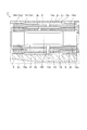
- FIG. 1 is a schematic cross-sectional view of a supercharger according to an embodiment of the present invention.
- FIG. 2 is a view for explaining the bearing structure of the present embodiment.
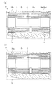
- FIG. 3A and FIG. 3B are diagrams for explaining a bearing structure according to a modification.
- FIG. 1 is a schematic sectional view of the supercharger C.
- the arrow L shown in FIG. 1 will be described as a direction indicating the left side of the supercharger C
- the arrow R will be described as a direction indicating the right side of the supercharger C.
- the supercharger C includes a supercharger main body 1.
- the turbocharger body 1 includes a bearing housing 2, a turbine housing 4 connected to the left side of the bearing housing 2 by a fastening mechanism 3, and a compressor housing 6 connected to the right side of the bearing housing 2 by fastening bolts 5. Have. These are integrated.
- a protrusion 2 a is provided on the outer peripheral surface of the bearing housing 2 in the vicinity of the turbine housing 4.
- the protrusion 2 a protrudes in the radial direction of the bearing housing 2.
- a projection 4 a is provided on the outer peripheral surface of the turbine housing 4 in the vicinity of the bearing housing 2.
- the protrusion 4 a protrudes in the radial direction of the turbine housing 4.
- the bearing housing 2 and the turbine housing 4 are fixed by fastening the protrusions 2 a and 4 a with the fastening mechanism 3.
- the fastening mechanism 3 includes a fastening band (for example, G coupling) that holds the protrusions 2a and 4a.
- the bearing housing 2 is provided with a bearing structure 7. Specifically, the bearing housing 2 is formed with a through hole 2b that penetrates in the left-right direction of the supercharger C (the axial direction of the shaft 8), and the shaft 8 is rotatably supported in the through hole 2b.
- the bearing structure 7 will be described in detail later.
- a turbine impeller 9 is integrally fixed to the left end portion (one end, first end portion) of the shaft 8, and this turbine impeller 9 is rotatably accommodated in the turbine housing 4.
- a compressor impeller 10 is integrally fixed to the right end portion (the other end, the second end portion) of the shaft 8, and the compressor impeller 10 is rotatably accommodated in the compressor housing 6.
- the compressor housing 6 has an intake port 11 formed therein.
- the intake port 11 opens to the right side of the supercharger C and is connected to an air cleaner (not shown).
- the bearing housing 2 and the compressor housing 6 are connected by the fastening bolt 5, the opposing surfaces of the housings 2 and 6 form a diffuser flow path 12 that pressurizes the air.
- the diffuser flow path 12 is formed in an annular shape from the radially inner side to the outer side of the shaft 8.
- the diffuser flow path 12 communicates with the intake port 11 via the compressor impeller 10 on the radially inner side.
- the compressor housing 6 is provided with a compressor scroll passage 13.
- the compressor scroll passage 13 is formed in an annular shape, and is located on the outer side in the radial direction of the shaft 8 (compressor impeller 10) than the diffuser passage 12.
- the compressor scroll passage 13 communicates with an intake port (not shown) of the engine. Further, the compressor scroll passage 13 communicates with the diffuser passage 12. Therefore, when the compressor impeller 10 rotates, air is sucked into the compressor housing 6 from the intake port 11 and is accelerated by the action of centrifugal force in the process of flowing between the blades of the compressor impeller 10, and the diffuser flow path 12 and the compressor The pressure is increased in the scroll passage 13 and guided to the intake port of the engine.
- a discharge port 14 is formed in the turbine housing 4.
- the discharge port 14 opens on the left side of the supercharger C and is connected to an exhaust gas purification device (not shown).
- the turbine housing 4 is provided with a flow path 15 and an annular turbine scroll flow path 16 positioned on the radially outer side of the shaft 8 (turbine impeller 9) with respect to the flow path 15.
- the turbine scroll passage 16 communicates with a gas inlet (not shown) through which exhaust gas discharged from an engine exhaust manifold (not shown) is guided.
- the turbine scroll flow path 16 communicates with the flow path 15. Therefore, the exhaust gas is guided from the gas inlet to the turbine scroll flow path 16 and is guided to the discharge port 14 via the flow path 15 and the turbine impeller 9.
- the exhaust gas rotates the turbine impeller 9.
- the rotational force of the turbine impeller 9 is transmitted to the compressor impeller 10 via the shaft 8, whereby the compressor impeller 10 rotates.
- the air is boosted by the rotational force of the compressor impeller 10 and guided to the intake port of the engine.
- FIG. 2 is a diagram for explaining the bearing structure 7 of the present embodiment, and shows a portion indicated by a broken line in FIG.
- the bearing structure 7 includes a through hole 2b formed in the bearing housing 2 and a bearing holder 18 that is an annular member accommodated in the through hole 2b.
- the bearing holder 18 has an annular (tubular) main body 18a.
- the main body 18a has a protrusion 18b on the turbine side.
- this protrusion 18b is referred to as a turbine-side protrusion.
- the turbine-side protrusion 18b is formed on the turbine impeller 9 side (left side in FIG. 2) of the outer peripheral surface 18c of the main body portion 18a with respect to the center position O of the bearing holder 18 in the axial direction of the shaft 8.
- the protrusion 18b is formed in an annular shape extending in the circumferential direction of the main body 18a, and protrudes outward in the radial direction of the main body 18a.
- the main body 18a has a protrusion 18d on the compressor side.
- this protrusion 18d is referred to as a compressor side protrusion.
- the compressor side protrusion 18d is formed on the compressor impeller 10 side of the outer peripheral surface 18c of the main body portion 18a with respect to the center position O.
- the compressor-side protrusion 18d is formed in an annular shape extending in the circumferential direction of the main body portion 18a, and projects outward in the radial direction of the main body portion 18a.
- An oil supply hole 18e is formed between the turbine side protrusion 18b and the compressor side protrusion 18d on the outer peripheral surface of the main body 18a.
- the oil supply hole 18e penetrates the main body portion 18a in the radial direction and guides the lubricating oil into the main body portion 18a.
- An oil passage 2c is formed in the bearing housing 2.
- the oil passage 2c communicates from the outside of the bearing housing 2 to the through hole 2b.
- the oil passage 2c guides the lubricating oil from the outside of the bearing housing 2 to the through hole 2b.
- the oil passage 2c has an opening 2d on the through hole 2b side. The opening 2d faces the portion of the outer peripheral surface 18c of the bearing holder 18 between the turbine side protrusion 18b and the compressor side protrusion 18d.
- a semi-floating metal (bearing) 19 is accommodated inside the main body 18a of the bearing holder 18.
- the semi-floating metal 19 is an annular member, and the shaft 8 is inserted therein.
- Bearing surfaces 19 a and 19 b are formed on the inner peripheral surface of the semi-floating metal 19.
- the bearing surfaces 19 a and 19 b are located on both end sides in the axial direction of the shaft 8.
- the oil hole 19 c opens between the bearing surfaces 19 a and 19 b on the inner peripheral surface of the semi-floating metal 19, penetrates the semi-floating metal 19 in the radial direction, and guides lubricating oil into the semi-floating metal 19. .
- the lubricating oil is guided to the through-hole 2b through the oil passage 2c, temporarily stored between the turbine-side protrusion 18b and the compressor-side protrusion 18d, and is supplied to the main body portion 18a through the oil supply hole 18e of the bearing holder 18. Led inside. Part of the lubricating oil introduced into the main body 18 a is supplied to the outer peripheral surface of the semi-floating metal 19 and functions as an oil damper that suppresses vibration of the semi-floating metal 19.
- a part of the lubricating oil introduced into the main body 18a is introduced into the semi-floating metal 19 through the oil hole 19c of the semi-floating metal 19 and supplied to the bearing surfaces 19a and 19b.
- the bearing surfaces 19a and 19b form an oil film of lubricating oil between the outer peripheral surfaces of the shaft 8, and rotatably support the shaft 8 by the oil film pressure.
- the bearing holder 18 has a hole 18f.
- the hole 18f penetrates the bearing holder 18 in the radial direction.
- the semi-floating metal 19 has a hole 19d.
- the hole 19d penetrates the semi-floating metal 19 in the radial direction.
- the hole 18f and the hole 19d are located at positions facing each other in the radial direction.
- the positioning member 20 is inserted in the radial direction of the shaft 8 with respect to both of the holes 18f and 19d.
- the positioning member 20 is composed of, for example, a pin or the like, and restricts the movement of the semi-floating metal 19 in the axial direction and the rotational direction of the shaft 8 with respect to the bearing holder 18.
- the positioning member 20 may be a member of not only a pin but another shape.
- the bearing holder 18 is provided, and the positioning member 20 regulates the movement of the semi-floating metal 19 with respect to the bearing holder 18. Therefore, before the bearing holder 18 and the semi-floating metal 19 are accommodated in the through hole 2b, the positioning member 20 can be inserted into the holes 18f and 19d, so that the positioning member 20 can be easily attached.
- the bearing holder 18 has a press-fitting portion 18g that is press-fitted into the through hole 2b.
- the press-fitting portion 18g is formed on the turbine-side protrusion 18b.
- the press-fit portion 18g has a slightly larger outer diameter before press-fitting than the inner diameter of the portion 2e of the through hole 2b facing the turbine-side protrusion 18b.
- the outer peripheral surface 18c on the compressor impeller 10 side (right side in FIG. 2) in the axial direction of the shaft 8, more strictly, between the compressor side protrusion 18d and the inner peripheral surface of the through hole 2b. Is formed with a gap S.
- the gap S is formed between the compressor side protrusion 18d and the inner peripheral surface of the through hole 2b, and the bearing holder 18 is press-fitted into the through hole 2b only by the turbine side protrusion 18b. Fixed.
- the contact area between the bearing holder 18 and the bearing housing 2 can be reduced, and heat transmitted from the bearing housing 2 to the semi-floating metal 19 via the bearing holder 18 can be suppressed.
- the contact area between the bearing holder 18 and the bearing housing 2 it is possible to suppress the propagation of vibration to the bearing housing 2 due to the rotation of the shaft 8.
- the press-fitting portion 18g is formed closer to the turbine impeller 9 than the axial center position O of the bearing holder 18, and the gap S is closer to the compressor impeller 10 than the center position O of the outer peripheral surface 18c of the bearing holder 18. Is formed.
- the compressor impeller 10 side is more vibrant due to the rotation of the shaft 8, and the compressor impeller 10 side of the shaft 8 is larger than the turbine impeller 9 side. Swing around greatly.
- the press-fit portion 18g is formed on the turbine impeller 9 side with respect to the center position O
- the gap S is formed on the compressor impeller 10 side with respect to the center position O, so that vibration associated with the rotation of the shaft 8 causes the bearing holder 18 to vibrate. It is possible to further suppress the transmission to the bearing housing 2 via.
- the bearing holder 18 may be inserted into the through-hole 2b from either the turbine impeller 9 side or the compressor impeller 10 side.
- the inner diameter of the portion through which the connecting portion of the turbine impeller 9 and the shaft 8 is inserted needs to be larger than the outer diameter of the bearing holder 18.
- the bearing holder 18 is inserted into the through hole 2b from the compressor impeller 10 side (right side in FIG. 2) of the through hole 2b.
- the outer diameter of the turbine-side protrusion 18b is set to be equal to or smaller than the minimum inner diameter of the through-hole 2b that is minimum on the compressor impeller 10 side than the turbine-side protrusion 18b.
- the minimum inner diameter is the inner diameter of the portion 2f facing the compressor side protrusion 18d in the through hole 2b, and the inner diameter of the portion 2f is larger than the inner diameter of the portion 2e facing the turbine side protrusion 18b.
- the turbine-side protrusion 18b can be inserted into the through-hole 2b without coming into contact with any other part until it comes into contact with the part 2e of the through-hole 2b facing the turbine-side protrusion 18b. Therefore, the press-fitting work into the through hole 2b of the bearing holder 18 becomes easy.
- FIG. 3 (a) and 3 (b) are diagrams for explaining the bearing structures 27 and 37 of the modified example.
- FIG. 3A shows a cross section of a portion corresponding to FIG. 2 in the bearing structure 27 of the first modification.
- FIG. 3B shows a cross section of a portion corresponding to FIG. 2 in the bearing structure 37 of the second modification.
- the bearing holder 18 is a press-fit portion formed on the compressor impeller 10 side (right side in FIG. 3A) with respect to the center position O. 28g. Further, the gap S is formed on the turbine impeller 9 side of the outer peripheral surface 18c of the bearing holder 18 with respect to the center position O.
- the press-fit portion 28g is formed on the compressor-side protrusion 18d.
- the press-fit portion 28g has a slightly larger outer diameter before press-fitting than the inner diameter of the portion 2f of the through hole 2b facing the compressor-side protrusion 18d.
- the gap S is formed between the turbine side protrusion 18b and the inner peripheral surface of the through hole 2b.
- the turbine impeller 9 side When comparing the turbine impeller 9 side in the bearing housing 2 and the compressor impeller 10 side, the turbine impeller 9 side is hotter.
- the press-fitting portion 28g is formed on the compressor impeller 10 side with respect to the center position O
- the gap S is formed on the turbine impeller 9 side with respect to the center position O, so that it is semi-floating from the bearing housing 2 via the bearing holder 18. It becomes possible to further suppress the heat transmitted to the metal 19.
- the turbine side protrusion 18b is not formed in the bearing structure 37 of the second modified example. Instead, the inner peripheral surface of the through hole 2b has an annular protrusion 2g on the turbine impeller 9 side (left side in FIG. 3B).
- the bearing holder 18 has a press-fit portion 38g formed as a portion facing the radially inner side of the annular protrusion 2g on the outer peripheral surface 18c.
- the press-fit portion 38g is formed so that the outer diameter of the press-fit portion 38g before press-fitting is larger than the inner diameter of the annular protrusion 2g.
- the annular protrusion 2g may be provided on the inner peripheral surface of the through hole 2b, and the bearing holder 18 may be press-fitted into the through hole 2b.
- the press-fitting portions 18g, 28g, and 38g are formed on either the turbine impeller 9 side or the compressor impeller 10 side from the center position O, and the gap S is on the other side. Is formed. However, the press-fit portions 18g, 28g, and 38g may be formed across the center position O.
- the turbine-side protrusion 18b and the compressor-side protrusion 18d are formed.
- the turbine-side protrusion 18b may not be provided, or the turbine-side protrusion 18b may be provided without the compressor-side protrusion 18d.
- the turbine side protrusion 18b and the compressor side protrusion 18d may not be provided.
- the press-fitting portions 18g, 28g, and 38g are formed by providing an annular protrusion in the through hole 2b.
- the outer diameter of the turbine-side protrusion 18b and the compressor-side protrusion 18d can be adjusted to easily form the gap S.
- the outer diameter of the turbine-side protrusion 18b is equal to or smaller than the minimum inner diameter of the through-hole 2b that is minimum on the compressor impeller 10 side than the turbine-side protrusion 18b.
- the outer diameter of the turbine-side protrusion 18b may be larger than the minimum inner diameter, and a plurality of press-fitting locations of the turbine-side protrusion 18b may be provided.
- the thrust bearing is provided as a member different from the semi-floating metal 19.
- a thrust bearing may be integrally provided on the end face of the semi-floating metal 19.
- the positioning member 20 restricts the movement of the semi-floating metal 19 in the axial direction and the rotational direction with respect to the bearing holder 18.
- the positioning member 20 may not restrict the movement in the axial direction.
- the semi-floating metal 19 can be prevented from coming into contact with a peripheral member such as a thrust bearing.
- a thrust bearing is provided integrally on the end face of the semi-floating metal 19, it is preferable to restrict movement in the axial direction.
- the lubricating oil is guided to the inside of the main body portion 18a through the oil passage 2c and the oil supply hole 18e of the bearing holder 18.
- the oil passage 2c may be branched so that the lubricating oil is guided directly to the turbine impeller 9 side and the compressor impeller 10 side of the semi-floating metal 19.
- the oil supply hole 18e and the oil hole 19c may be provided in the vicinity of the opening on the turbine impeller 9 side of the branched oil passage 2c and in the vicinity of the opening on the compressor impeller 10 side, respectively.
- channel extended in the axial direction or radial direction of the shaft 8 may be formed in the internal peripheral surface of the bearing surfaces 19a and 19b, for example.
- the present invention can be used for a bearing structure in which a shaft is supported by a semi-floating metal and a supercharger.
Landscapes
- Engineering & Computer Science (AREA)
- General Engineering & Computer Science (AREA)
- Mechanical Engineering (AREA)
- Physics & Mathematics (AREA)
- Fluid Mechanics (AREA)
- Supercharger (AREA)
- Sliding-Contact Bearings (AREA)
- Mounting Of Bearings Or Others (AREA)
- Structures Of Non-Positive Displacement Pumps (AREA)
Abstract
Description
Claims (7)
- 一端にタービンインペラが設けられ、他端にコンプレッサインペラが設けられたシャフトを収容するベアリングハウジング内に形成され、前記シャフトの軸方向に貫通する貫通孔と、
前記貫通孔に収容される環状部材である軸受ホルダーと、
前記軸受ホルダー内に収容される環状部材であって、内部に挿通される前記シャフトを支持するセミフローティングメタルと、
前記軸受ホルダーおよび前記セミフローティングメタルの双方に対して、前記シャフトの径方向に挿通され、前記軸受ホルダーに対して、前記シャフトの回転方向への前記セミフローティングメタルの移動を規制する位置決め部材と、
を備え、
前記軸受ホルダーは、前記貫通孔に圧入される圧入部を含み、
前記軸方向における前記軸受ホルダーの両端部の外周面の少なくとも一方と、前記貫通孔の内周面との間には間隙が形成されていることを特徴とする軸受構造。 - 前記圧入部は、前記軸受ホルダーにおける前記軸方向の中心位置よりも、前記タービンインペラ側および前記コンプレッサインペラ側のいずれか一方側に形成され、前記間隙は、前記軸受ホルダーの外周面のうち、前記中心位置よりも前記タービンインペラ側および前記コンプレッサインペラ側のいずれか他方側に形成されていることを特徴とする請求項1に記載の軸受構造。
- 前記軸受ホルダーは、
環状の本体部と、
前記中心位置よりも、前記本体部における前記タービンインペラ側の外周面に形成され、前記本体部の周方向に延在するタービン側突起と、
前記中心位置よりも、前記本体部における前記コンプレッサインペラ側の外周面に形成され、前記本体部の周方向に延在するコンプレッサ側突起と、
前記本体部の外周面のうち、前記タービン側突起および前記コンプレッサ側突起の間に開口し、前記本体部の内部に潤滑油を導く給油孔と、
を備え、
前記圧入部は、前記タービン側突起、および、前記コンプレッサ側突起のいずれか一方により形成され、前記間隙は、前記タービン側突起、および、前記コンプレッサ側突起のいずれか他方と前記貫通孔の内周面との間に形成されることを特徴とする請求項2に記載の軸受構造。 - 前記タービン側突起の外径は、前記貫通孔のうち、前記タービン側突起よりも前記コンプレッサインペラ側で最小となる内径以下であって、前記軸受ホルダーは、前記貫通孔のうち、前記コンプレッサインペラ側から前記貫通孔に挿通されることを特徴とする請求項3に記載の軸受構造。
- 前記圧入部は、前記中心位置よりも前記タービンインペラ側に形成されていることを特徴とする請求項2から4のいずれか1項に記載の軸受構造。
- 前記圧入部は、前記中心位置よりも、前記コンプレッサインペラ側に形成されていることを特徴とする請求項2から4のいずれか1項に記載の軸受構造。
- 前記請求項1から6のいずれか1項に記載の軸受構造を備える過給機。
Priority Applications (4)
| Application Number | Priority Date | Filing Date | Title |
|---|---|---|---|
| CN201580023532.XA CN106460917B (zh) | 2014-07-09 | 2015-06-26 | 轴承结构以及增压器 |
| DE112015003175.8T DE112015003175T5 (de) | 2014-07-09 | 2015-06-26 | Lagerstruktur und Turbolader |
| JP2016532880A JP6206592B2 (ja) | 2014-07-09 | 2015-06-26 | 軸受構造、および、過給機 |
| US15/335,940 US10443439B2 (en) | 2014-07-09 | 2016-10-27 | Bearing structure and turbocharger |
Applications Claiming Priority (2)
| Application Number | Priority Date | Filing Date | Title |
|---|---|---|---|
| JP2014-141173 | 2014-07-09 | ||
| JP2014141173 | 2014-07-09 |
Related Child Applications (1)
| Application Number | Title | Priority Date | Filing Date |
|---|---|---|---|
| US15/335,940 Continuation US10443439B2 (en) | 2014-07-09 | 2016-10-27 | Bearing structure and turbocharger |
Publications (1)
| Publication Number | Publication Date |
|---|---|
| WO2016006477A1 true WO2016006477A1 (ja) | 2016-01-14 |
Family
ID=55064115
Family Applications (1)
| Application Number | Title | Priority Date | Filing Date |
|---|---|---|---|
| PCT/JP2015/068493 WO2016006477A1 (ja) | 2014-07-09 | 2015-06-26 | 軸受構造、および、過給機 |
Country Status (5)
| Country | Link |
|---|---|
| US (1) | US10443439B2 (ja) |
| JP (2) | JP6206592B2 (ja) |
| CN (1) | CN106460917B (ja) |
| DE (1) | DE112015003175T5 (ja) |
| WO (1) | WO2016006477A1 (ja) |
Cited By (2)
| Publication number | Priority date | Publication date | Assignee | Title |
|---|---|---|---|---|
| CN107339252A (zh) * | 2017-07-19 | 2017-11-10 | 天津中隧通风机有限公司 | 离心风机调节门的自润滑轴承 |
| JP2020506334A (ja) * | 2017-02-08 | 2020-02-27 | アーベーベー ターボ システムズ アクチエンゲゼルシャフト | 流体力学的な軸方向固定手段を有する滑り軸受 |
Families Citing this family (4)
| Publication number | Priority date | Publication date | Assignee | Title |
|---|---|---|---|---|
| WO2017149671A1 (ja) * | 2016-03-01 | 2017-09-08 | 三菱重工業株式会社 | 軸受装置および排気タービン過給機 |
| US10190634B1 (en) * | 2017-07-11 | 2019-01-29 | GM Global Technology Operations LLC | Turbo-charger bearing |
| JP6510096B1 (ja) * | 2018-02-08 | 2019-05-08 | 三菱重工業株式会社 | 過給機 |
| JP7172508B2 (ja) | 2018-11-29 | 2022-11-16 | スズキ株式会社 | 船外機のステアリング装置 |
Citations (6)
| Publication number | Priority date | Publication date | Assignee | Title |
|---|---|---|---|---|
| JPS50140137U (ja) * | 1974-05-10 | 1975-11-18 | ||
| JPH0579345A (ja) * | 1991-09-18 | 1993-03-30 | Aisin Seiki Co Ltd | ターボチヤージヤの軸受装置 |
| US20110038717A1 (en) * | 2008-04-21 | 2011-02-17 | Yong Bok Lee | Oil-free turbocharger assembly |
| JP2011236966A (ja) * | 2010-05-10 | 2011-11-24 | Ihi Corp | 浮動ブッシュ、すべり軸受構造及び過給機 |
| JP2013002312A (ja) * | 2011-06-14 | 2013-01-07 | Denso Corp | ターボチャージャー |
| JP2013541676A (ja) * | 2010-11-09 | 2013-11-14 | ボーグワーナー インコーポレーテッド | 排気ガスターボチャージャ |
Family Cites Families (14)
| Publication number | Priority date | Publication date | Assignee | Title |
|---|---|---|---|---|
| JPS5084646A (ja) | 1973-11-28 | 1975-07-08 | ||
| JPS5084646U (ja) * | 1973-12-10 | 1975-07-19 | ||
| DE4230037A1 (de) | 1991-09-09 | 1993-03-11 | Aisin Seiki | Zentrifugal-aufladegeblaese |
| JP3365009B2 (ja) | 1993-11-18 | 2003-01-08 | 石川島播磨重工業株式会社 | ターボチャージャの軸受構造 |
| JP2007170296A (ja) | 2005-12-22 | 2007-07-05 | Ishikawajima Harima Heavy Ind Co Ltd | 過給機 |
| JP2009270613A (ja) | 2008-05-07 | 2009-11-19 | Toyota Motor Corp | ターボチャージャーの軸受構造 |
| JP2010138757A (ja) | 2008-12-10 | 2010-06-24 | Toyota Motor Corp | ターボチャージャ |
| CN103080499B (zh) * | 2010-09-13 | 2015-09-16 | 株式会社Ihi | 固定叶片式涡轮增压器 |
| US8841397B2 (en) * | 2011-03-25 | 2014-09-23 | Exxonmobil Chemical Patents Inc. | Vinyl terminated higher olefin polymers and methods to produce thereof |
| JP6145959B2 (ja) | 2011-07-12 | 2017-06-14 | 株式会社Ihi | ターボチャージャ |
| JP5904634B2 (ja) | 2012-01-30 | 2016-04-13 | ダイハツ工業株式会社 | ターボ過給機 |
| CN104379900B (zh) * | 2012-06-29 | 2017-09-22 | 株式会社Ihi | 增压器 |
| JP6660293B2 (ja) * | 2014-04-30 | 2020-03-11 | 株式会社Ihi | 過給機、および、過給機給油システム |
| CN106662154B (zh) * | 2014-07-09 | 2019-06-11 | 株式会社Ihi | 轴承构造以及增压器 |
-
2015
- 2015-06-26 CN CN201580023532.XA patent/CN106460917B/zh active Active
- 2015-06-26 DE DE112015003175.8T patent/DE112015003175T5/de active Pending
- 2015-06-26 JP JP2016532880A patent/JP6206592B2/ja active Active
- 2015-06-26 WO PCT/JP2015/068493 patent/WO2016006477A1/ja active Application Filing
-
2016
- 2016-10-27 US US15/335,940 patent/US10443439B2/en active Active
-
2017
- 2017-09-04 JP JP2017169272A patent/JP2018009704A/ja active Pending
Patent Citations (6)
| Publication number | Priority date | Publication date | Assignee | Title |
|---|---|---|---|---|
| JPS50140137U (ja) * | 1974-05-10 | 1975-11-18 | ||
| JPH0579345A (ja) * | 1991-09-18 | 1993-03-30 | Aisin Seiki Co Ltd | ターボチヤージヤの軸受装置 |
| US20110038717A1 (en) * | 2008-04-21 | 2011-02-17 | Yong Bok Lee | Oil-free turbocharger assembly |
| JP2011236966A (ja) * | 2010-05-10 | 2011-11-24 | Ihi Corp | 浮動ブッシュ、すべり軸受構造及び過給機 |
| JP2013541676A (ja) * | 2010-11-09 | 2013-11-14 | ボーグワーナー インコーポレーテッド | 排気ガスターボチャージャ |
| JP2013002312A (ja) * | 2011-06-14 | 2013-01-07 | Denso Corp | ターボチャージャー |
Cited By (3)
| Publication number | Priority date | Publication date | Assignee | Title |
|---|---|---|---|---|
| JP2020506334A (ja) * | 2017-02-08 | 2020-02-27 | アーベーベー ターボ システムズ アクチエンゲゼルシャフト | 流体力学的な軸方向固定手段を有する滑り軸受 |
| JP7050818B2 (ja) | 2017-02-08 | 2022-04-08 | エービービー スウィッツァーランド リミテッド | 流体力学的な軸方向固定手段を有する滑り軸受 |
| CN107339252A (zh) * | 2017-07-19 | 2017-11-10 | 天津中隧通风机有限公司 | 离心风机调节门的自润滑轴承 |
Also Published As
| Publication number | Publication date |
|---|---|
| CN106460917A (zh) | 2017-02-22 |
| JP2018009704A (ja) | 2018-01-18 |
| JPWO2016006477A1 (ja) | 2017-04-27 |
| US10443439B2 (en) | 2019-10-15 |
| US20170044933A1 (en) | 2017-02-16 |
| CN106460917B (zh) | 2019-02-05 |
| JP6206592B2 (ja) | 2017-10-04 |
| DE112015003175T5 (de) | 2017-03-16 |
Similar Documents
| Publication | Publication Date | Title |
|---|---|---|
| JP6206592B2 (ja) | 軸受構造、および、過給機 | |
| US10677287B2 (en) | Bearing structure and turbocharger | |
| JP6642586B2 (ja) | 軸受構造、および、過給機 | |
| JP7107371B2 (ja) | 軸受構造および過給機 | |
| WO2016027617A1 (ja) | 軸受構造、および、過給機 | |
| US10557377B2 (en) | Turbocharger | |
| JP6248628B2 (ja) | 過給機 | |
| WO2017026292A1 (ja) | 軸受構造、および、過給機 | |
| JP6597780B2 (ja) | シール構造および過給機 | |
| US20190107052A1 (en) | Turbocharger | |
| WO2017203962A1 (ja) | 過給機 | |
| JPWO2017026293A1 (ja) | 軸受構造、および、過給機 | |
| KR102192746B1 (ko) | 과급기 | |
| WO2015190362A1 (ja) | 過給機 | |
| JP6512296B2 (ja) | 軸受構造および過給機 | |
| WO2022118606A1 (ja) | 軸受構造、および、過給機 | |
| JP5987476B2 (ja) | 過給機 | |
| US11898457B2 (en) | Bearing and turbocharger | |
| JP6912003B2 (ja) | 遠心圧縮機 | |
| WO2020059370A1 (ja) | 軸受構造、および、過給機 |
Legal Events
| Date | Code | Title | Description |
|---|---|---|---|
| 121 | Ep: the epo has been informed by wipo that ep was designated in this application |
Ref document number: 15819518 Country of ref document: EP Kind code of ref document: A1 |
|
| ENP | Entry into the national phase |
Ref document number: 2016532880 Country of ref document: JP Kind code of ref document: A |
|
| WWE | Wipo information: entry into national phase |
Ref document number: 112015003175 Country of ref document: DE |
|
| 122 | Ep: pct application non-entry in european phase |
Ref document number: 15819518 Country of ref document: EP Kind code of ref document: A1 |