WO2016006399A1 - ステッチ加飾付き内装部品及びその成形型 - Google Patents
ステッチ加飾付き内装部品及びその成形型 Download PDFInfo
- Publication number
- WO2016006399A1 WO2016006399A1 PCT/JP2015/067406 JP2015067406W WO2016006399A1 WO 2016006399 A1 WO2016006399 A1 WO 2016006399A1 JP 2015067406 W JP2015067406 W JP 2015067406W WO 2016006399 A1 WO2016006399 A1 WO 2016006399A1
- Authority
- WO
- WIPO (PCT)
- Prior art keywords
- stitch
- skin material
- stitch decoration
- base material
- decoration
- Prior art date
- Legal status (The legal status is an assumption and is not a legal conclusion. Google has not performed a legal analysis and makes no representation as to the accuracy of the status listed.)
- Ceased
Links
Images





Classifications
-
- B—PERFORMING OPERATIONS; TRANSPORTING
- B29—WORKING OF PLASTICS; WORKING OF SUBSTANCES IN A PLASTIC STATE IN GENERAL
- B29C—SHAPING OR JOINING OF PLASTICS; SHAPING OF MATERIAL IN A PLASTIC STATE, NOT OTHERWISE PROVIDED FOR; AFTER-TREATMENT OF THE SHAPED PRODUCTS, e.g. REPAIRING
- B29C51/00—Shaping by thermoforming, i.e. shaping sheets or sheet like preforms after heating, e.g. shaping sheets in matched moulds or by deep-drawing; Apparatus therefor
- B29C51/12—Shaping by thermoforming, i.e. shaping sheets or sheet like preforms after heating, e.g. shaping sheets in matched moulds or by deep-drawing; Apparatus therefor of articles having inserts or reinforcements
-
- B—PERFORMING OPERATIONS; TRANSPORTING
- B29—WORKING OF PLASTICS; WORKING OF SUBSTANCES IN A PLASTIC STATE IN GENERAL
- B29C—SHAPING OR JOINING OF PLASTICS; SHAPING OF MATERIAL IN A PLASTIC STATE, NOT OTHERWISE PROVIDED FOR; AFTER-TREATMENT OF THE SHAPED PRODUCTS, e.g. REPAIRING
- B29C51/00—Shaping by thermoforming, i.e. shaping sheets or sheet like preforms after heating, e.g. shaping sheets in matched moulds or by deep-drawing; Apparatus therefor
- B29C51/26—Component parts, details or accessories; Auxiliary operations
- B29C51/30—Moulds
- B29C51/36—Moulds specially adapted for vacuum forming, Manufacture thereof
-
- B—PERFORMING OPERATIONS; TRANSPORTING
- B60—VEHICLES IN GENERAL
- B60R—VEHICLES, VEHICLE FITTINGS, OR VEHICLE PARTS, NOT OTHERWISE PROVIDED FOR
- B60R13/00—Elements for body-finishing, identifying, or decorating; Arrangements or adaptations for advertising purposes
- B60R13/02—Internal Trim mouldings ; Internal Ledges; Wall liners for passenger compartments; Roof liners
Definitions
- the present invention relates to an interior part with a stitch decoration in which a stitch decoration part is formed on a skin material, which includes a base material and a skin material bonded to the surface of the base material, and a molding die thereof.
- the surface of a hard resin base material is covered with a soft synthetic resin skin material, and a leather-like texture pattern is applied to the skin material, and leather texture pieces with a texture pattern are sewn together with threads.
- the stitch pattern By applying the stitch pattern, the design is improved and the device is designed to give a sense of luxury and softness.
- a stitch pattern is formed by sewing a thread, for example, a step of forming a groove groove corresponding to the thread stitch on the skin material and a stitch pattern of the sewing thread is applied to the groove groove.
- attaching the skin material which gave the stitch pattern to a base material are needed (for example, refer patent document 1).
- the interior part with stitch decoration in which the stitch pattern by sewing the thread is formed on the skin material, the molding process compared to the interior part that does not have the stitch pattern, which is sufficient if there is a process to adhere the skin material to the base material
- the number of processes will increase, and the cost of equipment will increase. Therefore, the interior part with stitch decoration has a problem that the production cost is greatly increased because only the stitch pattern is applied.
- stitch decoration portion an interior part with stitch decoration in which a skin material is compressed and deformed to form a pseudo stitch pattern (hereinafter referred to as “stitch decoration portion”) is also conceivable, but includes a fine stitch pattern. It has not been easy to form a stitch decoration portion that approximates a stitch pattern formed by sewing a thread. Therefore, as shown in FIGS. 14 and 15, in Patent Document 2, the base material 101 provided with the stitch pattern irregularities 102 is set in a vacuum forming die 108 (FIG. 14A), and the base material 101.
- the technique of Patent Document 2 has the following problems. That is, the technique of Patent Document 2 includes a step of vacuum-bonding a thermoplastic sheet 103 (corresponding to a skin material) to a base material 101 provided with stitch pattern irregularities 102 in advance (FIGS. 14A and 14B), stitching Only the stitch pattern 104 of the vacuum molded product 100 is pressed by a press die 107 in which the pattern 105 and its fine thread pattern 106 are engraved, and the clear stitch pattern 105 and the thread pattern 106 are transferred to the surface of the vacuum molded product 100. Since the process (FIG. 14C) is provided, at least two forming processes are necessary, and the problem of increasing the production cost applied to the stitch decoration part has not been solved.
- the vacuum molded product 100 in which the rough outline 104B of the stitch pattern 104 is formed is pressed by a press die 107 in which a stitch pattern 105 and its fine thread pattern 106 are engraved, and vacuum is applied. Since the step of transferring the clear stitch pattern 105 and the thread pattern 106 to the surface of the molded article 100 is provided, in the vacuum molded article 100, the relative stitch pattern 105 and the thread pattern 106 are relative to the rough outline 104B of the stitch pattern 104. Misalignment is likely to occur.
- the present invention has been made to solve the above-described problems, and can reduce the production cost applied to the stitch decoration part and can improve the surface quality (appearance) of the stitch decoration part. And it aims at providing the shaping
- One aspect of the present invention for solving the above problems is a stitch decoration comprising a base material and a skin material bonded to the surface of the base material, wherein a stitch decoration portion is formed on the skin material. It is an interior part, and the stitch decoration part is formed by compressing and deforming the skin material toward the base material side when the heated skin material is pressed and bonded to the base material surface. The purpose.
- the stitch decoration part includes a pseudo thread part in which the skin material is formed in a sewing shape in the longitudinal direction, and a longitudinal direction of the pseudo thread part. It is preferable that the skin material includes a sag portion that is located on both sides and is inclined toward the base material side.
- the interior part with stitch decoration includes the stitch decoration part at a position where a vehicle occupant can visually check in a seating posture.
- the sagging portion is formed to be asymmetrically inclined with respect to a surface straight line of the base material surface passing through the pseudo yarn portion.
- the “surface straight line on the surface of the base material passing through the pseudo-yarn portion” means that it passes through the apex of the pseudo-yarn portion on the cross section orthogonal to the longitudinal direction of the pseudo-yarn portion and is orthogonal to the tangent line on the surface of the base material. Means normal.
- the surface of the base material passing through the pseudo yarn portion of the occupant side sag portion located on the same side as the occupant with respect to the pseudo yarn portion.
- the inclination angle with respect to the surface straight line is formed larger than the inclination angle with respect to the surface straight line of the substrate surface passing through the pseudo yarn portion of the opposite side sag portion located on the opposite side of the occupant with respect to the pseudo yarn portion. Is preferred.
- the inclination angle of the occupant side sag portion is formed so as to increase as the pseudo yarn portion is separated from the occupant side in the longitudinal direction. It is preferred that
- the stitch decoration part is a double stitch formed by sandwiching an inner stitch part between two rows of outer stitch parts. Preferably there is.
- the inclination angle of the occupant side sag portion in the second outer stitch portion that is located apart from the occupant side among the two rows of outer stitch portions is preferably formed to be larger than the inclination angle of the occupant side sag portion in the first outer stitch portion located close to the occupant side.
- the mold for an interior part with stitch decoration described in any one of (1) to (7), is A vacuum forming die provided with a base material holding die for holding the base material and a skin material pressing die for pressing the skin material against the surface of the base material, and the skin material pressing die presses the skin material. It is intended that a protrusion for forming the stitch decoration portion is provided on the skin material pressing portion.
- an electroformed shell is formed on the skin material pressing portion along the skin material pressing surface that presses the skin material,
- the electroformed shell is preferably provided with the protrusion.
- the stitch model decorating part includes the prototype model for transferring the tank model in which the electroformed shells are stacked. It is preferable that the hole center line of the needle hole portion forming the seam is formed so as to be inclined in a direction approaching the skin material pressing direction from a surface straight line with respect to the base material reference surface of the prototype model.
- an interior part with a stitch decoration and a molding die thereof that can reduce the production cost applied to the stitch decoration part and improve the surface quality (look) of the stitch decoration part.
- FIG. 2 is a detailed perspective view of part A shown in FIG. 1. It is a detailed sectional view of the stitch decoration part in FIG.
- FIG. 2 is a cross-sectional comparison view of a first outer stitch portion in a BB cross section and a DD cross section shown in FIG. 1.
- FIG. 7 is a schematic cross-sectional view for explaining a procedure for forming a needle hole portion corresponding to a seam in the prototype model shown in FIG.
- FIG. 8 is a detailed view of a protrusion in FIG. 7.
- FIG. 8 is a partial cross-sectional view showing a direction in which a needle hole portion (FIG. 7) corresponding to a stitch of a stitch decoration portion in the BB cross section shown in FIG. 1 is formed.
- FIG. 8 is a partial cross-sectional view showing a direction in which a needle hole portion (FIG. 7) corresponding to a stitch of a stitch decoration portion in the CC cross section shown in FIG. 1 is formed.
- FIG. 8 is a partial cross-sectional view showing a direction in which a needle hole portion (FIG. 7) corresponding to a stitch of a stitch decoration portion in the DD cross section shown in FIG. 1 is formed.
- FIG. 1 It is typical sectional drawing explaining the shaping
- an embodiment of an interior part with stitch decoration and its mold according to the present invention will be described in detail with reference to the drawings.
- the structure of the interior part with stitch decoration according to the present embodiment and the structure of the stitch decoration part will be described, and then the structure of the mold of the interior part with stitch decoration according to another embodiment and the skin in the mold A method for manufacturing the material pressing mold will be described.
- a method for forming an interior part with stitch decoration using a mold, in particular, a process for forming a stitch decoration portion will be described.
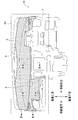
- FIG. 1 the front view of the interior component with a stitch decoration which is embodiment which concerns on this invention is shown.
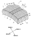
- FIG. 2 is a detailed perspective view of a portion A shown in FIG.
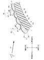
- FIG. 3 shows a detailed cross-sectional view of the stitch decoration portion in FIG.
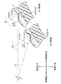
- FIG. 4 is a cross-sectional comparison view of the first outer stitch portion in the BB cross section and the DD cross section shown in FIG.
- the interior part 10 with stitch decoration is an instrument panel mounted in front of a driver seat and a passenger seat of a vehicle, and is a substantially rectangular interior part.
- the interior part 10 with stitch decoration is composed of a base material 1 made of a hard resin formed in a required shape, and a skin material 2 made of a soft thermoplastic resin bonded to the surface of the base material. .
- the skin material 2 is extended to the vehicle left-right direction edge part in the vehicle upper direction of the base material 1, as shown by the dot display.
- a stitch decoration portion 3 extending in the vehicle left-right direction is formed.
- the skin material 2 is composed of a skin 21 excellent in surface side ductility and a foam layer 22 on the base material side.
- a pseudo stitch pattern (stitch decoration portion 3) formed by compressing and deforming the skin material 2 is formed on the skin material 2 .
- a leather-like texture pattern is formed on the skin 21 in order to give a sense of quality and softness.
- the substrate 1 is made of, for example, an injection-molded polypropylene (PP) resin.
- the skin 21 is made of, for example, an olefin elastomer (TPO) having a thickness of about 0.5 to 0.8 mm.
- the foam layer 22 is made of, for example, polypropylene foam (PPF) having a thickness of about 3 to 4 mm.
- the stitch decoration portion 3 has a double stitch structure in which two rows of outer stitch portions 3A and 3B are formed with the inner stitch portion 3C interposed therebetween.
- the outer stitch portion 3A located at the rear of the vehicle is referred to as a first outer stitch portion
- the outer stitch portion 3B located at the front of the vehicle is referred to as a second outer stitch portion.
- the first outer stitch portion 3A and the second outer stitch portion 3B are provided with pseudo-yarn portions 31, 32 in which stitches 3A1, 3B1 are formed at a predetermined pitch in the longitudinal direction.
- the pseudo yarn portions 31 and 32 have a substantially arc-shaped cross section. Spiral threads are formed on the arc surfaces of the pseudo yarn portions 31 and 32.
- a sag portion 31a in which the skin 21 of the skin material 2 is located on both sides in the longitudinal direction of the pseudo yarn portions 31 and 32 and is inclined toward the base material side, 31b, 32a and 32b are provided.
- the base-side tips of the sagging portions 31a, 31b, 32a, 32b intersect the arc surface base ends of the pseudo yarn portions 31, 32.
- the sagging portions 31a, 31b, 32a, 32b are formed so as to be asymmetrically inclined with respect to the plane straight lines p1, p2 of the base material surface 11 passing through the pseudo yarn portions 31, 32.
- planar straight lines p1 and p2 of the base material surface 11 passing through the pseudo yarn portions 31 and 32 are cross sections orthogonal to the longitudinal direction of the pseudo yarn portions 31 and 32 and the pseudo yarn portions 31 and 32. It means a normal passing through the apex and orthogonal to the tangent to the substrate surface 11.
- the sagging portions 31a, 31b, 32a, 32b are occupant side sagging portions 31a, 32a located on the same side as the occupant m seated in the driver seat or the passenger seat with respect to the pseudo yarn portions 31, 32, and the pseudo yarn portion. 31 and 32, it consists of opposite side sag portions 31b and 32b located on the opposite side of the passenger m.
- the first outer stitch portion 3A is formed at a position that can be easily seen by the occupant m seated in the driver seat or the passenger seat, the surface straight line p1 of the base material surface 11 passing through the pseudo yarn portion 31 of the occupant side sag portion 31a.
- the inclination angle ⁇ 1 is approximately the same as the inclination angle ⁇ 2 with respect to the surface straight line p1 of the substrate surface 11 passing through the pseudo yarn portion 31 of the opposite side sag portion 31b.
- the second outer stitch portion 3B is formed at a position that is difficult to see from the occupant m seated in the driver seat or the passenger seat, the surface of the substrate surface 11 that passes through the pseudo yarn portion 32 of the occupant side sag portion 32a.
- the inclination angle ⁇ 1 with respect to the straight line p2 is formed larger than the inclination angle ⁇ 2 with respect to the surface straight line p2 of the substrate surface 11 that passes through the pseudo yarn portion 32 of the opposite side sag portion 32b.
- the pseudo yarn portion 32 that is difficult to see by being sandwiched between the sagging portions 32a and 32b located on both sides in the longitudinal direction of the pseudo yarn portion 32 according to the viewing direction is seen in the sagging portions 32a and 32b. Is changed so that the stitches 3A1 and 3B1 of the pseudo yarn portions 31 and 32 in the stitch decoration portion 3 can be easily seen.
- the stitches 3B1 of the pseudo-yarn portion 32 easy to see, an impression of the stitch pattern by sewing the thread can be given to the viewer.
- the inclination angle ⁇ 1 of the occupant side sag portion 32a in the second outer stitch portion 3B is formed larger than the inclination angle ⁇ 1 of the occupant side sag portion 31a in the first outer stitch portion 3A. Therefore, it seems that the occupant side sag portions 31a and 32a in the first outer stitch portion 3A and the second outer stitch portion 3B are formed with inclined surfaces having approximate inclination angles. As a result, the occupant m in the sitting posture can clearly see the pseudo yarn portion 32 in the second outer stitch portion 3B as much as the pseudo yarn portion 31 in the first outer stitch portion 3A.
- the inclination angle ⁇ 1 ( ⁇ 11, ⁇ 12) of the occupant side sag portion 31a is increased as the pseudo yarn portion 31 is separated from the occupant m side in the longitudinal direction. It is formed to be large.
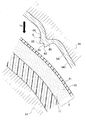
- the inclination angle ⁇ 1 ( ⁇ 13) in the DD cross section (see FIG. 1) at a position separated from the occupant m in the sitting posture is the BB cross section (see FIG. 1) in the position close to the occupant m in the sitting posture.
- the inclination angle ⁇ 1 ( ⁇ 11) is larger than that in the reference). Therefore, from the viewpoint m1 of the occupant m, the pseudo yarn portion 313 (31) in the DD cross section can be clearly seen to the same extent as the pseudo yarn portion 311 (31) in the BB cross section.
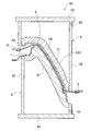
- the molding die 50 includes a base material holding mold 4 that holds the base material 1 and a skin material pressing that presses the heated skin material 2 w (2) on the surface of the base material.
- the skin material pressing die 5 is provided with a protrusion 6 that forms a stitch decoration portion 3 on a skin material pressing portion 51 that presses the skin material 2w (2).
- the skin material 2w (2) is formed in a substantially rectangular sheet that can correspond to the skin material adhesion range of the interior part 10 with stitch decoration, and the end portion thereof is gripped by the gripping device 8, and is not shown in the drawing. After being heated by the apparatus, the substrate surface is coated.
- the base material holding mold 4 is formed with a base material holding portion 41 that holds the base material 1 along the shape of the base material.
- a plurality of vacuum suction holes (not shown) are formed in the base material holding part 41 at predetermined intervals.
- a lower frame portion 42 Connected to the lower end of the base material holding portion 41 is a lower frame portion 42 that forms an air passage 44 for sending air sucked from the vacuum suction hole to a suction pump (not shown).
- the lower frame portion 42 is connected to the lower base 43.
- a skin material pressing portion 51 that presses the skin material 2w (2) on the surface of the base material is formed along the base material shape.
- a plurality of vacuum suction holes (not shown) are formed at predetermined intervals.
- an upper frame portion 52 Connected to the upper end of the skin material pressing portion 51 is an upper frame portion 52 that forms an air passage 54 for sending air sucked from the vacuum suction hole to a suction pump (not shown).
- the upper frame portion 52 is connected to the upper base 53.
- the skin material pressing part 51 is formed with a stitch decoration projection 6 at a position corresponding to the stitch decoration part 3 shown in FIG.
- the lower surface of the skin material pressing portion 51 including the protruding portion 6 is covered with a porous electroformed shell 5A with a predetermined thickness.
- a porous electroformed shell 5A with a predetermined thickness.
- fine holes for vacuum suction are appropriately formed.
- a leather-like texture pattern is formed on the skin material pressing surface 5A1 of the electroformed shell 5A.
- FIG. 6 is a schematic cross-sectional view for explaining a procedure for manufacturing the skin material pressing die of the molding die shown in FIG.
- FIG. 7 is a schematic cross-sectional view for explaining a procedure for forming a needle hole portion corresponding to a stitch in the prototype model shown in FIG.
- FIG. 8 shows a detailed view of the protrusion in FIG.
- FIG. 9 is a partial cross-sectional view showing a direction in which the needle hole portion (FIG. 7) corresponding to the stitch of the stitch decoration portion in the BB cross section shown in FIG. 1 is formed.
- FIG. 6 is a schematic cross-sectional view for explaining a procedure for manufacturing the skin material pressing die of the molding die shown in FIG.
- FIG. 7 is a schematic cross-sectional view for explaining a procedure for forming a needle hole portion corresponding to a stitch in the prototype model shown in FIG.
- FIG. 8 shows a detailed view of the protrusion in FIG.
- FIG. 9 is a partial cross-sectional view showing
- FIG. 10 is a partial cross-sectional view showing the direction in which the needle hole portion (FIG. 7) corresponding to the stitch of the stitch decoration portion in the CC cross section shown in FIG. 1 is formed.
- FIG. 11 is a partial cross-sectional view showing the direction in which the needle hole portion (FIG. 7) corresponding to the stitch of the stitch decoration portion in the DD cross section shown in FIG. 1 is formed.
- the skin material pressing die 78 (5) of the molding die 50 is manufactured by the following procedure.
- the prototype model 71 such as resin or gypsum
- the base material reference surface 711 having the same shape as the base material surface 11 is processed (FIG. 6A).
- the skin material 72 is affixed to the base material reference surface 711 of the prototype model 71 (FIG. 6B).
- FIG. 7 after forming the needle hole part 712 at the position where the stitches 3A1 and 3B1 of the stitch decoration part 3 shown in FIG. It is affixed (FIGS. 7A to 7C).
- the perforating needle 713 is pierced from the top of the skin material 72, and the skin material 72 is also perforated (FIG. 7D).
- a thread 714 for sewing is inserted in the needle hole portion 712 in a folded manner (FIG. 7E).
- a resin 716 is injected into the bottom of a groove 715 in which a sewing thread 714 is folded in two (FIGS. 8A and 8B), and the bottom 718 is micro-R with a dedicated tool 717. (About 0.3 mm) is formed.
- the hole center lines q1 and q2 of the needle hole portion 712 are formed so as to be inclined in a direction closer to the skin material pressing direction T1 than the plane straight lines p1 and p2 with respect to the base material reference surface 711 of the prototype model 71. Specifically, as shown in FIG. 9 to FIG. 11, it is set for each part according to the arrangement relationship of the stitch decorating part with respect to the occupant and the inclination state of the base material reference surface with respect to the skin material pressing direction T1.
- the needle hole portion corresponding to the stitch decoration portion 3 (cross section BB in FIG. 1) that is disposed at a position close to the occupant and has a gentle inclination of the base material reference surface is the first hole portion.
- the inclination angle ⁇ 1 between the hole center line q1 of the needle hole part 712a (712) of the outer stitch part and the surface straight line p1 of the base material reference surface is 10 degrees, and the needle hole part 712b (712) of the second outer stitch part
- the inclination angle ⁇ 2 between the hole center line q2 and the surface straight line p2 of the base material reference surface is 30 degrees.
- the stitch decoration portion 3 (CC cross section in FIG. 1) is disposed at a position slightly away from the occupant in the longitudinal direction, and the inclination of the base material reference surface gradually increases.
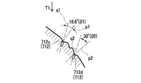
- the inclination angle ⁇ 1 between the hole center line q1 of the needle hole portion 712c (712) of the first outer stitch portion and the surface straight line p1 of the base material reference surface is 16.6 degrees
- the second outer stitch The inclination angle ⁇ 2 between the hole center line q2 of the needle hole portion 712d (712) and the surface straight line p2 of the base material reference surface is 30 degrees.
- the needle corresponding to the stitch decoration portion 3 (DD cross section in FIG. 1) which is arranged at a position far away from the occupant in the longitudinal direction and in which the inclination of the base material reference surface is further increased.
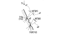
- the hole portion has an inclination angle ⁇ 1 between the hole center line q1 of the needle hole portion 712e (712) of the first outer stitch portion and the surface straight line p1 of the base material reference surface is 20 degrees, and the needle of the second outer stitch portion
- the inclination angle ⁇ 2 between the hole center line q2 of the hole portion 712f (712) and the surface straight line p2 of the base material reference surface is 30 degrees.
- a silicon resin or the like is injected into the gap to produce the inverted model 73.
- the tank model 75 is transferred from the inversion model 73.
- the tank model 75 is put into the electrodeposition plating tank 77, and the electroformed shell 76 (5A) is laminated
- the electroformed shell 76 (5A) is assembled to the skin material pressing die 78 (5).
- FIG. 12 is a schematic cross-sectional view for explaining a molding procedure using a molding die for the interior part with stitch decoration shown in FIG.
- FIG. 13 is a partial cross-sectional view showing the molding process (before molding) of the second outer stitch portion shown in FIG.
- FIG. 14 is a partial cross-sectional view showing a molding process (during molding) of the second outer stitch portion shown in FIG.
- FIG. 15 is a partial cross-sectional view showing the molding process (after molding) of the second outer stitch portion shown in FIG.
- the molding die 50 sets the base material holding die 4 and the skin material pressing die 5 in the mold open state. Further, the base material 1 is placed between the base material holding mold 4 and the skin material pressing mold 5 on the base material holding mold 4. The skin material 2 w is gripped at both ends by the gripping device 8.
- the skin material 2 w is placed on the surface of the base material placed on the base material holding mold 4.
- the position of the gripping device 8 is set in consideration of the elongation of the skin material 2w.
- the skin material pressing die 5 is lowered in the direction of the arrow T1, and the base material holding die 4 and the skin material pressing die 5 are brought into a clamped state. set.
- the skin material pressing die 5 vacuum-sucks the skin material 2w while being held in the clamped state, and then the base material holding die 4 vacuum-sucks the skin material 2w to the base material side.
- the skin material 2w is adhered to the base material 1, and at the same time, the embossed pattern is transferred to the skin material 2w to form the stitch decoration portion 3.
- the skin material pressing die 5 rises in the direction of the arrow T2, takes out the base material 1 to which the skin material 2w is bonded from the base material holding die 4, and cuts unnecessary skin material.
- the interior part 10 with stitch decoration is formed.
- the skin material pressing die 5 is moved up and down to form the mold open state and the mold clamping state, but the base material holding die 4 or both the base material holding die 4 and the skin material pressing die 5 are lifted and lowered. Also good.
- the skin material pressing portion 51 of the skin material pressing die 5 is formed with a protruding portion 6 for stitch decoration.
- the protrusion 6 is formed integrally with the electroformed shell 5A.
- the protrusion 6 is formed with a substantially arc-shaped forming portion (pseudo yarn forming portion) 61 that forms the pseudo yarn portion 32, an occupant side sag forming portion 64 that forms the occupant side sag portion 32a, and an opposite side sag portion 32b. And an opposite side sag forming portion 65.
- An intersecting portion 62 between the substantially arc-shaped forming portion (pseudo yarn forming portion) 61 and the occupant side sag forming portion 64, and an intersecting portion 63 between the substantially arc-shaped forming portion (pseudo yarn forming portion) 61 and the opposite sag portion 32b are: Each has an acute-angled cross section, and a minute R is formed at the tip.
- the skin material 2 is covered on the base material surface 11 of the base material 1 placed on the base material holding part 41.
- the protruding portion 6 presses the skin material 2 before the skin material pressing surface 5A1 of the electroformed shell 5A comes into contact with the skin material 2. Since the skin material 2 is composed of the skin 21 and the foam layer 22 excellent in ductility, when the protrusion 6 presses the skin material 2, the foam layer 22 is compressed and deformed while the skin 21 is stretched. At that time, the skin material 2 is pressed by the substantially arc-shaped forming portion (pseudo yarn forming portion) 61 of the protrusion 6 to form the pseudo yarn portion 32, and is pressed by the occupant side sag forming portion 64 of the protrusion 6.
- the occupant side sag portion 32a is formed, and is pressed by the opposite side sag forming portion 65 of the projection 6 to form the opposite side sag portion 32b.
- the second outer stitch portion 3B is formed.
- the pseudo yarn portion 32, the occupant-side sag portion 32a, and the opposite-side sag portion 32b are vacuum-sucked through the electroformed shell 5A, so that they can become familiar with the respective molding portions of the projection portion 6.
- the skin material pressing surface 5A1 of the electroformed shell 5A presses the skin material 2, whereby the skin material 2 is adhered to the base material surface 11, and the embossed pattern is transferred to the skin 21 of the skin material 2.
- the needle hole portion 712 to which the protrusion 6 is transferred is closer to the skin material pressing direction T1 than the surface straight line p2 with respect to the base material reference surface 711 of the prototype model 71. It is drilled at an angle. Therefore, as shown in FIG. 14, the protrusion 6 is formed by inclining by an inclination angle ⁇ 2 between the surface straight line p2 with respect to the base material contact surface 411 of the base material holding part 41 and the hole center line q2 of the needle hole part 712. Has been.
- the negative angle amount u2 with respect to the skin material 2 is suppressed to an amount of 10 to 15% or less of the thickness of the skin material 2. If the negative angle amount u2 is 10 to 15% or less of the thickness of the skin material 2, it is a level at which scratches and the like can be easily suppressed by elastic deformation of the skin material 2.
- the skin material pressing portion 51 is raised in the direction of the arrow T2. Since the skin material 2 is a thermoplastic resin, even if the skin material pressing portion 51 is separated, the stitch decoration portion 3 (3B) formed by the projection portion 6 can maintain the state.
- the stitch decoration part 3 presses the heated skin material 2 against the substrate surface 11. Since the skin material 2 is formed by compressing and deforming the skin material 2 toward the base material side, the process of pressing the skin material 2 against the base material surface 11 and bonding the skin material 2 and compressing the skin material 2 toward the base material side. The process of forming the stitch decoration part 3 can be united into one, and the production cost concerning the stitch decoration part 3 can be reduced. Further, the stitch decoration portion 3 is formed by compressing and deforming the skin material 2 toward the base material side when the heated skin material 2 is pressed and bonded to the base material surface 11, so that the stitch pattern or pattern of the stitch is changed. It is possible to suppress the possibility of problems in terms of surface quality (appearance) of the stitch decoration part 3 such as scratches.
- the stitch decoration part 3 is located in the longitudinal direction both sides of the pseudo yarn parts 31 and 32 in which the skin material 2 was formed in a sewing shape in the longitudinal direction and the pseudo yarn parts 31 and 32. Since the skin material 2 includes the sag portions 31a, 31b, 32a, and 32b that are inclined toward the base material side, the sag portions 31a, 31b, 32a, and 32b that are located on both sides in the longitudinal direction of the pseudo yarn portions 31 and 32 Thus, the pseudo yarn portions 31 and 32 can be formed while suppressing the local elongation of the skin material 2. Therefore, it is possible to reduce the risk of problems in surface quality (appearance) such as tearing of the skin material 2 in the stitch decoration portion 3.
- the interior part 10 with a stitch decoration is the vehicle interior part 10 provided with the stitch decoration part 3 in the position which the passenger
- the stitches 3B1 of the pseudo-yarn portion 32 By making the stitches 3B1 of the pseudo-yarn portion 32 easy to see, an impression of the stitch pattern by sewing the thread can be given to the viewer. As a result, the stitch decoration part 3 can be made to feel as if a thread has been sewn.
- the base-material surface 11 which passes the pseudo
- the inclination angle ⁇ 1 with respect to the surface straight line p2 is greater than the inclination angle ⁇ 2 with respect to the surface straight line p2 of the substrate surface 11 passing through the pseudo yarn portion 32 of the opposite side sag portion 32b located on the opposite side of the occupant m with respect to the pseudo yarn portion 32.
- the entire stitch decoration part (especially the stitch 3B1 of the pseudo thread part 32) is clearer without being obstructed by the occupant side sag part 32a located on the occupant side at the line of sight m1 of the occupant m in the sitting posture. Can be visually observed. Therefore, when the seam 3B1 of the pseudo thread portion 32 is visually observed from the direction perpendicular to the base material surface, the seam 3B1 looks unnatural, but when viewed from the eye line m1 of the seated occupant m, the seam 3B1 Has the effect of appearing as if it were being sewn.
- the inclination angle ⁇ 1 ( ⁇ 11, ⁇ 12) of the occupant side sag portion 31a increases as the pseudo yarn portion 31 moves away from the occupant m side in the longitudinal direction. Therefore, for the occupant m in the sitting posture, the pseudo-yarn portion 313 (31) at a position separated from the occupant m is as clear as the pseudo-yarn portion 311 (31) at a position close to the occupant m. Can be visually observed. As a result, when viewed from the line of sight m1 of the occupant m in the sitting posture, there is an effect that the stitch 3A1 of the pseudo thread portion 31 looks more natural as if it were sewn.
- the stitch decoration portion 3 is a double stitch in which the two rows of outer stitch portions 3A and 3B are formed with the inner stitch portion 3C interposed therebetween, so that two rows of pseudo yarn portions
- the stitch decoration portions 3 can be formed while absorbing the local elongation of the skin material 2 by the sag portions 31a, 31b, 32a, 32b located on both sides in the longitudinal direction of 31, 32. Therefore, there is little possibility that problems in surface quality (appearance) such as tearing of the skin material 2 in the stitch decoration portion 3 will occur.
- the inclination angle ⁇ 1 of the occupant side sag portion 32a in the second outer stitch portion 3B that is located apart from the occupant m side among the two rows of outer stitch portions 3A and 3B is determined by the occupant m Since it is formed larger than the inclination angle ⁇ 1 of the occupant side sag portion 31a in the first outer stitch portion 3A located close to the side, the occupant side sag portion 31a in the first outer stitch portion 3A and the second outer stitch portion 3B, It seems that 32a is formed of slopes with inclination angles that are close to each other.
- the occupant m in the sitting posture can clearly see the pseudo yarn portion 32 in the second outer stitch portion 3B as much as the pseudo yarn portion 31 in the first outer stitch portion 3A.
- the stitches 3A1 and 3B1 of the pseudo yarn portions 31 and 32 appear to be more natural as if they were sewn.
- the projection 6 of the skin material pressing portion 51 causes the skin material 2 to be on the surface of the base material.
- molding die 50 is the base material holding
- the stitch decoration portion 3 can be formed by compressing and deforming the protrusions 6 while vacuum-sucking and stretching the skin material to the skin material pressing portion 51 side. Therefore, the adhesion between the skin material 2 and the base material 1 and the formation of the stitch decoration part 3 can be performed in the same process, the production cost applied to the stitch decoration part 3 can be reduced, and the stitch decoration part 3 It is possible to improve the surface quality (appearance) of the stitch decorating part 3 by suppressing pattern displacement and mold scratches.
- the skin material pressing portion 51 is formed with the electroformed shell 5A along the skin material pressing surface 5A1 for pressing the skin material 2, and the electroformed shell 5A has a protrusion. Since the portion 6 is provided, the skin material 2 can be made to easily follow the protrusion 6 by effectively performing vacuum suction of the skin 2 accompanying the stitch decoration formation through the electroformed shell 5A of the protrusion 6. Can do. Therefore, the stitch decoration portion is formed by extending the entire skin material 2 along the substantially arc-shaped forming portion (pseudo yarn forming portion) 61 of the protrusion 6, the occupant side sag forming portion 64, and the opposite side sag forming portion 65. 3 can be formed.
- the production cost applied to the stitch decorating unit 3 can be reduced, and the surface quality (appearance) of the stitch decorating unit 3 can be further improved.
- the stitches 3A1 and 3B1 of the stitch decoration portion 3 are formed on the prototype model 71 serving as a prototype for transferring the tank model 75 on which the electroformed shells 76 (5A) are stacked. Since the hole center lines q1 and q2 of the needle hole portion 712 to be formed are formed so as to incline in a direction closer to the skin material pressing direction T1 than the plane straight lines p1 and p2 with respect to the base material reference surface 711 of the prototype model 71, the needle The negative angle amount u2 of the protrusion 6 transferred from the hole portion 712 with respect to the skin material 2 when forming the stitch decoration portion 3 can be reduced.
- the stitch decoration portion 3 is a double stitch in which two rows of outer stitch portions 3A and 3B are formed with the inner stitch portion 3C interposed therebetween, but is not limited thereto.
- a combination of one row of outer stitch portions and inner stitch portions or only an outer stitch portion may be used.
- the present invention can be used as an interior part with a stitch decoration, which is composed of a base material and a skin material bonded to the surface of the base material, and a stitch decoration part is formed on the skin material, and a molding die thereof.
Landscapes
- Engineering & Computer Science (AREA)
- Mechanical Engineering (AREA)
- Manufacturing & Machinery (AREA)
- Vehicle Interior And Exterior Ornaments, Soundproofing, And Insulation (AREA)
- Moulds For Moulding Plastics Or The Like (AREA)
- Blow-Moulding Or Thermoforming Of Plastics Or The Like (AREA)
Abstract
基材(1)と、当該基材表面(11)に接着された表皮材(2)とからなり、表皮材(2)にステッチ加飾部(3、3A、3B、3C)が形成されたステッチ加飾付き内装部品(10)である。ステッチ加飾部(3、3A、3B、3C)は、加熱した表皮材(2)を基材表面(11)に押圧して接着するとき、表皮材(2)を基材側へ圧縮変形させて形成された。ステッチ加飾部(3、3A、3B、3C)は、表皮材(2)が長手方向に縫製状に形成された疑似糸部(31、32)と、当該疑似糸部(31、32)の長手方向両側に位置し表皮材(2)が基材側に向けて傾斜するダレ部(31a、31b、32a、32b)とを備えた。
Description
本発明は、基材と当該基材表面に接着された表皮材とからなり、表皮材にステッチ加飾部が形成されたステッチ加飾付き内装部品及びその成形型に関する。
例えば、自動車の内装部品においては、硬い樹脂の基材表面を柔らかい合成樹脂の表皮材で覆い、その表皮材に革調のシボ模様を施すとともに、シボ模様を施した革調片を糸で縫い合わせるステッチ模様を施すことによって、デザイン上の見栄えを向上し、高級感やソフト感を醸す工夫がなされている。
この内装部品において、ステッチ模様を糸の縫製によって形成する場合には、例えば、糸の縫目に対応する凹条溝を表皮材に形成する工程と、その凹条溝に縫い糸のステッチ模様を施す工程と、ステッチ模様を施した表皮材を基材に接着する工程とが必要となる(例えば、特許文献1を参照)。
そのため、表皮材に糸の縫製によるステッチ模様が形成されたステッチ加飾付き内装部品は、表皮材を基材に接着する工程があれば足りるステッチ模様を施さない内装部品に比較して、成形工程が2工程増加し、それに要する設備費も増加する。
したがって、ステッチ加飾付き内装部品は、ステッチ模様を施すだけのために、生産コストが大幅に増大する問題があった。
この内装部品において、ステッチ模様を糸の縫製によって形成する場合には、例えば、糸の縫目に対応する凹条溝を表皮材に形成する工程と、その凹条溝に縫い糸のステッチ模様を施す工程と、ステッチ模様を施した表皮材を基材に接着する工程とが必要となる(例えば、特許文献1を参照)。
そのため、表皮材に糸の縫製によるステッチ模様が形成されたステッチ加飾付き内装部品は、表皮材を基材に接着する工程があれば足りるステッチ模様を施さない内装部品に比較して、成形工程が2工程増加し、それに要する設備費も増加する。
したがって、ステッチ加飾付き内装部品は、ステッチ模様を施すだけのために、生産コストが大幅に増大する問題があった。
これに対して、表皮材を圧縮変形して疑似的なステッチ模様(以下、「ステッチ加飾部」という。)を形成したステッチ加飾付き内装部品も考えられるが、細かな糸目模様を含めて糸の縫製によるステッチ模様に近似するステッチ加飾部を形成することは、容易ではなかった。
そこで、図14、図15に示すように、特許文献2では、あらかじめステッチ模様の凹凸102を設けた基材101を真空成形型108にセット(図14(a))して、当該基材101にシボ模様を有する熱可塑性シート103(表皮材に相当)を被せて真空接着(図14(b))し、ステッチ模様104の大まかな輪郭104Bを形成した真空成形品100を成形する工程と、次に、ステッチ模様105とその細かな糸目模様106が刻み込まれたプレス型107(図15)で上記真空成形品100のステッチ模様104のみをプレス(図14(c))し、真空成形品100の表面に明確なステッチ模様105と糸目模様106とを転写する工程とを備える自動車用内装品の製造方法が提案されている。
そこで、図14、図15に示すように、特許文献2では、あらかじめステッチ模様の凹凸102を設けた基材101を真空成形型108にセット(図14(a))して、当該基材101にシボ模様を有する熱可塑性シート103(表皮材に相当)を被せて真空接着(図14(b))し、ステッチ模様104の大まかな輪郭104Bを形成した真空成形品100を成形する工程と、次に、ステッチ模様105とその細かな糸目模様106が刻み込まれたプレス型107(図15)で上記真空成形品100のステッチ模様104のみをプレス(図14(c))し、真空成形品100の表面に明確なステッチ模様105と糸目模様106とを転写する工程とを備える自動車用内装品の製造方法が提案されている。
しかしながら、特許文献2の技術には、以下のような問題があった。
すなわち、特許文献2の技術は、あらかじめステッチ模様の凹凸102を設けた基材101に熱可塑性シート103(表皮材に相当)を真空接着する工程(図14(a)(b))と、ステッチ模様105とその細かな糸目模様106が刻み込まれたプレス型107で真空成形品100のステッチ模様104のみをプレスし、真空成形品100の表面に明確なステッチ模様105と糸目模様106とを転写する工程(図14(c))とを備えるので、少なくとも2つの成形工程が必要であり、ステッチ加飾部に掛かる生産コストが増加する問題は解消されていない。
すなわち、特許文献2の技術は、あらかじめステッチ模様の凹凸102を設けた基材101に熱可塑性シート103(表皮材に相当)を真空接着する工程(図14(a)(b))と、ステッチ模様105とその細かな糸目模様106が刻み込まれたプレス型107で真空成形品100のステッチ模様104のみをプレスし、真空成形品100の表面に明確なステッチ模様105と糸目模様106とを転写する工程(図14(c))とを備えるので、少なくとも2つの成形工程が必要であり、ステッチ加飾部に掛かる生産コストが増加する問題は解消されていない。
また、特許文献2の技術では、ステッチ模様104の大まかな輪郭104Bを形成した真空成形品100に対して、ステッチ模様105とその細かな糸目模様106が刻み込まれたプレス型107でプレスし、真空成形品100の表面に明確なステッチ模様105と糸目模様106とを転写する工程を備えるので、真空成形品100において、ステッチ模様104の大まかな輪郭104Bに対する明確なステッチ模様105及び糸目模様106の相対的な位置ズレが生じやすい。また、プレス型107でプレスする際に、ステッチ模様105及び糸目模様106以外に、プレス型107における型輪郭線109による型傷
が真空成形品100の表面に形成される恐れもあった。その結果、生産コストの問題以外にも、真空成形工程とプレス工程とを備えたことによる模様ズレや型傷などステッチ加飾部の面品質(見栄え)上の問題が生じる恐れがあった。
が真空成形品100の表面に形成される恐れもあった。その結果、生産コストの問題以外にも、真空成形工程とプレス工程とを備えたことによる模様ズレや型傷などステッチ加飾部の面品質(見栄え)上の問題が生じる恐れがあった。
本発明は、上記問題点を解決するためになされたものであり、ステッチ加飾部に掛かる生産コストを低減できるとともに、ステッチ加飾部の面品質(見栄え)を向上できるステッチ加飾付き内装部品及びその成形型を提供することを目的とする。
(1)上記課題を解決するための本発明の一態様は、基材と、当該基材表面に接着された表皮材とからなり、前記表皮材にステッチ加飾部が形成されたステッチ加飾付き内装部品であって、前記ステッチ加飾部は、加熱した前記表皮材を前記基材表面に押圧して接着するとき、前記表皮材を前記基材側へ圧縮変形させて形成されたことを趣旨とする。
(2)(1)に記載されたステッチ加飾付き内装部品において、前記ステッチ加飾部は、前記表皮材が長手方向に縫製状に形成された疑似糸部と、当該疑似糸部の長手方向両側に位置し前記表皮材が前記基材側に向けて傾斜するダレ部とを備えたことが好ましい。
(3)(2)に記載されたステッチ加飾付き内装部品において、前記ステッチ加飾付き内装部品は、車両の乗員が着座姿勢で目視できる位置に前記ステッチ加飾部を備えた車両用内装部品であり、前記ダレ部は、前記疑似糸部を通過する前記基材表面の面直線に対して非対称に傾斜して形成されたことが好ましい。ここで、「疑似糸部を通過する基材表面の面直線」とは、疑似糸部の長手方向と直交する断面上で、疑似糸部の頂点を通過し、基材表面の接線と直交する法線を意味する。
(4)(3)に記載されたステッチ加飾付き内装部品において、前記疑似糸部に対して前記乗員と同一側に位置する乗員側ダレ部の前記疑似糸部を通過する前記基材表面の面直線に対する傾斜角は、前記疑似糸部に対して前記乗員と反対側に位置する反対側ダレ部の前記疑似糸部を通過する前記基材表面の面直線に対する傾斜角より大きく形成されたことが好ましい。
(5)(4)に記載されたステッチ加飾付き内装部品において、前記乗員側ダレ部の前記傾斜角は、前記疑似糸部が長手方向で前記乗員側から離間するにしたがって大きくなるように形成されたことが好ましい。
(6)(4)又は(5)に記載されたステッチ加飾付き内装部品において、前記ステッチ加飾部は、2列のアウターステッチ部がインナーステッチ部を間に挟んで形成されたダブルステッチであることが好ましい。
(7)(6)に記載されたステッチ加飾付き内装部品において、前記2列のアウターステッチ部の内、乗員側と離間して位置する第2アウターステッチ部における乗員側ダレ部の前記傾斜角は、乗員側と近接して位置する第1アウターステッチ部における乗員側ダレ部の前記傾斜角より大きく形成されたことが好ましい。
(8)上記課題を解決するための本発明の他の態様は、(1)乃至(7)のいずれか1つに記載されたステッチ加飾付き内装部品の成形型において、前記成形型は、前記基材を保持する基材保持型と、前記表皮材を基材表面に押圧する表皮材押圧型とを備えた真空成形型であり、前記表皮材押圧型には、前記表皮材を押圧する表皮材押圧部に前記ステッチ加飾部を形成する突起部を設けたことを趣旨とする。
(9)(8)に記載されたステッチ加飾付き内装部品の成形型において、前記表皮材押圧部には、前記表皮材を押圧する表皮材押圧面に沿って電鋳殻が形成され、当該電鋳殻には、前記突起部を備えたことが好ましい。
(10)(9)に記載されたステッチ加飾付き内装部品の成形型であって、前記電鋳殻を積層させる入槽モデルを転写する原器となる原型モデルには、前記ステッチ加飾部の縫目を形成する針孔部の孔中心線が、前記原型モデルの基材基準面に対する面直線より前記表皮材押圧方向に近づく方向へ傾斜して穿設されたことが好ましい。
本発明によれば、ステッチ加飾部に掛かる生産コストを低減できるとともに、ステッチ加飾部の面品質(見栄え)を向上できるステッチ加飾付き内装部品及びその成形型を提供することができる。
次に、本発明に係るステッチ加飾付き内装部品及びその成形型の実施形態について、図面を参照して詳細に説明する。はじめに、本実施形態に係るステッチ加飾付き内装部品及びそのステッチ加飾部の構造について説明し、次に、他の実施形態に係るステッチ加飾付き内装部品の成形型の構造及び成形型における表皮材押圧型の製造方法について説明する。最後に、成形型によるステッチ加飾付き内装部品の成形方法、特に、ステッチ加飾部の成形過程について説明する。
<ステッチ加飾付き内装部品及びそのステッチ加飾部の構造>
まず、本実施形態に係るステッチ加飾付き内装部品及びそのステッチ加飾部の構造を、図1~図4を用いて説明する。図1に、本発明に係る実施形態であるステッチ加飾付き内装部品の正面図を示す。図2に、図1に示すA部詳細斜視図を示す。図3に、図2におけるステッチ加飾部の詳細断面図を示す。図4に、図1に示すB-B断面及びD-D断面における第1アウターステッチ部の断面比較図を示す。
まず、本実施形態に係るステッチ加飾付き内装部品及びそのステッチ加飾部の構造を、図1~図4を用いて説明する。図1に、本発明に係る実施形態であるステッチ加飾付き内装部品の正面図を示す。図2に、図1に示すA部詳細斜視図を示す。図3に、図2におけるステッチ加飾部の詳細断面図を示す。図4に、図1に示すB-B断面及びD-D断面における第1アウターステッチ部の断面比較図を示す。
図1に示すように、ステッチ加飾付き内装部品10は、車両の運転席及び助手席の前方に搭載するインストルメントパネルであって、略矩形状の内装部品である。ステッチ加飾付き内装部品10は、所要の形状に形成された硬質の樹脂からなる基材1と、当該基材表面に接着された軟質の熱可塑性樹脂からなる表皮材2とから構成されている。表皮材2は、ドット表示で示したように、基材1の車両上方において車両左右方向端部まで延設されている。表皮材2には、車両左右方向に延びるステッチ加飾部3が形成されている。
また、図2、図3に示すように、表皮材2は、表面側の延性に優れた表皮21と基材側の発泡層22とで構成されている。表皮材2には、表皮材2を圧縮変形して形成した疑似的なステッチ模様(ステッチ加飾部3)が形成されている。また、表皮21には、高級感やソフト感を醸すため、革調のシボ模様が形成されている。なお、基材1は、例えば、射出成形されたポリプロピレン(PP)樹脂製である。表皮21は、例えば、0.5~0.8mm程度の厚さを有するオレフィン系エラストマ(TPO)製である。発泡層22は、例えば、3~4mm程度の厚さを有するポリプロピレンフォーム(PPF)製である。
また、ステッチ加飾部3は、前後2列のアウターステッチ部3A、3Bがインナーステッチ部3Cを間に挟んで形成されたダブルステッチ構造である。車両後方に位置にあるアウターステッチ部3Aは、第1アウターステッチ部といい、車両前方に位置にあるアウターステッチ部3Bは、第2アウターステッチ部という。第1アウターステッチ部3A及び第2アウターステッチ部3Bには、長手方向で所定のピッチで縫目3A1、3B1が形成された疑似糸部31、32を備えている。疑似糸部31、32は、略円弧状断面を有している。疑似糸部31、32の円弧表面には、螺旋状の糸目が形成されている。
また、第1アウターステッチ部3A及び第2アウターステッチ部3Bには、疑似糸部31、32の長手方向両側に位置し表皮材2の表皮21が基材側に向けて傾斜するダレ部31a、31b、32a、32bをそれぞれ備えている。ダレ部31a、31b、32a、32bの基材側先端は、疑似糸部31、32の円弧表面基端と交差している。ダレ部31a、31b、32a、32bは、疑似糸部31、32を通過する基材表面11の面直線p1、p2に対して非対称に傾斜して形成されている。ここで、「疑似糸部31、32を通過する基材表面11の面直線p1、p2」とは、疑似糸部31、32の長手方向と直交する断面上で、疑似糸部31、32の頂点を通過し、基材表面11の接線と直交する法線を意味する。
また、ダレ部31a、31b、32a、32bは、疑似糸部31、32に対して運転席又は助手席に着座した乗員mと同一側に位置する乗員側ダレ部31a、32aと、疑似糸部31、32に対して同乗員mと反対側に位置する反対側ダレ部31b、32bとからなる。
第1アウターステッチ部3Aは、運転席又は助手席に着座した乗員mから見え易い位置に形成されているので、乗員側ダレ部31aの疑似糸部31を通過する基材表面11の面直線p1に対する傾斜角α1は、反対側ダレ部31bの疑似糸部31を通過する基材表面11の面直線p1に対する傾斜角α2と略同程度の大きさに形成されている。
一方、第2アウターステッチ部3Bは、運転席又は助手席に着座した乗員mから見え難い位置に形成されているので、乗員側ダレ部32aの疑似糸部32を通過する基材表面11の面直線p2に対する傾斜角β1は、反対側ダレ部32bの疑似糸部32を通過する基材表面11の面直線p2に対する傾斜角β2より大きく形成されている。
このように、第2アウターステッチ部3Bにおいて、疑似糸部32の長手方向両側に位置するダレ部32a、32bに挟まれて見え難い疑似糸部32を、見る方向に合わせてダレ部32a、32bの傾斜度合いを変更して、ステッチ加飾部3における疑似糸部31、32の縫目3A1、3B1を見え易くさせている。疑似糸部32の縫目3B1を見え易くさせることによって、糸の縫製によるステッチ模様の印象を見る者に付与することができる。
また、第2アウターステッチ部3Bにおける乗員側ダレ部32aの傾斜角β1は、第1アウターステッチ部3Aにおける乗員側ダレ部31aの傾斜角α1より大きく形成されている。そのため、第1アウターステッチ部3A及び第2アウターステッチ部3Bにおける乗員側ダレ部31a、32aが、互いに近似した傾斜角の斜面で形成されているように見える。その結果、着座姿勢の乗員mは、第2アウターステッチ部3Bにおける疑似糸部32を、第1アウターステッチ部3Aにおける疑似糸部31と同程度に明確に目視することができる。
また、図4に示すように、第1アウターステッチ部3Aにおいては、乗員側ダレ部31aの傾斜角α1(α11、α12)は、疑似糸部31が長手方向で乗員m側から離間するにしたがって大きくなるように形成されている。具体的には、着座姿勢の乗員mから離間した位置のD-D断面(図1参照)における傾斜角α1(α13)は、着座姿勢の乗員mに近接した位置のB-B断面(図1参照)における傾斜角α1(α11)より大きく形成されている。そのため、乗員mの目線m1からすれば、D-D断面における疑似糸部313(31)をB-B断面における疑似糸部311(31)と同程度に明確に目視することができる。
<成形型の構造>
次に、他の実施形態に係るステッチ加飾付き内装部品の成形型の構造を、図5を用いて説明する。図5に、本発明に係る他の実施形態であるステッチ加飾付き内装部品の成形型の断面図を示す。
次に、他の実施形態に係るステッチ加飾付き内装部品の成形型の構造を、図5を用いて説明する。図5に、本発明に係る他の実施形態であるステッチ加飾付き内装部品の成形型の断面図を示す。
図5に示すように、本他の実施形態に係る成形型50は、基材1を保持する基材保持型4と、基材表面に加熱した表皮材2w(2)を押圧する表皮材押圧型5とを備えた真空成形型であり、表皮材押圧型5には、表皮材2w(2)を押圧する表皮材押圧部51にステッチ加飾部3を形成する突起部6が形成されている。ここで、表皮材2w(2)は、ステッチ加飾付き内装部品10の表皮材接着範囲に対応できる略矩形状のシートに形成され、その端部を把持装置8によって把持されて、図示しない加熱装置で加熱された後、基材表面に被覆される。
基材保持型4には、基材1を保持する基材保持部41が、基材形状に沿わせて形成されている。基材保持部41には、図示しない複数の真空吸引孔が所定の間隔で形成されている。基材保持部41の下端には、真空吸引孔から吸引されたエアを図示しない吸引ポンプに送る通気路44を形成する下枠部42が連結されている。下枠部42は、下基台43に連結されている。
表皮材押圧型5には、基材表面に表皮材2w(2)を押圧する表皮材押圧部51が、基材形状に沿わせて形成されている。表皮材押圧部51には、図示しない複数の真空吸引孔が所定の間隔で形成されている。表皮材押圧部51の上端には、真空吸引孔から吸引されたエアを図示しない吸引ポンプに送る通気路54を形成する上枠部52が連結されている。上枠部52は、上基台53に連結されている。また、表皮材押圧部51には、図1に示すステッチ加飾部3に対応する位置に、ステッチ加飾用の突起部6が形成されている。突起部6を含む表皮材押圧部51の下面には、所定の厚さでポーラス状の電鋳殻5Aが被覆
されている。電鋳殻5Aには、真空吸引用の微細孔が適宜形成されている。また、電鋳殻5Aの表皮材押圧面5A1には、革調のシボ模様が形成されている。
されている。電鋳殻5Aには、真空吸引用の微細孔が適宜形成されている。また、電鋳殻5Aの表皮材押圧面5A1には、革調のシボ模様が形成されている。
<表皮材押圧型の製造方法>
次に、本実施形態に係る成形型50における表皮材押圧型5の製造方法を、図6~図11を用いて説明する。図6に、図5に示す成形型の表皮材押圧型を製造する手順を説明する模式的断面図を示す。図7に、図6に示す原型モデルに縫目に対応する針孔部を形成し、突起部のモデルを製造する手順を説明する模式的断面図を示す。図8に、図7における突起部詳細図を示す。図9に、図1に示すB-B断面におけるステッチ加飾部の縫目に対応する針孔部(図7)の穿設方向を示す部分断面図を示す。図10に、図1に示すC-C断面におけるステッチ加飾部の縫目に対応する針孔部(図7)の穿設方向を示す部分断面図を示す。図11に、図1に示すD-D断面におけるステッチ加飾部の縫目に対応する針孔部(図7)の穿設方向を示す部分断面図を示す。
次に、本実施形態に係る成形型50における表皮材押圧型5の製造方法を、図6~図11を用いて説明する。図6に、図5に示す成形型の表皮材押圧型を製造する手順を説明する模式的断面図を示す。図7に、図6に示す原型モデルに縫目に対応する針孔部を形成し、突起部のモデルを製造する手順を説明する模式的断面図を示す。図8に、図7における突起部詳細図を示す。図9に、図1に示すB-B断面におけるステッチ加飾部の縫目に対応する針孔部(図7)の穿設方向を示す部分断面図を示す。図10に、図1に示すC-C断面におけるステッチ加飾部の縫目に対応する針孔部(図7)の穿設方向を示す部分断面図を示す。図11に、図1に示すD-D断面におけるステッチ加飾部の縫目に対応する針孔部(図7)の穿設方向を示す部分断面図を示す。
図6~図11に示すように、本実施形態に係る成形型50の表皮材押圧型78(5)は、以下の手順で製造する。まず、樹脂又は石膏等の原型モデル71において、基材表面11と同一形状となる基材基準面711を加工する(図6(a))。次に、原型モデル71の基材基準面711に、表皮材72を貼付する(図6(b))。ただし、図7に示すように、基材基準面711には、図2に示すステッチ加飾部3の縫目3A1、3B1を形成する位置に針孔部712を形成した後に、表皮材72を貼付する(図7(a)~(c))。また、表皮材72の上から、孔明け針713を刺して、表皮材72にも孔加工を行う(図7(d))。針孔部712には、縫製用の糸714を2つ折りにして挿入する(図7(e))。次に、図8に示すように、縫製用の糸714を2つ折りにした溝715の底部に樹脂716を注入し(図8(a)(b))、底部718に専用工具717で微小R(0.3mm程度)を形成する。
ここで、針孔部712の孔中心線q1、q2は、原型モデル71の基材基準面711に対する面直線p1、p2より表皮材押圧方向T1へ近づく方向へ傾斜して穿設されている。具体的には、図9~図11に示すように、ステッチ加飾部の乗員に対する配置関係と表皮材押圧方向T1に対する基材基準面の傾斜状況によって部位ごとに設定する。
例えば、図9に示すように、乗員に近い位置に配置され、基材基準面の傾斜が緩やかなステッチ加飾部3(図1のB-B断面)に対応する針孔部は、第1アウターステッチ部の針孔部712a(712)の孔中心線q1と基材基準面の面直線p1との傾斜角θ1が、10度であり、第2アウターステッチ部の針孔部712b(712)の孔中心線q2と基材基準面の面直線p2との傾斜角θ2が、30度である。
また、図10に示すように、乗員から長手方向で少し離間した位置に配置され、基材基準面の傾斜が徐々に増加したステッチ加飾部3(図1のC-C断面)に対応する針孔部は、第1アウターステッチ部の針孔部712c(712)の孔中心線q1と基材基準面の面直線p1との傾斜角θ1が、16.6度であり、第2アウターステッチ部の針孔部712d(712)の孔中心線q2と基材基準面の面直線p2との傾斜角θ2が、30度である。
また、図11に示すように、乗員から長手方向で大きく離間した位置に配置され、基材基準面の傾斜が更に増加したステッチ加飾部3(図1のD-D断面)に対応する針孔部は、第1アウターステッチ部の針孔部712e(712)の孔中心線q1と基材基準面の面直線p1との傾斜角θ1が、20度であり、第2アウターステッチ部の針孔部712f(712)の孔中心線q2と基材基準面の面直線p2との傾斜角θ2が、30度である。
以上のように、原型モデル71を作製した上で、図6(c)に示すように、隙間にシリコン樹脂等を注入して反転モデル73を作製する。更に、図6(d)に示すように、反転モデル73から入槽モデル75を転写する。また、図6(e)に示すように、入槽モデル75を電着めっき槽77に入れて電鋳殻76(5A)を積層させる。最後に、図6(f)に示すように、電鋳殻76(5A)を表皮材押圧型78(5)に組み付ける。
<成形型によるステッチ加飾付き内装部品の成形方法>
次に、成形型によるステッチ加飾付き内装部品の成形方法、特に、ステッチ加飾部の成形過程について、図12~図15を用いて説明する。図12に、図5に示すステッチ加飾付き内装部品の成形型による成形手順を説明する模式的断面図を示す。図13に、図3に示す第2アウターステッチ部の成形過程(成形前)を表す部分断面図を示す。図14に、図3に示す第2アウターステッチ部の成形過程(成形中)を表す部分断面図を示す。図15に、図3に示す第2アウターステッチ部の成形過程(成形後)を表す部分断面図を示す。
次に、成形型によるステッチ加飾付き内装部品の成形方法、特に、ステッチ加飾部の成形過程について、図12~図15を用いて説明する。図12に、図5に示すステッチ加飾付き内装部品の成形型による成形手順を説明する模式的断面図を示す。図13に、図3に示す第2アウターステッチ部の成形過程(成形前)を表す部分断面図を示す。図14に、図3に示す第2アウターステッチ部の成形過程(成形中)を表す部分断面図を示す。図15に、図3に示す第2アウターステッチ部の成形過程(成形後)を表す部分断面図を示す。
図12(a)に示すように、成形型50は、基材保持型4と表皮材押圧型5とを型開き状態にセットする。また、基材保持型4には、基材1を載置し、所定の温度に加熱した表皮材2wを、基材保持型4と表皮材押圧型5と間に配置する。表皮材2wは、把持装置8によって両端が把持されている。
次に、図12(b)に示すように、表皮材2wを基材保持型4に載置された基材表面に被せる。表皮材2wの伸び等を考慮して、把持装置8の位置を設定する。
次に、図12(c)に示すように、成形型50は、表皮材押圧型5が矢印T1の方向に下降して、基材保持型4と表皮材押圧型5とを型締め状態にセットする。型締め状態に保持したままで、表皮材押圧型5が表皮材2wを真空吸引した後、基材保持型4が表皮材2wを基材側へ真空吸引する。この間に、表皮材2wが基材1に接着されると同時に、表皮材2wには、シボ模様が転写され、ステッチ加飾部3が形成される。
上記成形が完了した後に、表皮材押圧型5は、矢印T2の方向へ上昇して、基材保持型4から表皮材2wが接着された基材1を取り出して、不要な表皮材を切断してステッチ加飾付き内装部品10を形成する。なお、本図では、表皮材押圧型5を昇降させて型開き状態と型締め状態を形成するが、基材保持型4又は基材保持型4と表皮材押圧型5の両方を昇降させてもよい。
次に、ステッチ加飾部3の成形過程について、図2、図3に示す第2アウターステッチ部3Bを例にして、詳細に説明する。図13~図15に示すように、表皮材押圧型5の表皮材押圧部51には、ステッチ加飾用の突起部6が形成されている。突起部6は、電鋳殻5Aと一体に形成されている。突起部6には、疑似糸部32を形成する略円弧状成形部(疑似糸成形部)61と、乗員側ダレ部32aを形成する乗員側ダレ成形部64と、反対側ダレ部32bを形成する反対側ダレ成形部65とを備えている。略円弧状成形部(疑似糸成形部)61と乗員側ダレ成形部64との交差部62、略円弧状成形部(疑似糸成形部)61と反対側ダレ部32bとの交差部63は、それぞれ鋭角状断面に形成され、先端に微小Rが形成されている。基材保持部41に載置された基材1の基材表面11には、表皮材2が被せられている。
表皮材押圧部51が矢印T1の方向に下降すると、電鋳殻5Aの表皮材押圧面5A1が表皮材2に当接する前に、突起部6が表皮材2を押圧する。表皮材2は、延性に優れた表皮21と発泡層22とで構成されているので、突起部6が表皮材2を押圧すると、表皮21が延伸しつつ、発泡層22が圧縮変形する。そのとき、表皮材2には、突起部6の略円弧状成形部(疑似糸成形部)61に押圧されて疑似糸部32が形成され、突起部6の乗員側ダレ成形部64に押圧されて乗員側ダレ部32aが形成され、突起部6の反対側ダレ成形部65に押圧されて反対側ダレ部32bが形成される。その結果、第2アウターステッチ部3Bが形成される。なお、疑似糸部32及び乗員側ダレ部32a、反対側ダレ部32bは、電鋳殻5Aを介して、真空吸引されるので、突起部6の各成形部に馴染むことができる。また、電鋳殻5Aの表皮材押圧面5A1が表皮材2を押圧することによって、表皮材2を基材表面11に接着させ、表皮材2の表皮21にシボ模様を転写する。
ここで、図9~図11で示したように、突起部6が転写される針孔部712は、原型モデル71の基材基準面711に対する面直線p2より表皮材押圧方向T1に近づく方向へ傾斜して穿設されている。そのため、図14に示すように、突起部6は、基材保持部41の基材当接面411に対する面直線p2と針孔部712の孔中心線q2との傾斜角θ2だけ傾斜して形成されている。その結果、乗員側ダレ部32aを形成する乗員側ダレ成形部64には、表皮材2に対する負角量u2が、表皮材2の厚さの10~15%以下の量に抑えられている。負角量u2が、表皮材2の厚さの10~15%以下であれば、表皮材2の弾性変形によって擦り傷などを容易に抑制できるレベルである。
図15に示すように、表皮材2が所定の温度まで冷却された段階で、表皮材押圧部51を矢印T2の方向へ上昇させる。表皮材2は、熱可塑性樹脂であるので、表皮材押圧部51が離間しても、突起部6によって形成されたステッチ加飾部3(3B)は、その状態を保持することができる。
<作用効果>
以上、詳細に説明したように、本発明の1態様の実施形態に係るステッチ加飾付き内装部品10によれば、ステッチ加飾部3は、加熱した表皮材2を基材表面11に押圧して接着するとき、表皮材2を基材側へ圧縮変形させて形成されたので、表皮材2を基材表面11に押圧して接着する工程と表皮材2を基材側へ圧縮変形させてステッチ加飾部3を形成する工程とを一つに合体させることができ、ステッチ加飾部3に掛かる生産コストを低減できる。また、ステッチ加飾部3は、加熱した表皮材2を基材表面11に押圧して接着するとき、表皮材2を基材側へ圧縮変形させて形成されたので、ステッチの模様ズレや型傷などステッチ加飾部3の面品質(見栄え)上の問題が生じる恐れを抑止できる。
以上、詳細に説明したように、本発明の1態様の実施形態に係るステッチ加飾付き内装部品10によれば、ステッチ加飾部3は、加熱した表皮材2を基材表面11に押圧して接着するとき、表皮材2を基材側へ圧縮変形させて形成されたので、表皮材2を基材表面11に押圧して接着する工程と表皮材2を基材側へ圧縮変形させてステッチ加飾部3を形成する工程とを一つに合体させることができ、ステッチ加飾部3に掛かる生産コストを低減できる。また、ステッチ加飾部3は、加熱した表皮材2を基材表面11に押圧して接着するとき、表皮材2を基材側へ圧縮変形させて形成されたので、ステッチの模様ズレや型傷などステッチ加飾部3の面品質(見栄え)上の問題が生じる恐れを抑止できる。
また、本実施形態によれば、ステッチ加飾部3は、表皮材2が長手方向に縫製状に形成された疑似糸部31、32と、当該疑似糸部31、32の長手方向両側に位置し表皮材2が基材側に向けて傾斜するダレ部31a、31b、32a、32bとを備えたので、疑似糸部31、32の長手方向両側に位置するダレ部31a、31b、32a、32bによって表皮材2の局部伸びを抑制しつつ疑似糸部31、32を形成することができる。そのため、ステッチ加飾部3における表皮材2の破れなど面品質(見栄え)上の問題が生じる恐れを低減させることができる。
また、本実施形態によれば、ステッチ加飾付き内装部品10は、車両の乗員mが着座姿勢で目視できる位置にステッチ加飾部3を備えた車両用内装部品10であり、第2アウターステッチ部3Bのダレ部32a、32bは、疑似糸部32を通過する基材表面11の面直線p2に対して非対称に傾斜して形成されたので、疑似糸部32の長手方向両側に位置するダレ部32a、32bに挟まれて見え難い疑似糸部32を、見る方向に合わせてダレ部32a、32bの傾斜度合いを変更して、ステッチ加飾部3における疑似糸部32の縫目3B1を見え易くさせることができる。疑似糸部32の縫目3B1を見え易くさせることによって、糸の縫製によるステッチ模様の印象を見る者に付与することができる。その結果、ステッチ加飾部3を、糸を縫製したように良好に感じさせることができる。
また、本実施形態によれば、第2アウターステッチ部3Bでは、疑似糸部32に対して乗員mと同一側に位置する乗員側ダレ部32aの疑似糸部32を通過する基材表面11の面直線p2に対する傾斜角β1は、疑似糸部32に対して乗員mと反対側に位置する反対側ダレ部32bの疑似糸部32を通過する基材表面11の面直線p2に対する傾斜角β2より大きく形成されたので、着座姿勢の乗員mの目線m1では、乗員側に位置する乗員側ダレ部32aに邪魔されずにステッチ加飾部全体(特に疑似糸部32の縫目3B1)をより明確に目視することができる。そのため、基材面直方向から疑似糸部32の縫目3B1を目視すると、縫目3B1が寝ているように不自然に見えるが、着座姿勢の乗員mの目線m1から見れば、縫目3B1があたかも縫製されているように自然に見える効果を奏する。
また、本実施形態によれば、第1アウターステッチ部3Aでは、乗員側ダレ部31aの傾斜角α1(α11、α12)は、疑似糸部31が長手方向で乗員m側から離間するにしたがって大きくなるように形成されたので、着座姿勢の乗員mには、乗員mから離間した位置の疑似糸部313(31)を乗員mから近接した位置の疑似糸部311(31)と同程度に明確に目視することができる。その結果、着座姿勢の乗員mの目線m1から見れば、疑似糸部31の縫目3A1があたかも縫製されているようにより一層自然に見える効果を奏する。
また、本実施形態によれば、ステッチ加飾部3は、2列のアウターステッチ部3A、3Bがインナーステッチ部3Cを間に挟んで形成されたダブルステッチであるので、2列の疑似糸部31、32の長手方向両側に位置する各ダレ部31a、31b、32a、32bによって表皮材2の局部伸びを吸収しつつステッチ加飾部3を形成することができる。そのため、ステッチ加飾部3における表皮材2の破れなど面品質(見栄え)上の問題が生じる恐れも少ない。
また、本実施形態によれば、2列のアウターステッチ部3A、3Bの内、乗員m側と離間して位置する第2アウターステッチ部3Bにおける乗員側ダレ部32aの傾斜角β1は、乗員m側と近接して位置する第1アウターステッチ部3Aにおける乗員側ダレ部31aの傾斜角α1より大きく形成されたので、第1アウターステッチ部3A及び第2アウターステッチ部3Bにおける乗員側ダレ部31a、32aが、互いに近似した傾斜角の斜面で形成されているように見える。そのため、着座姿勢の乗員mは、第2アウターステッチ部3Bにおける疑似糸部32を、第1アウターステッチ部3Aにおける疑似糸部31と同程度に明確に目視することができる。その結果、着座姿勢の乗員mの目線m1から見れば、それぞれの疑似糸部31、32の縫目3A1、3B1があたかも縫製されているようにより一層自然に見える効果を奏する。また、2列の第1アウターステッチ部3A及び第2アウターステッチ部3Bの間で基材1の形状が湾曲していても、表皮材押圧部51の突起部6が表皮材2を基材表面11に押
圧するときの押圧方向T1に対する第2アウターステッチ部3Bの乗員側ダレ部32aに対する負角量u2を低減でき、第2アウターステッチ部3Bの乗員側ダレ部32aに発生する型擦り傷を抑制することができる。
圧するときの押圧方向T1に対する第2アウターステッチ部3Bの乗員側ダレ部32aに対する負角量u2を低減でき、第2アウターステッチ部3Bの乗員側ダレ部32aに発生する型擦り傷を抑制することができる。
また、本発明の他の態様の実施形態に係るステッチ加飾付き内装部品の成形型によれば、成形型50は、基材1を保持する基材保持型4と、表皮材2を基材表面11に押圧する表皮材押圧型5とを備えた真空成形型であり、表皮材押圧型5には、表皮材2を押圧する表皮材押圧部51にステッチ加飾部3を形成する突起部6を設けたので、基材保持型4と表皮材押圧型5とを型締め状態に保持し真空吸引することによって、基材表面11への表皮材2の押圧及び接着と同時に、表皮材2を表皮材押圧部51側へ真空吸引して延伸させつつ突起部6で圧縮変形させてステッチ加飾部3を形成することができる。そのため、表皮材2と基材1との接着とステッチ加飾部3の形成とを同一工程で行うことができ、ステッチ加飾部3に掛かる生産コストを低減できるとともに、ステッチ加飾部3の模様ズレや型傷などを抑制して、ステッチ加飾部3の面品質(見栄え)を向上させることができる。
また、本他の実施形態によれば、表皮材押圧部51には、表皮材2を押圧する表皮材押圧面5A1に沿って電鋳殻5Aが形成され、当該電鋳殻5Aには、突起部6を備えたので、突起部6の電鋳殻5Aを介してステッチ加飾形成に伴う表皮材2の真空吸引を効果的に行うことによって表皮材2を突起部6に沿わせ易くさせることができる。そのため、突起部6の略円弧状成形部(疑似糸成形部)61及び乗員側ダレ形成部64、反対側ダレ形成部65に沿うように表皮材2を全体的に延伸させながらステッチ加飾部3を形成することができる。したがって、ステッチ加飾部3における表皮材2の局部伸びを抑制することができる。その結果、ステッチ加飾部3A、3B(3)における表皮材2の破れなど面品質(見栄え)上の問題が生じる恐れを低減させることができる。よって、本他の実施形態によれば、ステッチ加飾部3に掛かる生産コストを低減できるとともに、ステッチ加飾部3の面品質(見栄え)をより一層向上できる。
また、本他の実施形態によれば、電鋳殻76(5A)を積層させる入槽モデル75を転写する原器となる原型モデル71には、ステッチ加飾部3の縫目3A1、3B1を形成する針孔部712の孔中心線q1、q2が、原型モデル71の基材基準面711に対する面直線p1、p2より表皮材押圧方向T1に近づく方向へ傾斜して穿設されたので、針孔部712から転写される突起部6の、ステッチ加飾部3を形成するときの表皮材2に対する負角量u2を減少させることができる。そのため、突起部6がステッチ加飾部3を形成した後、表皮材2から離間する際、突起部6が表皮材2に擦り傷を発生させる恐れを低減させることができる。その結果、表皮材2の擦り傷など面品質(見栄え)上の問題が生じる恐れも少ない。
上述した実施形態は、本発明の要旨を変更しない範囲で変更することができる。例えば、上記実施形態では、ステッチ加飾部3は、2列のアウターステッチ部3A、3Bがインナーステッチ部3Cを間に挟んで形成されたダブルステッチであるが、これに限ることはない。例えば、1列のアウターステッチ部とインナーステッチ部の組み合わせでも、アウターステッチ部のみでも良い。
本発明は、基材と当該基材表面に接着された表皮材とからなり、表皮材にステッチ加飾部が形成されたステッチ加飾付き内装部品及びその成形型として利用できる。
1 基材
2、2w 表皮材
3 ステッチ加飾部
3A 第1アウターステッチ部
3B 第2アウターステッチ部
3C インナーステッチ部
3A1 縫目
3B1 縫目
4 基材保持型
5 表皮材押圧型
5A 電鋳殻
5A1 表皮材押圧面
6 突起部
10 ステッチ加飾付き内装部品
11 基材表面
21 表皮
22 発泡層
31、32 疑似糸部
31a、32a 乗員側ダレ部(ダレ部)
31b、32b 反対側ダレ部(ダレ部)
41 基材保持部
50 成形型
71 原型モデル
75 入槽モデル
76 電鋳殻
78 表皮材押圧型
711 基材基準面
712 針孔部
T1 表皮材押圧方向
m 乗員
m1 目線
p1、p2 面直線
q1、q2 孔中心線
u2 負角量
α1、α2 傾斜角
β1、β2 傾斜角
θ1、θ2 傾斜角
2、2w 表皮材
3 ステッチ加飾部
3A 第1アウターステッチ部
3B 第2アウターステッチ部
3C インナーステッチ部
3A1 縫目
3B1 縫目
4 基材保持型
5 表皮材押圧型
5A 電鋳殻
5A1 表皮材押圧面
6 突起部
10 ステッチ加飾付き内装部品
11 基材表面
21 表皮
22 発泡層
31、32 疑似糸部
31a、32a 乗員側ダレ部(ダレ部)
31b、32b 反対側ダレ部(ダレ部)
41 基材保持部
50 成形型
71 原型モデル
75 入槽モデル
76 電鋳殻
78 表皮材押圧型
711 基材基準面
712 針孔部
T1 表皮材押圧方向
m 乗員
m1 目線
p1、p2 面直線
q1、q2 孔中心線
u2 負角量
α1、α2 傾斜角
β1、β2 傾斜角
θ1、θ2 傾斜角
Claims (10)
- 基材と、当該基材表面に接着された表皮材とからなり、前記表皮材にステッチ加飾部が形成されたステッチ加飾付き内装部品であって、前記ステッチ加飾部は、加熱した前記表皮材を前記基材表面に押圧して接着するとき、前記表皮材を前記基材側へ圧縮変形させて形成されたことを特徴とするステッチ加飾付き内装部品。
- 請求項1に記載されたステッチ加飾付き内装部品において、前記ステッチ加飾部は、前記表皮材が長手方向に縫製状に形成された疑似糸部と、当該疑似糸部の長手方向両側に位置し前記表皮材が前記基材側に向けて傾斜するダレ部とを備えたことを特徴とするステッチ加飾付き内装部品。
- 請求項2に記載されたステッチ加飾付き内装部品において、前記ステッチ加飾付き内装部品は、車両の乗員が着座姿勢で目視できる位置に前記ステッチ加飾部を備えた車両用内装部品であり、前記ダレ部は、前記疑似糸部を通過する前記基材表面の面直線に対して非対称に傾斜して形成されたことを特徴とするステッチ加飾付き内装部品。
- 請求項3に記載されたステッチ加飾付き内装部品において、前記疑似糸部に対して前記乗員と同一側に位置する乗員側ダレ部の前記疑似糸部を通過する前記基材表面の面直線に対する傾斜角は、前記疑似糸部に対して前記乗員と反対側に位置する反対側ダレ部の前記疑似糸部を通過する前記基材表面の面直線に対する傾斜角より大きく形成されたことを特徴とするステッチ加飾付き内装部品。
- 請求項4に記載されたステッチ加飾付き内装部品において、前記乗員側ダレ部の前記傾斜角は、前記疑似糸部が長手方向で前記乗員側から離間するにしたがって大きくなるように形成されたことを特徴とするステッチ加飾付き内装部品。
- 請求項4又は請求項5に記載されたステッチ加飾付き内装部品において、前記ステッチ加飾部は、2列のアウターステッチ部がインナーステッチ部を間に挟んで形成されたダブルステッチであることを特徴とするステッチ加飾付き内装部品。
- 請求項6に記載されたステッチ加飾付き内装部品において、前記2列のアウターステッチ部の内、乗員側と離間して位置する第2アウターステッチ部における乗員側ダレ部の前記傾斜角は、乗員側と近接して位置する第1アウターステッチ部における乗員側ダレ部の前記傾斜角より大きく形成されたことを特徴とするステッチ加飾付き内装部品。
- 請求項1乃至請求項7のいずれか1項に記載されたステッチ加飾付き内装部品の成形型において、前記成形型は、前記基材を保持する基材保持型と、前記表皮材を基材表面に押圧する表皮材押圧型とを備えた真空成形型であり、前記表皮材押圧型には、前記表皮材を押圧する表皮材押圧部に前記ステッチ加飾部を形成する突起部を設けたことを特徴とするステッチ加飾付き内装部品の成形型。
- 請求項8に記載されたステッチ加飾付き内装部品の成形型において、前記表皮材押圧部には、前記表皮材を押圧する表皮材押圧面に沿って電鋳殻が形成され、当該電鋳殻には、前記突起部を備えたことを特徴とするステッチ加飾付き内装部品の成形型。
- 請求項9に記載されたステッチ加飾付き内装部品の成形型であって、前記電鋳殻を積層させる入槽モデルを転写する原器となる原型モデルには、前記ステッチ加飾部の縫目を形成する針孔部の孔中心線が、前記原型モデルの基材基準面に対する面直線より前記表皮材押圧方向に近づく方向へ傾斜して穿設されたことを特徴とするステッチ加飾付き内装部品の成形型。
Applications Claiming Priority (2)
| Application Number | Priority Date | Filing Date | Title |
|---|---|---|---|
| JP2014142813A JP6217547B2 (ja) | 2014-07-11 | 2014-07-11 | ステッチ加飾付き内装部品及びその成形型 |
| JP2014-142813 | 2014-07-11 |
Publications (1)
| Publication Number | Publication Date |
|---|---|
| WO2016006399A1 true WO2016006399A1 (ja) | 2016-01-14 |
Family
ID=55064040
Family Applications (1)
| Application Number | Title | Priority Date | Filing Date |
|---|---|---|---|
| PCT/JP2015/067406 Ceased WO2016006399A1 (ja) | 2014-07-11 | 2015-06-17 | ステッチ加飾付き内装部品及びその成形型 |
Country Status (2)
| Country | Link |
|---|---|
| JP (1) | JP6217547B2 (ja) |
| WO (1) | WO2016006399A1 (ja) |
Cited By (2)
| Publication number | Priority date | Publication date | Assignee | Title |
|---|---|---|---|---|
| US20230034721A1 (en) * | 2019-04-17 | 2023-02-02 | Toyota Boshoku Kabushiki Kaisha | Skin material and method for producing the same |
| EP4685016A1 (en) * | 2024-07-26 | 2026-01-28 | McLaren Automotive Limited | Interior panel for a vehicle |
Families Citing this family (2)
| Publication number | Priority date | Publication date | Assignee | Title |
|---|---|---|---|---|
| CN109278665A (zh) * | 2018-11-30 | 2019-01-29 | 重庆长安汽车股份有限公司 | 一种汽车内饰件 |
| JP6655204B1 (ja) * | 2019-03-15 | 2020-02-26 | 株式会社極東精機 | フェイクステッチを有する樹脂成型品及びその製造方法 |
Citations (7)
| Publication number | Priority date | Publication date | Assignee | Title |
|---|---|---|---|---|
| JPS5816817A (ja) * | 1981-07-21 | 1983-01-31 | Hitachi Chem Co Ltd | 表皮の成形法 |
| JPS62130824A (ja) * | 1985-12-02 | 1987-06-13 | Hitachi Chem Co Ltd | 表皮材の成形法 |
| JPS63114625A (ja) * | 1986-10-31 | 1988-05-19 | Nishikawa Kasei Kk | 自動車用内装品の製造方法 |
| JP2000087284A (ja) * | 1998-09-04 | 2000-03-28 | Konan Tokushu Sangyo Kk | 成形金型用電鋳殻の製造方法 |
| JP2003200487A (ja) * | 2001-10-23 | 2003-07-15 | T S Tec Kk | ステッチ意匠を備えた表皮材,車両用シート,前記表皮材の成形金型,前記車両用シートの製造装置並びに製造方法 |
| JP2008049835A (ja) * | 2006-08-24 | 2008-03-06 | Calsonic Kansei Corp | 車両用内装部品及びその製造方法 |
| JP2014117835A (ja) * | 2012-12-14 | 2014-06-30 | Toyota Auto Body Co Ltd | ステッチ加飾付き内装部品の製造方法及びステッチ加飾付き内装部品 |
-
2014
- 2014-07-11 JP JP2014142813A patent/JP6217547B2/ja active Active
-
2015
- 2015-06-17 WO PCT/JP2015/067406 patent/WO2016006399A1/ja not_active Ceased
Patent Citations (7)
| Publication number | Priority date | Publication date | Assignee | Title |
|---|---|---|---|---|
| JPS5816817A (ja) * | 1981-07-21 | 1983-01-31 | Hitachi Chem Co Ltd | 表皮の成形法 |
| JPS62130824A (ja) * | 1985-12-02 | 1987-06-13 | Hitachi Chem Co Ltd | 表皮材の成形法 |
| JPS63114625A (ja) * | 1986-10-31 | 1988-05-19 | Nishikawa Kasei Kk | 自動車用内装品の製造方法 |
| JP2000087284A (ja) * | 1998-09-04 | 2000-03-28 | Konan Tokushu Sangyo Kk | 成形金型用電鋳殻の製造方法 |
| JP2003200487A (ja) * | 2001-10-23 | 2003-07-15 | T S Tec Kk | ステッチ意匠を備えた表皮材,車両用シート,前記表皮材の成形金型,前記車両用シートの製造装置並びに製造方法 |
| JP2008049835A (ja) * | 2006-08-24 | 2008-03-06 | Calsonic Kansei Corp | 車両用内装部品及びその製造方法 |
| JP2014117835A (ja) * | 2012-12-14 | 2014-06-30 | Toyota Auto Body Co Ltd | ステッチ加飾付き内装部品の製造方法及びステッチ加飾付き内装部品 |
Cited By (3)
| Publication number | Priority date | Publication date | Assignee | Title |
|---|---|---|---|---|
| US20230034721A1 (en) * | 2019-04-17 | 2023-02-02 | Toyota Boshoku Kabushiki Kaisha | Skin material and method for producing the same |
| US11840053B2 (en) * | 2019-04-17 | 2023-12-12 | Toyota Boshoku Kabushiki Kaisha | Skin material and method for producing the same |
| EP4685016A1 (en) * | 2024-07-26 | 2026-01-28 | McLaren Automotive Limited | Interior panel for a vehicle |
Also Published As
| Publication number | Publication date |
|---|---|
| JP2016016647A (ja) | 2016-02-01 |
| JP6217547B2 (ja) | 2017-10-25 |
Similar Documents
| Publication | Publication Date | Title |
|---|---|---|
| KR101579520B1 (ko) | 수지 적층판의 제조 방법 | |
| JP6217547B2 (ja) | ステッチ加飾付き内装部品及びその成形型 | |
| US11001030B2 (en) | Layered body and method for producing same | |
| US9879366B2 (en) | Stitch line forming method | |
| JP5888221B2 (ja) | ステッチ加飾付き内装部品の製造方法 | |
| JP2007223368A (ja) | 車両用内装品およびその製造方法 | |
| JP4440555B2 (ja) | 加飾成形品の製造方法およびその装置 | |
| JP6215023B2 (ja) | 車両用内装材の製造方法 | |
| JP2015160484A (ja) | 自動車用内装品の製造方法及び自動車用内装品 | |
| US20100032080A1 (en) | Mold and method for making a trim panel | |
| JP2013151134A (ja) | 表皮付き樹脂成形品の製造方法 | |
| US20140287195A1 (en) | Production method and tool for producing an equipment part, and equipment part for a vehicle | |
| JP2015229244A (ja) | 長尺体付き内装部品の真空成形型及びその真空成形方法 | |
| JP3822208B2 (ja) | 内装品の真空成形方法及び真空成形機 | |
| JP2016016647A5 (ja) | ||
| JP2009078419A (ja) | 内装品の真空成形方法 | |
| JP6398852B2 (ja) | ステッチ加飾付き内装部品及びその製造方法 | |
| JP5924274B2 (ja) | 表皮付き製品の製造方法 | |
| JP2019001042A (ja) | 車両内装部材の製造方法および圧着装置 | |
| EP3473409B1 (en) | Method and device for producing an edgefold | |
| JP7447742B2 (ja) | 成形体の製造方法 | |
| KR200486324Y1 (ko) | 암레스트금형의 구조 | |
| JP2021084486A (ja) | 車両用内装部品の製造方法 | |
| JP4302072B2 (ja) | 内装品の真空成形機及び真空成形方法 | |
| JP4430218B2 (ja) | シート体の成形方法及びその装置 |
Legal Events
| Date | Code | Title | Description |
|---|---|---|---|
| 121 | Ep: the epo has been informed by wipo that ep was designated in this application |
Ref document number: 15818529 Country of ref document: EP Kind code of ref document: A1 |
|
| NENP | Non-entry into the national phase |
Ref country code: DE |
|
| 122 | Ep: pct application non-entry in european phase |
Ref document number: 15818529 Country of ref document: EP Kind code of ref document: A1 |