WO2016006310A1 - 固定子コイル、固定子、電磁装置、ならびに、固定子コイルの製造方法 - Google Patents
固定子コイル、固定子、電磁装置、ならびに、固定子コイルの製造方法 Download PDFInfo
- Publication number
- WO2016006310A1 WO2016006310A1 PCT/JP2015/062964 JP2015062964W WO2016006310A1 WO 2016006310 A1 WO2016006310 A1 WO 2016006310A1 JP 2015062964 W JP2015062964 W JP 2015062964W WO 2016006310 A1 WO2016006310 A1 WO 2016006310A1
- Authority
- WO
- WIPO (PCT)
- Prior art keywords
- stator
- winding
- stator coil
- straight
- conductor
- Prior art date
- Legal status (The legal status is an assumption and is not a legal conclusion. Google has not performed a legal analysis and makes no representation as to the accuracy of the status listed.)
- Ceased
Links
Images





Classifications
-
- H—ELECTRICITY
- H02—GENERATION; CONVERSION OR DISTRIBUTION OF ELECTRIC POWER
- H02K—DYNAMO-ELECTRIC MACHINES
- H02K3/00—Details of windings
- H02K3/04—Windings characterised by the conductor shape, form or construction, e.g. with bar conductors
- H02K3/12—Windings characterised by the conductor shape, form or construction, e.g. with bar conductors arranged in slots
-
- H—ELECTRICITY
- H02—GENERATION; CONVERSION OR DISTRIBUTION OF ELECTRIC POWER
- H02K—DYNAMO-ELECTRIC MACHINES
- H02K1/00—Details of the magnetic circuit
- H02K1/06—Details of the magnetic circuit characterised by the shape, form or construction
- H02K1/12—Stationary parts of the magnetic circuit
- H02K1/14—Stator cores with salient poles
- H02K1/146—Stator cores with salient poles consisting of a generally annular yoke with salient poles
-
- H—ELECTRICITY
- H02—GENERATION; CONVERSION OR DISTRIBUTION OF ELECTRIC POWER
- H02K—DYNAMO-ELECTRIC MACHINES
- H02K1/00—Details of the magnetic circuit
- H02K1/06—Details of the magnetic circuit characterised by the shape, form or construction
- H02K1/12—Stationary parts of the magnetic circuit
- H02K1/16—Stator cores with slots for windings
-
- H—ELECTRICITY
- H02—GENERATION; CONVERSION OR DISTRIBUTION OF ELECTRIC POWER
- H02K—DYNAMO-ELECTRIC MACHINES
- H02K15/00—Processes or apparatus specially adapted for manufacturing, assembling, maintaining or repairing of dynamo-electric machines
- H02K15/04—Processes or apparatus specially adapted for manufacturing, assembling, maintaining or repairing of dynamo-electric machines of windings prior to their mounting into the machines
- H02K15/043—Processes or apparatus specially adapted for manufacturing, assembling, maintaining or repairing of dynamo-electric machines of windings prior to their mounting into the machines winding flat conductive wires or sheets
- H02K15/0431—Concentrated windings
-
- H—ELECTRICITY
- H02—GENERATION; CONVERSION OR DISTRIBUTION OF ELECTRIC POWER
- H02K—DYNAMO-ELECTRIC MACHINES
- H02K15/00—Processes or apparatus specially adapted for manufacturing, assembling, maintaining or repairing of dynamo-electric machines
- H02K15/08—Forming windings by laying conductors into or around core parts
- H02K15/085—Forming windings by laying conductors into or around core parts by laying conductors into slotted stators
-
- H—ELECTRICITY
- H02—GENERATION; CONVERSION OR DISTRIBUTION OF ELECTRIC POWER
- H02K—DYNAMO-ELECTRIC MACHINES
- H02K3/00—Details of windings
- H02K3/32—Windings characterised by the shape, form or construction of the insulation
- H02K3/34—Windings characterised by the shape, form or construction of the insulation between conductors or between conductor and core, e.g. slot insulation
- H02K3/345—Windings characterised by the shape, form or construction of the insulation between conductors or between conductor and core, e.g. slot insulation between conductor and core, e.g. slot insulation
-
- H—ELECTRICITY
- H02—GENERATION; CONVERSION OR DISTRIBUTION OF ELECTRIC POWER
- H02K—DYNAMO-ELECTRIC MACHINES
- H02K3/00—Details of windings
- H02K3/46—Fastening of windings on the stator or rotor structure
- H02K3/52—Fastening salient pole windings or connections thereto
- H02K3/521—Fastening salient pole windings or connections thereto applicable to stators only
- H02K3/522—Fastening salient pole windings or connections thereto applicable to stators only for generally annular cores with salient poles
-
- H—ELECTRICITY
- H02—GENERATION; CONVERSION OR DISTRIBUTION OF ELECTRIC POWER
- H02K—DYNAMO-ELECTRIC MACHINES
- H02K21/00—Synchronous motors having permanent magnets; Synchronous generators having permanent magnets
- H02K21/12—Synchronous motors having permanent magnets; Synchronous generators having permanent magnets with stationary armatures and rotating magnets
- H02K21/14—Synchronous motors having permanent magnets; Synchronous generators having permanent magnets with stationary armatures and rotating magnets with magnets rotating within the armatures
- H02K21/16—Synchronous motors having permanent magnets; Synchronous generators having permanent magnets with stationary armatures and rotating magnets with magnets rotating within the armatures having annular armature cores with salient poles
-
- H—ELECTRICITY
- H02—GENERATION; CONVERSION OR DISTRIBUTION OF ELECTRIC POWER
- H02K—DYNAMO-ELECTRIC MACHINES
- H02K2213/00—Specific aspects, not otherwise provided for and not covered by codes H02K2201/00 - H02K2211/00
- H02K2213/03—Machines characterised by numerical values, ranges, mathematical expressions or similar information
Definitions
- the present invention relates to a stator coil, a stator, an electromagnetic device, and a method for manufacturing a stator coil.
- an electromagnetic device such as a rotary or direct-acting motor
- a coil is mounted on a stator core, and a magnetic field is generated by passing a current through the coil to operate a mover such as a rotor.
- An electromagnetic device such as a generator generates electricity by operating a mover such as a rotor by external power.
- Patent Document 1 in a concentrated winding stator coil, when a conductor is wound around a tooth, when the winding moves to the next turn, a lane change portion for shifting the conductor by one pitch in the winding axis direction is provided at the coil end.
- the provided stator coil is described.
- the lane change part (step transition part) is formed only in the linear part of the coil end when viewed from the winding axis direction as in the conventional concentrated winding stator coil, the size of the winding part increases. Therefore, there is a problem that it is difficult to reduce the size of the stator coil, the stator, and the electromagnetic device.
- the stator coil mounted in the stator slot by concentrated winding includes a winding portion in which a conductor is wound around the teeth of the stator one pitch at a time, and both ends of the winding portion.
- a connecting terminal portion extending from the portion, the winding portion includes a plurality of rectangular ring-shaped unit winding portions, and the unit winding portion includes a pair of first linear portions and a pair of second straight lines.
- a curved corner portion connecting the first straight portion and the second straight portion, and one of the pair of first straight portions has a skew portion that shifts the conductor by one pitch in the winding axis direction.
- the stator coil manufacturing method includes a winding portion in which a conductor is wound by one pitch around teeth of the stator, and a connection terminal extending from both ends of the winding portion. And a pair of first linear portions, a pair of second linear portions, and a method of manufacturing a stator coil that is mounted on a stator slot by concentrated winding. Forming a plurality of unit winding parts having a rectangular ring shape with a curved corner part connecting the first straight part and the second straight part, and pressing with a mold when forming at least one unit winding part.
- the present invention it is possible to reduce the size of the stator coil, the stator, and the electromagnetic device.
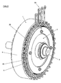
- the partially broken perspective view which shows a rotary electric machine The perspective view of the rotary electric machine except a housing.
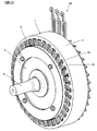
- the perspective view of the rotary electric machine except a housing.
- the perspective view of a stator The perspective view of a stator core.
- (A) is a plan view of the stator coil
- (b) is a front view of the stator coil
- (c) is a bottom view of the stator coil
- (d) is a side view of the stator coil
- (e) is (b) ) Enlarged schematic view of E).
- the cross-sectional schematic diagram of a stator The partial expansion schematic diagram which shows the cross section of the stator coil wound around one tooth.
- (A) is a perspective view which shows the step transition part formed in the 1st linear part
- (b) is the figure which gave the hatching to the part showing a step transition part and a curve corner
- the figure for demonstrating the process of manufacturing a stator coil The figure for demonstrating the process of manufacturing the intermediate product of the stator coil which concerns on a comparative example.
- the partial expansion schematic diagram which shows the cross section of the stator coil wound around one tooth.
- FIG. 1 is a partially broken perspective view showing the rotating electrical machine 100.
- a part of the housing 9 is cut away.
- 2 and 3 are perspective views of the rotating electrical machine 100 with the housing 9 removed.
- FIG. 3 is a perspective view of the rotating electrical machine 100 viewed from the opposite side of FIG.
- the rotating electrical machine 100 can be applied to, for example, a pure electric vehicle that runs only by the rotating electrical machine 100, or a hybrid electric vehicle that is driven by both the engine and the rotating electrical machine 100.
- the rotating electrical machine 100 operates as an electric motor or a generator, and includes a stator (hereinafter referred to as a stator 1) and a rotor that rotates with respect to the stator 1 (hereinafter referred to as a rotor 2). And a housing 9 that accommodates and holds the rotor 2 and the stator 1.
- the rotor 2 is rotatably disposed inside the cylindrical stator 1.
- the rotor 2 includes a cylindrical rotor core (rotor core) and a permanent magnet.
- a cylindrical shaft (rotating shaft) 8 is press-fitted into the hollow portion of the rotor core, and the rotor core is fixed to the shaft 8.
- permanent magnets are arranged at equal intervals along the circumferential direction.
- the housing 9 includes a cylindrical center bracket 9c and a pair of end brackets 9a and 9b attached so as to close the openings at both ends of the center bracket 9c.
- a bearing 11 is provided in each of the end brackets 9a and 9b.
- the stator 1 is held by a center bracket 9c, and the shaft 8 of the rotor 2 is rotatably held by bearings 11 provided on the end brackets 9a and 9b.
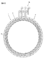
- FIG. 4 is a view of the stator 1 as viewed from the axial direction
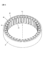
- FIG. 5 is a perspective view of the stator 1.
- the stator 1 includes a cylindrical stator core (stator core) 4 and a stator coil 5 (see FIG. 10) constituting U-phase, V-phase, and W-phase windings. I have.
- the U-phase, V-phase, and W-phase windings are wound around the stator core 4 in a concentrated manner, and a power connection terminal 59 is provided at each end of the U-phase, V-phase, and W-phase windings. Yes.
- the power connection terminal 59 is connected to a power converter (inverter) via a conductive member (not shown). DC power from a battery (not shown) is converted into AC power by a power converter and supplied to each phase winding via a power connection terminal 59, whereby a rotating magnetic field is generated and the rotor 2 rotates.
- FIG. 6 is a perspective view of the stator core 4.
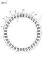
- a plurality of slots 40 and teeth 41 extending in the direction of the central axis CL of the stator core 4 are alternately and circumferentially. They are formed at equal intervals in the direction.
- the stator core 4 is formed, for example, by laminating a plurality of annular core plates formed by punching a magnetic steel sheet having a thickness of about 0.05 to 1.0 mm by press working.
- Each tooth 41 is formed with a constant width in the circumferential direction so as to protrude from the annular core back 43 toward the central axis CL.
- Each tooth 41 serves to guide the rotating magnetic field generated by the supply of AC power to the stator coil 5 to the rotor 2 and to generate rotational torque in the rotor 2.
- the slot 40 is an open slot, and is configured such that a winding portion 50 (see FIG. 10) of a stator coil 5 described later can be inserted from the inner diameter side of the stator core 4.
- the slot 40 is defined by a peripheral wall formed by a circumferential side surface facing each other in a pair of adjacent teeth 41 and an inner peripheral surface of the core back 43.
- FIG. 7 is a perspective view showing the stator core 4 in a state where the insulator 20 is mounted in the slot 40.
- the insulator 20 having a U-shaped cross section is mounted in the slot 40.
- the stator coil 5, which is a concentrated winding coil is mounted in the slot 40 via the insulator 20.
- a drop-off prevention piece 21 having a U-shaped cross section is attached to the opening side of the slot 40.
- the insulator 20 and the drop-off prevention piece 21 are made of an insulating resin material such as polyphenylene sulfide (PPS) or polybutylene terephthalate (PBT).
- PPS polyphenylene sulfide
- PBT polybutylene terephthalate
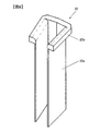
- FIG. 8 is a perspective view showing the insulator 20, and FIG. 9 is a perspective view showing the drop-off prevention piece 21.
- the insulator 20 includes a cover portion 20 a that covers the peripheral wall of the slot 40, and a flange portion 20 b that contacts the axial end surface of the stator core 4 at one longitudinal end of the cover portion 20 a.
- the drop-off prevention piece 21 includes a cover portion 21 a that covers the opening on the inner diameter side of the slot 40, and an insertion portion 21 b that is inserted between the circumferential side surface of the teeth 41 and the cover portion 20 a of the insulator 20. have.
- the insulator 20 and the drop-off prevention piece 21 are attached to the stator core 4, so that the insulation between the stator coil 5 and the stator core 4 is secured by the insulator 20, and the drop-off prevention piece 21 The coil 5 is prevented from falling off to the inner diameter side.
- FIG. 10 is a perspective view showing the stator coil 5.
- the stator coil 5 includes a winding portion 50 in which a conductor 60 is wound around the teeth 41 of the stator 1 one pitch at a time, and a connection terminal portion extending from both ends of the winding portion 50. 52, 53.
- the connection terminal portion 52 of one stator coil 5 is joined to the connection terminal portion 53 of another stator coil 5 (see FIG. 5).
- a plurality of stator coils 5 are joined to form a single phase (U phase, V phase, W phase) winding.
- the conductor 60 constituting the stator coil 5 is a rectangular wire with an insulation coating.
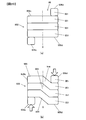
- FIG. 11 is a diagram showing the stator coil 5.
- FIG. 11A is a plan view of the stator coil 5, and
- FIG. 11B is a front view of the stator coil 5.
- FIG. 11C is a bottom view of the stator coil 5, and
- FIG. 11D is a side view of the stator coil 5.
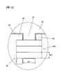
- FIG.11 (e) is the E section enlarged schematic diagram of FIG.11 (b).
- the portions representing the step transition portions 54a, 54b, 54c are hatched
- FIGS. 11 (b) and 11 (e) the portions representing the curved corner portions 55 are hatched.
- the winding part 50 has four unit winding parts 51 (51a, 51b, 51c, 51d).
- Each unit winding portion 51 (51a, 51b, 51c, 51d) includes a pair of first straight portions 56a, 56b, a pair of second straight portions 56c, 56d, a first straight portions 56a, 56b, and a second straight line.
- the unit winding portions 51 each have a rectangular ring shape when viewed from the winding axis X direction.
- the first straight portions 56a and 56b and the second straight portions 56c and 56d indicate conductor portions that are linear when viewed from the winding axis X direction.
- the curved corner portion 55 is a portion that is curved in a range of 90 degrees so that the inner diameter dimension is R1 and the outer diameter dimension is R2 around the point O (R2>). R1).
- the curved corner portion 55 refers to a first linear portion 56a, 56b extending linearly and a second linear portion 56c extending linearly in a plane orthogonal to the winding axis X direction. It refers to a curved conductor portion between 56d.
- FIG. 12 is a schematic cross-sectional view of the stator 1, schematically showing a cross-section cut along a plane orthogonal to the central axis CL of the stator core 4.
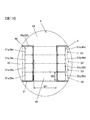
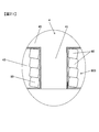
- FIG. 13 is a partially enlarged schematic view showing a cross section of the stator coil 5 wound around one tooth 41, and is an enlarged schematic view of a portion XIII in FIG.
- the insulator 20 is disposed between the stator coil 5 and the teeth 41 to ensure insulation.
- the unit winding portion 51 is disposed so that one side surface of the rectangular conductor 60 is parallel to the side surface of the tooth 41, and one side surface of the conductor 60 is in close contact with the tooth 41 via the cover portion 20 a of the insulator 20. Yes.
- the unit winding portions 51 are also in close contact with each other on the side surfaces of the conductors 60 facing each other.
- the four unit winding portions 51 are attached to the teeth 41.
- the first winding portion 51a, the second winding portion 51b, in order from the outer peripheral side (core back 43 side) to the inner peripheral side (slot opening side) of the slot 40 the third winding part 51c and the fourth winding part 51d are referred to.
- the second straight part 56c and the second straight part 56d constituting the first winding part 51a are arranged to face each other with the teeth 41 interposed therebetween.
- the second straight part 56c and the second straight part 56d constituting each unit winding part 51 serve as the teeth 41. They are placed opposite to each other.
- the second straight portion 56c and the second straight portion 56d of each unit winding portion 51 are arranged such that the distance from the central axis CL of the stator core 4 is the same position.
- the four unit winding portions 51 are arranged in the winding axis X direction.
- the winding portions 50 are arranged in a line and have a multistage structure (laminated structure) in the radial direction of the stator core 4.
- each step in the slot 40 where each conductor 60 is disposed will be described below in order from the outer peripheral side (core back 43 side) of the slot 40 toward the inner peripheral side (slot opening side). They are referred to as the stage (S1), the second stage (S2), the third stage (S3), and the fourth stage (S4).
- the first straight portion 56a is formed on the first straight portion 56a.
- the step transition portion 54a is a skew portion that guides the conductor 60 that has been taken out of the slot from the first step (S1) of one slot 40 to the second step (S2) of another adjacent slot 40. is there.
- the step transition portion 54b is a skew feeding portion that guides the conductor 60 taken out of the slot from the second step (S2) of one slot 40 to the third step (S3) of the other adjacent slot 40. It is.
- the step transition portion 54 c is a skew feeding portion that guides the conductor 60 that has been taken out of the slot from the third step (S 3) of one slot 40 to the fourth step (S 4) of another adjacent slot 40.
- the step transition portions 54a, 54b, and 54c are formed so as to be inclined from a predetermined step toward an adjacent step in a plane orthogonal to the central axis CL of the stator core 4. As shown in FIG. 11A, the step transition portions 54a, 54b, 54c are arranged so as to be slightly shifted in the winding direction of the winding portion 50 so that the adjacent first straight portions 56a are in close contact with each other. Has been.
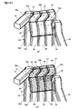
- FIG. 14A is a perspective view showing the step transition portions 54a, 54b, 54c formed in the first straight portion 56a.
- FIG. 14B is a diagram in which hatching is performed on portions representing the step transition portions 54a, 54b, 54c and the curved corner portion 55 in FIG. 14A.
- a part of each step transition portion 54 a, 54 b, 54 c is constituted by a part of the curved corner portion 55.
- One end side of the step transition portion 54a does not overlap with the curved corner portion 55 (see the curved corner portion 55 on the near side in the drawing in FIG. 14B), and between the step transition portion 54a and the curved corner portion 55.
- a non-overlapping region 57 (non-hatched region in the figure) is formed.
- the other end side of the step transition portion 54a overlaps with the curved corner portion 55 (see the curved corner portion 55 on the back side in FIG. 14B), and an overlapping region 58 is formed.
- step transition portion 54b overlaps with the curved corner portion 55 (see the curved corner portion 55 on the near side in FIG. 14B), and an overlapping region 58 is formed.
- the other end side of the step transition portion 54 b does not overlap with the curved corner portion 55 (see the curved corner portion 55 on the back side in FIG. 14B), and between the step transition portion 54 b and the curved corner portion 55. Is formed with a non-overlapping region 57 (non-hatched region in the figure).
- step transition portion 54c overlaps with the curved corner portion 55 (see the curved corner portion 55 on the near side in FIG. 14B), and an overlapping region 58 is formed.
- the other end side of the step transition portion 54 c does not overlap with the curved corner portion 55 (see the curved corner portion 55 on the back side in FIG. 14B), and between the step transition portion 54 c and the curved corner portion 55. Is formed with a non-overlapping region 57 (non-hatched region in the figure).
- stage transition section 54 By configuring the curved corner portion 55 at the end portions of the step transition portions 54a, 54b, 54c, the dimensions of the winding portion 50 in the teeth width direction can be reduced, and the stator coil 5 can be downsized. Can be achieved.
- the stage transition sections 54a, 54b, and 54c are collectively referred to as the stage transition section 54.
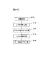
- FIG. 15 is a diagram for explaining a process of manufacturing the rotating electrical machine 100.
- the manufacturing method of the rotating electrical machine 100 includes a preparation step S100, a coil forming step S110, a stator assembling step S120, a coil connecting step S130, and a rotor assembling step S140.
- each component constituting the rotating electrical machine 100 for example, the center bracket 9c, the end brackets 9a and 9b, the stator core 4, the rotor 2, and the like are prepared.
- a permanent magnet is previously mounted on the rotor core of the rotor 2, and the shaft 8 is press-fitted into the hollow portion of the rotor core and integrated.
- the stator coil 5 attached to each tooth 41 is formed (see FIG. 10). Details of the coil forming step S110 will be described later.
- stator assembly step S120 the stator core 4 is fixed to the center bracket 9c by shrink fitting.
- a center bracket 9c that has been heated in advance and expanded in inner diameter by thermal expansion is fitted into the stator core 4.
- the outer periphery of the stator core 4 is tightened by the thermal contraction.
- each stator coil 5 is attached to the teeth 41.
- the winding part 50 is attached to the teeth 41 from the inner diameter side of the stator core 4, the connection terminal part 52 of one stator coil 5 and the connection terminal part 53 of the other stator coil 5 are joined, and each phase (U (Phase, V phase, W phase) windings are formed.
- the insulator 20 is attached to the stator core 4 in advance, and then the stator coil 5 is attached to the teeth 41, and the drop-off prevention piece 21 is attached from the opening side of the slot 40.
- second straight portions 56c and 56d constituting the long-side conductor of the unit winding portion 51 are arranged, and outside the slot 40, the first straight line constituting the short-side conductor of the unit winding portion 51.
- the parts 56a and 56b are arranged.
- the shaft 8 is mounted on the bearing 11 of one end bracket 9a.
- the end bracket 9a is fixed to the center bracket 9c by closing the opening on one end side of the center bracket 9c with one end bracket 9a so that the rotor 2 is arranged inside the stator 1.
- the opening on the other end side of the center bracket 9c is closed with the other end bracket 9b, and the end bracket 9b is fixed to the center bracket 9c.
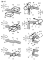
- FIG. 16 is a diagram for explaining a process of manufacturing the stator coil 5.
- a plurality of rectangular ring-shaped unit winding portions 51 are formed by repeatedly bending a single linear conductor 60.
- the skew part 62 which comprises the stage transition part 54a, 54b, 54c is formed by pressing the linear conductor 60 with metal mold
- a curved corner portion 55 including a part of the skew portion 62 is formed.
- a process of forming the skew portion 62 and the curved corner portions 55 before and after the skew portion 62 will be described. That is, the step transition portion 54 formed in the first straight portion 56a shown in FIG. 11, the curved corner portion 55 between the second straight portion 56c and the first straight portion 56a, and the second straight portion 56d. A process of forming the curved corner portion 55 between the first straight portion 56a will be described. It should be noted that the process of forming the curved corner portion 55 between the second straight portion 56c and the first straight portion 56b and the curved corner portion 55 between the second straight portion 56d and the first straight portion 56b are illustrated. Omitted.
- the coil forming step S110 includes a pre-press positioning step S111, a press working step S112, a pre-bending positioning step S114, a bending step S115, a pre-bending positioning step S116, and a bending step S117. Including. For convenience of explanation, as shown in the figure, vertical and longitudinal and lateral directions are defined.
- the straight portion 61 of the conductor (flat wire) 60 is disposed between the mold 70a and the mold 70b.
- the linear portion 61 of the conductor 60 is disposed so as to extend in the front-rear direction. Positioning is performed so that the left and right side surfaces of the rectangular conductor 60 face the pressing surfaces of the left and right molds 70a and 70b, respectively.
- the conductor 60 is supported so as to be movable forward by a feeding device (not shown). The conductor 60 is fed forward by driving the feeding device, and the conductor 60 is positioned at a predetermined position by stopping the feeding device. can do.
- the conductor 60 is clamped from the right and left by the mold 70a and the mold 70b, and the conductor 60 is plastically deformed to form the skewed portion 62.
- the skew portion 62 is curved (bent) at both ends in the left-right direction, forms a predetermined angle with respect to the straight portion 61, and the straight portions 61 before and after the skew portion are 1 pitch. It is formed so as to be shifted by only the left and right width dimensions of the conductor 60.
- the conductor 60 is fed forward by a predetermined amount by the feeding device so that the support rod 72 is positioned near the front end of the skewed portion 62. Perform positioning.
- the conductor 60 is placed on the support rod 72, and the roller 71 is disposed above the conductor 60.
- the support rod 72 and the roller 71 are arranged so that the central axis extends in the left-right direction.
- the roller 71 is configured to be rotatable about the support rod 72 as a rotation center.
- the roller 71 in the bending step S115, the roller 71 is operated so as to wind the conductor 60 around the support rod 72. That is, in the bending step S115, the roller 71 is rotated forward and downward with the support rod 72 as the rotation center, and the roller 71 is pressed against the conductor 60 in front of the skew portion 62. The roller 71 is rotated in consideration of the amount of spring back, and the conductor 60 is bent downward more than 90 degrees to form the curved corner portion 55. Thereby, the stator coil 5 without winding swelling can be formed. After bending the conductor 60, the roller 71 rotates in the opposite direction and returns to the original position.
- the conductor 60 is fed forward by a predetermined amount by the feeding device so that the support rod 72 is positioned near the rear end of the skewed portion 62. Perform positioning.
- the roller 71 in the bending step S117, the roller 71 is operated so that the conductor 60 is wound around the support rod 72. That is, in the bending step S117, the roller 71 is rotated forward and downward with the support rod 72 as the rotation center, and the roller 71 is pressed against the conductor 60 near the rear end of the skew portion 62. Similarly to the bending step S115, the roller 71 is rotated in consideration of the springback amount, and the conductor 60 is bent downward by more than 90 degrees to form the curved corner portion 55 (FIG. 16 (h)). reference). After bending the conductor 60, the roller 71 rotates in the opposite direction and returns to the original position.
- the curved corner 55 between the second straight section 56c and the first straight section 56b and the curved corner 55 between the second straight section 56d and the first straight section 56b are respectively
- the conductor 60 is positioned by a feeding device and is bent by a roller 71 with the support rod 72 as a rotation center. Positioning before bending by the feeding device is performed so that the first straight portions 56a and 56b are shorter than the second straight portions 56c and 56d.
- the coil forming step S110 is repeatedly performed to form a winding portion 50 that is wound a plurality of times, and connection terminal portions 52 and 53 are formed at both ends of the winding portion 50 by a bending process (not shown). .
- stator coil 5 in which a part of the step transition portion 54 (the skew feeding portion 62) is constituted by a part of the curved corner portion 55.
- the stator coil 5 is a stator coil that is attached to the slot 40 of the stator 1 by concentrated winding.
- the stator coil 5 includes a winding part 50 in which the conductor 60 is wound around the teeth 41 of the stator 1 by one pitch, and connection terminal parts 52 and 53 extending from both ends of the winding part 50.
- the winding part 50 has a plurality of rectangular ring-shaped unit winding parts 51. Each unit winding portion 51 has a bending angle connecting the pair of first straight portions 56a, 56b, the pair of second straight portions 56c, 56d, the first straight portions 56a, 56b, and the second straight portions 56c, 56d. Part 55.
- One of the pair of first straight portions 56a and 56b is a step transition portion that shifts the conductor 60 by one pitch in the winding axis X direction.
- 54 (oblique section 62) is formed.
- a part of the step transition part 54 is constituted by a part of the curved corner part 55.
- the teeth width WT the width dimension of the teeth 41
- the conductor width WT the width dimension of the teeth 41
- the first straight portions 56a and 56b are formed shorter than the second straight portions 56c and 56d. That is, the step transition portion 54 is formed not on the long-side second straight portions 56c and 56d arranged in the slot 40 but on the short-side first straight portion 56a arranged outside the slot 40. . Thereby, it is not necessary to enlarge the shape of the slot 40 for the stage shift. Thereby, size reduction of the stator 1 can be achieved.
- the conductor 60 is bent near the both ends of the step transition portion 54 in a direction orthogonal to the virtual plane where the step transition portion 54 exists, and a part of the step transition portion 54 is configured by a part of the curved corner portion 55.
- the curved corner portion 55 is formed so that the step transition portion 54 is positioned on one first straight portion 56a of the pair of first straight portions 56a and 56b.
- the conductors 60 in the slots 40 can be aligned as shown in FIG. That is, the second straight portion 56c and the second straight portion 56d constituting each unit winding portion 51 can be arranged to face each other with the teeth 41 interposed therebetween, and one side surface of the conductor 60 is inserted into the teeth via the insulator 20. 41.
- the heat generated in the conductor 60 is efficiently transmitted to the stator core 4, and the rotating electrical machine 100 with good heat dissipation performance can be provided. Improvement of heat dissipation performance reduces electric resistivity and leads to improvement of motor efficiency.
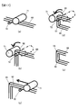
- FIG. 17 is a diagram for explaining a process of manufacturing the intermediate product 90 (see FIG. 18) of the stator coil 905 according to the comparative example.
- FIG. 18 is a diagram illustrating an intermediate product 90 of the stator coil according to the comparative example.
- a plurality of rectangular ring-shaped unit winding portions 951 are formed by repeatedly performing bending, and then pressed against the second linear portions 956c and 956d having a multistage structure as will be described later.
- a step transition portion 954 is formed (see FIG. 20).
- the conductor 60 is positioned (see FIG. 17A) and bent by the roller 71 to form the curved corner portion 55 (see FIG. 17B). Thereafter, the conductor 60 is fed forward by a predetermined amount by the feeding device, positioning is performed (see FIG. 17C), and bending is performed by the roller 71 to form the curved corner portion 55 (FIG. 17D). 17 (e)).
- the intermediate product 90 shown in FIG. 18 is formed by repeatedly performing positioning by the feeding device and bending by the roller 71.
- the conductor 60 is gradually displaced by one pitch over one turn, that is, the conductor 60 is gradually displaced in the winding axis direction by the width of the rectangular conductor 60 during one turn.
- bending is performed to form a winding portion 950 that is wound in a spiral shape.
- FIG. 18 (a) is a plan view of the intermediate product 90
- FIG. 18 (b) is a front view of the intermediate product 90
- FIG. 18 (c) is a side view of the intermediate product 90.
- the conductor 60 is gradually shifted in the winding axis direction in one turn, and a spiral winding portion 950 is formed.
- FIG. 19 is a view showing a state in which the intermediate product 90 is mounted on the teeth 41.
- the intermediate product 90 is attached to the teeth 41 as a finished product of the stator coil, one end of the stator coil extends from the teeth 41 with the same tooth width WT and the same conductor width WC as in the present embodiment. It will stick out.
- the contact area between the core back 43 and the conductor 60 via the insulator 20 is also reduced, the heat dissipation performance may be reduced.
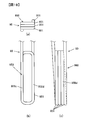
- FIG. 20 is a diagram schematically illustrating a state in which the intermediate product 90 is pressed to form the step transition portion 954.
- 20A is a schematic plan view of the intermediate product 90 before the step transition portion 954 is formed
- FIG. 20B is a schematic plan view showing the stator coil 905 in which the step transition portion 954 is formed. is there.
- the pair of second straight portions 956c and 956d constituting one unit winding portion 951 is a winding axis X. They are not placed facing each other. In other words, the second straight portion 956c and the second straight portion 956d of each unit winding portion 951 are not arranged so that the distance from the central axis of the stator core 4 is the same position.
- the two long-side conductors of the winding part 950 (that is, the bundle of the second straight part 956c and the bundle of the second straight part 956d) are wound. It presses toward the center of the winding part 950 along the axis X direction.
- the stage transition part 954 can be formed.
- the stator coil 905 in which a part of the step transition part 954 is configured by a part of the curved corner part 55 can be formed. Further, since the dimension in the winding axis X direction can be reduced, the stator coil 905 can be accommodated in the slot 40. Therefore, in the comparative example, the same operational effects as the operational effects (1) and (2) of the above-described embodiment are obtained.
- the conductor 60 constituting the second straight portions 956c and 956d is twisted with respect to the side surface of the tooth 41 as shown in FIG. One side surface is inclined, and the adhesion between the conductor 60 and the tooth 41 may be deteriorated. That is, in the comparative example, there is a possibility that the heat dissipation performance is deteriorated.
- one side surface of the conductor 60 is connected to the side surface of the tooth 41 via the covering portion 20a of the insulator 20 as shown in FIG. It is preferable because it can be satisfactorily adhered to.
- the rotary electric machine 100 has been described as an example of the electromagnetic device, but the present invention is not limited to this.
- the present invention can also be applied to an electromagnetic device such as a linear motion electric motor (linear motor) having a linearly extending stator and a movable element operating in a linear direction.
- the electromagnetic device is a device including a rotary or direct acting motor, a generator, and a generator motor.
- the direct-acting stator core corresponds to a cylindrical (annular) stator core 4 shown in FIG.
- a part of the curved corner portion 55 is configured on one end side, and a part of the curved corner portion 55 is not configured on the other end side.
- the present invention is not limited to this.
- Each of the both ends of the step transition portion 54 may constitute a part of the curved corner portion 55.
- a part of the skew part 62 (step transition part 54) may be constituted by a part of the curved corner part 55.
- the present invention is not limited to the above-described embodiments, and other forms conceivable within the scope of the technical idea of the present invention are also included in the scope of the present invention. .
Landscapes
- Engineering & Computer Science (AREA)
- Power Engineering (AREA)
- Manufacturing & Machinery (AREA)
- Manufacture Of Motors, Generators (AREA)
- Windings For Motors And Generators (AREA)
- Insulation, Fastening Of Motor, Generator Windings (AREA)
Abstract
Description
本発明の第2の態様によると、固定子コイルの製造方法は、固定子のティースに導体が1ピッチずつ巻回される巻回部、ならびに、巻回部の両端部から延在する接続端子部を有し、固定子のスロットに集中巻きで装着される固定子コイルを製造する方法であって、巻回部を形成する際、一対の第1直線部と、一対の第2直線部と、第1直線部と第2直線部とを結ぶ湾曲角部とで矩形環形状を呈する単位巻回部を複数形成し、少なくとも一の単位巻回部を形成する際、金型でプレスすることにより導体の直線部を屈曲させて、巻回軸方向に導体を1ピッチずらす斜行部を形成し、斜行部の両端近傍を曲げて、斜行部の一部が湾曲角部の一部で構成されるように、かつ、一対の第1直線部のうちの一方に斜行部が位置するように、湾曲角部を形成する。
-第1の実施の形態-
図1は、回転電機100を示す部分破断斜視図である。図1では、ハウジング9の一部を破断して示している。図2および図3は、ハウジング9を除いた回転電機100の斜視図である。図3は図2の反対側から回転電機100を見た斜視図である。
準備工程S100では、回転電機100を構成する各部品、たとえばセンターブラケット9c、エンドブラケット9a,9b、ステータコア4、ロータ2等を準備する。ロータ2のロータコアには、予め永久磁石が装着され、シャフト8がロータコアの中空部に圧入されて一体となっている。
コイル成形工程S110では、各ティース41に装着される固定子コイル5を成形する(図10参照)。コイル成形工程S110の詳細については後述する。
ステータ組み付け工程S120では、ステータコア4を焼き嵌めによりセンターブラケット9cに固定する。ステータコア4に対して、予め加熱して熱膨張により内径を広げておいたセンターブラケット9cを嵌め込む。センターブラケット9cを冷却して内径を収縮させることで、その熱収縮によりステータコア4の外周部を締め付ける。
コイル接続工程S130では、各固定子コイル5をティース41に装着する。巻回部50をステータコア4の内径側からティース41に装着し、一の固定子コイル5の接続端子部52と、他の固定子コイル5の接続端子部53とを接合し、各相(U相、V相、W相)巻線を形成する。なお、インシュレータ20は、予めステータコア4に装着しておき、その後、固定子コイル5をティース41に装着し、スロット40の開口側から脱落防止片21を装着する。
ロータ組み付け工程S140では、シャフト8を一方のエンドブラケット9aの軸受11に装着する。ロータ2をステータ1の内側に配置させるように、一方のエンドブラケット9aによりセンターブラケット9cの一端側の開口を塞いで、エンドブラケット9aをセンターブラケット9cに固着させる。センターブラケット9cの他端側の開口を他方のエンドブラケット9bによって塞いで、エンドブラケット9bをセンターブラケット9cに固着させる。以上で、回転電機100が完成する。
図16(a)に示すように、プレス前位置決め工程S111では、導体(平角線)60の直線部61を金型70aと金型70bの間に配置する。導体60の直線部61は、前後方向に延在するように配置する。矩形状の導体60の左右両側面がそれぞれ左右の金型70a,70bの押圧面と対向するように、位置決めを行う。なお、導体60は、図示しない送り装置により前方に移動可能に支持されており、送り装置を駆動させることにより導体60を前方に送り、送り装置を停止することで導体60を所定の位置に位置決めすることができる。
図16(b)に示すように、プレス加工工程S112では、金型70aと金型70bにより導体60を左右から挟圧し、導体60を塑性変形させることで斜行部62を形成する。図16(c)に示すように、斜行部62は、両端が左右方向に湾曲(屈曲)され、直線部61に対して所定の角度をなし、斜行部前後の直線部61が1ピッチだけずれるように、すなわち導体60の左右幅寸法分だけずれるように形成されている。
図16(d)に示すように、曲げ前位置決め工程S114では、送り装置により導体60を前方に所定量送って、斜行部62の前端近傍に支持棒72が位置するように、導体60の位置決めを行う。導体60は、支持棒72の上に載置され、ローラ71は導体60の上方に配置されている。支持棒72およびローラ71は、それぞれ中心軸が左右方向に延在するように配置されている。ローラ71は、支持棒72を回動中心として回動可能に構成されている。
図16(e)に示すように、曲げ加工工程S115では、支持棒72に導体60を巻きつけるようにローラ71を動作させる。すなわち、曲げ加工工程S115では、支持棒72を回動中心としてローラ71を前下方に向けて回動させ、斜行部62の前方の導体60にローラ71を押し当てる。スプリングバック量を考慮してローラ71を回動させ、導体60を90度よりも多めに下方向に屈曲させ、湾曲角部55を形成する。これにより、巻き膨らみのない固定子コイル5を形成できる。ローラ71は、導体60を曲げた後、反対方向に回動して元の位置に戻る。
図16(f)に示すように、曲げ前位置決め工程S116では、送り装置により導体60を前方に所定量送って、斜行部62の後端近傍に支持棒72が位置するように、導体60の位置決めを行う。
図16(g)に示すように、曲げ加工工程S117では、支持棒72に導体60を巻きつけるようにローラ71を動作させる。すなわち、曲げ加工工程S117では、支持棒72を回動中心としてローラ71を前下方に向けて回動させ、斜行部62の後端近傍の導体60にローラ71を押し当てる。曲げ加工工程S115と同様に、スプリングバック量を考慮してローラ71を回動させ、導体60を90度よりも多めに下方向に屈曲させ、湾曲角部55を形成する(図16(h)参照)。ローラ71は、導体60を曲げた後、反対方向に回動して元の位置に戻る。
(1)本実施の形態に係る固定子コイル5は、ステータ1のスロット40に集中巻きで装着される固定子コイルである。固定子コイル5は、ステータ1のティース41に導体60が1ピッチずつ巻回される巻回部50と、巻回部50の両端部から延在する接続端子部52,53とを有している。巻回部50は、矩形環形状の単位巻回部51を複数有している。各単位巻回部51は、一対の第1直線部56a,56bと、一対の第2直線部56c,56dと、第1直線部56a,56bと第2直線部56c,56dとを結ぶ湾曲角部55とを有している。一対の第1直線部56a,56bのうちの一方、すなわち接続端子部52,53が配置される側の第1直線部56aには、巻回軸X方向に導体60を1ピッチずらす段移行部54(斜行部62)が形成されている。各単位巻回部51において、段移行部54の一部が湾曲角部55の一部により構成されている。
これにより、巻回部50のティース幅方向の寸法を小さくすることができるので、従来に比べて、固定子コイル5、ステータ1および回転電機100の小型化を図ることができる。
(変形例1)
上述した実施の形態では、電磁装置の一例として、回転電機100について説明したが、本発明はこれに限定されない。直線状に延在する固定子と、直線方向に動作する可動子を備えた直動式の電動機(リニアモータ)等の電磁装置にも本発明を適用できる。つまり、電磁装置とは、回転式、直動式の電動機、発電機および発電電動機を含む装置である。なお、直動式のステータコアは、図6に示す円筒状(円環状)のステータコア4を切り開いて展開したものに相当する。
上述した実施の形態では、矩形断面を有する導体(平角線)を用いた例について説明したが、本発明はこれに限定されない。円形断面を有する導体(丸線)を用いて固定子コイル5を形成した場合についても、固定子コイル5の小型化を図ることができる。なお、平角線を採用することで、スロット40の断面積に対する導体60の断面積(すなわち導体60の占積率)を増やすことができ、回転電機100の銅損を低減できるため、好適である。つまり、平角線を採用することで、回転電機100の小型化、高効率化を図ることができる。
上述した実施の形態では、ロータ2がステータ1の径方向内側に配置されたインナーロータ型の回転電機100について説明したが、ロータ2がステータ1の径方向外側に配置されたアウターロータ型の回転電機に本発明を適用してもよい。
上述した実施の形態では、固定子コイルの層数が1層である例について説明したが、本発明はこれに限定されない。ステータコア4の周方向に多層構造を有する固定子コイルに本発明を適用してもよい。
上述した実施の形態では、固定子コイルの段数が4段である例について説明したが、本発明はこれに限定されない。3段以下であってもよいし、5段以上であってもよい。
上述した実施の形態では、固定子コイルの接続端子部52,53が配置される側の第1直線部56aに段移行部54を設ける例について説明したが、本発明はこれに限定されない。第1直線部56bに段移行部54を設けてもよい。
上述した実施の形態では、一の斜行部62(段移行部54)において、一端側で湾曲角部55の一部を構成し、他端側で湾曲角部55の一部を構成しない例について説明したが、本発明はこれに限定されない。段移行部54の両端のそれぞれで、湾曲角部55の一部を構成してもよい。また、少なくとも一つの単位巻回部51において、斜行部62(段移行部54)の一部が湾曲角部55の一部により構成されていればよい。
日本国特許出願2014年第140466号(2014年7月8日出願)
Claims (11)
- 固定子のスロットに集中巻きで装着される固定子コイルであって、
前記固定子のティースに導体が1ピッチずつ巻回される巻回部と、前記巻回部の両端部から延在する接続端子部とを有し、
前記巻回部は、矩形環形状の単位巻回部を複数有し、
前記単位巻回部は、一対の第1直線部と、一対の第2直線部と、前記第1直線部と前記第2直線部とを結ぶ湾曲角部とを有し、
前記一対の第1直線部のうちの一方には、巻回軸方向に前記導体を1ピッチずらす斜行部が形成され、
少なくとも一の前記単位巻回部において、前記斜行部の一部が前記湾曲角部の一部により構成されている固定子コイル。 - 請求項1に記載の固定子コイルにおいて、
前記第1直線部は前記第2直線部よりも短い固定子コイル。 - 請求項1または2に記載の固定子コイルと、
前記固定子コイルが集中巻きで装着される固定子鉄心とを備えている固定子。 - 請求項3に記載の固定子において、
前記第2直線部は前記スロット内に配置され、
前記第1直線部は前記スロット外に配置されている固定子。 - 請求項3に記載の固定子と、前記固定子に対して可動する可動子とを備えている電磁装置。
- 固定子のティースに導体が1ピッチずつ巻回される巻回部、ならびに、前記巻回部の両端部から延在する接続端子部を有し、前記固定子のスロットに集中巻きで装着される固定子コイルを製造する方法であって、
前記巻回部を形成する際、一対の第1直線部と、一対の第2直線部と、前記第1直線部と前記第2直線部とを結ぶ湾曲角部とで矩形環形状を呈する単位巻回部を複数形成し、
少なくとも一の前記単位巻回部を形成する際、
金型でプレスすることにより導体の直線部を屈曲させて、巻回軸方向に前記導体を1ピッチずらす斜行部を形成し、
前記斜行部の両端近傍を曲げて、前記斜行部の一部が前記湾曲角部の一部で構成されるように、かつ、前記一対の第1直線部のうちの一方に前記斜行部が位置するように、前記湾曲角部を形成する固定子コイルの製造方法。 - 請求項6に記載の固定子コイルの製造方法において、
前記第1直線部が前記第2直線部よりも短くなるように前記湾曲角部を形成する固定子コイルの製造方法。 - 請求項6または7に記載の固定子コイルの製造方法により製造された固定子コイル。
- 請求項8に記載の固定子コイルが集中巻きで固定子鉄心に装着された固定子。
- 請求項9に記載の固定子において、
前記第2直線部は前記スロット内に配置され、
前記第1直線部は前記スロット外に配置されている固定子。 - 請求項9に記載の固定子と、前記固定子に対して可動する可動子とを備えている電磁装置。
Priority Applications (3)
| Application Number | Priority Date | Filing Date | Title |
|---|---|---|---|
| CN201580024471.9A CN106464059B (zh) | 2014-07-08 | 2015-04-30 | 定子线圈、定子、电磁装置及定子线圈的制造方法 |
| US15/315,737 US10547223B2 (en) | 2014-07-08 | 2015-04-30 | Stator coil, stator, electromagnetic device, and method of manufacturing stator coil |
| JP2016532473A JP6298161B2 (ja) | 2014-07-08 | 2015-04-30 | 固定子コイル、固定子、電磁装置、ならびに、固定子コイルの製造方法 |
Applications Claiming Priority (2)
| Application Number | Priority Date | Filing Date | Title |
|---|---|---|---|
| JP2014-140466 | 2014-07-08 | ||
| JP2014140466 | 2014-07-08 |
Publications (1)
| Publication Number | Publication Date |
|---|---|
| WO2016006310A1 true WO2016006310A1 (ja) | 2016-01-14 |
Family
ID=55063955
Family Applications (1)
| Application Number | Title | Priority Date | Filing Date |
|---|---|---|---|
| PCT/JP2015/062964 Ceased WO2016006310A1 (ja) | 2014-07-08 | 2015-04-30 | 固定子コイル、固定子、電磁装置、ならびに、固定子コイルの製造方法 |
Country Status (4)
| Country | Link |
|---|---|
| US (1) | US10547223B2 (ja) |
| JP (1) | JP6298161B2 (ja) |
| CN (1) | CN106464059B (ja) |
| WO (1) | WO2016006310A1 (ja) |
Cited By (4)
| Publication number | Priority date | Publication date | Assignee | Title |
|---|---|---|---|---|
| JP2017131046A (ja) * | 2016-01-21 | 2017-07-27 | 株式会社明電舎 | コイル及びこれを用いた回転電機の固定子 |
| CN110476326A (zh) * | 2017-04-13 | 2019-11-19 | 松下知识产权经营株式会社 | 线圈和使用该线圈的马达 |
| JP2021090304A (ja) * | 2019-12-05 | 2021-06-10 | 株式会社デンソー | 回転電機 |
| EP3200323B1 (en) * | 2016-01-27 | 2022-03-16 | Regal Beloit America, Inc. | Motor for use in refrigerant environment |
Families Citing this family (10)
| Publication number | Priority date | Publication date | Assignee | Title |
|---|---|---|---|---|
| WO2016051978A1 (ja) * | 2014-09-29 | 2016-04-07 | 日立オートモティブシステムズ株式会社 | 回転電機の固定子、及びこれを備えた回転電機 |
| WO2018003461A1 (ja) * | 2016-06-30 | 2018-01-04 | 日立オートモティブシステムズ株式会社 | 回転電機 |
| EP3614535A4 (en) * | 2017-04-19 | 2020-11-25 | LG Electronics Inc. -1- | ROTATING ELECTRICAL DEVICE STATOR |
| CN111277065A (zh) * | 2018-12-04 | 2020-06-12 | 联合汽车电子有限公司 | 一种定子绕组的端部连接结构及同轴式永磁同步电机 |
| US11146137B2 (en) * | 2019-06-03 | 2021-10-12 | Hiwin Mikrosystem Corp. | Coil insulation structure for rotating machine |
| CN113872362B (zh) * | 2021-09-30 | 2023-05-02 | 厦门势拓御能科技有限公司 | 一种新型扁线及定子组件、制造方法、扁线电机 |
| DE102021125495A1 (de) * | 2021-10-01 | 2023-04-06 | Bayerische Motoren Werke Aktiengesellschaft | Verfahren zum Herstellen einer ein- oder mehrfachen Lagenspule, Lagenspule, elektrische Maschine sowie Vorrichtung |
| US20230163652A1 (en) * | 2021-11-19 | 2023-05-25 | Ford Global Technologies, Llc | Stator core with cuffed slot liner |
| WO2024246954A1 (en) * | 2023-06-02 | 2024-12-05 | India Nippon Electricals Ltd | Conductor assembly stator for permanent magnet energy conversion device |
| CN117375285A (zh) * | 2023-10-11 | 2024-01-09 | 浙江盘毂动力科技有限公司 | 一种定子线圈及定子组件 |
Citations (4)
| Publication number | Priority date | Publication date | Assignee | Title |
|---|---|---|---|---|
| JP2005318669A (ja) * | 2004-04-27 | 2005-11-10 | Honda Motor Co Ltd | ステータ |
| JP2008178199A (ja) * | 2007-01-17 | 2008-07-31 | Toyota Motor Corp | コイル製造方法、モータのコイル、及びモータの固定子 |
| JP2008199719A (ja) * | 2007-02-09 | 2008-08-28 | Denso Corp | 回転電機及び界磁コイルの製造方法 |
| WO2011001736A1 (ja) * | 2009-06-29 | 2011-01-06 | トヨタ自動車株式会社 | 多層巻きコイル、ステータ、及びその製造方法 |
Family Cites Families (11)
| Publication number | Priority date | Publication date | Assignee | Title |
|---|---|---|---|---|
| US5365135A (en) * | 1993-11-12 | 1994-11-15 | Westinghouse Electric Corporation | Generator slot hose wedge assembly |
| SE510925C2 (sv) * | 1997-11-26 | 1999-07-12 | Asea Brown Boveri | Elektromagnetisk anordning |
| TW470816B (en) * | 2000-09-29 | 2002-01-01 | Delta Electronics Inc | Method of simultaneously forming a bobbin and a silicon steel plate of a rotating device |
| US6555942B1 (en) * | 2002-05-10 | 2003-04-29 | Chun-Pu Hsu | Assembly type stator structure having flat wire wound coils |
| DE102007041866A1 (de) * | 2007-01-31 | 2008-08-14 | Denso Corp., Kariya | Elektrische rotierende Maschine mit einem Wicklungsteil und Verfahren zur Herstellung des Wicklungsteiles |
| JP4506895B2 (ja) * | 2008-04-07 | 2010-07-21 | 株式会社デンソー | 波巻きステータコイルの製造方法 |
| US8427024B2 (en) * | 2009-12-18 | 2013-04-23 | Toyota Jidosha Kabushiki Kaisha | Stator |
| JP5907650B2 (ja) | 2010-04-28 | 2016-04-26 | 日産自動車株式会社 | ステータおよびステータの巻線引き出し方法 |
| US20110266912A1 (en) * | 2010-04-30 | 2011-11-03 | Alstom Hydro France | Rotating electric machine with a stator winding comprising a plurality of coils and method for manufacturing same |
| JP5004110B2 (ja) * | 2010-07-30 | 2012-08-22 | 本田技研工業株式会社 | アウターロータ型突極集中巻き電動機 |
| US9712024B2 (en) * | 2012-07-25 | 2017-07-18 | Aisin Aw Co., Ltd. | Coil end shaping apparatus and method |
-
2015
- 2015-04-30 CN CN201580024471.9A patent/CN106464059B/zh active Active
- 2015-04-30 JP JP2016532473A patent/JP6298161B2/ja active Active
- 2015-04-30 WO PCT/JP2015/062964 patent/WO2016006310A1/ja not_active Ceased
- 2015-04-30 US US15/315,737 patent/US10547223B2/en active Active
Patent Citations (4)
| Publication number | Priority date | Publication date | Assignee | Title |
|---|---|---|---|---|
| JP2005318669A (ja) * | 2004-04-27 | 2005-11-10 | Honda Motor Co Ltd | ステータ |
| JP2008178199A (ja) * | 2007-01-17 | 2008-07-31 | Toyota Motor Corp | コイル製造方法、モータのコイル、及びモータの固定子 |
| JP2008199719A (ja) * | 2007-02-09 | 2008-08-28 | Denso Corp | 回転電機及び界磁コイルの製造方法 |
| WO2011001736A1 (ja) * | 2009-06-29 | 2011-01-06 | トヨタ自動車株式会社 | 多層巻きコイル、ステータ、及びその製造方法 |
Cited By (10)
| Publication number | Priority date | Publication date | Assignee | Title |
|---|---|---|---|---|
| JP2017131046A (ja) * | 2016-01-21 | 2017-07-27 | 株式会社明電舎 | コイル及びこれを用いた回転電機の固定子 |
| EP3200323B1 (en) * | 2016-01-27 | 2022-03-16 | Regal Beloit America, Inc. | Motor for use in refrigerant environment |
| CN110476326A (zh) * | 2017-04-13 | 2019-11-19 | 松下知识产权经营株式会社 | 线圈和使用该线圈的马达 |
| JPWO2018189979A1 (ja) * | 2017-04-13 | 2020-02-27 | パナソニックIpマネジメント株式会社 | コイル及びそれを用いたモータ |
| EP3611826A4 (en) * | 2017-04-13 | 2020-04-22 | Panasonic Intellectual Property Management Co., Ltd. | Coil and motor using same |
| US10965198B2 (en) | 2017-04-13 | 2021-03-30 | Panasonic Intellectual Property Management Co., Ltd. | Coil and motor using same |
| JP7122505B2 (ja) | 2017-04-13 | 2022-08-22 | パナソニックIpマネジメント株式会社 | コイル及びそれを用いたモータ |
| JP2021090304A (ja) * | 2019-12-05 | 2021-06-10 | 株式会社デンソー | 回転電機 |
| US20220302790A1 (en) * | 2019-12-05 | 2022-09-22 | Denso Corporation | Rotating electrical machine |
| JP7463707B2 (ja) | 2019-12-05 | 2024-04-09 | 株式会社デンソー | 回転電機 |
Also Published As
| Publication number | Publication date |
|---|---|
| CN106464059B (zh) | 2018-10-23 |
| CN106464059A (zh) | 2017-02-22 |
| JPWO2016006310A1 (ja) | 2017-04-27 |
| JP6298161B2 (ja) | 2018-03-20 |
| US20170117767A1 (en) | 2017-04-27 |
| US10547223B2 (en) | 2020-01-28 |
Similar Documents
| Publication | Publication Date | Title |
|---|---|---|
| JP6298161B2 (ja) | 固定子コイル、固定子、電磁装置、ならびに、固定子コイルの製造方法 | |
| JP7142700B2 (ja) | 分布巻ラジアルギャップ型回転電機及びその固定子 | |
| JP6267907B2 (ja) | バスバーユニットおよびブラシレスモータ | |
| JP5635470B2 (ja) | 回転電機および回転電機の製造方法 | |
| CN106663997A (zh) | 定子制造方法以及定子 | |
| WO2008020471A1 (en) | Rotating electric machine | |
| US11018543B2 (en) | Method for manufacturing stator of rotary electric machine including a cassette coil | |
| JP2017131046A (ja) | コイル及びこれを用いた回転電機の固定子 | |
| JP4502041B2 (ja) | 回転電機の固定子およびその製造方法 | |
| WO2020174817A1 (ja) | 回転電機のステータ、回転電機、回転電機のステータの製造方法、および、回転電機の製造方法 | |
| JP6065436B2 (ja) | 電動モータ | |
| WO2012169059A1 (ja) | 回転電機の固定子、回転電機の固定子の製造方法、及び回転電機 | |
| US20190393740A1 (en) | Stator and rotary electric machine | |
| JP2011135733A (ja) | 回転電機 | |
| JP6498536B2 (ja) | コアおよび回転電機 | |
| CN106411014B (zh) | 旋转电机及其制造方法、定子线圈、线圈树脂结构体 | |
| JP7254140B1 (ja) | 回転電機 | |
| US20180115211A1 (en) | Rotary electric machine | |
| CN103683555A (zh) | 定子和旋转电机 | |
| JP7380997B2 (ja) | コイル及び回転機 | |
| WO2022264494A1 (ja) | 回転電機および回転電機の製造方法 | |
| WO2018168108A1 (ja) | 回転電機 | |
| JP2011229290A (ja) | モータ | |
| JP2025090990A (ja) | 回転電機のステータコア | |
| JP2019115173A (ja) | ステータ |
Legal Events
| Date | Code | Title | Description |
|---|---|---|---|
| 121 | Ep: the epo has been informed by wipo that ep was designated in this application |
Ref document number: 15819407 Country of ref document: EP Kind code of ref document: A1 |
|
| ENP | Entry into the national phase |
Ref document number: 2016532473 Country of ref document: JP Kind code of ref document: A |
|
| WWE | Wipo information: entry into national phase |
Ref document number: 15315737 Country of ref document: US |
|
| NENP | Non-entry into the national phase |
Ref country code: DE |
|
| 122 | Ep: pct application non-entry in european phase |
Ref document number: 15819407 Country of ref document: EP Kind code of ref document: A1 |