JP7380997B2 - コイル及び回転機 - Google Patents
コイル及び回転機 Download PDFInfo
- Publication number
- JP7380997B2 JP7380997B2 JP2023514847A JP2023514847A JP7380997B2 JP 7380997 B2 JP7380997 B2 JP 7380997B2 JP 2023514847 A JP2023514847 A JP 2023514847A JP 2023514847 A JP2023514847 A JP 2023514847A JP 7380997 B2 JP7380997 B2 JP 7380997B2
- Authority
- JP
- Japan
- Prior art keywords
- coil
- outer circumferential
- circumferential surface
- coil layer
- corner
- Prior art date
- Legal status (The legal status is an assumption and is not a legal conclusion. Google has not performed a legal analysis and makes no representation as to the accuracy of the status listed.)
- Active
Links
Images


Classifications
-
- H—ELECTRICITY
- H02—GENERATION; CONVERSION OR DISTRIBUTION OF ELECTRIC POWER
- H02K—DYNAMO-ELECTRIC MACHINES
- H02K1/00—Details of the magnetic circuit
- H02K1/06—Details of the magnetic circuit characterised by the shape, form or construction
- H02K1/12—Stationary parts of the magnetic circuit
- H02K1/16—Stator cores with slots for windings
-
- H—ELECTRICITY
- H02—GENERATION; CONVERSION OR DISTRIBUTION OF ELECTRIC POWER
- H02K—DYNAMO-ELECTRIC MACHINES
- H02K15/00—Processes or apparatus specially adapted for manufacturing, assembling, maintaining or repairing of dynamo-electric machines
- H02K15/04—Processes or apparatus specially adapted for manufacturing, assembling, maintaining or repairing of dynamo-electric machines of windings prior to their mounting into the machines
- H02K15/043—Processes or apparatus specially adapted for manufacturing, assembling, maintaining or repairing of dynamo-electric machines of windings prior to their mounting into the machines winding flat conductive wires or sheets
- H02K15/0431—Concentrated windings
-
- H—ELECTRICITY
- H02—GENERATION; CONVERSION OR DISTRIBUTION OF ELECTRIC POWER
- H02K—DYNAMO-ELECTRIC MACHINES
- H02K3/00—Details of windings
- H02K3/04—Windings characterised by the conductor shape, form or construction, e.g. with bar conductors
- H02K3/18—Windings for salient poles
-
- H—ELECTRICITY
- H02—GENERATION; CONVERSION OR DISTRIBUTION OF ELECTRIC POWER
- H02K—DYNAMO-ELECTRIC MACHINES
- H02K3/00—Details of windings
- H02K3/04—Windings characterised by the conductor shape, form or construction, e.g. with bar conductors
- H02K3/28—Layout of windings or of connections between windings
-
- H—ELECTRICITY
- H02—GENERATION; CONVERSION OR DISTRIBUTION OF ELECTRIC POWER
- H02K—DYNAMO-ELECTRIC MACHINES
- H02K3/00—Details of windings
- H02K3/46—Fastening of windings on the stator or rotor structure
- H02K3/52—Fastening salient pole windings or connections thereto
- H02K3/521—Fastening salient pole windings or connections thereto applicable to stators only
- H02K3/522—Fastening salient pole windings or connections thereto applicable to stators only for generally annular cores with salient poles
-
- H—ELECTRICITY
- H02—GENERATION; CONVERSION OR DISTRIBUTION OF ELECTRIC POWER
- H02K—DYNAMO-ELECTRIC MACHINES
- H02K1/00—Details of the magnetic circuit
- H02K1/06—Details of the magnetic circuit characterised by the shape, form or construction
- H02K1/12—Stationary parts of the magnetic circuit
- H02K1/14—Stator cores with salient poles
Landscapes
- Engineering & Computer Science (AREA)
- Power Engineering (AREA)
- Manufacturing & Machinery (AREA)
- Windings For Motors And Generators (AREA)
Description
回転機としてのモータ10について、図1~5を参照して説明する。モータ10は、各種の製品に搭載される。例えば、モータ10は、電動車両の駆動源として利用される。電動車両の例としては、電気自動車、電動自転車、電動車椅子、電動カート及び電動配膳車が挙げられる。電気自動車は、ハイブリッド自動車を含む。モータ10は、ロータ20と、ステータ30とを備える(図1,2参照)。実施形態は、モータ10として内転型のブラシレスモータを例示する。
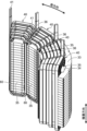
コイル構造について図1~4,6を参照して説明する。コイル40は、複数のコイル層50を含む。実施形態では、コイル40は、6個のコイル層50を含む(図3,6参照)。コイル40に設けるコイル層50の数は、2個以上5個以下としてもよく、又は7個以上としてもよい。コイル40のコイル層50の数は、諸条件を考慮して適宜決定される。実施形態では、6個のコイル層50を「コイル層51,52,53,54,55,56」という。コイル層51,52,53,54,55,56を区別しない場合又はこれらを総称する場合、「コイル層50」という。
コイル構造が採用する千鳥構造について、図3,6及び図8上段を参照して説明する。但し、この説明は、第二方向に接するコイル層51,52を対象とする。コイル40では、コイル層52,53、コイル層53,54、コイル層54,55及びコイル層55,56は、コイル層51,52と同様、第二方向に接する。説明は省略するが、コイル層52,53、コイル層53,54、コイル層54,55及びコイル層55,56でも、コイル層51,52と同様の構造が実現される。
実施形態によれば、次のような効果を得ることができる。
実施形態は、次のようにすることもできる。以下に示す変形例のうちの幾つかの構成は、適宜組み合わせて採用することもできる。以下では、上記とは異なる点を説明することとし、同様の点についての説明は適宜省略する。
22 シャフト、 30 ステータ、 31 ステータコア
32 ヨーク、 33 ヨーク片、 34 装着溝、 35 ティース
36 スロット、 40,40U,40V,40W コイル
41,41U,41V,41W 引出線
42,42U,42V,42W コイルユニット
43,43U,43V,43W 接続端子
44 第一連結導体、 45 第二連結導体
50,51,52,53,54,55,56 コイル層
60 絶縁部材、 70 コイル
71,72,73,74,75,76 コイル層
A 第一部分、 B 第二部分、 C 第三部分、 D 第四部分
E1 第一軸部分、 E2 第二軸部分、 S 隙間
Claims (4)
- 平角導体を渦巻き状に巻回させた第一コイル層と、
前記平角導体によって前記第一コイル層と繋がり、前記平角導体を渦巻き状に巻回させた第二コイル層と、を含み、
前記第二コイル層は、前記第二コイル層の前記第一コイル層及び前記第二コイル層で前記平角導体が重なり合う放射状の第一方向に直交する第二方向の第一側の第一側面で前記第一コイル層の前記第二方向の第二側の第二側面と接し、
前記第一コイル層は、
第一部分と、
前記第一部分と連続し且つ内周面で前記第一部分の外周面と接する第二部分と、を含み、
前記第一部分の前記第一方向としての第一軸方向に沿った第一軸部分と前記第一部分の前記第一軸方向に直交する前記第一方向としての第二軸方向に沿った第二軸部分とを繋ぐ前記第一部分の角部は、前記第一方向の内周側の辺が前記第一方向の外周側の辺より長い台形状の断面形状を有し、
前記第二部分の前記第一軸方向に沿った第一軸部分と前記第二部分の前記第二軸方向に沿った第二軸部分とを繋ぐ前記第二部分の角部は、前記第一方向の内周側の辺が前記第一方向の外周側の辺より長い台形状の断面形状を有し、
前記第二コイル層は、
第三部分と、
前記第三部分と連続し且つ内周面で前記第三部分の外周面と接する第四部分と、を含み、
前記第三部分の前記第一軸方向に沿った第一軸部分と前記第三部分の前記第二軸方向に沿った第二軸部分とを繋ぐ前記第三部分の角部は、前記第一方向の内周側の辺が前記第一方向の外周側の辺より長い台形状の断面形状を有し、
前記第四部分の前記第一軸方向に沿った第一軸部分と前記第四部分の前記第二軸方向に沿った第二軸部分とを繋ぐ前記第四部分の角部は、前記第一方向の内周側の辺が前記第一方向の外周側の辺より長い台形状の断面形状を有し、
前記第三部分は、前記第一側面と前記第二側面とが接した接触状態で、前記第一部分及び前記第二部分と前記第二方向に隣り合い、
前記第四部分は、前記接触状態で、前記第一部分と前記第二方向に隣り合わずに前記第二部分と前記第二方向に隣り合い、
前記第三部分の外周面は、前記接触状態で、前記第一部分の外周面より前記第一方向の外周側で且つ前記第二部分の外周面より前記第一方向の内周側に配置され、
前記第四部分の外周面は、前記接触状態で、前記第二部分の外周面より前記第一方向の外周側に配置され、
前記第二部分の角部の前記第一方向の内周側は、前記第四部分の角部の内周面と、前記第一方向の外周側から内周側に向かって前記第二方向の第二側から第一側に傾斜した前記第三部分の角部の前記第二方向の第一側の傾斜面と、によって囲まれた領域に配置され、
前記第三部分の角部の前記第一方向の内周側は、前記第二部分の角部の内周面と、前記第一方向の外周側から内周側に向かって前記第二方向の第一側から第二側に傾斜した前記第一部分の角部の前記第二方向の第二側の傾斜面と、によって囲まれた領域に配置される、コイル。 - 前記第三部分の外周面は、前記接触状態で、前記第一部分の外周面より前記第一軸方向の外周側で且つ前記第二部分の外周面より前記第一軸方向の内周側に配置され、
前記第四部分の外周面は、前記接触状態で、前記第二部分の外周面より前記第一軸方向の外周側に配置される、請求項1に記載のコイル。 - 前記第三部分の外周面は、前記接触状態で、前記第一部分の外周面より前記第二軸方向の外周側で且つ前記第二部分の外周面より前記第二軸方向の内周側に配置され、
前記第四部分の外周面は、前記接触状態で、前記第二部分の外周面より前記第二軸方向の外周側に配置される、請求項2に記載のコイル。 - ロータと、
ステータと、を備え、
前記ステータは、
請求項1から請求項3の何れか1項に記載のコイルと、
鋼板を積層して形成され、ヨークと、前記ヨークから前記ロータの側に向かって前記第二方向に突出するティースと、を含むステータコアと、を備え、
前記コイルは、前記ティースに設けられる、回転機。
Applications Claiming Priority (3)
| Application Number | Priority Date | Filing Date | Title |
|---|---|---|---|
| JP2021081283 | 2021-05-12 | ||
| JP2021081283 | 2021-05-12 | ||
| PCT/JP2022/016022 WO2022239561A1 (ja) | 2021-05-12 | 2022-03-30 | コイル及び回転機 |
Publications (2)
| Publication Number | Publication Date |
|---|---|
| JPWO2022239561A1 JPWO2022239561A1 (ja) | 2022-11-17 |
| JP7380997B2 true JP7380997B2 (ja) | 2023-11-15 |
Family
ID=84028251
Family Applications (1)
| Application Number | Title | Priority Date | Filing Date |
|---|---|---|---|
| JP2023514847A Active JP7380997B2 (ja) | 2021-05-12 | 2022-03-30 | コイル及び回転機 |
Country Status (4)
| Country | Link |
|---|---|
| US (1) | US12567777B2 (ja) |
| EP (1) | EP4340183A4 (ja) |
| JP (1) | JP7380997B2 (ja) |
| WO (1) | WO2022239561A1 (ja) |
Families Citing this family (1)
| Publication number | Priority date | Publication date | Assignee | Title |
|---|---|---|---|---|
| JP7504202B2 (ja) * | 2020-05-14 | 2024-06-21 | 東芝産業機器システム株式会社 | インシュレータ、固定子、及び回転電機 |
Citations (2)
| Publication number | Priority date | Publication date | Assignee | Title |
|---|---|---|---|---|
| JP2005304244A (ja) | 2004-04-15 | 2005-10-27 | Toyota Motor Corp | 回転電機のコイル、回転電機およびコイルの製造方法 |
| WO2014068695A1 (ja) | 2012-10-31 | 2014-05-08 | 三菱電機株式会社 | 回転電機のコイルおよび回転電機 |
Family Cites Families (6)
| Publication number | Priority date | Publication date | Assignee | Title |
|---|---|---|---|---|
| JP5386265B2 (ja) * | 2009-08-05 | 2014-01-15 | 日立オートモティブシステムズ株式会社 | 回転電機および車両 |
| JP5555933B2 (ja) | 2012-11-02 | 2014-07-23 | 福井県 | 巻線の製造方法及び製造装置 |
| JP5499349B2 (ja) | 2012-11-02 | 2014-05-21 | 福井県 | 巻線構造及びそれを用いた電気機器 |
| JP6276041B2 (ja) * | 2014-01-21 | 2018-02-07 | トヨタ自動車株式会社 | 回転電機ステータ |
| JP5768305B1 (ja) | 2014-09-19 | 2015-08-26 | 福井県 | 固定子の製造方法および装置 |
| FI20186094A1 (en) * | 2018-12-17 | 2020-06-18 | Lappeenrannan Teknillinen Yliopisto | Tangle for a winding in an electric machine |
-
2022
- 2022-03-30 WO PCT/JP2022/016022 patent/WO2022239561A1/ja not_active Ceased
- 2022-03-30 JP JP2023514847A patent/JP7380997B2/ja active Active
- 2022-03-30 US US18/290,060 patent/US12567777B2/en active Active
- 2022-03-30 EP EP22807265.8A patent/EP4340183A4/en active Pending
Patent Citations (2)
| Publication number | Priority date | Publication date | Assignee | Title |
|---|---|---|---|---|
| JP2005304244A (ja) | 2004-04-15 | 2005-10-27 | Toyota Motor Corp | 回転電機のコイル、回転電機およびコイルの製造方法 |
| WO2014068695A1 (ja) | 2012-10-31 | 2014-05-08 | 三菱電機株式会社 | 回転電機のコイルおよび回転電機 |
Also Published As
| Publication number | Publication date |
|---|---|
| US12567777B2 (en) | 2026-03-03 |
| EP4340183A1 (en) | 2024-03-20 |
| EP4340183A4 (en) | 2025-05-07 |
| US20240243633A1 (en) | 2024-07-18 |
| JPWO2022239561A1 (ja) | 2022-11-17 |
| WO2022239561A1 (ja) | 2022-11-17 |
Similar Documents
| Publication | Publication Date | Title |
|---|---|---|
| USRE46265E1 (en) | Rotating electric apparatus and method for connecting stator coils thereof | |
| CN105210267B (zh) | 旋转电机及其制造方法 | |
| CN106464059B (zh) | 定子线圈、定子、电磁装置及定子线圈的制造方法 | |
| US8779643B2 (en) | Stator for electric rotating machine and method of manufacturing same | |
| CN104584391B (zh) | 旋转电机及其制造方法 | |
| JP5472057B2 (ja) | 固定子巻線の巻回方法,固定子巻線の巻回装置及び固定子巻線の製造装置 | |
| US8203247B2 (en) | Stator for electric rotating machine | |
| KR20120041127A (ko) | 고정자, 브러시리스 모터 및 이의 제조방법 | |
| CN110445268B (zh) | 用于旋转电机的定子 | |
| US20100148621A1 (en) | Stator for electric rotating machine | |
| JP6165260B2 (ja) | 回転電機 | |
| JP2016152752A (ja) | 回転電機の固定子 | |
| JP2010136537A (ja) | 回転電機およびその製造方法 | |
| CN104716765A (zh) | 旋转电机 | |
| JP6065436B2 (ja) | 電動モータ | |
| US8659201B2 (en) | Stator for electric rotating machine | |
| CN106464054A (zh) | 旋转电机及其制造方法 | |
| JP2012095488A (ja) | 回転電機用ロータ、およびこれを用いた回転電機 | |
| JP7380997B2 (ja) | コイル及び回転機 | |
| JP7836539B2 (ja) | 回転機及び直列コイル群 | |
| JP6331978B2 (ja) | 固定子巻線の製造方法 | |
| JP6968215B2 (ja) | 回転電機 | |
| JP2011160572A (ja) | 回転電機のステータの製造方法 | |
| US12463474B2 (en) | Stator for rotating electrical machine and method for manufacturing stator for rotating electrical machine | |
| JP7790037B2 (ja) | モータ |
Legal Events
| Date | Code | Title | Description |
|---|---|---|---|
| A621 | Written request for application examination |
Free format text: JAPANESE INTERMEDIATE CODE: A621 Effective date: 20230302 |
|
| A871 | Explanation of circumstances concerning accelerated examination |
Free format text: JAPANESE INTERMEDIATE CODE: A871 Effective date: 20230302 |
|
| A131 | Notification of reasons for refusal |
Free format text: JAPANESE INTERMEDIATE CODE: A131 Effective date: 20230530 |
|
| A521 | Request for written amendment filed |
Free format text: JAPANESE INTERMEDIATE CODE: A523 Effective date: 20230726 |
|
| TRDD | Decision of grant or rejection written | ||
| A01 | Written decision to grant a patent or to grant a registration (utility model) |
Free format text: JAPANESE INTERMEDIATE CODE: A01 Effective date: 20231017 |
|
| A61 | First payment of annual fees (during grant procedure) |
Free format text: JAPANESE INTERMEDIATE CODE: A61 Effective date: 20231024 |
|
| R150 | Certificate of patent or registration of utility model |
Ref document number: 7380997 Country of ref document: JP Free format text: JAPANESE INTERMEDIATE CODE: R150 |